Variable Speed AC Motor Drives SM-Basic Installation and ...
47
ELECTRIC MOTORS, GEARMOTORS AND DRIVES Variable Speed AC Motor Drives SM-Basic Installation and Operation Manual
Transcript of Variable Speed AC Motor Drives SM-Basic Installation and ...
ELECTRIC MOTORS, GEARMOTORS AND DRIVES
Variable Speed AC Motor Drives
SM-BasicInstallation and Operation Manual
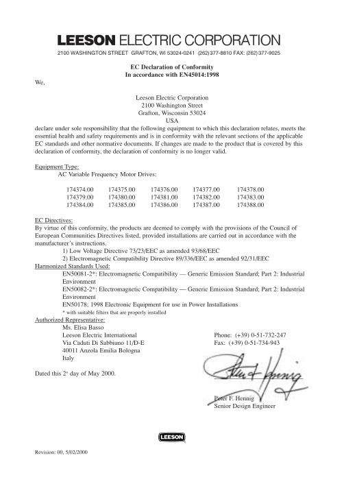
EC Declaration of ConformityIn accordance with EN45014:1998
We,
Leeson Electric Corporation2100 Washington Street
Grafton, Wisconsin 53024USA
declare under sole responsibility that the following equipment to which this declaration relates, meets theessential health and safety requirements and is in conformity with the relevant sections of the applicableEC standards and other normative documents. If changes are made to the product that is covered by thisdeclaration of conformity, the declaration of conformity is no longer valid.
Equipment Type:AC Variable Frequency Motor Drives:
174374.00 174375.00 174376.00 174377.00 174378.00174379.00 174380.00 174381.00 174382.00 174383.00174384.00 174385.00 174386.00 174387.00 174388.00
EC Directives:By virtue of this conformity, the products are deemed to comply with the provisions of the Council ofEuropean Communities Directives listed, provided installations are carried out in accordance with themanufacturer’s instructions.
1) Low Voltage Directive 73/23/EEC as amended 93/68/EEC2) Electromagnetic Compatibility Directive 89/336/EEC as amended 92/31/EEC
Harmonized Standards Used:EN50081-2*: Electromagnetic Compatibility — Generic Emission Standard; Part 2: Industrial EnvironmentEN50082-2*: Electromagnetic Compatibility — Generic Emission Standard; Part 2: Industrial EnvironmentEN50178; 1998 Electronic Equipment for use in Power Installations* with suitable filters that are properly installed
Authorized Representative:Ms. Elisa BassoLeeson Electric International Phone: (+39) 0-51-732-247Via Caduti Di Sabbiuno 11/D-E Fax: (+39) 0-51-734-94340011 Anzola Emilia BolognaItaly
Dated this 2st day of May 2000.
Peter F. HennigSenior Design Engineer
Revision: 00, 5/02/2000
Manual Number: IMSN01
TABLE OF CONTENTS
1.0 GENERAL..................................................................................... 1
2.0 SM-Basic DIMENSIONS................................................... 2
3.0 SM-Basic MODEL DESIGNATION CODE.................... 3
4 . 0 SM-Basic SPECIFICATIONS............................................ 3
5.0 SM-Basic RATINGS............................................................ 4
6.0 INSTALLATION........................................................................... 5
7.0 INPUT AC POWER REQUIREMENTS..................................... 7
8.0 POWER WIRING......................................................................... 8
9.0 SM-Basic POWER WIRING DIAGRAM........................ 9
10.0 CONTROL WIRING.................................................................... 10
1 1 . 0 SM-Basic CONTROL WIRING DIAGRAMS................. 13
12.0 INITIAL POWER UP AND MOTOR ROTATION................... 16
1 3 . 0 PROGRAMMING THE SM Basic DRIVE..................... 18
14.0 PARAMETER MENU.................................................................. 21
15.0 DESCRIPTION OF PARAMETERS.......................................... 23
1 6 . 0 TROUBLESHOOTING..................................................... 37
1 7 . 0 SM-Basic DISPLAY MESSAGES.................................... 39
1 8 . 0 USER SETTING RECORD.............................................. 41
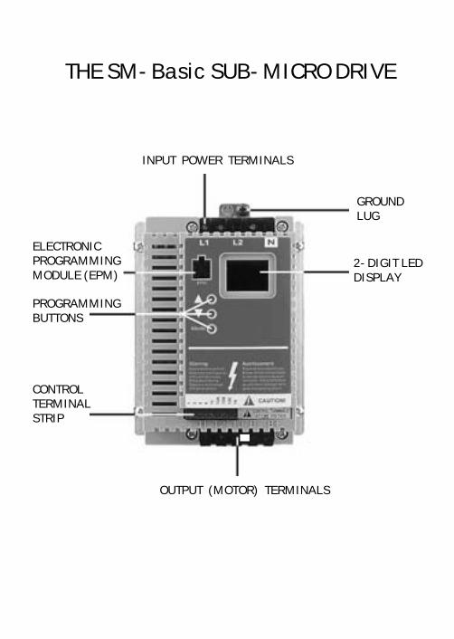
INPUT POWER TERMINALS
OUTPUT (MOTOR) TERMINALS
CONTROLTERMINALSTRIP
2-DIGIT LEDDISPLAY
ELECTRONICPROGRAMMINGMODULE (EPM)
PROGRAMMINGBUTTONS
THE SM-Basic SUB-MICRO DRIVE
GROUNDLUG
1
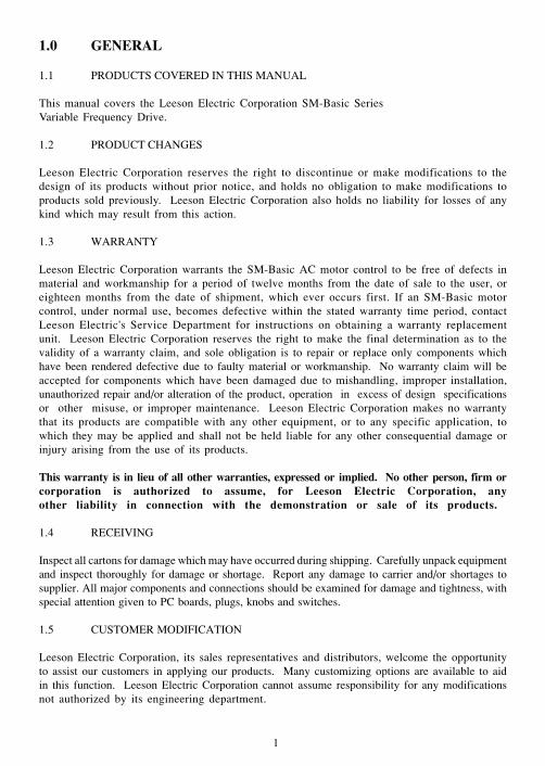
1.0 GENERAL
1.1 PRODUCTS COVERED IN THIS MANUAL
This manual covers the Leeson Electric Corporation SM-Basic SeriesVariable Frequency Drive.
1.2 PRODUCT CHANGES
Leeson Electric Corporation reserves the right to discontinue or make modifications to thedesign of its products without prior notice, and holds no obligation to make modifications toproducts sold previously. Leeson Electric Corporation also holds no liability for losses of anykind which may result from this action.
1.3 WARRANTY
Leeson Electric Corporation warrants the SM-Basic AC motor control to be free of defects inmaterial and workmanship for a period of twelve months from the date of sale to the user, oreighteen months from the date of shipment, which ever occurs first. If an SM-Basic motorcontrol, under normal use, becomes defective within the stated warranty time period, contactLeeson Electric's Service Department for instructions on obtaining a warranty replacementunit. Leeson Electric Corporation reserves the right to make the final determination as to thevalidity of a warranty claim, and sole obligation is to repair or replace only components whichhave been rendered defective due to faulty material or workmanship. No warranty claim will beaccepted for components which have been damaged due to mishandling, improper installation,unauthorized repair and/or alteration of the product, operation in excess of design specificationsor other misuse, or improper maintenance. Leeson Electric Corporation makes no warrantythat its products are compatible with any other equipment, or to any specific application, towhich they may be applied and shall not be held liable for any other consequential damage orinjury arising from the use of its products.
This warranty is in lieu of all other warranties, expressed or implied. No other person, firm orcorporation is authorized to assume, for Leeson Electric Corporation, anyother liability in connection with the demonstration or sale of its products.
1.4 RECEIVING
Inspect all cartons for damage which may have occurred during shipping. Carefully unpack equipmentand inspect thoroughly for damage or shortage. Report any damage to carrier and/or shortages tosupplier. All major components and connections should be examined for damage and tightness, withspecial attention given to PC boards, plugs, knobs and switches.
1.5 CUSTOMER MODIFICATION
Leeson Electric Corporation, its sales representatives and distributors, welcome the opportunityto assist our customers in applying our products. Many customizing options are available to aidin this function. Leeson Electric Corporation cannot assume responsibility for any modificationsnot authorized by its engineering department.
2
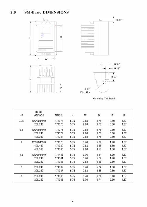
2.0 SM-Basic DIMENSIONS
Mounting Tab Detail
D
H
W
R
P
0.38"
0.38"
0.18"
0.69"
0.19"Dia. Slot
208/240 174387 5.75 2.88 5.56 2.60 4.37
3 208/240 174383 5.75 3.76 6.74 3.40 4.37208/240 174388 5.75 3.76 6.74 2.60 4.37
INPUT
208/240 174386 5.75 2.88 5.56 2.60 4.37
2 208/240 174382 5.75 3.76 5.24 1.90 4.37
480/590 174385 5.75 2.88 4.56 1.60 4.37
1.5 120/208/240 174445 5.75 3.76 5.24 1.90 4.37208/240 174381 5.75 3.76 5.24 1.90 4.37
400/240 174384 5.75 2.88 3.76 0.80 4.37
1 120/208/240 174376 5.75 3.76 5.24 1.90 4.37400/480 174380 5.75 2.88 4.56 1.60 4.37
208/240 174378 5.75 2.88 3.76 0.80 4.37
0.5 120/208/240 174375 5.75 2.88 3.76 0.80 4.37208/240 174379 5.75 2.88 3.76 0.80 4.37
HP VOLTAGE MODEL H W D P R
0.25 120/208/240 174374 5.75 2.88 3.76 0.80 4.37

3
3.0 SM-Basic MODEL DESIGNATION CODE
4.0 SM-Basic SPECIFICATIONS
1 WARNING: Control terminals are not isolated from line voltage! Do not touch!
Storage Temperature -20 to 70 CAmbient Operating Temperature 0 to 50 C (up to 6 kHz carrier, derate above 6 kHz)Ambient Humidity < 95% (non-condensing)Altitude 3300 ft (1000 m) above sea level (without derating)Input Line Voltages 120/208/240 Vac single phase, 208/240 Vac three phaseInput Voltage Tolerance +10%, -15%Input Frequency Tolerance 48 to 62 HzOutput Wave Form Sine Coded PWMOutput Frequency 0 - 99 HzCarrier Frequency 4 kHz to 10 kHzService Factor 1.00 (up to 6 kHz carrier, derate above 6 kHz)Efficiency Up to 98%Power Factor (displacement) 0.96 or betterOverload Current Capacity 150% for 60 seconds, 180% for 30 secondsSpeed Reference Follower Speed Potentiometer, 0-10 VDC (must be isolated)1
Power Supply for Auxiliary Relay 50 mA at 12 VDCDigital Output Circuit rated 50 mA and 30 VDC max (to drive auxiliary relay)1
4
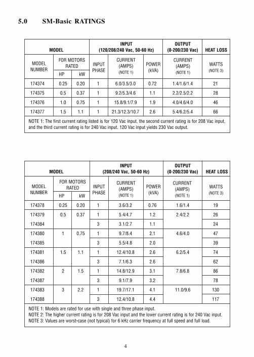
5.0 SM-Basic RATINGS
WATTS(NOTE 3)
WATTS(NOTE 3)
INPUT OUTPUT
MODELNUMBER
FOR MOTORSRATED INPUT
PHASE
CURRENT(AMPS)(NOTE 1)
POWER(kVA)
CURRENT(AMPS)(NOTE 1)
174388 3 12.4/10.8 4.4 117
NOTE 1: Models are rated for use with single and three phase input.NOTE 2: The higher current rating is for 208 Vac input and the lower current rating is for 240 Vac input.NOTE 3: Values are worst-case (not typical) for 6 kHz carrier frequency at full speed and full load.
174383 3 2.2 1 19.7/17.1 4.1 11.0/9.6 130
174387 3 9.1/7.9 3.2 78
MODEL (120/208/240 Vac, 50-60 Hz) (0-200/230 Vac) HEAT LOSS
174382 2 1.5 1 14.8/12.9 3.1 7.8/6.8 86
174386 3 7.1/6.3 2.6 62
HP kW
174381 1.5 1.1 1 12.4/10.8 2.6 6.2/5.4 74
174385 3 5.5/4.8 2.0 39
174380 1 0.75 1 9.7/8.4 2.1 4.6/4.0 47
174384 3 3.1/2.7 1.1 24
174374 0.25 0.20 1 6.0/3.5/3.0 0.72 1.4/1.6/1.4 21
174379 0.5 0.37 1 5.4/4.7 1.2 2.4/2.2 26
174378 0.25 0.20 1 3.6/3.2 0.76 1.6/1.4 19
HP kW
MODEL (208/240 Vac, 50-60 Hz) (0-200/230 Vac) HEAT LOSSINPUT OUTPUT
174375 0.5 0.37 1 9.2/5.3/4.6 1.1 2.2/2.5/2.2 28
MODELNUMBER
FOR MOTORSRATED INPUT
PHASE
CURRENT(AMPS)(NOTE 1)
POWER(kVA)
CURRENT(AMPS)(NOTE 1)
174377 1.5 1.1 1 21.3/12.3/10.7 2.6 5.4/6.2/5.4 66
NOTE 1: The first current rating listed is for 120 Vac input, the second current rating is for 208 Vac input,and the third current rating is for 240 Vac input. 120 Vac input yields 230 Vac output.
174376 1.0 0.75 1 15.8/9.1/7.9 1.9 4.0/4.6/4.0 46
5
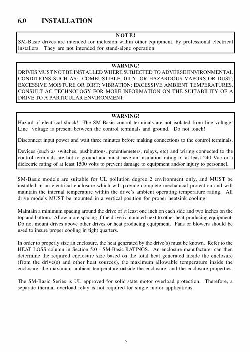
6.0 INSTALLATION
SM-Basic models are suitable for UL pollution degree 2 environment only, and MUST beinstalled in an electrical enclosure which will provide complete mechanical protection and willmaintain the internal temperature within the drive’s ambient operating temperature rating. Alldrive models MUST be mounted in a vertical position for proper heatsink cooling.
Maintain a minimum spacing around the drive of at least one inch on each side and two inches on thetop and bottom. Allow more spacing if the drive is mounted next to other heat-producing equipment.Do not mount drives above other drives or heat producing equipment. Fans or blowers should beused to insure proper cooling in tight quarters.
In order to properly size an enclosure, the heat generated by the drive(s) must be known. Refer to theHEAT LOSS column in Section 5.0 - SM-Basic RATINGS. An enclosure manufacturer can thendetermine the required enclosure size based on the total heat generated inside the enclosure(from the drive(s) and other heat sources), the maximum allowable temperature inside theenclosure, the maximum ambient temperature outside the enclosure, and the enclosure properties.
The SM-Basic Series is UL approved for solid state motor overload protection. Therefore, aseparate thermal overload relay is not required for single motor applications.
WARNING!DRIVES MUST NOT BE INSTALLED WHERE SUBJECTED TO ADVERSE ENVIRONMENTALCONDITIONS SUCH AS: COMBUSTIBLE, OILY, OR HAZARDOUS VAPORS OR DUST;EXCESSIVE MOISTURE OR DIRT; VIBRATION; EXCESSIVE AMBIENT TEMPERATURES.CONSULT AC TECHNOLOGY FOR MORE INFORMATION ON THE SUITABILITY OF ADRIVE TO A PARTICULAR ENVIRONMENT.
N O T E !SM-Basic drives are intended for inclusion within other equipment, by professional electricalinstallers. They are not intended for stand-alone operation.
WARNING!Hazard of electrical shock! The SM-Basic control terminals are not isolated from line voltage!Line voltage is present between the control terminals and ground. Do not touch!
Disconnect input power and wait three minutes before making connections to the control terminals.
Devices (such as switches, pushbuttons, potentiometers, relays, etc) and wiring connected to thecontrol terminals are hot to ground and must have an insulation rating of at least 240 Vac or adielectric rating of at least 1500 volts to prevent damage to equipment and/or injury to personnel.
6
6.1 INSTALLATION AFTER A LONG PERIOD OF STORAGE
If input power has not been applied to the drive for a period of time exceeding three years (due tostorage, etc), the electrolytic DC bus capacitors within the drive can change internally, resulting inexcessive leakage current. This can result in premature failure of the capacitors if the drive is operatedafter such a long period of inactivity or storage.
In order to reform the capacitors and prepare the drive for operation after a long period of inactivity,apply input power to the drive for 8 hours prior to actually operating the motor.
6.2 EXPLOSION PROOF APPLICATIONS
Explosion proof motors that are not rated for inverter use lose their certification when used for variablespeed. Due to the many areas of liability that may be encountered when dealing with these applications,the following statement of policy applies:
“Leeson Electric Corporation inverter products are sold with no warranty offitness for a particular purpose or warranty of suitability for use with explosionproof motors. Leeson Electric Corporation accepts no responsibility for anydirect, incidental or consequential loss, cost, or damage that may arise throughthe use of its AC inverter products in these applications. The purchaser expresslyagrees to assume all risk of any loss, cost, or damage that may arise from suchapplication. Leeson Electric Corporation or Leeson Electric Corporation’sengineering department will not knowingly approve applications involvingexplosion proof motors.”
WARNING!Severe damage to the drive can result if it is operated after a long period of storage or inactivitywithout reforming the DC bus capacitors!

7
WARNING!Hazard of electrical shock! Capacitors retain charge after power is removed. Disconnect incomingpower and wait until the voltage between terminals B+ and B- is 0 VDC before servicing the drive.
7.0 INPUT AC POWER REQUIREMENTS
The input voltage must match the nameplate voltage rating of the drive. Voltage fluctuation must notvary by greater than 10% overvoltage or 15% undervoltage.
NOTE: Drives with dual input voltage ratings must be programmed for the proper supply voltage(refer to Parameter 01 - LINE VOLTAGE SELECTION in Section 15.0 - DESCRIPTION OFPARAMETERS).
The drive is suitable for use on a circuit capable of delivering not more than 5,000 RMS symmetricalamperes at the drive’s rated voltage.
Three phase voltage imbalance must be less than 2.0% phase to phase. Excessive phase to phaseimbalance can cause severe damage to the drive.
Motor voltage should match line voltage in normal applications. The drive’s maximum output voltagewill equal the input voltage. Use extreme caution when using a motor with a voltage rating which isdifferent from the input line voltage.
7.1 INPUT VOLTAGE RATINGS
SM-Basic Series drives are rated for 120/208/240 Vac, single phase, 50-60 Hz input. Thedrive will function with input voltage of 120 Vac (+10%, -15%), at 48 to 60 Hz, or with inputvoltage of 208 to 240 Vac (+ 10%, - 15%), at 48 to 62 Hz.
SM-Basic Series drives are rated for 208/240 Vac, single phase, 50-60 Hz input. The drivewill function with input voltages of 208 to 240 Vac (+10%, -15%), at 48 to 62 Hz.
SM-Basic Series drives are rated for 208/240 Vac, three phase, 50-60 Hz input. The drive willfunction with input voltages of 208 to 240 Vac (+ 10%, - 15%), at 48 to 62 Hz.
NOTE: Parameter 01 - LINE VOLTAGE SELECTION must be programmed according to the appliedinput voltage. See Section 15.0 - DESCRIPTION OF PARAMETERS.
7.2 INPUT FUSING AND DISCONNECT REQUIREMENTS
A circuit breaker or a disconnect switch with fuses must be provided in accordance with the NationalElectric Code (NEC) and all local codes.
The SM-Basic drive is capable of withstanding up to 150% current overload for 60 seconds.Select a fuse or magnetic trip circuit breaker rated at 1.5 times the input current rating of thedrive (the minimum fuse size should be 10 amps, regardless of input current rating). Refer toSection 5.0 - SM-Basic RATINGS.
8
Minimum voltage rating of the protection device should be 250 Vac for 120/208/240 Vac and 208/240 Vac rated drives.
UL Class CC fast-acting, current limiting type fuses should be used when input fusing is required.Select fuses with low I 2 T values, rated at 200,000 AIC. Recommended fuses are Bussman KTK-R.Similar fuses with equivalent ratings by other manufacturers may also be acceptable.
8.0 POWER WIRING
Note drive input and output current ratings and check applicable electrical codes for required wiretype and size, grounding requirements, over-current protection, and incoming power disconnect,before wiring the drive. Size conservatively to minimize voltage drop.
Strip off 0.20 to 0.25 inches of insulation for input power, output power, and DC Bus wiring. Theinput power, output power, and DC Bus terminals must be tightened to a torque of 4.0 to 4.5 lb-in.
Input fusing and a power disconnect switch or contactor MUST be wired in series with terminals L1,L2, and L3 for three phase input models. For 208/240 Vac single phase input models, use terminalsL1 and L2. For 120 Vac single phase input models, use terminals L1 and N. This disconnect must beused to power down the drive when servicing, or when the drive is not to be operated for a longperiod of time, but should not be used to start and stop the motor. Repetitive cycling of a disconnector input contactor (more than once every two minutes) may cause damage to the drive.
8.1 WIRING FOR SINGLE PHASE OR THREE PHASE INPUT
If the drive is rated for 120/208/240 Vac single phase input, wire the input to terminals L1 andN for 120 Vac voltage, or wire to terminals L1 and L2 (do not wire to N) for 208/240 Vac inputvoltage. Refer to Section 9.0 - SM-Basic POWER WIRING DIAGRAM.
If the drive is rated for 208/240 Vac single phase input, wire the input to terminals L1 and L2.
If the drive is rated for three phase input, wire the input to terminals L1, L2, and L3.
All three power output wires, from terminals T1, T2, and T3 to the motor, must be kept tightlybundled and run in a separate conduit away from all other power and control wiring.
Do not install contactors or disconnects between the drive and motor without consulting LeesonElectric Corporation for more information.
WARNING!Hazard of electrical shock! Capacitors retain charge after power is removed. Disconnect incomingpower and wait until the voltage between terminals B+ and B- is 0 VDC before servicing the drive.
9
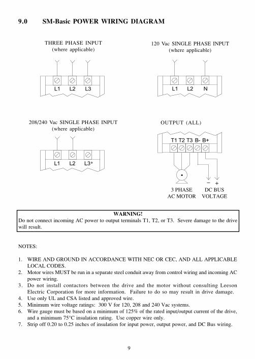
THREE PHASE INPUT(where applicable)
3 PHASEAC MOTOR
120 Vac SINGLE PHASE INPUT(where applicable)
208/240 Vac SINGLE PHASE INPUT(where applicable)
DC BUSVOLTAGE
OUTPUT (ALL)
+
NOTES:
1. WIRE AND GROUND IN ACCORDANCE WITH NEC OR CEC, AND ALL APPLICABLELOCAL CODES.
2. Motor wires MUST be run in a separate steel conduit away from control wiring and incoming ACpower wiring.
3. Do not install contactors between the drive and the motor without consulting LeesonElectric Corporation for more information. Failure to do so may result in drive damage.
4. Use only UL and CSA listed and approved wire.5. Minimum wire voltage ratings: 300 V for 120, 208 and 240 Vac systems.6. Wire gauge must be based on a minimum of 125% of the rated input/output current of the drive,
and a minimum 75°C insulation rating. Use copper wire only.7. Strip off 0.20 to 0.25 inches of insulation for input power, output power, and DC Bus wiring.
9.0 SM-Basic POWER WIRING DIAGRAM
WARNING!Do not connect incoming AC power to output terminals T1, T2, or T3. Severe damage to the drivewill result.
*

10
10.0 CONTROL WIRING
10.1 CONTROL WIRING VS. POWER WIRING
External control wiring MUST be run in a separate conduit away from all other input and outputpower wiring. If control wiring is not kept separate from power wiring, electrical noise may begenerated on the control wiring that will cause erratic drive behavior. Use twisted wires or shieldedcable rated for 300 VDC minimum (do not ground the shield).
10.2 SURGE SUPPRESION ON RELAYS
Current and voltage surges and spikes in the coils of contactors, relays, and solenoids, near or connectedto the drive, can cause erratic drive operation. Snubbers should be used on any coils associated withthe drive. For AC loads, snubbers should consist of a resistor and a capacitor in series across the coil.For DC loads, a free-wheeling or flyback diode should be placed across the coil.
10.3 START/STOP CONTROL
There are various control schemes that allow for 2-wire and 3-wire Start/Stop circuits. Refer to thewiring diagrams in Section 11.0 - SM-Basic CONTROL WIRING DIAGRAMS.
10.4 SPEED REFERENCE SIGNALS
SPEED POT Connect the wiper to terminal TB-5, and connect the high and low end leads toterminals TB-6 and TB-3, respectively. The speed pot can be 5kΩ up to 10kΩ.
0-10 VDC Wire the positive to terminal TB-5 and the negative to terminal TB-3. The 0-10VDC signal must be isolated, as the control terminals are at line voltage potential.
DO NOT connect the low side of the speed pot or 0-10 VDC signal to ground.
WARNING!Hazard of electrical shock! The SM-Basic control terminals are not isolated from line voltage!Line voltage is present between the control terminals and ground. Do not touch!
Disconnect input power and wait three minutes before making connections to the control terminals.
Devices (such as switches, pushbuttons, potentiometers, relays, etc) and wiring connected to thecontrol terminals are hot to ground and must have an insulation rating of at least 240 Vac or adielectric rating of at least 1500 volts to prevent damage to equipment and/or injury to personnel.
11
10.5 SPEED REFERENCE SELECTION
If a speed pot is to be used to control the drive speed, terminal TB-13A, 13B, or 13C (Parameter 10,11, or 12) may be programmed as the input select for the speed pot. When that TB-13 terminal is thenclosed to TB-11, the drive will follow the speed pot input.
If the speed pot is not selected on the terminal strip using TB-13A, 13B, or 13C, speed control willdefault to STANDARD mode, which is governed by the setting of Parameter 05 - STANDARDSPEED SOURCE. The STANDARD SPEED SOURCE can be the and buttons on the front ofthe drive, PRESET SPEED #1 (Parameter 31), or a speed pot.
PRESET SPEEDS
TB-13A can be programmed to select PRESET SPEED #1, TB-13B to select PRESET SPEED #2,and TB-13C to select PRESET SPEED #3. There are a total of seven preset speeds, which areactivated by different combinations of contact closures between TB-13A, 13B, 13C and TB-11. Referto Parameters 31-37 in Section 15.0 - DESCRIPTION OF PARAMETERS.
JOG
TB-13B can be programmed to select either JOG FORWARD or JOG REVERSE. The Jog speed isset by PRESET SPEED #2. Close TB-13B to TB-11 to JOG, and open the contact to STOP.
NOTE: If the drive is commanded to JOG while running, the drive will enter JOG mode and run atPRESET SPEED #2. When the JOG command is removed, the drive will STOP.
MOTOR OPERATED POT (MOP) / FLOATING POINT CONTROL
TB-13B and TB-13C are required for this function, which controls the drive speed using normallyopen contacts wired to the terminal strip. Program TB-13B for DECREASE FREQ, and programTB-13C for INCREASE FREQ. Closing the contacts between the TB-13 terminals and TB-11 willcause the speed setpoint to increase or decrease until the contact is opened. The INCREASE FREQfunction will only operate while the drive is running.
NOTE: If TB-13A, TB-13B, and TB-13C are all programmed to select speed references, and two orthree of the terminals are closed to TB-11, the higher terminal has priority and will override theothers. For example, if TB-13A is programmed to select a speed pot, and TB-13C is programmed toselect PRESET SPEED #3, closing both terminals to TB-11 will cause the drive to respond to PRESETSPEED #3, because TB-13C overrides TB-13A.
WARNING!When operating in JOG mode, the STOP signal and the AUXILIARY STOP function (see Parameters10-12) WILL NOT stop the drive. To stop the drive, remove the JOG command.
JOG REVERSE will operate the drive in reverse rotation even if ROTATION DIRECTION (Parameter17) is set to FORWARD ONLY.
12
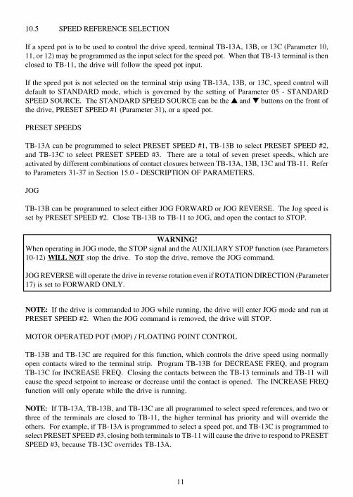
10.7 DRIVE STATUS DIGITAL OUTPUTS
There is one open-collector output at terminal TB-14. The open-collector circuit is a current-sinkingtype rated at 30 VDC and 50 mA maximum.
The open-collector output can be programmed to indicate any one of the following: RUN, FAULT,INVERSE FAULT, FAULT LOCKOUT, AT SPEED, ABOVE PRESET SPEED #3, CURRENTLIMIT, AUTO SPEED MODE, and REVERSE. Refer to Parameter 06 in Section 15.0 -DESCRIPTION OF PARAMETERS.
TB-11
TB-14SCN
TE
RM
INA
L S
TR
IP
RELAY COIL
DIODE SNUBBER(RECOMMENDED)
WARNING!Hazard of electrical shock! The SCN control terminals are not isolated from line voltage! Linevoltage is present between the control terminals and ground. Do not touch!
Only use relays with an insulation rating of at least 240 Vac or a dielectric rating of at least 1500 voltsto prevent damage to equipment and/or injury to personnel.
NOTE: When the optional remote keypad is used, TB-14 is wired to the remote keypad and cannotbe used for status indication.
13
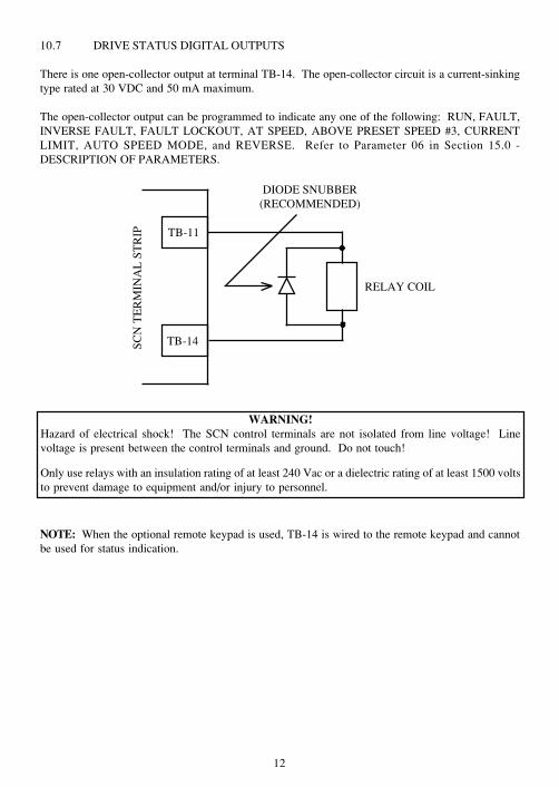
11.0 SM-Basic CONTROL WIRING DIAGRAMS
11.1 TWO-WIRE START/STOP CONTROL
NOTES:
1. Close TB-1 to TB-11 to RUN, and open to STOP. TB-1 functions as a RUN input for two-wirestart/stop circuits, and a STOP input for three-wire start/stop circuits. Refer to Section 11.2.
2. If reverse direction is required, set ROTATION (Parameter 17) to FORWARD AND REVERSE(02), and program TB-13A (Parameter 10) to RUN REVERSE (05). Close TB-13A to TB-11 toRUN in the reverse direction, and open to STOP.
3. For speed pot control, set STANDARD SPEED SOURCE (Parameter 05) to SPEED POT (03).
RU
N
SPE
ED
PO
T C
OM
MO
N
SPE
ED
PO
T I
NPU
T
SPE
ED
PO
T P
OW
ER
SU
PPL
Y
TB
-13A
FU
NC
TIO
N S
EL
EC
T(R
UN
RE
VE
RSE
)
TB
-13B
FU
NC
TIO
N S
EL
EC
T
TB
-13C
FU
NC
TIO
N S
EL
EC
T
OP
EN
-CO
LL
EC
TO
R O
UT
PU
T
DIG
ITA
L I
NPU
T R
EFE
RE
NC
E
MAINTAINEDRUN/STOP CONTACT
(FORWARD)
SPEEDPOT
MAINTAINEDRUN/STOP CONTACT
(REVERSE)
WARNING!Hazard of electrical shock! The SM-Basic control terminals are not isolated from line voltage!Line voltage is present between the control terminals and ground. Do not touch!
Disconnect input power and wait three minutes before making connections to the control terminals.
Devices (such as switches, pushbuttons, potentiometers, relays, etc) and wiring connected to thecontrol terminals are hot to ground and must have an insulation rating of at least 240 Vac or adielectric rating of at least 1500 volts to prevent damage to equipment and/or injury to personnel.
14
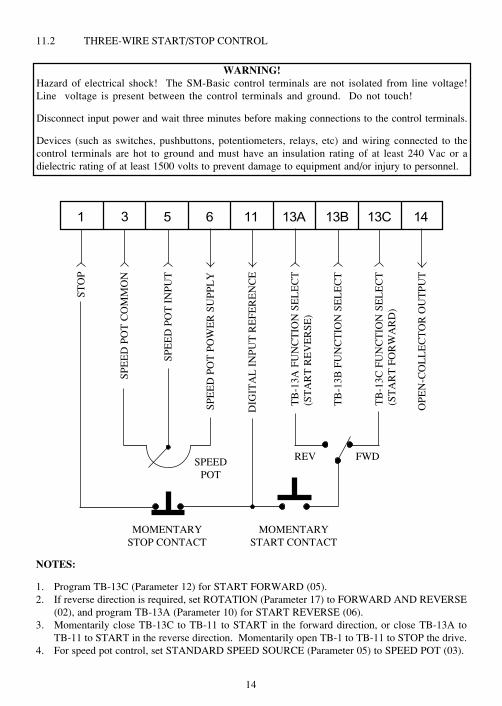
11.2 THREE-WIRE START/STOP CONTROL
NOTES:
1. Program TB-13C (Parameter 12) for START FORWARD (05).2. If reverse direction is required, set ROTATION (Parameter 17) to FORWARD AND REVERSE
(02), and program TB-13A (Parameter 10) for START REVERSE (06).3. Momentarily close TB-13C to TB-11 to START in the forward direction, or close TB-13A to
TB-11 to START in the reverse direction. Momentarily open TB-1 to TB-11 to STOP the drive.4. For speed pot control, set STANDARD SPEED SOURCE (Parameter 05) to SPEED POT (03).
STO
P
SPE
ED
PO
T C
OM
MO
N
SPE
ED
PO
T I
NPU
T
SPE
ED
PO
T P
OW
ER
SU
PPL
Y
TB
-13A
FU
NC
TIO
N S
EL
EC
T(S
TA
RT
RE
VE
RSE
)
TB
-13B
FU
NC
TIO
N S
EL
EC
T
TB
-13C
FU
NC
TIO
N S
EL
EC
T(S
TA
RT
FO
RW
AR
D)
OPE
N-C
OL
LE
CT
OR
OU
TP
UT
DIG
ITA
L I
NPU
T R
EFE
RE
NC
E
MOMENTARYSTOP CONTACT
SPEEDPOT
MOMENTARYSTART CONTACT
REV FWD
WARNING!Hazard of electrical shock! The SM-Basic control terminals are not isolated from line voltage!Line voltage is present between the control terminals and ground. Do not touch!
Disconnect input power and wait three minutes before making connections to the control terminals.
Devices (such as switches, pushbuttons, potentiometers, relays, etc) and wiring connected to thecontrol terminals are hot to ground and must have an insulation rating of at least 240 Vac or adielectric rating of at least 1500 volts to prevent damage to equipment and/or injury to personnel.
15
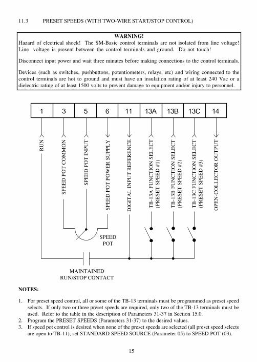
11.3 PRESET SPEEDS (WITH TWO-WIRE START/STOP CONTROL)
NOTES:
1. For preset speed control, all or some of the TB-13 terminals must be programmed as preset speedselects. If only two or three preset speeds are required, only two of the TB-13 terminals must beused. Refer to the table in the description of Parameters 31-37 in Section 15.0.
2. Program the PRESET SPEEDS (Parameters 31-37) to the desired values.3. If speed pot control is desired when none of the preset speeds are selected (all preset speed selects
are open to TB-11), set STANDARD SPEED SOURCE (Parameter 05) to SPEED POT (03).
RU
N
SPE
ED
PO
T C
OM
MO
N
SPE
ED
PO
T I
NPU
T
SPE
ED
PO
T P
OW
ER
SU
PPL
Y
TB
-13A
FU
NC
TIO
N S
EL
EC
T(P
RE
SET
SPE
ED
#1)
TB
-13B
FU
NC
TIO
N S
EL
EC
T(P
RE
SET
SPE
ED
#2)
TB
-13C
FU
NC
TIO
N S
EL
EC
T(P
RE
SET
SPE
ED
#3)
OP
EN
-CO
LL
EC
TO
R O
UT
PU
T
DIG
ITA
L I
NPU
T R
EFE
RE
NC
E
MAINTAINEDRUN/STOP CONTACT
SPEEDPOT
WARNING!Hazard of electrical shock! The SM-Basic control terminals are not isolated from line voltage!Line voltage is present between the control terminals and ground. Do not touch!
Disconnect input power and wait three minutes before making connections to the control terminals.
Devices (such as switches, pushbuttons, potentiometers, relays, etc) and wiring connected to thecontrol terminals are hot to ground and must have an insulation rating of at least 240 Vac or adielectric rating of at least 1500 volts to prevent damage to equipment and/or injury to personnel.
16
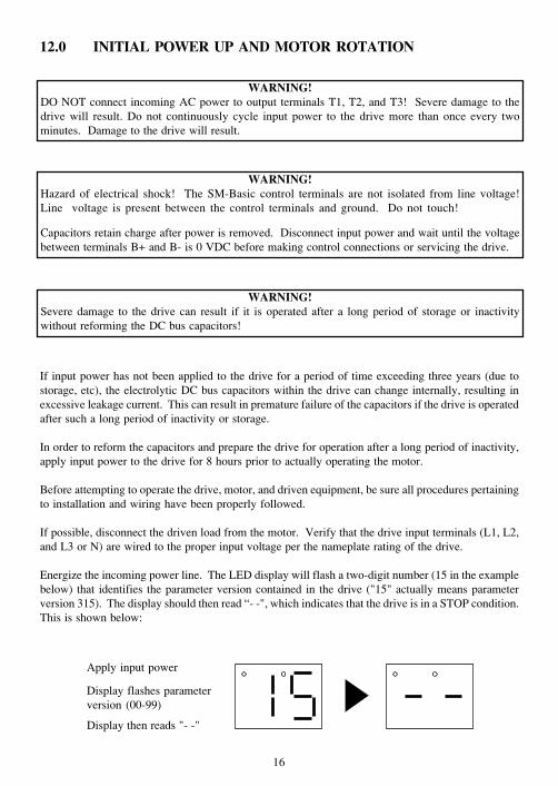
12.0 INITIAL POWER UP AND MOTOR ROTATION
If input power has not been applied to the drive for a period of time exceeding three years (due tostorage, etc), the electrolytic DC bus capacitors within the drive can change internally, resulting inexcessive leakage current. This can result in premature failure of the capacitors if the drive is operatedafter such a long period of inactivity or storage.
In order to reform the capacitors and prepare the drive for operation after a long period of inactivity,apply input power to the drive for 8 hours prior to actually operating the motor.
Before attempting to operate the drive, motor, and driven equipment, be sure all procedures pertainingto installation and wiring have been properly followed.
If possible, disconnect the driven load from the motor. Verify that the drive input terminals (L1, L2,and L3 or N) are wired to the proper input voltage per the nameplate rating of the drive.
Energize the incoming power line. The LED display will flash a two-digit number (15 in the examplebelow) that identifies the parameter version contained in the drive ("15" actually means parameterversion 315). The display should then read “- -", which indicates that the drive is in a STOP condition.This is shown below:
WARNING!DO NOT connect incoming AC power to output terminals T1, T2, and T3! Severe damage to thedrive will result. Do not continuously cycle input power to the drive more than once every twominutes. Damage to the drive will result.
WARNING!Severe damage to the drive can result if it is operated after a long period of storage or inactivitywithout reforming the DC bus capacitors!
WARNING!Hazard of electrical shock! The SM-Basic control terminals are not isolated from line voltage!Line voltage is present between the control terminals and ground. Do not touch!
Capacitors retain charge after power is removed. Disconnect input power and wait until the voltagebetween terminals B+ and B- is 0 VDC before making control connections or servicing the drive.
Apply input power
Display then reads "- -"
Display flashes parameterversion (00-99)
17
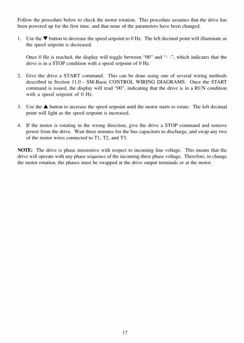
Follow the procedure below to check the motor rotation. This procedure assumes that the drive hasbeen powered up for the first time, and that none of the parameters have been changed.
1. Use the button to decrease the speed setpoint to 0 Hz. The left decimal point will illuminate asthe speed setpoint is decreased.
Once 0 Hz is reached, the display will toggle between “00” and “- -”, which indicates that thedrive is in a STOP condition with a speed setpoint of 0 Hz.
2. Give the drive a START command. This can be done using one of several wiring methodsdescribed in Section 11.0 - SM-Basic CONTROL WIRING DIAGRAMS. Once the STARTcommand is issued, the display will read “00”, indicating that the drive is in a RUN conditionwith a speed setpoint of 0 Hz.
3. Use the button to increase the speed setpoint until the motor starts to rotate. The left decimalpoint will light as the speed setpoint is increased.
4. If the motor is rotating in the wrong direction, give the drive a STOP command and removepower from the drive. Wait three minutes for the bus capacitors to discharge, and swap any twoof the motor wires connected to T1, T2, and T3.
NOTE: The drive is phase insensitive with respect to incoming line voltage. This means that thedrive will operate with any phase sequence of the incoming three phase voltage. Therefore, to changethe motor rotation, the phases must be swapped at the drive output terminals or at the motor.
18
Press to enter password
Use and to scroll to thepassword value
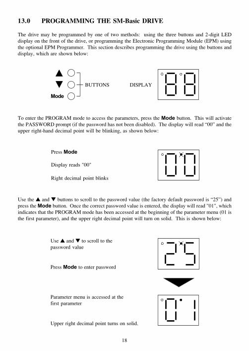
13.0 PROGRAMMING THE SM-Basic DRIVE
The drive may be programmed by one of two methods: using the three buttons and 2-digit LEDdisplay on the front of the drive, or programming the Electronic Programming Module (EPM) usingthe optional EPM Programmer. This section describes programming the drive using the buttons anddisplay, which are shown below:
To enter the PROGRAM mode to access the parameters, press the button. This will activatethe PASSWORD prompt (if the password has not been disabled). The display will read “00” and theupper right-hand decimal point will be blinking, as shown below:
Use the and buttons to scroll to the password value (the factory default password is “25”) andpress the button. Once the correct password value is entered, the display will read "01", whichindicates that the PROGRAM mode has been accessed at the beginning of the parameter menu (01 isthe first parameter), and the upper right decimal point will turn on solid. This is shown below:
Parameter menu is accessed at thefirst parameter
BUTTONS
Press
Right decimal point blinks
Display reads "00"
DISPLAY
Upper right decimal point turns on solid.
19
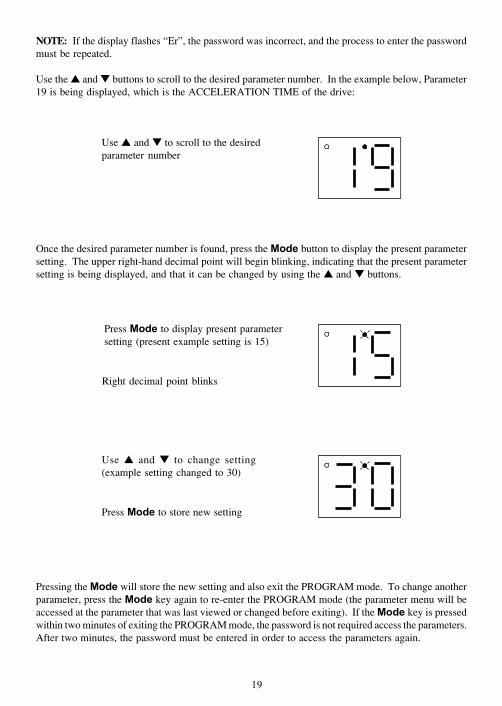
NOTE: If the display flashes “Er”, the password was incorrect, and the process to enter the passwordmust be repeated.
Use the and buttons to scroll to the desired parameter number. In the example below, Parameter19 is being displayed, which is the ACCELERATION TIME of the drive:
Once the desired parameter number is found, press the button to display the present parametersetting. The upper right-hand decimal point will begin blinking, indicating that the present parametersetting is being displayed, and that it can be changed by using the and buttons.
Use and to change setting(example setting changed to 30)
Press to store new setting
Pressing the will store the new setting and also exit the PROGRAM mode. To change anotherparameter, press the key again to re-enter the PROGRAM mode (the parameter menu will beaccessed at the parameter that was last viewed or changed before exiting). If the key is pressedwithin two minutes of exiting the PROGRAM mode, the password is not required access the parameters.After two minutes, the password must be entered in order to access the parameters again.
Use and to scroll to the desiredparameter number
Press to display present parametersetting (present example setting is 15)
Right decimal point blinks
20
13.2 ELECTRONIC PROGRAMMING MODULE (EPM)
Every SM-Basic Series drive has an Electronic Programming Module (EPM) installed on themain control board. The EPM stores the user’s parameter settings and special OEM defaultsettings (if programmed). The EPM is removable, allowing it to be installed in another drive forquick set-up. For example, if a drive is being replaced with a new one, the EPM can be taken outof the first drive and installed in the new drive. Downtime is minimized because the new drivedoes not require programming - it is ready to run when the EPM is installed.
The SM-Basic Series drive contains two or three sets of parameter values, depending on whetherthe drive has been programmed with optional OEM default settings. The first set of values is thefactory default settings, which are permanently stored on the main control board and cannot bechanged. The second set of values is the user settings, which are stored in the EPM. When thedrive leaves the factory, the user settings are the same as the factory default settings, but the usersettings can be changed to configure the drive for a particular application. The optional third setof values is the OEM default settings, which are also stored in the EPM. OEM default settingsare typically used in cases where many drives are used for the same application, which requiresthat all of the drives have the same parameter settings. The OEM default settings cannot bechanged without the optional EPM Programmer. The drive can be programmed to operateaccording to the user settings or the OEM default settings (see Parameter 48 in Section 15.0).
NOTE: The drive will not operate without the EPM installed. The drive will display “F1” if theEPM is missing or damaged.
An EPM Programmer is available as an option from SM-Basic, which has the ability to quicklyand easily program many SM-Basic drives for the same configuration. Once a “master” EPM isprogrammed with the desired parameter settings, the EPM Programmer can copy those settingsto other EPMs, allowing many drives to be configured very quickly. Please consult the EPMProgrammer Instruction Manual or contact the factory for more information.
If the OEM settings in the EPM become corrupted, the drive will operate normally, until an attemptis made to perform a RESET OEM using Parameter 48 - PROGRAM SELECTION. The drive willthen flash “GF” to indicate that the OEM settings are no longer valid. This will require that the EPMbe re-programmed using the optional EPM Programmer.
If the OEM settings and the user settings are both corrupted, the drive will display “GF” immediatelyand the drive will require a RESET 60 or RESET 50 using Parameter 48 - PROGRAM SELECTION.Once the RESET is performed, the parameters can then be programmed individually to match theOEM default settings. This will allow the drive to operate as if it were in OEM mode, even though itis actually operating in USER mode. Refer to Parameter 48 in Section 15.0 - DESCRIPTION OFPARAMETERS.
NOTE: The drive will also display “GF” if a RESET OEM or OPERATE WITH OEM SETTINGSis attempted when the drive is not equipped with the OEM default option.
WARNING!Do not remove the EPM while power is applied to the drive. Damage to the EPM and/or drive mayresult.
21
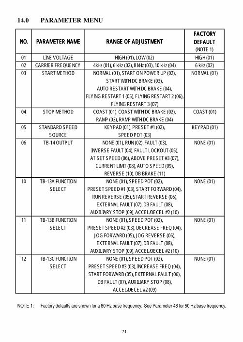
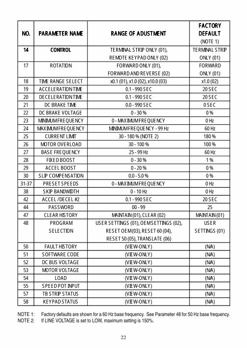
14.0 PARAMETER MENU
NOTE 1: Factory defaults are shown for a 60 Hz base frequency. See Parameter 48 for 50 Hz base frequency.
FACTORYFACTORYFACTORYFACTORYNO.NO.NO.NO. PARAMETER NAMEPARAMETER NAMEPARAMETER NAMEPARAMETER NAME RANGE OF ADJUSTMENTRANGE OF ADJUSTMENTRANGE OF ADJUSTMENTRANGE OF ADJUSTMENT DEFAULTDEFAULTDEFAULTDEFAULT
(NOTE 1)01 LINE VOLTAGE HIGH (01), LOW (02) HIGH (01)02 CARRIER FREQUENCY 4kHz (01), 6 kHz (02), 8 kHz (03), 10 kHz (04) 6 kHz (02)03 START METHOD NORMAL (01), START ON POWER UP (02), NORMAL (01)
START WITH DC BRAKE (03),AUTO RESTART WITH DC BRAKE (04),
FLYING RESTART 1 (05), FLYING RESTART 2 (06),FLYING RESTART 3 (07)
04 STOP METHOD COAST (01), COAST WITH DC BRAKE (02), COAST (01)RAMP (03), RAMP WITH DC BRAKE (04)
05 STANDARD SPEED KEYPAD (01), PRESET #1 (02), KEYPAD (01)SOURCE SPEED POT (03)
06 TB-14 OUTPUT NONE (01), RUN (02), FAULT (03), NONE (01)INVERSE FAULT (04), FAULT LOCKOUT (05),AT SET SPEED (06), ABOVE PRESET #3 (07),
CURRENT LIMIT (08), AUTO SPEED (09),REVERSE (10), DB BRAKE (11)
10 TB-13A FUNCTION NONE (01), SPEED POT (02), NONE (01)SELECT PRESET SPEED #1 (03), START FORWARD (04),
RUN REVERSE (05), START REVERSE (06),EXTERNAL FAULT (07), DB FAULT (08),
AUXILIARY STOP (09), ACCEL/DECEL #2 (10)11 TB-13B FUNCTION NONE (01), SPEED POT (02), NONE (01)
SELECT PRESET SPEED #2 (03), DECREASE FREQ (04),JOG FORWARD (05), JOG REVERSE (06),EXTERNAL FAULT (07), DB FAULT (08),
AUXILIARY STOP (09), ACCEL/DECEL #2 (10)12 TB-13C FUNCTION NONE (01), SPEED POT (02), NONE (01)
SELECT PRESET SPEED #3 (03), INCREASE FREQ (04),START FORWARD (05), EXTERNAL FAULT (06),
DB FAULT (07), AUXILIARY STOP (08),ACCEL/DECEL #2 (09)
22
NOTE 1: Factory defaults are shown for a 60 Hz base frequency. See Parameter 48 for 50 Hz base frequency.NOTE 2: If LINE VOLTAGE is set to LOW, maximum setting is 150%.
FACTORYFACTORYFACTORYFACTORYNO.NO.NO.NO. PARAMETER NAMEPARAMETER NAMEPARAMETER NAMEPARAMETER NAME RANGE OF ADUSTMENTRANGE OF ADUSTMENTRANGE OF ADUSTMENTRANGE OF ADUSTMENT DEFAULTDEFAULTDEFAULTDEFAULT
(NOTE 1)14141414 CONTROLCONTROLCONTROLCONTROL TERMINAL STRIP ONLY (01), TERMINAL STRIP
REMOTE KEYPAD ONLY (02) ONLY (01)17 ROTATION FORWARD ONLY (01), FORWARD
FORWARD AND REVERSE (02) ONLY (01)18 TIME RANGE SELECT x0.1 (01), x1.0 (02), x10.0 (03) x1.0 (02)19 ACCELERATION TIME 0.1 - 990 SEC 20 SEC20 DECELERATION TIME 0.1 - 990 SEC 20 SEC21 DC BRAKE TIME 0.0 - 990 SEC 0 SEC22 DC BRAKE VOLTAGE 0 - 30 % 0 %23 MINIMUM FREQUENCY 0 - MAXIMUM FREQUENCY 0 Hz24 MAXIMUM FREQUENCY MINIMUM FREQUENCY - 99 Hz 60 Hz25 CURRENT LIMIT 30 - 180 % (NOTE 2) 180 %26 MOTOR OVERLOAD 30 - 100 % 100 %27 BASE FREQUENCY 25 - 99 Hz 60 Hz28 FIXED BOOST 0 - 30 % 1 %29 ACCEL BOOST 0 - 20 % 0 %30 SLIP COMPENSATION 0.0 - 5.0 % 0 %
31-37 PRESET SPEEDS 0 - MAXIMUM FREQUENCY 0 Hz38 SKIP BANDWIDTH 0 - 10 Hz 0 Hz42 ACCEL / DECEL #2 0.1 - 990 SEC 20 SEC44 PASSWORD 00 - 99 2547 CLEAR HISTORY MAINTAIN (01), CLEAR (02) MAINTAIN (01)48 PROGRAM USER SETTINGS (01), OEM SETTINGS (02), USER
SELECTION RESET OEM (03), RESET 60 (04), SETTINGS (01)RESET 50 (05), TRANSLATE (06)
50 FAULT HISTORY (VIEW-ONLY) (N/A)51 SOFTWARE CODE (VIEW-ONLY) (N/A)52 DC BUS VOLTAGE (VIEW-ONLY) (N/A)53 MOTOR VOLTAGE (VIEW-ONLY) (N/A)54 LOAD (VIEW-ONLY) (N/A)55 SPEED POT INPUT (VIEW-ONLY) (N/A)57 TB STRIP STATUS (VIEW-ONLY) (N/A)58 KEYPAD STATUS (VIEW-ONLY) (N/A)
23
NOTE: If this parameter is changed while the drive is running, the new value will not take effectuntil the drive is stopped.
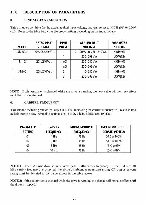
02 CARRIER FREQUENCY
This sets the switching rate of the output IGBT’s. Increasing the carrier frequency will result in lessaudible motor noise. Available settings are: 4 kHz, 6 kHz, 8 kHz, and 10 kHz.
15.0 DESCRIPTION OF PARAMETERS
01 LINE VOLTAGE SELECTION
This calibrates the drive for the actual applied input voltage, and can be set to HIGH (01) or LOW(02). Refer to the table below for the proper setting depending on the input voltage.
NOTE 1: The SM-Basic drive is fully rated up to 6 kHz carrier frequency. If the 8 kHz or 10kHz carrier frequency is selected, the drive’s ambient temperature rating OR output currentrating must be de-rated to the value shown in the table above.
NOTE 2: If this parameter is changed while the drive is running, the change will not take effect untilthe drive is stopped.
RATED INPUTRATED INPUTRATED INP RPARAMETERPARAMETERMODELMODELMODELMODEL VOLTAGEVOLTAGEVOLTAGEVOLTAGE PHASEPHASEPHASEPHASE VOLTAGEVOLTAGEVOLTAGEVOLTAGE SETTINGSETTINGSETTINGSETTINGSN100S 120 / 208 / 240 Vac 1 110 - 120 Vac or 220 - 240 Vac HIGH (01)
1 200 - 208 Vac LOW (02)208 / 240 Vac 1 or 3 220 - 240 Vac HIGH (01)
1 or 3 200 - 208 Vac LOW (02)SN200 208 / 240 Vac 3 240 Vac HIGH (01)
3 200 - 208 Vac LOW (02)
N
PLIED INPUTAPPLIED INPUTAPPLIED INPUTAPPLIED INPUT PARAMETERPARAMETE
0S
UTRATED INPUT INPUTINPUTINPUTINPUT AP
0 -
PARAMETERPARAMETERPARAMETERPARAMETER CARRIERCARRIERCARRIERCARRIER MAXIMUM OUTPUTMAXIMUM OUTPUTMAXIMUM OUTPUTMAXIMUM OUTPUT AMBIENT OR OUTPUTAMBIENT OR OUTPUTAMBIENT OR OUTPUTAMBIENT OR OUTPUTSETTINGSETTINGSETTINGSETTING FREQUENCYFREQUENCYFREQUENCYFREQUENCY FREQUENCYFREQUENCYFREQUENCYFREQUENCY DERATE (NOTE 2)DERATE (NOTE 2)DERATE (NOTE 2)DERATE (NOTE 2)
01 4 kHz 99 Hz 50 C or 100%02 6 kHz 99 Hz 50 C or 100%03 8 kHz 99 Hz 43 C or 92%04 10 kHz 99 Hz 35 C or 82%
24
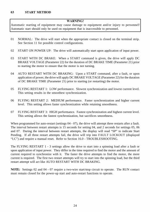
03 START METHOD
01 NORMAL: The drive will start when the appropriate contact is closed on the terminal strip.See Section 11 for possible control configurations.
02 START ON POWER UP: The drive will automatically start upon application of input power.
03 START WITH DC BRAKE: When a START command is given, the drive will apply DCBRAKE VOLTAGE (Parameter 22) for the duration of DC BRAKE TIME (Parameter 21) priorto starting the motor to ensure that the motor is not turning.
04 AUTO RESTART WITH DC BRAKING: Upon a START command, after a fault, or uponapplication of power, the drive will apply DC BRAKE VOLTAGE (Parameter 22) for the durationof DC BRAKE TIME (Parameter 21) prior to starting (or restarting) the motor.
05 FLYING RESTART 1: LOW performance. Slowest synchronization and lowest current level.This setting results in the smoothest synchronization.
06 FLYING RESTART 2: MEDIUM performance. Faster synchronization and higher currentlevel. This setting allows faster synchronization while retaining smoothness.
07 FLYING RESTART 3: HIGH performance. Fastest synchronization and highest current level.This setting allows the fastest synchronization, but sacrifices smoothness.
When programmed for auto-restart (settings 04 - 07), the drive will attempt three restarts after a fault.The interval between restart attempts is 15 seconds for setting 04, and 2 seconds for settings 05, 06and 07. During the interval between restart attempts, the display will read “SP” to indicate StartPending. If all three restart attempts fail, the drive will trip into FAULT LOCKOUT (displayed“LC”) and require a manual reset. Refer to Section 16.0 - TROUBLESHOOTING.
The FLYING RESTART 1 - 3 settings allow the drive to start into a spinning load after a fault orupon application of input power. They differ in the time required to find the motor and the amount ofcurrent required to synchronize with it. The faster the drive attempts to find the motor, the morecurrent is required. The first two restart attempts will try to start into the spinning load, but the thirdrestart attempt will act like AUTO RESTART WITH DC BRAKING.
NOTE: Settings 02 and 04 - 07 require a two-wire start/stop circuit to operate. The RUN contactmust remain closed for the power-up start and auto-restart functions to operate.
WARNING!Automatic starting of equipment may cause damage to equipment and/or injury to personnel!Automatic start should only be used on equipment that is inaccessible to personnel.
25
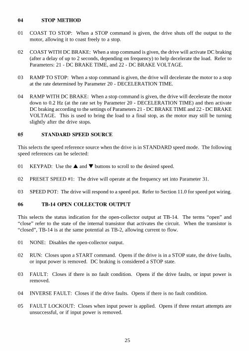
04 STOP METHOD
01 COAST TO STOP: When a STOP command is given, the drive shuts off the output to themotor, allowing it to coast freely to a stop.
02 COAST WITH DC BRAKE: When a stop command is given, the drive will activate DC braking(after a delay of up to 2 seconds, depending on frequency) to help decelerate the load. Refer toParameters: 21 - DC BRAKE TIME, and 22 - DC BRAKE VOLTAGE.
03 RAMP TO STOP: When a stop command is given, the drive will decelerate the motor to a stopat the rate determined by Parameter 20 - DECELERATION TIME.
04 RAMP WITH DC BRAKE: When a stop command is given, the drive will decelerate the motordown to 0.2 Hz (at the rate set by Parameter 20 - DECELERATION TIME) and then activateDC braking according to the settings of Parameters 21 - DC BRAKE TIME and 22 - DC BRAKEVOLTAGE. This is used to bring the load to a final stop, as the motor may still be turningslightly after the drive stops.
05 STANDARD SPEED SOURCE
This selects the speed reference source when the drive is in STANDARD speed mode. The followingspeed references can be selected:
01 KEYPAD: Use the and buttons to scroll to the desired speed.
02 PRESET SPEED #1: The drive will operate at the frequency set into Parameter 31.
03 SPEED POT: The drive will respond to a speed pot. Refer to Section 11.0 for speed pot wiring.
06 TB-14 OPEN COLLECTOR OUTPUT
This selects the status indication for the open-collector output at TB-14. The terms “open” and“close” refer to the state of the internal transistor that activates the circuit. When the transistor is“closed”, TB-14 is at the same potential as TB-2, allowing current to flow.
01 NONE: Disables the open-collector output.
02 RUN: Closes upon a START command. Opens if the drive is in a STOP state, the drive faults,or input power is removed. DC braking is considered a STOP state.
03 FAULT: Closes if there is no fault condition. Opens if the drive faults, or input power isremoved.
04 INVERSE FAULT: Closes if the drive faults. Opens if there is no fault condition.
05 FAULT LOCKOUT: Closes when input power is applied. Opens if three restart attempts areunsuccessful, or if input power is removed.
26
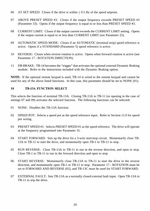
06 AT SET SPEED: Closes if the drive is within + 0.5 Hz of the speed setpoint.
07 ABOVE PRESET SPEED #3: Closes if the output frequency exceeds PRESET SPEED #3(Parameter 33). Opens if the output frequency is equal to or less than PRESET SPEED #3.
08 CURRENT LIMIT: Closes if the output current exceeds the CURRENT LIMIT setting. Opensif the output current is equal to or less than CURRENT LIMIT (see Parameter 25).
09 AUTOMATIC SPEED MODE: Closes if an AUTOMATIC (terminal strip) speed reference isactive. Opens if a STANDARD (Parameter 5) speed reference is active.
10 REVERSE: Closes when reverse rotation is active. Opens when forward rotation is active (seeParameter 17 - ROTATION DIRECTION).
11 DB BRAKE: TB-14 becomes the "trigger" that activates the optional external Dynamic Brakingmodule. Refer to the instructions included with the Dynamic Braking option.
NOTE: If the optional remote keypad is used, TB-14 is wired to the remote keypad and cannot beused for any of the above listed functions. In this case, this parameter should be set to NONE (01).
10 TB-13A FUNCTION SELECT
This selects the function of terminal TB-13A. Closing TB-13A to TB-11 (or opening in the case ofsettings 07 and 09) activates the selected function. The following functions can be selected:
01 NONE: Disables the TB-13A function.
02 SPEED POT: Selects a speed pot as the speed reference input. Refer to Section 11.0 for speedpot wiring.
03 PRESET SPEED #1: Selects PRESET SPEED #1 as the speed reference. The drive will operateat the frequency programmed into Parameter 31.
04 START FORWARD: Sets up the drive for a 3-wire start/stop circuit. Momentarily close TB-13A to TB-11 to start the drive, and momentarily open TB-1 to TB-11 to stop.
05 RUN REVERSE: Close TB-13A to TB-11 to run in the reverse direction, and open to stop.Close TB-1 to TB-11 to run in the forward direction and open to stop.
06 START REVERSE: Momentarily close TB-13A to TB-11 to start the drive in the reversedirection, and momentarily open TB-1 to TB-11 to stop. Parameter 17 - ROTATION must beset to FORWARD AND REVERSE (02), and TB-13C must be used for START FORWARD.
07 EXTERNAL FAULT: Sets TB-13A as a normally closed external fault input. Open TB-13A toTB-11 to trip the drive.
27
08 DB FAULT: Sets TB-13A as a dynamic braking fault input when used with the optional dynamicbraking module. When this input is activated by the dynamic braking module, the drive willtrip into a "dF" fault and the motor will coast to a stop. Refer to the instructions included withthe Dynamic Braking option.
09 AUXILIARY STOP: When TB-13A is opened with respect to TB-11, the drive will decelerateto a STOP (even if STOP METHOD is set to COAST) at the rate set into ACCEL/DECEL #2(Parameter 42).
10 ACCEL/DECEL #2: Selects the acceleration and deceleration time programmed into ACCEL/DECEL #2 (Parameter 42).
NOTE: If the optional remote keypad is used, functions 02, 04, 05, and 06 are disabled. Therefore,if this terminal is not being used for any of the other functions, it should be set to NONE (01).
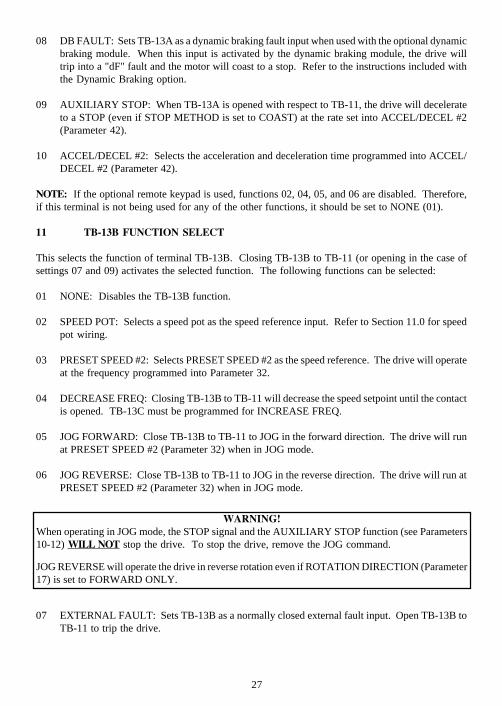
11 TB-13B FUNCTION SELECT
This selects the function of terminal TB-13B. Closing TB-13B to TB-11 (or opening in the case ofsettings 07 and 09) activates the selected function. The following functions can be selected:
01 NONE: Disables the TB-13B function.
02 SPEED POT: Selects a speed pot as the speed reference input. Refer to Section 11.0 for speedpot wiring.
03 PRESET SPEED #2: Selects PRESET SPEED #2 as the speed reference. The drive will operateat the frequency programmed into Parameter 32.
04 DECREASE FREQ: Closing TB-13B to TB-11 will decrease the speed setpoint until the contactis opened. TB-13C must be programmed for INCREASE FREQ.
05 JOG FORWARD: Close TB-13B to TB-11 to JOG in the forward direction. The drive will runat PRESET SPEED #2 (Parameter 32) when in JOG mode.
06 JOG REVERSE: Close TB-13B to TB-11 to JOG in the reverse direction. The drive will run atPRESET SPEED #2 (Parameter 32) when in JOG mode.
07 EXTERNAL FAULT: Sets TB-13B as a normally closed external fault input. Open TB-13B toTB-11 to trip the drive.
WARNING!When operating in JOG mode, the STOP signal and the AUXILIARY STOP function (see Parameters10-12) WILL NOT stop the drive. To stop the drive, remove the JOG command.
JOG REVERSE will operate the drive in reverse rotation even if ROTATION DIRECTION (Parameter17) is set to FORWARD ONLY.
28
08 DB FAULT: Used with the optional dynamic braking module. When this input is activated bythe dynamic braking module, the drive will trip into a "dF" fault and the motor will coast to astop. Refer to the instructions included with the Dynamic Braking option.
09 AUXILIARY STOP: When TB-13B is opened with respect to TB-11, the drive will decelerateto a STOP (even if STOP METHOD is set to COAST) at the rate set into ACCEL/DECEL #2(Parameter 42).
10 ACCEL/DECEL #2: Selects the acceleration and deceleration time programmed into Parameter42 - ACCEL/DECEL #2.
NOTE 1: If the drive is commanded to JOG while running, the drive will enter JOG mode and run atPRESET SPEED #2 (Parameter 32). When the JOG command is removed, the drive will STOP.
NOTE 2: If the optional remote keypad is used, functions 02 and 08 are disabled. Therefore, if thisterminal is not being used for any of the other functions, it should be set to NONE (01).
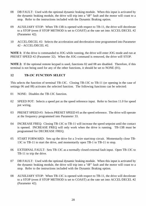
12 TB-13C FUNCTION SELECT
This selects the function of terminal TB-13C. Closing TB-13C to TB-11 (or opening in the case ofsettings 06 and 08) activates the selected function. The following functions can be selected:
01 NONE: Disables the TB-13C function.
02 SPEED POT: Selects a speed pot as the speed reference input. Refer to Section 11.0 for speedpot wiring.
03 PRESET SPEED #3: Selects PRESET SPEED #3 as the speed reference. The drive will operateat the frequency programmed into Parameter 33.
04 INCREASE FREQ: Closing TB-13C to TB-11 will increase the speed setpoint until the contactis opened. INCREASE FREQ will only work when the drive is running. TB-13B must beprogrammed for DECREASE FREQ.
05 START FORWARD: Sets up the drive for a 3-wire start/stop circuit. Momentarily close TB-13C to TB-11 to start the drive, and momentarily open TB-1 to TB-11 to stop.
06 EXTERNAL FAULT: Sets TB-13C as a normally closed external fault input. Open TB-13C toTB-11 to trip the drive.
07 DB FAULT: Used with the optional dynamic braking module. When this input is activated bythe dynamic braking module, the drive will trip into a "dF" fault and the motor will coast to astop. Refer to the instructions included with the Dynamic Braking option.
08 AUXILIARY STOP: When TB-13C is opened with respect to TB-11, the drive will decelerateto a STOP (even if STOP METHOD is set to COAST) at the rate set into ACCEL/DECEL #2(Parameter 42).
29
09 ACCEL/DECEL #2: Selects the acceleration and deceleration time programmed into ACCEL/DECEL #2 (Parameter 42).
NOTE: If the optional remote keypad is used, functions 02, 05, and 07 are disabled. Therefore, ifthis terminal is not being used for any of the other functions, it should be set to NONE (01).
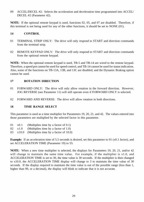
14 CONTROL
01 TERMINAL STRIP ONLY: The drive will only respond to START and direction commandsfrom the terminal strip.
02 REMOTE KEYPAD ONLY: The drive will only respond to START and direction commandsfrom the optional remote keypad.
NOTE: When the optional remote keypad is used, TB-5 and TB-14 are wired to the remote keypad.Therefore, a speed pot cannot be used for speed control, and TB-14 cannot be used for status indication.Also, some of the functions on TB-13A, 13B, and 13C are disabled, and the Dynamic Braking optioncannot be used.
17 ROTATION DIRECTION
01 FORWARD ONLY: The drive will only allow rotation in the forward direction. However,JOG REVERSE (see Parameter 11) will still operate even if FORWARD ONLY is selected.
02 FORWARD AND REVERSE: The drive will allow rotation in both directions.
18 TIME RANGE SELECT
This parameter is used as a time multiplier for Parameters 19, 20, 21, and 42. The values entered intothose parameters are multiplied by the selected factor in this parameter.
01 x0.1 (Multiplies time by a factor of 0.1)02 x1.0 (Multiplies time by a factor of 1.0)03 x10.0 (Multiplies time by a factor of 10.0)
Example: If an acceleration time of 5.5 seconds is desired, set this parameter to 01 (x0.1 factor), andset ACCELERATION TIME (Parameter 19) to 55.
NOTE: When a new time multiplier is selected, the displays for Parameters 19, 20, 21, and/or 42will change to maintain the same time value. For example, if the multiplier is x1.0, andACCELERATION TIME is set to 30, the time value is 30 seconds. If the multiplier is then changedto x10.0, the ACCELERATION TIME display will change to 3 to maintain the time value of 30seconds. If the display required to maintain the time value is out of the possible range (less than 1,higher than 99, or a decimal), the display will blink to indicate that it is not accurate.
30
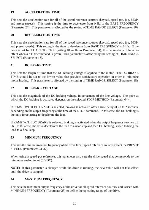
19 ACCELERATION TIME
This sets the acceleration rate for all of the speed reference sources (keypad, speed pot, jog, MOP,and preset speeds). This setting is the time to accelerate from 0 Hz to the BASE FREQUENCY(Parameter 27). This parameter is affected by the setting of TIME RANGE SELECT (Parameter 18).
20 DECELERATION TIME
This sets the deceleration rate for all of the speed reference sources (keypad, speed pot, jog, MOP,and preset speeds). This setting is the time to decelerate from BASE FREQUENCY to 0 Hz. If thedrive is set for COAST TO STOP (setting 01 or 02 in Parameter 04), this parameter will have noeffect when a STOP command is given. This parameter is affected by the setting of TIME RANGESELECT (Parameter 18).
21 DC BRAKE TIME
This sets the length of time that the DC braking voltage is applied to the motor. The DC BRAKETIME should be set to the lowest value that provides satisfactory operation in order to minimizemotor heating. This parameter is affected by the setting of TIME RANGE SELECT (Parameter 18).
22 DC BRAKE VOLTAGE
This sets the magnitude of the DC braking voltage, in percentage of the line voltage. The point atwhich the DC braking is activated depends on the selected STOP METHOD (Parameter 04):
If COAST WITH DC BRAKE is selected, braking is activated after a time delay of up to 2 seconds,depending on the output frequency at the time of the STOP command. In this case, the DC braking isthe only force acting to decelerate the load.
If RAMP WITH DC BRAKE is selected, braking is activated when the output frequency reaches 0.2Hz. In this case, the drive decelerates the load to a near stop and then DC braking is used to bring theload to a final stop.
23 MINIMUM FREQUENCY
This sets the minimum output frequency of the drive for all speed reference sources except the PRESETSPEEDS (Parameters 31-37).
When using a speed pot reference, this parameter also sets the drive speed that corresponds to theminimum analog input (0 VDC).
NOTE: If this parameter is changed while the drive is running, the new value will not take effectuntil the drive is stopped.
24 MAXIMUM FREQUENCY
This sets the maximum output frequency of the drive for all speed reference sources, and is used withMINIMUM FREQUENCY (Parameter 23) to define the operating range of the drive.
31
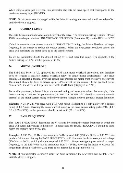
When using a speed pot reference, this parameter also sets the drive speed that corresponds to themaximum analog input (10 VDC).
NOTE: If this parameter is changed while the drive is running, the new value will not take effectuntil the drive is stopped.
25 CURRENT LIMIT
This sets the maximum allowable output current of the drive. The maximum setting is either 180% or150%, depending on whether LINE VOLTAGE SELECTION (Parameter 01) is set to HIGH or LOW.
If the load demands more current than the CURRENT LIMIT setting, the drive will reduce the outputfrequency in an attempt to reduce the output current. When the overcurrent condition passes, thedrive will accelerate the motor back up to the speed setpoint.
To set this parameter, divide the desired setting by 10 and enter that value. For example, if thedesired setting is 150%, set this parameter to 15.
26 MOTOR OVERLOAD
The SM-Basic Series is UL approved for solid state motor overload protection, and thereforedoes not require a separate thermal overload relay for single motor applications. The drivecontains an adjustable thermal overload circuit that protects the motor from excessive overcurrent.This circuit allows the drive to deliver up to 150% current for one minute. If the overload circuit“times out”, the drive will trip into an OVERLOAD fault (displayed as "PF").
To set this parameter, subtract 1 from the desired setting and enter that value. For example, if thedesired setting is 75%, set this parameter to 74. MOTOR OVERLOAD should be set to the ratio (inpercent) of the motor current rating to the drive current rating in order to properly protect the motor.
Example: A 2 HP, 230 Vac drive with a 6.8 Amp rating is operating a 1 HP motor with a currentrating of 4.0 Amps. Dividing the motor current rating by the drive current rating yields 59% (4.0 /6.8 = 0.59 = 59%), so this parameter should be set to 58 (58 + 1 = 59%).
27 BASE FREQUENCY
The BASE FREQUENCY determines the V/Hz ratio by setting the output frequency at which thedrive will output full voltage to the motor. In most cases, the BASE FREQUENCY should be set tomatch the motor’s rated frequency.
Example: A 230 Vac, 60 Hz motor requires a V/Hz ratio of 3.83 (230 V / 60 Hz = 3.83 V/Hz) toproduce full torque. Setting the BASE FREQUENCY to 60 Hz causes the drive to output full voltage(230 Vac) at 60 Hz, which yields the required 3.83 V/Hz. Output voltage is proportional to outputfrequency, so the 3.83 V/Hz ratio is maintained from 0 - 60 Hz, allowing the motor to produce fulltorque from about 2 Hz (below 2 Hz there is less torque due to slip) up to 60 Hz.
NOTE: If this parameter is changed while the drive is running, the new value will not take effectuntil the drive is stopped.

32
2 8 FIXED BOOST
FIXED BOOST increases starting torque by increasing the output voltage when operating below halfof the base frequency, which increases the V/Hz ratio. For better out-of-the-box performance, SCNSeries drives are shipped with a setting that is different from the factory default of 1%. Units rated0.25 to 1 HP are set to 5.3%, units rated 1.5 to 2 HP are set to 4.4%, and 3 HP units are set to 3.6%.
29 ACCELERATION BOOST
ACCELERATION BOOST helps accelerate high-inertia loads. During acceleration, the output voltageis increased to increase motor torque. Once the motor reaches the new speed setpoint, the boost isturned off and the output voltage returns to the normal value.
30 SLIP COMPENSATION
SLIP COMPENSATION is used to counteract changes in motor speed (slip) caused by changes inload. In a standard AC induction motor, the shaft speed decreases as load increases, and increases asload decreases. By increasing or decreasing the output frequency in response to an increasing ordecreasing load, the slip is counteracted and speed is maintained. Most standard NEMA B motorshave a 3% slip rating.
To set this parameter, multiply the desired setting by 10 and enter that value. For example, if asetting of 2.5% is desired, enter 25 into this parameter.
31 - 37 PRESET SPEED #1 - #7
Preset speeds are activated by contact closures between TB-11 and TB-13A, 13B, and 13C. The TB-13 terminals must be programmed as preset speed selects using Parameters 10-12.
NOTE 1: Preset speeds can operate below the frequency defined by the minimum frequency parameter(Parameter 23).
Refer to the table below for activation of the preset speeds using the TB-13 terminals.
SPEED # TB - 13A TB - 13B TB - 13C
1 CLOSED OPEN OPEN
2 OPEN CLOSED OPEN
3 OPEN OPEN CLOSED
4 CLOSED CLOSED OPEN
5 CLOSED OPEN CLOSED
6 OPEN CLOSED CLOSED
7 CLOSED CLOSED CLOSED
33
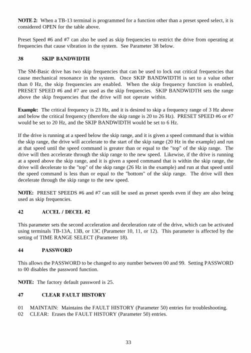
NOTE 2: When a TB-13 terminal is programmed for a function other than a preset speed select, it isconsidered OPEN for the table above.
Preset Speed #6 and #7 can also be used as skip frequencies to restrict the drive from operating atfrequencies that cause vibration in the system. See Parameter 38 below.
38 SKIP BANDWIDTH
The SM-Basic drive has two skip frequencies that can be used to lock out critical frequencies thatcause mechanical resonance in the system. Once SKIP BANDWIDTH is set to a value otherthan 0 Hz, the skip frequencies are enabled. When the skip frequency function is enabled,PRESET SPEED #6 and #7 are used as the skip frequencies. SKIP BANDWIDTH sets the rangeabove the skip frequencies that the drive will not operate within.
Example: The critical frequency is 23 Hz, and it is desired to skip a frequency range of 3 Hz aboveand below the critical frequency (therefore the skip range is 20 to 26 Hz). PRESET SPEED #6 or #7would be set to 20 Hz, and the SKIP BANDWIDTH would be set to 6 Hz.
If the drive is running at a speed below the skip range, and it is given a speed command that is withinthe skip range, the drive will accelerate to the start of the skip range (20 Hz in the example) and runat that speed until the speed command is greater than or equal to the "top" of the skip range. Thedrive will then accelerate through the skip range to the new speed. Likewise, if the drive is runningat a speed above the skip range, and it is given a speed command that is within the skip range, thedrive will decelerate to the "top" of the skip range (26 Hz in the example) and run at that speed untilthe speed command is less than or equal to the "bottom" of the skip range. The drive will thendecelerate through the skip range to the new speed.
NOTE: PRESET SPEEDS #6 and #7 can still be used as preset speeds even if they are also beingused as skip frequencies.
42 ACCEL / DECEL #2
This parameter sets the second acceleration and deceleration rate of the drive, which can be activatedusing terminals TB-13A, 13B, or 13C (Parameter 10, 11, or 12). This parameter is affected by thesetting of TIME RANGE SELECT (Parameter 18).
44 PASSWORD
This allows the PASSWORD to be changed to any number between 00 and 99. Setting PASSWORDto 00 disables the password function.
NOTE: The factory default password is 25.
47 CLEAR FAULT HISTORY
01 MAINTAIN: Maintains the FAULT HISTORY (Parameter 50) entries for troubleshooting.02 CLEAR: Erases the FAULT HISTORY (Parameter 50) entries.
34
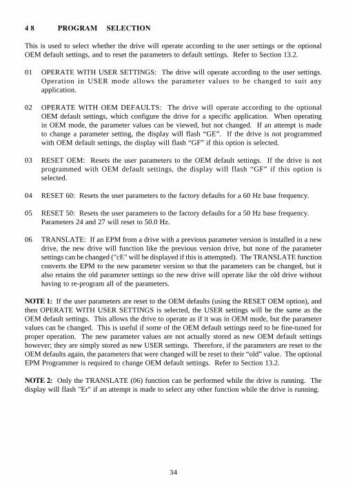
4 8 PROGRAM SELECTION
This is used to select whether the drive will operate according to the user settings or the optionalOEM default settings, and to reset the parameters to default settings. Refer to Section 13.2.
01 OPERATE WITH USER SETTINGS: The drive will operate according to the user settings.Operation in USER mode allows the parameter values to be changed to suit anyapplication.
02 OPERATE WITH OEM DEFAULTS: The drive will operate according to the optionalOEM default settings, which configure the drive for a specific application. When operatingin OEM mode, the parameter values can be viewed, but not changed. If an attempt is madeto change a parameter setting, the display will flash “GE”. If the drive is not programmedwith OEM default settings, the display will flash “GF” if this option is selected.
03 RESET OEM: Resets the user parameters to the OEM default settings. If the drive is notprogrammed with OEM default settings, the display will flash “GF” if this option isselected.
04 RESET 60: Resets the user parameters to the factory defaults for a 60 Hz base frequency.
05 RESET 50: Resets the user parameters to the factory defaults for a 50 Hz base frequency.Parameters 24 and 27 will reset to 50.0 Hz.
06 TRANSLATE: If an EPM from a drive with a previous parameter version is installed in a newdrive, the new drive will function like the previous version drive, but none of the parametersettings can be changed ("cE" will be displayed if this is attempted). The TRANSLATE functionconverts the EPM to the new parameter version so that the parameters can be changed, but italso retains the old parameter settings so the new drive will operate like the old drive withouthaving to re-program all of the parameters.
NOTE 1: If the user parameters are reset to the OEM defaults (using the RESET OEM option), andthen OPERATE WITH USER SETTINGS is selected, the USER settings will be the same as theOEM default settings. This allows the drive to operate as if it was in OEM mode, but the parametervalues can be changed. This is useful if some of the OEM default settings need to be fine-tuned forproper operation. The new parameter values are not actually stored as new OEM default settingshowever; they are simply stored as new USER settings. Therefore, if the parameters are reset to theOEM defaults again, the parameters that were changed will be reset to their “old” value. The optionalEPM Programmer is required to change OEM default settings. Refer to Section 13.2.
NOTE 2: Only the TRANSLATE (06) function can be performed while the drive is running. Thedisplay will flash "Er" if an attempt is made to select any other function while the drive is running.

35
5 0 FAULT HISTORY
The FAULT HISTORY stores the last eight faults that tripped the drive. Refer to Section 16.0 -TROUBLESHOOTING for a list of the faults and possible causes.
Use the and buttons to scroll through the fault entries. The faults are stored from newest tooldest, with the first fault shown being the most recent.
The display will read “_ _” if the FAULT HISTORY does not contain any fault messages.
51 SOFTWARE VERSION
This displays the software version number for the control board software. This information is usefulwhen contacting the factory for programming or troubleshooting assistance.
The software version is displayed in two parts which alternate. The first part is the software version,and the second part is the revision number. For example, if the display flashes "72" and "02", thisindicates that the drive contains the second revision of version 72 software.
52 DC BUS VOLTAGE
This displays the DC bus voltage in percent of nominal. Nominal DC bus voltage is determined bymultiplying the drive’s nameplate input voltage rating by 1.4.
53 MOTOR VOLTAGE
This displays the output voltage in percent of the drive’s nameplate output voltage rating.
54 MOTOR LOAD
This displays the motor load in percent of the drive’s output current rating.
55 SPEED POT INPUT
This displays the level of the speed pot input signal at TB-5. A reading of 100% indicates that themaximum speed pot signal is present at TB-5.
NOTE: Paramaters 52-55 can display values greater than 99. If the value is greater than 99, thedisplay will alternate between "1 -" or "2 -" (for one hundred or two hundred) and the rest of thevalue. For example, if MOTOR LOAD is 137%, the display will alternate between "1 -" and "37".

36
NOTE: FCLIM is an abbreviation for Fast Current Limit.
FCLIM
OUTPUTFAULT
58 KEYPAD AND PROTECTION STATUS
This indicate the status of the buttons on the keypad, and the status of the protective circuitry in thedrive, using the horizontal segments of the LED display. An illuminated segment indicates that theparticular button is pressed, or the protective circuit is active.
TB-1 TB-13A
TB-13B TB-14
TB-13C
FACTORYRESERVED
5 7 TERMINAL STRIP STATUS
This indicate the status of several terminals using the vertical segments of the LED display. Anilluminated segment indicates that the particular terminal is closed to TB-2.
37
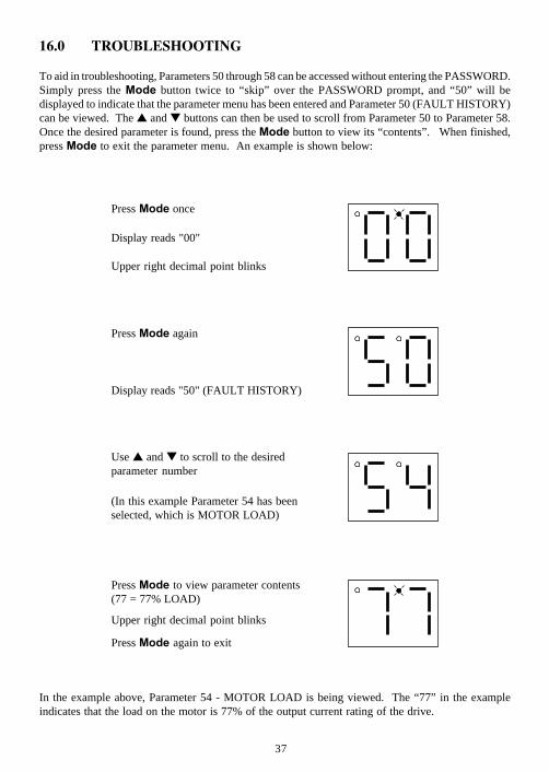
Press to view parameter contents(77 = 77% LOAD)
Press again to exit
Upper right decimal point blinks
Press once
Upper right decimal point blinks
Display reads "00"
Press again
Display reads "50" (FAULT HISTORY)
Use and to scroll to the desiredparameter number
(In this example Parameter 54 has beenselected, which is MOTOR LOAD)
16.0 TROUBLESHOOTING
To aid in troubleshooting, Parameters 50 through 58 can be accessed without entering the PASSWORD.Simply press the button twice to “skip” over the PASSWORD prompt, and “50” will bedisplayed to indicate that the parameter menu has been entered and Parameter 50 (FAULT HISTORY)can be viewed. The and buttons can then be used to scroll from Parameter 50 to Parameter 58.Once the desired parameter is found, press the button to view its “contents”. When finished,press to exit the parameter menu. An example is shown below:
In the example above, Parameter 54 - MOTOR LOAD is being viewed. The “77” in the exampleindicates that the load on the motor is 77% of the output current rating of the drive.
38
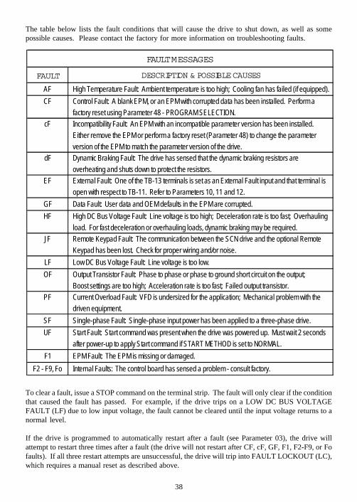
The table below lists the fault conditions that will cause the drive to shut down, as well as somepossible causes. Please contact the factory for more information on troubleshooting faults.
To clear a fault, issue a STOP command on the terminal strip. The fault will only clear if the conditionthat caused the fault has passed. For example, if the drive trips on a LOW DC BUS VOLTAGEFAULT (LF) due to low input voltage, the fault cannot be cleared until the input voltage returns to anormal level.
If the drive is programmed to automatically restart after a fault (see Parameter 03), the drive willattempt to restart three times after a fault (the drive will not restart after CF, cF, GF, F1, F2-F9, or Fofaults). If all three restart attempts are unsuccessful, the drive will trip into FAULT LOCKOUT (LC),which requires a manual reset as described above.
FAULT MESSAGES
FAULT
AF High Temperature Fault: Ambient temperature is too high; Cooling fan has failed (if equipped).CF Control Fault: A blank EPM, or an EPM with corrupted data has been installed. Perform a
factory reset using Parameter 48 - PROGRAM SELECTION.cF Incompatibility Fault: An EPM with an incompatible parameter version has been installed.
Either remove the EPM or perform a factory reset (Parameter 48) to change the parameterversion of the EPM to match the parameter version of the drive.
dF Dynamic Braking Fault: The drive has sensed that the dynamic braking resistors areoverheating and shuts down to protect the resistors.
EF External Fault: One of the TB-13 terminals is set as an External Fault input and that terminal isopen with respect to TB-11. Refer to Parameters 10, 11 and 12.
GF Data Fault: User data and OEM defaults in the EPM are corrupted.HF High DC Bus Voltage Fault: Line voltage is too high; Deceleration rate is too fast; Overhauling
load. For fast deceleration or overhauling loads, dynamic braking may be required.JF Remote Keypad Fault: The communication between the SCN drive and the optional Remote
Keypad has been lost. Check for proper wiring and/or noise.LF Low DC Bus Voltage Fault: Line voltage is too low.OF Output Transistor Fault: Phase to phase or phase to ground short circuit on the output;
Boost settings are too high; Acceleration rate is too fast; Failed output transistor.PF Current Overload Fault: VFD is undersized for the application; Mechanical problem with the
driven equipment.SF Single-phase Fault: Single-phase input power has been applied to a three-phase drive.UF Start Fault: Start command was present when the drive was powered up. Must wait 2 seconds
after power-up to apply Start command if START METHOD is set to NORMAL.F1 EPM Fault: The EPM is missing or damaged.
F2 - F9, Fo Internal Faults: The control board has sensed a problem - consult factory.
DESCRIPTION & POSSIBLE CAUSES
39
17.0 SM-Basic DISPLAY MESSAGES
The following describes the various displays and messages that can appear on the SCN drive.
17.1 SPEED DISPLAY
If the drive is in a STOP state (indicated by "- -" on the display), and the keypad speed command ischanged, the display will show the commanded speed, and the upper left decimal point will turn onsolid. About five seconds after a change is made, the display will begin to alternate between thecommanded speed value and the "- -" display. If the button is pressed, the display will stopalternating and show the "- -" display only.
When the drive is given a START command, the displayed speed will start increasing as the driveaccelerates up to the commanded speed. If the keypad speed command is changed while the drive isrunning, the display will show the commanded speed rather than the actual speed, until the actualspeed reaches the commanded speed.
If the keypad speed command is changed faster than the drive can accelerate or decelerate, the upperleft decimal point will blink to indicate that the the drive is accelerating or decelerating to the newspeed. Once the actual speed reaches the commanded speed, the upper left decimal point will turn onsolid for 5 seconds and then turn off to indicate that the commanded speed has been reached, and thatthe display is now showing the actual speed.
17.2 CHANGING THE SPEED REFERENCE SOURCE
When the speed source is changed while the drive is running, the display will flash the message forthe new speed source to indicate that the new speed source is active. Also, if the drive is beingcontrolled from a speed source other than the and buttons (speed pot, preset speed, etc), and oneof the or buttons is pressed, the display will flash the present speed source message to indicatethat the and buttons are invalid.
Example 1: The drive is running and the present speed source is the keypad. TB-13A is programmedto select a speed pot signal as the speed source. When TB-13A is closed to TB-11, the display willflash “EU” to indicate that the speed source has changed to the speed pot signal. If the contactbetween TB-13A and TB-11 is opened, the display will flash “CP” to indicate that the speed sourcehas changed back to the and buttons.
Example 2: The speed source is a speed pot. If the or button is pushed, the display will flash“EU” to indicate that the present speed source is the speed pot and that the and buttons areinvalid.
Refer to the table below for the possible speed reference source displays:
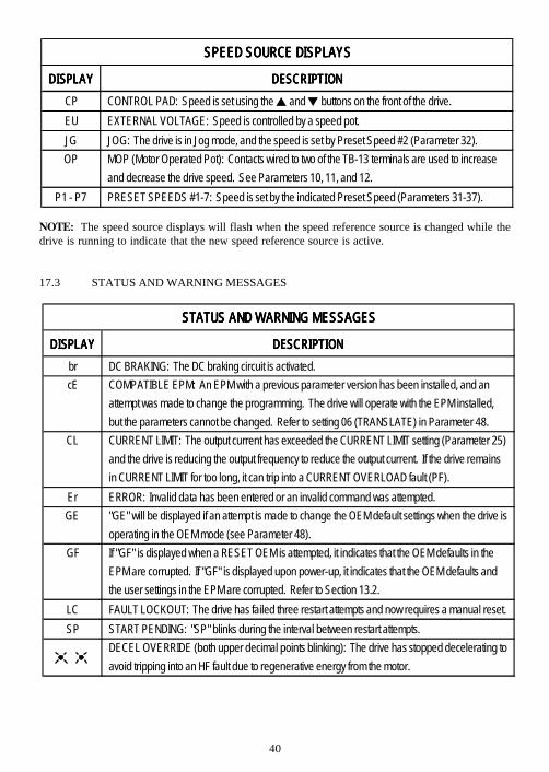
40
NOTE: The speed source displays will flash when the speed reference source is changed while thedrive is running to indicate that the new speed reference source is active.
17.3 STATUS AND WARNING MESSAGES
SPEED SOURCE DISPLAYSSPEED SOURCE DISPLAYSSPEED SOURCE DISPLAYSSPEED SOURCE DISPLAYS
DISPLAYDISPLAYDISPLAYDISPLAY DESCRIPTIONDESCRIPTIONDESCRIPTIONDESCRIPTIONCP CONTROL PAD: Speed is set using the and buttons on the front of the drive.EU EXTERNAL VOLTAGE: Speed is controlled by a speed pot.JG JOG: The drive is in Jog mode, and the speed is set by Preset Speed #2 (Parameter 32).OP MOP (Motor Operated Pot): Contacts wired to two of the TB-13 terminals are used to increase
and decrease the drive speed. See Parameters 10, 11, and 12.P1 - P7 PRESET SPEEDS #1-7: Speed is set by the indicated Preset Speed (Parameters 31-37).
DISPLAYDISPLAYDISPLAYDISPLAY DESCRIPTIONDESCRIPTIONDESCRIPTIONDESCRIPTIONbr DC BRAKING: The DC braking circuit is activated.cE COMPATIBLE EPM: An EPM with a previous parameter version has been installed, and an
attempt was made to change the programming. The drive will operate with the EPM installed,but the parameters cannot be changed. Refer to setting 06 (TRANSLATE) in Parameter 48.
CL CURRENT LIMIT: The output current has exceeded the CURRENT LIMIT setting (Parameter 25)and the drive is reducing the output frequency to reduce the output current. If the drive remainsin CURRENT LIMIT for too long, it can trip into a CURRENT OVERLOAD fault (PF).
Er ERROR: Invalid data has been entered or an invalid command was attempted.GE "GE" will be displayed if an attempt is made to change the OEM default settings when the drive is
operating in the OEM mode (see Parameter 48).GF If "GF" is displayed when a RESET OEM is attempted, it indicates that the OEM defaults in the
EPM are corrupted. If "GF" is displayed upon power-up, it indicates that the OEM defaults andthe user settings in the EPM are corrupted. Refer to Section 13.2.
LC FAULT LOCKOUT: The drive has failed three restart attempts and now requires a manual reset.SP START PENDING: "SP" blinks during the interval between restart attempts.
DECEL OVERRIDE (both upper decimal points blinking): The drive has stopped decelerating toavoid tripping into an HF fault due to regenerative energy from the motor.
STATUS AND WARNING MESSAGESSTATUS AND WARNING MESSAGESSTATUS AND WARNING MESSAGESSTATUS AND WARNING MESSAGES
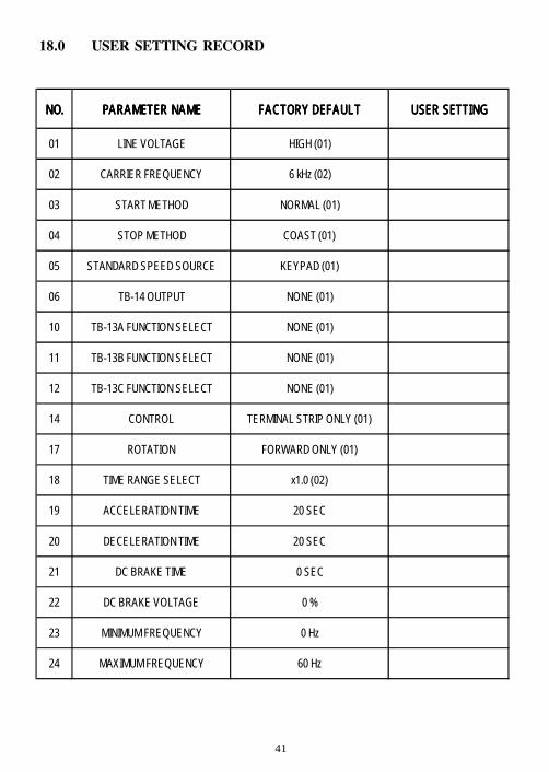
41
18.0 USER SETTING RECORD
NO.NO.NO.NO. PARAMETER NAMEPARAMETER NAMEPARAMETER NAMEPARAMETER NAME FACTORY DEFAULTFACTORY DEFAULTFACTORY DEFAULTFACTORY DEFAULT USER SETTINGUSER SETTINGUSER SETTINGUSER SETTING
01 LINE VOLTAGE HIGH (01)
02 CARRIER FREQUENCY 6 kHz (02)
03 START METHOD NORMAL (01)
04 STOP METHOD COAST (01)
05 STANDARD SPEED SOURCE KEYPAD (01)
06 TB-14 OUTPUT NONE (01)
10 TB-13A FUNCTION SELECT NONE (01)
11 TB-13B FUNCTION SELECT NONE (01)
12 TB-13C FUNCTION SELECT NONE (01)
14 CONTROL TERMINAL STRIP ONLY (01)
17 ROTATION FORWARD ONLY (01)
18 TIME RANGE SELECT x1.0 (02)
19 ACCELERATION TIME 20 SEC
20 DECELERATION TIME 20 SEC
21 DC BRAKE TIME 0 SEC
22 DC BRAKE VOLTAGE 0 %
23 MINIMUM FREQUENCY 0 Hz
24 MAXIMUM FREQUENCY 60 Hz
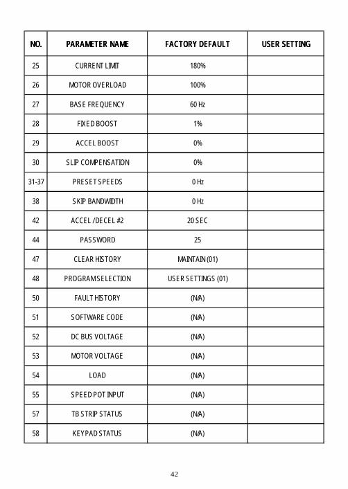
42
NO.NO.NO.NO. PARAMETER NAMEPARAMETER NAMEPARAMETER NAMEPARAMETER NAME FACTORY DEFAULTFACTORY DEFAULTFACTORY DEFAULTFACTORY DEFAULT USER SETTINGUSER SETTINGUSER SETTINGUSER SETTING
25 CURRENT LIMIT 180%
26 MOTOR OVERLOAD 100%
27 BASE FREQUENCY 60 Hz
28 FIXED BOOST 1%
29 ACCEL BOOST 0%
30 SLIP COMPENSATION 0%
31-37 PRESET SPEEDS 0 Hz
38 SKIP BANDWIDTH 0 Hz
42 ACCEL / DECEL #2 20 SEC
44 PASSWORD 25
47 CLEAR HISTORY MAINTAIN (01)
48 PROGRAM SELECTION USER SETTINGS (01)
50 FAULT HISTORY (N/A)
51 SOFTWARE CODE (N/A)
52 DC BUS VOLTAGE (N/A)
53 MOTOR VOLTAGE (N/A)
54 LOAD (N/A)
55 SPEED POT INPUT (N/A)
57 TB STRIP STATUS (N/A)
58 KEYPAD STATUS (N/A)

Service Dept. FAX (262)-377-0090
4/00