
Variable-area flowmeter - Forbes Marshall · PDF fileVariable-area flowmeter • Complete...
16
H250 Technical Datasheet Variable-area flowmeter • Complete family with different displays • Local indication without the need for auxiliary power • Measurement in all flow directions • Rugged design for extreme operating conditions • Flexible and can be adapted to meet customer-specific requirements • Special food & pharmaceutical models
Transcript of Variable-area flowmeter - Forbes Marshall · PDF fileVariable-area flowmeter • Complete...

H250 Technical Datasheet
Variable-area flowmeter
• Complete family with different displays
• Local indication without the need for auxiliary power
• Measurement in all flow directions
• Rugged design for extreme operating conditions
• Flexible and can be adapted to meet customer-specific requirements
• Special food & pharmaceutical models
H250 nnnnnnnnnnnnnnnnnnnnnnnnnnnnnnnnnnnnnnnnnnnnnnnnnnn
www.krohne.com 2
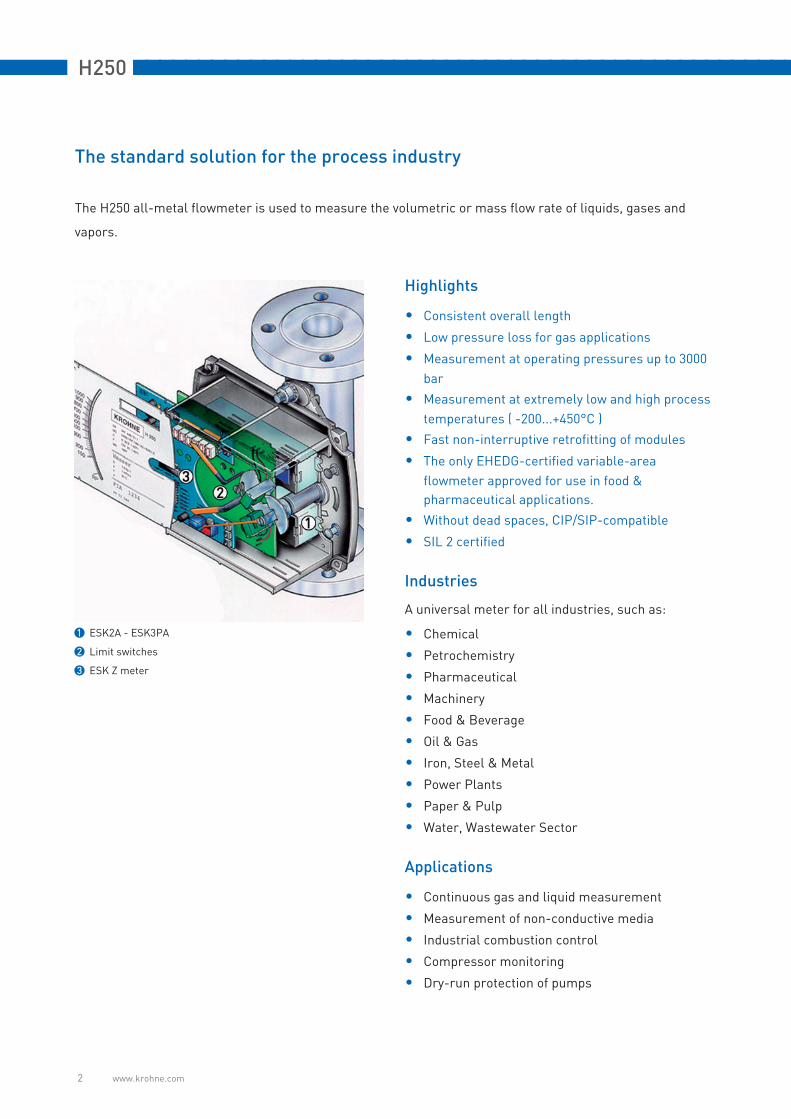
The standard solution for the process industry
The H250 all-metal flowmeter is used to measure the volumetric or mass flow rate of liquids, gases and
vapors.
Highlights
• Consistent overall length
• Low pressure loss for gas applications
• Measurement at operating pressures up to 3000
bar
• Measurement at extremely low and high process
temperatures ( -200...+450°C )
• Fast non-interruptive retrofitting of modules
• The only EHEDG-certified variable-area
flowmeter approved for use in food &
pharmaceutical applications.
• Without dead spaces, CIP/SIP-compatible
• SIL 2 certified
Industries
A universal meter for all industries, such as:
• Chemical
• Petrochemistry
• Pharmaceutical
• Machinery
• Food & Beverage
• Oil & Gas
• Iron, Steel & Metal
• Power Plants
• Paper & Pulp
• Water, Wastewater Sector
Applications
• Continuous gas and liquid measurement
• Measurement of non-conductive media
• Industrial combustion control
• Compressor monitoring
• Dry-run protection of pumps
1 ESK2A - ESK3PA
2 Limit switches
3 ESK Z meter

nnnnnnnnnnnnnnnnnnnnnnnnnnnnnnnnnnnnnnnnnnnnnnnnnnn H250
www.krohne.com 3
The all-metal product family
H250 variable-area flowmeters
For flow rates up to 120 m3/h water and 2800 m3/h air
1 H250/RR/M9
• Local indication without the need for auxiliary power
• max. 2 limit switches, type NAMUR, NAMUR intrinsically safe or 3-wire open collector
• 2-wire current output 4...20 mA, HARTTM or Profibus communication
• 6-digit flow totalizer (non-Ex)
2 H250/RR/M10
• Explosion proof terminal housing Ex d
• 2 digital adjustable limit switches, 2-wire open collector or type NAMUR
• 2-wire current output 4...20 mA, HARTTM communication
• Pulse output up to 10Hz (also for electromechanical counters)
• 12-digit flow totalizer with external reset (batch operation)
3 H250/RR/M8M
• Slim design allows high packing density
• Local indication without the need for auxiliary power
• 2 limit switches, 2-wire type NAMUR or NAMUR intrinsically safe
4 H250/RR/M8E
• Slim design allows high packing density
• 2-wire current output 4...20 mA, HARTTM communication
For flow rates greater than 0.15 l/h water and 1.6 l/h air:
DK metal variable-area flowmeters
1 DK32 - local indicator with max two limit switches, horizontal process connection
2 DK34 - local indicator with max. two limit switches, vertical process connection
3 DK37/M8M - large and local indicator with max. two limit switches
4 DK37/M8E - bar chart display and current output 4...20 mA, HARTTM communication

H250 nnnnnnnnnnnnnnnnnnnnnnnnnnnnnnnnnnnnnnnnnnnnnnnnnnn
www.krohne.com 4
Technical Data
Nominal sizes, DIN
Nominal sizes, ASME
Weights
Field of application Flow measurement of liquids, gases and vapors
Operating method / measuring principle Float measuring principle
Measuring accuracy H250 /RR /HC /F ± 1.6% to VDI / VDE Code 3513, Sheet 2
Measuring accuracy H250/C (Ceramic, PTFE) ± 2.5% to VDI / VDE Code 3513, Sheet 2
Inlet run ≥ 5 x DN
Outlet run ≥ 3 x DN
Operating pressure PS to 3000 bar as per Directive 97/23/ EC dated 29 April 1999
Test pressure PT in accordance with Pressure Equipment Directive 97/23/EC or AD 2000-HP30
Min. required operating pressure twice pressure loss (see measuring ranges)
Float damping recommended for gas measurement:
DN15 / ½" Operating pressure less than 0.3 bar
DN25 / 1" Operating pressure less than 0.3 bar
DN50 / 2" Operating pressure less than 0.2 bar
DN80 / 3" Operating pressure less than 0.2 bar
DN100 / 4" on request
Bolts Tightening torques
Nominal sizes as per EN 1092-1 Quantity x size SI [Nm] Imp [ft lbs]
DN15 PN40 4 x M12 9.8 7.1
DN25 PN40 4 x M12 21 15
DN50 PN40 4 x M16 57 41
DN80 PN16 8 x M16 47 34
DN100 PN16 8 x M16 67 48
Bolts Tightening torques
Normal sizes as per ASME B 16.5 Quantity x size SI [Nm] Imp [ft lbs]
½" 150 lbs / 300 lbs 4 x ½" 5.2 3.8
1" 150 lbs / 300 lbs 4 x ½" 10 7.2
2" 150 lbs / 300 lbs 4 x 5/8" 41 30
3" 150 lbs / 300 lbs 4 x 5/8" 70 51
4" 150 lbs / 300 lbs 8 x 5/8" 50 36
Weights [kg] H250 with heating H250/C Screw connection
Nominaldiameter
EN 1092-1 Flange connection Ermeto 12 connection
EN 1092-1 ASME B 16.5 / 150 lbs
ASME B 16.5 / 300 lbs
DIN 11864-1
DN15 / ½" 3.5 5.55 5.7 3.5 3.2 3.5 2
DN25 / 1" 5 7.45 7.6 5 5.2 6.8 3.5
DN50 / 2" 8.2 11.15 11.3 10 10 11 5
DN80 / 3" 12.2 14.75 14.9 13 13 15 7.6
DN100 / 4" 14 17.35 17.5 15 16 17 10.3
nnnnnnnnnnnnnnnnnnnnnnnnnnnnnnnnnnnnnnnnnnnnnnnnnnn H250
www.krohne.com 5
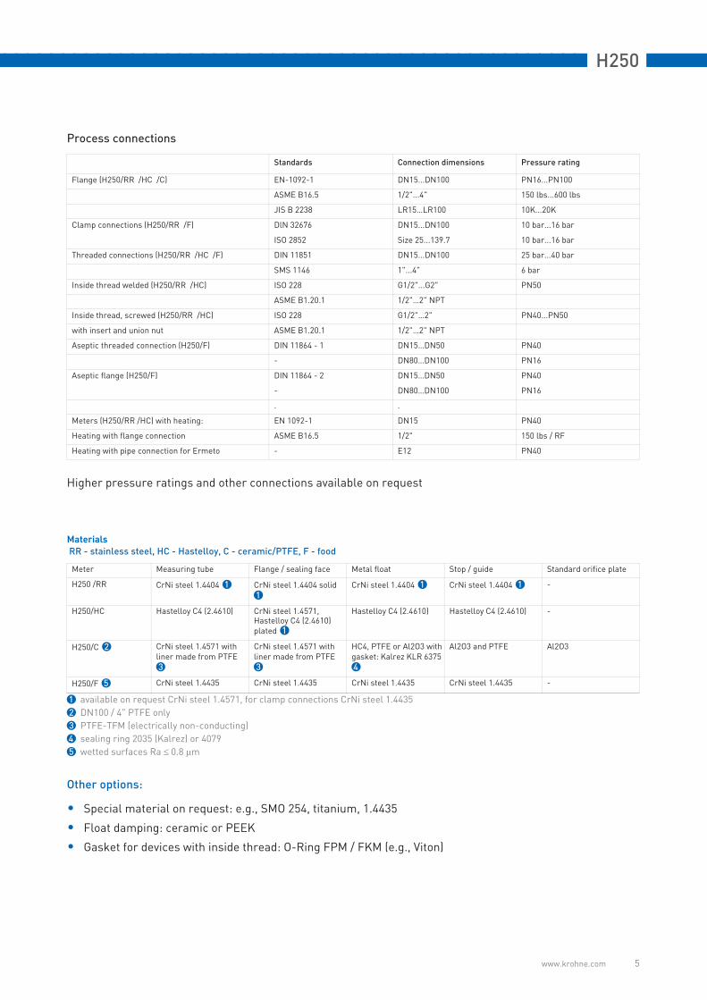
Process connections
Higher pressure ratings and other connections available on request
Materials
RR - stainless steel, HC - Hastelloy, C - ceramic/PTFE, F - food
Other options:
• Special material on request: e.g., SMO 254, titanium, 1.4435
• Float damping: ceramic or PEEK
• Gasket for devices with inside thread: O-Ring FPM / FKM (e.g., Viton)
Standards Connection dimensions Pressure rating
Flange (H250/RR /HC /C) EN-1092-1 DN15...DN100 PN16...PN100
ASME B16.5 1/2"...4" 150 lbs...600 lbs
JIS B 2238 LR15…LR100 10K...20K
Clamp connections (H250/RR /F) DlN 32676 DN15...DN100 10 bar...16 bar
ISO 2852 Size 25...139.7 10 bar...16 bar
Threaded connections (H250/RR /HC /F) DIN 11851 DN15...DN100 25 bar...40 bar
SMS 1146 1"...4" 6 bar
Inside thread welded (H250/RR /HC) ISO 228 G1/2"...G2" PN50
ASME B1.20.1 1/2"…2" NPT
Inside thread, screwed (H250/RR /HC) ISO 228 G1/2"…2" PN40...PN50
with insert and union nut ASME B1.20.1 1/2"…2" NPT
Aseptic threaded connection (H250/F) DIN 11864 - 1 DN15…DN50 PN40
- DN80…DN100 PN16
Aseptic flange (H250/F) DIN 11864 - 2 DN15…DN50 PN40
- DN80…DN100 PN16
. .
Meters (H250/RR /HC) with heating: EN 1092-1 DN15 PN40
Heating with flange connection ASME B16.5 1/2" 150 lbs / RF
Heating with pipe connection for Ermeto - E12 PN40
Meter Measuring tube Flange / sealing face Metal float Stop / guide Standard orifice plate
H250 /RR CrNi steel 1.4404 1 CrNi steel 1.4404 solid1
CrNi steel 1.4404 1 CrNi steel 1.4404 1 -
H250/HC Hastelloy C4 (2.4610) CrNi steel 1.4571, Hastelloy C4 (2.4610) plated 1
Hastelloy C4 (2.4610) Hastelloy C4 (2.4610) -
H250/C 2 CrNi steel 1.4571 with liner made from PTFE3
CrNi steel 1.4571 with liner made from PTFE3
HC4, PTFE or Al2O3 with gasket: Kalrez KLR 63754
Al2O3 and PTFE Al2O3
H250/F 5 CrNi steel 1.4435 CrNi steel 1.4435 CrNi steel 1.4435 CrNi steel 1.4435 -
1 available on request CrNi steel 1.4571, for clamp connections CrNi steel 1.4435
2 DN100 / 4" PTFE only
3 PTFE-TFM (electrically non-conducting)
4 sealing ring 2035 (Kalrez) or 4079
5 wetted surfaces Ra ≤ 0.8 μm

H250 nnnnnnnnnnnnnnnnnnnnnnnnnnnnnnnnnnnnnnnnnnnnnnnnnnn
www.krohne.com 6
Technical data for indicators M8 M9 M10
M8 indicator
M8M limit switch
Clamp connection 2.5mm2
Limit switches SC3,5-N0-Y SJ3,5-SN SJ3,5-S1N
Type 2-wire NAMUR 2-wire NAMUR 2-wire NAMUR
Switch configuration Normally closed Normally closed Normally open
Nominal voltage U0 8 VDC 8 VDC 8 VDC
Pointer shaft not read ≥3 mA ≥3 mA ≤1 mA
Pointer shaft read ≤1 mA ≤1 mA ≥3 mA
M8E current output
Cable fitting M16 x 1.5
Cable diameter 8…10 mm
Clamp connection 4 mm2
Measurement signal 4...20 mA for 0…100% flow value Two-wire technology
Power supply 14.8...30 VDC
Min. power supply with HARTTM 20.5 VDC
Effect of supply power < 0.1%
External resistance dependence < 0.1%
Effect of temperature < 10uA / K
Max. external resistance / load impedance 640 ohms (30 VDC)
Min. load with HARTTM 250 ohms
M8E HART
M8E HARTTM parameter configuration
Name of manufacturer (code) KROHNE Messtechnik (69)
Name of model M8E (230)
HARTTM protocol revision 5.1
Device revision 1
Physical layer FSK
Device category Transmitter
M8E process variable
M8E process variable flow Values [%] Signal output [mA]
Over range +105 (± 1%) 20.64...20.96
Device error detection > 110 > 21.60
Maximum 112.5 22
Multi-drop operation - 4.5
nnnnnnnnnnnnnnnnnnnnnnnnnnnnnnnnnnnnnnnnnnnnnnnnnnn H250
www.krohne.com 7
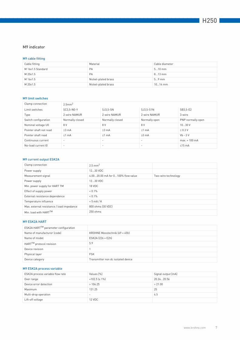
M9 indicator
M9 cable fitting
Cable fitting Material Cable diameter
M 16x1.5 Standard PA 5...10 mm
M 20x1.5 PA 8...13 mm
M 16x1.5 Nickel-plated brass 5...9 mm
M 20x1.5 Nickel-plated brass 10...14 mm
M9 limit switches
Clamp connection 2.5mm2
Limit switches SC3,5-N0-Y SJ3,5-SN SJ3,5-S1N SB3,5-E2
Type 2-wire NAMUR 2-wire NAMUR 2-wire NAMUR 3-wire
Switch configuration Normally closed Normally closed Normally open PNP normally open
Nominal voltage U0 8 V 8 V 8 V 10...30 V
Pointer shaft not read ≥3 mA ≥3 mA ≤1 mA ≤ 0.3 V
Pointer shaft read ≤1 mA ≤1 mA ≥3 mA Vb - 3 V
Continuous current - - - max. = 100 mA
No-load current I0 - - - ≤15 mA
M9 current output ESK2A
Clamp connection 2.5 mm2
Power supply 12...30 VDC
Measurement signal 4.00...20.00 mA for 0...100% flow value Two-wire technology
Power supply 12...30 VDC
Min. power supply for HART TM 18 VDC
Effect of supply power < 0.1%
External resistance dependence < 0.1%
Temperature influence < 5 mA / K
Max. external resistance / load impedance 800 ohms (30 VDC)
Min. load with HARTTM 250 ohms
M9 ESK2A HART
ESK2A HARTTM parameter configuration
Name of manufacturer (code) KROHNE Messtechnik (69 = 45h)
Name of model ESK2A (226 = E2h)
HARTTM protocol revision 5.9
Device revision 1
Physical layer FSK
Device category Transmitter non dc isolated device
M9 ESK2A process variable
ESK2A process variable flow rate Values [%] Signal output [mA]
Over range +102.5 (± 1%) 20.24...20.56
Device error detection > 106.25 > 21.00
Maximum 131.25 25
Multi-drop operation - 4.5
Lift-off voltage 12 VDC
H250 nnnnnnnnnnnnnnnnnnnnnnnnnnnnnnnnnnnnnnnnnnnnnnnnnnn
www.krohne.com 8
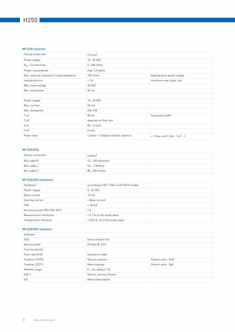
M9 ESK totalizer
Clamp connection 2.5 mm2
Power supply 10...30 VDC
Rext. Current loop 0...600 ohms
Power consumption max. 2.5 watts
Max. external resistance / load impedance 720 ohms depending on power supply
Indicating error < 1% maximum one scalar unit
Max. reset voltage 30 VDC
Min. reset pulse 20 ms
.
Power supply 10...30 VDC
Max. current 50 mA
Max. dissipation 250 mW
T on 80 ms fixed pulse width
T off depends on flow rate
V on Vb – 3 volts
V off 0 volts
Pulse value 1 pulse = 1 display totalizer advance = 1 flow unit (1 liter, 1 m3 ...)
M9 ESK3PA
Clamp connection 2.5mm2
Bus cable R´ 15...150 ohms/km
Bus cable L´ 0.4...1 NH/km
Bus cable C´ 80...200 nF/km.
M9 ESK3PA hardware
Hardware according to IEC 1158-2 and FISCO model
Power supply 9...32 VDC
Base current 12 mA
Starting current < Base current
FDE < 18 mA
Accuracy as per VDI/ VDE 3513 1.6
Measurement resolution < 0.1 % of full-scale value
Temperature influence < 0.05 % / K of full-scale value
M9 ESK3PA software
Software
GSD Device master file
Device profile Profiles B, V3.0
Function blocks
Flow rate (A10) Volume or mass
Totalizer (TOT0) Volume totalizer Default units: [m3]
Totalizer (TOT1) Mass totalizer Default units: [kg]
Address range 0...126, default 126
SAP’s Service_Access_Points
DD Device description

nnnnnnnnnnnnnnnnnnnnnnnnnnnnnnnnnnnnnnnnnnnnnnnnnnn H250
www.krohne.com 9
M10 indicator
M10 indicator
Cable fitting none (standard)
M 20x1.5 on request
M 20x1.5 Ex d on request
M10 current output
current output Two-wire technology
Power supply 24 VDC +/- 30
Signal output current 4...20 mA
Effect of supply power < 0.1
External resistance dependence < 0.1
Temperature influence < 5 uA/K
External resistance / load impedance ≤ 630 ohms
External resistance with HART ≥ 250 ohms
M10 HART
Name of manufacturer (code) KROHNE Messtechnik (69)
Name of model M10A
HARTTM protocol revision 5.1
Device revision 1
Physical layer FSK
Device category Transmitter
M10 process variable
Values [%] Signal output [mA]
Over range +105 (± 1%) 20.64...20.96
Device error detection > 110 > 21.60
Maximum 112.5 22
Multi-drop operation - 4.5
M10 digital output
Binary outputs galvanically isolated
Operating mode Binary output NAMUR or open collector
configurable as switching contact normally open / normally closed or
pulse output max. 10 pulses per second
NAMUR binary output
Power supply 8 V
Signal current > 3 mA if switching value not reached;
< 1 mA when switching value reached
Open collector binary output
Power supply 8...30 VDC
Pmax 500 mW
Imax 100 mA
M10 reset input
Binary input galvanically isolated
Operating mode Counter reset
configurable as active HI / active LO
Voltage level 5...30 VDC
Current drawn ≤1 mA
Pulse length (active) ≥ 500 ms

H250 nnnnnnnnnnnnnnnnnnnnnnnnnnnnnnnnnnnnnnnnnnnnnnnnnnn
www.krohne.com 10
Dimensions
H250/M9 dimensions
Overall height of H250/C (ceramic/PTFE) from 3" / 300 lbs: 300 mm
Overall height of H250/F (food) with threaded joint as per ISO 228 with inside thread: 300 mm
H250/M10 /M8 dimensions
H250/M9 H250/M9 H250 with heating H250/HT high temperature
Dimensions [mm]
a b c d e Ø f g h j
DN15 PN40 138 250 110.5 181 107 20 100 150 187
DN25 PN40 138 250 110.5 181 119 32 106 150 199
DN50 PN40 138 250 123.5 181 132 65 120 150 212
DN80 PN40 138 250 123.5 181 148 89 160 150 228
DN100 PN40 138 250 123.5 181 158 114 150 150 232
H250/M10 H250/M10 H250/M8 H250/M8
M10 dimensions [mm] M8M dimensions [mm] M8E dimensions [mm]
a b c d e f g h f g h
DN15 PN40 147 83 118 Ø 132 55 63 60 58.5 53.5 66 52.5
DN25 PN40 147 83 130 Ø 132 55 75 60 58.5 65.5 66 52.5
DN50 PN40 147 83 143 Ø 132 55 89 73 45.5 79.5 79 39.5
DN80 PN40 147 83 160 Ø 132 55 105 73 45.5 95.5 79 39.5
DN100 PN40 147 83 169 Ø 132 55 114 73 45.5 104.5 79 39.5

nnnnnnnnnnnnnnnnnnnnnnnnnnnnnnnnnnnnnnnnnnnnnnnnnnn H250
www.krohne.com 11
Measuring ranges
H250/RR - stainless steel, H250/HC - Hastelloy
Turndown ratio 10:1
100% flow values
Reference condition:
Water at 20°C
Air at 20°C - 1.013 bar abs.
Notes:
• Air measurement - TIV floats: heating not possible
• The stated pressure losses apply for water and air at maximum flow rate.
• Other flow ranges on request
• The conversion to other process products or operating data (pressure, temperature, density, viscosity) is
performed at KROHNE using the calculation method in accordance with VDE /VDI Code 3513
H250/RR, H250/HC,H250/F
Water Air Max. pressure loss
Float � TIV CIV DIV TIV (Alu) TIV DIV TIV Alu TIV CIV DIV
Nominaldiameter
Cone [l/h] [l/h] [l/h] [m3/h] [m3/h] [m3/h] [mbar] [mbar] [mbar] [mbar]
DN15 1/2" K 15.1 18 25 - 0.42 0.7 - 12 21 26 -
K 15.2 30 40 - 0.7 1 - 12 21 26 -
K 15.3 55 63 - 1 1.5 - 12 21 26 -
K 15.4 80 100 - 1.7 2.2 - 12 21 26 -
K 15.5 120 160 - 2.5 3.6 - 12 21 26 -
K 15.6 200 250 - 4.2 5.5 - 12 21 26 -
K 15.7 350 400 700 6.7 10 18 1 12 21 28 38
K 15.8 500 630 1000 10 14 28 1 13 22 32 50
K 15.8 - - 1600 2 - - 50 2 - - - 85
DN25 1" K 25.1 480 630 1000 9.5 14 - 11 24 32 72
K 25.2 820 1000 1600 15 23 - 11 24 33 74
K 25.3 1200 1600 2500 22 35 - 11 25 34 75
K 25.4 1700 2500 4000 37 50 110 1 12 26 38 78
K 25.5 3200 4000 6300 62 95 180 1 13 30 45 103 3
DN50 2" K 55.1 2700 6300 8400 58 80 230 1 8 13 74 60
K 55.2 3600 10000 1400 77 110 350 1 8 13 77 69
K 55.3 5100 16000 25000 110 150 700 1 9 13 84 104
DN80 3" K 85.1 12000 25000 37000 245 350 1000 1 8 16 68 95
K 85.2 16000 40000 64000 280 400 1800 1 9 16 89 125
DN100 4" K105.1 19000 63000 100,000 - 550 2800 1 - - 120 220
1 P > 0.5 bar
2 with TR float
3 300 mbar with damping (gas measurement)

H250 nnnnnnnnnnnnnnnnnnnnnnnnnnnnnnnnnnnnnnnnnnnnnnnnnnn
www.krohne.com 12
H250/C - ceramic/PTFE
Turndown ratio 10:1
100% flow values
Reference condition:
Water at 20°C
Air at 20°C - 1.013 bar abs.
Notes:
• The stated pressure losses apply for water and air at maximum flow rate.
• Other flow ranges on request
• The conversion to other process products or operating data (pressure, temperature, density, viscosity) is
performed at KROHNE using the calculation method in accordance with VDE /VDI Code 3513
H250/C Flow Max. pressure loss
Water Air Water Air
Liner / float� PTFE Ceramic Ceramic PTFE Ceramic Ceramic
Nominaldiameters
Cone [l/h] [l/h] [m3/h] [mbar] [mbar] [mbar]
DN15, 1/2" E 17.2 25 30 - 65 62 62
E 17.3 40 50 1.8 66 64 64
E 17.4 63 70 2.4 66 66 66
E 17.5 100 130 4 68 68 68
E 17.6 160 200 6.5 72 70 70
E 17.7 250 250 9 86 72 72
E 17.8 400 - - 111 - -
DN25, 1" E 27.1 630 500 18 70 55 55
E 27.2 1000 700 22 80 60 60
E 27.3 1600 1100 30 108 70 70
E 27.4 2500 1600 50 158 82 82
E 27.5 4000 1 2500 75 290 100 100
DN50, 2" E 57.1 4000 4500 140 81 70 70
E 57.2 6300 6300 200 110 80 80
E 57.3 10000 11000 350 170 110 110
E 57.4 16000 1 - - 284 - -
DN80, 3" E 87.1 16000 16000 - 81 70 -
E 87.2 25000 25000 - 95 85 -
E 87.3 40000 1 - - 243 - -
DN100, 4" E 107.1 40000 - - 100 - -
E 107.2 60000 1 - - 225 - -
1 special float

nnnnnnnnnnnnnnnnnnnnnnnnnnnnnnnnnnnnnnnnnnnnnnnnnnn H250
www.krohne.com 13
H250H - horizontal installation position
Turndown ratio 10:1 - 100% flow values - measured product water (reference conditions same as H250/RR)
H250U - vertical installation position - flow direction from top to bottom
• The stated pressure losses apply for water at maximum flow rate.
• Other flow ranges on request
• Conversion to other process products or operating data according to VDE /VDI Code 3513
Flow rate Pressure loss
Float shape Cone No. [l/h] [mbar]
Spring A Spring B Spring A Spring B
DN15 DIV TB K 15.1 70 195
K 15.2 120 204
K 15.3 180 195
K 15.4 280 225
K 15.5 450 250
K 15.6 700 325
K 15.7 1200 590
K 15.8 1600 2400 950 1600
DN25 DIV T K 25.1 1300 122
K 25.2 2000 105
K 25.3 3000 116
K 25.4 5000 145
K 25.5 8500 10000 217 336
DN50 DIV T K 55.1 10000 240
K 55.2 16000 230
K 55.3 22000 34000 220 420
DN80 DIV T K 85.1 25000 130
K 85.2 35000 60000 130 290
DN100 DIV L K 105.1 80000 120000 250 340
Cone Flow Pressure loss
Float shape No. l/h mbar
DN15 DIV TB K 15.1 65 175
K 15.2 110 178
K 15.3 170 180
K 15.4 260 200
K 15.5 420 220
K 15.6 650 290
K 15.7 1100 520
K 15.8 1500 840
DN25 DIV T K 25.1 1150 97
K 25.2 1800 85
K 25.3 2700 92
K 25.4 4500 115
K 25.5 7600 172
DN50 DIV T K 55.1 9000 220
K 55.2 15000 230
K 55.3 21000 240

H250 nnnnnnnnnnnnnnnnnnnnnnnnnnnnnnnnnnnnnnnnnnnnnnnnnnn
www.krohne.com 14
Temperatures
H250/M9 - mechanical indicator without power supply
H250/M9 - with electric components
* a heat resistant cable is required unless heat insulation is provided (continuous temperature rating of
selected cable: 100°C)
Abbreviations:
• HT- high-temperature version
• ESK II- current transmitter 2-wire technology 4 … 20 mA
• ESK-S- current transmitter 3-wire technology 0 … 20 mA
• ESK3-PA- PROFIBUS transmitter
• SC- NAMUR-type limit switch
• SJ- NAMUR-type limit switch, intrinsically safe
• SB- 3-wire type limit switch, open collector
Float Liner Process temp. [°C] Ambient temperature [°C]
H250/RR stainless steel stainless steel +300
H250/HC Hastelloy C4 Hastelloy C4 +300
H250/C PTFE PTFE +70 +70
H250/C Ceramic PTFE +150 +70
H250/C Ceramic TFM +250 +120
H250H - H250U +100
Min. process temperature .
Standard -196
H250H H250U -40
Ambient temperatures
Standard -40...+120
Threaded connection fitting -20…+120
H250H H250U -20…+90
TS °C (Tamb. <40 °C) TS °C (Tamb. < 60 °C) *
DIN ASME Installed electric modules Standard HT Standard HT
DN15, DN25 1/2", 1" ESK II, ESK-S, ESK3-PA 200 300 180 300
ESK II with counter 200 200 80 130
Limit switch SC.. SJ.. 200 300 200 300
Limit switch SB.. 200 300 130 295
DN 50 2" ESK II, ESK-S, ESK3-PA 200 300 165 300
ESK II with counter 180 300 75 100
Limit switch SC.. SJ.. 200 300 200 300
Limit switch SB.. 200 300 120 195
DN 80, DN100 3", 4" ESK II, ESK-S, ESK3-PA 200 300 150 250
ESK II with counter 150 270 70 85
Limit switch SC.. SJ.. 200 300 200 300
Limit switch SB.. 190 300 110 160

nnnnnnnnnnnnnnnnnnnnnnnnnnnnnnnnnnnnnnnnnnnnnnnnnnn H250
www.krohne.com 15
H250/M8 /M10
Temperature [°C]
M8M
Max. Tmeas. at Tamb. of +60 °C 200
Min. process temperature TS -80
with GWG -25
Max. ambient temperature Tamb. +70
Min. ambient temperature Tamb. -25
M8E
Max. Tmeas. at Tamb. of +40°C +200
Max. Tmeas. at Tamb. of +50°C +185
Max. Tmeas. at Tamb. of +60°C +145
Min. Tmeas. -25
Max. ambient temperature Tamb. +70
Min. ambient temperature Tamb. -25
M10
Max. Tmeas. at Tamb. of +60 °C 200
Min. process temperature TS -80
Max. ambient temperature Tamb. +75
Min. ambient temperature Tamb. -40

H250 nnnnnnnnnnnnnnnnnnnnnnnnnnnnnnnnnnnnnnnnnnnnnnnnnnn
www.krohne.com 16
KROHNE Overview
Addresses:
Germany
Northern sales office
KROHNE Messtechnik GmbH & Co. KG Bremer Str. 133 D-21073 Hamburg Phone:+49 (0)40 767 3340 Fax:+49 (0)40 767 33412 [email protected] ZIP code: 10000 - 29999, 49000 - 49999
Western and middle sales office
KROHNE Messtechnik GmbH & Co. KG Ludwig-Krohne-Straße D-47058 Duisburg Phone:+49 (0)203 301 416 Fax:+49 (0)203 301 10416 [email protected] ZIP code: 30000 - 34999, 37000 - 48000, 50000 - 53999, 57000 - 59999, 98000 - 99999
Southern sales office
KROHNE Messtechnik GmbH & Co. KG Landsberger Str. 392 D-81241 Munich Phone:+49 (0)89 121 5620 Fax:+49 (0)89 129 6190 [email protected] code: 0 - 9999, 80000 - 89999, 90000 - 97999
Southwestern sales office
KROHNE Messtechnik GmbH & Co. KG Rüdesheimer Str. 40 D-65239 Hochheim/Main Phone: +49(0)6146) 827 30 Fax:+49 (0)6146 827 312 [email protected] ZIP code: 35000 - 36999, 54000 - 56999, 60000 - 79999
Instrumentation and control
equipment catalog
TABLAR Messtechnik GmbH Ludwig-Krohne-Straße 5D-47058 Duisburg Phone:+49 (0)2 03 305 880 Fax:+49 (0)2 03 305 8888 [email protected] www.tablar.de
KROHNE sales
companies
International
Australia
KROHNE Australia Pty Ltd Quantum Business Park 10/287 Victoria Rd Rydalmere NSW 2116 Phone: +61 2 8846 1700 Fax: +61 2 8846 1755 [email protected]
Austria
KROHNE Austria Ges.m.b.H.Modecenterstraße 14A-1030 ViennaPhone:+43 (0)1/203 45 32Fax:+43 (0)1/203 47 [email protected]
Belgium
KROHNE Belgium N.V.Brusselstraat 320 B-1702 Groot Bijgaarden Phone:+32 (0)2 4 66 00 10 Fax:+32 (0)2 4 66 08 00 [email protected]
Brazil
KROHNE Conaut Controles Automaticos Ltda. Estrada Das Águas Espraiadas, 230 C.P. 56 06835 - 080 EMBU - SP Phone:+55 (0)11-4785-2700 Fax:+55 (0)11 4785-2768 [email protected]
China
KROHNE Measurement Instruments (Shanghai) Co. Ltd., (KMIC)Room 15011033 Zhaojiabang RoadShanghai 200030Phone: +86 21 6487 9611Fax:+86 21 6438 [email protected]
Czech Republic
Sobíšická 15663800 BrnoPhone: +420 (0)545.242 627Fax: +420 (0)545 220 093 [email protected]
France
KROHNE S.A.S.Les Ors BP 98F-26103 ROMANS CedexPhone:+33 (0)4 75 05 44 00Fax:+33 (0)4 75 05 00 [email protected]
Great Britain
KROHNE Ltd.Rutherford Drive Park Farm Industrial Estate WellingboroughNorthants NN8 6AEPhone:+44 (0)19 33 408 500Fax:+44 (0)19 33 408 [email protected]
CIS
Kanex KROHNE Engineering AGBusiness-Centre PlanetaOffice 404 ul.Marxistskaja 3109147 Moscow/RussiaPhone:+7 (0)095 911 7165Fax:+7 (0)095 742 [email protected]
India
Krohne Marshall Ltd. A-34/35, M.I.D.C. Industrial Area,H-BlockPimpri Poona 411018Phone:+91 (0)202 744 2020Fax:+91 (0)202 744 [email protected]
Iran
KROHNE Liaison OfficeNorth Sohrevardi Ave. 26,Sarmad St., Apt. #9Tehran 15539Phone: +9821 8874 5973Fax: +9821 8850 [email protected]
Italy
KROHNE Italia Srl. Via V. Monti 75I-20145 MilanPhone:+39 (0)2 43 30 06 61Fax:+39 (0)2 43 00 66 [email protected]
Korea
KROHNE KoreaRoom 508 Miwon Bldg 43Yoido-Dong Youngdeungpo-KuSeoul, KoreaPhone: 00-82-2-780-1743Fax: [email protected]
Netherlands
KROHNE Nederland B.V.Kerkeplaat 14NL-3313 LC DordrechtPhone:+31 (0)78 630 6200Fax:+31 (0)78 630 6405Service Direct: +31 (0)78 630 [email protected]
Norway
KROHNE Norway A.S. Ekholtveien 114NO-1521 MossPhone:+47 (0)69 264 860Fax:+47 (0)69 267 [email protected]
Poland
KROHNE Endra Sp.z.o.o.ul. Stary Rynek Oliwsiki 8a80-324 GdanskPhone: +48 (0)58 520 9211Fax.:+48 (0)58 520 [email protected]
Switzerland
KROHNE AGUferstr. 90CH-4019 BaselPhone:+41 (0)61 638 30 30Fax:+41 (0)61 638 30 [email protected]
Singapore
Tokyo Keiso - KROHNE (Singapore) Pte. Ltd.14, International Business Park, Jurong EastChiyoda Building, #01-01/02Singapore 609922Phone: (65) 6567 4548Fax : (65) 6567 [email protected]
Republic of South Africa
KROHNE Pty. Ltd.163 New RoadHalfway House Ext 13MidrandPhone: +27 (0)11 315 2685Fax: +27 (0)11 805 [email protected]
Spain
I.I. KROHNE IBERIA, S.r.l.Poligono Industrial NiloCalle Brasil, nº. 528806 Alcalá de Henares MadridPhone: +34 (0)91 883 2152Fax: +34 (0)91 883 4854 [email protected]
USA
KROHNE, Inc.7 Dearborn RoadPeabody, MA 01960Phone: +1 (800) FLOWINGPhone: +1 (978) 535 6060 (in MA)[email protected]
Representatives
Algeria ArgentinaCameroonCanadaChileColumbiaCroatiaDenmarkEcuadorEgyptFinlandGabonGhanaGreeceHong KongHungaryIndonesiaIranIrelandIsraelIvory CoastJapanJordanKuwaitLibyaLithuaniaMalaysiaMauritiusMexicoMoroccoNew ZealandPeruPortugalRomaniaSaudi ArabiaSenegalSlovakiaSlovenia SwedenTaiwan ThailandTunisiaTurkeyVenezuelaYugoslavia
Other countries
KROHNE Messtechnik GmbH & Co. KG Ludwig-Krohne-Str. 5D-47058 Duisburg Phone:+49 (0)203 301 0Fax:+49 (0)203 301 389 [email protected]
• Electromagnetic flowmeters • Level measuring instruments
• Variable area flowmeters • Pressure gauges
• Mass flowmeters • Temperature measuring instruments
• Ultrasonic flowmeters • Water solutions & analysis
• Vortex flowmeters • Oil and gas turnkey solutions
• Flow controllers
© K
RO
HN
E0
4/2
00
67
.02
31
2.2
4.0
0ch
an
ge
s r
es
erv
ed


![User´s AXFA14G/C Manual Magnetic Flowmeter Remote ... · AXFA14G/C Magnetic Flowmeter Remote Converter [Hardware Edition/Software Edition] AXF Magnetic Flowmeter Integral Flowmeter](https://static.fdocuments.in/doc/165x107/5e9c29ae5a06915e2b2224e0/users-axfa14gc-manual-magnetic-flowmeter-remote-axfa14gc-magnetic-flowmeter.jpg)
![User's AXF Manual Magnetic Flowmeter Integral Flowmeter ... · Magnetic Flowmeter Integral Flowmeter/ Remote Flowtube [Hardware Edition] IM 01E20D01-01E IM 01E20D01-01E 7th Edition.](https://static.fdocuments.in/doc/165x107/5e9c29fa54300501b21ae83a/users-axf-manual-magnetic-flowmeter-integral-flowmeter-magnetic-flowmeter-integral.jpg)


![AXR Two-wire Magnetic Flowmeter Integral Flowmeter [Style:S2]User’s Manual AXR Two-wire Magnetic Flowmeter Integral Flowmeter [Style:S2] IM 01E30D01-01EN IM 01E30D01-01EN 8th Edition](https://static.fdocuments.in/doc/165x107/6030690230362b13964fde5e/axr-two-wire-magnetic-flowmeter-integral-flowmeter-styles2-useras-manual-axr.jpg)

