VALVES FOR OIL, CHEMICAL AND NUCLEAR...
140
VALVES FOR OIL, CHEMICAL AND NUCLEAR INDUSTRIES
Transcript of VALVES FOR OIL, CHEMICAL AND NUCLEAR...

VALVES
FOR OIL, CHEMICAL
AND NUCLEAR
INDUSTRIES

INDEX
Introduction 6
Over 50 years of Innovation 7
Forged Steel Valves 8
Certification 8
Qualification 9
Cross References 10
Components 12
Materials 14
Forged Valve Data 16
Gate Valves 18-32
Bolted Bonnet - Full and Reduced Bore - Class 800 and 1500 20
Bolted Bonnet - Full Bore - Class 1500 and 2500 22
Weled Bonnet - Full and Reduced Bore - Class 800 and 1500 24
Weled Bonnet - Full Bore - Class 2500 26
Bolted Bonnet - Weled Bonnet - Extended Body - Class 800 and 1500 28
Bolted Bonnet - Weled Bonnet - Reinforced Extended Body - Class 800 and 1500 30
Special Service 31
Options - Speciality Products 32
Globe Valves 33-46
Bolted Bonnet - Full and Reduced Bore - Class 800 and 1500 36
Bolted Bonnet - Full Bore - Class 1500 and 2500 38
3

INDEX
Weled Bonnet - Full and Reduced Bore - Class 800 and 1500 40
Weled Bonnet - Full Bore - Class 2500 and 4500 42
Weled Bonnet - Full Bore (Y type) - Class 800 -1500 - 2500 - 4500 44
Globe Valves Special Service 45
Options - Speciality Products 46
Check Valves 47-58
Bolted Bonnet - Full and Reduced Bore - Class 800 and 1500 50
Bolted Bonnet - Full Bore - Class 1500 and 2500 52
Weled Bonnet - Full and Reduced Bore - Class 800 and 1500 54
Weled Bonnet - Full Bore - Class 2500 and 4500 56
Weled Bonnet - Full Bore (Y type) - Class 800 -1500 - 2500 - 4500 58
Integrally Flanged Valves 59-66
Bolted Bonnet - Full and Reduced Bore - Class 150 to 2500 62
Cryogenic Valves 67-74
Bolted Bonnet - Full and Reduced Bore - Class 150 - 300 - 600 - 800 - 1500 70
Bellows Sealed Valves 75-80
Bolted Bonnet - Welded Bonnet - Full and Reduced Bore - Class 800 to 2700 78
Eco-L-Velves® 81-86
Bolted Bonnet - Welded Bonnet - Class 800 - 150 - 300 - 600 84
Technical Data 87
Pressure Temperature Ratings 88
Flanged Dimension 93
4
INDEX
Packing and Gasket 94
Valve Flow Coefficients 95
End Connections 96
Conversion Charts 98
Corrosion Datas 100
Cast Steel Valves 102
Cast Steel Valve Data 103
Cast Steel Gate, Globe e Swing Check Valves 103-121
Gate Class 150 104
Gate Class 300 106
Gate Class 600 108
Globe Class 150 110
Globe Class 300 112
Globe Class 600 114
Swing Check Class 150 116
Swing Check Class 300 118
Swing Check Class 600 120
Technical Data 123
Materials 124
Facing Dimension - Raised Face 126
Facing Dimension - Ring Joint 128
Ball Valves 131
5

Calobri was founded in 1949 to supply the reconstruction of the petrochemical industry following the war.Soon Calobri specialized in severe application valves in forged steel and gained an excellent reputation in the Italian market.In the late ’60s, Calobri began exporting to the nascent North Sea market of Netherlands, Norway and Scotland becoming one of the major suppliers to the off-shore industry.With the expansion of the industry in the ’70s, Calobri started to export tothe Middle East and Asia while at the same time acquiring approvals frommajor oil companies.
Today, Calobri is a well known brand on the market with an outstanding record of service and quality.At the 50th anniversary of Calobri, a new, young, dedicated and motivated management team forms the backbone of Calobri at the start ofthe 21st century.
CALOBRI excels in:quality, fast track delivery and friendly business relationships.This is my promise !
Stefano BreviManaging Director
INTRODUCTION
we want toprovideexcellentservice andcompetitivepricesto valveusersworldwide
““
6

OVER 50 YEARS OF INNOVATION
Established in 1949, CALOBRI is a privately owned valve manufacturing
company.
The new management has extensive experience in the design and
manufacture of specialised forged steel valves for all industries.
CALOBRI is based in Settimo Milanese, in the greater Milan area, close to
the motorways and within short distance from Linate and Malpensa
Airports. The plant is 2 hours away from the major port of Genoa making
it easy to quickly dispatch material.
The organization operates within the framework of the ISO9001 certified
QA-system.
CALOBRI consists of the following functional departments:
SALES keeps contact with the CALOBRI network of agents and
distributors, prepares quotations and evaluates the product specifications
in order to ensure complete fulfilment of customer orders.
ENGINEERING develops and design the products according to the
required standards with the aid of the latest CAD-CAM equipment .
MANUFACTURING engineers guarantee higher product quality and
improved efficiency with the use of the latest CNC equipment and other
in-house tools.
QUALITY CONTROL a certified system including continuous
improvement and monitoring of all internal and subcontracted activities.
ADMINISTRATION staff provide the services needed to guarantee
prompt service to customers and suppliers. Shipping and invoicing is
managed in-house.
7

CERTIFICATION
ISO 9001Calobri operates a fully certified Quality Assurance programme accordingto ISO9001 which has been recently upgraded. All major suppliers arealso fully certified to meet the most stringent international standard ofQuality and performance.
CE Mark - PEDCalobri has been audited and approved by TUV to the new EuropeanCommunity Pressure Equipment Directive which defines a set of designand manufacturing procedures as a minimum standard to ensure thatproducts supplied meet specified safety and performance criteria.
8

QUALIFICATION
VALVE ENGINEERING
Calobri has extensive experience in designing valves for severe applications.Calobri developed and patented the monoflange design to meet therequirement for a compact lightweight valve for offshore installation.
VALVE MANUFACTURING
Calobri has a skilled labour force and a set of high capacity specializedequipment. Calobri uses only forgings from Italy to guarantee the best qualityfinished products.
VALVE ASSEMBLY AND TEST
All valves are tested 100% fully to API598 at assembly stage and retested byFinal QC Inspectors.All valves are then supplied with 3.1B certs inclusive of Mill Test reports.Calobri is ISO 9001 approved and since 2002 has PED approval (CEMarking)
PRODUCT LINE
9
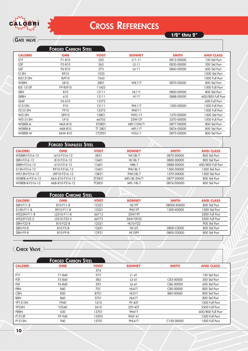
CROSS REFERENCES
FORGED CARBON STEEL
FORGED STAINLESS STEEL
CHECK VALVE
GATE VALVE
CALOBRI OMB VOGT BONNEY SMITH ANSI CLASSS1F F1-810 353 L11-11 0815-00000 150 Std PortS3F F3-810 363 L3-11 0830-00000 300 Std PortS6F F6-810 373 L6-11 0860-00000 600 Std PortS15N R910 1033 1500 Std PortRJS1515N RJ910 1043 1500 Full PortWS8N L810 2801 WIL11T 0870-00000 800 Std PortRJS 1515F F9-RJ910 11603 1500 Full PortS8N 810 12111 HL11T 0800-00000 800 Std PortS88N 610 13111 H11T 0888-00000 600/800 Full PortS66F F6-610 13373 600 Full PortS1515N 910 15111 9HL11T 1500-00000 1500 Full PortTS1515N T910 15373 9HLF11 1500 Full PortWS15N LR910 15801 9WL11T 1570-00000 1500 Std PortWS1515N L910 66703 25W12T 2570-00000 1500 Full PortWS8EB-A MLA-810 ST2801 MFL11SW/T 0877-00000 800 Std PortWS8EB-B MLB-810 TT 2801 MFL11T 0876-00000 800 Std PortWS8EB-W MLW-810 CT2901 VOLL11 0875-00000 800 Std Port
CALOBRI OMB VOGT BONNEY SMITH ANSI CLASSWS88N-F316-12 L610-F316-12 2831 WL18L-T 0870-D0000 800 Std PortS8N-F316-12 810-F316-12 12401 HL18L-T 0800-D0000 800 Std PortS88N-F316-12 610-F316-12 13401 HI8L-T 0888-D0000 600/800 Full PortS15N-F316-12 R910-F316L-12 15401 9HL18L-T 1500-D0000 1500 Std PortWS15N-F316-12 LR910-F316-12 15831 9WL18L-T 1570-D0000 1500 Std PortWS8EB-A-F316-12 MLA-810-F316-12 ST2831 MFL18L-SW/T 0877-D0000 800 Std PortWS8EB-B-F316-12 MLB-810-F316-12 TT2831 MFL-18L-T 0876/D0000 800 Std Port
FORGED CHROME STEELCALOBRI OMB VOGT BONNEY SMITH ANSI CLASSS8N-F11-8 810-F11-8 12321 HL19T 08000-K0000 800 Std PortS15N-F11-8 R910-F11-8 15321 9HL19T 1500-K0000 1500 Std PortWS25N-F11-8 L2510-F11-8 66713 25W19T 2500 Full PortWS25T-F22-5 L2510-F22-5 66773 26W10F22 2500 Full PortS8N-F22-8 810-F22-8 12521 HL10-F22 900 Std PortS8N-F5-8 810-F5-8 12421 HL16T 0800-C0000 800 Std PortS8N-F9-8 810-F9-8 12921 HL10F9 0800-G0000 800 Std Port
CALOBRI OMB VOGT BONNEY SMITH ANSI CLASS574
P1F F1-840 573 L1-41 150 Std PortP3F F3-840 583 L3-41 C83-00000 300 Std PortP6F F6-840 593 L6-41 C86-00000 600 Std PortP8N 840 701 HL41T C80-00000 800 Std PortC8N 850 B701 HL51T B80-00000 800 Std PortB8N 860 S701 HL61T 800 Std PortYP1515N Y940 1610 9Y-42T 1500 Full PortYP25N Y2540 2610 25Y-42T 2500 Full PortP88N 630 13701 9H41T 600/800 Full PortP1515F F9-940 15593 9HLF-41 1500 Full PortP1515N 940 15701 9HL41T C150-00000 1500 Full Port
FORGED CARBON STEEL
1/2” thru 2”
10

CROSS REFERENCES
API TRIM DESIGNTIONS AND OTHER PRODUCTS ARE AVAILABLE FROM CALOBRI
GLOBE VALVE
FORGED CARBON STEELCALOBRI OMB VOGT BONNEY SMITH ANSI CLASSD1F F1-830 473 L1-31 150 Std PortD3F F3-830 483 L3-31 G83-00000 300 Std PortD6F F6-830 493 L6-31 G86-00000 600 Std PortYD88N LY630 810 Y-32T 600/800 Full PortYD1515N Y930 1510 9Y-32T 1500 Full PortYD25N Y2530 2510 25Y-32T 2500 Full PortWD8N L830 2821 WL31T G87-00000 800 Std PortD8N 830 12141 HL31T 800 Std PortD88N 630 13141 H31T 600/800 Full PortD15N R930 15141 9HL31T G150-00000 1500 Full PortRJS1515F F9-RJ930 15493 9HLF31 1500 Full PortWD15N LR930 15821 9WL31T G157-00000 1500 Std PortWD25N L2530 66723 25W32T 2500 Full Port
FORGED STAINLESS STEEL
CALOBRI OMB VOGT BONNEY SMITH ANSI CLASSD8N-F316-12 830-F316-12 12501 HL38L-T G80-D0000 800 Std PortD15N-F316-12 R930-F316-12 15501 9HL38L-T G150-D0000 1500 Std Port
FORGED CHROME STEEL
CALOBRI OMB VOGT BONNEY SMITH ANSI CLASSYD15N-F11-5 LY930-F11-5 1511 9Y-39T 1500 Full PortYD15N-F22-5 LY930-F22-5 1522 9Y-30T-F22 1500 Full PortYD25N-F11-5 Y2530-F11-5 2511 25Y-39T 2500 Full PortYD25N-F22-5 Y2530-F22-5 2522 25Y-30T-F22 2500 Full PortD8T-F11-5 830-SW-F11-5 12351 HL39T G80-K0000 800 Std PortD8T-F22-5 830-SW-F22-5 12551 HL30T-F22 800 Std PortWD8-F11-5 L830-F11-5 66733 25 W-39T 800 Std PortWD8-F22-5 L830-F22-5 66793 25W30T-F22 800 Std Port
FORGED STAINLESS STEELCALOBRI OMB VOGT BONNEY SMITH ANSI CLASSP8N-F316-12 840 718 HL48T C80-00000 800 Std PortC8N-F316-12 850 B718 HL58T B80-00000 800 Std PortB8N-F316-12 860 S718 HL68T 800 Std Port
FORGED CHROME STEELCALOBRI OMB VOGT BONNEY SMITH ANSI CLASSYP1515N-F11-8 Y940-F11-8 1611 9Y-49T 1500 Full PortYP1515N-F22-8 Y940-F22-8 1622 9Y-40T-F22 1500 Full PortYP25N-F11-5 Y2540-F11-5 2611 25Y-49T 2500 Full PortYP25N-F22-5 Y2540-F22-5 2622 25Y-40T-F22 2500 Full Port
1/2” thru 2”
11
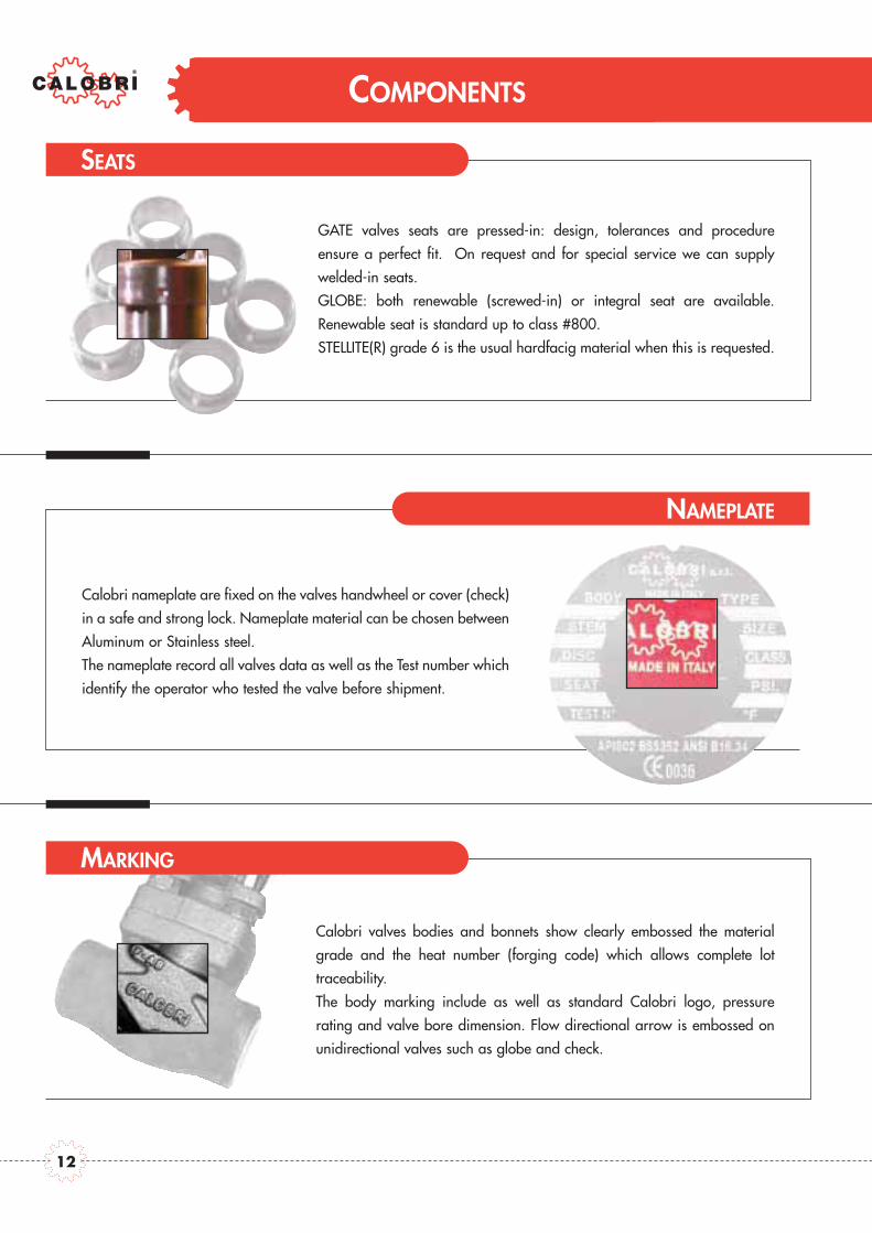
COMPONENTS
Calobri nameplate are fixed on the valves handwheel or cover (check)
in a safe and strong lock. Nameplate material can be chosen between
Aluminum or Stainless steel.
The nameplate record all valves data as well as the Test number which
identify the operator who tested the valve before shipment.
SEATS
Calobri valves bodies and bonnets show clearly embossed the material
grade and the heat number (forging code) which allows complete lot
traceability.
The body marking include as well as standard Calobri logo, pressure
rating and valve bore dimension. Flow directional arrow is embossed on
unidirectional valves such as globe and check.
MARKING
GATE valves seats are pressed-in: design, tolerances and procedure
ensure a perfect fit. On request and for special service we can supply
welded-in seats.
GLOBE: both renewable (screwed-in) or integral seat are available.
Renewable seat is standard up to class #800.
STELLITE(R) grade 6 is the usual hardfacig material when this is requested.
NAMEPLATE
12

COMPONENTS
GASKET
PACKING
It takes 50 years to excel in fugitive emission control! Calobri
packing have undergone a continuous development to achieve
the best results with the lowest cost impact. Our packings offer
now include traditional square section graphite packing and
cup-and-cone designs.
STEM AND WEDGE
We have been working to improve these two components
in two areas: perfect exterior surfaces of stem to
guarantee smooth operation and lowest emissions and
tight tolerances in the connection to meet stringent “Pull
Test” resistant design request.
Calobri gaskets and contact area have been designed to
meet the most stringent request: Zero Emission. Calobri is
now able to certify 0PPM emission from the gasket area
thanks to special anti-extrusion design, closer tolerances
and controlled material density.
13

Application Notes
BODY AND BONNET MATERIALS
CALOBRI valves are manufactured in a wide range of materials, supplied by the best available steel mills, forged bywell known forgery with outstanding equipment and experience. All the material can be certified in the chemical composition and the mechanical characteristic.
Note: these charts are for reference only. CALOBRI recommends customer engineers to analize service requirements and specify the materials they consider optimium.CALOBRI cannot be held liable for any damage occured due to the use of the tables.
Carbon Steel CS C-Mn-Fe K03504 A105N A216-WCB C22.8 DIN 17243 1.0460
Low TemperatureA352-LCA
Carbon SteelLTCS C-Mn-Fe K03011 A350-LF2 A352-LCB TSTE 355 DIN 18103 1.0566
A352-LCC
Low TemperatureAlloy Steel
Nickel Steel 3.1/2Ni K32025 A350-LF3 A352-LC3 10Ni14 1.5637
Moly Steel C-1/2Mo K12822 A182-F1 A217-WC1 15MO3 1.5415
1.1/4Cr-1/2Mo K11572 A182-F11 cl2 A217-WC6 13CRMO44 1.7335
2.1/4Cr-1Mo K21590 A182-F22 cl3 A217-WC9 10CRMO910 1.7380
5Cr-1/2Mo K41545 A182-F5 A217-C5 12CRMO195 1.7362
9Cr-1Mo K90941 A182-F9 A217-C12 X 12 CrMo 9 1 1.7386
9Cr-1Mo-V A182-F91 A217-C12A X 10 CrMoVNb 9 1 1.4903
304 : 18Cr-8Ni S30400 A182-F304 A351-CF8 DIN X5CrNi 18 9 1.4301
304L : 18Cr-8Ni S30403 A182-F304L A351-CF3 X 2 CrNi 19 11 1.4306
304H : S30409 A182-F304H n/a n/a
316 : 16Cr-12Ni-2Mo S31600 A182-F316 A351-CF8M DIN X5CrNiMo 18 10 1.4401
316L : 16Cr-12Ni-2Mo S31603 A182-F316L A351-CF3M X 5 CrNiMo 17 12 2 1.4404
316H : S31609 A182-F316H n/a n/a
316Ti: S31635 A182-F316Ti X 6 CrNiMoTi 17 12 2 1.4571
321: 18Cr-10Ni-Ti S32100 A182-F321 X 6 CrNiTi 18 10 1.4541
321H S32109 A182-F321H n/a n/a
347: 18Cr-10Ni-Cb(Nb) S34700 A182-F347 A351-CF8C DIN 8556 1.4550
347H S34709 A182-F347H n/a n/a
317L S31703 A182-F317L A351-CG3M X2CrNiMo18-16-4 1.4438
Alloy 20 28Ni-19Cr-Cu-Mo N08020 A182-F20 A351-CN7M DIN 1.4500 2.4660
Duplex 2205 22Cr-5Ni-3Mo-NS31803
A182-F51 A890-J92205X2CrNiMON22-5-3
1.4462S32205 DIN 10088-1 (95)
Super Duplex 2507 25Cr-7Ni-4Mo-N S32750 A182-F53A351-CD4MCu X2CrNiMoN25-7-4
1.4501A890 5A DIN 10088-1 (95)
Super Austenitic20Cr-18Ni-6Mo S31254 A182-F44 A351-CK3MCuN
X1CrNiMoCuN20-18-7 1.45476Mo DIN 10088-1 (95)
Nickel-Iron AlloyIncoloy 800 33Ni-42Fe-21Cr N08800 B564-N08800 X10NiCrAlTi32-20 1.4876
Incoloy 825 42Ni-21.5Cr-3Mo-2.3Cu N08825 B564-N08825 A494-CU5MCuC DIN 17744 2.4858
Nickel Nickel 99/95Ni N02200 B160-N02200 (bar) A494-CZ-100 NW2200 1.7740
Nickel-CopperMonel 400 67Ni-30Cu N04400 B564-N04400 A494-M35-1 DIN 17730 2.4360
Monel 500 N05500 B564-N05500 2.4375
Nickel-Alloy 904L N08904 904L n/a Z2 NCDU 25-20 1.4539
Inconel 600 72Ni-15Cr-8Fe N06600 B564-N06600 A494-CY40 DIN 17742 2.4816
Nickel Superalloys Inconel 625 60Ni-22Cr-9Mo-3.5Cb N06625 B564-N06625* A494-CW-6MC 2.4856
Hastelloy C-276 54Ni-15Cr-16Mo N10276 B564-N10276* A494-CW-2M NiMo 16 Cr 15 W 2.4819
Titanium Titanium 98Ti R50400 B381-Gr2 B367-C2 Ti 2 3.7035
MaterialGroup
Common Name Nominal Type UNS Forging Spec. Casting Spec.
Equivalent DIN DIN W. No
General non-corrosive service from -20F(-29C) to 800F(427C)
General non-corrosive service from -50F(-46C) to 650F(340C), LF2 to 800F(427C).
-150F(-101C) to 650F(340C)
Up to 875F (468C)
Up to 1100F (593C)
Up to 1100F(593C), HP steam
High temp refinery service
High temp erosive refinery service
High pressure steam
0.04% min. carbon for temp.>1000F(538C)
Up to 800F(427C)
0.04% min. carbon for temp.>1000F(538C)
Up to 800F(427C)
0.04% min. carbon (grade F321H) and heat treatat 2000F(1100C) for service temps.>1000F(538C)
0.04% min. carbon (grade F347H) and heat treatat 2000F(1100C) for service temps.>1000F(538C)
service to 600F(316C)
service to 600F(316C) -The original S31803 UNSdesignation has been supplemented by S32205which has higher minimum N, Cr, and Mo.
service to 600F(316C)
service to 600F(316C)
service to 1000F(538C)
service to 600F(316C) for N02200,1200F(648C) for N02201
*Difficult to forge in close dye
*Difficult to forge in close dye
Low
Alloy
Stee
lSta
inles
s Stee
l
Alloy
Stee
lCh
rome
Moly
Auste
nitic
S.Stee
l30
0 se
ries S
.Stee
l
MATERIALS
BODY AND BONNET MATERIALS
14

MATERIALS
TRIM STANDARD MATERIALS
The following tables suggest standard combination of body and bonnet materials and trim (stem, disc or wedge, seat)composition. Different combinations are available uppon request.
DESIGN AND MANUFACTURING STANDARDS
API 598 - Valve inspection and Test
ASME B 16.5 - Steel Pipe Flanges and Fittings
ASME B 16.10 - Face-to-Face and End-to-End Dimensionof Ferrous Valves
ASME B 16.11 - Forged Steel Fittings, Socket-Weldingand Threaded
ASME B 16.34 - Steel Valves, Flanged and Buttwelded Ends
MSS SP 25 - Standard Marking System for Valves,Fittings, Flanges and Unions
BS 5352 - Specific for Cast and Forged Steel WedgeGate, Globe, Check and Plug Valves,Screwed and Socket-Weld
BS 6755 - Testing of valves
NACE Standard - Material Requirement - Sulfide StressCracking Resistant
MR 01.75 - Metallic Material for Oil Field Equipment
DIN 3202 - End to End dimensions offerrous valves
CALOBRI STANDARD TRIM DEFINITIONS
CALOBRI TRIM MATERIAL
API Trim No Nonimal Trim CALOBRI descr. Stem Disc/Wedge Seat
1 F6 F6 410 F6 410
2 304 304 304 304 304
5 Hardfaced F6HF 410 F6 + St Gr6 410 + St Gr6
8 F6 and Hardfaced F6HFS 410 F6 410 + St Gr6
9 Monel Monel Monel Monel Monel
10 316 316 316 316 316
11 Monel and Hardfaced MonelHFS Monel Monel Monel
12 316 and Hardfaced 316HFS 316 316 316 + St. Gr6
13 Alloy 20 Alloy 20 Alloy 20 Alloy 20 Alloy 20
14 Alloy 20 and Hardfaced Alloy 20HFS Alloy 20 Alloy 20 Alloy 20
15 Hardfaced (304) 304-HF 304 304 + St Gr6 304 + St Gr6
16 Hardfaced (316) 316-HF 316 HF 316 + St Gr6 316 + St Gr6
17 Hardfaced (347) 347-HF 347 HF 347 + St Gr6 347 + St Gr6
18 Hardfaced (Alloy 20) Alloy 20-HF Alloy 20 HF Alloy 20 + St Gr6 Alloy 20 + St Gr6
n/a Alloy 625 Alloy 625 Alloy 625 Alloy 625 Alloy 625
CALOBRI UNS TYPE Grade (forged) ASTM wrought DIN DIN W NO.
F6 UNS S41000 13Cr ASTM A182 F6a A276-410 DIN X12Cr13 1,4006
304 UNS S30400 18-8 Cr-Ni ASTM A182 F304 A276-304 DIN X5CrNi 18 10 1,4301
316 UNS S31600 18-8 Cr-Ni (18-10-2) ASTM A182 F316 A276-316 DIN X5CrNiMo 18 10 1,4401
321 UNS S32100 18 Cr-10 Ni-Ti ASTM A182 F321 A276-321 DIN X6CrNiTi 18 10 1.4541
347 UNS S34700 18 Cr-10 Ni-Cb ASTM A182 F347 A276-347 DIN X6CrNiNb18 10 1.4550
MONEL(R) UNS N04400 67Ni-30Cu ASTM B564-N04400 B164-N04400 DIN 17743 2.4360
ALLOY 20 UNS N08020 28Ni-19Cr-Cu-Mo ASTM A182-F20 ASTM B473 DIN 14500 2.4660
ALLOY 625 UNS N06625 60Ni-22Cr-9Mo-3.5Cb ASTM B564-N06625 ASTM B564-N06625 DIN 17361 2.4865
C276 UNS N10276 54Ni-15Cr-16Mo ASTM B564-N10276 ASTM B574-N10276 DIN NiMo 16 Cr 15 W 2,4819
St. Gr6 UNS R30006 Co Cr-A AMS 5894 Stellite(R) Gr6
TRIM STANDARD MATERIALS
15

VALVE DATA FORGED STEEL
GATE VALVES

GATE VALVES
Gate valves are bi-directional valves ideally suited for on-off duties. CALOBRI produces various types both with parallelface gates or with wedge gates. These valves have a very low resistance to flow, which in the case of parallel gate valvesapproaches that of a straight pipe. They are used for duties with high pressure fluids due to the fact that upstreampressure helps the sealing between gate and seat.CALOBRI takes great care to study finish of seating surfaces to guarantee their minimum wear under high pressures.Gate valves are supplied in various models to cover the most different and delicate services.
Note Bellows Seal Valves please see special sectionCryogenic Service please see special sectionPressure Seal Valves please see special section
JIS Valve Standards Available on requestDIN Valve Standards Available on request
Inside Screw Valve Standards Available on request
CLASS CONNECTION PORT STANDARD Screw & Yoke ENDS SERVICE CALOBRI800 Bolted bonnet Reduced API602-BS5352 Outside Threaded and Socket Weld Ends - S8800 Bolted bonnet Full API602-BS5352 Outside Threaded and Socket Weld Ends - S88800 Welded Bonnet Reduced API602-BS5352 Outside Threaded and Socket Weld Ends - W-S8800 Welded Bonnet Full API602-BS5352 Outside Threaded and Socket Weld Ends - W-S88
1500 Bolted bonnet Reduced API602-BS5352 Outside Threaded and Socket Weld Ends - S151500 Bolted bonnet Full API602-BS5352 Outside Threaded and Socket Weld Ends - S15151500 Welded Bonnet Reduced API602-BS5352 Outside Threaded and Socket Weld Ends - W-S151500 Welded Bonnet Full API602-BS5352 Outside Threaded and Socket Weld Ends - WS15151500 Ring Joint BB Full BS5352 Outside Threaded and Socket Weld Ends - RJ-S15152500 Ring Joint BB Full ANSI B16.34 Outside Threaded and Socket Weld Ends - RJ-S252500 Welded Bonnet Full ANSI B16.34 Outside Threaded and Socket Weld Ends - W-S25800 Welded Bonnet Reduced API602 Outside Extended Body - Male Threaded - W-S8EB-A800 Welded Bonnet Reduced API602 Outside Extended Body - Male Socket - W-S8EB-B800 Welded Bonnet Reduced API602 Outside Extended Body - BW - W-S8EB-C800 Bolted bonnet Reduced API602 Outside Extended Body - Male Threaded - S8EB-A800 Bolted bonnet Reduced API602 Outside Extended Body - Male Socket - S8EB-B800 Bolted bonnet Reduced API602 Outside Extended Body - BW - S8EB-C800 Welded Bonnet Reduced API602 Outside Extended Body - Reinforced - BW - W-S8EB-D800 Welded Bonnet Reduced API602 Outside Extended Body - Reinforced - LIP W-S8EB-W800 Bolted bonnet Reduced API602 Outside Extended Body - Reinforced - BW - S8EB-D800 Bolted bonnet Reduced API602 Outside Extended Body - Reinforced - LIP S8EB-W
1500 Welded Bonnet Reduced API602 Outside Extended Body - Male Threaded - W-S15EB-A1500 Welded Bonnet Reduced API602 Outside Extended Body - Male Socket - W-S15EB-B1500 Welded Bonnet Reduced API602 Outside Extended Body - BW - W-S15EB-C1500 Bolted bonnet Reduced API602 Outside Extended Body - Male Threaded - S15EB-A1500 Bolted bonnet Reduced API602 Outside Extended Body - Male Socket - S15EB-B1500 Bolted bonnet Reduced API602 Outside Extended Body - BW - S15EB-C1500 Welded Bonnet Reduced API602 Outside Extended Body - Reinforced - BW - W-S15EB-D1500 Welded Bonnet Reduced API602 Outside Extended Body - Reinforced - LIP W-S15EB-W1500 Bolted bonnet Reduced API602 Outside Extended Body - Reinforced - BW - S15EB-D1500 Bolted bonnet Reduced API602 Outside Extended Body - Reinforced - LIP S15EB-W800 Bolted bonnet Reduced API602-BS5352 Outside Threaded and Socket Weld Ends Sour Service SS-S8800 Welded Bonnet Reduced API602-BS5352 Outside Threaded and Socket Weld Ends Alkylation AS-WS8800 Welded Bonnet Reduced API602-BS5352 Outside Threaded and Socket Weld Ends Vacuum SV-WS8800 Bolted bonnet Reduced API602-BS5352 Outside Threaded and Socket Weld Ends Chlorine CS-S8
18

GATE VALVES
Class 800 and 1500 Bolted Bonnet - Full and Reduced bore

GATE VALVES
Design & Construction:API 602 - BS 5352Testing according to API 598 - BS 6755Marking MSS SP25
Outside Screw and Yoke (OS&Y)Self aligning packing gland.Spiral-wound gasket retained type.Integral backseatSocket weld Ends to ANSI B16.11Screwed Ends (NPT) to ANSIB1.20.1Butt Welding Ends to ANSI B.16.25Ratings:- carbon steel class 800 1975 psig @ 100° F
138 bar + 38° C- carbon steel class 1500 3705 psig @ 100° F
255 bar + 38° C
CLASS 1500
CLASS 800
SIZE inch 1/4 3/8 1/2 3/4 1 1.1/4 1.1/2 2mm 6 10 15 20 25 32 40 50
A inch 3.14 3.14 3.54 4.33 5.00 5.00 5.00 8.26mm 80 80 90 110 127 127 127 210
B Open inch 5.86 5.86 6.41 7.00 8.26 9.56 10.3 14.3mm 148 148 163 178 210 243 262 365
C inch 0.31 0.38 0.55 0.70 0.94 1.18 1.45 1.89mm 8 9.6 14 18 24 30 37 48
Handwheel inch 3.14 3.14 3.14 4.33 4.33 5.11 5.11 7.08mm 80 80 80 110 110 130 130 180
WEIGHT lb 3.5 3.5 4.8 7.7 11 14.3 19.8 47.3kg 1.6 1.6 2.2 3.5 5 6.5 9 21.5
FIGUREPACKING T2 T2 T2 T4 T5 T6 T6 T8GASKET 40x30 40x30 40x30 48x38 54x44 66x54 74x60 95x78
FULL BORE
SIZE inch 1/2 3/4 1 1.1/4 1.1/2 2mm 15 20 25 32 40 50
A inch 3.14 3.54 4.33 5.00 5.00 5.00mm 80 90 110 127 127 127
B Open inch 5.86 6.41 7.00 8.26 9.56 10.3mm 148 163 178 210 243 262
C inch 0.38 0.55 0.70 0.94 1.18 1.45mm 9.6 14 18 24 30 37
Handwheel inch 3.14 3.14 4.33 4.33 5.11 5.11mm 80 80 110 110 130 130
WEIGHT lb 3.5 4.8 7.7 11 14.3 19.8kg 1.6 2.2 3.5 5 6.5 9
FIGUREPACKING T2 T2 T4 T5 T6 T6GASKET 40x30 40x30 48x38 54x44 66x54 74x60
REDUCED BORE
SIZE inch 1/4 3/8 1/2 3/4 1 1.1/4 1.1/2 2mm 6 10 15 20 25 32 40 50
A inch 3.54 3.54 4.33 5.00 5.00 5.00 8.26 8.26mm 90 90 110 127 127 127 210 210
B Open inch 5.70 6.29 6.89 8.26 9.45 10.2 13.9 14.1mm 145 160 175 210 240 260 355 360
C inch 0.31 0.38 0.55 0.70 0.94 1.18 1.45 1.57mm 8 9.6 14 18 24 30 37 40
Handwheel inch 3.14 3.14 4.33 4.33 5.11 5.11 7.08 7.08mm 80 80 110 110 130 130 180 180
WEIGHT lb 4.8 4.8 8.3 12.1 14.9 20.9 49.5 48.4kg 2.2 2.2 3.8 5.5 6.8 9.5 22.5 22
FIGUREPACKING T4 T4 T5 T25 T6 T27 T8 T918GASKET 40x30 40x30 40x30 48x38 54x44 66x54 74x60 74x60
FULL BORE
SIZE inch 1/2 3/4 1 1.1/4 1.1/2 2mm 15 20 25 32 40 50
A inch 3.54 4.33 5.00 5.00 5.00 8.26mm 90 110 127 127 127 210
B Open inch 6.29 6.89 8.26 9.45 10.2 13.9mm 160 175 210 240 260 355
C inch 0.38 0.55 0.70 0.94 1.18 1.45mm 9.6 14 18 24 30 37
Handwheel inch 3.14 4.33 4.33 5.11 5.11 7.08mm 80 110 110 130 130 180
WEIGHT lb 4.8 8.3 12.1 14.9 20.9 49.5kg 2.2 3.8 5.5 6.8 9.5 22.5
FIGUREPACKING T4 T5 T25 T6 T27 T8GASKET 40x30 40x30 48x38 54x44 66x54 74x60
REDUCED BORE
S88 S8
S1515 S15
20
GATE VALVES
Class 1500 and 2500 Bolted Bonnet - Full Bore

CLASS 2500
CLASS 1500
GATE VALVES
Design & Construction:BS 5352ASME B16.34Testing according to API 598 - BS 6755Marking MSS SP25
Outside Screw and Yoke (OS&Y)Self aligning packing gland in two partsIntegral backseatOval ring joint gasket
Socket weld Ends to ANSI B16.11Screwed Ends (NPT) to ANSI B1.20.1Butt Welding Ends to ANSI B.16.25Ring - Joint Gasket to ASME B16.20 - API 6A
Ratings standard class:- carbon steel class 1500 3705 psig @ 100° F
255 bar + 38° C- carbon steel class 2500 6170 psig @ 100° F
425 bar + 38° C
SIZE inch 1/4 3/8 1/2 3/4 1 1.1/4 1.1/2 2mm 6 10 15 20 25 32 40 50
A inch - - 4.33 5.90 5.90 - 8.26 9.25mm - - 110 150 150 - 210 235
B Open inch - - 8.93 11.8 12 - 15.7 17.6mm - - 227 300 307 - 400 448
C inch - - 0.55 0.70 0.94 - 1.45 1.89mm - - 14 18 24 - 37 48
Handwheel inch - - 4.33 5.11 5.11 - 7.08 9.84mm - - 110 130 130 - 180 250
WEIGHT lb - - 11.0 22.0 25.3 - 48.4 81.5kg - - 5 10 11.5 - 22 37
FIGUREPACKING - - T5 T6 T6 - T8 T918GASKET - - RJ-13 RJ-16 RJ-17 - RJ-21 RJ-24
FULL BORE
SIZE inch 1/4 3/8 1/2 3/4 1 1.1/4 1.1/2 2mm 6 10 15 20 25 32 40 50
A inch - - 5.90 5.90 8.26 - 9.25 9.25mm - - 150 150 210 - 235 235
B Open inch - - 11.5 11.8 15.3 - 17.1 17.1mm - - 293 300 390 - 435 435
C inch - - 0.55 0.70 0.94 - 1.45 1.45mm - - 14 18 24 - 37 37
Handwheel inch - - 5.11 5.11 9.84 - 11.8 11.8mm - - 130 130 250 - 300 300
WEIGHT lb - - 22.0 22.7 49.3 - 83.7 83.7kg - - 10 10.3 22.4 - 38 38
FIGUREPACKING - - T25X T6X T8X - T2528X T2528XGASKET - - RJ-13 RJ-16 RJ-17 - RJ-21 RJ-21
FULL BORE
RJS1515
RJS25
22

21
Class 800 and 1500 Welded Bonnet - Full and Reduced Bore
GATE VALVES

CLASS 1500
CLASS 800
Design & Construction:API 602 - BS 5352ASME B16.34Testing according to API 598 - BS 6755Marking MSS SP25
Outside Screw and Yoke (OS&Y)Self aligning packing gland in two partsIntegral backseatFull Penetration weldScrewed & Seal weld on request
Socket weld Ends to ANSI B16.11Screwed Ends (NPT) to ANSI B1.20.1Butt Welding Ends to ANSI B.16.25
Ratings standard class:- carbon steel class 800 1475 psig @ 100°F
138 bar +38°C- carbon steel class 1500 3705 psig @ 100° F
255 bar + 38° C
GATE VALVES
SIZE inch 1/4 3/8 1/2 3/4 1 1.1/4 1.1/2 2mm 6 10 15 20 25 32 40 50
A inch 3.14 3.14 3.54 4.33 5.00 5.00 5.00 8.26mm 80 80 90 110 127 127 127 210
B Open inch 3.14 5.86 6.41 7.00 8.26 9.56 10.3 14.3mm 148 148 163 178 210 243 262 365
C inch 0.31 0.38 0.55 0.70 0.94 1.18 1.45 1.89mm 8 9.6 14 18 24 30 37 48
Handwheel inch 3.14 3.14 3.14 4.33 4.33 5.11 5.11 7.08mm 80 80 80 110 110 130 130 180
WEIGHT lb 3.5 3.5 4.8 7.7 11 13.8 17.6 37.4kg 1.6 1.6 2.2 3.5 5 6.3 8 17
FIGUREPACKING T2 T2 T2 T4 T5 T6 T6 T8
FULL BORE
SIZE inch 1/2 3/4 1 1.1/4 1.1/2 2mm 15 20 25 32 40 50
A inch 3.14 3.54 4.33 5.00 5.00 5.00mm 80 90 110 127 127 127
B Open inch 5.86 6.41 7.00 8.26 9.56 10.3mm 148 163 178 210 243 262
C inch 0.38 0.55 0.70 0.94 1.18 1.45mm 9.6 14 18 24 30 37
Handwheel inch 3.14 3.14 4.33 4.33 5.11 5.11mm 80 80 110 110 130 130
WEIGHT lb 3.5 4.8 7.7 11 13.8 17.6kg 1.6 2.2 3.5 5 6.3 8
FIGUREPACKING T2 T2 T4 T5 T6 T6
REDUCED BORE
SIZE inch 1/4 3/8 1/2 3/4 1 1.1/4 1.1/2 2mm 6 10 15 20 25 32 40 50
A inch 3.54 3.54 4.33 5.00 5.00 5.00 8.26 8.26mm 90 90 110 127 127 127 210 210
B Open inch 5.70 6.29 6.89 8.26 9.45 10.2 13.9 14.1mm 145 160 175 210 240 260 355 360
C inch 0.31 0.38 0.55 0.70 0.94 1.18 1.45 1.57mm 8 9.6 14 18 24 30 37 40
Handwheel inch 3.14 3.14 4.33 4.33 5.11 5.11 7.08 7.08mm 80 80 110 110 130 130 180 180
WEIGHT lb 4.8 4.8 8.3 12.1 15 19.8 39.6 38.5kg 2.2 2.2 3.8 5.5 6.8 9 18.0 17.5
FIGUREPACKING T4 T4 T5 T25 T6 T27 T8 T918
FULL BORE
SIZE inch 1/2 3/4 1 1.1/4 1.1/2 2mm 15 20 25 32 40 50
A inch 3.54 4.33 5.00 5.00 5.00 8.26mm 90 110 127 127 127 210
B Open inch 6.29 6.89 8.26 9.45 10.2 13.9mm 160 175 210 240 260 355
C inch 0.38 0.55 0.70 0.94 1.18 1.45mm 9.6 14 18 24 30 37
Handwheel inch 3.14 4.33 4.33 5.11 5.11 7.08mm 80 110 110 130 130 180
WEIGHT lb 4.8 8.3 12.1 15 19.8 39.6kg 2.2 3.8 5.5 6.8 9 18.0
FIGUREPACKING T4 T5 T25 T6 T27 T8
REDUCED BORE
WS88
WS1515
WS8
WS15
24

GATE VALVES
Class 2500 Welded Bonnet - Full Bore

CLASS 2500
Design & Construction:BS 5352ASME B16.34Testing according to API 598 - BS 6755Marking MSS SP25
Outside Screw and Yoke (OS&Y)Self aligning packing gland in two partsIntegral backseatFull penetration weldScrewed & Seal welde on requestSocket weld Ends to ANSI B16.11Screwed Ends (NPT) to ANSI B1.20.1Butt Welding Ends to ANSI B.16.25
Ratings standard class:- carbon steel class 2500 6170 psig @ 100° F
425 bar + 38° C
GATE VALVES
SIZE inch 1/4 3/8 1/2 3/4 1 1.1/4 1.1/2 2mm 6 10 15 20 25 32 40 5
A inch - - 5.00 5.00 5.00 - 9.25 9.25mm - - 127 127 127 - 235 235
B Open inch - - 8.42 9.40 9.96 - 16.7 16.9mm - - 214 239 253 - 425 430
C inch - - 0.55 0.70 0.94 - 1.45 1.45mm - - 14 18 24 - 37 37
Handwheel inch - - 5.11 5.11 5.11 - 11.8 11.8mm - - 130 130 130 - 300 300
WEIGHT lb - - 12.7 15.4 22.0 - 57.3 56.2kg - - 5.8 7 10 - 26 25.5
FIGUREPACKING - - T6X T6X T8X - T2528X T2528X
FULL BORE
WS25
26

GATE VALVES
Class 800 and 1500 Bolted Bonnet - Welded Bonnet
Extended Body

Design construction:API 602Testing according to API 598 - BS 6755Marking MSS SP25
Outside Screw and Yoke (OS&Y)Self aligning packing gland in two partsSpiral-wound gasket retained type Integral backseatSocket weld Ends to ANSI B16.11Screwed Ends (NPT) to ANSIB1.20.1Butt Welding Ends to ANSI B.16.25
Ratings:- carbon steel class 800 1975 psig @ 100° F
138 bar + 38° C- carbon steel class 1500 3705 psig @ 100° F
255 bar + 38° C
CLASS 800 CLASS 1500
CLASS 800 CLASS 1500BOLTED BONNET
WELDED BONNET
EXTENDED BODY
SIZE inch 1/2 3/4 1 1.1/2 2mm 15 20 25 40 50
A inch 5.82 6.02 7.16 8.50 10.4mm 148 153 182 216 264
A1 inch 4.25 4.25 5.00 6.00 7.87mm 108 108 127 152 200
B Open inch 5.82 6.41 7.00 9.56 10.3mm 148 163 178 243 262
C inch 0.38 0.55 0.70 1.18 1.45mm 9.6 14 18 30 37
Handwheel inch 3.14 3.14 4.33 5.11 5.11mm 80 80 110 130 130
WEIGHT lb 4.6 6.2 9.7 18.3 26.4kg 2.1 2.8 4.4 8.3 12
FIGUREPACKING T2 T4 T5 T6 T8GASKET 40x30 48x38 54x44 74x60 95x78
SIZE inch 1/2 3/4 1 1.1/2 2mm 15 20 25 40 50
A inch 5.82 6.02 7.16 8.50 10.4mm 148 153 182 216 264
A1 inch 4.25 4.25 5.00 6.00 7.87mm 108 108 127 152 200
B Open inch 5.82 6.41 7.00 9.56 10.3mm 148 163 178 243 262
C inch 0.38 0.55 0.70 1.18 1.45mm 9.6 14 18 30 37
Handwheel inch 3.14 3.14 4.33 5.11 5.11mm 80 80 110 130 130
WEIGHT lb 4.6 6.2 9.7 17.8 23.2kg 2.1 2.8 4.4 8.1 10.5
FIGUREPACKING T2 T4 T5 T6 T8
SIZE inch 1/2 3/4 1 1.1/2 2mm 15 20 25 40 5
A inch 6.02 7.16 8.50 10.4 10.4mm 153 182 216 264 264
A1 inch 4.25 5.00 6.00 7.87 7.44mm 108 127 152 200 189
B Open inch 6.41 7.00 8.26 10.3 13.9mm 163 178 210 262 355
C inch 0.38 0.55 0.70 1.18 1.45mm 9.6 14 18 30 37
Handwheel inch 3.14 4.33 4.33 5.11 7.08mm 80 110 110 130 180
WEIGHT lb 6.8 10.6 16.5 25.3 46.5kg 3.1 4.8 7.5 11.5 21.1
FIGUREPACKING T5 T25 T6 T8 T918
SIZE inch 1/2 3/4 1 1.1/2 2mm 15 20 25 40 50
A inch 6.02 7.16 8.50 10.4 10.4mm 153 182 216 264 264
A1 inch 4.25 5.00 6.00 7.87 7.44mm 108 127 152 200 189
B Open inch 6.41 7.00 8.26 10.3 13.9mm 163 178 210 262 355
C inch 0.38 0.55 0.70 1.18 1.45mm 9.6 14 18 30 37
Handwheel inch 3.14 4.33 4.33 5.11 7.08mm 80 110 110 130 180
WEIGHT lb 6.8 10.6 16.5 26.4 48.7kg 3.1 4.8 7.5 12 22.1
FIGUREPACKING T5 T25 T6 T8 T918GASKET 40x30 48x38 54x44 74x60 74x60
S8EB
WS8EB
S15EB
WS15EB
28

Class 800 and 1500 Bolted Bonnet - Welded Bonnet
Reinforced Extended Body
GATE VALVES

REINFORCED EXTENDED BODY
Design construction:API 602Testing according to API 598 - BS 6755Marking MSS SP25
Outside Screw and Yoke (OS&Y)Self aligning packing glandSpiral-wound gasket retained type Integral backseatSocket weld Ends to ANSI B16.11Screwed Ends (NPT) to ANSIB1.20.1Butt Welding Ends to ANSI B.16.25
Ratings:- carbon steel class 800 1975 psig @ 100° F
138 bar + 38° C- carbon steel class 1500 3705 psig @ 100° F
255 bar + 38° C
CLASS 800 CLASS 1500
CLASS 800 CLASS 1500BOLTED BONNET
WELDED BONNET
SIZE inch 1/2 3/4 1 1.1/2 2mm 15 20 25 40 50
A inch 7.71 8.66 9.60 10.4 10.6mm 196 220 244 265 270
A1 inch 6.14 6.88 7.44 7.91 8.11mm 156 175 189 201 206
B Open inch 5.82 6.41 7.00 9.56 10.3mm 148 163 178 243 262
C inch 0.38 0.55 0.70 1.18 1.45mm 9.6 14 18 30 37
Handwheel inch 3.14 3.14 4.33 5.11 5.11mm 80 80 110 130 130
WEIGHT lb 6.6 7.0 11.0 20.9 27.5kg 3 3.2 5 9.5 12.5
FIGUREPACKING T2 T4 T5 T6 T8GASKET 40x30 48x38 54x44 74x60 95x78
SIZE inch 1/2 3/4 1 1.1/2 2mm 15 20 25 40 5
A inch 8.66 9.60 10.4 10.6 10.6mm 220 244 265 270 270
A1 inch 6.88 7.44 7.91 8.11 6.50mm 175 189 201 206 165
B Open inch 6.41 7.00 8.26 10.3 13.9mm 163 178 210 262 355
C inch 0.38 0.55 0.70 1.18 1.45mm 9.6 14 18 30 37
Handwheel inch 3.14 4.33 4.33 5.11 7.08mm 80 110 110 130 180
WEIGHT lb 7.7 11.9 17.8 29.7 53.0kg 3.5 5.4 8.1 13.5 24.1
FIGUREPACKING T2 T2 T4 T6 T6GASKET 40x30 40x30 48x38 66x54 74x60
SIZE inch 1/2 3/4 1 1.1/2 2mm 15 20 25 40 50
A inch 7.71 8.66 9.60 10.4 10.6mm 196 220 244 265 270
A1 inch 6.14 6.88 7.44 7.91 8.11mm 156 175 189 201 206
B Open inch 5.82 6.41 7.00 9.56 10.3mm 148 163 178 243 262
C inch 0.38 0.55 0.70 1.18 1.45mm 9.6 14 18 30 37
Handwheel inch 3.14 3.14 4.33 5.11 5.11mm 80 80 110 130 130
WEIGHT lb 6.6 7.0 11.0 20.5 27.5kg 3 3.2 5 9.3 12.5
FIGUREPACKING T5 T25 T6 T8 T918
SIZE 1/2 4/3 1 1.1/2 2
H inch 0.70 0.91 1.10 1.73 1.97mm 18 23 28 44 50
I inch 0.80 1.00 1.20 1.85 2.08mm 20.5 25.5 30.5 47 53
G inch 0.15 0.17 0.19 0.25 0.31mm 4 4.5 5 7 8
Min. 1 1.1/2 2 3 4
Reinforced - Lip -Class 800 & 1500
SIZE inch 1/2 3/4 1 1.1/2 2mm 15 20 25 40 5
A inch 8.66 9.60 10.4 10.6 10.6mm 220 244 265 270 270
A1 inch 6.88 7.44 7.91 8.11 6.50mm 175 189 201 206 165
B Open inch 6.41 7.00 8.26 10.3 13.9mm 163 178 210 262 355
C inch 0.38 0.55 0.70 1.18 1.45mm 9.6 14 18 30 37
Handwheel inch 3.14 4.33 4.33 5.11 7.08mm 80 110 110 130 180
WEIGHT lb 7.7 11.9 17.8 28.6 50.9kg 3.5 5.4 8.1 13 23.1
FIGUREPACKING T4 T5 T25 T27 T8
S8EB
WS8EB WS15EB
S15EB
30
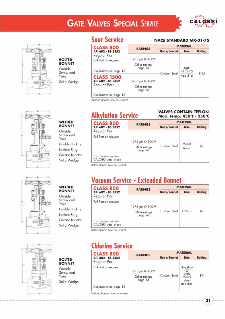
Sour Service NACE STANDARD MR-01-75
RATINGS
1975 psi @ 100°F
Other ratingspage 86
Carbon Steel
type410 HFStype 316
B7M
3705 psi @ 100°F
Other ratingspage 86
CLASS 800API 602 - BS 5352Regular Port
CLASS 1500API 602 - BS 5352Regular Port
Dimensions on page 18
Dimensions on page 18
Welded Bonnet type on request
Full Port on requestBOLTEDBONNETOutsideScrew andYokeSolid Wedge
MATERIALBody/Bonnet Trim Bolting
Alkylation ServiceVALVES CONTAIN TEFLONMax. temp. 450°F - 250°C
RATINGS
1975 psi @ 100°F
Other ratingspage 86
Carbon SteelMonelTeflon
B7
CLASS 800API 602 - BS 5352Regular Port
Bolted Bonnet type on request
Full Port on request
WELDEDBONNETOutsideScrew andYokeDouble PackingLantern RingGrease InjectorSolid Wedge
MATERIALBody/Bonnet Trim Bolting
VALVES CONTAIN TEFLONMax. temp. 450°F - 250°C
RATINGS
1975 psi @ 100°F
Other ratingspage 86
Carbon Steel 13% Cr B7
CLASS 800API 602 - BS 5352Regular Port
For dimensions seeCALOBRI data sheets
For dimensions seeCALOBRI data sheets
Bolted Bonnet type on request
Full Port on request
WELDEDBONNETOutsideScrew andYokeDouble PackingLantern RingGrease InjectorSolid Wedge
MATERIALBody/Bonnet Trim Bolting
Vacuum Service - Extended Bonnet
VALVES CONTAIN TEFLONMax. temp. 450°F - 250°C
RATINGS
1975 psi @ 100°F
Other ratingspage 86
Carbon Steel
Hastelloy"C"seatsMonelstem
and disc
B7
CLASS 800API 602 - BS 5352Regular Port
Dimensions on page 18
Welded Bonnet type on request
Full Port on request
BOLTEDBONNETOutsideScrew andYokeSolid Wedge
MATERIALBody/Bonnet Trim Bolting
Chlorine Service
GATE VALVES SPECIAL SERVICE
31

GATE VALVES OPTIONS
LOCKINGDEVICE
POSITIONINDICATOR
FLEXIBLEWEDGE
PTFEINSERT ON SEAT
GATE VALVES SPECIALITY PRODUCTS
THROUGH CONDUIT API 6D
THROUGH CONDUIT API 6A
API 6D CLASS MATERIALS
Design 600 Carbon Steel
Outside Screw 900/1500 Low Temp. Carbon Steel / Alloysand York 2500 Stainless Steel Alloys
Please refer to CALOBRI Thought Conduit Catalog C-TC02
API 6A CLASS MATERIALS
Design 3000 Carbon Steel
Inside Screw 5000 Low Temp. Carbon Steel / Alloysand York 10000 Stainless Steel Alloys
Please refer to CALOBRI Thought Conduit Catalog C-TC02
32

31
GLOBE VALVES
GLOBE VALVES
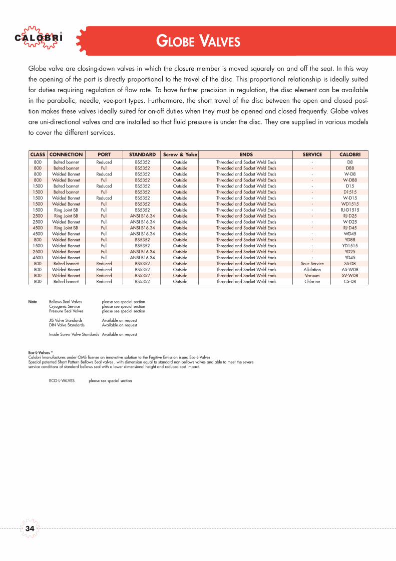
Globe valve are closing-down valves in which the closure member is moved squarely on and off the seat. In this waythe opening of the port is directly proportional to the travel of the disc. This proportional relationship is ideally suitedfor duties requiring regulation of flow rate. To have further precision in regulation, the disc element can be availablein the parabolic, needle, vee-port types. Furthermore, the short travel of the disc between the open and closed posi-tion makes these valves ideally suited for on-off duties when they must be opened and closed frequently. Globe valvesare uni-directional valves and are installed so that fluid pressure is under the disc. They are supplied in various modelsto cover the different services.
Note Bellows Seal Valves please see special sectionCryogenic Service please see special sectionPressure Seal Valves please see special section
JIS Valve Standards Available on requestDIN Valve Standards Available on request
Inside Screw Valve Standards Available on request
Eco-L-Valves ®
Calobri lmanufactures under OMB license an innovative solution to the Fugitive Emission issue: Eco-L-ValvesSpecial patented Short Pattern Bellows Seal valves , with dimension equal to standatd non-bellows valves and able to meet the severeservice conditions of standard bellows seal with a lower dimensional height and reduced cost impact.
ECO-L-VALVES please see special section
CLASS CONNECTION PORT STANDARD Screw & Yoke ENDS SERVICE CALOBRI800 Bolted bonnet Reduced BS5352 Outside Threaded and Socket Weld Ends - D8800 Bolted bonnet Full BS5352 Outside Threaded and Socket Weld Ends - D88800 Welded Bonnet Reduced BS5352 Outside Threaded and Socket Weld Ends - W-D8800 Welded Bonnet Full BS5352 Outside Threaded and Socket Weld Ends - W-D88
1500 Bolted bonnet Reduced BS5352 Outside Threaded and Socket Weld Ends - D151500 Bolted bonnet Full BS5352 Outside Threaded and Socket Weld Ends - D15151500 Welded Bonnet Reduced BS5352 Outside Threaded and Socket Weld Ends - W-D151500 Welded Bonnet Full BS5352 Outside Threaded and Socket Weld Ends - WD15151500 Ring Joint BB Full BS5352 Outside Threaded and Socket Weld Ends - RJ-D15152500 Ring Joint BB Full ANSI B16.34 Outside Threaded and Socket Weld Ends - RJ-D252500 Welded Bonnet Full ANSI B16.34 Outside Threaded and Socket Weld Ends - W-D254500 Ring Joint BB Full ANSI B16.34 Outside Threaded and Socket Weld Ends - RJ-D454500 Welded Bonnet Full ANSI B16.34 Outside Threaded and Socket Weld Ends - WD45800 Welded Bonnet Full BS5352 Outside Threaded and Socket Weld Ends - YD88
1500 Welded Bonnet Full BS5352 Outside Threaded and Socket Weld Ends - YD15152500 Welded Bonnet Full ANSI B16.34 Outside Threaded and Socket Weld Ends - YD254500 Welded Bonnet Full ANSI B16.34 Outside Threaded and Socket Weld Ends - YD45800 Bolted bonnet Reduced BS5352 Outside Threaded and Socket Weld Ends Sour Service SS-D8800 Welded Bonnet Reduced BS5352 Outside Threaded and Socket Weld Ends Alkilation AS-WD8800 Welded Bonnet Reduced BS5352 Outside Threaded and Socket Weld Ends Vacuum SV-WD8800 Bolted bonnet Reduced BS5352 Outside Threaded and Socket Weld Ends Chlorine CS-D8
34
GLOBE VALVES
Class 800 and 1500 Bolted Bonnet - Full and Reduced Bore

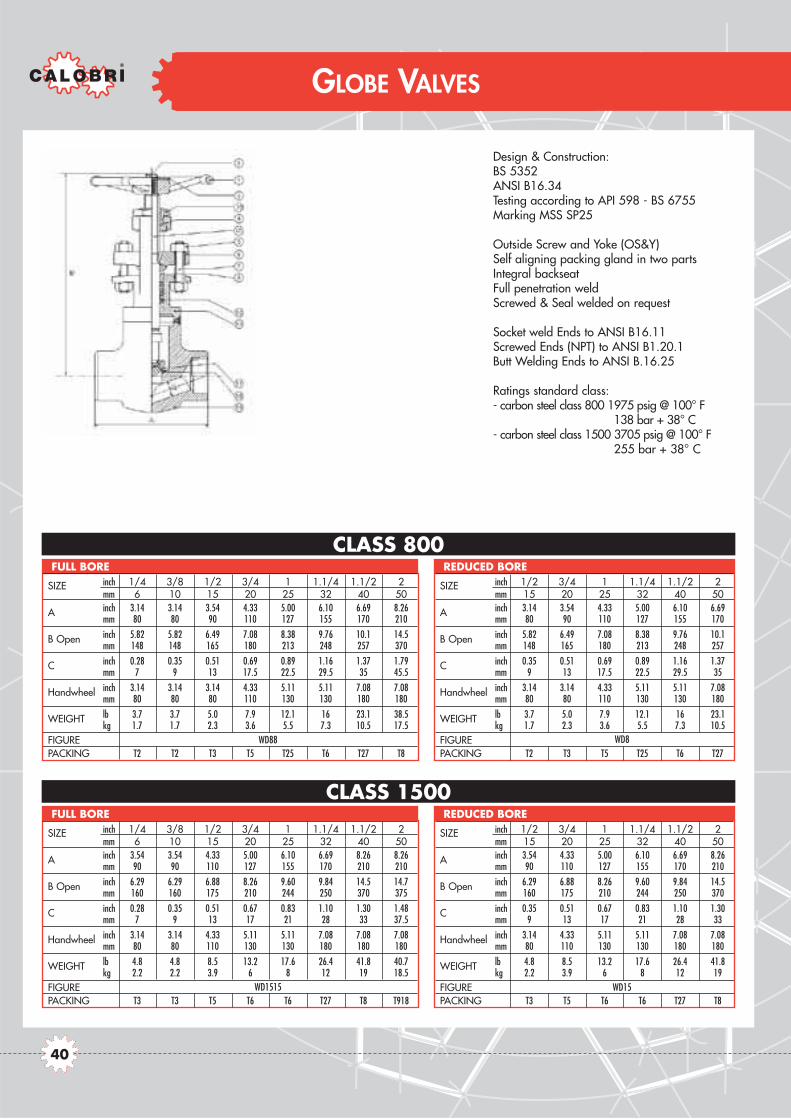
Design & Construction:BS 5352Testing according to API 598 - BS 6755Marking MSS SP25
Outside Screw and Yoke (OS&Y)Self aligning packing glandin two partsSpiral-wound gasket retained type IntegralbackseatSocket weld Ends to ANSI B16.11Screwed Ends (NPT) to ANSIB1.20.1Butt Welding Ends to ANSI B.16.25
Ratings:- carbon steel class 800 1975 psig @ 100° F
138 bar + 38° C- carbon steel class 1500 3705 psig @ 100° F
255 bar + 38° C
CLASS 1500
CLASS 800
GLOBE VALVES
SIZE inch 1/4 3/8 1/2 3/4 1 1.1/4 1.1/2 2mm 6 10 15 20 25 32 40 50
A inch 3.14 3.14 3.54 4.33 5.00 6.10 6.69 8.26mm 80 80 90 110 127 155 170 210
B Open inch 5.82 5.82 6.49 7.08 8.38 9.76 10.1 14.5mm 148 148 165 180 213 248 257 370
C inch 0.28 0.35 0.51 0.69 0.89 1.16 1.37 1.79mm 7 9 13 17.5 22.5 29.5 35 45.5
Handwheel inch 3.14 3.14 3.14 4.33 5.11 5.11 7.08 7.08mm 80 80 80 110 130 130 180 180
WEIGHT lb 3.7 3.7 5.0 7.9 12.1 16.5 25.5 48.5kg 1.7 1.7 2.3 3.6 5.5 7.5 11.6 22.0
FIGUREPACKING T2 T2 T3 T5 T25 T6 T27 T8GASKET 40x30 40x30 40x30 48x38 54x44 66x54 74x60 95x78
FULL BORE
SIZE inch 1/2 3/4 1 1.1/4 1.1/2 2mm 15 20 25 32 40 50
A inch 3.14 3.54 4.33 5.00 5.00 5.00mm 80 90 110 127 127 127
B Open inch 5.86 6.41 7.00 8.26 9.56 10.3mm 148 163 178 210 243 262
C inch 0.38 0.55 0.70 0.94 1.18 1.45mm 9.6 14 18 24 30 37
Handwheel inch 3.14 3.14 4.33 4.33 5.11 5.11mm 80 80 110 110 130 130
WEIGHT lb 3.5 4.8 7.7 11 13.8 17.6kg 1.6 2.2 3.5 5 6.3 8
FIGUREPACKING T2 T3 T5 T25 T6 T27GASKET 40x30 40x30 48x38 54x44 66x54 74x60
REDUCED BORE
SIZE inch 1/4 3/8 1/2 3/4 1 1.1/4 1.1/2 2mm 6 10 15 20 25 32 40 50
A inch 3.54 3.54 4.33 5.00 6.10 6.69 8.26 8.26mm 90 90 110 127 155 170 210 210
B Open inch 6.29 6.29 6.88 8.26 9.60 9.84 14.5 14.7mm 160 160 175 210 244 250 370 375
C inch 0.28 0.35 0.51 0.67 0.83 1.10 1.30 1.48mm 7 9 13 17 21 28 33 37.5
Handwheel inch 3.14 3.14 4.33 5.11 5.11 7.08 7.08 7.08mm 80 80 110 130 130 180 180 180
WEIGHT lb 4.8 4.8 8.5 13.2 17.6 26.4 51.7 50.6kg 2.2 2.2 3.9 6 8 12 23.5 23
FIGUREPACKING T3 T3 T5 T6 T6 T27 T8 T918GASKET 40x30 40x30 40x30 48x38 54x44 66x54 74x60 74x60
FULL BORE
SIZE inch 1/2 3/4 1 1.1/4 1.1/2 2mm 15 20 25 32 40 50
A inch 3.54 4.33 5.00 6.10 6.69 8.26mm 90 110 127 155 170 210
B Open inch 6.29 6.88 8.26 9.60 9.84 14.5mm 160 175 210 244 250 370
C inch 0.35 0.51 0.67 0.83 1.10 1.30mm 9 13 17 21 28 33
Handwheel inch 3.14 4.33 5.11 5.11 7.08 7.08mm 80 110 130 130 180 180
WEIGHT lb 4.8 8.5 13.2 17.6 26.4 51.7kg 2.2 3.9 6 8 12 23.5
FIGUREPACKING T3 T5 T6 T6 T27 T8GASKET 40x30 40x30 48x38 54x44 66x54 74x60
REDUCED BORE
D88 D8
D1515 D15
36
GLOBE VALVES
Class 1500 and 2500 Bolted Bonnet - Full Bore
CLASS 2500
CLASS 1500
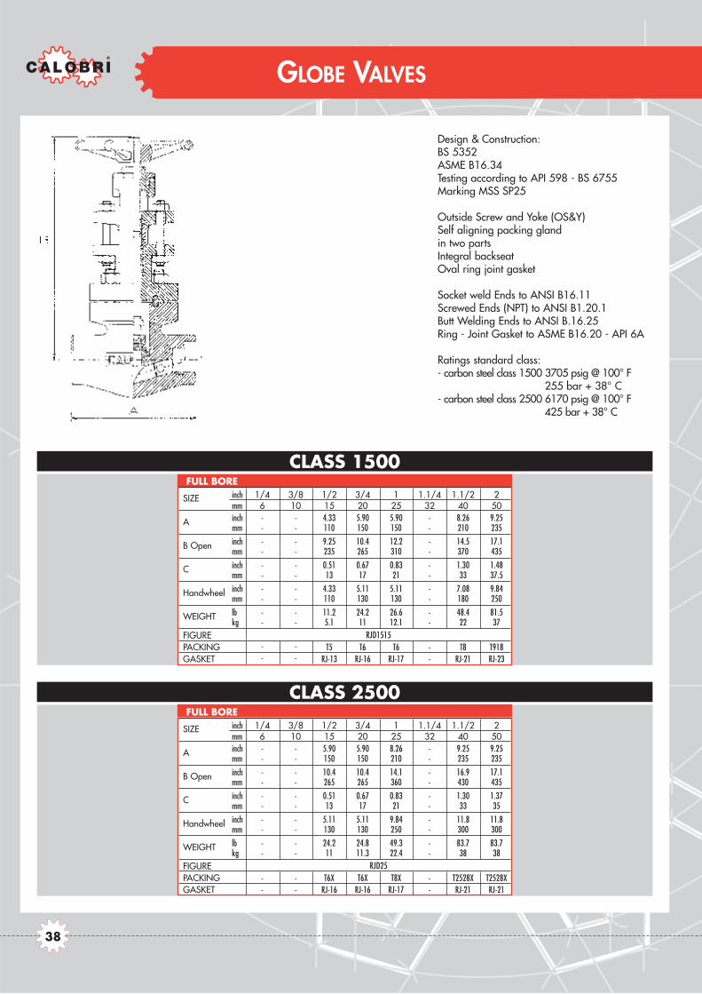
Design & Construction:BS 5352ASME B16.34Testing according to API 598 - BS 6755Marking MSS SP25
Outside Screw and Yoke (OS&Y)Self aligning packing glandin two partsIntegral backseatOval ring joint gasket
Socket weld Ends to ANSI B16.11Screwed Ends (NPT) to ANSI B1.20.1Butt Welding Ends to ANSI B.16.25Ring - Joint Gasket to ASME B16.20 - API 6A
Ratings standard class:- carbon steel class 1500 3705 psig @ 100° F
255 bar + 38° C- carbon steel class 2500 6170 psig @ 100° F
425 bar + 38° C
GLOBE VALVES
SIZE inch 1/4 3/8 1/2 3/4 1 1.1/4 1.1/2 2mm 6 10 15 20 25 32 40 50
A inch - - 4.33 5.90 5.90 - 8.26 9.25mm - - 110 150 150 - 210 235
B Open inch - - 9.25 10.4 12.2 - 14.5 17.1mm - - 235 265 310 - 370 435
C inch - - 0.51 0.67 0.83 - 1.30 1.48mm - - 13 17 21 - 33 37.5
Handwheel inch - - 4.33 5.11 5.11 - 7.08 9.84mm - - 110 130 130 - 180 250
WEIGHT lb - - 11.2 24.2 26.6 - 48.4 81.5kg - - 5.1 11 12.1 - 22 37
FIGUREPACKING - - T5 T6 T6 - T8 T918GASKET - - RJ-13 RJ-16 RJ-17 - RJ-21 RJ-23
FULL BORE
SIZE inch 1/4 3/8 1/2 3/4 1 1.1/4 1.1/2 2mm 6 10 15 20 25 32 40 50
A inch - - 5.90 5.90 8.26 - 9.25 9.25mm - - 150 150 210 - 235 235
B Open inch - - 10.4 10.4 14.1 - 16.9 17.1mm - - 265 265 360 - 430 435
C inch - - 0.51 0.67 0.83 - 1.30 1.37mm - - 13 17 21 - 33 35
Handwheel inch - - 5.11 5.11 9.84 - 11.8 11.8mm - - 130 130 250 - 300 300
WEIGHT lb - - 24.2 24.8 49.3 - 83.7 83.7kg - - 11 11.3 22.4 - 38 38
FIGUREPACKING - - T6X T6X T8X - T2528X T2528XGASKET - - RJ-16 RJ-16 RJ-17 - RJ-21 RJ-21
FULL BORE
RJD1515
RJD25
38

GLOBE VALVES
Class 800 and 1500 Welded Bonnet - Full and Reduced Bore
CLASS 1500
CLASS 800
GLOBE VALVES
Design & Construction:BS 5352ANSI B16.34Testing according to API 598 - BS 6755Marking MSS SP25
Outside Screw and Yoke (OS&Y)Self aligning packing gland in two partsIntegral backseatFull penetration weldScrewed & Seal welded on request
Socket weld Ends to ANSI B16.11Screwed Ends (NPT) to ANSI B1.20.1Butt Welding Ends to ANSI B.16.25
Ratings standard class:- carbon steel class 800 1975 psig @ 100° F
138 bar + 38° C- carbon steel class 1500 3705 psig @ 100° F
255 bar + 38° C
SIZE inch 1/4 3/8 1/2 3/4 1 1.1/4 1.1/2 2mm 6 10 15 20 25 32 40 50
A inch 3.14 3.14 3.54 4.33 5.00 6.10 6.69 8.26mm 80 80 90 110 127 155 170 210
B Open inch 5.82 5.82 6.49 7.08 8.38 9.76 10.1 14.5mm 148 148 165 180 213 248 257 370
C inch 0.28 0.35 0.51 0.69 0.89 1.16 1.37 1.79mm 7 9 13 17.5 22.5 29.5 35 45.5
Handwheel inch 3.14 3.14 3.14 4.33 5.11 5.11 7.08 7.08mm 80 80 80 110 130 130 180 180
WEIGHT lb 3.7 3.7 5.0 7.9 12.1 16 23.1 38.5kg 1.7 1.7 2.3 3.6 5.5 7.3 10.5 17.5
FIGUREPACKING T2 T2 T3 T5 T25 T6 T27 T8
FULL BORE
SIZE inch 1/4 3/8 1/2 3/4 1 1.1/4 1.1/2 2mm 6 10 15 20 25 32 40 50
A inch 3.54 3.54 4.33 5.00 6.10 6.69 8.26 8.26mm 90 90 110 127 155 170 210 210
B Open inch 6.29 6.29 6.88 8.26 9.60 9.84 14.5 14.7mm 160 160 175 210 244 250 370 375
C inch 0.28 0.35 0.51 0.67 0.83 1.10 1.30 1.48mm 7 9 13 17 21 28 33 37.5
Handwheel inch 3.14 3.14 4.33 5.11 5.11 7.08 7.08 7.08mm 80 80 110 130 130 180 180 180
WEIGHT lb 4.8 4.8 8.5 13.2 17.6 26.4 41.8 40.7kg 2.2 2.2 3.9 6 8 12 19 18.5
FIGUREPACKING T3 T3 T5 T6 T6 T27 T8 T918
FULL BORE
SIZE inch 1/2 3/4 1 1.1/4 1.1/2 2mm 15 20 25 32 40 50
A inch 3.14 3.54 4.33 5.00 6.10 6.69mm 80 90 110 127 155 170
B Open inch 5.82 6.49 7.08 8.38 9.76 10.1mm 148 165 180 213 248 257
C inch 0.35 0.51 0.69 0.89 1.16 1.37mm 9 13 17.5 22.5 29.5 35
Handwheel inch 3.14 3.14 4.33 5.11 5.11 7.08mm 80 80 110 130 130 180
WEIGHT lb 3.7 5.0 7.9 12.1 16 23.1kg 1.7 2.3 3.6 5.5 7.3 10.5
FIGUREPACKING T2 T3 T5 T25 T6 T27
REDUCED BORE
SIZE inch 1/2 3/4 1 1.1/4 1.1/2 2mm 15 20 25 32 40 50
A inch 3.54 4.33 5.00 6.10 6.69 8.26mm 90 110 127 155 170 210
B Open inch 6.29 6.88 8.26 9.60 9.84 14.5mm 160 175 210 244 250 370
C inch 0.35 0.51 0.67 0.83 1.10 1.30mm 9 13 17 21 28 33
Handwheel inch 3.14 4.33 5.11 5.11 7.08 7.08mm 80 110 130 130 180 180
WEIGHT lb 4.8 8.5 13.2 17.6 26.4 41.8kg 2.2 3.9 6 8 12 19
FIGUREPACKING T3 T5 T6 T6 T27 T8
REDUCED BORE
WD88 WD8
WD1515 WD15
40

GLOBE VALVES
Class 2500 and 4500 Welded Bonnet - Full Bore

CLASS 4500
CLASS 2500
Design construction:BS 5352ASME B16.34Testing according to API 598 - BS 6755Marking MSS SP25
Outside Screw and Yoke (OS&Y)Self aligning packing gland in two partsIntegral backseatFull penetration weld
Socket weld Ends to ANSI B16.11Screwed Ends (NPT) to ANSI B1.20.1Butt Welding Ends to ANSI B.16.25
Ratings standard class:- carbon steel class 2500 6170 psig @ 100° F
425 bar + 38° C- carbon steel class 4500 11110 psig @ 100° F
765 bar + 38° C
GLOBE VALVES
SIZE inch 1/4 3/8 1/2 3/4 1 1.1/4 1.1/2 2mm 6 10 15 20 25 32 40 50
A inch - - 5.00 6.10 6.69 - 9.25 9.25mm - - 127 155 170 - 235 235
B Open inch - - 9.33 9.52 10.1 - 16.9 17.1mm - - 237 242 256 - 430 435
C inch - - 0.51 0.67 0.83 - 1.30 1.37mm - - 13 17 21 - 33 35
Handwheel inch - - 5.11 5.11 5.11 - 11.8 11.8mm - - 130 130 130 - 300 300
WEIGHT lb - - 14.3 18.7 27.5 - 57.2 56.1kg - - 6.5 8.5 12.5 - 26 25.5
FIGUREPACKING - - T6X T6X T8X - T2528X T2528X
FULL BORE
SIZE inch 1/4 3/8 1/2 3/4 1 1.1/4 1.1/2 2mm 6 10 15 20 25 32 40 50
A inch - - 6.10 6.69 8.26 - 9.25 -mm - - 155 170 210 - 235 -
B Open inch - - 9.44 11.2 13.7 - 16.1 -mm - - 240 250 350 - 410 -
C inch - - 0.43 0.43 0.55 - 1.10 -mm - - 11 11 14 - 28 -
Handwheel inch - - 7.08 9.84 9.84 - 11.8 -mm - - 180 250 250 - 300 -
WEIGHT lb - - 19.8 28.6 53.9 - 61.7 -kg - - 9 13 24.5 - 28 -
FIGUREPACKING - - T6X T8X T8X - T2528X -
FULL BORE
WD25
WD45
42

GLOBE VALVES
Class 800 - 1500 - 2500 - 4500 Welded Bonnet - Full Bore (Y type)

CLASS 800 CLASS 2500-2700
CLASS 1500-1700 CLASS 4500
Design & Construction:BS 5352ASME B16.34Testing according to API 598 - BS 6755Marking MSS SP25
Outside Screw and Yoke (OS&Y)Self aligning packing gland in two partsIntegral backseatFull penetration weld
Socket weld Ends to ANSI B16.11Screwed Ends (NPT) to ANSI B1.20.1Butt Welding Ends to ANSI B.16.25
Ratings standard class:- carbon steel class 800 1975 psig @ 100° F
138 bar + 38° C- carbon steel class 1500 3705 psig @ 100° F
255 bar + 38° C- carbon steel class 2500 6170 psig @ 100° F
425 bar + 38° C- carbon steel class 4500 11110 psig @ 100° F
765 bar + 38° C
GLOBE VALVES
SIZE inch 1/4 3/8 1/2 3/4 1 1.1/4 1.1/2 2mm 6 10 15 20 25 32 40 50
A inch 3.54 3.54 3.54 3.54 5.00 5.00 6.10 7.08mm 90 90 90 90 127 127 155 180
B Open inch 6.10 6.10 6.10 6.88 8.66 9.44 11.02 13.78mm 155 155 155 175 220 240 280 350
C inch 0.27 0.35 0.51 0.68 0.88 1.16 1.37 1.79mm 7 9 13 17.5 22.5 29.5 35 45.5
Handwheel inch 3.14 3.14 3.14 4.33 5.11 5.11 7.08 7.08mm 80 80 80 110 130 130 180 180
WEIGHT lb 3.3 3.3 3.3 4.4 9.2 11 19.8 28.6kg 1.5 1.5 1.5 2 4.2 5 9 13
FIGUREPACKING T4 T4 T4 T5 T25 T6 T27 T8
FULL BORE
SIZE inch 1/4 3/8 1/2 3/4 1 1.1/4 1.1/2 2mm 6 10 15 20 25 32 40 50
A inch 5.00 5.00 5.00 5.00 6.10 6.10 7.08 8.86mm 127 127 127 127 155 155 180 225
B Open inch 11.02 11.02 11.02 11.02 14.1 14.56 16.53 21.2mm 280 280 280 280 370 370 420 540
C inch 0.27 0.35 0.43 0.59 0.76 1.08 1.24 1.53mm 7 9 11 15 19.5 27.5 31.5 39
Handwheel inch 5.11 5.11 5.11 5.11 7.08 7.08 7.08 11.8mm 130 130 130 130 180 180 180 300
WEIGHT lb 9.9 9.9 9.9 15.6 16.7 21.5 37.8 79.5kg 4.5 4.5 4.5 7.1 7.6 9.8 17.1 36
FIGUREPACKING T2513X T2513X T2513X T2513X T8X T8X T918X T2528X
FULL BORE
SIZE inch 1/4 3/8 1/2 3/4 1 1.1/4 1.1/2 2mm 6 10 15 20 25 32 40 50
A inch 3.54 3.54 3.54 5.00 5.00 6.10 6.10 7.08mm 90 90 90 127 127 155 155 180
B Open inch 7.08 7.08 7.08 9.44 9.84 11.02 14.96 16.53mm 180 180 180 240 250 280 380 420
C inch 0.27 0.35 0.43 0.59 0.76 1.08 1.24 1.53mm 7 9 11 15 19.5 27.5 31.5 39
Handwheel inch 4.33 4.33 4.33 5.11 5.11 7.08 7.08 7.08mm 110 110 110 130 130 180 180 180
WEIGHT lb 4.4 4.4 4.4 9.2 11.4 20.9 23.1 29.8kg 2 2 2 4.2 5.2 9.5 10.5 13.5
FIGUREPACKING T5 T5 T5 T6 T6 T27 T8 T918
FULL BORE
SIZE inch 1/4 3/8 1/2 3/4 1 1.1/4 1.1/2 2mm 6 10 15 20 25 32 40 50
A inch 6.10 6.10 6.10 6.10 6.10 - 8.86 8.86mm 155 155 155 155 155 - 225 225
B Open inch 13.77 13.77 13.77 13.77 14.96 - 17.83 17.83mm 350 350 350 350 380 - 453 453
C inch 0.27 0.35 0.43 0.43 0.59 - 1.02 1.10mm 7 9 11 11 15 - 26 28
Handwheel inch 7.08 7.08 7.08 7.08 7.08 - 15.75 15.75mm 180 180 180 180 180 - 400 400
WEIGHT lb 21.1 21.1 21.1 20.7 23.1 - 75.0 79.5kg 9.6 9.6 9.6 9.4 10.5 - 34 36
FIGUREPACKING T8X T8X T8X T8X T8X - T2528X T2528X
FULL BORE
YD88 YD25
YD1515 YD45
44
GLOBE VALVES SPECIAL SERVICE
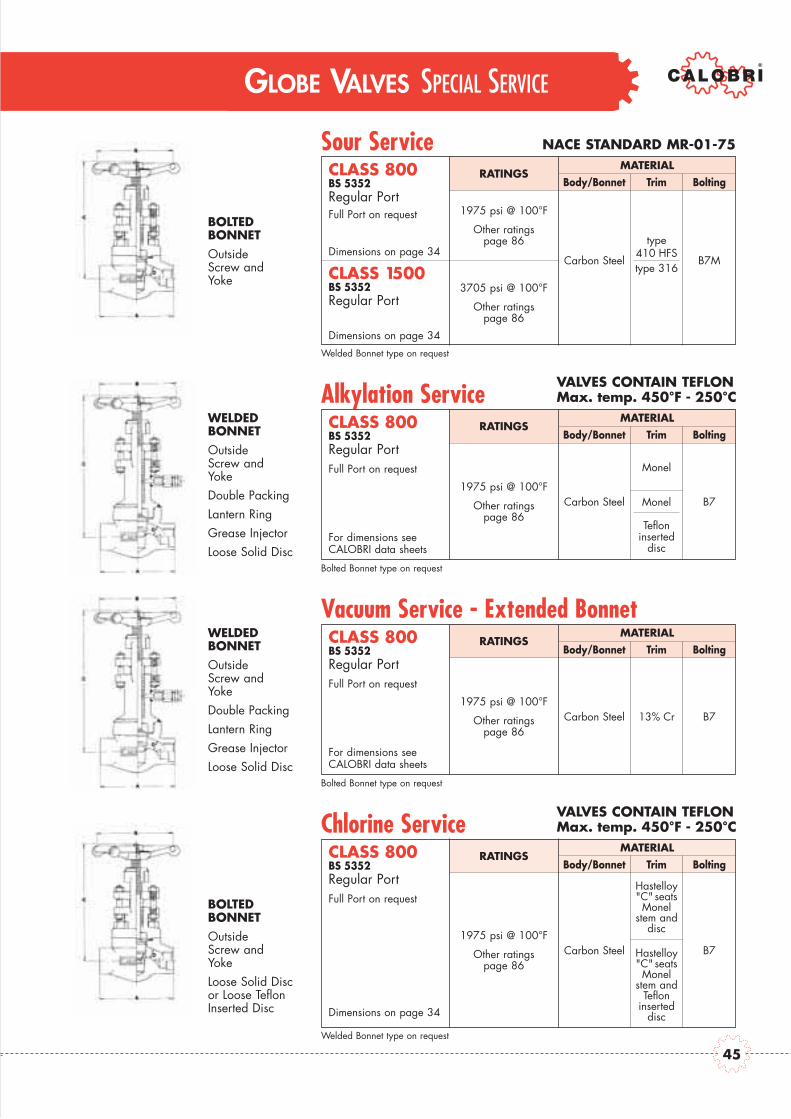
Sour Service NACE STANDARD MR-01-75
RATINGS
1975 psi @ 100°F
Other ratingspage 86
Carbon Steel
type410 HFStype 316
B7M
3705 psi @ 100°F
Other ratingspage 86
CLASS 800BS 5352Regular Port
CLASS 1500BS 5352Regular Port
Dimensions on page 34
Dimensions on page 34
Welded Bonnet type on request
Full Port on requestBOLTEDBONNETOutsideScrew andYoke
MATERIALBody/Bonnet Trim Bolting
Alkylation ServiceVALVES CONTAIN TEFLONMax. temp. 450°F - 250°C
RATINGS
1975 psi @ 100°F
Other ratingspage 86
Carbon Steel Monel
Tefloninserted
disc
B7
CLASS 800BS 5352Regular Port
Bolted Bonnet type on request
Full Port on request
WELDEDBONNETOutsideScrew andYokeDouble PackingLantern RingGrease InjectorLoose Solid Disc
MATERIALBody/Bonnet Trim Bolting
VALVES CONTAIN TEFLONMax. temp. 450°F - 250°C
RATINGS
1975 psi @ 100°F
Other ratingspage 86
Carbon Steel 13% Cr B7
CLASS 800BS 5352Regular Port
For dimensions seeCALOBRI data sheets
For dimensions seeCALOBRI data sheets
Bolted Bonnet type on request
Full Port on request
WELDEDBONNETOutsideScrew andYokeDouble PackingLantern RingGrease InjectorLoose Solid Disc
MATERIALBody/Bonnet Trim Bolting
Vacuum Service - Extended Bonnet
VALVES CONTAIN TEFLONMax. temp. 450°F - 250°C
RATINGS
Welded Bonnet type on request
BOLTEDBONNETOutsideScrew andYokeLoose Solid Discor Loose TeflonInserted Disc
MATERIALBody/Bonnet Trim Bolting
Chlorine Service
Monel
1975 psi @ 100°F
Other ratingspage 86
Carbon Steel
Hastelloy"C" seatsMonel
stem anddisc
Hastelloy"C" seatsMonel
stem andTeflon
inserteddisc
B7
CLASS 800BS 5352Regular Port
Dimensions on page 34
Full Port on request
45

POSITIONINDICATOR
NEEDLEPOINTRENEWABLEOR INTEGRALSEAT
LOOSE DISCNEEDLEPOINTRENEWABLEOR INTEGRALSEAT
LOOSE “V”PORT DISCRENEWABLEOR INTEGRALSEAT
GLOBE VALVES SPECIALITY PRODUCTS
SELF CLOSING - LEVER OPERATED
INSTRUMENTATION VALVE
VERTICAL CHECK
Figure CLASS MATERIALS
SC-8 800 Carbon Steel
SC-15 1500 Alloy Steels
Flanged and BW ends available Stainless Steel Alloys
Figure CLASS MATERIALS
UV-88 800 Carbon Steel
UV-1515 1500 Stainless Steels
Exotics and Alloys
Figure CLASS MATERIALS
30 3000 Carbon Steel
60 6000 Stainless Steel
BOLTED BONNETOutside Screw & Yoke
Spring operated
THREADED BONNET
Forged Steel Construction
THREADED BONNET
Forged Steel Construction
Please contact CALOBRI offices for dimensional data
Please contact CALOBRI offices for dimensional data
Please contact CALOBRI offices for dimensional data
GLOBE VALVES OPTIONS
46

CHECK VALVES
CHECK VALVES
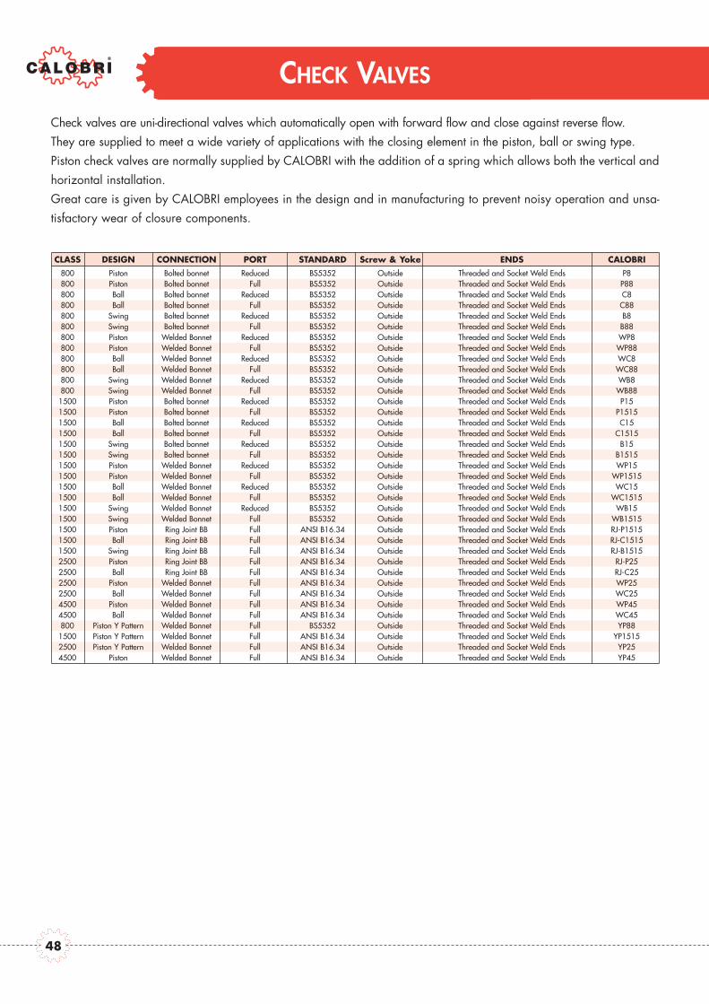
Check valves are uni-directional valves which automatically open with forward flow and close against reverse flow.They are supplied to meet a wide variety of applications with the closing element in the piston, ball or swing type.Piston check valves are normally supplied by CALOBRI with the addition of a spring which allows both the vertical andhorizontal installation.Great care is given by CALOBRI employees in the design and in manufacturing to prevent noisy operation and unsa-tisfactory wear of closure components.
CLASS DESIGN CONNECTION PORT STANDARD Screw & Yoke ENDS CALOBRI800 Piston Bolted bonnet Reduced BS5352 Outside Threaded and Socket Weld Ends P8800 Piston Bolted bonnet Full BS5352 Outside Threaded and Socket Weld Ends P88800 Ball Bolted bonnet Reduced BS5352 Outside Threaded and Socket Weld Ends C8800 Ball Bolted bonnet Full BS5352 Outside Threaded and Socket Weld Ends C88800 Swing Bolted bonnet Reduced BS5352 Outside Threaded and Socket Weld Ends B8800 Swing Bolted bonnet Full BS5352 Outside Threaded and Socket Weld Ends B88800 Piston Welded Bonnet Reduced BS5352 Outside Threaded and Socket Weld Ends WP8800 Piston Welded Bonnet Full BS5352 Outside Threaded and Socket Weld Ends WP88800 Ball Welded Bonnet Reduced BS5352 Outside Threaded and Socket Weld Ends WC8800 Ball Welded Bonnet Full BS5352 Outside Threaded and Socket Weld Ends WC88800 Swing Welded Bonnet Reduced BS5352 Outside Threaded and Socket Weld Ends WB8800 Swing Welded Bonnet Full BS5352 Outside Threaded and Socket Weld Ends WB88
1500 Piston Bolted bonnet Reduced BS5352 Outside Threaded and Socket Weld Ends P151500 Piston Bolted bonnet Full BS5352 Outside Threaded and Socket Weld Ends P15151500 Ball Bolted bonnet Reduced BS5352 Outside Threaded and Socket Weld Ends C151500 Ball Bolted bonnet Full BS5352 Outside Threaded and Socket Weld Ends C15151500 Swing Bolted bonnet Reduced BS5352 Outside Threaded and Socket Weld Ends B151500 Swing Bolted bonnet Full BS5352 Outside Threaded and Socket Weld Ends B15151500 Piston Welded Bonnet Reduced BS5352 Outside Threaded and Socket Weld Ends WP151500 Piston Welded Bonnet Full BS5352 Outside Threaded and Socket Weld Ends WP15151500 Ball Welded Bonnet Reduced BS5352 Outside Threaded and Socket Weld Ends WC151500 Ball Welded Bonnet Full BS5352 Outside Threaded and Socket Weld Ends WC15151500 Swing Welded Bonnet Reduced BS5352 Outside Threaded and Socket Weld Ends WB151500 Swing Welded Bonnet Full BS5352 Outside Threaded and Socket Weld Ends WB15151500 Piston Ring Joint BB Full ANSI B16.34 Outside Threaded and Socket Weld Ends RJ-P15151500 Ball Ring Joint BB Full ANSI B16.34 Outside Threaded and Socket Weld Ends RJ-C15151500 Swing Ring Joint BB Full ANSI B16.34 Outside Threaded and Socket Weld Ends RJ-B15152500 Piston Ring Joint BB Full ANSI B16.34 Outside Threaded and Socket Weld Ends RJ-P252500 Ball Ring Joint BB Full ANSI B16.34 Outside Threaded and Socket Weld Ends RJ-C252500 Piston Welded Bonnet Full ANSI B16.34 Outside Threaded and Socket Weld Ends WP252500 Ball Welded Bonnet Full ANSI B16.34 Outside Threaded and Socket Weld Ends WC254500 Piston Welded Bonnet Full ANSI B16.34 Outside Threaded and Socket Weld Ends WP454500 Ball Welded Bonnet Full ANSI B16.34 Outside Threaded and Socket Weld Ends WC45800 Piston Y Pattern Welded Bonnet Full BS5352 Outside Threaded and Socket Weld Ends YP88
1500 Piston Y Pattern Welded Bonnet Full ANSI B16.34 Outside Threaded and Socket Weld Ends YP15152500 Piston Y Pattern Welded Bonnet Full ANSI B16.34 Outside Threaded and Socket Weld Ends YP254500 Piston Welded Bonnet Full ANSI B16.34 Outside Threaded and Socket Weld Ends YP45
48

CHECK VALVES
Class 800 and 1500 Bolted Bonnet - Full and Reduced Bore

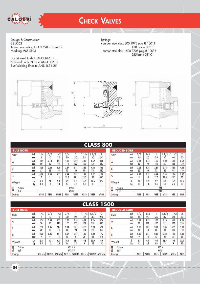
Design & Construction:BS 5352Testing according to API 598 - BS 6755Marking MSS SP25
Spiral-wound gasket retained type- carbon steel class 800 1975 psig @ 100° F
138 bar + 38° C- carbon steel class 1500 3705 psig @ 100° F
255 bar + 38° C
CLASS 1500
CLASS 800
CHECK VALVES
SIZE inch 1/4 3/8 1/2 3/4 1 1.1/4 1.1/2 2mm 6 10 15 20 25 32 40 50
Piston - Ball inch 3.14 3.14 3.54 4.33 5.00 6.10 6.69 8.26
Amm 80 80 90 110 127 155 170 210
Swing inch 3.14 3.14 3.54 4.33 5.00 5.00 5.00 8.26mm 80 80 90 110 127 127 127 210
B inch 2.08 2.08 2.36 2.87 3.14 3.85 4.64 5.90mm 53 53 60 73 80 98 118 15
Piston - Ball inch 0.28 0.35 0.51 0.69 0.88 1.16 1.38 1.79
Cmm 7 9 13 17.5 22.5 29.5 35 45.5
Swing inch 0.31 0.38 0.55 0.70 0.94 1.18 1.45 1.89mm 8 9.6 14 18 24 30 37 48
Piston - Ball Lb 2.8 2.8 3.0 5.2 8.8 16.2 17.6 39.6Kg 1.3 1.3 1.4 2.4 4.0 7.4 8 18
Swing lb 2.8 2.8 3.0 5.2 8.8 12.1 14.3 38.5kg 1.3 1.3 1.4 2.4 4.0 5.5 6.5 17.5
Piston Ball Swing
GASKET 40x30 40x30 40x30 48x38 54x44 66x54 74x60 95x78
FULL BORE
Wei
ght
FIG
URE
SIZE inch 1/2 3/4 1 1.1/4 1.1/2 2mm 15 20 25 32 40 50
Piston - Ball inch 3.14 3.54 4.33 5.00 6.10 6.69
Amm 80 90 110 127 155 170
Swing inch 3.14 3.54 4.33 5.00 5.00 5.00mm 80 90 110 127 127 127
B inch 2.08 2.36 2.87 3.14 3.85 4.64mm 53 60 73 80 98 118
Piston - Ball inch 0.35 0.51 0.69 0.88 1.16 1.38
Cmm 9 13 17.5 22.5 29.5 35
Swing inch 0.38 0.55 0.70 0.94 1.18 1.45mm 9.6 14 18 24 30 37
Piston - Ball Lb 2.8 3.0 5.2 8.8 16.2 17.6Kg 1.3 1.4 2.4 4.0 7.4 8
Swing lb 2.8 3.0 5.2 8.8 12.1 14.3kg 1.3 1.4 2.4 4.0 5.5 6.5
Piston Ball Swing
GASKET 40x30 40x30 48x38 54x44 66x54 74x60
REDUCED BORE
Wei
ght
FIG
URE
SIZE inch 1/2 3/4 1 1.1/4 1.1/2 2mm 15 20 25 32 40 50
Piston - Ball inch 3.54 4.33 5.00 6.10 6.69 8.26
Amm 90 110 127 155 170 210
Swing inch 3.54 4.33 5.00 5.00 5.00 8.26mm 90 110 127 127 127 210
B inch 2.36 2.87 3.14 3.85 4.64 5.90mm 60 73 80 98 118 150
Piston - Ball inch 0.35 0.51 0.69 0.83 1.10 1.30
Cmm 9 13 17.5 21 28 33
Swing inch 0.38 0.55 0.70 0.94 1.18 1.45mm 9.6 14 18 24 30 37
Piston - Ball Lb 3.3 6.1 10.1 16.2 19.8 49.9Kg 1.5 2.8 4.6 7.4 9 19.5
Swing lb 3.3 5.2 8.8 13.2 20.9 41.8kg 1.5 2.4 4 6 9.5 19
Piston Ball Swing
GASKET 40x30 40x30 48x38 54x44 66x54 74x60
REDUCED BORE
Wei
ght
FIG
URE
SIZE inch 1/4 3/8 1/2 3/4 1 1.1/4 1.1/2 2mm 6 10 15 20 25 32 40 50
Piston - Ball inch 3.54 3.54 4.33 5.00 6.10 6.69 8.26 8.26
Amm 90 90 110 127 155 170 210 210
Swing inch 3.54 3.54 4.33 5.00 5.00 5.00 8.26 8.26mm 90 90 110 127 127 127 210 210
B inch 2.36 2.36 2.87 3.14 3.85 4.64 5.90 5.90mm 60 60 73 80 98 118 150 150
Piston - Ball inch 0.28 0.35 0.51 0.69 0.83 1.10 1.30 1.48C mm 7 9 13 17.5 21 28 33 37.5
Swing inch 0.31 0.38 0.55 0.70 0.94 1.18 1.45 1.57mm 8 9.6 14 18 24 30 37 40
Piston - Ball Lb 3.3 3.3 6.1 10.1 16.2 19.8 49.9 41.8Kg 1.5 1.5 2.8 4.6 7.4 9 19.5 19
Swing lb 3.5 3.3 5.2 8.8 13.2 20.9 41.8 18.5kg 1.6 1.5 2.4 4.0 6 9.5 19 40.7
Piston Ball Swing
GASKET 40x30 40x30 40x30 48x38 54x44 66x54 74x60 74x60
FULL BORE
Wei
ght
FIG
URE
P88C88B88
P8C8B8
P1515C1515B1515
P15C15B15
50

CHECK VALVES
Class 1500 and 2500 Bolted Bonnet - Full Bore

Design construction:BS 5352ASME B16.34Testing according to API 598 - BS 6755Marking MSS SP25
Socket weld Ends to ANSI B16.11Screwed Ends (NPT) to ANSI B1.20.1Butt Welding Ends to ANSI B.16.25Ring - Joint Gasket to ASME B16.20 - API 6A
Ratings:- carbon steel class 1500 3705 psig @ 100° F
255 bar + 38° C- carbon steel class 2500 6170 psig @ 100° F
425 bar + 38° C
CLASS 2500
CLASS 1500
CHECK VALVES
SIZE inch 1/4 3/8 1/2 3/4 1 1.1/4 1.1/2 2mm 6 10 15 20 25 32 40 50
A inch - - 4.33 5.90 5.90 - 8.26 9.25mm - - 110 150 150 - 210 235
B inch - - 3.93 5.11 5.70 - 6.29 7.67mm - - 100 130 145 - 160 195
Piston - Ball inch - - 0.51 0.67 0.83 - 1.30 1.48
Cmm - - 13 17 21 - 33 37.5
Swing inch - - 0.55 0.70 0.94 - 1.45 1.89mm - - 14 18 24 - 37 48
Piston - Ball Lb - - 8.8 16.5 19.8 - 40.7 66Kg - - 4 7.5 9 - 18.5 30
Swing lb - - 8.37 15.4 18.7 - 38.5 63.8kg - - 3.8 7 8.5 - 17.5 29
PistonBall Swing
RING JOINT - - RJ-13 RJ-16 RJ-17 - RJ-21 RJ-23
FULL BORE
Wei
ght
FIG
URE
SIZE inch 1/4 3/8 1/2 3/4 1 1.1/4 1.1/2 2mm 6 10 15 20 25 32 40 50
A inch - - 5.90 5.90 8.26 - 9.25 9.25mm - - 150 150 210 - 235 235
B inch - - 5.11 5.11 6.29 - 7.67 7.67mm - - 130 130 160 - 195 195
C inch - - 0.51 0.67 0.83 - 1.30 1.37mm - - 13 17 21 - 33 35
Weight Lb - - 15.4 14.9 38.5 - 63.8 63.8Kg - - 7 6.8 17.5 - 29 29
Piston Ball
RING JOINT - - RJ-16 RJ-16 RJ-17 - RJ-21 RJ-21
FULL BORE
FIGUR
E
RJP1515RJC1515
RJP25RJC25
RJB1515
52

CHECK VALVES
Class 800 and 1500 Welded Bonnet - Full and Reduced Bore
Design & Construction:BS 5352Testing according to API 598 - BS 6755Marking MSS SP25
Socket weld Ends to ANSI B16.11Screwed Ends (NPT) to ANSIB1.20.1Butt Welding Ends to ANSI B.16.25
Ratings:- carbon steel class 800 1975 psig @ 100° F
138 bar + 38° C- carbon steel class 1500 3705 psig @ 100° F
255 bar + 38° C
CLASS 1500
CLASS 800
CHECK VALVES
SIZE inch 1/4 3/8 1/2 3/4 1 1.1/4 1.1/2 2mm 6 10 15 20 25 32 40 50
A inch 3.14 3.14 3.54 4.33 5.00 6.10 6.69 8.26mm 80 80 90 110 127 155 170 210
B inch 2.08 2.08 2.36 2.87 3.14 3.85 4.33 5.90mm 53 53 60 73 80 98 110 150
C inch 0.28 0.35 0.51 0.69 0.88 1.16 1.37 1.79mm 7 9 13 17.5 22.5 29.5 35 45.5
Weight Lb 2.8 2.8 3.0 5.2 8.8 16.3 17.6 37.4Kg 1.3 1.3 1.4 2.4 4.0 7.4 8 17
Piston Ball
Swing WB88 WB88 WB88 WB88 WB88 WB88 WB88 WB88
FULL BORE
FIGUR
E
SIZE inch 1/4 3/8 1/2 3/4 1 1.1/4 1.1/2 2mm 6 10 15 20 25 32 40 50
A inch 3.54 3.54 4.33 5.00 6.10 6.69 8.26 8.26mm 90 90 110 127 155 170 210 210
B inch 2.36 2.36 2.87 3.14 3.85 4.33 5.90 5.90mm 60 60 73 80 98 110 150 150
C inch 0.28 0.35 0.51 0.67 0.83 1.10 1.30 1.47mm 7 9 13 17 21 28 33 37.5
Weight Lb 3.3 3.3 6.1 10.1 16.3 19.8 33.0 31.9Kg 1.5 1.5 2.8 4.6 7.4 9 15 14.5
PistonBall
Swing WB1515 WB1515 WB1515 WB1515 WB1515 WB1515 WB1515 WB1515
FULL BORE
FIGUR
E
SIZE inch 1/2 3/4 1 1.1/4 1.1/2 2mm 15 20 25 32 40 50
A inch 3.14 3.54 4.33 5.00 6.10 6.69mm 80 90 110 127 155 170
B inch 2.08 2.36 2.87 3.14 3.85 4.33mm 53 60 73 80 98 110
C inch 0.35 0.51 0.69 0.88 1.16 1.37mm 9 13 17.5 22.5 29.5 35
Weight Lb 2.8 3.0 5.2 8.8 16.3 17.6Kg 1.3 1.4 2.4 4.0 7.4 8
Piston Ball
Swing WB8 WB8 WB8 WB8 WB8 WB8
REDUCED BORE
FIGUR
E
SIZE inch 1/2 3/4 1 1.1/4 1.1/2 2mm 15 20 25 32 40 50
A inch 3.54 4.33 5.00 6.10 6.69 8.26mm 90 110 127 155 170 210
B inch 2.36 2.87 3.14 3.85 4.33 5.90mm 60 13 80 98 110 150
C inch 0.35 0.51 0.67 0.83 1.10 1.30mm 9 13 17 21 28 33
Weight Lb 3.3 6.1 10.1 16.3 19.8 33.0Kg 1.5 2.8 4.6 7.4 9 15
Piston Ball
Swing WB15 WB15 WB15 WB15 WB15 WB15
REDUCED BORE
FIGUR
E
WP88WC88
WP8WC8
WP1515WC1515
WP15WC15
54
CHECK VALVES
Class 2500 and 4500 Welded Bonnet - Full Bore
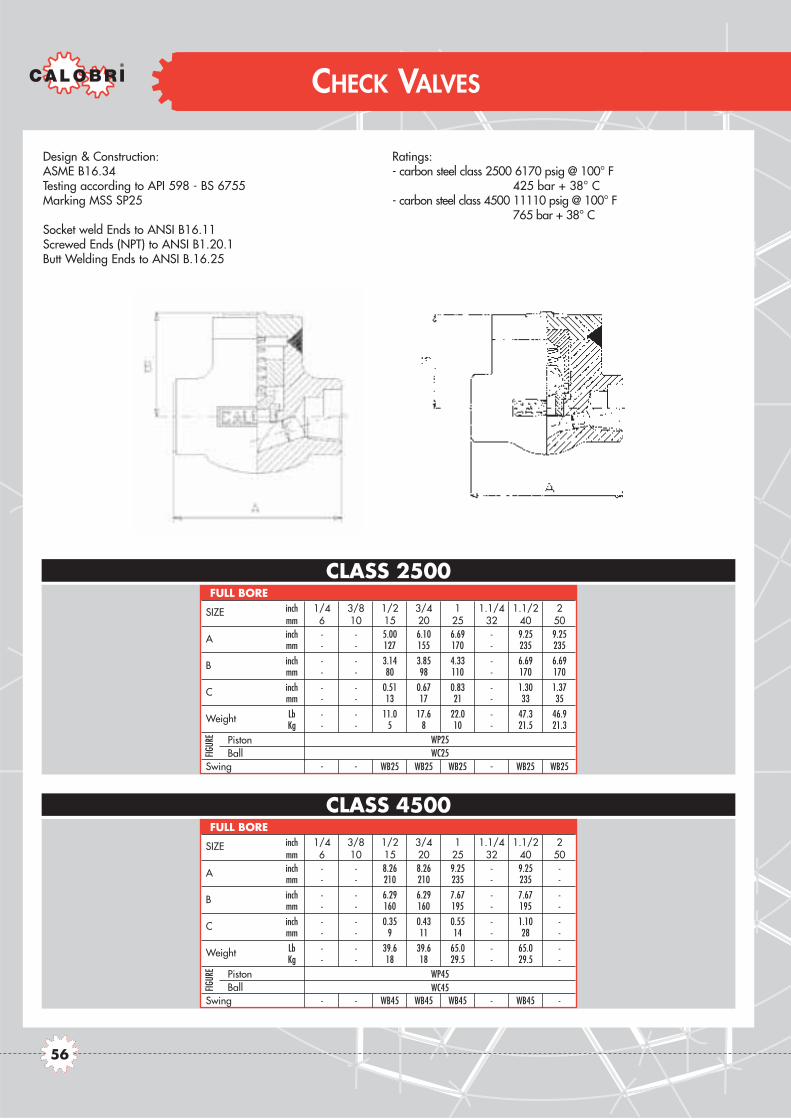
Design & Construction:ASME B16.34Testing according to API 598 - BS 6755Marking MSS SP25
Socket weld Ends to ANSI B16.11Screwed Ends (NPT) to ANSI B1.20.1Butt Welding Ends to ANSI B.16.25
Ratings:- carbon steel class 2500 6170 psig @ 100° F
425 bar + 38° C- carbon steel class 4500 11110 psig @ 100° F
765 bar + 38° C
CLASS 4500
CLASS 2500
CHECK VALVES
SIZE inch 1/4 3/8 1/2 3/4 1 1.1/4 1.1/2 2mm 6 10 15 20 25 32 40 50
A inch - - 5.00 6.10 6.69 - 9.25 9.25mm - - 127 155 170 - 235 235
B inch - - 3.14 3.85 4.33 - 6.69 6.69mm - - 80 98 110 - 170 170
C inch - - 0.51 0.67 0.83 - 1.30 1.37mm - - 13 17 21 - 33 35
Weight Lb - - 11.0 17.6 22.0 - 47.3 46.9Kg - - 5 8 10 - 21.5 21.3
PistonBall
Swing - - WB25 WB25 WB25 - WB25 WB25
FULL BORE
FIGUR
E
SIZE inch 1/4 3/8 1/2 3/4 1 1.1/4 1.1/2 2mm 6 10 15 20 25 32 40 50
A inch - - 8.26 8.26 9.25 - 9.25 -mm - - 210 210 235 - 235 -
B inch - - 6.29 6.29 7.67 - 7.67 -mm - - 160 160 195 - 195 -
C inch - - 0.35 0.43 0.55 - 1.10 -mm - - 9 11 14 - 28 -
Weight Lb - - 39.6 39.6 65.0 - 65.0 -Kg - - 18 18 29.5 - 29.5 -
PistonBall
Swing - - WB45 WB45 WB45 - WB45 -
FULL BORE
FIGUR
E
WP25WC25
WP45WC45
56
CHECK VALVES
Class 800 - 1500 - 2500 - 4500 Welded Bonnet - Full Bore (Y type)

Design & Construction:BS 5352 - ASME B16.34Testing according to API 598 - BS 6755Marking MSS SP25
Socket weld Ends to ANSI B16.11Screwed Ends (NPT) to ANSI B1.20.1Butt Welding Ends to ANSI B.16.25
Ratings:- carbon steel class 800 1975 psig @ 100° F
138 bar + 38° C- carbon steel class 1500 3705 psig @ 100° F
255 bar + 38° C- carbon steel class 2500 6170 psig @ 100° F
425 bar + 38° C- carbon steel class 4500 11110 psig @ 100° F
765 bar + 38° C
CLASS 800
CLASS 1500-1700
CLASS 2500-2700
CHECK VALVES
CLASS 4500
SIZE inch 1/4 3/8 1/2 3/4 1 1.1/4 1.1/2 2mm 6 10 15 20 25 32 40 50
A inch 3.54 3.54 3.54 3.54 5.00 5.00 6.10 7.08mm 90 90 90 90 127 127 155 180
B inch 2.55 2.55 2.55 2.55 3.14 3.74 4.52 5.31mm 65 65 65 65 80 95 115 135
C inch 0.27 0.35 0.51 0.68 0.88 1.16 1.37 1.79mm 7 9 13 17.5 22.5 29.5 35 45.5
WEIGHT lb 2.6 2.6 2.6 3.9 6.6 7.2 12.7 15.4kg 1.2 1.2 1.2 1.2 3 3.3 5.8 7
FIGURE
FULL BORE
SIZE inch 1/4 3/8 1/2 3/4 1 1.1/4 1.1/2 2mm 6 10 15 20 25 32 40 50
A inch 5.00 5.00 5.00 5.00 6.10 6.10 7.08 8.86mm 127 127 127 127 155 155 180 225
B inch 4.52 4.52 4.52 4.72 5.90 5.90 6.30 6.70mm 115 115 115 120 150 150 160 170
C inch 0.27 0.35 0.43 0.59 0.76 1.08 1.24 1.53mm 7 9 11 15 19.5 27.5 31.5 39
WEIGHT lb 7.0 7.0 7.7 7.7 13.7 12.3 22.9 30.8kg 3.2 3.2 3.5 3.5 6.2 5.6 10.4 14
FIGURE
FULL BORE
SIZE inch 1/4 3/8 1/2 3/4 1 1.1/4 1.1/2 2mm 6 10 15 20 25 32 40 50
A inch 3.54 3.54 3.54 5.00 5.00 6.10 6.10 7.08mm 90 90 90 127 127 155 155 180
B inch 2.75 2.75 2.75 3.93 3.93 4.72 4.72 5.51mm 70 70 70 100 100 120 120 140
C inch 0.27 0.35 0.43 0.59 0.76 1.08 1.24 1.53mm 7 9 11 15 19.5 27.5 31.5 39
WEIGHT lb 3.3 3.3 3.3 7.0 7.0 13.2 13.6 20.9kg 1.5 1.5 1.5 3.2 3.2 6 6.2 9.5
FIGURE
FULL BORE
SIZE inch 1/4 3/8 1/2 3/4 1 1.1/4 1.1/2 2mm 6 10 15 20 25 32 40 50
A inch 6.10 6.10 6.10 6.10 6.10 - 8.86 8.86mm 155 155 155 155 155 - 225 225
B inch 4.72 4.72 4.72 4.72 5.70 - 6.30 6.30mm 120 120 120 120 145 - 160 160
C inch 0.27 0.35 0.43 0.43 0.59 - 1.02 1.10mm 7 9 11 11 15 - 26 28
WEIGHT lb 19.1 19.1 19.1 17.6 16.7 - 36.3 35.2kg 8.7 8.7 8.7 8.0 7.6 - 16.5 16
FIGURE
FULL BORE
YP88
YP1515 YP45
YP25
58

57
INTEGRALLY FLANGED VALVES

INTEGRALLY FLANGED VALVES
CLASS DESIGN CONNECTION PORT STANDARD Screw & Yoke ENDS CALOBRI150 Gate Bolted Bonnet Reduced BS5352 Outside Flanged to ASME B16.5 S1F150 Gate Bolted Bonnet Full BS5352 Outside Flanged to ASME B16.5 S11F300 Gate Bolted Bonnet Reduced BS5352 Outside Flanged to ASME B16.5 S3F300 Gate Bolted Bonnet Full BS5352 Outside Flanged to ASME B16.5 S33F600 Gate Bolted Bonnet Reduced BS5352 Outside Flanged to ASME B16.5 S6F600 Gate Bolted Bonnet Full BS5352 Outside Flanged to ASME B16.5 S66F150 Globe Bolted Bonnet Reduced BS5352 Outside Flanged to ASME B16.5 D1F150 Globe Bolted Bonnet Full BS5352 Outside Flanged to ASME B16.5 D11F300 Globe Bolted Bonnet Reduced BS5352 Outside Flanged to ASME B16.5 D3F300 Globe Bolted Bonnet Full BS5352 Outside Flanged to ASME B16.5 D33F600 Globe Bolted Bonnet Reduced BS5352 Outside Flanged to ASME B16.5 D6F600 Globe Bolted Bonnet Full BS5352 Outside Flanged to ASME B16.5 D66F150 Piston Bolted Bonnet Reduced BS5352 Flanged to ASME B16.5 P1F150 Ball Bolted Bonnet Reduced BS5352 Flanged to ASME B16.5 C1F150 Swing Bolted Bonnet Reduced BS5352 Flanged to ASME B16.5 B1F300 Piston Bolted Bonnet Reduced BS5352 Flanged to ASME B16.5 P3F300 Ball Bolted Bonnet Reduced BS5352 Flanged to ASME B16.5 C3F300 Swing Bolted Bonnet Reduced BS5352 Flanged to ASME B16.5 B3F600 Piston Bolted Bonnet Reduced BS5352 Flanged to ASME B16.5 P6F600 Ball Bolted Bonnet Reduced BS5352 Flanged to ASME B16.5 C6F600 Swing Bolted Bonnet Reduced BS5352 Flanged to ASME B16.5 B6F
1500 Gate Ring Joint BB Full BS5352 Outside Flanged to ASME B16.5 RJ S1515F2500 Gate Ring Joint BB Full BS5352 Outside Flanged to ASME B16.5 RJ S25F1500 Globe Ring Joint BB Full BS5352 Outside Flanged to ASME B16.5 RJ D1515F2500 Globe Ring Joint BB Full BS5352 Outside Flanged to ASME B16.5 RJ D25F1500 Piston Ring Joint BB Full BS5352 Flanged to ASME B16.5 RJ P1515F1500 Ball Ring Joint BB Full BS5352 Flanged to ASME B16.5 RJ C1515F1500 Swing Ring Joint BB Full BS5352 Flanged to ASME B16.5 RJ B1515F2500 Piston Ring Joint BB Full BS5352 Flanged to ASME B16.5 RJ P25F2500 Ball Ring Joint BB Full BS5352 Flanged to ASME B16.5 RJ C25F
Note JIS Valve Standards Available on requestDIN Valve Standards Available on request
60
INTEGRALLY FLANGED VALVES
Class 150 to 2500 Bolted Bonnet - Full and Reduced Bore
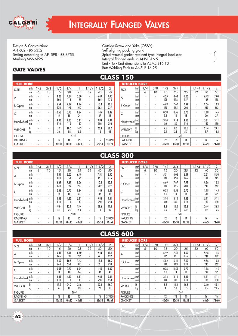
Design & Construction:API 602 - BS 5352Testing according to API 598 - BS 6755Marking MSS SP25
Outside Screw and Yoke (OS&Y)Self aligning packing glandSpiral-wound gasket retained type Integral backseatIntegral flanged ends to ANSI B16.5End - To - End dimensions to ASME B16.10Butt Welding Ends to ANSI B.16.25
CLASS 600
CLASS 300
CLASS 150GATE VALVES
INTEGRALLY FLANGED VALVES
SIZE inch 1/4 3/8 1/2 3/4 1 1.1/4 1.1/2 2mm 6 10 15 20 25 32 40 50
A inch - - 4.25 4.64 5.00 - 6.49 7.00mm - - 108 118 127 - 165 178
B Open inch - - 6.69 7.67 8.26 - 10.3 12.8mm - - 170 195 210 - 262 327
C inch - - 0.55 0.70 0.94 - 1.45 1.89mm - - 14 18 24 - 37 48
Handwheel inch - - 4.33 4.33 5.11 - 9.84 9.84mm - - 110 110 130 - 250 250
WEIGHT lb - - 7.9 10.5 14.3 - 26.4 39.6kg - - 3.6 4.8 6.5 - 12 18
FIGUREPACKING - - T2 T4 T5 - T6 2”#150GASKET - - 40x30 40x30 48x38 - 66x54 81x71
FULL BORE
SIZE inch 1/4 3/8 1/2 3/4 1 1.1/4 1.1/2 2mm 6 10 15 20 25 32 40 50
A inch - - 4.25 4.64 5.00 - 6.49 7.00mm - - 108 118 127 - 165 178
B Open inch - - 6.69 7.67 7.99 - 9.56 10.3mm - - 170 195 203 - 243 262
C inch - - 0.38 0.55 0.70 - 1.18 1.45mm - - 9.6 14 18 - 30 37
Handwheel inch - - 3.14 3.14 4.33 - 5.11 5.11mm - - 80 80 110 - 130 130
WEIGHT lb - - 7.5 8.3 12.5 - 21.4 29.1kg - - 3.4 3.8 5.7 - 9.7 13.2
FIGUREPACKING - - T2 T2 T4 - T6 T6GASKET - - 40x30 40x30 48x38 - 66x54 74x60
REDUCED BORE
SIZE inch 1/4 3/8 1/2 3/4 1 1.1/4 1.1/2 2mm 6 10 15 20 25 32 40 50
A inch - - 5.51 6.02 6.49 - 7.51 8.50mm - - 140 153 165 - 191 216
B Open inch - - 6.69 7.67 8.26 - 10.3 12.8mm - - 170 195 210 - 262 327
C inch - - 0.55 0.70 0.94 - 1.45 1.89mm - - 14 18 24 - 37 48
Handwheel inch - - 4.33 4.33 5.11 - 9.84 9.84mm - - 110 110 130 - 250 250
WEIGHT lb - - 9.0 12.1 15.4 - 28.6 41.8kg - - 4.1 5.5 7.0 - 13 19
FIGUREPACKING - - T2 T3 T5 - T6 2”#150GASKET - - 40x30 40x30 48x38 - 66x54 79x69
FULL BORE
SIZE inch 1/4 3/8 1/2 3/4 1 1.1/4 1.1/2 2mm 6 10 15 20 25 32 40 50
A inch - - 5.51 6.02 6.49 - 7.51 8.50mm - - 140 153 165 - 191 215
B Open inch - - 6.69 7.67 7.99 - 9.56 10.3mm - - 170 195 203 - 243 262
C inch - - 0.38 0.55 0.70 - 1.18 1.45mm - - 9.6 14 18 - 30 37
Handwheel inch - - 3.14 3.14 4.33 - 5.11 5.11mm - - 80 80 110 - 130 130
WEIGHT lb - - 8.6 11.0 13.6 - 26.4 36.3kg - - 3.9 5 6.2 - 12 16.5
FIGUREPACKING - - T2 T2 T4 - T6 T6GASKET - - 40x30 40x30 48x38 - 66x54 74x60
REDUCED BORE
SIZE inch 1/4 3/8 1/2 3/4 1 1.1/4 1.1/2 2mm 6 10 15 20 25 32 40 50
A inch - - 6.49 7.51 8.50 - 9.48 11.5mm - - 165 191 216 - 241 292
B Open inch - - 9.60 10.5 12.2 - 15.4 16.9mm - - 244 268 310 - 391 430
C inch - - 0.55 0.70 0.94 - 1.45 1.89mm - - 14 18 24 - 37 48
Handwheel inch - - 4.33 4.33 5.11 - 9.84 9.84mm - - 110 110 130 - 250 250
WEIGHT lb - - 13.2 24.2 28.6 - 59.4 66.0kg - - 6 11 13 - 27 30
FIGUREPACKING - - T2 T3 T5 - T6 2”#150GASKET - - 40x30 40x30 48x38 - 66x54 79x69
FULL BORE
SIZE inch 1/4 3/8 1/2 3/4 1 1.1/4 1.1/2 2mm 6 10 15 20 25 32 40 50
A inch - - 6.49 7.51 8.50 - 9.48 11.5mm - - 165 191 216 - 241 292
B Open inch - - 5.82 6.41 7.00 - 9.56 10.3mm - - 148 163 178 - 243 262
C inch - - 0.38 0.55 0.70 - 1.18 1.45mm - - 9.6 14 18 - 30 37
Handwheel inch - - 3.14 3.14 4.33 - 5.11 5.11mm - - 80 80 110 - 130 130
WEIGHT lb - - 8.8 11.4 16.5 - 33.0 45.1kg - - 4 5.2 7.5 - 15 20.5
FIGUREPACKING - - T2 T2 T4 - T6 T6GASKET - - 40x30 40x30 48x38 - 66x54 74x60
REDUCED BORE
S11F S1F
S33F S3F
S66F S6F
62

Design & Construction:BS 5352Testing according to API 598 - BS 6755Marking MSS SP25
Outside Screw and Yoke (OS&Y)Self aligning packing glandSpiral-wound gasket retained type Integral backseatIntegral flanged ends to ANSI B16.5End - To - End to ASME B16.10
GLOBE VALVES
INTEGRALLY FLANGED VALVES
CLASS 600
CLASS 300
CLASS 150
SIZE inch 1/4 3/8 1/2 3/4 1 1.1/4 1.1/2 2mm 6 10 15 20 25 32 40 50
A inch - - 4.25 4.64 5.00 - 6.49 7.99mm - - 108 118 127 - 165 203
B Open inch - - 6.69 7.75 8.07 - 9.76 10.1mm - - 170 197 205 - 248 257
C inch - - 0.51 0.68 0.88 - 1.37 1.79mm - - 13 17.5 22.5 - 35 45.5
Handwheel inch - - 3.14 3.14 4.33 - 5.11 7.08mm - - 80 80 110 - 130 180
WEIGHT lb - - 7.5 8.8 12.5 - 22.0 37.4kg - - 3.4 4 5.7 - 10 17.0
FIGUREPACKING - - T2 T3 T5 - T6 T27GASKET - - 40x30 40x30 48x38 - 66x54 74x60
FULL BORE
SIZE inch 1/4 3/8 1/2 3/4 1 1.1/4 1.1/2 2mm 6 10 15 20 25 32 40 50
A inch - - 4.25 4.64 5.00 - 6.49 7.99mm - - 108 118 127 - 165 203
B Open inch - - 6.10 6.88 8.66 - 11.0 13.78mm - - 155 175 220 - 280 350
C inch - - 0.35 0.51 0.69 - 1.16 1.37mm - - 9 13 17.5 - 29.5 35
Handwheel inch - - 3.14 3.14 5.11 - 7.08 7.08mm - - 80 80 130 - 180 180
WEIGHT lb - - 7.04 8.8 15.8 - 32.8 41.8kg - - 3.2 4 7.2 - 14.9 19
FIGUREPACKING - - T2 T3 T5 - T6 T27GASKET - - 40x30 40x30 48x38 - 66x54 74x60
REDUCED BORE
SIZE inch 1/4 3/8 1/2 3/4 1 1.1/4 1.1/2 2mm 6 10 15 20 25 32 40 50
A inch - - 6.02 7.00 7.99 - 9.01 10.5mm - - 153 178 203 - 229 267
B Open inch - - 5.82 6.49 7.08 - 9.76 10.1mm - - 148 165 180 - 248 257
C inch - - 0.51 0.68 0.88 - 1.37 1.79mm - - 13 17.5 22.5 - 35 45.5
Handwheel inch - - 3.14 3.14 4.33 - 5.11 7.08mm - - 80 80 110 - 130 180
WEIGHT lb - - 8.8 11.0 16.1 - 30.8 45.1kg - - 4 5 7.3 - 14 20.5
FIGUREPACKING - - T2 T3 T5 - T6 T27GASKET - - 40x30 40x30 48x38 - 66x54 74x60
FULL BORE
SIZE inch 1/4 3/8 1/2 3/4 1 1.1/4 1.1/2 2mm 6 10 15 20 25 32 40 50
A inch - - 6.02 7.00 7.99 - 9.01 10.5mm - - 153 178 203 - 229 267
B Open inch - - 6.10 6.88 8.66 - 11.0 13.78mm - - 155 175 220 - 280 350
C inch - - 0.35 0.51 0.69 - 1.16 1.37mm - - 9 13 17.5 - 29.5 35
Handwheel inch - - 3.14 3.14 5.11 - 7.08 7.08mm - - 80 80 130 - 180 180
WEIGHT lb - - 9.25 12.5 23.5 - 36.1 46.2kg - - 4.2 5.7 10.7 - 16.4 21
FIGUREPACKING - - T2 T3 T5 - T6 T27GASKET - - 40x30 40x30 48x38 - 66x54 74x60
REDUCED BORE
SIZE inch 1/4 3/8 1/2 3/4 1 1.1/4 1.1/2 2mm 6 10 15 20 25 32 40 50
A inch - - 6.49 7.51 8.50 - 9.48 11.5mm - - 165 191 216 - 241 292
B Open inch - - 5.82 6.49 7.08 - 9.76 10.1mm - - 148 165 180 - 248 257
C inch - - 0.51 0.68 0.88 - 1.37 1.79mm - - 13 17.5 22.5 - 35 45.5
Handwheel inch - - 3.14 3.14 4.33 - 5.11 7.08mm - - 80 80 110 - 130 180
WEIGHT lb - - 9.9 12.1 16.7 - 33.0 46.2kg - - 4.5 5.5 7.6 - 15 21
FIGUREPACKING - - T2 T3 T5 - T6 T27GASKET - - 40x30 40x30 48x38 - 66x54 74x60
FULL BORE
SIZE inch 1/4 3/8 1/2 3/4 1 1.1/4 1.1/2 2mm 6 10 15 20 25 32 40 50
A inch - - 6.49 7.51 8.50 - 9.48 11.5mm - - 165 191 216 - 241 292
B Open inch - - 6.10 6.88 8.66 - 11.0 13.78mm - - 155 175 220 - 280 350
C inch - - 0.35 0.51 0.69 - 1.16 1.37mm - - 9 13 17.5 - 29.5 35
Handwheel inch - - 3.14 3.14 5.11 - 7.08 7.08mm - - 80 80 130 - 180 180
WEIGHT lb - - 10.3 13.2 25.7 - 38.3 50.6kg - - 4.7 6 11.7 - 17.4 23
FIGUREPACKING - - T2 T3 T5 - T6 T27GASKET - - 40x30 40x30 48x38 - 66x54 74x60
REDUCED BORE
D11F D1F
D33F D3F
D66F D6F
63
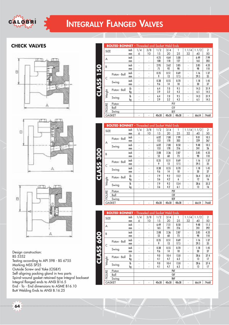
Design construction:BS 5352Testing according to API 598 - BS 6755Marking MSS SP25Outside Screw and Yoke (OS&Y)Self aligning packing gland in two partsSpiral-wound gasket retained type Integral backseatIntegral flanged ends to ANSI B16.5End - To - End dimensions to ASME B16.10Butt Welding Ends to ANSI B.16.25
CLA
SS600
CLA
SS3
00
CLA
SS15
0
CHECK VALVES
INTEGRALLY FLANGED VALVES
SIZE inch 1/4 3/8 1/2 3/4 1 1.1/4 1.1/2 2mm 6 10 15 20 25 32 40 50
A inch - - 4.25 4.64 5.00 - 6.49 7.99mm - - 108 118 127 - 165 203
B inch - - 2.95 3.62 3.85 - 3.85 4.33mm - - 75 92 98 - 98 110
Piston - Ball inch - - 0.35 0.51 0.69 - 1.16 1.37
Cmm - - 9 13 17.5 - 29.5 35
Swing inch - - 0.38 0.55 0.70 - 1.18 1.45mm - - 9.6 14 18 - 30 37
Piston - Ball Lb - - 6.4 7.0 9.5 - 14.3 31.9Kg - - 2.9 3.2 4.3 - 6.5 14.5
Swing lb - - 6.4 7.0 9.5 - 14.3 31.9kg - - 2.9 3.2 4.3 - 6.5 14.5
Piston Ball Swing
GASKET - - 40x30 40x30 48x38 - 66x54 74x60
BOLTED BONNET - Threaded and Socket Weld Ends
Wei
ght
FIG
URE
SIZE inch 1/4 3/8 1/2 3/4 1 1.1/4 1.1/2 2mm 6 10 15 20 25 32 40 50
Piston - Ball inch - - 6.02 7.00 7.99 - 9.01 10.5
Amm - - 153 178 203 - 229 267
Swing inch - - 6.02 7.00 8.50 - 9.48 10.5mm - - 153 178 216 - 241 26
B inch - - 2.08 2.36 2.87 - 3.85 4.33mm - - 53 60 73 - 98 110
Piston - Ball inch - - 0.35 0.51 0.69 - 1.16 1.37
Cmm - - 9 13 17.5 - 29.5 35
Swing inch - - 0.38 0.55 0.70 - 1.18 1.45mm - - 9.6 14 18 - 30 37
Piston - Ball Lb - - 7.9 9.2 13.2 - 26.4 35.2Kg - - 3.6 4.2 6 - 12 16
Swing lb - - 7.9 9.2 13.4 - 28.6 35.2kg - - 3.6 4.2 6.1 - 13 16
Piston Ball Swing
GASKET - - 40x30 40x30 48x38 - 66x54 74x60
BOLTED BONNET - Threaded and Socket Weld Ends
Wei
ght
FIG
URE
SIZE inch 1/4 3/8 1/2 3/4 1 1.1/4 1.1/2 2mm 6 10 15 20 25 32 40 50
A inch - - 6.49 7.51 8.50 - 9.48 11.5mm - - 165 191 216 - 241 292
B inch - - 2.08 2.36 2.87 - 3.85 4.33mm - - 53 60 73 - 98 110
Piston - Ball inch - - 0.35 0.51 0.69 - 1.16 1.37
Cmm - - 9 13 17.5 - 29.5 35
Swing inch - - 0.38 0.55 0.70 - 1.18 1.45mm - - 9.6 14 18 - 30 37
Piston - Ball Lb - - 9.0 10.4 13.8 - 28.6 37.4Kg - - 4.1 4.7 6.3 - 13 17
Swing lb - - 9.0 10.4 13.8 - 28.6 37.4kg - - 4.1 4.7 6.3 - 13 17
PistonBall Swing
GASKET - - 40x30 40x30 48x38 - 66x54 74x60
BOLTED BONNET - Threaded and Socket Weld Ends
Wei
ght
FIG
URE
P1FC1FB1F
P3FC3FB3F
P6FC6FB6F
64

CLASS 1500 CLASS 1500
CLASS 2500 CLASS 2500
INTEGRALLY FLANGED VALVES
SIZE inch 1/4 3/8 1/2 3/4 1 1.1/4 1.1/2 2mm 6 10 15 20 25 32 40 50
A inch - - 8.50 9.01 10.0 - 12.0 14.5mm - - 216 229 254 - 305 368
B Open inch - - 10.2 11.8 11.8 - 15.3 16.5mm - - 260 300 300 - 390 420
C inch - - 0.55 0.70 0.94 - 1.45 1.89mm - - 14 18 24 - 37 48
Handwheel inch - - 4.33 5.11 5.11 - 9.84 11.8mm - - 110 130 130 - 250 300
WEIGHT lb - - 24.2 35.2 41.8 - 77.1 130.0kg - - 11 16 19 - 35 59
FIGUREPACKING - - T5 T6 T6 - T8 T918GASKET - - RJ-13 RJ-16 RJ-17 - RJ-21 RJ-24
FULL BORE
SIZE inch 1/4 3/8 1/2 3/4 1 1.1/4 1.1/2 2mm 6 10 15 20 25 32 40 50
A inch - - 8.50 9.01 10.0 - 12.0 14.5mm - - 216 229 254 - 305 368
B Open inch - - 10.2 11.8 11.8 - 15.3 16.5mm - - 260 300 300 - 390 420
C inch - - 0.51 0.67 0.83 - 1.30 1.48mm - - 13 17 21 - 33 37.5
Handwheel inch - - 4.33 5.11 5.11 - 9.84 11.8mm - - 110 130 130 - 250 300
WEIGHT lb - - 24.2 35.2 42.9 - 74.8 134.3kg - - 11 16 19.5 - 34 61
FIGUREPACKING - - T5 T6 T6 - T8 T918GASKET - - RJ-13 RJ-16 RJ-17 - RJ-21 RJ-23
FULL BORE
SIZE inch 1/4 3/8 1/2 3/4 1 1.1/4 1.1/2 2mm 6 10 15 20 25 32 40 50
A inch - - 10.4 10.7 12.1 - 15.1 17.7mm - - 264 273 308 - 384 451
B Open inch - - 11.9 12.4 14.5 - 17.5 22.2mm - - 304 315 368 - 445 538
C inch - - 0.55 0.70 0.94 - 1.45 1.45mm - - 14 18 24 - 37 37
Handwheel inch - - 5.11 5.11 9.84 - 11.8 11.8mm - - 130 130 250 - 300 300
WEIGHT lb - - 41.8 46.2 88.1 - 136.5 202.6kg - - 19 21 40 - 62 92
FIGUREPACKING - - T25X T6X T8X - T2528X T2528XGASKET - - RJ-13 RJ-16 RJ-17 - RJ-21 RJ-23
FULL BORE
SIZE inch 1/4 3/8 1/2 3/4 1 1.1/4 1.1/2 2mm 6 10 15 20 25 32 40 50
A inch - - 10.4 10.7 12.1 - 15.1 17.7mm - - 264 273 308 - 384 451
B Open inch - - 13.0 13.0 14.5 - 17.1 22.4mm - - 332 332 370 - 435 570
C inch - - 0.43 0.67 0.83 - 1.30 1.48mm - - 11 17 21 - 33 37.5
Handwheel inch - - 5.11 5.11 9.84 - 11.8 11.8mm - - 130 130 250 - 300 300
WEIGHT lb - - 9.9 15.6 16.7 - 37.8 79.5kg - - 4.5 7.1 7.6 - 17.1 36
FIGUREPACKING - - T6X T6X T8X - T2528X T2528XGASKET - - RJ-16 RJ-16 RJ-17 - RJ-21 RJ-23
FULL BORE
GATE VALVES GLOBE VALVES
Design construction:BS 5352ASME B16.34Testing according to API 598 - BS 6755Marking MSS SP25
Outside Screw and Yoke (OS&Y)Self aligning packing gland Oval ring-joint gasket retained type IntegralbackseatIntegral flanged ends to ANSI B16.5End - To - End dimensions to ASME B16.10Butt Welding Ends to ANSI B.16.25Ring - Joint Gasket to ANSI B16.20 - API 6A
RJ S1515F RJ D1515F
RJ S25F RJ D25F
65

Design construction:BS 5352Testing according to API 598 - BS 6755Marking MSS SP25
Outside Screw and Yoke (OS&Y)Self aligning packing glandOval ring-joint gasket retained type Integral backseatIntegral flanged ends to ANSI B16.5End - To - End dimensions to ANSI B16.10Butt Welding Ends to ANSI B.16.25Ring - Joint Gasket to ANSI B16.20 - API 6A
CLASS 2500
CLASS 1500CHECK VALVES
INTEGRALLY FLANGED VALVES
SIZE inch 1/4 3/8 1/2 3/4 1 1.1/4 1.1/2 2mm 6 10 15 20 25 32 40 50
A inch - - 8.50 9.01 10.0 - 12.0 14.5mm - - 216 229 254 - 305 368
B inch - - 5.11 5.51 6.10 - 6.69 7.67mm - - 130 140 155 - 170 195
Piston - Ball inch - - 0.51 0.67 0.83 - 1.30 1.48
Cmm - - 13 17 21 - 33 37.5
Swing inch - - 0.55 0.70 0.94 - 1.45 1.89mm - - 14 18 24 - 37 48
Piston - Ball Lb - - 17.6 30.8 37.5 - 61.6 81.4Kg - - 8 14 17 - 28 37
Swing lb - - 17.1 30.4 36.3 - 59.5 77.1kg - - 7.8 13.8 16.5 - 27 35
Piston Ball Swing
GASKET - - RJ-13 RJ-16 RJ-17 - RJ-21 RJ-23
BOLTED BONNET - Threaded and Socket Weld Ends
Wei
ght
FIG
URE
SIZE inch 1/4 3/8 1/2 3/4 1 1.1/4 1.1/2 2mm 6 10 15 20 25 32 40 50
A inch - - 10.4 10.7 12.1 - 15.1 17.7mm - - 264 273 308 - 384 451
B inch - - 6.10 6.10 6.69 - 9.64 10.23mm - - 155 155 170 - 245 260
C inch - - 0.43 0.67 0.83 - 1.30 1.48mm - - 11 17 21 - 33 37.5
Weight Lb - - 37.5 46.2 61.6 - 127.7 187.2Kg - - 17 21 28 - 58 85
Piston Ball
GASKET - - RJ-16 RJ-16 RJ-17 - RJ-21 RJ-21
BOLTED BONNET - Threaded and Socket Weld Ends
FIGUR
E
RJ P1515FRJ C1515FRJ B1515F
RJ P25FRJ C25F
66

CRYOGENIC VALVES

CRYOGENIC VALVES
Cryogenic Service' refers to service where temperature are below normal atmosfheric temperatures. Definitions vary,but often any temperature below -50°F/ -45°C is considered cryogenic. The bonnet of gate and globe valves is of theextended type with sufficient lenght and a vapour space between body and stuffing box in order to maintain the glandpacking sufficiebtly near ambient temperature to prevent icing of the top works and keep the packing soft and pliablefor optimum sealing characteristics.
CLASS DESIGN CONNECTION PORT STANDARD Screw & Yoke ENDS CALOBRI150 Gate Bolted bonnet-Welded Bon Reduced BS5352 Outside Flanged to ASME B16.5 BT S1F150 Gate Bolted bonnet-Welded Bon Full BS5352 Outside Flanged to ASME B16.5 BT S11F300 Gate Bolted bonnet-Welded Bon Reduced BS5352 Outside Flanged to ASME B16.5 BT S3F300 Gate Bolted bonnet-Welded Bon Full BS5352 Outside Flanged to ASME B16.5 BT S33F600 Gate Bolted bonnet-Welded Bon Reduced BS5352 Outside Flanged to ASME B16.5 BT S6F600 Gate Bolted bonnet-Welded Bon Full BS5352 Outside Flanged to ASME B16.5 BT S66F800 Gate Bolted bonnet-Welded Bon Reduced BS5352 Outside Threaded and Socket Weld Ends BT S8800 Gate Ring Joint BB-Welded Bon Full BS5352 Outside Threaded and Socket Weld Ends BT S88
1500 Gate Bolted bonnet-Welded Bon Reduced BS5352 Outside Threaded and Socket Weld Ends BT S151500 Gate Ring Joint BB-Welded Bon Full BS5352 Outside Threaded and Socket Weld Ends BT S1515150 Globe Bolted bonnet-Welded Bon Reduced BS5352 Outside Flanged to ASME B16.5 BT D1F150 Globe Bolted bonnet-Welded Bon Full BS5352 Outside Flanged to ASME B16.5 BT D11F300 Globe Bolted bonnet-Welded Bon Reduced BS5352 Outside Flanged to ASME B16.5 BT D3F300 Globe Bolted bonnet-Welded Bon Full BS5352 Outside Flanged to ASME B16.5 BT D33F600 Globe Bolted bonnet-Welded Bon Reduced BS5352 Outside Flanged to ASME B16.5 BT D6F600 Globe Bolted bonnet-Welded Bon Full BS5352 Outside Flanged to ASME B16.5 BT D66F800 Globe Bolted bonnet-Welded Bon Reduced BS5352 Outside Threaded and Socket Weld Ends BT D8800 Globe Ring Joint BB-Welded Bon Full BS5352 Outside Threaded and Socket Weld Ends BT D88
1500 Globe Ring Joint BB-Welded Bon Reduced BS5352 Outside Threaded and Socket Weld Ends BT D151500 Globe Ring Joint BB-Welded Bon Full BS5352 Outside Threaded and Socket Weld Ends BT D15151500 Gate Ring Joint BB-Welded Bon Full BS5352 Outside Flanged to ASME B16.5 BT RJ S1515F1500 Globe Ring Joint BB-Welded Bon Full BS5352 Outside Flanged to ASME B16.5 BT RJ D1515F
68

CRYOGENIC VALVES
Class 150 - 300 - 600 - 800 - 1500Bolted Bonnet
Full and Reduced Bore
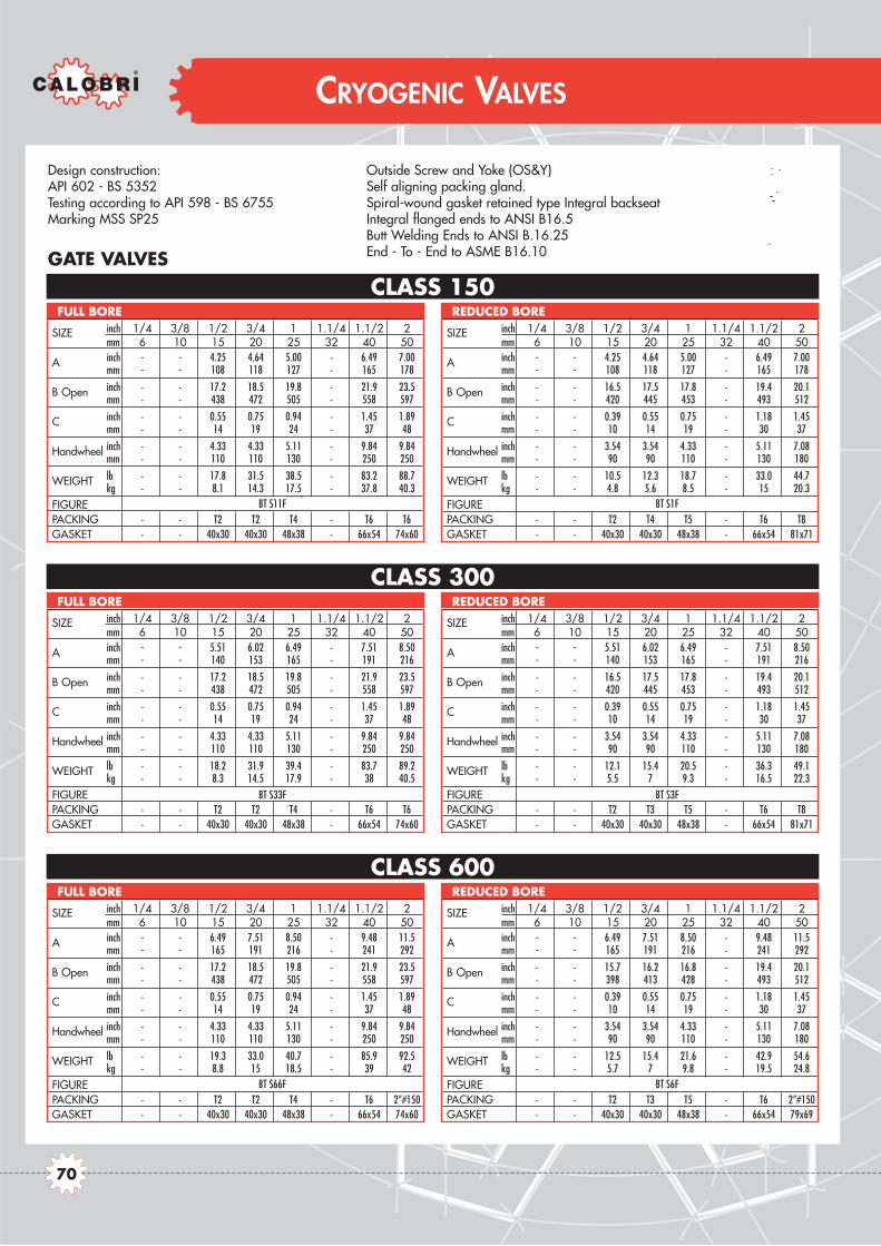
Design construction:API 602 - BS 5352Testing according to API 598 - BS 6755Marking MSS SP25
Outside Screw and Yoke (OS&Y)Self aligning packing gland.Spiral-wound gasket retained type Integral backseatIntegral flanged ends to ANSI B16.5Butt Welding Ends to ANSI B.16.25End - To - End to ASME B16.10
CLASS 600
CLASS 300
CLASS 150
CRYOGENIC VALVES
GATE VALVES
SIZE inch 1/4 3/8 1/2 3/4 1 1.1/4 1.1/2 2mm 6 10 15 20 25 32 40 50
A inch - - 4.25 4.64 5.00 - 6.49 7.00mm - - 108 118 127 - 165 178
B Open inch - - 16.5 17.5 17.8 - 19.4 20.1mm - - 420 445 453 - 493 512
C inch - - 0.39 0.55 0.75 - 1.18 1.45mm - - 10 14 19 - 30 37
Handwheel inch - - 3.54 3.54 4.33 - 5.11 7.08mm - - 90 90 110 - 130 180
WEIGHT lb - - 10.5 12.3 18.7 - 33.0 44.7kg - - 4.8 5.6 8.5 - 15 20.3
FIGUREPACKING - - T2 T4 T5 - T6 T8GASKET - - 40x30 40x30 48x38 - 66x54 81x71
REDUCED BORE
SIZE inch 1/4 3/8 1/2 3/4 1 1.1/4 1.1/2 2mm 6 10 15 20 25 32 40 50
A inch - - 4.25 4.64 5.00 - 6.49 7.00mm - - 108 118 127 - 165 178
B Open inch - - 17.2 18.5 19.8 - 21.9 23.5mm - - 438 472 505 - 558 597
C inch - - 0.55 0.75 0.94 - 1.45 1.89mm - - 14 19 24 - 37 48
Handwheel inch - - 4.33 4.33 5.11 - 9.84 9.84mm - - 110 110 130 - 250 250
WEIGHT lb - - 17.8 31.5 38.5 - 83.2 88.7kg - - 8.1 14.3 17.5 - 37.8 40.3
FIGUREPACKING - - T2 T2 T4 - T6 T6GASKET - - 40x30 40x30 48x38 - 66x54 74x60
FULL BORE
SIZE inch 1/4 3/8 1/2 3/4 1 1.1/4 1.1/2 2mm 6 10 15 20 25 32 40 50
A inch - - 5.51 6.02 6.49 - 7.51 8.50mm - - 140 153 165 - 191 216
B Open inch - - 16.5 17.5 17.8 - 19.4 20.1mm - - 420 445 453 - 493 512
C inch - - 0.39 0.55 0.75 - 1.18 1.45mm - - 10 14 19 - 30 37
Handwheel inch - - 3.54 3.54 4.33 - 5.11 7.08mm - - 90 90 110 - 130 180
WEIGHT lb - - 12.1 15.4 20.5 - 36.3 49.1kg - - 5.5 7 9.3 - 16.5 22.3
FIGUREPACKING - - T2 T3 T5 - T6 T8GASKET - - 40x30 40x30 48x38 - 66x54 81x71
REDUCED BORE
SIZE inch 1/4 3/8 1/2 3/4 1 1.1/4 1.1/2 2mm 6 10 15 20 25 32 40 50
A inch - - 5.51 6.02 6.49 - 7.51 8.50mm - - 140 153 165 - 191 216
B Open inch - - 17.2 18.5 19.8 - 21.9 23.5mm - - 438 472 505 - 558 597
C inch - - 0.55 0.75 0.94 - 1.45 1.89mm - - 14 19 24 - 37 48
Handwheel inch - - 4.33 4.33 5.11 - 9.84 9.84mm - - 110 110 130 - 250 250
WEIGHT lb - - 18.2 31.9 39.4 - 83.7 89.2kg - - 8.3 14.5 17.9 - 38 40.5
FIGUREPACKING - - T2 T2 T4 - T6 T6GASKET - - 40x30 40x30 48x38 - 66x54 74x60
FULL BORE
SIZE inch 1/4 3/8 1/2 3/4 1 1.1/4 1.1/2 2mm 6 10 15 20 25 32 40 50
A inch - - 6.49 7.51 8.50 - 9.48 11.5mm - - 165 191 216 - 241 292
B Open inch - - 15.7 16.2 16.8 - 19.4 20.1mm - - 398 413 428 - 493 512
C inch - - 0.39 0.55 0.75 - 1.18 1.45mm - - 10 14 19 - 30 37
Handwheel inch - - 3.54 3.54 4.33 - 5.11 7.08mm - - 90 90 110 - 130 180
WEIGHT lb - - 12.5 15.4 21.6 - 42.9 54.6kg - - 5.7 7 9.8 - 19.5 24.8
FIGUREPACKING - - T2 T3 T5 - T6 2”#150GASKET - - 40x30 40x30 48x38 - 66x54 79x69
REDUCED BORE
SIZE inch 1/4 3/8 1/2 3/4 1 1.1/4 1.1/2 2mm 6 10 15 20 25 32 40 50
A inch - - 6.49 7.51 8.50 - 9.48 11.5mm - - 165 191 216 - 241 292
B Open inch - - 17.2 18.5 19.8 - 21.9 23.5mm - - 438 472 505 - 558 597
C inch - - 0.55 0.75 0.94 - 1.45 1.89mm - - 14 19 24 - 37 48
Handwheel inch - - 4.33 4.33 5.11 - 9.84 9.84mm - - 110 110 130 - 250 250
WEIGHT lb - - 19.3 33.0 40.7 - 85.9 92.5kg - - 8.8 15 18.5 - 39 42
FIGUREPACKING - - T2 T2 T4 - T6 2”#150GASKET - - 40x30 40x30 48x38 - 66x54 74x60
FULL BORE
GATE VALVES
BT S11F BT S1F
BT S33F BT S3F
BT S66F BT S6F
70
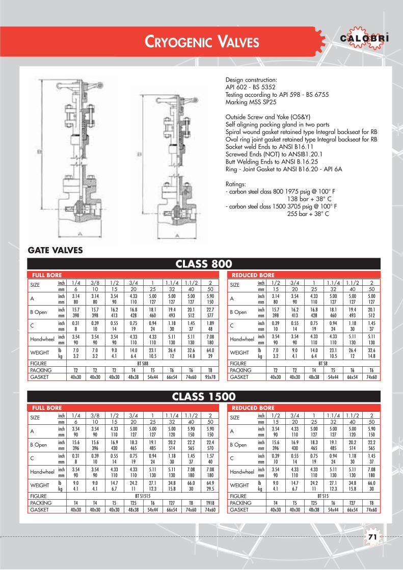
Design construction:API 602 - BS 5352Testing according to API 598 - BS 6755Marking MSS SP25
Outside Screw and Yoke (OS&Y)Self aligning packing gland in two partsSpiral wound gasket retained type Integral backseat for RBOval ring joint gasket retained type Integral backseat for RBSocket weld Ends to ANSI B16.11Screwed Ends (NOT) to ANSIB1.20.1Butt Welding Ends to ANSI B.16.25Ring - Joint Gasket to ANSI B16.20 - API 6A
Ratings:- carbon steel class 800 1975 psig @ 100° F
138 bar + 38° C- carbon steel class 1500 3705 psig @ 100° F
255 bar + 38° C
CRYOGENIC VALVES
CLASS 1500
CLASS 800GATE VALVES
SIZE inch 1/4 3/8 1/2 3/4 1 1.1/4 1.1/2 2mm 6 10 15 20 25 32 40 50
A inch 3.14 3.14 3.54 4.33 5.00 5.00 5.00 5.90mm 80 80 90 110 127 127 127 150
B Open inch 15.7 15.7 16.2 16.8 18.1 19.4 20.1 22.7mm 398 398 413 428 460 493 512 577
C inch 0.31 0.39 0.55 0.75 0.94 1.18 1.45 1.89mm 8 10 14 19 24 30 37 48
Handwheel inch 3.54 3.54 3.54 4.33 4.33 5.11 5.11 7.08mm 90 90 90 110 110 130 130 180
WEIGHT lb 7.0 7.0 9.0 14.0 23.1 26.4 32.6 64.0kg 3.2 3.2 4.1 6.4 10.5 12 14.8 29
FIGUREPACKING T2 T2 T2 T4 T5 T6 T6 T8GASKET 40x30 40x30 40x30 48x38 54x44 66x54 74x60 95x78
FULL BORE
SIZE inch 1/2 3/4 1 1.1/4 1.1/2 2mm 15 20 25 32 40 50
A inch 3.14 3.54 4.33 5.00 5.00 5.00mm 80 90 110 127 127 127
B Open inch 15.7 16.2 16.8 18.1 19.4 20.1mm 398 413 428 460 493 512
C inch 0.39 0.55 0.75 0.94 1.18 1.45mm 10 14 19 24 30 37
Handwheel inch 3.54 3.54 4.33 4.33 5.11 5.11mm 90 90 110 110 130 130
WEIGHT lb 7.0 9.0 14.0 23.1 26.4 32.6kg 3.2 4.1 6.4 10.5 12 14.8
FIGUREPACKING T2 T2 T4 T5 T6 T6GASKET 40x30 40x30 48x38 54x44 66x54 74x60
REDUCED BORE
SIZE inch 1/4 3/8 1/2 3/4 1 1.1/4 1.1/2 2mm 6 10 15 20 25 32 40 50
A inch 3.54 3.54 4.33 5.00 5.00 5.00 5.90 5.90mm 90 90 110 127 127 120 150 150
B Open inch 15.6 15.6 16.9 18.3 19.1 20.2 22.2 22.4mm 396 396 430 465 485 514 565 570
C inch 0.31 0.39 0.55 0.75 0.94 1.18 1.45 1.57mm 8 10 14 19 24 30 37 40
Handwheel inch 3.54 3.54 4.33 4.33 5.11 5.11 7.08 7.08mm 90 90 110 110 130 130 180 180
WEIGHT lb 9.0 9.0 14.7 24.2 27.1 34.8 66.0 64.9kg 4.1 4.1 6.7 11 12.3 15.8 30 29.5
FIGUREPACKING T4 T4 T5 T25 T6 T27 T8 T918GASKET 40x30 40x30 40x30 48x38 54x44 66x54 74x60 74x60
FULL BORE
SIZE inch 1/2 3/4 1 1.1/4 1.1/2 2mm 15 20 25 32 40 50
A inch 3.54 4.33 5.00 5.00 5.00 5.90mm 90 110 127 127 120 150
B Open inch 15.6 16.9 18.3 19.1 20.2 22.2mm 396 430 465 485 514 565
C inch 0.39 0.55 0.75 0.94 1.18 1.45mm 10 14 19 24 30 37
Handwheel inch 3.54 4.33 4.33 5.11 5.11 7.08mm 90 110 110 130 130 180
WEIGHT lb 9.0 14.7 24.2 27.1 34.8 66.0kg 4.1 6.7 11 12.3 15.8 30
FIGUREPACKING T4 T5 T25 T6 T27 T8GASKET 40x30 40x30 48x38 54x44 66x54 74x60
REDUCED BORE
BT S88 BT S8
BT S1515 BT S15
71

Design construction:BS 5352Testing according to API 598 - BS 6755Marking MSS SP25
Outside Screw and Yoke (OS&Y)Self aligning packing gland Spiral-wound gasket retained type Integral backseatButt Welding Ends to ANSI B.16.25Integral flanged ends to ANSI B16.5End - To - End dimensions to ASME B16.10
CLASS 600
CLASS 300
CLASS 150GLOBE VALVES
CRYOGENIC VALVES
SIZE inch 1/4 3/8 1/2 3/4 1 1.1/4 1.1/2 2mm 6 10 15 20 25 32 40 50
A inch - - 4.25 4.64 5.00 - 6.49 7.99mm - - 108 118 127 - 165 203
B Open inch - - 16.5 17.6 17.9 - 19.6 19.9mm - - 420 447 455 - 498 507
C inch - - 0.35 0.51 0.69 - 1.16 1.37mm - - 9 13 17.5 - 29.5 35
Handwheel inch - - 3.54 3.54 4.33 - 5.11 7.08mm - - 90 90 110 - 130 180
WEIGHT lb - - 11 12.7 18.9 - 30.4 53.5kg - - 5 5.8 8.6 - 13.8 24.3
FIGUREPACKING - - T2 T3 T5 - T6 T27GASKET - - 40x30 40x30 48x38 - 66x54 74x60
REDUCED BORE
SIZE inch 1/4 3/8 1/2 3/4 1 1.1/4 1.1/2 2mm 6 10 15 20 25 32 40 50
A inch - - 4.25 4.64 5.00 - 6.49 7.99mm - - 108 118 127 - 165 203
B Open inch - - 19.4 20.6 21.4 - 25.9 27.1mm - - 495 523 545 - 660 690
C inch - - 0.51 0.69 0.89 - 1.37 1.79mm - - 13 17.5 22.5 - 35 45.5
Handwheel inch - - 3.54 4.33 5.11 - 9.84 9.84mm - - 90 110 130 - 250 250
WEIGHT lb - - 17.8 31.5 38.5 - 83.2 89.2kg - - 8.1 14.3 17.5 - 37.8 40.5
FIGUREPACKING - - T2 T3 T5 - T6 T27GASKET - - 40x30 40x30 48x38 - 66x54 74x60
FULL BORE
SIZE inch 1/4 3/8 1/2 3/4 1 1.1/4 1.1/2 2mm 6 10 15 20 25 32 40 50
A inch - - 6.02 7.00 7.99 - 9.01 10.5mm - - 153 178 203 - 229 267
B Open inch - - 15.7 16.3 16.9 - 19.6 19.9mm - - 398 415 430 - 498 507
C inch - - 0.35 0.51 0.69 - 1.16 1.37mm - - 9 13 17.5 - 29.5 35
Handwheel inch - - 3.54 3.54 4.33 - 5.11 7.08mm - - 90 90 110 - 130 180
WEIGHT lb - - 12.7 14.9 22.6 - 42.5 56.8kg - - 5.8 6.8 10.3 - 19.3 25.8
FIGUREPACKING - - T2 T3 T5 - T6 T27GASKET - - 40x30 40x30 48x38 - 66x54 74x60
REDUCED BORE
SIZE inch 1/4 3/8 1/2 3/4 1 1.1/4 1.1/2 2mm 6 10 15 20 25 32 40 50
A inch - - 6.02 7.00 7.99 - 9.01 10.5mm - - 153 178 203 - 229 267
B Open inch - - 19.4 20.6 21.4 - 25.9 27.1mm - - 495 523 545 - 660 690
C inch - - 0.51 0.69 0.89 - 1.37 1.79mm - - 13 17.5 22.5 - 35 45.5
Handwheel inch - - 3.54 4.33 5.11 - 9.84 9.84mm - - 90 110 130 - 250 250
WEIGHT lb - - 18.9 32.6 40.3 - 84.8 90.3kg - - 8.6 14.8 18.3 - 38.5 41
FIGUREPACKING - - T2 T3 T5 - T6 T27GASKET - - 40x30 40x30 48x38 - 66x54 74x60
FULL BORE
SIZE inch 1/4 3/8 1/2 3/4 1 1.1/4 1.1/2 2mm 6 10 15 20 25 32 40 50
A inch - - 6.49 7.51 8.50 - 9.48 11.5mm - - 165 191 216 - 241 292
B Open inch - - 15.7 16.3 16.9 - 19.6 19.9mm - - 398 415 430 - 498 507
C inch - - 0.35 0.51 0.69 - 1.16 1.37mm - - 9 13 17.5 - 29.5 35
Handwheel inch - - 3.54 3.54 4.33 - 5.11 7.08mm - - 90 90 110 - 130 180
WEIGHT lb - - 13.8 16 23.3 - 44.7 59kg - - 6.3 7.3 10.6 - 20.3 26.8
FIGUREPACKING - - T2 T3 T5 - T6 T27GASKET - - 40x30 40x30 48x38 - 66x54 74x60
REDUCED BORE
SIZE inch 1/4 3/8 1/2 3/4 1 1.1/4 1.1/2 2mm 6 10 15 20 25 32 40 50
A inch - - 6.49 7.51 8.50 - 9.48 11.5mm - - 165 191 216 - 241 292
B Open inch - - 19.4 20.6 21.4 - 25.9 27.1mm - - 495 523 545 - 660 690
C inch - - 0.51 0.69 0.89 - 1.37 1.79mm - - 13 17.5 22.5 - 35 45.5
Handwheel inch - - 3.54 4.33 5.11 - 9.84 9.84mm - - 90 110 130 - 250 250
WEIGHT lb - - 19.3 33.0 40.7 - 85.9 92.5kg - - 8.8 15 18.5 - 39 42
FIGUREPACKING - - T2 T3 T5 - T6 T27GASKET - - 40x30 40x30 48x38 - 66x54 74x60
FULL BORE
BT D11F BT D1F
BT D33F BT D3F
BT D66F BT D6F
72
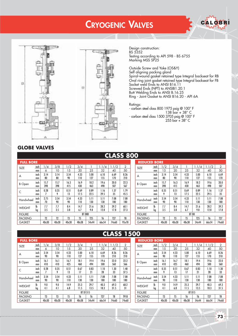
Design construction:BS 5352Testing according to API 598 - BS 6755Marking MSS SP25
Outside Screw and Yoke (OS&Y)Self aligning packing glandSpiral-wound gasket retained type Integral backseat for RBOval ring joint gasket retained type Integral backseat for FBSocket weld Ends to ANSI B16.11Screwed Ends (NPT) to ANSIB1.20.1Butt Welding Ends to ANSI B.16.25Ring - Joint Gasket to ANSI B16.20 - API 6A
Ratings:- carbon steel class 800 1975 psig @ 100° F
138 bar + 38° C- carbon steel class 1500 3705 psig @ 100° F
255 bar + 38° C
CRYOGENIC VALVES
CLASS 1500
CLASS 800GLOBE VALVES
SIZE inch 1/4 3/8 1/2 3/4 1 1.1/4 1.1/2 2mm 6 10 15 20 25 32 40 50
A inch 3.14 3.14 3.54 4.33 5.00 6.10 6.69 8.26mm 80 80 90 110 127 155 170 210
B Open inch 15.7 15.7 16.3 16.9 18.2 19.6 20.0 22.3mm 398 398 415 430 463 498 507 567
C inch 0.28 0.35 0.51 0.69 0.89 1.16 1.37 1.79mm 7 9 13 17.5 22.5 29.5 35 45.5
Handwheel inch 2.75 3.54 3.54 4.33 5.11 5.11 7.08 7.08mm 70 90 90 110 130 130 180 180
WEIGHT lb 7.7 7.7 8.4 14.7 21.6 28.2 39.2 60.1kg 3.5 3.5 3.8 6.7 9.8 12.8 17.8 27.3
FIGUREPACKING T2 T2 T3 T5 T25 T6 T27 T8GASKET 40x30 40x30 40x30 48x38 54x44 66x54 74x60 95x78
FULL BORE
SIZE inch 1/2 3/4 1 1.1/4 1.1/2 2mm 15 20 25 32 40 50
A inch 3.14 3.54 4.33 5.00 6.10 6.69mm 80 90 110 127 155 170
B Open inch 15.7 16.3 16.9 18.2 19.6 20.0mm 398 415 430 463 498 507
C inch 0.35 0.51 0.69 0.89 1.16 1.37mm 9 13 17.5 22.5 29.5 35
Handwheel inch 3.54 3.54 4.33 5.11 5.11 7.08mm 90 90 110 130 130 180
WEIGHT lb 7.7 8.4 14.7 21.6 28.2 39.2kg 3.5 3.8 6.7 9.8 12.8 17.8
FIGUREPACKING T2 T3 T5 T25 T6 T27GASKET 40x30 40x30 48x38 54x44 66x54 74x60
REDUCED BORE
SIZE inch 1/4 3/8 1/2 3/4 1 1.1/4 1.1/2 2mm 6 10 15 20 25 32 40 50
A inch 3.54 3.54 4.33 5.00 6.10 6.69 8.26 8.26mm 90 90 110 127 155 170 210 210
B Open inch 16.1 16.1 16.7 18.1 19.4 19.6 22.0 22.2mm 410 410 425 460 494 500 560 566
C inch 0.28 0.35 0.51 0.67 0.83 1.10 1.30 1.48mm 7 9 13 17 21 28 33 37.5
Handwheel inch 3.54 3.54 4.33 5.11 5.11 7.08 7.08 7.08mm 90 90 110 130 130 180 180 180
WEIGHT lb 9.0 9.0 14.9 25.3 29.7 40.3 69.3 68.2kg 4.1 4.1 6.8 11.5 13.5 18.3 31.5 31
FIGUREPACKING T3 T3 T5 T6 T6 T27 T8 T918GASKET 40x30 40x30 40x30 48x38 54x44 66x54 74x60 74x60
FULL BORE
SIZE inch 1/2 3/4 1 1.1/4 1.1/2 2mm 15 20 25 32 40 50
A inch 3.54 4.33 5.00 6.10 6.69 8.26mm 90 110 127 155 170 210
B Open inch 16.1 16.7 18.1 19.4 19.6 22.0mm 410 425 460 494 500 560
C inch 0.35 0.51 0.67 0.83 1.10 1.30mm 9 13 17 21 28 33
Handwheel inch 3.54 4.33 5.11 5.11 7.08 7.08mm 90 110 130 130 180 180
WEIGHT lb 9.0 14.9 25.3 29.7 40.3 69.3kg 4.1 6.8 11.5 13.5 18.3 31.5
FIGUREPACKING T3 T5 T6 T6 T27 T8GASKET 40x30 40x30 48x38 54x44 66x54 74x60
REDUCED BORE
BT D88 BT D8
BT D1515 BT D15
73
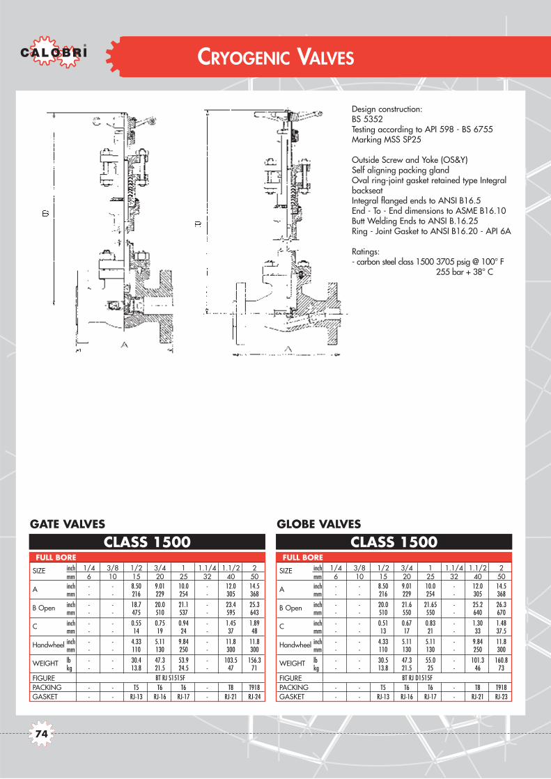
Design construction:BS 5352Testing according to API 598 - BS 6755Marking MSS SP25
Outside Screw and Yoke (OS&Y)Self aligning packing glandOval ring-joint gasket retained type IntegralbackseatIntegral flanged ends to ANSI B16.5End - To - End dimensions to ASME B16.10Butt Welding Ends to ANSI B.16.25Ring - Joint Gasket to ANSI B16.20 - API 6A
Ratings:- carbon steel class 1500 3705 psig @ 100° F
255 bar + 38° C
CLASS 1500 CLASS 1500GATE VALVES GLOBE VALVES
CRYOGENIC VALVES
SIZE inch 1/4 3/8 1/2 3/4 1 1.1/4 1.1/2 2mm 6 10 15 20 25 32 40 50
A inch - - 8.50 9.01 10.0 - 12.0 14.5mm - - 216 229 254 - 305 368
B Open inch - - 18.7 20.0 21.1 - 23.4 25.3mm - - 475 510 537 - 595 643
C inch - - 0.55 0.75 0.94 - 1.45 1.89mm - - 14 19 24 - 37 48
Handwheel inch - - 4.33 5.11 9.84 - 11.8 11.8mm - - 110 130 250 - 300 300
WEIGHT lb - - 30.4 47.3 53.9 - 103.5 156.3kg - - 13.8 21.5 24.5 - 47 71
FIGUREPACKING - - T5 T6 T6 - T8 T918GASKET - - RJ-13 RJ-16 RJ-17 - RJ-21 RJ-24
FULL BORE
SIZE inch 1/4 3/8 1/2 3/4 1 1.1/4 1.1/2 2mm 6 10 15 20 25 32 40 50
A inch - - 8.50 9.01 10.0 - 12.0 14.5mm - - 216 229 254 - 305 368
B Open inch - - 20.0 21.6 21.65 - 25.2 26.3mm - - 510 550 550 - 640 670
C inch - - 0.51 0.67 0.83 - 1.30 1.48mm - - 13 17 21 - 33 37.5
Handwheel inch - - 4.33 5.11 5.11 - 9.84 11.8mm - - 110 130 130 - 250 300
WEIGHT lb - - 30.5 47.3 55.0 - 101.3 160.8kg - - 13.8 21.5 25 - 46 73
FIGUREPACKING - - T5 T6 T6 - T8 T918GASKET - - RJ-13 RJ-16 RJ-17 - RJ-21 RJ-23
FULL BORE
BT RJ S1515F BT RJ D1515F
74

73
BELLOWS SEALED VALVES
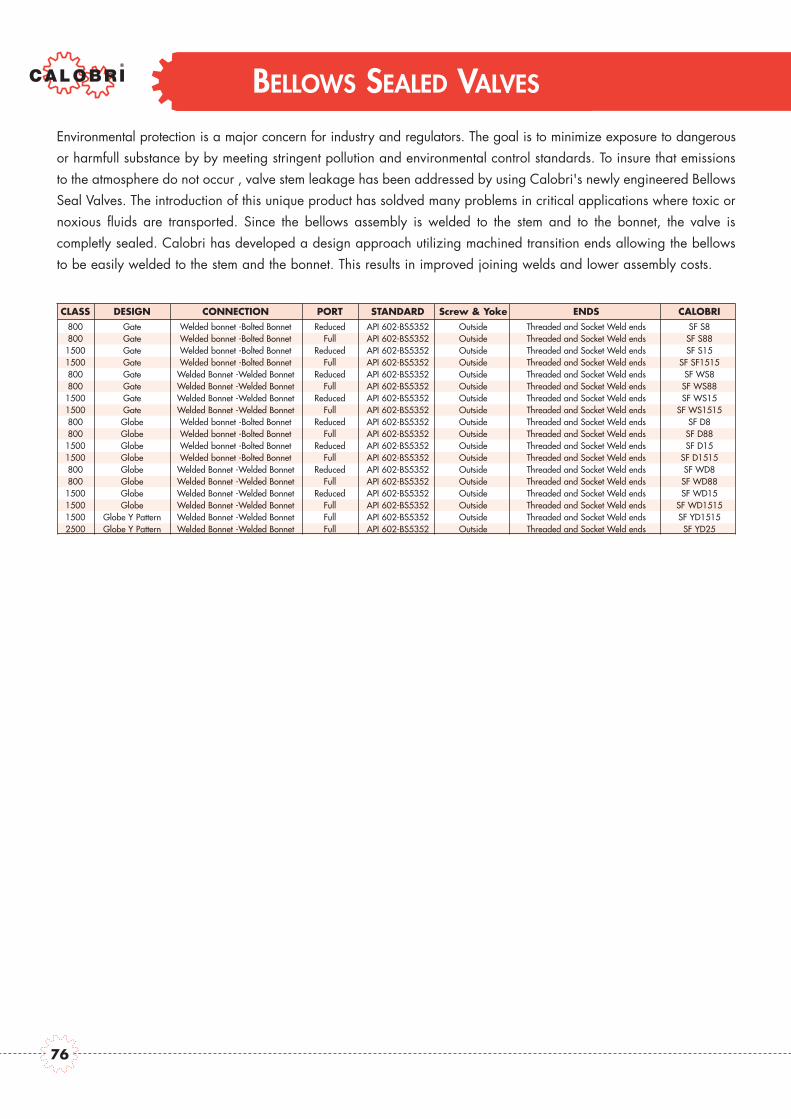
BELLOWS SEALED VALVES
Environmental protection is a major concern for industry and regulators. The goal is to minimize exposure to dangerousor harmfull substance by by meeting stringent pollution and environmental control standards. To insure that emissionsto the atmosphere do not occur , valve stem leakage has been addressed by using Calobri's newly engineered BellowsSeal Valves. The introduction of this unique product has soldved many problems in critical applications where toxic ornoxious fluids are transported. Since the bellows assembly is welded to the stem and to the bonnet, the valve is completly sealed. Calobri has developed a design approach utilizing machined transition ends allowing the bellowsto be easily welded to the stem and the bonnet. This results in improved joining welds and lower assembly costs.
CLASS DESIGN CONNECTION PORT STANDARD Screw & Yoke ENDS CALOBRI800 Gate Welded bonnet -Bolted Bonnet Reduced API 602-BS5352 Outside Threaded and Socket Weld ends SF S8800 Gate Welded bonnet -Bolted Bonnet Full API 602-BS5352 Outside Threaded and Socket Weld ends SF S88
1500 Gate Welded bonnet -Bolted Bonnet Reduced API 602-BS5352 Outside Threaded and Socket Weld ends SF S151500 Gate Welded bonnet -Bolted Bonnet Full API 602-BS5352 Outside Threaded and Socket Weld ends SF SF1515800 Gate Welded Bonnet -Welded Bonnet Reduced API 602-BS5352 Outside Threaded and Socket Weld ends SF WS8800 Gate Welded Bonnet -Welded Bonnet Full API 602-BS5352 Outside Threaded and Socket Weld ends SF WS88
1500 Gate Welded Bonnet -Welded Bonnet Reduced API 602-BS5352 Outside Threaded and Socket Weld ends SF WS151500 Gate Welded Bonnet -Welded Bonnet Full API 602-BS5352 Outside Threaded and Socket Weld ends SF WS1515800 Globe Welded bonnet -Bolted Bonnet Reduced API 602-BS5352 Outside Threaded and Socket Weld ends SF D8800 Globe Welded bonnet -Bolted Bonnet Full API 602-BS5352 Outside Threaded and Socket Weld ends SF D88
1500 Globe Welded bonnet -Bolted Bonnet Reduced API 602-BS5352 Outside Threaded and Socket Weld ends SF D151500 Globe Welded bonnet -Bolted Bonnet Full API 602-BS5352 Outside Threaded and Socket Weld ends SF D1515800 Globe Welded Bonnet -Welded Bonnet Reduced API 602-BS5352 Outside Threaded and Socket Weld ends SF WD8800 Globe Welded Bonnet -Welded Bonnet Full API 602-BS5352 Outside Threaded and Socket Weld ends SF WD88
1500 Globe Welded Bonnet -Welded Bonnet Reduced API 602-BS5352 Outside Threaded and Socket Weld ends SF WD151500 Globe Welded Bonnet -Welded Bonnet Full API 602-BS5352 Outside Threaded and Socket Weld ends SF WD15151500 Globe Y Pattern Welded Bonnet -Welded Bonnet Full API 602-BS5352 Outside Threaded and Socket Weld ends SF YD15152500 Globe Y Pattern Welded Bonnet -Welded Bonnet Full API 602-BS5352 Outside Threaded and Socket Weld ends SF YD25
76

BELLOWS SEALED VALVES
Class 800 to 2700 Bolted Bonnet - Welded Bonnet
Full and Reduced Bore

Design construction:API 602 - BS 5352Testing according to API 598 - BS 6755Marking MSS SP25
Outside Screw and Yoke (OS&Y)Self aligning packing glandSpiral-wound gasket retained type Integral backseatSocket weld Ends to ANSI B16.11Screwed Ends (NPT) to ANSIB1.20.1Butt Welding Ends to ANSI B.16.25
CLASS 1500
CLASS 800GATE VALVES
BELLOWS SEALED VALVES
SIZE inch 1/4 3/8 1/2 3/4 1 1.1/4 1.1/2 2mm 6 10 15 20 25 32 40 50
A inch 3.14 3.14 3.54 4.33 5.00 5.00 5.00 8.26mm 80 80 90 110 127 127 127 210
B Open inch 10.3 10.3 11.6 13.9 16.2 18.5 20.9 25.6mm 262 262 296 353 412 470 531 650
C inch 0.31 0.38 0.55 0.70 0.94 1.18 1.45 1.89mm 8 9.6 14 18 24 30 37 48
Handwheel inch 3.14 3.14 3.14 4.33 5.11 5.11 7.08 7.08mm 80 80 80 110 130 130 180 180
Bolted B. Lb 4.8 4.8 6.6 9.3 17.4 19.8 32.6 73.8Kg 2.2 2.2 3 4.2 7.9 9 14.8 33.5
Welded B. Lb 4.8 4.8 6.6 9.3 17.4 19.8 32.6 73.8Kg 2.2 2.2 3 4.2 7.9 9 14.8 33.5
Bolted B.Welded B.
PACKING T2 T2 T2 T4 T5 T6 T6 T8GASKET 40x30 40x30 40x30 48x38 54x44 66x54 74x60 95x78
FULL BORE
FIGUR
EW
eigh
t
SIZE inch 1/2 3/4 1 1.1/4 1.1/2 2mm 15 20 25 32 40 50
A inch 3.14 3.54 4.33 5.00 5.00 5.00mm 80 90 110 127 127 127
B Open inch 10.3 11.6 13.9 16.2 16.2 20.9mm 262 296 353 412 470 531
C inch 0.38 0.55 0.70 0.94 1.18 1.45mm 9.6 14 18 24 30 37
Handwheel inch 3.14 3.14 4.33 5.11 5.11 7.08mm 80 80 110 130 130 180
Bolted B. Lb 4.8 4.8 9.3 17.4 19.8 32.6Kg 2.2 3 4.2 7.9 9 14.8
Welded B. Lb 4.8 4.8 9.3 17.4 19.8 32.6Kg 2.2 3 4.2 7.9 9 14.8
Bolted B.Welded B.
PACKING T2 T2 T4 T5 T6 T6GASKET 40x30 40x30 48x38 54x44 66x54 74x60
REDUCED BORE
FIGUR
EW
eigh
t
SIZE inch 1/4 3/8 1/2 3/4 1 1.1/4 1.1/2 2mm 6 10 15 20 25 32 40 50
A inch 3.54 3.54 4.33 5.00 5.00 5.00 8.26 8.26mm 90 90 110 127 127 127 210 210
B Open inch 12.9 13.0 14.6 18.7 20.1 23.0 25.6 32.0mm 328 331 372 475 510 586 650 815
C inch 0.31 0.38 0.55 0.70 0.94 1.18 1.45 1.57mm 8 9.6 14 18 24 30 37 40
Handwheel inch 5.11 5.11 5.11 5.11 7.08 7.08 9.84 9.84mm 130 130 130 130 180 180 250 250
Bolted B. Lb 8.1 8.1 11.6 17.6 23.1 37.4 67.2 79.3Kg 3.7 3.7 5.3 8 10.5 17 30.5 36
Welded B. Lb 8.1 8.1 11.6 17.6 23.1 37.4 67.2 79.3Kg 3.7 3.7 5.3 8 10.5 17 30.5 36
Bolted B.Welded B.
PACKING T4 T4 T5 T25 T6 T27 T8 T918GASKET 40x30 40x30 40x30 48x38 54x44 66x54 74x60 74x60
FULL BORE
FIGUR
EW
eigh
t
SIZE inch 1/2 3/4 1 1.1/4 1.1/2 2mm 15 20 25 32 40 50
A inch 3.54 4.33 5.00 5.00 5.00 8.26mm 90 110 127 127 127 210
B Open inch 12.9 13.0 14.6 18.7 20.1 23.0mm 328 331 372 475 510 586
C inch 0.38 0.55 0.70 0.94 1.18 1.45mm 9.6 14 18 24 30 37
Handwheel inch 5.11 5.11 5.11 7.08 7.08 9.84mm 130 130 130 180 180 250
Bolted B. Lb 8.1 11.6 17.6 23.1 37.4 67.2Kg 3.7 5.3 8 10.5 17 30.5
Welded B. Lb 8.1 11.6 17.6 23.1 37.4 67.2Kg 3.7 5.3 8 10.5 17 30.5
Bolted B.Welded B.
PACKING T4 T5 T25 T6 T27 T8GASKET 40x30 40x30 48x38 54x44 66x54 74x60
REDUCED BORE
FIGUR
EW
eigh
t
SF S88SF WS88
SF S8SF WS8
SF S1515SF WS1515
SF S15SF WS15
78

Design construction:API 602 - BS 5352Testing according to API 598 - BS 6755Marking MSS SP25
Outside Screw and Yoke (OS&Y)Self aligning packing glandSpiral-wound gasket retained type Integral backseatSocket weld Ends to ANSI B16.11Screwed Ends (NPT) to ANSIB1.20.1Butt Welding Ends to ANSI B.16.25
CLASS 1500
CLASS 800
BELLOWS SEALED VALVES
SIZE inch 1/4 3/8 1/2 3/4 1 1.1/4 1.1/2 2mm 6 10 15 20 25 32 40 50
A inch 3.14 3.14 3.54 4.33 5.00 6.10 6.69 8.26mm 80 80 90 110 127 155 170 210
B Open inch 9.60 9.60 10.9 12.2 14.4 16.8 18.2 23.2mm 244 244 276 311 366 428 462 590
C inch 0.28 0.35 0.51 0.69 0.88 1.16 1.37 1.79mm 7 9 13 17.5 22.5 29.5 35 45.5
Handwheel inch 3.14 3.14 3.14 4.33 5.11 5.11 7.08 7.08mm 80 80 80 110 130 130 180 180
Bolted B. Lb 5.1 5.1 6.6 10.3 17.4 26.0 38.1 76.6Kg 2.3 2.3 3.0 4.7 7.9 11.8 17.3 34.5
Welded B. Lb 5.1 5.1 6.6 10.3 17.4 26.0 38.1 76.6Kg 2.3 2.3 3.0 4.7 7.9 11.8 17.3 34.5
Bolted B.Welded B.
PACKING T2 T2 T3 T5 T25 T6 T27 T8GASKET 40x30 40x30 40x30 48x38 54x44 66x54 74x60 95x78
FULL BORE
FIGUR
EW
eigh
t
SIZE inch 1/2 3/4 1 1.1/4 1.1/2 2mm 15 20 25 32 40 50
A inch 3.14 3.54 4.33 5.00 6.10 6.69mm 80 90 110 127 155 170
B Open inch 9.60 10.9 12.2 14.4 16.8 18.2mm 244 276 311 366 428 462
C inch 0.35 0.51 0.69 0.88 1.16 1.37mm 9 13 17.5 22.5 29.5 35
Handwheel inch 3.14 3.14 4.33 5.11 5.11 7.08mm 80 80 110 130 130 180
Bolted B. Lb 5.1 6.6 10.3 17.4 26.0 38.1Kg 2.3 3.0 4.7 7.9 11.8 17.3
Welded B. Lb 5.1 6.6 10.3 17.4 26.0 38.1Kg 2.3 3.0 4.7 7.9 11.8 17.3
Bolted B.Welded B.
PACKING T2 T3 T5 T25 T6 T27GASKET 40x30 40x30 48x38 54x44 66x54 74x60
REDUCED BOREFIG
URE
Wei
ght
SIZE inch 1/4 3/8 1/2 3/4 1 1.1/4 1.1/2 2mm 6 10 15 20 25 32 40 50
A inch 3.54 3.54 4.33 5.00 6.10 6.69 8.26 8.26mm 90 90 110 127 155 170 210 210
B Open inch 11.7 11.8 13.0 16.7 17.7 19.9 21.4 27.7mm 298 301 332 425 450 506 545 705
C inch 0.28 0.35 0.51 0.67 0.83 1.10 1.30 1.48mm 7 9 13 17 21 28 33 37.5
Handwheel inch 3.14 5.11 5.11 5.11 7.08 7.08 9.84 9.84mm 80 130 130 130 180 180 250 250
Bolted B. Lb 7.7 7.7 11.0 16.3 22.0 35.7 64.5 73.3Kg 3.5 3.5 5 7.4 10 16.2 29 33
Welded B. Lb 7.7 7.7 11.0 16.3 22.0 35.7 64.5 73.3Kg 3.5 3.5 5 7.4 10 16.2 29 33
Bolted B.Welded B.
PACKING T2 T2 T3 T5 T25 T6 T27 T8GASKET 40x30 40x30 40x30 48x38 54x44 66x54 74x60 95x78
FULL BORE
FIGUR
EW
eigh
t
SIZE inch 1/2 3/4 1 1.1/4 1.1/2 2mm 15 20 25 32 40 50
A inch 3.54 4.33 5.00 6.10 6.69 8.26mm 90 110 127 155 170 210
B Open inch 11.8 13.0 16.7 17.7 19.9 21.4mm 301 332 425 450 506 545
C inch 0.35 0.51 0.67 0.83 1.10 1.30mm 9 13 17 21 28 33
Handwheel inch 5.11 5.11 5.11 7.08 7.08 9.84mm 130 130 130 180 180 250
Bolted B. Lb 7.7 11.0 16.3 22.0 35.7 64.5Kg 3.5 5 7.4 10 16.2 29
Welded B. Lb 7.7 11.0 16.3 22.0 35.7 64.5Kg 3.5 5 7.4 10 16.2 29
Bolted B.Welded B.
PACKING T3 T5 T6 T6 T27 T8GASKET 40x30 40x30 48x38 54x44 66x54 74x60
REDUCED BORE
FIGUR
EW
eigh
t
GLOBE VALVES
SF D88SF WD88
SF D8SF WD8
SF D1515SF WD1515
SF D15SF WD15
79

SIZE inch 1/4 3/8 1/2 3/4 1 1.1/4 1.1/2 2mm 6 10 15 20 25 32 40 50
A inch - - 5.00 5.00 6.10 - - -mm - - 127 127 155 - - -
B Open inch - - 11.02 11.02 14.1 - - -mm - - 280 280 360 - - -
C inch - - 0.43 0.59 0.70 - - -mm - - 11 15 19.5 - - -
Handwheel inch - - 5.11 5.11 7.08 - - -mm - - 130 130 180 - - -
Weight Lb - - 9.9 15.6 16.7 - - -Kg - - 4.5 7.1 7.6 - - -
FIGUREPACKING - - T2513X T2513X T8X - - -
Design construction:BS 5352 - ASME B16.34Testing according to API 598 - BS 6755Marking MSS SP25
Outside Screw and Yoke (OS&Y)Self aligning packing glandSocket weld Ends to ANSI B16.11Screwed Ends (NPT) to ANSIB1.20.1Butt Welding Ends to ANSI B.16.25
CLASS 2500 - 2700
CLASS 1500 - 1700GLOBE VALVES Y PATTERN
BELLOWS SEALED VALVES
SIZE inch 1/4 3/8 1/2 3/4 1 1.1/4 1.1/2 2mm 6 10 15 20 25 32 40 50
A inch 3.54 3.54 3.54 5.00 5.00 6.10 6.10 7.08mm 90 90 90 127 127 155 155 180
B Open inch 11.8 11.8 11.6 15.2 15.4 18.7 21.8 28.3mm 300 300 295 388 393 475 556 720
C inch 0.27 0.35 0.43 0.59 0.76 1.08 1.24 1.53mm 7 9 11 15 19.5 27.5 31.5 39
Handwheel inch 5.11 5.11 5.11 5.11 7.08 7.08 9.84 9.84mm 130 130 130 130 180 180 250 250
Weight Lb 7.26 7.26 7.04 13.4 18.5 36.1 42.3 56.8Kg 3.3 3.3 3.2 6.1 8.4 16.7 19.2 25.8
FIGUREPACKING T5 T5 T5 T6 T6 T27 T8 T918
FULL BORE
FULL BORE
SF YD1515
SF YD25
80

79
ECO - L - VALVES®
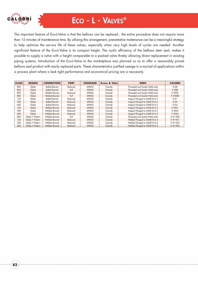
ECO - L - VALVES®
The important feature of Eco-L-Valve is that the bellows can be replaced , the entire procedure does not require morethan 15 minutes of maintenance time. By utilizing this arrangement, preventative maitenance can be a meaningful strategyto help optimize the service life of these valves, especially when very high levels of cycles are needed. Another significant feature of the Eco-L-Valve is its compact height. The cyclic efficiency of the bellows stem seal, makes it possible to supply a valve with a height comparable to a packed valve threby allowing direct replacement in existingpiping systems. Introduction of the Eco-L-Valve to the marketplace was planned so as to offer a reasonably priced bellows seal product with easily replaced parts. These characteristics justified useage in a myriad of applications withina process plant where a leak tight performance and economical pricing are a neccessity.
CLASS DESIGN CONNECTION PORT STANDARD Screw & Yoke ENDS CALOBRI800 Globe Bolted Bonnet Reduced API602 Outside Threaded and Socket Weld ends E D8800 Globe Bolted Bonnet Full API602 Outside Threaded and Socket Weld ends E D88800 Globe Welded Bonnet Reduced API602 Outside Threaded and Socket Weld ends E WD8800 Globe Welded Bonnet Full API602 Outside Threaded and Socket Weld ends E WD88150 Globe Bolted Bonnet Reduced API602 Outside Integral Flanged to ASME B16.5 E D1300 Globe Bolted Bonnet Reduced API602 Outside Integral Flanged to ASME B16.5 E D3600 Globe Bolted Bonnet Reduced API602 Outside Integral Flanged to ASME B16.5 E D6150 Globe Welded Bonnet Reduced API602 Outside Integral Flanged to ASME B16.5 E WD1300 Globe Welded Bonnet Reduced API602 Outside Integral Flanged to ASME B16.5 E WD3600 Globe Welded Bonnet Reduced API602 Outside Integral Flanged to ASME B16.5 E WD6800 Globe Y Pattern Welded Bonnet Full API602 Outside Threaded and Socket Weld ends E W-YD8150 Globe Y Pattern Welded Bonnet Reduced API602 Outside Welded Flanged to ASME B16.5 E W-YD1300 Globe Y Pattern Welded Bonnet Reduced API602 Outside Welded Flanged to ASME B16.5 E W-YD3600 Globe Y Pattern Welded Bonnet Reduced API602 Outside Welded Flanged to ASME B16.5 E W-YD6
82
ECO - L - VALVES®
Class 800 - 150 - 300 - 600Bolted Bonnet - Welded Bonnet

Design construction:API 602Testing according to API 598 - BS 6755Marking MSS SP25
Outside Screw and Yoke (OS&Y)Self aligning packing gland in two partsSpiral-wound gasket retained type Integral backseatSocket weld Ends to ANSI B16.11Screwed Ends (NOT) to ANSIB1.20.1
CLASS 800
CLASS 800
ECO - L - VALVES®
FULL BORE 1/4 3/8 1/2 3/4 1 1.1/4 1.1/2 2
End to End A inch 3.14 3.14 3.54 4.33 5.00 6.10 6.69 8.26mm 80 80 90 110 127 155 170 210
Handwheel B inch 3.14 3.14 3.14 4.33 5.11 7.08 7.08 7.08mm 80 80 80 110 130 180 180 180
Center to Top Open C inch 5.34 5.34 5.65 6.57 7.63 8.64 9.03 10.2mm 136 136 144 167 194 220 230 260
Dia. of Port D inch 0.28 0.35 0.51 0.69 0.89 1.16 1.38 1.79mm 7 9 13 17.5 22.5 29.5 35 45.5
Approx. WEIGHT - Lb 3.7 3.7 5.0 7.9 12.9 16.5 25.5 45.8Kg 1.7 1.7 2.3 3.6 5.9 7.5 11.6 20.8
FIGURE
BOLTED BONNETREDUCED BORE 1/2 3/4 1 1.1/4 1.1/2 2
End to End A inch 3.14 3.54 4.33 5.00 6.10 6.69mm 80 90 110 127 155 170
Handwheel B inch 3.14 3.14 4.33 5.11 7.08 7.08mm 80 80 110 130 180 180
Center to Top Open C inch 5.34 5.65 6.57 7.63 8.64 9.03mm 136 144 167 194 220 230
Dia. of Port D inch 0.35 0.51 0.69 0.89 1.16 1.38mm 9 13 17.5 22.5 29.5 35
Approx. WEIGHT - Lb 3.7 5.0 7.9 12.9 16.5 25.5Kg 1.7 2.3 3.6 5.9 7.5 11.6
FIGURE
BOLTED BONNET
FULL BORE 1/4 3/8 1/2 3/4 1 1.1/4 1.1/2 2
End to End A inch 3.14 3.14 3.54 4.33 5.00 6.10 6.69 8.26mm 80 80 90 110 127 155 170 210
Handwheel B inch 3.14 3.14 3.14 4.33 4.33 7.08 7.08 7.08mm 80 80 80 110 110 180 180 180
Center to Top Open C inch 3.54 3.54 5.65 6.57 7.63 8.64 9.03 10.2mm 136 136 144 167 194 220 230 260
Dia. of Port D inch 0.28 0.35 0.51 0.69 0.89 1.16 1.38 1.79mm 7 9 13 17.5 22.5 29.5 35 45.5
Approx. WEIGHT - Lb 3.7 3.7 5.0 7.9 12.9 16.0 23.1 41.8Kg 1.7 1.7 2.3 3.6 5.9 7.3 10.5 19.0
FIGURE
WELDED BONNET REDUCED BORE 1/2 3/4 1 1.1/4 1.1/2 2
End to End A inch 3.14 3.54 4.33 5.00 6.10 6.69mm 80 90 110 127 155 170
Handwheel B inch 3.14 3.14 4.33 4.33 7.08 7.08mm 80 80 110 110 180 180
Center to Top Open C inch 3.54 5.65 6.57 7.63 8.64 9.03mm 136 144 167 194 220 230
Dia. of Port D inch 0.35 0.51 0.69 0.89 1.16 1.38mm 9 13 17.5 22.5 29.5 35
Approx. WEIGHT - Lb 3.7 5.0 7.9 12.9 16.0 23.1Kg 1.7 2.3 3.6 5.9 7.3 10.5
FIGURE
WELDED BONNET
E D88
EW D88 EW D8
E D8
84

Design construction:API 602Testing according to API 598 - BS 6755Marking MSS SP25
Outside Screw and Yoke (OS&Y)Self aligning packing gland in two parts
Spiral-wound gasket retained type IntegralbackseatSocket weld Ends to ANSI B16.11Screwed Ends (NOT) to ANSIB1.20.1Butt Welding Ends to ANSI B.16.25End to end dimensions according to ANSIB16.10
ECO - L - VALVES®
CLASS 150 - 300 - 600REDUCED BORE 1/2 3/4 1 1.1/4 1.1/2 2
Class 150 A inch 4.25 4.64 5.00 - 6.49 7.99mm 108 118 127 - 165 203
End to End Class 300 A inch 6.02 7.00 7.99 - 9.01 10.5mm 153 178 203 - 229 267
Class 600 A inch 6.49 7.51 8.50 - 9.48 11.50mm 165 191 216 - 241 296
Handwheel B inch 3.14 3.14 4.33 - 5.11 7.08mm 80 80 110 - 130 180
Class 300/600 C inch 5.35 5.67 6.57 - 8.66 9.05
Center to Top openmm 136 144 167 - 220 230
Class 150 C inch 6.22 6.92 7.56 - 8.66 9.05mm 158 176 192 - 220 230
Dia. of Port D inch 0.35 0.51 0.69 - 1.16 1.38mm 9 13 17.5 - 29.5 35
Class 150 Lb 7.5 8.8 12.5 - 19.8 38.5Kg 3.4 4 5.7 - 9 17.5
Approx. Weight Class 300 Lb 8.8 11.0 16.1 - 30.8 40.0Kg 4 5 7.3 - 14 18.2
Class 600 Lb 9.9 12.1 16.5 - 33.0 44.0Kg 4.5 5.5 7.5 - 15.0 20.0
FIGURE
BOLTED BONNET - Integral Flanged Ends according to ANSI B15.5
CLASS 150 - 300 - 600REDUCED BORE 1/2 3/4 1 1.1/4 1.1/2 2
Class 150 A inch 4.25 4.64 5.00 - 6.49 7.99mm 108 118 127 - 165 203
End to EndClass 300 A inch 6.02 7.00 7.99 - 9.01 10.5
mm 153 178 203 - 229 267
Class 600 A inch 6.49 7.51 8.50 - 9.48 11.50mm 165 191 216 - 241 296
Handwheel B inch 3.14 3.14 4.33 - 5.11 7.08mm 80 80 110 - 130 180
Class 300/600 C inch 5.35 5.67 6.57 - 8.66 9.05
Center to Top openmm 136 144 167 - 220 230
Class 150 C inch 6.22 6.92 7.56 - 8.66 9.05mm 158 176 192 - 220 230
Dia. of Port D inch 0.35 0.51 0.69 - 1.16 1.38mm 9 13 17.5 - 29.5 35
Class 150 Lb 7.5 8.8 12.5 - 19.8 38.5Kg 3.4 4 5.7 - 9 17.5
Approx. Weight Class 300 Lb 8.8 11.0 16.1 - 30.8 40.0Kg 4 5 7.3 - 14 18.2
Class 600 Lb 9.9 12.1 16.5 - 33.0 44.0Kg 4.5 5.5 7.5 - 15.0 20.0
FIGURE
WELDED BONNET - Integral Flanged Ends according to ANSI B15.5
EW D1EW D3EW D6
E D1E D3E D6
85
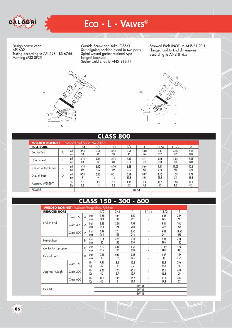
FULL BORE 1/4 3/8 1/2 3/4 1 1.1/4 1.1/2 2
End to End A inch 3.54 3.54 3.54 3.54 5.00 5.00 6.10 7.08mm 90 90 90 90 127 127 155 180
Handwheel B inch 3.14 3.14 3.14 4.33 5.11 5.11 7.08 7.08mm 80 80 80 110 130 130 180 180
Center to Top Open C inch 6.10 6.10 6.10 6.88 8.66 9.44 11.02 12.6mm 155 155 155 175 220 240 280 320
Dia. of Port D inch 0.28 0.35 0.51 0.69 0.89 1.16 1.38 1.79mm 7 9 13 17.5 22.5 29.5 35 45.5
Approx. WEIGHT - Lb 3.3 3.3 3.3 4.85 9.9 11.6 19.8 20.2Kg 1.5 1.5 1.5 2.2 4.5 5.3 9.0 9.2
FIGURE
Design construction:API 602Testing according to API 598 - BS 6755Marking MSS SP25
Outside Screw and Yoke (OS&Y)Self aligning packing gland in two partsSpiral-wound gasket retained typeIntegral backseatSocket weld Ends to ANSI B16.11
Screwed Ends (NOT) to ANSIB1.20.1Flanged End to End dimensionsaccording to ANSI B16.5
CLASS 150 - 300 - 600
CLASS 800WELDED BONNET - Threaded and Socket Weld Ends
REDUCED BORE 1/2 3/4 1 1.1/4 1.1/2 2
Class 150 A inch 4.25 4.64 5.00 - 6.49 7.99mm 108 118 127 - 165 203
End to EndClass 300 A inch 6.02 7.00 7.99 - 9.01 10.5
mm 153 178 203 - 229 267
Class 600 A inch 6.49 7.51 8.50 - 9.48 11.50mm 165 191 216 - 241 296
Handwheel B inch 3.14 4.33 5.11 - 7.08 7.08mm 80 110 130 - 180 180
Center to Top open C inch 6.10 6.88 8.66 - 11.02 12.6mm 155 175 220 - 280 320
Dia. of Port D inch 0.51 0.68 0.88 - 1.37 1.79mm 13 17.5 22.5 - 35 45.5
Class 150 Lb 7.04 8.8 15.8 - 32.8 39.6Kg 3.2 4 7.2 - 14.9 18
Approx. Weight Class 300 Lb 9.25 12.5 23.5 - 36.1 44.0Kg 4.2 5.7 10.7 - 16.4 20
Class 600 Lb 10.3 13.2 25.7 - 38.3 48.4Kg 4.7 6 11.7 - 17.4 22
FIGURE
WELDED BONNET - Welded Flange Ends Full Port
ECO - L - VALVES®
EW-YD8
EW-YD1EW-YD3EW-YD6
86

85
TECHNICAL DATA

PRESSURE TEMPERATURE RATINGS
Notes for pressure temperature tables:
1. Class 150 flanged end ratings end at 10000F (5380C)
2. A105, LF2 can be used up to 8000F (4270F)3. LF2 is suitable for use down to -500F( –460C)4. F11, F22 can be used up to 11000F (5930C)
5. F5, F9, F91 can be used up to 12000F (6500F)6. F304, F316, F321, F347 can be used down to –3200F (-1980C)7. Over 10000F (5380C) F304, F316, F321, F347 with 0.04% min. carbon
°F 150# 300# 600# 800# 900# 1500# 2500# 4500#(PSI) (PSI) (PSI) (PSI) (PSI) (PSI) (PSI) (PSI)
-20 290 750 1500 2000 2250 3750 6250 11250100 290 750 1500 2000 2250 3750 6250 11250200 260 750 1500 2000 2250 3750 6250 11250300 230 720 1455 1930 2165 3610 6070 10830400 200 695 1385 1850 2080 3465 5880 10400500 170 665 1330 1775 1995 3325 5540 9965600 140 605 1210 1615 1815 3025 5040 9070650 125 590 1175 1570 1765 2940 4905 8825700 110 570 1135 1515 1705 2840 4730 8515750 95 530 1065 1420 1595 2660 4430 7970800 80 510 1015 1355 1525 2540 4230 7610850 65 485 975 1300 1460 2435 4060 7305900 50 450 900 1200 1350 2245 3745 6740950 35 320 640 850 955 1595 3145 4785
1000 20 215 430 575 650 1080 2170 32401050 20 145 290 385 430 720 1455 21601100 20 95 190 255 290 480 915 14401150 20 60 125 165 185 310 570 9251200 15 40 75 100 115 190 345 565
F11 PSIT °C PN20 PN50 PN100 PN140 PN150 PN250 PN420 PN760
(BAR) (BAR) (BAR) (BAR) (BAR) (BAR) (BAR) (BAR) --29 20.0 51.7 103.4 137.9 155.2 258.6 431.0 775.90 20.0 51.7 103.4 137.9 155.2 258.6 431.0 775.9
50 19.5 51.7 103.4 137.9 155.2 258.6 431.0 775.9100 17.7 51.5 103.1 137.4 154.5 257.5 429.5 772.4150 15.8 49.6 100.2 133.0 149.2 248.8 418.4 746.3200 14.0 48.1 95.9 128.0 143.9 239.8 406.6 719.6250 12.1 46.2 92.4 123.3 138.6 231.1 386.2 692.6300 10.2 42.9 85.8 114.5 128.6 214.4 357.2 642.8350 8.4 40.4 80.4 107.4 120.7 201.1 335.4 603.5375 7.4 38.9 77.6 103.6 116.5 194.1 323.3 582.0400 6.5 36.5 73.3 97.8 109.8 183.1 305.0 548.7425 5.6 35.3 70.2 93.7 105.5 175.7 292.6 526.3450 4.6 33.7 67.7 90.3 101.4 169.1 281.9 507.2475 3.7 31.7 63.4 84.6 95.1 158.2 263.9 475.0500 2.8 25.3 50.6 67.3 75.7 126.1 231.8 378.5525 1.9 18.2 36.3 48.4 54.5 90.8 180.6 272.5550 1.4 12.7 25.4 33.9 38.2 63.6 128.0 190.7575 1.4 8.8 17.7 23.5 26.4 44.0 87.7 132.1600 1.4 6.0 12.0 16.1 18.3 30.3 57.4 90.8625 1.3 3.9 8.1 10.8 12.1 20.2 37.1 60.3649 1.0 2.8 5.2 6.9 7.9 13.1 23.8 39.0
F11 METRIC
°F 150# 300# 600# 800# 900# 1500# 2500# 4500#(PSI) (PSI) (PSI) (PSI) (PSI) (PSI) (PSI) (PSI)
-20 285 740 1480 1975 2220 3705 6170 11110100 285 740 1480 1975 2220 3705 6170 11110200 260 675 1350 1800 2025 3375 5625 10120300 230 655 1315 1750 1970 3280 5470 9845400 200 635 1270 1690 1900 3170 5280 9505500 170 600 1200 1595 1795 2995 4990 8980600 140 550 1095 1460 1640 2735 4560 8210650 125 535 1075 1430 1610 2685 4475 8055700 110 535 1065 1420 1600 2665 4440 7990750 95 505 1010 1345 1510 2520 4200 7560800 80 410 825 1100 1235 2060 3430 6170
A105 LF2 PSIT °C PN20 PN50 PN100 PN140 PN150 PN250 PN420 PN760
(BAR) (BAR) (BAR) (BAR) (BAR) (BAR) (BAR) (BAR) --29 19.7 51.0 102.1 136.2 153.1 255.5 425.5 766.20 19.7 51.0 102.1 136.2 153.1 255.5 425.5 766.2
50 19.3 50.0 100.1 133.6 150.1 250.5 417.2 751.2100 17.7 46.4 92.8 123.7 139.2 232.0 386.6 695.7150 15.8 45.1 90.6 120.6 135.8 226.1 377.0 678.5200 14.0 43.9 87.8 116.9 131.4 219.2 365.2 657.4250 12.1 41.8 83.6 111.1 125.1 208.7 347.6 625.7300 10.2 38.9 77.5 103.3 116.1 193.6 322.8 581.1350 8.4 36.9 74.0 98.5 110.9 184.8 308.0 554.4375 7.4 36.6 72.9 97.2 109.5 182.4 303.9 546.9400 6.5 34.6 69.1 92.1 103.4 172.5 287.5 517.5425 5.6 28.7 57.7 76.9 86.3 144.0 239.7 431.3
A105 LF2 METRIC
88
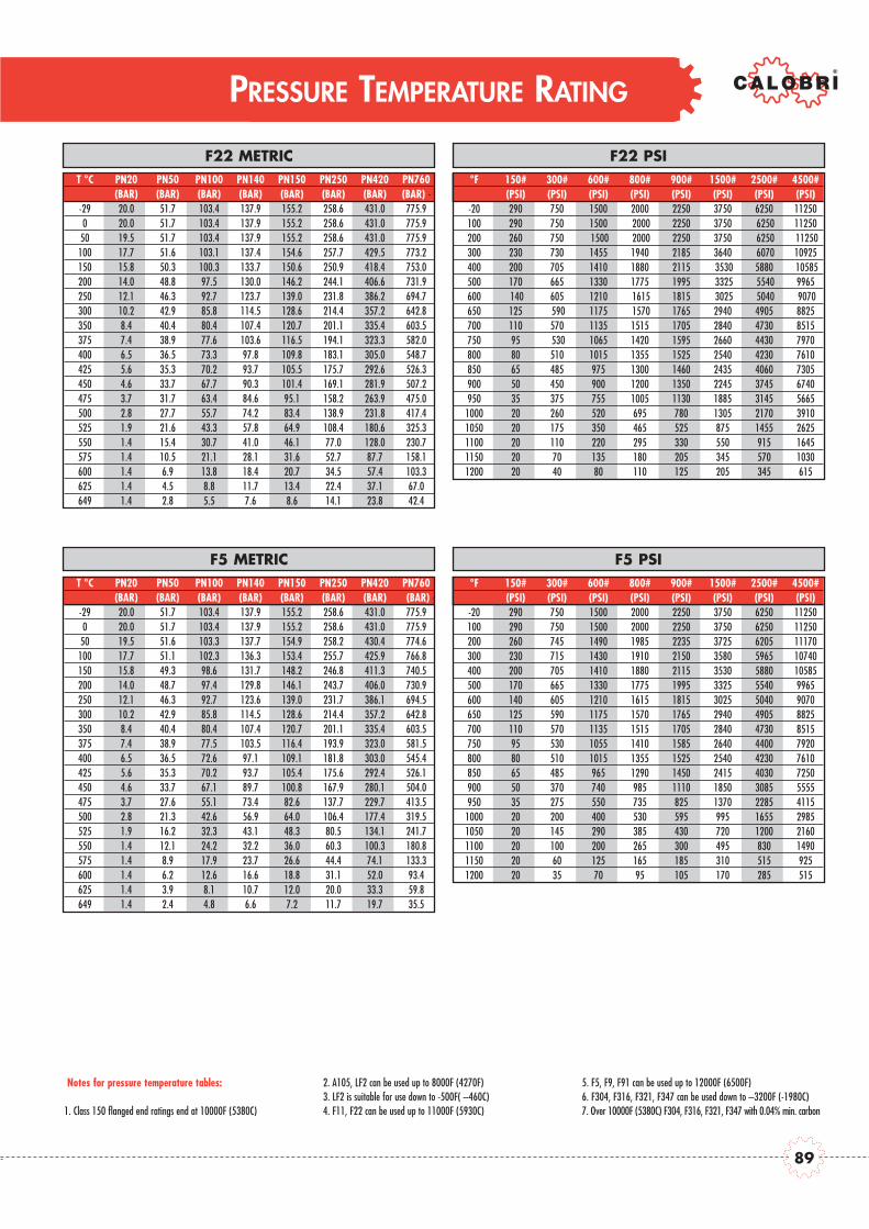
PRESSURE TEMPERATURE RATING
Notes for pressure temperature tables:
1. Class 150 flanged end ratings end at 10000F (5380C)
2. A105, LF2 can be used up to 8000F (4270F)3. LF2 is suitable for use down to -500F( –460C)4. F11, F22 can be used up to 11000F (5930C)
5. F5, F9, F91 can be used up to 12000F (6500F)6. F304, F316, F321, F347 can be used down to –3200F (-1980C)7. Over 10000F (5380C) F304, F316, F321, F347 with 0.04% min. carbon
°F 150# 300# 600# 800# 900# 1500# 2500# 4500#(PSI) (PSI) (PSI) (PSI) (PSI) (PSI) (PSI) (PSI)
-20 290 750 1500 2000 2250 3750 6250 11250100 290 750 1500 2000 2250 3750 6250 11250200 260 750 1500 2000 2250 3750 6250 11250300 230 730 1455 1940 2185 3640 6070 10925400 200 705 1410 1880 2115 3530 5880 10585500 170 665 1330 1775 1995 3325 5540 9965600 140 605 1210 1615 1815 3025 5040 9070650 125 590 1175 1570 1765 2940 4905 8825700 110 570 1135 1515 1705 2840 4730 8515750 95 530 1065 1420 1595 2660 4430 7970800 80 510 1015 1355 1525 2540 4230 7610850 65 485 975 1300 1460 2435 4060 7305900 50 450 900 1200 1350 2245 3745 6740950 35 375 755 1005 1130 1885 3145 5665
1000 20 260 520 695 780 1305 2170 39101050 20 175 350 465 525 875 1455 26251100 20 110 220 295 330 550 915 16451150 20 70 135 180 205 345 570 10301200 20 40 80 110 125 205 345 615
F22 PSIT °C PN20 PN50 PN100 PN140 PN150 PN250 PN420 PN760
(BAR) (BAR) (BAR) (BAR) (BAR) (BAR) (BAR) (BAR) --29 20.0 51.7 103.4 137.9 155.2 258.6 431.0 775.90 20.0 51.7 103.4 137.9 155.2 258.6 431.0 775.9
50 19.5 51.7 103.4 137.9 155.2 258.6 431.0 775.9100 17.7 51.6 103.1 137.4 154.6 257.7 429.5 773.2150 15.8 50.3 100.3 133.7 150.6 250.9 418.4 753.0200 14.0 48.8 97.5 130.0 146.2 244.1 406.6 731.9250 12.1 46.3 92.7 123.7 139.0 231.8 386.2 694.7300 10.2 42.9 85.8 114.5 128.6 214.4 357.2 642.8350 8.4 40.4 80.4 107.4 120.7 201.1 335.4 603.5375 7.4 38.9 77.6 103.6 116.5 194.1 323.3 582.0400 6.5 36.5 73.3 97.8 109.8 183.1 305.0 548.7425 5.6 35.3 70.2 93.7 105.5 175.7 292.6 526.3450 4.6 33.7 67.7 90.3 101.4 169.1 281.9 507.2475 3.7 31.7 63.4 84.6 95.1 158.2 263.9 475.0500 2.8 27.7 55.7 74.2 83.4 138.9 231.8 417.4525 1.9 21.6 43.3 57.8 64.9 108.4 180.6 325.3550 1.4 15.4 30.7 41.0 46.1 77.0 128.0 230.7575 1.4 10.5 21.1 28.1 31.6 52.7 87.7 158.1600 1.4 6.9 13.8 18.4 20.7 34.5 57.4 103.3625 1.4 4.5 8.8 11.7 13.4 22.4 37.1 67.0649 1.4 2.8 5.5 7.6 8.6 14.1 23.8 42.4
F22 METRIC
°F 150# 300# 600# 800# 900# 1500# 2500# 4500#(PSI) (PSI) (PSI) (PSI) (PSI) (PSI) (PSI) (PSI)
-20 290 750 1500 2000 2250 3750 6250 11250100 290 750 1500 2000 2250 3750 6250 11250200 260 745 1490 1985 2235 3725 6205 11170300 230 715 1430 1910 2150 3580 5965 10740400 200 705 1410 1880 2115 3530 5880 10585500 170 665 1330 1775 1995 3325 5540 9965600 140 605 1210 1615 1815 3025 5040 9070650 125 590 1175 1570 1765 2940 4905 8825700 110 570 1135 1515 1705 2840 4730 8515750 95 530 1055 1410 1585 2640 4400 7920800 80 510 1015 1355 1525 2540 4230 7610850 65 485 965 1290 1450 2415 4030 7250900 50 370 740 985 1110 1850 3085 5555950 35 275 550 735 825 1370 2285 4115
1000 20 200 400 530 595 995 1655 29851050 20 145 290 385 430 720 1200 21601100 20 100 200 265 300 495 830 14901150 20 60 125 165 185 310 515 9251200 20 35 70 95 105 170 285 515
F5 PSIT °C PN20 PN50 PN100 PN140 PN150 PN250 PN420 PN760
(BAR) (BAR) (BAR) (BAR) (BAR) (BAR) (BAR) (BAR) --29 20.0 51.7 103.4 137.9 155.2 258.6 431.0 775.90 20.0 51.7 103.4 137.9 155.2 258.6 431.0 775.9
50 19.5 51.6 103.3 137.7 154.9 258.2 430.4 774.6100 17.7 51.1 102.3 136.3 153.4 255.7 425.9 766.8150 15.8 49.3 98.6 131.7 148.2 246.8 411.3 740.5200 14.0 48.7 97.4 129.8 146.1 243.7 406.0 730.9250 12.1 46.3 92.7 123.6 139.0 231.7 386.1 694.5300 10.2 42.9 85.8 114.5 128.6 214.4 357.2 642.8350 8.4 40.4 80.4 107.4 120.7 201.1 335.4 603.5375 7.4 38.9 77.5 103.5 116.4 193.9 323.0 581.5400 6.5 36.5 72.6 97.1 109.1 181.8 303.0 545.4425 5.6 35.3 70.2 93.7 105.4 175.6 292.4 526.1450 4.6 33.7 67.1 89.7 100.8 167.9 280.1 504.0475 3.7 27.6 55.1 73.4 82.6 137.7 229.7 413.5500 2.8 21.3 42.6 56.9 64.0 106.4 177.4 319.5525 1.9 16.2 32.3 43.1 48.3 80.5 134.1 241.7550 1.4 12.1 24.2 32.2 36.0 60.3 100.3 180.8575 1.4 8.9 17.9 23.7 26.6 44.4 74.1 133.3600 1.4 6.2 12.6 16.6 18.8 31.1 52.0 93.4625 1.4 3.9 8.1 10.7 12.0 20.0 33.3 59.8649 1.4 2.4 4.8 6.6 7.2 11.7 19.7 35.5
F5 METRIC
89

PRESSURE TEMPERATURE RATINGS
Notes for pressure temperature tables:
1. Class 150 flanged end ratings end at 10000F (5380C)
2. A105, LF2 can be used up to 8000F (4270F)3. LF2 is suitable for use down to -500F( –460C)4. F11, F22 can be used up to 11000F (5930C)
5. F5, F9, F91 can be used up to 12000F (6500F)6. F304, F316, F321, F347 can be used down to –3200F (-1980C)7. Over 10000F (5380C) F304, F316, F321, F347 with 0.04% min. carbon
°F 150# 300# 600# 800# 900# 1500# 2500# 4500#(PSI) (PSI) (PSI) (PSI) (PSI) (PSI) (PSI) (PSI)
-20 90 750 1500 2000 2250 3750 6250 11250100 290 750 1500 2000 2250 3750 6250 11250200 260 750 1500 2000 2250 3750 6250 11250300 230 730 1455 1940 2185 3640 6070 10925400 200 705 1410 1880 2115 3530 5880 10585500 170 665 1330 1775 1995 3325 5540 9965600 140 605 1210 1615 1815 3025 5040 9070650 125 590 1175 1570 1765 2940 4905 8825700 110 570 1135 1515 1705 2840 4730 8515750 95 530 1065 1420 1595 2660 4430 7970800 80 510 1015 1355 1525 2540 4230 7610850 65 485 975 1300 1460 2435 4060 7305900 50 450 900 1200 1350 2245 3745 6740950 35 375 755 1005 1130 1885 3145 5655
1000 20 255 505 675 760 1270 2115 38051050 20 170 345 460 515 855 1430 25701100 20 115 225 300 340 565 945 16951150 20 75 150 200 225 375 630 11301200 20 50 105 140 155 255 430 770
F9 PSIT °C PN20 PN50 PN100 PN140 PN150 PN250 PN420 PN760
(BAR) (BAR) (BAR) (BAR) (BAR) (BAR) (BAR) (BAR) --29 20.0 51.7 103.4 137.9 155.2 258.6 431.0 775.90 20.0 51.7 103.4 137.9 155.2 258.6 431.0 775.9
50 19.5 51.7 103.4 137.9 155.2 258.6 431.0 775.9100 17.7 51.6 103.1 137.4 154.6 257.7 429.5 773.2150 15.8 50.3 100.3 133.7 150.6 250.9 418.4 753.0200 14.0 48.8 97.5 130.0 146.2 244.1 406.6 731.9250 12.1 46.3 92.7 123.7 139.0 231.8 386.2 694.7300 10.2 42.9 85.8 114.5 128.6 214.4 357.2 642.8350 8.4 40.4 80.4 107.4 120.7 201.1 335.4 603.5375 7.4 38.9 77.6 103.6 116.5 194.1 323.3 582.0400 6.5 36.5 73.3 97.8 109.8 183.1 305.0 548.7425 5.6 35.3 70.2 93.7 105.5 175.7 292.6 526.3450 4.6 33.7 67.7 90.3 101.4 169.1 281.9 507.2475 3.7 31.7 63.4 84.6 95.1 158.2 263.9 475.0500 2.8 27.7 55.7 74.2 83.4 138.9 231.8 416.9525 1.9 21.4 42.8 57.0 64.2 107.1 178.5 321.1550 1.4 15.0 30.0 40.0 45.0 75.0 125.1 224.9575 1.4 10.4 21.0 28.0 31.4 52.2 87.2 156.7600 1.4 7.3 14.3 19.0 21.5 35.8 60.0 107.5625 1.4 4.9 9.9 13.2 14.8 24.7 41.5 74.5649 1.4 3.4 7.2 9.7 10.7 17.6 29.7 53.1
F9 METRIC
°F 150# 300# 600# 800# 900# 1500# 2500# 4500#(PSI) (PSI) (PSI) (PSI) (PSI) (PSI) (PSI) (PSI)
-20 275 720 1440 1920 2160 3600 6000 10800100 275 720 1440 1920 2160 3600 6000 10800200 230 600 1200 1600 1800 3000 5000 9000300 205 540 1080 1440 1620 2700 4500 8100400 190 495 995 1325 1490 2485 4140 7450500 170 465 930 1240 1395 2330 3880 6985600 140 435 875 1165 1310 2185 3640 6550650 125 430 860 1145 1290 2150 3580 6445700 110 425 850 1135 1275 2125 3540 6370750 95 415 830 1105 1245 2075 3460 6230800 80 405 805 1075 1210 2015 3360 6050850 65 395 790 1055 1190 1980 3300 5940900 50 390 780 1035 1165 1945 3240 5830950 35 380 765 1020 1145 1910 3180 5725
1000 20 320 640 855 965 1605 2675 48151050 20 310 615 820 925 1545 2570 46301100 20 255 515 685 770 1285 2145 38551150 20 60 400 530 595 995 1655 29851200 20 40 310 415 465 770 1285 23151250 20 20 225 20 340 565 945 16951300 20 20 170 20 255 430 715 12851350 20 20 125 20 185 310 515 9251400 20 20 95 20 145 240 400 7201450 15 15 70 15 105 170 285 5151500 10 10 55 10 80 135 230 410
F304 PSIT °C PN20 PN50 PN100 PN140 PN150 PN250 PN420 PN760
(BAR) (BAR) (BAR) (BAR) (BAR) (BAR) (BAR) (BAR) --29 19.0 49.7 99.3 132.4 149.0 248.3 413.8 744.80 19.0 49.7 99.3 132.4 149.0 248.3 413.8 744.8
50 18.3 47.8 95.7 127.6 143.5 239.2 398.6 717.5100 15.7 40.9 81.8 109.0 122.6 204.4 340.7 613.2150 14.1 37.2 74.4 99.2 111.5 185.9 309.8 557.7200 13.2 34.4 69.1 92.0 103.5 172.6 287.5 517.4250 12.0 32.5 65.0 86.6 97.4 162.7 270.9 487.7300 10.2 30.6 61.4 81.8 92.0 153.5 255.7 460.1350 8.4 29.6 59.1 78.8 88.7 147.9 246.2 443.2375 7.4 29.2 58.4 78.0 87.6 146.1 243.4 438.0400 6.5 28.6 57.2 76.1 85.8 142.9 238.3 429.2425 5.6 28.0 55.6 74.3 83.6 139.2 232.1 418.0450 4.6 27.4 54.6 73.0 82.3 136.9 228.2 410.9475 3.7 27.0 54.0 71.7 80.8 134.8 224.5 404.0500 2.8 26.5 53.1 70.7 79.5 132.6 220.8 397.4525 1.9 24.0 48.1 64.2 72.3 120.4 200.5 360.9550 1.4 21.8 43.4 57.9 65.3 108.9 181.3 326.5575 1.4 20.1 40.1 53.4 60.2 100.5 167.3 301.1600 1.4 14.4 33.6 44.7 50.2 83.8 139.8 251.5625 1.4 3.9 26.7 35.4 39.8 66.4 110.6 199.4650 1.4 2.7 21.1 27.5 31.7 52.5 87.7 157.9700 1.4 1.4 12.3 1.4 18.5 31.1 51.8 93.1725 1.4 1.4 9.4 1.4 14.0 23.5 39.1 70.2750 1.4 1.4 7.3 1.4 11.0 18.3 30.4 54.7775 1.2 1.2 5.6 1.2 8.5 13.9 23.3 42.0800 0.9 0.9 4.4 0.9 6.5 10.7 18.0 32.3
F304 METRIC
90
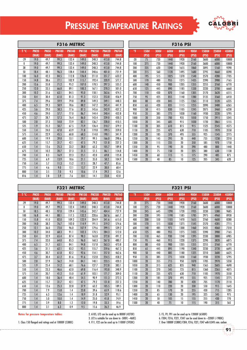
PRESSURE TEMPERATURE RATINGS
°F 150# 300# 600# 800# 900# 1500# 2500# 4500#(PSI) (PSI) (PSI) (PSI) (PSI) (PSI) (PSI) (PSI)
-20 275 720 1440 1920 2160 3600 6000 10800100 275 720 1440 1920 2160 3600 6000 10800200 245 645 1290 1720 1935 3230 5380 9685300 230 595 1190 1585 1785 2975 4960 8930400 200 550 1105 1470 1655 2760 4600 8280500 170 515 1030 1375 1545 2570 4285 7715600 140 485 975 1300 1460 2435 4060 7310650 125 480 955 1275 1435 2390 3980 7165700 110 465 930 1240 1395 2330 3880 6985750 95 460 915 1220 1375 2290 3820 6875800 80 450 900 1205 1355 2255 3760 6770850 65 445 895 1190 1340 2230 3720 6695900 50 440 885 1180 1325 2210 3680 6625950 35 385 775 1030 1160 1930 3220 5795
1000 20 355 715 950 1070 1785 2970 53501050 20 315 625 835 940 1565 2605 46901100 20 270 545 725 815 1360 2265 40751150 20 235 475 630 710 1185 1970 35501200 20 185 370 495 555 925 1545 27751250 20 140 280 20 420 705 1170 21101300 20 110 220 20 330 550 915 16451350 20 85 170 20 255 430 715 12851400 20 65 130 20 195 325 545 9751450 20 50 105 15 155 255 430 7701500 20 40 75 10 115 190 315 565
F321 PSIT °C PN20 PN50 PN100 PN140 PN150 PN250 PN420 PN760
(BAR) (BAR) (BAR) (BAR) (BAR) (BAR) (BAR) (BAR) --29 19.0 49.7 99.3 132.4 149.0 248.3 413.8 744.80 19.0 49.7 99.3 132.4 149.0 248.3 413.8 744.8
50 18.5 48.5 97.0 129.4 145.6 242.7 404.4 727.9100 16.8 44.1 88.1 117.5 132.2 220.6 367.6 661.7150 15.8 41.0 82.0 109.2 122.9 204.9 341.6 615.0200 14.0 38.2 76.7 102.0 114.9 191.5 319.2 574.6250 12.1 36.0 72.0 96.0 107.9 179.6 299.5 539.2300 10.2 34.0 68.3 91.1 102.3 170.5 284.3 512.0350 8.4 32.9 65.4 87.4 98.3 163.8 272.8 491.2375 7.4 32.0 64.0 85.3 96.0 160.3 267.0 480.7400 6.5 31.7 63.1 84.1 94.8 157.8 263.3 473.8425 5.6 31.1 62.1 83.2 93.5 155.7 259.6 467.3450 4.6 30.7 61.8 82.2 92.6 154.1 257.0 462.6475 3.7 30.4 61.2 81.6 91.6 152.8 254.5 458.2500 2.8 27.9 56.2 74.8 84.1 140.1 233.5 420.3525 1.9 25.4 51.2 68.1 76.6 127.7 212.8 383.1550 1.4 23.3 46.6 62.0 69.8 116.4 193.8 348.9575 1.4 20.7 41.2 55.0 61.9 103.1 171.7 309.0600 1.4 18.0 36.4 48.4 54.5 90.9 151.3 272.3625 1.4 15.7 31.7 42.1 47.5 79.2 131.8 237.3650 1.4 12.6 25.3 32.8 37.9 63.2 105.5 189.5700 1.4 7.9 15.8 1.4 23.8 39.6 65.9 118.6725 1.4 6.3 12.6 1.4 18.9 31.8 52.9 95.1750 1.4 5.0 10.0 1.4 14.9 25.0 41.8 74.9775 1.4 3.9 8.0 1.2 12.0 19.8 33.3 59.6800 1.4 3.1 6.3 0.9 9.5 15.6 26.2 46.9
F321 METRIC
Notes for pressure temperature tables:
1. Class 150 flanged end ratings end at 10000F (5380C)
2. A105, LF2 can be used up to 8000F (4270F)3. LF2 is suitable for use down to -500F( –460C)4. F11, F22 can be used up to 11000F (5930C)
5. F5, F9, F91 can be used up to 12000F (6500F)6. F304, F316, F321, F347 can be used down to –3200F (-1980C)7. Over 10000F (5380C) F304, F316, F321, F347 with 0.04% min. carbon
°F 150# 300# 600# 800# 900# 1500# 2500# 4500#(PSI) (PSI) (PSI) (PSI) (PSI) (PSI) (PSI) (PSI)
-20 75 720 1440 1920 2160 3600 6000 10800100 275 720 1440 1920 2160 3600 6000 10800200 235 620 1240 1655 1860 3095 5160 9290300 215 560 1120 1495 1680 2795 4660 8390400 195 515 1025 1370 1540 2570 4280 7705500 170 480 955 1275 1435 2390 3980 7165600 140 450 900 1205 1355 2255 3760 6770650 125 445 890 1185 1330 2220 3700 6660700 110 430 870 1160 1305 2170 3620 6515750 95 425 855 1140 1280 2135 3560 6410800 80 420 845 1125 1265 2110 3520 6335850 65 420 835 1115 1255 2090 3480 6265900 50 415 830 1105 1245 2075 3460 6230950 35 385 775 1030 1160 1930 3220 5795
1000 20 350 700 935 1050 1750 2915 52451050 20 345 685 915 1030 1720 2865 51551100 20 305 610 815 915 1525 2545 45751150 20 235 475 630 710 1185 1970 35501200 20 185 370 495 555 925 1545 27751250 20 145 295 20 440 735 1230 22101300 20 115 235 20 350 585 970 17501350 20 95 190 20 290 480 800 14401400 20 75 150 20 225 380 630 11301450 20 60 115 15 175 290 485 8751500 20 40 85 10 125 205 345 620
F316 PSIT °C PN20 PN50 PN100 PN140 PN150 PN250 PN420 PN760
(BAR) (BAR) (BAR) (BAR) (BAR) (BAR) (BAR) (BAR) --29 19.0 49.7 99.3 132.4 149.0 248.3 413.8 744.80 19.0 49.7 99.3 132.4 149.0 248.3 413.8 744.8
38 19.0 49.7 99.3 132.4 149.0 248.3 413.8 744.850 18.4 48.1 96.3 128.4 144.4 240.6 401.0 721.9
100 16.0 42.3 84.5 112.8 126.8 211.0 351.7 633.2150 14.8 38.6 77.1 102.9 115.7 192.4 320.9 577.7200 13.6 35.8 71.2 95.2 107.0 178.5 297.3 535.2250 12.0 33.5 66.8 89.1 100.3 167.1 278.3 501.0300 10.2 31.6 63.1 84.5 95.0 158.1 263.6 474.5350 8.4 30.4 61.0 81.3 91.3 152.3 253.8 456.9375 7.4 29.6 59.9 79.8 89.8 149.3 249.1 448.3400 6.5 29.3 58.9 78.6 88.2 147.2 245.4 441.9425 5.6 29.0 58.3 77.6 87.3 145.6 242.9 437.2450 4.6 29.0 57.7 77.0 86.7 144.4 240.4 432.8475 3.7 28.7 57.3 76.4 86.0 143.4 239.0 430.3500 2.8 27.3 54.8 72.9 82.1 136.7 228.0 410.5525 1.9 25.2 50.7 67.5 75.9 126.4 210.7 379.2550 1.4 24.0 47.8 63.9 71.8 119.8 199.5 359.0575 1.4 22.9 45.5 60.8 68.3 114.0 190.1 341.9600 1.4 19.9 39.8 53.1 59.7 99.5 166.0 298.6625 1.4 15.7 31.7 42.1 47.5 79.2 131.8 237.3650 1.4 12.6 25.3 33.2 38.0 63.3 105.7 189.8675 1.4 10.2 20.7 27.3 31.5 51.5 86.1 154.8700 1.4 8.3 16.9 22.3 25.1 42.0 69.8 125.8725 1.4 6.9 13.9 18.6 21.1 35.0 58.2 104.9750 1.4 5.7 11.3 15.2 17.1 28.7 47.7 85.6775 1.4 4.6 9.0 12.1 13.7 22.9 38.0 68.4800 1.4 3.5 7.0 9.3 10.6 17.4 29.2 52.6816 1.4 2.8 5.9 7.6 8.4 14.1 23.8 42.8
F316 METRIC
91
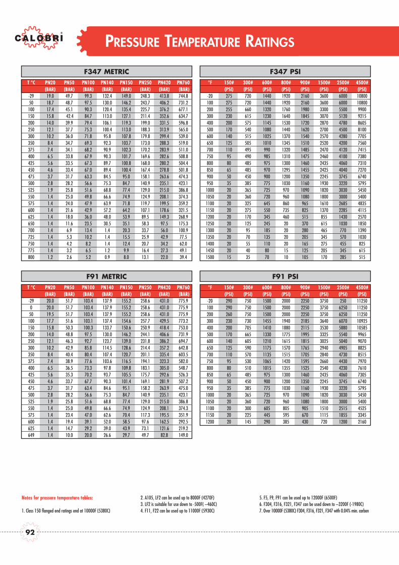
PRESSURE TEMPERATURE RATINGS
Notes for pressure temperature tables:
1. Class 150 flanged end ratings end at 10000F (5380C)
2. A105, LF2 can be used up to 8000F (4270F)3. LF2 is suitable for use down to -500F( –460C)4. F11, F22 can be used up to 11000F (5930C)
5. F5, F9, F91 can be used up to 12000F (6500F)6. F304, F316, F321, F347 can be used down to –3200F (-1980C)7. Over 10000F (5380C) F304, F316, F321, F347 with 0.04% min. carbon
°F 150# 300# 600# 800# 900# 1500# 2500# 4500#(PSI) (PSI) (PSI) (PSI) (PSI) (PSI) (PSI) (PSI)
-20 290 750 1500 2000 2250 3750 250 11250100 290 750 1500 2000 2250 3750 6250 11250200 260 750 1500 2000 2250 3750 6250 11250300 230 730 1455 1940 2185 3640 6070 10925400 200 705 1410 1880 2115 3530 5880 10585500 170 665 1330 1775 1995 3325 5540 9965600 140 605 1210 1615 1815 3025 5040 9070650 125 590 1175 1570 1765 2940 4905 8825700 110 570 1135 1515 1705 2840 4730 8515750 95 530 1065 1420 1595 2660 4430 7970800 80 510 1015 1355 1525 2540 4230 7610850 65 485 975 1300 1460 2435 4060 7305900 50 450 900 1200 1350 2245 3745 6740950 35 385 775 1030 1160 1930 3220 5795
1000 20 365 725 970 1090 1820 3030 54501050 20 360 720 960 1080 1800 3000 54001100 20 300 605 805 905 1510 2515 45251150 20 225 445 595 670 1115 1855 33451200 20 145 290 385 430 720 1200 2160
F91 PSIT °C PN20 PN50 PN100 PN140 PN150 PN250 PN420 PN760
(BAR) (BAR) (BAR) (BAR) (BAR) (BAR) (BAR) (BAR) --29 20.0 51.7 103.4 137.9 155.2 258.6 431.0 775.90 20.0 51.7 103.4 137.9 155.2 258.6 431.0 775.9
50 19.5 51.7 103.4 137.9 155.2 258.6 431.0 775.9100 17.7 51.6 103.1 137.4 154.6 257.7 429.5 773.2150 15.8 50.3 100.3 133.7 150.6 250.9 418.4 753.0200 14.0 48.8 97.5 130.0 146.2 244.1 406.6 731.9250 12.1 46.3 92.7 123.7 139.0 231.8 386.2 694.7300 10.2 42.9 85.8 114.5 128.6 214.4 357.2 642.8350 8.4 40.4 80.4 107.4 120.7 201.1 335.4 603.5375 7.4 38.9 77.6 103.6 116.5 194.1 323.3 582.0400 6.5 36.5 73.3 97.8 109.8 183.1 305.0 548.7425 5.6 35.3 70.2 93.7 105.5 175.7 292.6 526.3450 4.6 33.7 67.7 90.3 101.4 169.1 281.9 507.2475 3.7 31.7 63.4 84.6 95.1 158.2 263.9 475.0500 2.8 28.2 56.6 75.3 84.7 140.9 235.1 423.1525 1.9 25.8 51.6 68.8 77.4 129.0 215.0 386.8550 1.4 25.0 49.8 66.6 74.9 124.9 208.1 374.3575 1.4 23.4 47.0 62.6 70.4 117.3 195.5 351.9600 1.4 19.4 39.1 52.0 58.5 97.6 162.5 292.5625 1.4 14.7 29.2 39.0 43.9 73.1 121.6 219.2649 1.4 10.0 20.0 26.6 29.7 49.7 82.8 149.0
F91 METRIC
°F 150# 300# 600# 800# 900# 1500# 2500# 4500#(PSI) (PSI) (PSI) (PSI) (PSI) (PSI) (PSI) (PSI)
-20 275 720 1440 1920 2160 3600 6000 10800100 275 720 1440 1920 2160 3600 6000 10800200 255 660 1320 1760 1980 3300 5500 9900300 230 615 1230 1640 1845 3070 5120 9215400 200 575 1145 1530 1720 2870 4780 8605500 170 540 1080 1440 1620 2700 4500 8100600 140 515 1025 1370 1540 2570 4280 7705650 125 505 1010 1345 1510 2520 4200 7560700 110 495 990 1320 1485 2470 4120 7415750 95 490 985 1310 1475 2460 4100 7380800 80 485 975 1300 1460 2435 4060 7310850 65 485 970 1295 1455 2425 4040 7270900 50 450 900 1200 1350 2245 3745 6740950 35 385 775 1030 1160 1930 3220 5795
1000 20 365 725 970 1090 1820 3030 54501050 20 360 720 960 1080 1800 3000 54001100 20 325 645 860 965 1610 2685 48351150 20 275 550 735 825 1370 2285 41151200 20 170 345 460 515 855 1430 25701250 20 125 245 20 370 615 1030 18501300 20 95 185 20 280 465 770 13901350 20 70 135 20 205 345 570 10301400 20 55 110 20 165 275 455 8251450 20 40 80 15 125 205 345 6151500 15 35 70 10 105 170 285 515
F347 PSIT °C PN20 PN50 PN100 PN140 PN150 PN250 PN420 PN760
(BAR) (BAR) (BAR) (BAR) (BAR) (BAR) (BAR) (BAR) --29 19.0 49.7 99.3 132.4 149.0 248.3 413.8 744.850 18.7 48.7 97.5 130.0 146.2 243.7 406.2 731.2
100 17.4 45.1 90.3 120.4 135.4 225.7 376.2 677.1150 15.8 42.4 84.7 113.0 127.1 211.4 352.6 634.7200 14.0 39.9 79.4 106.1 119.3 199.0 331.5 596.8250 12.1 37.7 75.3 100.4 113.0 188.3 313.9 565.0300 10.2 36.0 71.8 95.8 107.8 179.8 299.4 539.0350 8.4 34.7 69.3 92.3 103.7 173.0 288.3 519.0375 7.4 34.1 68.2 90.9 102.3 170.2 283.9 511.0400 6.5 33.8 67.9 90.3 101.7 169.6 282.6 508.8425 5.6 33.5 67.3 89.7 100.8 168.0 280.2 504.4450 4.6 33.4 67.0 89.4 100.4 167.4 278.8 501.8475 3.7 31.7 63.3 84.5 95.0 158.1 263.6 474.3500 2.8 28.2 56.6 75.3 84.7 140.9 235.1 423.1525 1.9 25.8 51.6 68.8 77.4 129.0 215.0 386.8550 1.4 25.0 49.8 66.6 74.9 124.9 208.1 374.3575 1.4 24.0 47.9 63.9 71.8 119.7 199.5 359.2600 1.4 21.6 42.9 57.2 64.2 107.1 178.6 321.5625 1.4 18.0 36.0 48.0 53.9 89.5 149.3 268.9650 1.4 11.6 23.5 30.5 35.1 58.3 97.5 175.3700 1.4 6.9 13.4 1.4 20.3 33.7 56.0 100.9725 1.4 5.3 10.2 1.4 15.5 25.9 42.9 77.5750 1.4 4.2 8.2 1.4 12.4 20.7 34.2 62.0775 1.4 3.2 6.5 1.2 9.9 16.4 27.3 49.1800 1.2 2.6 5.2 0.9 8.0 13.1 22.0 39.4
F347 METRIC
92

FLANGE DIMENSION
FLANGES - ASME B16.5
FLANGES ANSI - B16.5 RAISED FACE 600 & 1500 lb RING JOINT FACE
Bolt holes Ring Joint Facing
N Size H M F
1/2 3.50 89 0.44 11.5 1.38 34.9 2.38 60.3 4 0.62 16 - - - -3/4 3.88 98 0.50 13.0 1.69 42.9 2.75 69.8 4 0.62 16 - - - -1 4.25 108 0.56 14.5 2.00 50.8 3.12 79.4 4 0.62 16 2.50 63.5 1.875 47.62 0.250 6.3 R 15
1.1/4 4.62 117 0.62 16.0 2.50 63.5 3.50 88.9 4 0.62 16 2.88 73.0 2.250 57.15 0.250 6.3 R 171.1/2 5.00 127 0.69 17.5 2.88 73.0 3.88 98.4 4 0.62 16 3.25 82.5 2.562 65.07 0.250 6.3 R 19
2 6.00 152 0.75 19.5 3.62 92.1 4.75 120.6 4 0.75 20 4.00 102.0 3.250 82.55 0.250 6.3 R 221/2 3.75 95 0.56 14.5 1.38 34.9 2.62 66.7 4 0.62 16 2.00 51.0 1.344 34.14 0.219 5.6 R 113/4 4.62 117 0.62 16.0 1.69 42.9 3.25 82.5 4 0.75 20 2.50 63.5 1.688 42.88 0.250 6.3 R 131 4.88 124 0.69 17.5 2.00 50.8 3.50 88.9 4 0.75 20 2.75 70.0 2.000 50.80 0.250 6.3 R 16
1.1/4 5.25 133 0.75 19.5 2.50 63.5 3.88 98.4 4 0.75 20 3.12 79.5 2.375 60.32 0.250 6.3 R 181.1/2 6.12 156 0.81 21.0 2.88 73.0 4.50 114.3 4 0.88 23 3.56 90.5 2.688 68.28 0.250 6.3 R 20
2 6.50 165 0.88 22.5 3.62 92.1 5.00 127.0 8 0.75 20 4.25 108.0 3.250 82.55 0.312 7.9 R 231/2 3.75 95 0.56 14.5 1.38 34.9 2.62 66.7 4 0.62 16 2.00 51.0 1.344 34.14 0.219 5.6 R 113/4 4.62 117 0.62 16.0 1.69 42.9 3.25 82.5 4 0.75 20 2.50 63.5 1.688 42.88 0.250 6.3 R 131 4.88 124 0.69 17.5 2.00 50.8 3.50 88.9 4 0.75 20 2.75 70.0 2.000 50.80 0.250 6.3 R 16
1.1/4 5.25 133 0.81 21.0 2.50 63.5 3.88 98.4 4 0.75 20 3.12 79.5 2.375 60.32 0.250 6.3 R 181.1/2 6.12 156 0.88 22.5 2.88 73.0 4.50 114.3 4 0.88 23 3.56 90.5 2.688 68.28 0.250 6.3 R 20
2 6.50 165 1.00 25.5 3.62 92.1 5.00 127.0 8 0.75 20 4.25 108.0 3.250 82.55 0.312 7.9 R 231/2 4.75 121 0.88 22.5 1.38 34.9 3.25 82.5 4 0.88 23 2.38 60.5 1.562 39.67 0.250 6.3 R 123/4 5.12 130 1.00 25.5 1.69 42.9 3.50 88.9 4 0.88 23 2.62 66.5 1.750 44.45 0.250 6.3 R 141 5.88 149 1.12 29.0 2.00 50.8 4.00 101.6 4 1.00 26 2.81 71.5 2.000 50.80 0.250 6.3 R 16
1.1/4 6.25 159 1.12 29.0 2.50 63.5 4.38 111.1 4 1.00 26 3.19 81.0 2.375 60.32 0.250 6.3 R 181.1/2 7.00 178 1.25 32.0 2.88 73.0 4.88 123.8 4 1.12 29 3.62 92.0 2.688 68.28 0.250 6.3 R 20
2 8.50 216 1.50 38.5 3.62 92.1 6.50 165.1 8 1.00 26 4.88 124.0 3.750 95.25 0.312 7.9 R 241/2 5.23 133 1.20 30.5 1.38 34.9 3.50 88.9 4 0.88 23 2.55 65.0 1.688 42.88 0.250 6.3 R 133/4 5.51 140 1.25 32.0 1.69 42.9 3.74 95.2 4 0.88 23 2.87 73.0 2.000 50.80 0.250 6.3 R 16
1 6.25 159 1.37 35.0 2.00 50.8 4.24 107.9 4 1.00 26 3.24 82.5 2.374 60.32 0.250 6.3 R 181.1/4 7.24 184 1.51 38.5 2.50 63.5 5.12 130.2 4 1.12 29 3.99 101.5 2.844 72.24 0.312 7.9 R 211.1/2 7.99 203 1.75 44.5 2.88 73.0 5.74 146 4 1.25 32 4.50 114.5 3.250 82.55 0.312 7.9 R 23
2 9.25 235 2.00 51.0 3.62 92.1 6.74 171.4 8 1.12 29 5.25 133.5 4.000 101.60 0.312 7.9 R 26
25
00
150
06
00
30
015
0CLA
SS Size A C D B Ring N.Ring Joint Facing
CLAS
S
93

PACKING AND GASKET
Asbestos-free packing is composed by a series of rings of pure graphite. The sets is closed with two rings, topand bottom, anti-extrusion, manufactured in braided graphite. Both internal and external rings are treaded with corrosion inhibitor.
Asbestos-free gaskets used on bolted bonnet valves are of the spiral-wound type in Stainless Steel 316 and puregraphite. On class 1500 valves, ring-joint gaskets in accordance with ANSI B16.20 - API 6A can be used.
Spare Parts: CALOBRI mantains an extensive inventory of packing and gaskets spares. To individuate the requireone please refer to the information shown on CALOBRI’s data sheets (assembly drawings), indicating code and composition of the sets.
GRAFITE PACKINGTight control on stem and pac-king chamber walls finishingand material purity and den-sity in the packing guaranteea leakproof sealing to EPArequisitions.
ISO TESTINGValve cycle tester using a massspectrometer in sniffer mode tomeasure helium leakage from thevalve gland.
TA-LUFT TESTINGValve cycle tester with vacuumcollection tank directly connectedto the mass spectrometer
LANTERN PACKING(on request)The lantern ring solution provi-de a way to verify the packingoperation and a grease injec-tor option to increase packingseal.
EMISSION CONTROL OPTIONS
EMISSION CONTROL TESTING & QUALIFICATION
LIVE LOADINGBOLTS LOADED TYPE(on request)Two sets of Belleville springskeep gland flange pressure onpacking for long periods oftime without maintenance.
GARLOCK®
EVSP 9000(on request)CALOBRI offers this superiordesigned chevron-style graphitepacking.ISA testing qualification.
LIVE LOADINGGLAND LOADED TYPE(on request)Sets of belleville springs keepgland pressure on packing forlong periods of time withoutmaintenance.
ARMA-SEAL 312 (TM)
(on request)CALOBRI valves qualified toISO15848 testing using thisspecial designed packing.Shell 77/312 qualification.
ISO 15848 TESTINGEmission test with Temperatureand Pressure cycles combined.Detection by mass spectrometerin open ambient.
CALOBRI offers a wide range of solutions to control fugitive emissions in packed valves.
CALOBRI testing pro-gramme and results areavailable on request atwww.calobri.com
CALOBRI has beeninvolved in extensivetesting of various pac-king solutions whichlead to major impro-vements in the stan-dard design and qua-lification by the mainrelevant specifications.
PATEN
TED
PATEN
TED
DRAFT
94
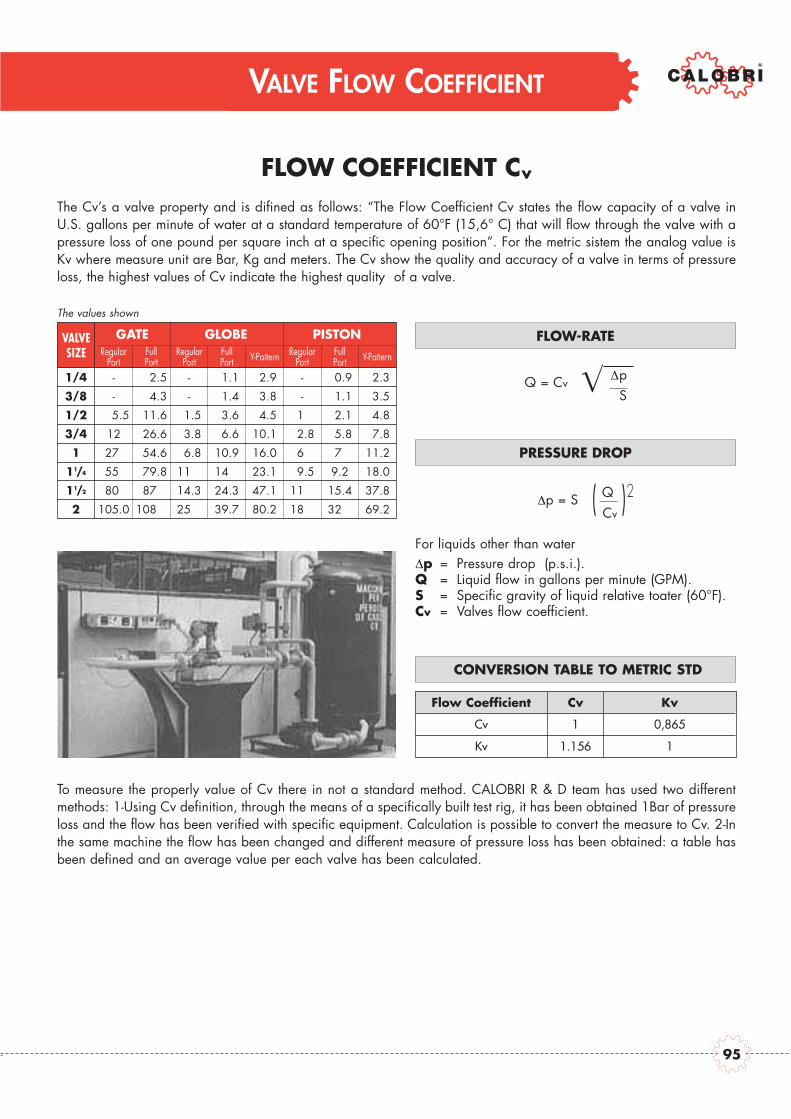
VALVE FLOW COEFFICIENT
FLOW COEFFICIENT Cv
The Cv’s a valve property and is difined as follows: “The Flow Coefficient Cv states the flow capacity of a valve inU.S. gallons per minute of water at a standard temperature of 60°F (15,6° C) that will flow through the valve with apressure loss of one pound per square inch at a specific opening position”. For the metric sistem the analog value isKv where measure unit are Bar, Kg and meters. The Cv show the quality and accuracy of a valve in terms of pressureloss, the highest values of Cv indicate the highest quality of a valve.
The values shown
For liquids other than waterp = Pressure drop (p.s.i.).
Q = Liquid flow in gallons per minute (GPM).S = Specific gravity of liquid relative toater (60°F).Cv = Valves flow coefficient.
FLOW-RATE
Q = CvpS
VALVESIZE
GATERegular
PortFull Port
GLOBERegular
Port Full Port Y-Pattern
PISTONRegular
Port Full Port Y-Pattern
PRESSURE DROP
p = S ( QCv
)2
To measure the properly value of Cv there in not a standard method. CALOBRI R & D team has used two differentmethods: 1-Using Cv definition, through the means of a specifically built test rig, it has been obtained 1Bar of pressureloss and the flow has been verified with specific equipment. Calculation is possible to convert the measure to Cv. 2-Inthe same machine the flow has been changed and different measure of pressure loss has been obtained: a table hasbeen defined and an average value per each valve has been calculated.
1/4 - 002.5 - 01.1 02.9 - 00.9 02.3
3/8 - 004.3 - 01.4 03.8 - 01.1 03.5
1/2 005.5 011.6 01.5 03.6 04.5 01.0 02.1 04.8
3/4 0125 026.6 03.8 06.6 10.1 02.8 05.8 07.8
1 027.0 054.6 06.8 10.9 16.0 06.5 07.0 11.2
11/4 055.5 079.8 11.5 14.0 23.1 09.5 9.2 18.0
11/2 080.0 087.0 14.3 24.3 47.1 11.0 15.4 37.8
2 105.0 108.0 25.0 39.7 80.2 18.0 32.0 69.2
CONVERSION TABLE TO METRIC STD
Flow Coefficient Cv Kv
Cv 1 0,865
Kv 1.156 1
VALVESIZE
GATERegular
PortRegular
PortRegular
PortFull Port
Full Port Y-Pattern Y-PatternFull
Port
GLOBE PISTON
95

END CONNECTIONS
BUTT WELD - ASME B16.25
SIZE SCHEDULE 40ØA T
SCHEDULE 80ØA T
SCHEDULE 160ØA T
SCHEDULE XXSØA T
mm mm mm mm mm mm mm mm
(In) (In) (In) (In) (In) (In) (In) (In)
21.3 2.77 21.3 3.73 21.3 4.78 21.3 7.47
(0.840) (0.190) (0.840) (0.147) (0.840) (0.188) (0.840) (0.294)
26.7 2.87 26.7 3.91 26.7 5.56 26.7 7.82
(1.050) (0.113) (1.050) (0.154) (1.050) (0.219) (1.050) (0.308)
33.4 3.38 33.4 4.55 33.4 6.35 33.4 9.09
(1.315) (0.133) (1.315) (0.179) (1.315) (0.250) (1.315) (0.358)
42.2 3.55 42.2 4.85 42.2 6.35 42.2 9.70
(1.660) (0.140) (1.660) (0.191) (1.660) (0.250) (1.660) (0.382)
48.3 3.68 48.3 5.08 48.3 7.14 48.3 10.15
(1.900) (0.145) (1.900) (0.200) (1.900) (0.281) (1.900) (0.400)
60.3 3.91 60.3 5.54 60.3 8.74 60.3 11.07
(2.375) (0.154) (2.375) (0.218) (2.375) (0.344) (2.375) (0.436)
73.0 5.15 73.0 7.01 73.0 9.53 73.0 14.02
(2.875) (0.203) (2.875) (0.276) (2.875) (0.375) (2.875) (0.552)
88.9 5.48 88.9 7.62 88.9 11.13 88.9 15.24
(3.500) (0.216) (3.500) (0.300) (3.500) (0.438) (3.500) (0.600)
114.3 6.02 114.3 8.56 114.3 13.49 114.3 17.12
(4.500) (0.237) (4.500) (0.337) (4.500) (0.531) (4.500) (0.674)
1/2”
3/4”
1”
1.1/4”
1.1/2”
2”
2.1/2”
3”
4”
-Fig. a
-Fig. b
-Fig. a 2”
-Fig. b > 2”
B = A - 2T
L (CALOBRI)Inch mm
0,44 11,1
0,44 11.1
0,5 12,7
0,57 14,5
0,63 16,0
0,69 17,5
0,75 19,0
0,86 22,0
SOCKET WELD - ASME B16.11
SIZE ØDInch mm
L (min)Inch mm
1/4” 0.555 14.10 0.38 9.53
3/8” 0.690 17.53 0.38 9.53
1/2” 0.855 21.72 0.38 9.53
3/4” 1.065 27.05 0.5 12.70
1” 1.330 33.78 0.5 12.70
1.1/4” 1.675 42.54 0.5 12.70
1.1/2” 1.915 48.64 0.5 12.70
2” 2.406 61.11 0.62 15.88
Socket wall thickness conform to ASME B16.34
SIZESCHEDULE 40ØA T
SCHEDULE 80ØA T
SCHEDULE 160ØA T
SCHEDULE XXSØA T
SIZE ØD L (min) L (CALOBRI)Inch Inch Inchmm mm mm
96
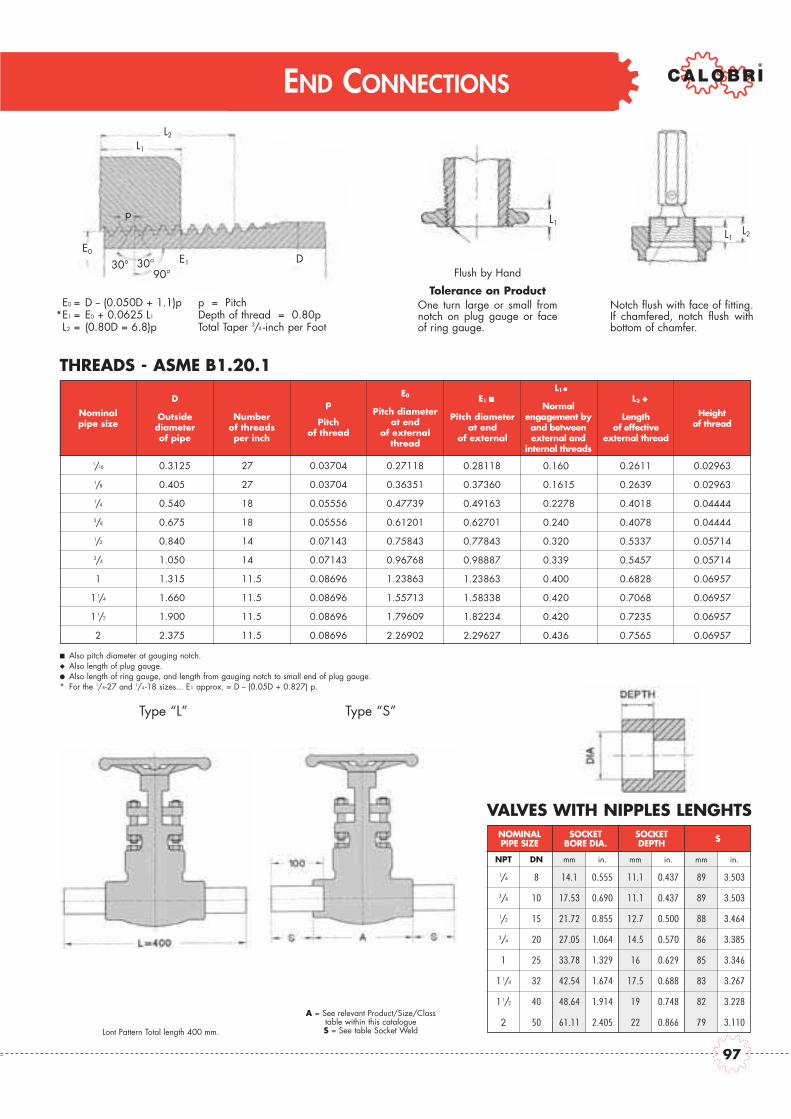
END CONNECTIONS
VALVES WITH NIPPLES LENGHTSNOMINAL SOCKET SOCKETPIPE SIZE BORE DIA. DEPTH S
E0 = D -- (0.050D + 1.1)pE1 = E0 + 0.0625 L1
L2 = (0.80D = 6.8)p
p = PitchDepth of thread = 0.80pTotal Taper 3/4 -inch per Foot
Flush by Hand
Tolerance on ProductOne turn large or small fromnotch on plug gauge or faceof ring gauge.
Also pitch diameter at gauging notch.Also length of plug gauge.Also length of ring gauge, and length from gauging notch to small end of plug gauge.
* For the 1/8-27 and 1/4 -18 sizes... E1 approx. = D -- (0.05D + 0.827) p.
Type “L”
A = See relevant Product/Size/Classtable within this catalogueS = See table Socket Weld
Type “S”
Notch flush with face of fitting.If chamfered, notch flush withbottom of chamfer.
*
THREADS - ASME B1.20.1
Nominalpipe size
DOutsidediameterof pipe
Numberof threadsper inch
pPitch
of thread
E0
Pitch diameterat end
of externalthread
E1
Pitch diameterat end
of external
L1
Normalengagement byand betweenexternal and
internal threads
L2
Lengthof effective
external thread
Heightof thread
1/16
1/8
1/4
3/8
1/2
3/4
1
1 1/4
1 1/2
2
0.3125
0.4050
0.5400
0.6750
0.8400
1.0500
1.3150
1.6600
1.9000
2.3750
27.0
27.0
18.0
18.0
14.0
14.0
11.5
11.5
11.5
11.5
0.03704
0.03704
0.05556
0.05556
0.07143
0.07143
0.08696
0.08696
0.08696
0.08696
0.27118
0.36351
0.47739
0.61201
0.75843
0.96768
1.23863
1.55713
1.79609
2.26902
0.28118
0.37360
0.49163
0.62701
0.77843
0.98887
1.23863
1.58338
1.82234
2.29627
0.1600
0.1615
0.2278
0.2400
0.3200
0.3390
0.4000
0.4200
0.4200
0.4360
0.2611
0.2639
0.4018
0.4078
0.5337
0.5457
0.6828
0.7068
0.7235
0.7565
0.02963
0.02963
0.04444
0.04444
0.05714
0.05714
0.06957
0.06957
0.06957
0.06957
NPT DN mm in. mm in. mm in.
1/4 8 14.1 0.555 11.1 0.437 89 3.503
3/8 10 17.53 0.690 11.1 0.437 89 3.503
1/2 15 21.72 0.855 12.7 0.500 88 3.464
3/4 20 27.05 1.064 14.5 0.570 86 3.385
1 25 33.78 1.329 16 0.629 85 3.346
1 1/4 32 42.54 1.674 17.5 0.688 83 3.267
1 1/2 40 48.64 1.914 19 0.748 82 3.228
2 50 61.11 2.405 22 0.866 79 3.110
L2
L1
E0E1
L1
L1L2
D
p
30° 30°90°
Lont Pattern Total length 400 mm.
D
Outside diameter of pipe
Nominal pipe size
Number of threads per inch
p
Pitch of thread
Height of thread
NOMINAL PIPE SIZE
SOCKET BORE DIA.
SOCKET DEPTH S
E0
Pitch diameter at end
of external thread
E1
Pitch diameter at end
of external
L2
Length of effective
external thread
L1
Normal engagement by and between external and
internal threads
97
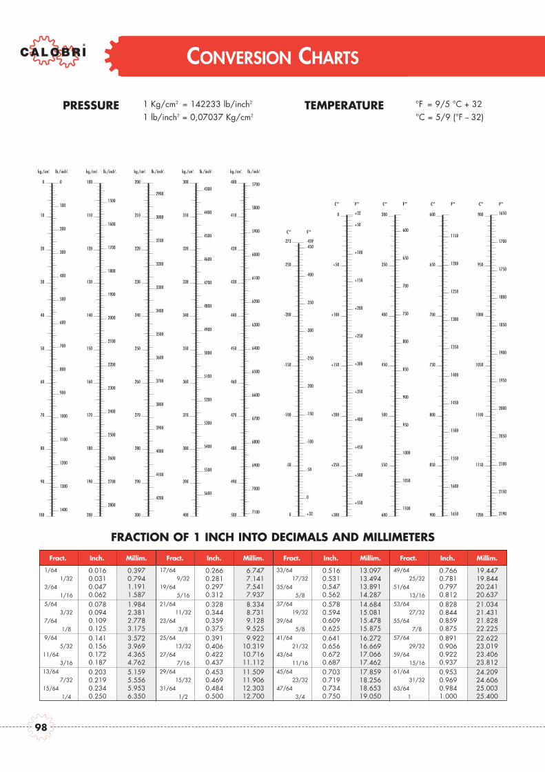
CONVERSION CHARTS
kg./cm2. lb./inch2.
0
100
200
300
400
500
600
700
800
900
1000
1100
1200
1300
1400
0
10
20
30
40
50
60
70
80
90
100
kg./cm2. lb./inch2.
1500
1600
1700
1800
1900
2000
2100
2200
2300
2400
2500
2600
2700
2800
100
110
120
130
140
150
160
170
180
190
200
kg./cm2. lb./inch2.
2900
3000
3100
3200
3300
3400
3500
3600
3700
3800
3900
4000
4100
4200
200
210
220
230
240
250
260
270
280
290
300
kg./cm2. lb./inch2.
4300
4400
4500
4600
4700
4800
4900
5000
5100
5200
5300
5400
5500
5600
300
310
320
330
340
350
360
370
380
390
400
kg./cm2. lb./inch2.
5700
5800
5900
6000
6100
6200
6300
6400
6500
6600
6700
6800
6900
7000
7100
400
410
420
430
440
450
460
470
480
490
500
-400
-350
-300
-250
-200
-150
-100
-50
0
-250
-200
-150
-100
-50
C° F°
-459-273
+320
-450
+50
+100
+150
+200
+250
+300
+350
+400
+450
+500
+550
0
+50
+100
+150
+200
+250
+300
C° F°
+32
1150
1200
1250
1300
1350
1400
1450
1500
1550
1600
1650
600
650
700
750
800
850
900
C° F°
600
650
700
750
800
850
900
950
1000
1050
1100
300
350
400
450
500
550
600
C° F°
PRESSURE 1 Kg/cm2 = 142233 lb/inch2
1 lb/inch2 = 0,07037 Kg/cm2
TEMPERATURE °F = 9/5 °C + 32°C = 5/9 (°F -- 32)
FRACTION OF 1 INCH INTO DECIMALS AND MILLIMETERS
Fract.
0.0160.0310.0470.062
1/641/32
3/641/16
0.3970.7941.1911.587
0.0780.0940.1090.125
5/643/32
7/641/8
1.9842.3812.7783.175
0.1410.1560.1720.187
9/645/32
11/643/16
3.5723.9694.3654.762
0.2030.2190.2340.250
13/647/32
15/641/4
5.1595.5565.9536.350
0.5160.5310.5470.562
33/6417/32
35/645/8
13.09713.49413.89114.287
0.5780.5940.6090.625
37/6419/32
39/645/8
14.68415.08115.47815.875
0.6410.6560.6720.687
41/6421/32
43/6411/16
16.27216.66917.06617.462
0.7030.7190.7340.750
45/6423/32
47/643/4
17.85918.25618.65319.050
0.7660.7810.7970.812
49/6425/32
51/6413/16
19.44719.84420.24120.637
0.8280.8440.8590.875
53/6427/32
55/647/8
21.03421.43121.82822.225
0.8910.9060.9220.937
57/6429/32
59/6415/16
22.62223.01923.40623.812
0.9530.9690.9841.000
61/6431/32
63/641
24.20924.60625.00325.400
0.2660.2810.2970.312
17/649/32
19/645/16
06.74707.14107.54107.937
0.3280.3440.3590.375
21/6411/32
23/643/8
08.33408.73109.12809.525
0.3910.4060.4220.437
25/6413/32
27/647/16
09.92210.31910.71611.112
0.4530.4690.4840.500
29/6415/32
31/641/2
11.50911.90612.30312.700
Inch. Millim. Fract. Inch. Millim. Fract. Inch. Millim. Fract. Inch. Millim.
2190
1650
1700
1750
1800
1850
1900
1950
2000
2050
2100
2150
900
950
1000
1050
1100
1150
1200
C° F°
Fract. Inch. Millim. Fract. Inch. Millim. Fract. Inch. Millim. Fract. Inch. Millim.
98

CONVERSION CHARTS
1 inch = 25,4 mm
Inch 0
0.0000.3970.7941.191
25.40025.79726.19426.591
50.80051.19751.59451.991
101.60102.00102.39102.79
127.00127.40127.79128.19
152.40152.80153.19153.59
177.80178.20178.59178.99
203.20203.60203.99204.39
228.60229.00229.39229.79
254.00254.40254.79255.19
279.40279.80280.19280.59
304.80305.20305.59305.99
330.20330.60330.99331.39
355.60356.00356.39356.79
76.20076.59776.99477.391
1 2 3 4 5 6 7 8 9 10 11 12 13 14
01/64
1/323/64
1.5871.9842.3812.778
26.98727.38427.78128.178
52.38752.78453.18153.578
103.19103.58103.98104.38
128.59128.98129.38129.78
153.99154.38154.78155.18
179.39179.78180.18180.58
204.79205.18205.58205.98
230.19230.58230.98231.38
255.59255.98256.38256.78
280.99281.38281.78282.18
306.39306.78307.18307.58
331.79332.18332.58332.98
357.19357.58357.98358.38
77.78778.18478.58178.978
1/165/64
3/327/64
3.1753.5723.9694.366
28.57528.97229.36929.766
53.97554.37254.76955.166
104.77105.17105.57105.97
130.17130.57130.97131.37
155.57155.97156.37156.77
180.97181.37181.77182.17
206.37206.77207.17207.57
231.77232.17232.57232.97
257.17257.57257.97258.37
282.57282.97283.37283.77
309.97308.37308.77309.17
333.37333.77334.17334.57
358.77359.17359.57359.97
79.37579.77280.16980.566
1/89/64
5/3211/64
4.7625.1595.5565.953
30.16230.55930.95631.353
55.56255.95956.35656.753
106.38106.76107.16107.55
131.76132.16132.56132.95
157.16157.56157.96158.35
182.56182.96183.36183.75
207.96208.36208.76209.15
233.36233.76234.16234.55
258.76259.16259.56259.95
285.16284.56284.96285.35
309.56309.96310.36310.75
334.96335.36335.76336.15
360.38360.76361.16361.55
80.96281.35981.75682.153
3/1613/64
7/3215/64
6.3506.7477.1447.541
31.75032.14732.54432.941
57.15057.54757.94458.341
107.95108.35108.74109.14
133.35133.75134.14134.54
158.75159.15159.54159.94
184.15184.55184.94185.34
209.55209.95210.34210.74
234.95235.35235.74236.14
260.35260.75261.14261.54
285.75286.15286.54286.94
311.15311.55311.94312.34
336.55336.95337.34337.74
361.95362.35362.74363.14
82.55082.94783.34483.741
1/417/64
9/3219/64
7.9378.3348.7319.128
33.33733.73434.13134.528
58.73759.13459.53159.928
109.54109.93110.33110.73
134.94135.33135.73136.13
160.34160.73161.13161.53
185.74186.13186.53186.93
211.14211.53211.93212.33
236.54236.93237.33237.73
261.94262.33262.73263.13
287.34287.73288.13288.53
312.74313.13313.53313.93
338.14338.53338.93339.33
363.54363.93364.33364.73
84.13784.53484.93185.328
5/1621/64
11/3223/64
9.5259.922
10.31910.716
34.92535.32235.71936.116
60.32560.72261.11961.516
111.12111.52111.92112.32
136.52136.92137.32137.72
161.92162.32162.72163.12
187.32187.72188.12188.52
212.72213.12213.52213.92
238.12238.52238.92239.32
263.52263.92264.32264.72
288.92289.32289.72290.12
314.32314.72315.12315.52
339.72340.12340.52340.92
365.12365.52365.92366.32
85.72586.12286.51986.916
3/825/64
13/3227/64
11.11211.50911.90612.303
36.51236.90937.30637.703
61.91262.30962.70663.103
112.71113.11113.51113.90
138.11138.51138.91139.30
163.51163.91164.31164.70
188.91189.31189.71190.10
214.31214.71215.11215.50
239.71240.11250.41240.90
265.11265.51265.91266.30
290.51290.91291.31291.70
315.91316.31316.71317.10
341.31341.71342.11342.50
366.71367.11367.51367.90
87.31287.70988.10688.503
7/1629/64
15/3231/64
12.70013.09713.49413.891
38.10038.49738.89439.291
63.50063.89764.29464.691
114.30114.70115.09115.49
139.70140.10140.49140.89
165.10165.50165.89166.29
190.50190.90191.29191.69
215.90216.30216.69217.09
241.30241.70242.09242.49
266.70267.10267.49267.89
292.10292.50292.89293.29
317.50317.90318.29318.69
342.90343.30343.69344.09
368.30368.70369.09369.49
88.90089.29789.69490.091
1/233/64
17/3235/64
14.28714.68415.08115.478
39.68740.08440.48140.878
65.08765.48465.88166.278
115.89116.28116.68117.08
141.29141.68142.08142.48
166.69167.08167.48167.88
192.09192.48192.88193.28
217.49217.88218.28218.68
242.89243.28243.68244.08
268.29268.68269.08269.48
293.69294.08294.48294.88
319.09319.48319.88320.28
344.49344.88345.28345.68
369.89370.28370.68371.08
90.48790.88491.28191.678
9/1637/64
19/3239/64
15.87516.27216.66917.066
41.27541.67242.06942.466
66.67567.07267.46967.866
117.47117.87118.27118.67
142.87143.27143.67144.07
168.27168.67169.07169.47
193.67194.07194.47194.87
219.07219.47219.87220.27
244.47244.87245.27245.67
269.87270.27270.67271.07
295.27295.67296.07296.47
320.67321.07321.47321.87
346.07346.47346.87347.27
371.47371.87372.27372.67
92.07592.47292.86993.266
5/841/64
21/3243/64
17.46217.85918.25618.635
42.86243.25943.65644.053
68.26268.65969.05669.453
119.06119.46119.86120.25
144.46144.86145.26145.65
169.86170.26170.66171.05
195.26195.66196.06196.45
220.66221.06221.46221.85
246.06246.46246.86247.25
271.46271.86272.26272.65
296.86297.26297.66298.05
322.26322.66323.06323.45
347.66348.06348.46348.85
373.06373.46373.86374.25
93.66294.05994.45694.853
11/1645/64
23/3247/64
19.05019.44719.84420.241
44.45044.48745.24445.641
69.85070.24770.64471.041
120.65121.05121.44121.84
146.05146.45146.84147.24
171.45171.85172.24172.64
196.85197.25197.64198.04
222.25222.65223.04223.44
247.65248.05248.44248.84
273.05273.45273.84274.24
298.45298.85299.24299.64
232.85234.25234.64235.04
349.25349.65350.04350.44
374.65375.05375.44375.84
95.25095.64796.04496.441
3/449/64
25/3251/64
20.63721.03421.43121.828
46.03746.43446.83147.228
71.43771.83472.23172.628
122.24122.63123.03123.43
147.64148.03148.43148.83
173.04173.43173.83174.23
198.44198.83199.23199.63
223.84224.23224.63225.03
249.24249.63250.03250.43
274.64275.03275.43275.83
300.04300.43300.83301.23
325.44325.83326.23326.63
350.84351.23351.63352.03
376.24376.63377.03377.43
96.83797.23497.63198.028
13/1653/64
27/3255/64
22.22522.62223.01923.416
47.62548.02248.41948.816
73.02573.42273.81974.216
123.82124.22124.62125.02
149.22149.62150.02150.42
174.62175.02175.42175.82
200.02200.42200.82201.22
225.42225.82226.22226.62
250.82251.22251.62252.02
276.22276.62277.02277.42
301.62302.02302.42302.82
327.02327.42327.82328.22
352.42352.82353.22353.62
377.82378.22378.62379.02
98.42598.82299.21999.616
7/857/64
29/3259/64
23.81224.20924.60625.003
49.21249.60950.00650.403
74.61275.00975.40675.803
125.41125.81126.21126.60
150.81151.21151.61152.00
176.21176.61177.01177.40
201.61202.01202.41202.80
227.01227.41227.81228.20
252.41252.81253.21253.60
277.81278.21278.61279.00
303.21303.61304.01304.40
328.61329.01329.41329.80
354.01354.41354.81355.20
379.41379.81380.21380.63
100.010100.410100.810101.200
15/1661/64
31/3263/64
Inch. 0 1 2 3 4 5 6 7 8 9 10 11 12 13 14
99

CORROSION DATAS
CORROSIVE MEDIA
A = Substantial resistance - Preferred material of construction.B = Moderate resistance - Satisfactory for use under most conditions.C = Questionable resistance - Use with caution.D = Inadequate resistance - Not recommended.
CALOBRI doesn't assume any responsibility from the use of a.m. data which are purely theoretical. The user must verify the best conditions of use.
Acetate Solvents, Crude D A A A B
Acetate Solvents, Pure C A A A A
Acetic Acid, 95% D B A A A
Acetic Anhydride, Boiling D B A A A
Acetone B A A A A
Alcohols B A A A A
Amines B A A A A
Ammonia, Anhydrous B A A A A
Ammonium Hydroxide, Hot B A A A D
Ammonium Nitrate B A A A C
Aniline Hydrochloride D D C B B
Antimony Trichloride D D C B B
Asphalt B A A A A
Barium Chloride, 5% C A A A A
Barium Hydroxide C A A A A
Barium Nitrate C A A B C
Benzene, Hot B A A A A
Benzoic Acid B A A A A
Blood D A A A A
Bromine, Dry Gas D A A B A
Bromine, Moist Gas D D D D C
Buttermilk D A A A A
Calcium Bisulfite, Hot D C B D D
Calcium Chloride, Dilute C B A A A
Calcium Hydroxide, 20%, Boiling D A A A A
Calcium Hydrochloride, < 2% C C B B C
Carbolic Acid, 90% C A A A B
Carbon Dioxide, Dry C A A A A
Carbon Disulphide B A A A B
Chloroacetic Acid D D C B B
Chloric Acid D D C C C
Chlorinated Water, Sat. D D C C C
Chlorine, Dry Gas B B B A A
Chlorine, Moist Gas D D C D C
Citric Acid, Dilute D A A A A
Citric Acid, Hot, Conc. D C B B B
Creosote, Hot B A A A A
Cupric Chloride, 5% D D C D D
Ethyl Chloride A A A A A
Ethylene Glycol A A A A A
Ferric Chloride < 1% D C B B C
Ferric Nitrate, 5% D B A C D
Ferric Sulfate, 5% D B A B C
Ferrous Sulfate, 10% C A A B A
Flourine, Dry Gas C C B A A
Flourine, Moist Gas D D D B A
Freon, Wet C C C B A
Fuel Oil, 140°F A A A A B
Carb
on S
teel
Stain
less
Ste
el 3
04
Stain
less
Ste
el 3
16
Inco
nel
Monel CORROSIVE MEDIA
Furfural B B B B B
Gasoline Sour B A A C C
Gasoline Refined A A A B A
Gelatine D B A A A
Glucose B A A A A
Glycerine B A A A A
Hydrofluoric Acid, Boiling D D D D B
Hydrofluosilicic Acid D D C B A
Hydrogen Chloride, Dry B D C A A
Hydrogen Chloride, Moist D D D D C
Hydrogen Fluoride, Dry C D C A A
Hydrogen Peroxide, Boiling D C B B B
Hydrogen Sulfide, Dry B A A A A
Hydrogen Sulfide, Moist C B A A B
Iodine, Dry D D B A A
Kerosene A A A A A
Lactic Acid, 5% D B A A B
Lactic Acid, 10% D B A A B
Lactic Acid, Boiling, 5% D C B B C
Lactic Acid, Boiling, 10% D D B B C
Lead Acetate, Hot D A A B B
Magnesium Chloride, Hot, 5% D C B A A
Magnesium Hydroxide B A A A A
Magnesium Sulfate B A A B A
Magnesium Sulfate, Boiling C A A C A
Mercury B A A A B
Mercuric Chloride, < 2% D D D D D
Mercuric Cyanide D B B B D
Methyl Chloride, Dry D B B A A
Milk D A A A B
Molasses B A A A A
Naptha B A A A A
Nickel Chloride D C B B B
Nickel Sulfate, Boiling D C C B A
Nitric Acid, 20% D A A B D
Nitric Acid, Boiling, Conc. D D D D D
Nitrous Acid D B B B C
Nitrobenzene D B A B B
Oils - Miner. B A A C B
Oxalic Acid, Boiling, 10% C A A A A
Oxalic Acid, Boiling, 50% D D C B B
Oxygen B A A A A
Picric Acid C A A D D
Potassium Bromide D C B A A
Potassium Carbonate B A A A A
Potassium Chlorate B A A A B
Potassium Chloride D A A A A
Potassium Chloride, Hot D C B B A
Carb
on S
teel
Stain
less
Ste
el 3
04
Stain
less
Ste
el 3
16
Inco
nel
Monel CORROSIVE MEDIA
Potassium Cyanide B B B B B
Potassium Sulfate, Dil. B A A A A
Propane, Liquid & Gas B A A A A
Pyrogallic Acid B A A B A
Rosin, Molten D A A A A
Salicylic Acid D B B B B
Silver Bromide D B A C B
Silver Chloride D D D C B
Silver Nitrate D A A A C
Sodium Acetate C A A A A
Sodium Bisulfate D B B B A
Sodium Bromide, Dil. D B B B A
Sodium Cyanide B B B B A
Sodium Fluoride, 5% D B A B A
Sodium Hydroxide, 50% B A A A A
Sodium Hyposulfite D B A B A
Sodium Nitrate B B A A B
Sodium Perborate C A A A B
Sodium Peroxide C A A A B
Sodium Phosphate, Tribasic C A A A A
Sodium Silicate B A A A B
Sodium Thiosulfate D B A B B
Stannous Chloride, Sat. D D B B B
Steam, 212°F A A A A A
Steam, 600°F C A A A A
Sulfite Liquors D C B D D
Sulfur Chloride D C D B B
Sulfur Dioxide, Moist D B A D D
Sulfuric Acid, Conc. B B B B D
Sulfurous Acid, Sat. D B B D D
Tannic Acid, 10% D A A B A
Tar, Hot B A A A B
Tartaric Acid, 120°F D B A A A
Toluene A A A A A
Trichlorethylene B A A A A
Turpentine B A A A A
Varnish, Hot C A A A A
Vegetable Oils B A A A B
Vinegar D A A A A
Water, Acid Mine D A A A C
Water, Boiler Feed B A A A A
Water, Distilled D A A A A
Water, Salt Sea D C B B A
Whiskey, Boiling D A A A C
Wine D A A A C
Xylene, Boiling D A A A A
Zinc Chloride, 5% D C B B B
Zinc Sulfate, Boiling D A A B A
Carb
on S
teel
Stain
less
Ste
el 3
04
Stain
less
Ste
el 3
16
Inco
nel
MonelCORROSIVE MEDIA
Carb
on S
teel
Stai
nles
s St
eel 3
04St
ainl
ess
Stee
l 316
Inco
nel
Mon
el CORROSIVE MEDIA
Carb
on S
teel
Stai
nles
s St
eel 3
04St
ainl
ess
Stee
l 316
Inco
nel
Mon
el CORROSIVE MEDIA
Carb
on S
teel
Stai
nles
s St
eel 3
04St
ainl
ess
Stee
l 316
Inco
nel
Mon
el
100

NOTE
101

VALVE DATA CAST STEEL

GATE VALVESGATE, GLOBE, SWING CHECK VALVES

This document is the property of Calobri. It must not be stored, reproduced or disclosed to others without written authorisation from the Company.
GATE VALVES
CLASS 150 LbTRIM NUMBER AS PER API 600
No Part Name 1 2 8 5 9 10 12 16
03 Seat Ring
410 304
STL Gr6 STL Gr6
MONEL 316
STL Gr6 STL Gr6
04 Wedge 410 STL Gr6
316
STL Gr6
05 Stem
410 410 31609 Backseat
Lantern Ring
13 Gland
BILL OF MATERIALS STANDARD ACCORDING TO ASTM
CARBON STEEL ALLOY STEEL STAINLESS STEEL
No Part Name WCB LCB WC6 C5 CF8 CF8M CF3 CF3M
01 Body A216 WCB A352LCB A217WC6 A217 C5 A351 CF8 A351 CF8M A351 CF3 A351 CF3M
02 Bonnet A216 WCB A352LCB A217WC6 A217 C5 A351 CF8 A351 CF8M A351 CF3 A351 CF3M
06 Bonnet Bolts A193-B7 A320-L7 A193-B16 A193-B8
07 Bonnet Nuts A194-2H A194-4 A194-4 A194-8
08 Body/Bonnet Gasket 304 SS + Graphite inhibited
10-11 Stem Packing Braided and Flexible Graphite
12 Eyebolts Pin A276-410
14 Gland Flange A216 WCB A352 LCB A217WC6 A217 C5 A351 CF8 A351 CF8M A351 CF3 A351 CF3M
15 Gland Eyebolts A193-B7 A320-L7 A193-B16 A193-B8
16 Gland Nuts A194-2H A194-4 A194-4 A194-8
17 Stem Nut ASTM A439-D2
18 Retaining Nut Carbon Steel 410
19 Hand Wheel Ductile Iron or Steel
20 Hand Wheel Nut Carbon Steel 410
21 Grease Nipple Stainless Steel
BASIC DESIGN STANDARDSBasic Design API 600 ANSI B16.34Face to FaceDimension ANSI B16.10Flanges Up to 24” ANSI B16.5 From 26” MSS SP44 ANSI B16.47 API 605Butt-weld ends ANSI B16.25Testing API 598
STANDARD DESCRIPTION- Outside Screw & Yoke- Bolted Bonnet with integral yoke up to Ø 8”- Bolted Bonnet with bolted yoke from Ø 10”- Welded Seat Ring- Solid wedge up to Ø 2-1/2”- Flexible Wedge from Ø 3” and greater- Available with Grear Operator- Special features according
to Customer’s requirement
TEST PRESSURE TO API 598 Psi/bar Shell (water) Seat (water) Seat (air) 450/30 314/22 80/5.5
L - RF
H (o
pen
posi
tion)
DØ
19
Integral yoke14
16
12
10*
03
01
05
06
02
21
04
13
07
08*
11*
09
15
17
20
18
L - BW
BW Welded-End version
ØD
a
Gear version
H1
* Recommended Spare Parts
104

CLASS 800
This document is the property of Calobri. It must not be stored, reproduced or disclosed to others without written authorisation from the Company.
GATE VALVES
CLASS 150 LbSIZE DIMENSION IN mm WEIGHT
Inches mm L(RF) L(BW) H Open H1 Ø D Ø Da Kg (HANDWHEEL) Kg (GEAR OPERATOR)
2” 50 178 216 390 - 200 - 19 -
2-12” 65 190 241 520 - 250 - 24 -
3” 80 203 282 530 - 250 - 33 -
4” 100 229 305 605 - 350 - 49 -
6” 150 267 403 780 - 350 305 87 -
8” 200 292 419 960 - 350 305 132 -
10” 250 330 457 1210 - 450 305 203 -
12” 300 356 502 1415 1465 500 305 265 291
14” 350 381 572 1532 1600 600 305 490 516
16” 400 406 610 1765 1820 600 460 535 561
18” 450 432 660 1965 2015 600 460 640 689
20” 500 457 711 2130 2180 600 460 780 830
22” 550 508 762 2385 2450 700 460 990 1040
24” 600 508 813 2565 2630 700 460 1190 1240
TEMP. WORKING PRESSURE (BAR.G)
°C Carbon Steel Alloy Steel Stainless SteelWCB (a)
LCB (b)
WC6 (c)
WC9 (c)
C5 (g)
C12 (g)
CF8 (d)
CF8M (d)
CF3 (e)
CF3M (f)
-29 to 38 19.6 18.4 19.8 19.8 20 20 19 19 19 19
50 19.2 18.2 19.5 19.5 19.5 19.5 18.3 18.4 18.3 18.4
100 17.7 17.4 17.7 17.7 17.7 17.7 15.7 16.2 15.7 16.2
150 15.8 15.8 15.8 15.8 15.8 15.8 14.2 14.8 14.2 14.8
200 13.8 13.8 13.8 13.8 13.8 13.8 13.2 13.7 13.2 13.7
250 12.1 12.1 12.1 12.1 12.1 12.1 12.1 12.1 12.1 12.1
300 10.2 10.2 10.2 10.2 10.2 10.2 10.2 10.2 10.2 10.2
350 8.4 8.4 8.4 8.4 8.4 8.4 8.4 8.4 8.4 8.4
400 6.5 6.5 6.5 6.5 6.5 6.5 6.5 6.5 6.5 6.5
425 5.5 5.5 5.5 5.5 5.5 5.5 5.5 5.5 5.5 5.5
450 4.6 4.6 4.6 4.6 4.6 4.6 4.6 4.6 4.6 4.6
500 2.8 2.8 2.8 2.8 2.8 2.8 2.8 2.8 2.8 2.8
538 1.4 1.4 1.4 1.4 1.4 1.4 1.4 1.4 1.4 1.4
550 - - 1.4 1.4 1.4 1.4 1.4 1.4 1.4 1.4
600 - - 1.4 1.4 1.4 1.4 1.4 1.4 1.4 1.4
650 - - - - - - 1.4 1.4 1.4 1.4
700 - - - - - - 1.4 1.4 1.4 1.4
750 - - - - - - 1.4 1.4 1.4 1.4
800 - - - - - - - - - -
(a) Permissible, but not recommended for prolonged usage above 425 °C(b) Not be used over 345 °C.(c) Permissible, but not recommended for prolonged usage above 595 °C Flanged End valve ratings terminate at 538°C.(d) At temperature above 538 °C, use only when carbon content is 0.04 % or higher. Flanged End valve ratings terminate at 538°C(e) Not be used over 425 °C. Flanged End valve ratings terminate at 538°C.(f) Not be used over 455 °C. Flanged End valve ratings terminate at 538°C.(g) Flanged End valve ratings terminate at 538°C.
ANSI CLASS 150 PRESSURE - TEMPERATURE RATINGS TO ANSI B16.34
105

This document is the property of Calobri. It must not be stored, reproduced or disclosed to others without written authorisation from the Company.
GATE VALVES
CLASS 300 LbTRIM NUMBER AS PER API 600
No Part Name 1 2 8 5 9 10 12 16
03 Seat Ring
410 304
STL Gr6 STL Gr6
MONEL 316
STL Gr6 STL Gr6
04 Wedge 410 STL Gr6
316
STL Gr6
05 Stem
410 410 31609 Backseat
Lantern Ring
13 Gland
BILL OF MATERIALS STANDARD ACCORDING TO ASTM
CARBON STEEL ALLOY STEEL STAINLESS STEEL
No Part Name WCB LCB WC6 C5 CF8 CF8M CF3 CF3M01 Body A216 WCB A352LCB A217WC6 A217 C5 A351 CF8 A351 CF8M A351 CF3 A351 CF3M
02 Bonnet A216 WCB A352LCB A217WC6 A217 C5 A351 CF8 A351 CF8M A351 CF3 A351 CF3M
06 Bonnet Bolts A193-B7 A320-L7 A193-B16 A193-B8
07 Bonnet Nuts A194-2H A194-4 A194-4 A194-8
08 Body/Bonnet Gasket 304 SS + Graphite inhibited
10-11 Stem Packing Braided and Flexible Graphite
12 Eyebolts Pin A276-410
14 Gland Flange A216 WCB A352 LCB A217WC6 A217C5 A351 CF8 A351 CF8M A351 CF3 A351 CF3M
15 Gland Eyebolts A193-B7 A320-L7 A193-B16 A193-B8
16 Gland Nuts A194-2H A194-4 A194-4 A194-8
17 Yoke
18 Stem Nut ASTM A439-D2
19 Retaining Nut Carbon Steel 410
20 Hand Wheel Ductile Iron or Steel
21 Hand Wheel Nut Carbon Steel 410
22 Grease Nipple Stainless Steel
BASIC DESIGN STANDARDSBasic Design API 600 ANSI B16.34Face to FaceDimension ANSI B16.10Flanges Up to 24” ANSI B16.5 From 26” MSS SP44 ANSI B16.47 API 605Butt-weld ends ANSI B16.25Testing API 598
STANDARD DESCRIPTION- Outside Screw & Yoke- Bolted Bonnet with integral yoke up to Ø 8”- Bolted Bonnet with bolted yoke from Ø 10”- Welded Seat Ring- Solid wedge up to Ø 2-1/2”- Flexible Wedge from Ø 3” and greater- Available with Grear Operetor- Special features according
to Customer’s requirement
TEST PRESSURE TO API 598 Psi/bar Shell (water) Seat (water) Seat (air) 1125/78 825/57 80/5.5
L - BW
BW Welded-End version
22
21
17
19
11*
13
15
08*
09
04
06
ØD
20
16
18
10*
12
14
07
02
01
03
05
H (o
pen
posi
tion)
Bolted yoke
L - RF
ØD
a
Gear version
H1
* Recommended Spare Parts
106
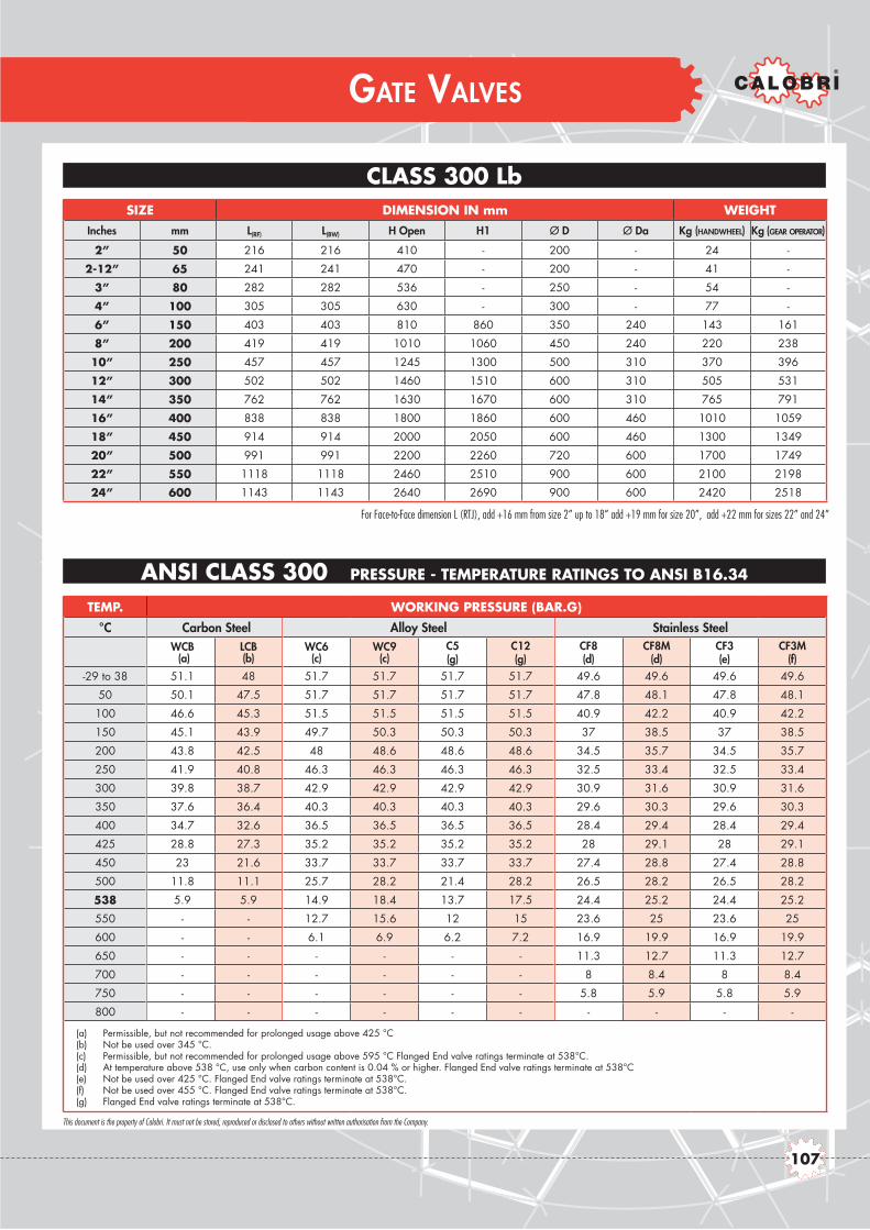
CLASS 800
This document is the property of Calobri. It must not be stored, reproduced or disclosed to others without written authorisation from the Company.
GATE VALVES
CLASS 300 LbSIZE DIMENSION IN mm WEIGHT
Inches mm L(RF) L(BW) H Open H1 Ø D Ø Da Kg (HANDWHEEL) Kg (GEAR OPERATOR)
2” 50 216 216 410 - 200 - 24 -
2-12” 65 241 241 470 - 200 - 41 -
3” 80 282 282 536 - 250 - 54 -
4” 100 305 305 630 - 300 - 77 -
6” 150 403 403 810 860 350 240 143 161
8” 200 419 419 1010 1060 450 240 220 238
10” 250 457 457 1245 1300 500 310 370 396
12” 300 502 502 1460 1510 600 310 505 531
14” 350 762 762 1630 1670 600 310 765 791
16” 400 838 838 1800 1860 600 460 1010 1059
18” 450 914 914 2000 2050 600 460 1300 1349
20” 500 991 991 2200 2260 720 600 1700 1749
22” 550 1118 1118 2460 2510 900 600 2100 2198
24” 600 1143 1143 2640 2690 900 600 2420 2518
TEMP. WORKING PRESSURE (BAR.G)
°C Carbon Steel Alloy Steel Stainless SteelWCB (a)
LCB (b)
WC6 (c)
WC9 (c)
C5 (g)
C12 (g)
CF8 (d)
CF8M (d)
CF3 (e)
CF3M (f)
-29 to 38 51.1 48 51.7 51.7 51.7 51.7 49.6 49.6 49.6 49.6
50 50.1 47.5 51.7 51.7 51.7 51.7 47.8 48.1 47.8 48.1
100 46.6 45.3 51.5 51.5 51.5 51.5 40.9 42.2 40.9 42.2
150 45.1 43.9 49.7 50.3 50.3 50.3 37 38.5 37 38.5
200 43.8 42.5 48 48.6 48.6 48.6 34.5 35.7 34.5 35.7
250 41.9 40.8 46.3 46.3 46.3 46.3 32.5 33.4 32.5 33.4
300 39.8 38.7 42.9 42.9 42.9 42.9 30.9 31.6 30.9 31.6
350 37.6 36.4 40.3 40.3 40.3 40.3 29.6 30.3 29.6 30.3
400 34.7 32.6 36.5 36.5 36.5 36.5 28.4 29.4 28.4 29.4
425 28.8 27.3 35.2 35.2 35.2 35.2 28 29.1 28 29.1
450 23 21.6 33.7 33.7 33.7 33.7 27.4 28.8 27.4 28.8
500 11.8 11.1 25.7 28.2 21.4 28.2 26.5 28.2 26.5 28.2
538 5.9 5.9 14.9 18.4 13.7 17.5 24.4 25.2 24.4 25.2
550 - - 12.7 15.6 12 15 23.6 25 23.6 25
600 - - 6.1 6.9 6.2 7.2 16.9 19.9 16.9 19.9
650 - - - - - - 11.3 12.7 11.3 12.7
700 - - - - - - 8 8.4 8 8.4
750 - - - - - - 5.8 5.9 5.8 5.9
800 - - - - - - - - - -
(a) Permissible, but not recommended for prolonged usage above 425 °C(b) Not be used over 345 °C.(c) Permissible, but not recommended for prolonged usage above 595 °C Flanged End valve ratings terminate at 538°C.(d) At temperature above 538 °C, use only when carbon content is 0.04 % or higher. Flanged End valve ratings terminate at 538°C(e) Not be used over 425 °C. Flanged End valve ratings terminate at 538°C.(f) Not be used over 455 °C. Flanged End valve ratings terminate at 538°C.(g) Flanged End valve ratings terminate at 538°C.
For Face-to-Face dimension L (RTJ), add +16 mm from size 2” up to 18” add +19 mm for size 20”, add +22 mm for sizes 22” and 24”
ANSI CLASS 300 PRESSURE - TEMPERATURE RATINGS TO ANSI B16.34
107
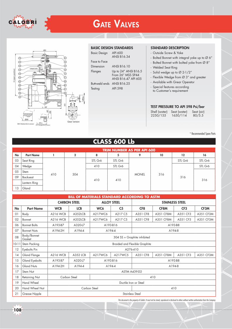
This document is the property of Calobri. It must not be stored, reproduced or disclosed to others without written authorisation from the Company.
GATE VALVES
CLASS 600 LbTRIM NUMBER AS PER API 600
No Part Name 1 2 8 5 9 10 12 16
03 Seat Ring
410 304
STL Gr6 STL Gr6
MONEL 316
STL Gr6 STL Gr6
04 Wedge 410 STL Gr6
316
STL Gr6
05 Stem
410 410 31609 Backseat
Lantern Ring
13 Gland
BILL OF MATERIALS STANDARD ACCORDING TO ASTM
CARBON STEEL ALLOY STEEL STAINLESS STEEL
No Part Name WCB LCB WC6 C5 CF8 CF8M CF3 CF3M
01 Body A216 WCB A352LCB A217WC6 A217 C5 A351 CF8 A351 CF8M A351 CF3 A351 CF3M
02 Bonnet A216 WCB A352LCB A217WC6 A217 C5 A351 CF8 A351 CF8M A351 CF3 A351 CF3M
06 Bonnet Bolts A193-B7 A320-L7 A193-B16 A193-B8
07 Bonnet Nuts A194-2H A194-4 A194-4 A194-8
08 Body/Bonnet Gasket 304 SS + Graphite inhibited
10-11 Stem Packing Braided and Flexible Graphite
12 Eyebolts Pin A276-410
14 Gland Flange A216 WCB A352 LCB A217WC6 A217WC5 A351 CF8 A351 CF8M A351 CF3 A351 CF3M
15 Gland Eyebolts A193-B7 A320-L7 A193-B16 A193-B8
16 Gland Nuts A194-2H A194-4 A194-4 A194-8
17 Stem Nut ASTM A439-D2
18 Retaining Nut Carbon Steel 410
19 Hand Wheel Ductile Iron or Steel
20 Hand Wheel Nut Carbon Steel 410
21 Grease Nipple Stainless Steel
BASIC DESIGN STANDARDSBasic Design API 600 ANSI B16.34Face to FaceDimension ANSI B16.10Flanges Up to 24” ANSI B16.5 From 26” MSS SP44 ANSI B16.47 API 605Butt-weld ends ANSI B16.25Testing API 598
STANDARD DESCRIPTION- Outside Screw & Yoke- Bolted Bonnet with integral yoke up to Ø 6”- Bolted Bonnet with bolted yoke from Ø 8”- Welded Seat Ring- Solid wedge up to Ø 2-1/2”- Flexible Wedge from Ø 3” and greater- Available with Grear Operetor- Special features according
to Customer’s requirement
TEST PRESSURE TO API 598 Psi/bar Shell (water) Seat (water) Seat (air) 2250/155 1650/114 80/5.5
20
17
18
11*
13
15
09
08*
04
07
19
16
21
10*
12
14
06
02
01
03
05
ØD
H (o
pen
posi
tion)
Integral yoke
L - RF
L - RTJ
ØP
ØN
RTJ Flanged-End version
L - BW
BW Welded-End version
ØD
a
Gear version
H1
* Recommended Spare Parts
108

CLASS 800
This document is the property of Calobri. It must not be stored, reproduced or disclosed to others without written authorisation from the Company.
GATE VALVES
ANSI CLASS 600 PRESSURE - TEMPERATURE RATINGS TO ANSI B16.34
CLASS 600 LbSIZE DIMENSION IN mm WEIGHT
Inches mm L(RF) L(BW) H Open H1 Ø D Ø Da Kg (HANDWHEEL) Kg (GEAR OPERATOR)
2” 50 292 292 425 - 200 - 33 -
2-12” 65 330 330 500 - 200 - 51 -
3” 80 356 356 570 - 250 - 70 -
4” 100 432 432 680 - 300 - 127 -
6” 150 559 559 895 940 500 500 280 306
8” 200 660 660 1085 1150 600 600 450 476
10” 250 787 787 1280 1310 600 600 760 809
12” 300 838 838 1500 1550 600 600 980 1029
14” 350 889 889 1660 1670 720 600 1240 1289
16” 400 991 991 1885 1940 720 800 1540 1638
18” 450 1092 1092 2040 2090 800 800 2250 2348
20” 500 1194 1194 2230 2280 1000 800 2700 2990
22” 550 1295 1295 2415 2470 1000 800 3200 3490
24” 600 1397 1397 2640 2690 1000 800 3800 4090
TEMP. WORKING PRESSURE (BAR.G)
°C Carbon Steel Alloy Steel Stainless SteelWCB (a)
LCB (b)
WC6 (c)
WC9 (c)
C5 (g)
C12 (g)
CF8 (d)
CF8M (d)
CF3 (e)
CF3M (f)
-29 to 38 102.1 96 103.4 103.4 103.4 103.4 99.3 99.3 99.3 99.3
50 100.2 94.9 103.4 103.4 103.4 103.4 95.6 96.2 95.6 96.2
100 93.2 90.7 103 103 103 103 81.7 84.4 81.7 84.4
150 90.2 87.9 99.5 100.3 100.3 100.3 74 77 74 77
200 87.6 85.1 95.9 97.2 97.2 97.2 69 71.3 69 71.3
250 83.9 81.6 92.7 92.7 92.7 92.7 65 66.8 65 66.8
300 79.6 77.4 85.7 85.7 85.7 85.7 61.8 63.2 61.8 63.2
350 75.1 72.8 80.4 80.4 80.4 80.4 59.3 60.7 59.3 60.7
400 69.4 65.2 73.3 73.3 73.3 73.3 56.9 58.9 56.9 58.9
425 57.5 54.6 70 70 70 70 56 58.3 56 58.3
450 46 43.2 67.7 67.7 67.7 67.7 54.8 57.7 54.8 57.7
500 23.5 22.1 51.5 56.5 42.8 56.5 53 56.5 53 56.5
538 11.8 11.8 29.8 36.9 27.4 35 48.9 50 48.9 50
550 - - 25.4 31.3 24.1 30 47.1 49.8 47.1 49.8
600 - - 12.2 13.8 12.5 14.4 33.8 39.8 33.8 39.8
650 - - - - - - 22.5 25.3 22.5 25.3
700 - - - - - - 16.1 16.8 16.1 16.8
750 - - - - - - 11.6 11.7 11.6 11.7
800 - - - - - - - - - -
(a) Permissible, but not recommended for prolonged usage above 425 °C(b) Not be used over 345 °C.(c) Permissible, but not recommended for prolonged usage above 595 °C Flanged End valve ratings terminate at 538°C.(d) At temperature above 538 °C, use only when carbon content is 0.04 % or higher. Flanged End valve ratings terminate at 538°C(e) Not be used over 425 °C. Flanged End valve ratings terminate at 538°C.(f) Not be used over 455 °C. Flanged End valve ratings terminate at 538°C.(g) Flanged End valve ratings terminate at 538°C.
For Face-to-Face dimension L (RTJ), add +3 mm from size 2” up to 18” add +6 mm for size 20”, add +10 mm for sizes 22” and 24”
109

This document is the property of Calobri. It must not be stored, reproduced or disclosed to others without written authorisation from the Company.
GLOBE VALVES
CLASS 150 LbTRIM NUMBER AS PER API 600
No Part Name 1 2 8 5 9 10 12 16
03 Seat Ring
410 304
STL Gr6 STL Gr6
MONEL 316
STL Gr6 STL Gr6
04 Disc 410 STL Gr6
316
STL Gr6
05 Stem
410 410 316
09 Backseat
Lantern Ring
13 Gland
22 Disc Nut
BILL OF MATERIALS STANDARD ACCORDING TO ASTM
CARBON STEEL ALLOY STEEL STAINLESS STEEL
No Part Name WCB LCB WC6 C5 CF8 CF8M CF3 CF3M
01 Body A216 WCB A352LCB A217WC6 A217 C5 A351 CF8 A351 CF8M A351 CF3 A351 CF3M
02 Bonnet A216 WCB A352LCB A217WC6 A217 C5 A351 CF8 A351 CF8M A351 CF3 A351 CF3M
06 Bonnet Bolts A193-B7 A320-L7 A193-B16 A193-B8
07 Bonnet Nuts A194-2H A194-4 A194-4 A194-8
08 Body/Bonnet Gasket 304 SS + Graphite inhibited
10-11 Stem Packing Braided and Flexible Graphite
12 Eyebolts Pin A276-410
14 Gland Flange A216 WCB A352 LCB A217WC6 A217WC5 A351 CF8 A351 CF8M A351 CF3 A351 CF3M
15 Gland Eyebolts A193-B7 A320-L7 A193-B16 A193-B8
16 Gland Nuts A194-2H A194-4 A194-4 A194-8
17 Stem Nut ASTM A439-D2
18 Stem Nut Screw Carbon Steel 410
19 Hand Wheel Ductile Iron or Steel
20 Washer Carbon Steel 410
21 Hand Wheel Nut Stainless Steel
BASIC DESIGN STANDARDSBasic Design BS 1873 ANSI B16.34Face to FaceDimension ANSI B16.10Flanges Up to 24” ANSI B16.5 From 26” MSS SP44 ANSI B16.47 API 605Butt-weld ends ANSI B16.25Testing API 598
STANDARD DESCRIPTION- Outside Screw & Yoke – Rising Stem- Rising Hand Wheel- Bolted Bonnet Joint- Screwed Seat Ring up to Ø 6”- Welded Seat Ring from Ø 8”- Swivel Plug Disc Standard Type- Available with Gear Operator- Special features according
to Customer’s requirement
TEST PRESSURE TO API 598 Psi/bar Shell (water) Seat (water) Seat (air) 450/30 314/22 80/5.5
L - BW
BW Welded-End version
ØD
a
Gear version
H1
03
L - RF
01
ØD
10*
22
05
02
06
12
14
16
19
21
04
08*
07
09
11*
13
15
17
18
20
H (C
lose
d)
* Recommended Spare Parts
110

CLASS 800
This document is the property of Calobri. It must not be stored, reproduced or disclosed to others without written authorisation from the Company.
GLOBE VALVES
CLASS 150 LbSIZE DIMENSION IN mm WEIGHT
Inches mm L(RF) L(BW) H Closed H1 Ø D Ø Da Kg (HANDWHEEL) Kg (GEAR OPERATOR)
2” 50 203 203 380 - 200 - 22 -
2-12” 65 216 216 415 - 245 - 30 -
3” 80 241 241 390 - 285 - 40 -
4” 100 292 292 470 - 285 - 60 -
6” 150 406 406 540 - 400 - 105 -
8” 200 495 495 605 - 600 - 170 -
10” 250 622 622 860 900 600 305 315 341
12” 300 698 698 935 975 600 460 475 525
14” 350 787 787 1070 1090 700 460 580 630
16” 400 914 914 1150 1160 1000 610 790 890
18” 450 978 978 1205 1275 1000 610 1020 1120
20” 500 978 978 - 1420 - 610 1250 1540
22” 550 1067 1067 - 1570 - 610 -
24” 600 1295 1295 - 1720 - 610 1960 2260
TEMP. WORKING PRESSURE (BAR.G)
°C Carbon Steel Alloy Steel Stainless SteelWCB (a)
LCB (b)
WC6 (c)
WC9 (c)
C5 (g)
C12 (g)
CF8 (d)
CF8M (d)
CF3 (e)
CF3M (f)
-29 to 38 19.6 18.4 19.8 19.8 20 20 19 19 19 19
50 19.2 18.2 19.5 19.5 19.5 19.5 18.3 18.4 18.3 18.4
100 17.7 17.4 17.7 17.7 17.7 17.7 15.7 16.2 15.7 16.2
150 15.8 15.8 15.8 15.8 15.8 15.8 14.2 14.8 14.2 14.8
200 13.8 13.8 13.8 13.8 13.8 13.8 13.2 13.7 13.2 13.7
250 12.1 12.1 12.1 12.1 12.1 12.1 12.1 12.1 12.1 12.1
300 10.2 10.2 10.2 10.2 10.2 10.2 10.2 10.2 10.2 10.2
350 8.4 8.4 8.4 8.4 8.4 8.4 8.4 8.4 8.4 8.4
400 6.5 6.5 6.5 6.5 6.5 6.5 6.5 6.5 6.5 6.5
425 5.5 5.5 5.5 5.5 5.5 5.5 5.5 5.5 5.5 5.5
450 4.6 4.6 4.6 4.6 4.6 4.6 4.6 4.6 4.6 4.6
500 2.8 2.8 2.8 2.8 2.8 2.8 2.8 2.8 2.8 2.8
538 1.4 1.4 1.4 1.4 1.4 1.4 1.4 1.4 1.4 1.4
550 - - 1.4 1.4 1.4 1.4 1.4 1.4 1.4 1.4
600 - - 1.4 1.4 1.4 1.4 1.4 1.4 1.4 1.4
650 - - - - - - 1.4 1.4 1.4 1.4
700 - - - - - - 1.4 1.4 1.4 1.4
750 - - - - - - 1.4 1.4 1.4 1.4
800 - - - - - - - - - -
(a) Permissible, but not recommended for prolonged usage above 425 °C(b) Not be used over 345 °C.(c) Permissible, but not recommended for prolonged usage above 595 °C Flanged End valve ratings terminate at 538°C.(d) At temperature above 538 °C, use only when carbon content is 0.04 % or higher. Flanged End valve ratings terminate at 538°C(e) Not be used over 425 °C. Flanged End valve ratings terminate at 538°C.(f) Not be used over 455 °C. Flanged End valve ratings terminate at 538°C.(g) Flanged End valve ratings terminate at 538°C.
ANSI CLASS 150 PRESSURE - TEMPERATURE RATINGS TO ANSI B16.34
111

This document is the property of Calobri. It must not be stored, reproduced or disclosed to others without written authorisation from the Company.
GLOBE VALVES
CLASS 300 Lb
BILL OF MATERIALS STANDARD ACCORDING TO ASTM
CARBON STEEL ALLOY STEEL STAINLESS STEEL
No Part Name WCB LCB WC6 C5 CF8 CF8M CF3 CF3M01 Body A216 WCB A352LCB A217WC6 A217 C5 A351 CF8 A351 CF8M A351 CF3 A351 CF3M
02 Bonnet A216 WCB A352LCB A217WC6 A217 C5 A351 CF8 A351 CF8M A351 CF3 A351 CF3M
06 Bonnet Bolts A193-B7 A320-L7 A193-B16 A193-B8
07 Bonnet Nuts A194-2H A194-4 A194-4 A194-8
08 Body/Bonnet Gasket 304 SS + Graphite inhibited
10-11 Stem Packing Braided and Flexible Graphite
12 Eyebolts Pin A276-410
14 Gland Flange A216 WCB A352 LCB A217WC6 A217WC5 A351 CF8 A351 CF8M A351 CF3 A351 CF3M
15 Gland Eyebolts A193-B7 A320-L7 A193-B16 A193-B8
16 Gland Nuts A194-2H A194-4 A194-4 A194-8
17 Stem Nut ASTM A439-D2
18 Stem Nut Screw Carbon Steel 410
19 Hand Wheel Ductile Iron or Steel
20 Washer Carbon Steel 410
21 Hand Wheel Nut Stainless Steel
L - BW
BW Welded-End version
ØD
a
Gear version
H1
03
L - RF
01
ØD
10*
22
05
02
06
12
14
16
19
21
04
08*
07
09
11*
13
15
17
18
20
H (C
lose
d)
* Recommended Spare Parts
BASIC DESIGN STANDARDSBasic Design BS 1873 ANSI B16.34Face to FaceDimension ANSI B16.10Flanges Up to 24” ANSI B16.5 From 26” MSS SP44 ANSI B16.47 API 605Butt-weld ends ANSI B16.25Testing API 598
STANDARD DESCRIPTION- Outside Screw & Yoke – Rising Stem- Rising Hand Wheel- Bolted Bonnet Joint- Screwed Seat Ring up to Ø 6”- Welded Seat Ring from Ø 8”- Swivel Plug Disc Standard Type- Available with Gear Operator- Special features according
to Customer’s requirement
TEST PRESSURE TO API 598 Psi/bar Shell (water) Seat (water) Seat (air) 1125/78 825/57 80/5.5
TRIM NUMBER AS PER API 600No Part Name 1 2 8 5 9 10 12 16
03 Seat Ring
410 304
STL Gr6 STL Gr6
MONEL 316
STL Gr6 STL Gr6
04 Disc 410 STL Gr6
316
STL Gr6
05 Stem
410 410 316
09 Backseat
Lantern Ring
13 Gland
22 Disc Nut
112

CLASS 800
This document is the property of Calobri. It must not be stored, reproduced or disclosed to others without written authorisation from the Company.
GLOBE VALVES
CLASS 300 LbSIZE DIMENSION IN mm WEIGHT
Inches mm L(RF) L(BW) H Closed H1 Ø D Ø Da Kg (HANDWHEEL) Kg (GEAR OPERATOR)
2” 50 267 267 385 - 200 - 28 -
2-12” 65 292 292 460 - 245 - 40 -
3” 80 318 318 430 - 285 - 54 -
4” 100 356 356 495 - 285 - 75 -
6” 150 444 444 590 635 450 305 155 181
8” 200 559 559 800 845 600 460 310 359
10” 250 622 622 915 960 700 610 485 583
12” 300 711 711 1040 975 700 610 690 788
14” 350 - - - - - - - -
16” 400 - - - - - - - -
18” 450 - - - - - - - -
20” 500 - - - - - - - -
22” 550 - - - - - - - -
24” 600 - - - - - - - -
TEMP. WORKING PRESSURE (BAR.G)
°C Carbon Steel Alloy Steel Stainless SteelWCB (a)
LCB (b)
WC6 (c)
WC9 (c)
C5 (g)
C12 (g)
CF8 (d)
CF8M (d)
CF3 (e)
CF3M (f)
-29 to 38 51.1 48 51.7 51.7 51.7 51.7 49.6 49.6 49.6 49.6
50 50.1 47.5 51.7 51.7 51.7 51.7 47.8 48.1 47.8 48.1
100 46.6 45.3 51.5 51.5 51.5 51.5 40.9 42.2 40.9 42.2
150 45.1 43.9 49.7 50.3 50.3 50.3 37 38.5 37 38.5
200 43.8 42.5 48 48.6 48.6 48.6 34.5 35.7 34.5 35.7
250 41.9 40.8 46.3 46.3 46.3 46.3 32.5 33.4 32.5 33.4
300 39.8 38.7 42.9 42.9 42.9 42.9 30.9 31.6 30.9 31.6
350 37.6 36.4 40.3 40.3 40.3 40.3 29.6 30.3 29.6 30.3
400 34.7 32.6 36.5 36.5 36.5 36.5 28.4 29.4 28.4 29.4
425 28.8 27.3 35.2 35.2 35.2 35.2 28 29.1 28 29.1
450 23 21.6 33.7 33.7 33.7 33.7 27.4 28.8 27.4 28.8
500 11.8 11.1 25.7 28.2 21.4 28.2 26.5 28.2 26.5 28.2
538 5.9 5.9 14.9 18.4 13.7 17.5 24.4 25.2 24.4 25.2
550 - - 12.7 15.6 12 15 23.6 25 23.6 25
600 - - 6.1 6.9 6.2 7.2 16.9 19.9 16.9 19.9
650 - - - - - - 11.3 12.7 11.3 12.7
700 - - - - - - 8 8.4 8 8.4
750 - - - - - - 5.8 5.9 5.8 5.9
800 - - - - - - - - - -
(a) Permissible, but not recommended for prolonged usage above 425 °C(b) Not be used over 345 °C.(c) Permissible, but not recommended for prolonged usage above 595 °C Flanged End valve ratings terminate at 538°C.(d) At temperature above 538 °C, use only when carbon content is 0.04 % or higher. Flanged End valve ratings terminate at 538°C(e) Not be used over 425 °C. Flanged End valve ratings terminate at 538°C.(f) Not be used over 455 °C. Flanged End valve ratings terminate at 538°C.(g) Flanged End valve ratings terminate at 538°C.
For Face-to-Face dimension L (RTJ), add +16 mm from size 2” up to 12”
ANSI CLASS 300 PRESSURE - TEMPERATURE RATINGS TO ANSI B16.34
113

This document is the property of Calobri. It must not be stored, reproduced or disclosed to others without written authorisation from the Company.
GLOBE VALVES
CLASS 600 Lb
L - BW
BW Welded-End version
ØD
a
Gear version
H1
03
L - RF
01
ØD
10*
22
05
02
06
12
14
16
19
21
04
08*
07
09
11*
13
15
17
18
20
H (C
lose
d)
L - RTJ
ØP
ØN
RTJ Flanged-End version
* Recommended Spare Parts
BASIC DESIGN STANDARDSBasic Design BS 1873 ANSI B16.34Face to FaceDimension ANSI B16.10Flanges Up to 24” ANSI B16.5 From 26” MSS SP44 ANSI B16.47 API 605Butt-weld ends ANSI B16.25Testing API 598
STANDARD DESCRIPTION- Outside Screw & Yoke – Rising Stem- Rising Hand Wheel- Bolted Bonnet Joint- Screwed Seat Ring up to Ø 6”- Welded Seat Ring from Ø 8”- Swivel Plug Disc Standard Type- Available with Gear Operator- Special features according
to Customer’s requirement
TEST PRESSURE TO API 598 Psi/bar Shell (water) Seat (water) Seat (air) 2250/155 1650/114 80/5.5
BILL OF MATERIALS STANDARD ACCORDING TO ASTM
CARBON STEEL ALLOY STEEL STAINLESS STEEL
No Part Name WCB LCB WC6 C5 CF8 CF8M CF3 CF3M01 Body A216 WCB A352LCB A217WC6 A217 C5 A351 CF8 A351 CF8M A351 CF3 A351 CF3M
02 Bonnet A216 WCB A352LCB A217WC6 A217 C5 A351 CF8 A351 CF8M A351 CF3 A351 CF3M
06 Bonnet Bolts A193-B7 A320-L7 A193-B16 A193-B8
07 Bonnet Nuts A194-2H A194-4 A194-4 A194-8
08 Body/Bonnet Gasket 304 SS + Graphite inhibited
10-11 Stem Packing Braided and Flexible Graphite
12 Eyebolts Pin A276-410
14 Gland Flange A216 WCB A352 LCB A217WC6 A217WC5 A351 CF8 A351 CF8M A351 CF3 A351 CF3M
15 Gland Eyebolts A193-B7 A320-L7 A193-B16 A193-B8
16 Gland Nuts A194-2H A194-4 A194-4 A194-8
17 Stem Nut ASTM A439-D2
18 Stem Nut Screw Carbon Steel 410
19 Hand Wheel Ductile Iron or Steel
20 Washer Carbon Steel 410
21 Hand Wheel Nut Stainless Steel
TRIM NUMBER AS PER API 600No Part Name 1 2 8 5 9 10 12 16
03 Seat Ring
410 304
STL Gr6 STL Gr6
MONEL 316
STL Gr6 STL Gr6
04 Disc 410 STL Gr6
316
STL Gr6
05 Stem
410 410 316
09 Backseat
Lantern Ring
13 Gland
22 Disc Nut
114

CLASS 800
This document is the property of Calobri. It must not be stored, reproduced or disclosed to others without written authorisation from the Company.
GLOBE VALVES
CLASS 600 LbSIZE DIMENSION IN mm WEIGHT
Inches mm L(RF) L(BW) H Closed H1 Ø D Ø Da Kg (HANDWHEEL) Kg (GEAR OPERATOR)
2” 50 292 445 - 250 - 45 -
2-12” 65 330 - - - - 52 -
3” 80 356 540 - 320 - 77 -
4” 100 432 645 - 450 305 125 151
6” 150 559 808 - 600 460 327 376
8” 200 660 945 990 700 610 496 594
10” 250 787 1050 1100 700 610 720 1010
12” 300 838 1215 1218 1000 610 1070 1360
14” 350 889 - 1430 1295 1000 - 1750 -
16” 400 991 - - 1435 - 800 2260 2725
18” 450 1092 - - 1570 - 800 2900 3365
20” 500 1194 - - 170 - 800 3500 3965
22” 550 1295 - - 1845 - 800 - -
24” 600 1397 - - 2005 - 800 4600 5065
TEMP. WORKING PRESSURE (BAR.G)
°C Carbon Steel Alloy Steel Stainless SteelWCB (a)
LCB (b)
WC6 (c)
WC9 (c)
C5 (g)
C12 (g)
CF8 (d)
CF8M (d)
CF3 (e)
CF3M (f)
-29 to 38 102.1 96 103.4 103.4 103.4 103.4 99.3 99.3 99.3 99.3
50 100.2 94.9 103.4 103.4 103.4 103.4 95.6 96.2 95.6 96.2
100 93.2 90.7 103 103 103 103 81.7 84.4 81.7 84.4
150 90.2 87.9 99.5 100.3 100.3 100.3 74 77 74 77
200 87.6 85.1 95.9 97.2 97.2 97.2 69 71.3 69 71.3
250 83.9 81.6 92.7 92.7 92.7 92.7 65 66.8 65 66.8
300 79.6 77.4 85.7 85.7 85.7 85.7 61.8 63.2 61.8 63.2
350 75.1 72.8 80.4 80.4 80.4 80.4 59.3 60.7 59.3 60.7
400 69.4 65.2 73.3 73.3 73.3 73.3 56.9 58.9 56.9 58.9
425 57.5 54.6 70 70 70 70 56 58.3 56 58.3
450 46 43.2 67.7 67.7 67.7 67.7 54.8 57.7 54.8 57.7
500 23.5 22.1 51.5 56.5 42.8 56.5 53 56.5 53 56.5
538 11.8 11.8 29.8 36.9 27.4 35 48.9 50 48.9 50
550 - - 25.4 31.3 24.1 30 47.1 49.8 47.1 49.8
600 - - 12.2 13.8 12.5 14.4 33.8 39.8 33.8 39.8
650 - - - - - - 22.5 25.3 22.5 25.3
700 - - - - - - 16.1 16.8 16.1 16.8
750 - - - - - - 11.6 11.7 11.6 11.7
800 - - - - - - - - - -
(a) Permissible, but not recommended for prolonged usage above 425 °C(b) Not be used over 345 °C.(c) Permissible, but not recommended for prolonged usage above 595 °C Flanged End valve ratings terminate at 538°C.(d) At temperature above 538 °C, use only when carbon content is 0.04 % or higher. Flanged End valve ratings terminate at 538°C(e) Not be used over 425 °C. Flanged End valve ratings terminate at 538°C.(f) Not be used over 455 °C. Flanged End valve ratings terminate at 538°C.(g) Flanged End valve ratings terminate at 538°C.
For Face-to-Face dimension L (RTJ), add +3 mm from size 2” up to 18” add + 6 mm for size 20”, add + 10 mm for sizes 22” and 24”
ANSI CLASS 600 PRESSURE - TEMPERATURE RATINGS TO ANSI B16.34
115
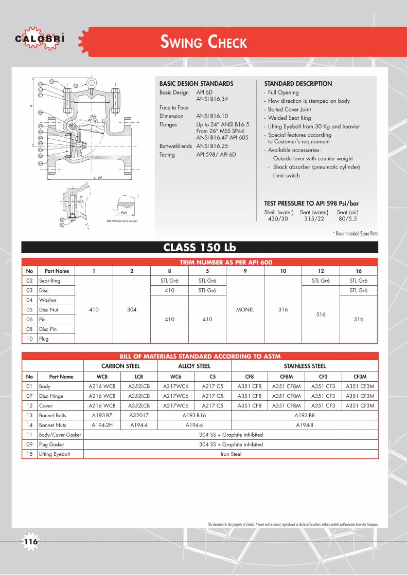
This document is the property of Calobri. It must not be stored, reproduced or disclosed to others without written authorisation from the Company.
SWING CHECK
CLASS 150 LbTRIM NUMBER AS PER API 600
No Part Name 1 2 8 5 9 10 12 16
02 Seat Ring
410 304
STL Gr6 STL Gr6
MONEL 316
STL Gr6 STL Gr6
03 Disc 410 STL Gr6
316
STL Gr6
04 Washer
410 410 316
05 Disc Nut
06 Pin
08 Disc Pin
10 Plug
BILL OF MATERIALS STANDARD ACCORDING TO ASTM
CARBON STEEL ALLOY STEEL STAINLESS STEEL
No Part Name WCB LCB WC6 C5 CF8 CF8M CF3 CF3M
01 Body A216 WCB A352LCB A217WC6 A217 C5 A351 CF8 A351 CF8M A351 CF3 A351 CF3M
07 Disc Hinge A216 WCB A352LCB A217WC6 A217 C5 A351 CF8 A351 CF8M A351 CF3 A351 CF3M
12 Cover A216 WCB A352LCB A217WC6 A217 C5 A351 CF8 A351 CF8M A351 CF3 A351 CF3M
13 Bonnet Bolts A193-B7 A320-L7 A193-B16 A193-B8
14 Bonnet Nuts A194-2H A194-4 A194-4 A194-8
11 Body/Cover Gasket 304 SS + Graphite inhibited
09 Plug Gasket 304 SS + Graphite inhibited
15 Lifting Eyebolt Iron Steel
BASIC DESIGN STANDARDSBasic Design API 6D ANSI B16.34Face to FaceDimension ANSI B16.10Flanges Up to 24” ANSI B16.5 From 26” MSS SP44 ANSI B16.47 API 605Butt-weld ends ANSI B16.25Testing API 598/ API 6D
STANDARD DESCRIPTION- Full Opening- Flow direction is stamped on body- Bolted Cover Joint- Welded Seat Ring- Lifting Eyebolt from 30 Kg and heavier- Special features according
to Customer’s requirement- Available accessories: - Outside lever with counter weight - Shock absorber (pneumatic cylinder) - Limit switch
TEST PRESSURE TO API 598 Psi/bar Shell (water) Seat (water) Seat (air) 430/30 315/22 80/5.5
L - BW
BW Welded-End version*
*
L - RF
01
H
02
03
04
06
05
07
08
11
12
1413
15
10
09
* Recommended Spare Parts
116

CLASS 800
This document is the property of Calobri. It must not be stored, reproduced or disclosed to others without written authorisation from the Company.
SWING CHECK
CLASS 150 Lb
TEMP. WORKING PRESSURE (BAR.G)
°C Carbon Steel Alloy Steel Stainless SteelWCB (a)
LCB (b)
WC6 (c)
WC9 (c)
C5 (g)
C12 (g)
CF8 (d)
CF8M (d)
CF3 (e)
CF3M (f)
-29 to 38 19.6 18.4 19.8 19.8 20 20 19 19 19 19
50 19.2 18.2 19.5 19.5 19.5 19.5 18.3 18.4 18.3 18.4
100 17.7 17.4 17.7 17.7 17.7 17.7 15.7 16.2 15.7 16.2
150 15.8 15.8 15.8 15.8 15.8 15.8 14.2 14.8 14.2 14.8
200 13.8 13.8 13.8 13.8 13.8 13.8 13.2 13.7 13.2 13.7
250 12.1 12.1 12.1 12.1 12.1 12.1 12.1 12.1 12.1 12.1
300 10.2 10.2 10.2 10.2 10.2 10.2 10.2 10.2 10.2 10.2
350 8.4 8.4 8.4 8.4 8.4 8.4 8.4 8.4 8.4 8.4
400 6.5 6.5 6.5 6.5 6.5 6.5 6.5 6.5 6.5 6.5
425 5.5 5.5 5.5 5.5 5.5 5.5 5.5 5.5 5.5 5.5
450 4.6 4.6 4.6 4.6 4.6 4.6 4.6 4.6 4.6 4.6
500 2.8 2.8 2.8 2.8 2.8 2.8 2.8 2.8 2.8 2.8
538 1.4 1.4 1.4 1.4 1.4 1.4 1.4 1.4 1.4 1.4
550 - - 1.4 1.4 1.4 1.4 1.4 1.4 1.4 1.4
600 - - 1.4 1.4 1.4 1.4 1.4 1.4 1.4 1.4
650 - - - - - - 1.4 1.4 1.4 1.4
700 - - - - - - 1.4 1.4 1.4 1.4
750 - - - - - - 1.4 1.4 1.4 1.4
800 - - - - - - - - - -
(a) Permissible, but not recommended for prolonged usage above 425 °C(b) Not be used over 345 °C.(c) Permissible, but not recommended for prolonged usage above 595 °C Flanged End valve ratings terminate at 538°C.(d) At temperature above 538 °C, use only when carbon content is 0.04 % or higher. Flanged End valve ratings terminate at 538°C(e) Not be used over 425 °C. Flanged End valve ratings terminate at 538°C.(f) Not be used over 455 °C. Flanged End valve ratings terminate at 538°C.(g) Flanged End valve ratings terminate at 538°C.
ANSI CLASS 150 PRESSURE - TEMPERATURE RATINGS TO ANSI B16.34
SIZE DIMENSION IN mm WEIGHTInches mm L(RF) L(BW) H Kg
2” 50 203 203 150 19
3” 80 241 241 175 29
4” 100 292 292 210 49
6” 150 356 356 315 77
8” 200 495 495 365 140
10” 250 622 622 445 207
12” 300 698 698 520 330
14” 350 787 787 600 410
16” 400 864 864 615 600
18” 450 978 978 655 680
20” 500 978 978 670 750
22” 550 1067 1067 725
24” 600 1295 1295 765 1280
117

This document is the property of Calobri. It must not be stored, reproduced or disclosed to others without written authorisation from the Company.
SWING CHECK
CLASS 300 LbTRIM NUMBER AS PER API 600
No Part Name 1 2 8 5 9 10 12 16
02 Seat Ring
410 304
STL Gr6 STL Gr6
MONEL 316
STL Gr6 STL Gr6
03 Disc 410 STL Gr6
316
STL Gr6
04 Washer
410 410 316
05 Disc Nut
06 Pin
08 Disc Pin
10 Plug
BILL OF MATERIALS STANDARD ACCORDING TO ASTM
CARBON STEEL ALLOY STEEL STAINLESS STEEL
No Part Name WCB LCB WC6 C5 CF8 CF8M CF3 CF3M
01 Body A216 WCB A352LCB A217WC6 A217 C5 A351 CF8 A351 CF8M A351 CF3 A351 CF3M
07 Disc Hinge A216 WCB A352LCB A217WC6 A217 C5 A351 CF8 A351 CF8M A351 CF3 A351 CF3M
12 Cover A216 WCB A352LCB A217WC6 A217 C5 A351 CF8 A351 CF8M A351 CF3 A351 CF3M
13 Bonnet Bolts A193-B7 A320-L7 A193-B16 A193-B8
14 Bonnet Nuts A194-2H A194-4 A194-4 A194-8
11 Body/Cover Gasket 304 SS + Graphite inhibited
09 Plug Gasket 304 SS + Graphite inhibited
15 Lifting Eyebolt Iron Steel
BASIC DESIGN STANDARDSBasic Design API 6D ANSI B16.34Face to FaceDimension ANSI B16.10Flanges Up to 24” ANSI B16.5 From 26” MSS SP44 ANSI B16.47 API 605Butt-weld ends ANSI B16.25Testing API 598/ API 6D
STANDARD DESCRIPTION- Full Opening- Flow direction is stamped on body- Bolted Cover Joint- Welded Seat Ring- Lifting Eyebolt from 30 Kg and heavier- Special features according
to Customer’s requirement- Available accessories: - Outside lever with counter weight - Shock absorber (pneumatic cylinder) - Limit switch
TEST PRESSURE TO API 598 Psi/bar Shell (water) Seat (water) Seat (air) 1100/76 800/55 80/5.5
L - BW
BW Welded-End version*
*
L - RF
01
H
02
03
04
06
05
07
08
11
12
1413
15
10
09
* Recommended Spare Parts
118
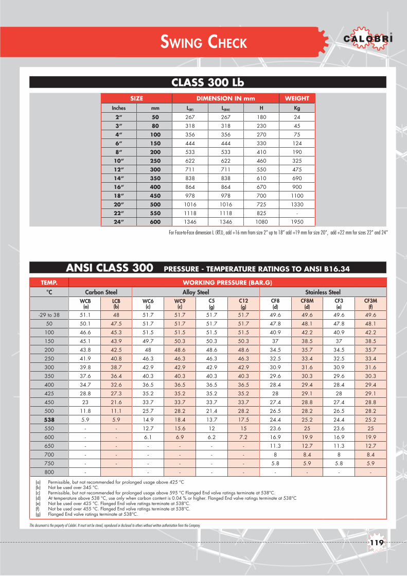
CLASS 800
This document is the property of Calobri. It must not be stored, reproduced or disclosed to others without written authorisation from the Company.
SWING CHECK
CLASS 300 Lb
TEMP. WORKING PRESSURE (BAR.G)
°C Carbon Steel Alloy Steel Stainless SteelWCB (a)
LCB (b)
WC6 (c)
WC9 (c)
C5 (g)
C12 (g)
CF8 (d)
CF8M (d)
CF3 (e)
CF3M (f)
-29 to 38 51.1 48 51.7 51.7 51.7 51.7 49.6 49.6 49.6 49.6
50 50.1 47.5 51.7 51.7 51.7 51.7 47.8 48.1 47.8 48.1
100 46.6 45.3 51.5 51.5 51.5 51.5 40.9 42.2 40.9 42.2
150 45.1 43.9 49.7 50.3 50.3 50.3 37 38.5 37 38.5
200 43.8 42.5 48 48.6 48.6 48.6 34.5 35.7 34.5 35.7
250 41.9 40.8 46.3 46.3 46.3 46.3 32.5 33.4 32.5 33.4
300 39.8 38.7 42.9 42.9 42.9 42.9 30.9 31.6 30.9 31.6
350 37.6 36.4 40.3 40.3 40.3 40.3 29.6 30.3 29.6 30.3
400 34.7 32.6 36.5 36.5 36.5 36.5 28.4 29.4 28.4 29.4
425 28.8 27.3 35.2 35.2 35.2 35.2 28 29.1 28 29.1
450 23 21.6 33.7 33.7 33.7 33.7 27.4 28.8 27.4 28.8
500 11.8 11.1 25.7 28.2 21.4 28.2 26.5 28.2 26.5 28.2
538 5.9 5.9 14.9 18.4 13.7 17.5 24.4 25.2 24.4 25.2
550 - - 12.7 15.6 12 15 23.6 25 23.6 25
600 - - 6.1 6.9 6.2 7.2 16.9 19.9 16.9 19.9
650 - - - - - - 11.3 12.7 11.3 12.7
700 - - - - - - 8 8.4 8 8.4
750 - - - - - - 5.8 5.9 5.8 5.9
800 - - - - - - - - -
(a) Permissible, but not recommended for prolonged usage above 425 °C(b) Not be used over 345 °C.(c) Permissible, but not recommended for prolonged usage above 595 °C Flanged End valve ratings terminate at 538°C.(d) At temperature above 538 °C, use only when carbon content is 0.04 % or higher. Flanged End valve ratings terminate at 538°C(e) Not be used over 425 °C. Flanged End valve ratings terminate at 538°C.(f) Not be used over 455 °C. Flanged End valve ratings terminate at 538°C.(g) Flanged End valve ratings terminate at 538°C.
ANSI CLASS 300 PRESSURE - TEMPERATURE RATINGS TO ANSI B16.34
SIZE DIMENSION IN mm WEIGHTInches mm L(RF) L(BW) H Kg
2” 50 267 267 180 24
3” 80 318 318 230 45
4” 100 356 356 270 75
6” 150 444 444 330 124
8” 200 533 533 410 190
10” 250 622 622 460 325
12” 300 711 711 550 475
14” 350 838 838 610 690
16” 400 864 864 670 900
18” 450 978 978 700 1100
20” 500 1016 1016 725 1330
22” 550 1118 1118 825 -
24” 600 1346 1346 1080 1950
For Face-to-Face dimension L (RTJ), add +16 mm from size 2” up to 18” add +19 mm for size 20”, add +22 mm for sizes 22” and 24”
119

This document is the property of Calobri. It must not be stored, reproduced or disclosed to others without written authorisation from the Company.
SWING CHECK
CLASS 600 LbTRIM NUMBER AS PER API 600
No Part Name 1 2 8 5 9 10 12 16
02 Seat Ring
410 304
STL Gr6 STL Gr6
MONEL 316
STL Gr6 STL Gr6
03 Disc 410 STL Gr6
316
STL Gr6
04 Washer
410 410 316
05 Disc Nut
06 Pin
08 Disc Pin
10 Plug
BILL OF MATERIALS STANDARD ACCORDING TO ASTM
CARBON STEEL ALLOY STEEL STAINLESS STEEL
No Part Name WCB LCB WC6 C5 CF8 CF8M CF3 CF3M
01 Body A216 WCB A352LCB A217WC6 A217 C5 A351 CF8 A351 CF8M A351 CF3 A351 CF3M
07 Disc Hinge A216 WCB A352LCB A217WC6 A217 C5 A351 CF8 A351 CF8M A351 CF3 A351 CF3M
12 Cover A216 WCB A352LCB A217WC6 A217 C5 A351 CF8 A351 CF8M A351 CF3 A351 CF3M
13 Bonnet Bolts A193-B7 A320-L7 A193-B16 A193-B8
14 Bonnet Nuts A194-2H A194-4 A194-4 A194-8
11 Body/Cover Gasket 304 SS + Graphite inhibited
09 Plug Gasket 304 SS + Graphite inhibited
15 Lifting Eyebolt Iron Steel
BASIC DESIGN STANDARDSBasic Design API 6D ANSI B16.34Face to FaceDimension ANSI B16.10Flanges Up to 24” ANSI B16.5 From 26” MSS SP44 ANSI B16.47 API 605Butt-weld ends ANSI B16.25Testing API 598/ API 6D
STANDARD DESCRIPTION- Full Opening- Flow direction is stamped on body- Bolted Cover Joint- Welded Seat Ring- Lifting Eyebolt from 30 Kg and heavier- Special features according
to Customer’s requirement- Available accessories: - Outside lever with counter weight - Shock absorber (pneumatic cylinder) - Limit switch
TEST PRESSURE TO API 598 Psi/bar Shell (water) Seat (water) Seat (air) 2175/150 1600/110 80/5.5L - BW
BW Welded-End version
*
*
L - RF
01
H
02
03
04
06
05
07
08
11
12
1413
15
10
09
L - RTJ
ØP
ØN
RTJ Flanged-End version
* Recommended Spare Parts
120

CLASS 800
This document is the property of Calobri. It must not be stored, reproduced or disclosed to others without written authorisation from the Company.
SWING CHECK
CLASS 600 Lb
TEMP. WORKING PRESSURE (BAR.G)
°C Carbon Steel Alloy Steel Stainless SteelWCB (a)
LCB (b)
WC6 (c)
WC9 (c)
C5 (g)
C12 (g)
CF8 (d)
CF8M (d)
CF3 (e)
CF3M (f)
-29 to 38 102.1 96 103.4 103.4 103.4 103.4 99.3 99.3 99.3 99.3
50 100.2 94.9 103.4 103.4 103.4 103.4 95.6 96.2 95.6 96.2
100 93.2 90.7 103 103 103 103 81.7 84.4 81.7 84.4
150 90.2 87.9 99.5 100.3 100.3 100.3 74 77 74 77
200 87.6 85.1 95.9 97.2 97.2 97.2 69 71.3 69 71.3
250 83.9 81.6 92.7 92.7 92.7 92.7 65 66.8 65 66.8
300 79.6 77.4 85.7 85.7 85.7 85.7 61.8 63.2 61.8 63.2
350 75.1 72.8 80.4 80.4 80.4 80.4 59.3 60.7 59.3 60.7
400 69.4 65.2 73.3 73.3 73.3 73.3 56.9 58.9 56.9 58.9
425 57.5 54.6 70 70 70 70 56 58.3 56 58.3
450 46 43.2 67.7 67.7 67.7 67.7 54.8 57.7 54.8 57.7
500 23.5 22.1 51.5 56.5 42.8 56.5 53 56.5 53 56.5
538 11.8 11.8 29.8 36.9 27.4 35 48.9 50 48.9 50
550 - - 25.4 31.3 24.1 30 47.1 49.8 47.1 49.8
600 - - 12.2 13.8 12.5 14.4 33.8 39.8 33.8 39.8
650 - - - - - - 22.5 25.3 22.5 25.3
700 - - - - - - 16.1 16.8 16.1 16.8
750 - - - - - - 11.6 11.7 11.6 11.7
800 - - - - - - - - - -
(a) Permissible, but not recommended for prolonged usage above 425 °C(b) Not be used over 345 °C.(c) Permissible, but not recommended for prolonged usage above 595 °C Flanged End valve ratings terminate at 538°C.(d) At temperature above 538 °C, use only when carbon content is 0.04 % or higher. Flanged End valve ratings terminate at 538°C(e) Not be used over 425 °C. Flanged End valve ratings terminate at 538°C.(f) Not be used over 455 °C. Flanged End valve ratings terminate at 538°C.(g) Flanged End valve ratings terminate at 538°C.
ANSI CLASS 600 PRESSURE - TEMPERATURE RATINGS TO ANSI B16.34
SIZE DIMENSION IN mm WEIGHTInches mm L(RF) L(BW) H Kg
2” 50 292 292 230 40
3” 80 356 356 270 60
4” 100 432 432 310 103
6” 150 559 559 400 230
8” 200 660 660 460 355
10” 250 787 787 580 627
12” 300 838 838 620 790
14” 350 889 889 660 820
16” 400 991 991 710 1400
18” 450 1092 1092 765 1800
20” 500 1194 1194 885 2300
22” 550 1295 1295 - -
24” 600 1397 1397 1020 3330
For Face-to-Face dimension L (RTJ), add +3 mm from size 2” up to 18” add +6 mm for size 20”, add +10 mm for sizes 22” and 24”
121

122

85
TECHNICAL DATA
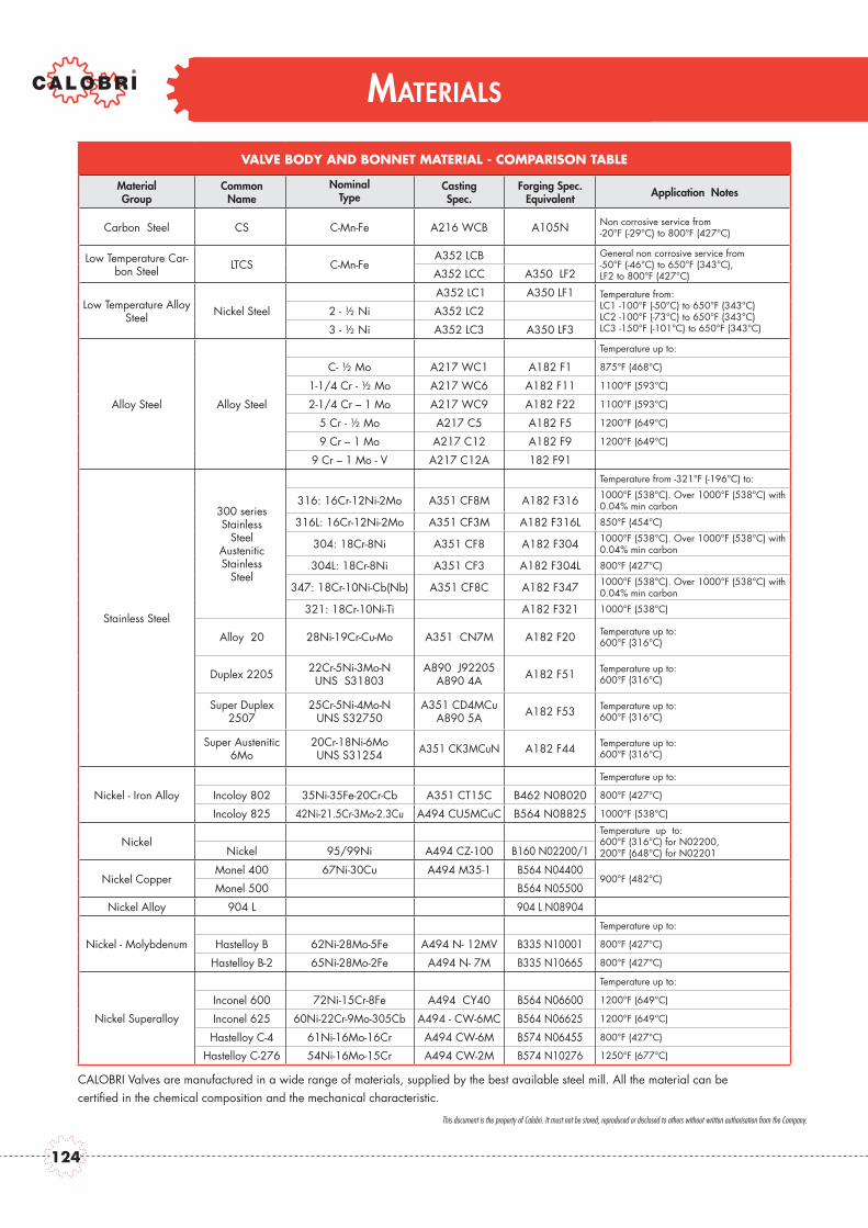
MATERIALS
VALVE BODY AND BONNET MATERIAL - COMPARISON TABLE
MaterialGroup
Common Name
NominalType
CastingSpec.
Forging Spec. Equivalent Application Notes
Carbon Steel CS C-Mn-Fe A216 WCB A105N Non corrosive service from-20°F (-29°C) to 800°F (427°C)
Low Temperature Car-bon Steel LTCS C-Mn-Fe
A352 LCB General non corrosive service from-50°F (-46°C) to 650°F (343°C),LF2 to 800°F (427°C)A352 LCC A350 LF2
Low Temperature Alloy Steel Nickel Steel
A352 LC1 A350 LF1 Temperature from:LC1 -100°F (-50°C) to 650°F (343°C)LC2 -100°F (-73°C) to 650°F (343°C)LC3 -150°F (-101°C) to 650°F (343°C)
2 - ½ Ni A352 LC2
3 - ½ Ni A352 LC3 A350 LF3
Alloy Steel Alloy Steel
Temperature up to:
C- ½ Mo A217 WC1 A182 F1 875°F (468°C)
1-1/4 Cr - ½ Mo A217 WC6 A182 F11 1100°F (593°C)
2-1/4 Cr – 1 Mo A217 WC9 A182 F22 1100°F (593°C)
5 Cr - ½ Mo A217 C5 A182 F5 1200°F (649°C)
9 Cr – 1 Mo A217 C12 A182 F9 1200°F (649°C)
9 Cr – 1 Mo - V A217 C12A 182 F91
Stainless Steel
300 series Stainless
Steel Austenitic Stainless
Steel
Temperature from -321°F (-196°C) to:
316: 16Cr-12Ni-2Mo A351 CF8M A182 F316 1000°F (538°C). Over 1000°F (538°C) with 0.04% min carbon
316L: 16Cr-12Ni-2Mo A351 CF3M A182 F316L 850°F (454°C)
304: 18Cr-8Ni A351 CF8 A182 F304 1000°F (538°C). Over 1000°F (538°C) with 0.04% min carbon
304L: 18Cr-8Ni A351 CF3 A182 F304L 800°F (427°C)
347: 18Cr-10Ni-Cb(Nb) A351 CF8C A182 F347 1000°F (538°C). Over 1000°F (538°C) with 0.04% min carbon
321: 18Cr-10Ni-Ti A182 F321 1000°F (538°C)
Alloy 20 28Ni-19Cr-Cu-Mo A351 CN7M A182 F20 Temperature up to: 600°F (316°C)
Duplex 2205 22Cr-5Ni-3Mo-N UNS S31803
A890 J92205 A890 4A A182 F51 Temperature up to:
600°F (316°C)
Super Duplex 2507
25Cr-5Ni-4Mo-N UNS S32750
A351 CD4MCu A890 5A A182 F53 Temperature up to:
600°F (316°C)
Super Austenitic 6Mo
20Cr-18Ni-6Mo UNS S31254 A351 CK3MCuN A182 F44 Temperature up to:
600°F (316°C)
Nickel - Iron Alloy
Temperature up to:
Incoloy 802 35Ni-35Fe-20Cr-Cb A351 CT15C B462 N08020 800°F (427°C)
Incoloy 825 42Ni-21.5Cr-3Mo-2.3Cu A494 CU5MCuC B564 N08825 1000°F (538°C)
NickelTemperature up to:600°F (316°C) for N02200, 200°F (648°C) for N02201 Nickel 95/99Ni A494 CZ-100 B160 N02200/1
Nickel CopperMonel 400 67Ni-30Cu A494 M35-1 B564 N04400
900°F (482°C)Monel 500 B564 N05500
Nickel Alloy 904 L 904 L N08904
Nickel - Molybdenum
Temperature up to:
Hastelloy B 62Ni-28Mo-5Fe A494 N- 12MV B335 N10001 800°F (427°C)
Hastelloy B-2 65Ni-28Mo-2Fe A494 N- 7M B335 N10665 800°F (427°C)
Nickel Superalloy
Temperature up to:
Inconel 600 72Ni-15Cr-8Fe A494 CY40 B564 N06600 1200°F (649°C)
Inconel 625 60Ni-22Cr-9Mo-305Cb A494 - CW-6MC B564 N06625 1200°F (649°C)
Hastelloy C-4 61Ni-16Mo-16Cr A494 CW-6M B574 N06455 800°F (427°C)
Hastelloy C-276 54Ni-16Mo-15Cr A494 CW-2M B574 N10276 1250°F (677°C)
CALOBRI Valves are manufactured in a wide range of materials, supplied by the best available steel mill. All the material can becertified in the chemical composition and the mechanical characteristic.
This document is the property of Calobri. It must not be stored, reproduced or disclosed to others without written authorisation from the Company.
124

MATERIALS
CALOBRI TRIM STANDARD DEFINITION
Trim Nr. Seat Ring Wedge / Disc Stem & Backseat Gland
1 13% Cr 13% Cr 13% Cr 13% Cr
2 304 304 304 304
8 Stellite 13% Cr 13% Cr 13% Cr
5 Stellite Stellite 13% Cr 13% Cr
10 316 316 316 316
12 Stellite 316 316 316
16 316 + Stellite 316 + Stellite 316 316
DESIGN AND MANUFACTURING STANDARDS
Reference Title
EN 10204 Metallic products - Type of inspection documents
NACE MR01-75 / ISO 15156 Petroleum and natural gas industries - Materials for use in H2Scontaining environments in oil and gas production
MSS SP 25 Standard Marking System for Valves, Fittings, Flanges and Unions
MSS SP 45 By-pass and Drain Connections
MSS SP 54 Quality Standards for Steel Castings for Valves, Flanges, and Fittings and Other Piping Components – Radiographic Examination Method
MSS SP 55 Quality Standards for Steel Castings for Valves, Flanges, and Fittings and Other Piping Components - Visual Inspection
ASME B 16.5 Pipe Flanges and Flanged Fittings
ASME B16.10 Face-to-Face and End-to-End Dimension of Ferrous Valves
ASME B 16.25 Buttwelding Ends
ASME B 16.34 Valves-Flanged, Threaded, and Welding End
ASME B 16.47 Large Diameter Steel Flanges (NPS 26 through NPS 60)
ASTM A 216 Carbon Steel Castings Suitable for Fusion Welding for High-Temperature Service
ASTM A 217 Martensitic Stainless Steel and Alloy Steel Castings for Pressure Containing Parts Suitable for High Temperature Service
ASTM A 351 Austenitic Steel Castings for High Temperature Service
ASTM A 352 Ferritic Steel Castings for Pressure Containing Parts Suitable for Low Temperature Service
API 6D / ISO 10413 Specification for Pipeline Valves (Gate, Plug, Ball, and Check Valves)
API 598 Valve Inspection and Testing
API 600 / ISO 10434 Steel Gate Valves Flanged and Butt welding Ends
BS 1873 Steel Globe and Globe Stop and check Valves ( Flanged and buut welding ends for the Petroleum )
97/23/EC Pressure Equipment Directive
94/9/EC Equipment for use in potentially explosive atmospheres
ASME V Non-destructive Examination
ASME VIII division 1 Rules for Construction of Pressure Vessels
ASME Section IX Welding and brazing qualifications
The following tables shown main Standard combination of Body and Bonnet or Cover materials and Trim (stem, disc or wedge, seat, gland) composition. Different combinations are available upon request.
Note: These charts are for reference only. CALOBRI recommends Customer Engineers to analyse service requirements and specify the materials they consider optimum. CALOBRI can not be held liable for any damage occurred due to the use of the table.
This document is the property of Calobri. It must not be stored, reproduced or disclosed to others without written authorisation from the Company.
125
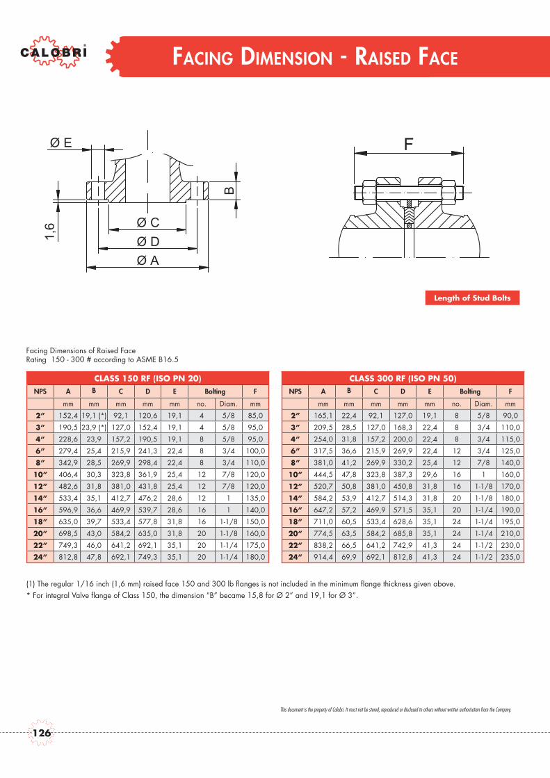
FACING DIMENSION - RAISED FACE
CLASS 150 RF (ISO PN 20)NPS A B C D E Bolting F
mm mm mm mm mm no. Diam. mm
2” 152,4 19,1 (*) 92,1 120,6 19,1 4 5/8 85,0
3” 190,5 23,9 (*) 127,0 152,4 19,1 4 5/8 95,0
4” 228,6 23,9 157,2 190,5 19,1 8 5/8 95,0
6” 279,4 25,4 215,9 241,3 22,4 8 3/4 100,0
8” 342,9 28,5 269,9 298,4 22,4 8 3/4 110,0
10” 406,4 30,3 323,8 361,9 25,4 12 7/8 120,0
12” 482,6 31,8 381,0 431,8 25,4 12 7/8 120,0
14” 533,4 35,1 412,7 476,2 28,6 12 1 135,0
16” 596,9 36,6 469,9 539,7 28,6 16 1 140,0
18” 635,0 39,7 533,4 577,8 31,8 16 1-1/8 150,0
20” 698,5 43,0 584,2 635,0 31,8 20 1-1/8 160,0
22” 749,3 46,0 641,2 692,1 35,1 20 1-1/4 175,0
24” 812,8 47,8 692,1 749,3 35,1 20 1-1/4 180,0
CLASS 300 RF (ISO PN 50)NPS A B C D E Bolting F
mm mm mm mm mm no. Diam. mm
2” 165,1 22,4 92,1 127,0 19,1 8 5/8 90,0
3” 209,5 28,5 127,0 168,3 22,4 8 3/4 110,0
4” 254,0 31,8 157,2 200,0 22,4 8 3/4 115,0
6” 317,5 36,6 215,9 269,9 22,4 12 3/4 125,0
8” 381,0 41,2 269,9 330,2 25,4 12 7/8 140,0
10” 444,5 47,8 323,8 387,3 29,6 16 1 160,0
12” 520,7 50,8 381,0 450,8 31,8 16 1-1/8 170,0
14” 584,2 53,9 412,7 514,3 31,8 20 1-1/8 180,0
16” 647,2 57,2 469,9 571,5 35,1 20 1-1/4 190,0
18” 711,0 60,5 533,4 628,6 35,1 24 1-1/4 195,0
20” 774,5 63,5 584,2 685,8 35,1 24 1-1/4 210,0
22” 838,2 66,5 641,2 742,9 41,3 24 1-1/2 230,0
24” 914,4 69,9 692,1 812,8 41,3 24 1-1/2 235,0
Ø E
BØ CØ DØ A
1,6
F
Facing Dimensions of Raised Face Rating 150 - 300 # according to ASME B16.5
Length of Stud Bolts
(1) The regular 1/16 inch (1,6 mm) raised face 150 and 300 lb flanges is not included in the minimum flange thickness given above.* For integral Valve flange of Class 150, the dimension “B” became 15,8 for Ø 2” and 19,1 for Ø 3”.
This document is the property of Calobri. It must not be stored, reproduced or disclosed to others without written authorisation from the Company.
126

FACING DIMENSION - RAISED FACE
CLASS 600 RF (ISO PN 110)NPS A B C D E Bolting F
mm mm mm mm mm no. Diam. mm
2” 165,1 25,4 92,1 127,0 19,1 8 5/8 110,0
3” 209,6 31,8 127,0 168,3 22,4 8 3/4 125,0
4” 273,0 38,1 157,2 215,9 25,4 8 7/8 145,0
6” 355,6 47,8 215,9 292,1 28,6 12 1 170,0
8” 419,1 55,7 269,9 349,2 31,8 12 1-1/8 195,0
10” 508,0 63,5 323,8 431,8 35,1 16 1-1/4 215,0
12” 558,8 66,6 381,0 488,9 35,1 20 1-1/4 220,0
14” 603,2 69,9 412,7 527,0 38,1 20 1-3/8 235,0
16” 685,8 76,2 469,9 603,2 41,3 20 1-1/2 255,0
18” 742,9 82,6 533,4 654,0 44,5 20 1-5/8 275,0
20” 812,8 88,9 584,2 723,9 44,5 24 1-5/8 290,0
22” 869,9 95,3 641,2 777,9 47,8 24 1-3/4 310,0
24” 939,8 101,6 692,1 838,2 50,8 24 1-7/8 330,0
CLASS 900 RF (ISO PN 150)NPS A B C D E Bolting F
mm mm mm mm mm no. Diam. mm
2” 216,0 38,1 92,1 165,1 25,4 8 7/8 145,0
3” 241,3 38,1 127,0 190,5 25,4 8 7/8 145,0
4” 292,0 44,5 157,2 235,0 31,8 8 1-1/8 170,0
6” 381,0 55,7 215,9 317,5 31,8 12 1-1/8 195,0
8” 470,0 63,5 269,9 393,7 38,1 12 1-3/8 220,0
10” 546,0 69,9 323,8 469,9 38,1 16 1-3/8 235,0
12” 609,5 79,3 381,0 533,4 38,1 20 1-3/8 255,0
14” 641,5 85,9 412,7 558,8 41,3 20 1-1/2 275,0
16” 705,0 88,9 469,9 616,0 45,0 20 1-5/8 265,0
18” 787,5 101,6 533,4 685,8 51,0 20 1-7/8 325,0
20” 857,5 108,0 584,2 749,3 54,0 20 2 345,0
22” - - - - - - - -
24” 1041,5 139,7 692,1 901,7 66,5 20 2-1/2 440,0
6,4
Ø AØ DØ C
B
Ø E F
Facing Dimensions of Raised FaceRating 600 - 900 # according to ASME B16.5
Length of Stud Bolts
The regular 1/4 inch (6,4 mm) raised face of 600 and 900 Lbs flanges is not included in the minimum flange thickness given above.
This document is the property of Calobri. It must not be stored, reproduced or disclosed to others without written authorisation from the Company.
127

FACING DIMENSION - RING JOINT
RATING 150 LbsNPS RJ P F G E R
2” R22 82,5 8,7 101,6 6,4 0,8
3” R29 114,3 8,7 133,3 6,4 0,8
4” R36 149,2 8,7 171,4 6,4 0,8
6” R43 193,7 8,7 219,1 6,4 0,8
8” R48 247,6 8,7 273 6,4 0,8
10” R52 304,8 8,7 330,2 6,4 0,8
12” R56 381 8,7 406,4 6,4 0,8
14” R59 396,9 8,7 425,4 6,4 0,8
16” R64 454 8,7 482,6 6,4 0,8
18” R68 517,5 8,7 546,1 6,4 0,8
20” R72 558,8 8,7 596,9 6,4 0,8
22” R80 615,9 8,7 647,7 6,4 0,8
24” R76 673,1 8,7 711,2 6,4 0,8
RATING 900 LbsNPS RJ P F G E R
2” R24 95,2 11,9 123,8 7,9 0,8
3” R31 123,8 11,9 155,6 7,9 0,8
4” R37 149,2 11,9 181 7,9 0,8
6” R45 211,1 11,9 241,3 7,9 0,8
8” R49 269,9 11,9 308 7,9 0,8
10” R53 323,8 11,9 361,9 7,9 0,8
12” R57 381 11,9 419,1 7,9 0,8
14” R62 419,9 16,7 466,7 11,1 1,6
16” R66 469,9 16,7 523,9 11,1 1,6
18” R70 533,4 19,8 593,7 12,7 1,6
20” R74 584,2 19,8 647,7 12,7 1,6
24” R78 691,1 27 771,5 15,9 2,4
RATING 300 - 600 LbsNPS RJ P F G E R
2” R23 82,5 11,9 107,9 7,9 0,8
3” R31 123,8 11,9 146 7,9 0,8
4” R37 149,2 11,9 174,6 7,9 0,8
6” R45 211,1 11,9 241,3 7,9 0,8
8” R49 269,9 11,9 301,6 7,9 0,8
10” R53 323,8 11,9 355,6 7,9 0,8
12” R57 381 11,9 412,7 7,9 0,8
14” R61 419,1 11,9 457,2 7,9 0,8
16” R65 469,9 11,9 508 7,9 0,8
18” R69 533,4 11,9 574,7 7,9 0,8
20” R73 584,2 13,5 635 9,5 1,6
22” R81 635 15,1 685,8 11,1 1,6
24” R77 692,1 16,7 749,3 11,1 1,6
RATING 300 - 600 LbsNPS RJ P F G E R
2” R24 95,2 11,9 123,8 7,9 0,8
3” R35 136,5 11,9 168,5 7,9 0,8
4” R39 161,9 11,9 193,7 7,9 0,8
6” R46 211,1 13,5 247,6 9,5 1,6
8” R50 269,9 16,7 317,5 11,1 1,6
10” R54 323,8 16,7 371,5 11,1 1,6
12” R58 881 23 438,1 14,3 1,6
14” R63 419,1 27 488,9 15,9 2,4
16” R67 469,9 30,2 546,1 17,5 2,4
18” R71 533,4 30,2 612,8 17,5 2,4
20” R75 584,2 33,3 673,1 17,5 2,4
24” R79 692,1 36,5 793,7 20,6 2,4
R
23°
E
F
E
Q
Ø G
Ø P
TOLERANCES
Dim. E = + 0,40
Dim. F = ± 0,20
Dim. P = ± 0,150
Dim. Q = + 0,40
23° = ± 1/2°
R ≤ 1,6 + 0,8
R > 1,6 ± 0,8
Facing Dimensions of Ring Joint GroovesRating 150 - 300 - 600 – 900 – 1500 # according to ASME B16.5
This document is the property of Calobri. It must not be stored, reproduced or disclosed to others without written authorisation from the Company.
128

NOTE
129

NOTE
130
BALL VALVES

mm in. mm in. mm in. mm in. mm in. mm in. mm in. mm in. mm in. mm in.- - 368 14.48 470 18.50 546 21.49 705 27.75 832 32.75 991 39.01 1130 44.48 1257 49.5 1384 54.5
384 15.11 451 17.75 578 22.75 673 26.49 914 35.98 - - - - - - - - - -- - 190 7.48 205 8.07 210 8.26 245 9.64 335 13.18 410 16.14 465 18.30 553 21.77 626 24.64
185 7.28 200 7.87 215 8.46 220 8.66 255 10.03 - - - - - - - - - -- - 110 4.33 120 4.72 125 4.92 160 6.29 255 10.03 290 11.41 335 13.18 438 17.24 498 19.6
105 4.13 120 4.72 130 5.11 135 5.31 170 6.69 - - - - - - - - - -
REDUCED BOREDN 50x40 80x50 100x80 150x100 200x150 250x200 300x250 350x300 400x350 450x400 500x450 600x550
IN 2”x11/2” 3”x2” 4”x3” 6”x4” 8”x6” 10”x8” 12”x10” 14”x12 16”x14” 18”x16” 20”x18” 24”x20”
REDUCED BOREDN 40X25 50X40 80X50 100X80 150X100 200X150 250X200 300X250 350x300 400x350
IN 11/2”x1 2”x1.1/2” 3”x2” 4”x3” 6”x4” 8”x6” 10”x8” 12”x10” 14”x12” 16”x14”
RATINGS: Carbon Steel Class 1500-3600 p.s.i. @ 100°F-Seat NylonClass 2500-6000 p.s.i. @ 100°F-Seat Nylon
BSE Class 1500BSE Class 2500Center Class 1500to Top Class 2500Center Class 1500to Bottom Class 2500
CLASS 1500-2500 REDUCED BORE - TRUNNION MOUNTED SIDE ENTRY BALL VALVESIntegral Flanges - End to End According to API 6D Flange dimensions to ANSI B16.5
AABBCC
mm20328335638114020035620090
120110120
mm229305432458190240240240105130110130
mm394403559610280280280280166150175175
mm457502660737295295305350175175195220
mm533568787839330330400390210210280260
mm610648838966400420435480250270285310
mm686762889
1029460465440438310325320410
mm762838991
1131480545505545340430340370
mm86491410921220540600590650385470410420
mm91499111941321580620700675428510445617
mm1067114313971549715734775790545500510725
BSE Class 150BSE Class 300BSE Class 600BSE Class 900
Class 150Center Class 300to Top Class 600
Class 900Class 150
Center Class 300to Bottom Class 600
Class 900
mm-
216292369
-175190155
-8090
108
in.-
8.5011.4914.52
-6.887.486.10
-3.143.544.25
CLASS 150-300-600-900 REDUCED BORE-TRUNNION MOUNTED SIDE ENTRY BALL VALVESIntegral flanges - End to End According to API 6D Flange Dimensions to ANSI B16.5
WITH LEVER WITH GEAR
in.7.99
11.1414.0115.005.517.87
14.017.873.544.724.334.72
in.9.0112.0017.0018.037.489.449.449.444.135.114.335.11
in.15.5115.8622.0024.0111.0211.0211.0211.026.535.906.886.88
in.17.9919.7625.9829.0111.6111.6112.0013.776.886.887.678.66
in.20.9822.3630.9833.0312.9912.9915.7415.358.268.2611.0210.23
in.24.0125.5132.9938.0315.7416.5317.1218.899.84
10.6211.2212.20
in.27.0030.0035.0040.5118.1118.3017.3217.2412.2012.7912.5916.14
in.30.0032.9939.0144.5218.8921.4519.8821.4513.3816.9213.3814.56
in.34.0135.9842.9948.0321.2523.6223.2225.5915.1518.5016.1016.53
in.35.9839.0147.0052.0022.8324.4027.5526.5716.8520.0717.5124.29
in.42.0045.0055.0060.9828.1428.8930.5131.1021.4519.6820.0728.54
AAAABBBBCCCC
RATINGS: Carbon Steel Class 150-275 p.s.i. @ 100°F-Seat PTFE + GraphiteClass 300-720 p.s.i. @ 100°F-Seat PTFE + GraphiteClass 600-1440 p.s.i. @ 100°F-Seat PTFE + GraphiteClass 900-2160 p.s.i. @ 100°F-Seat Nylon
WITH LEVER WITH GEAR
TRUNNION REDUCED BORE
132
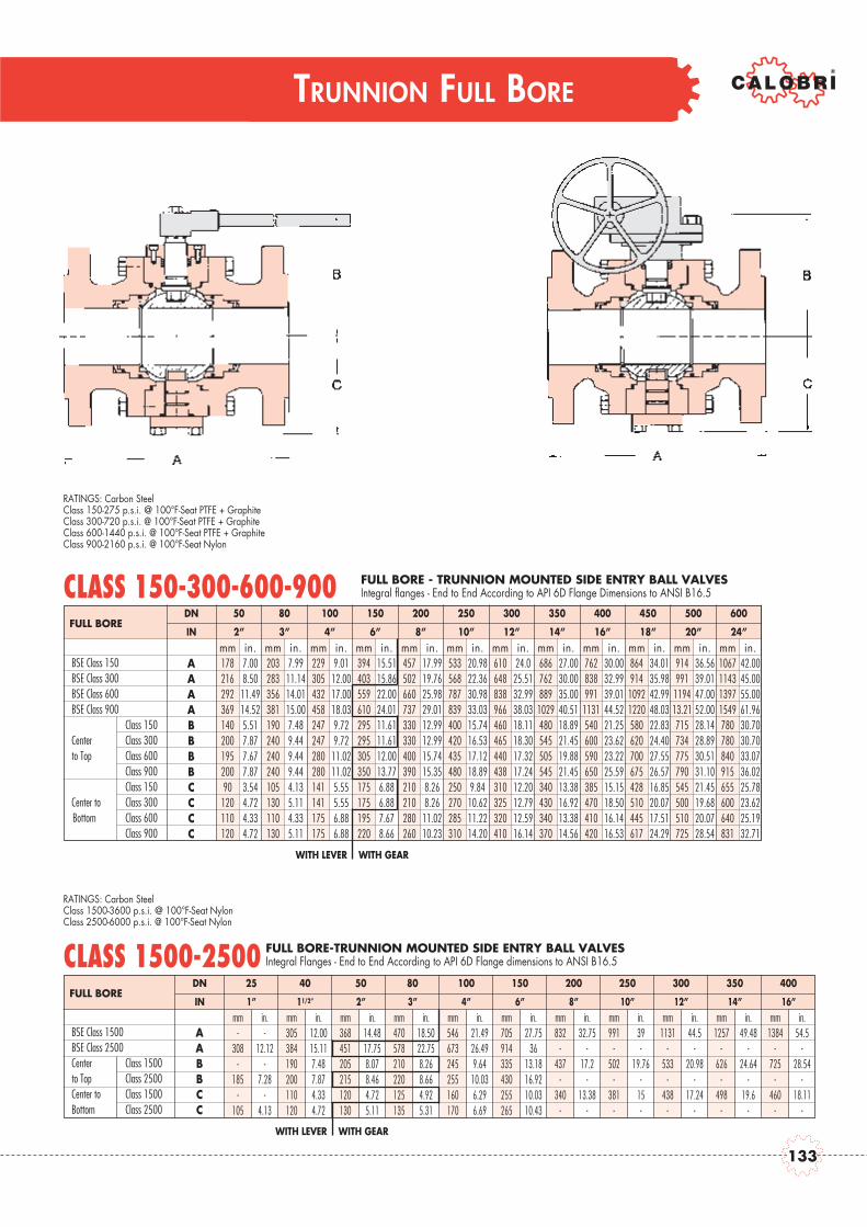
TRUNNION FULL BORE
BSE Class 1500BSE Class 2500Center Class 1500to Top Class 2500Center to Class 1500Bottom Class 2500
FULL BOREDN 50 80 100 150 200 250 300 350 400 450 500 600
IN 2” 3” 4” 6” 8” 10” 12” 14” 16” 18” 20” 24”
FULL BOREDN 25 40 50 80 100 150 200 250 300 350 400
IN 1” 11/2” 2” 3” 4” 6” 8” 10” 12” 14” 16”mm in. mm in. mm in. mm in. mm in. mm in. mm in. mm in. mm in. mm in. mm in.
- - 305 12.00 368 14.48 470 18.50 546 21.49 705 27.75 832 32.75 991 39 1131 44.5 1257 49.48 1384 54.5308 12.12 384 15.11 451 17.75 578 22.75 673 26.49 914 36 - - - - - - - - - -
- - 190 7.48 205 8.07 210 8.26 245 9.64 335 13.18 437 17.2 502 19.76 533 20.98 626 24.64 725 28.54185 7.28 200 7.87 215 8.46 220 8.66 255 10.03 430 16.92 - - - - - - - - - -
- - 110 4.33 120 4.72 125 4.92 160 6.29 255 10.03 340 13.38 381 15 438 17.24 498 19.6 460 18.11105 4.13 120 4.72 130 5.11 135 5.31 170 6.69 265 10.43 - - - - - - - - - -
mm203283356381190240240240105130110130
mm229305432458247247280280141141175175
mm394403559610295295305350175175195220
mm457502660737330330400390210210280260
mm533568787839400420435480250270285310
mm610648838966460465440438310325320410
mm686762889
1029480545505545340430340370
mm7628389911131540600590650385470410420
mm86491410921220580620700675428510445617
mm914991119413.21715734775790545500510725
mm1067114313971549780780840915655600640831
BSE Class 150BSE Class 300BSE Class 600BSE Class 900
Class 150Center Class 300to Top Class 600
Class 900Class 150
Center to Class 300Bottom Class 600
Class 900
mm17821629236914020019520090
120110120
in.7.008.5011.4914.525.517.877.677.873.544.724.334.72
CLASS 150-300-600-900 FULL BORE - TRUNNION MOUNTED SIDE ENTRY BALL VALVESIntegral flanges - End to End According to API 6D Flange Dimensions to ANSI B16.5
in.7.9911.1414.0115.007.489.449.449.444.135.114.335.11
in.9.0112.0017.0018.039.729.7211.0211.025.555.556.886.88
in.15.5115.8622.0024.0111.6111.6112.0013.776.886.887.678.66
in.17.9919.7625.9829.0112.9912.9915.7415.358.268.2611.0210.23
in.20.9822.3630.9833.0315.7416.5317.1218.899.8410.6211.2214.20
in.24.0
25.5132.9938.0318.1118.3017.3217.2412.2012.7912.5916.14
in.27.0030.0035.0040.5118.8921.4519.8821.4513.3816.9213.3814.56
in.30.0032.9939.0144.5221.2523.6223.2225.5915.1518.5016.1416.53
in.34.0135.9842.9948.0322.8324.4027.5526.5716.8520.0717.5124.29
in.36.5639.0147.0052.0028.1428.8930.5131.1021.4519.6820.0728.54
in.42.0045.0055.0061.9630.7030.7033.0736.0225.7823.6225.1932.71
AAAABBBBCCCC
RATINGS: Carbon Steel Class 1500-3600 p.s.i. @ 100°F-Seat NylonClass 2500-6000 p.s.i. @ 100°F-Seat Nylon
CLASS 1500-2500 FULL BORE-TRUNNION MOUNTED SIDE ENTRY BALL VALVESIntegral Flanges - End to End According to API 6D Flange dimensions to ANSI B16.5
AABBCC
RATINGS: Carbon Steel Class 150-275 p.s.i. @ 100°F-Seat PTFE + GraphiteClass 300-720 p.s.i. @ 100°F-Seat PTFE + GraphiteClass 600-1440 p.s.i. @ 100°F-Seat PTFE + GraphiteClass 900-2160 p.s.i. @ 100°F-Seat Nylon
WITH LEVER WITH GEAR
WITH LEVER WITH GEAR
133
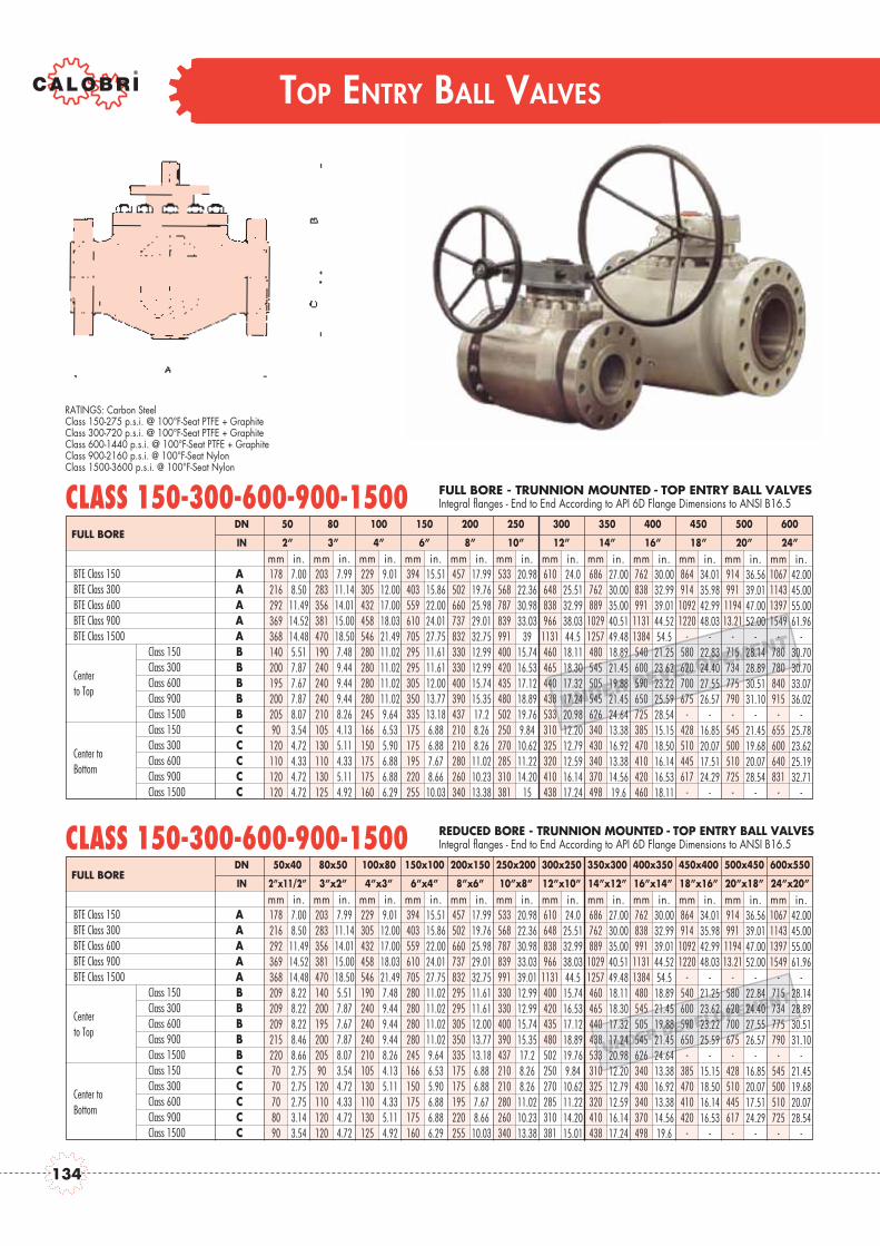
TOP ENTRY BALL VALVES
UNDER DEVELOPEMENT
UNDER DEVELOPEMENT
FULL BOREDN 50x40 80x50 100x80 150x100 200x150 250x200 300x250 350x300 400x350 450x400 500x450 600x550
IN 2”x11/2” 3”x2” 4”x3” 6”x4” 8”x6” 10”x8” 12”x10” 14”x12” 16”x14” 18”x16” 20”x18” 24”x20”mm20328335638147014020019520020590
120110120120
mm229305432458546190240240240210105130110130125
mm394403559610705280280280280245166150175175160
mm457502660737832295295305350335175175195220255
mm533568787839991330330400390437210210280260340
BTE Class 150 BTE Class 300 cat. F1-CT-600BTE Class 600BTE Class 900BTE Class 1500
Class 150Class 300
CenterClass 600
to Top Class 900Class 1500Class 150Class 300
Center toClass 600
BottomClass 900Class 1500
mm1782162923693682092092092152207070708090
in.7.008.50
11.4914.5214.488.228.228.228.468.662.752.752.753.143.54
CLASS 150-300-600-900-1500
in.7.99
11.1414.0115.0018.505.517.877.677.878.073.544.724.334.724.72
in.9.01
12.0017.0018.0321.497.489.449.449.448.264.135.114.335.114.92
in.15.5115.8622.0024.0127.7511.0211.0211.0211.029.646.535.906.886.886.29
in.17.9919.7625.9829.0132.7511.6111.6112.0013.7713.186.886.887.678.66
10.03
in.20.9822.3630.9833.0339.0112.9912.9915.7415.3517.28.268.26
11.0210.2313.38
in.24.0
25.5132.9938.0344.5
15.7416.5317.1218.8919.769.84
10.6211.2214.2015.01
in.27.0030.0035.0040.5149.4818.1118.3017.3217.2420.9812.2012.7912.5916.1417.24
in.30.0032.9939.0144.5254.5
18.8921.4519.8821.4524.6413.3816.9213.3814.5619.6
in.34.0135.9842.9948.03
-21.2523.6223.2225.59
-15.1518.5016.1416.53
-
in.36.5639.0147.0052.00
-22.8424.4027.5526.57
-16.8520.0717.5124.29
-
in.42.0045.0055.0061.96
-28.1428.8930.5131.10
-21.4519.6820.0728.54
-
AAAAABBBBBCCCCC
mm610648838966
1131400420435480502250270285310381
mm686762889
10291257460465440438533310325320410438
mm76283899111311384480545505545626340430340370498
mm864914
10921220
-540600590650
-385470410420
-
mm914991
119413.21
-580620700675
-428510445617
-
mm1067114313971549
-715734775790
-545500510725
-
REDUCED BORE - TRUNNION MOUNTED - TOP ENTRY BALL VALVESIntegral flanges - End to End According to API 6D Flange Dimensions to ANSI B16.5
FULL BOREDN 50 80 100 150 200 250 300 350 400 450 500 600
IN 2” 3” 4” 6” 8” 10” 12” 14” 16” 18” 20” 24”mm203283356381470190240240240210105130110130125
mm229305432458546280280280280245166150175175160
mm394403559610705295295305350335175175195220255
mm457502660737832330330400390437210210280260340
mm533568787839991400420435480502250270285310381
BTE Class 150 BTE Class 300 cat. F1-CT-600BTE Class 600BTE Class 900BTE Class 1500
Class 150Class 300
CenterClass 600
to Top Class 900Class 1500Class 150Class 300
Center toClass 600
BottomClass 900Class 1500
mm17821629236936814020019520020590120110120120
in.7.008.50
11.4914.5214.485.517.877.677.878.073.544.724.334.724.72
CLASS 150-300-600-900-1500
in.7.99
11.1414.0115.0018.507.489.449.449.448.264.135.114.335.114.92
in.9.01
12.0017.0018.0321.4911.0211.0211.0211.029.646.535.906.886.886.29
in.15.5115.8622.0024.0127.7511.6111.6112.0013.7713.186.886.887.678.6610.03
in.17.9919.7625.9829.0132.7512.9912.9915.7415.3517.28.268.26
11.0210.2313.38
in.20.9822.3630.9833.03
3915.7416.5317.1218.8919.769.84
10.6211.2214.20
15
in.24.0
25.5132.9938.0344.5
18.1118.3017.3217.2420.9812.2012.7912.5916.1417.24
in.27.0030.0035.0040.5149.4818.8921.4519.8821.4524.6413.3816.9213.3814.5619.6
in.30.0032.9939.0144.5254.5
21.2523.6223.2225.5928.5415.1518.5016.1416.5318.11
in.34.0135.9842.9948.03
-22.8324.4027.5526.57
-16.8520.0717.5124.29
-
in.36.5639.0147.0052.00
-28.1428.8930.5131.10
-21.4519.6820.0728.54
-
in.42.0045.0055.0061.96
-30.7030.7033.0736.02
-25.7823.6225.1932.71
-
AAAAABBBBBCCCCC
RATINGS: Carbon Steel Class 150-275 p.s.i. @ 100°F-Seat PTFE + GraphiteClass 300-720 p.s.i. @ 100°F-Seat PTFE + GraphiteClass 600-1440 p.s.i. @ 100°F-Seat PTFE + GraphiteClass 900-2160 p.s.i. @ 100°F-Seat NylonClass 1500-3600 p.s.i. @ 100°F-Seat Nylon
mm686762889
10291257480545505545626340430340370498
mm76283899111311384540600590650725385470410420460
mm864914
10921220
-580620700675
-428510445617
-
mm914991
119413.21
-715734775790
-545500510725
-
mm1067114313971549
-780780840915
-655600640831
-
FULL BORE - TRUNNION MOUNTED - TOP ENTRY BALL VALVESIntegral flanges - End to End According to API 6D Flange Dimensions to ANSI B16.5
mm610648838966
1131460465440438533310325320410438
134
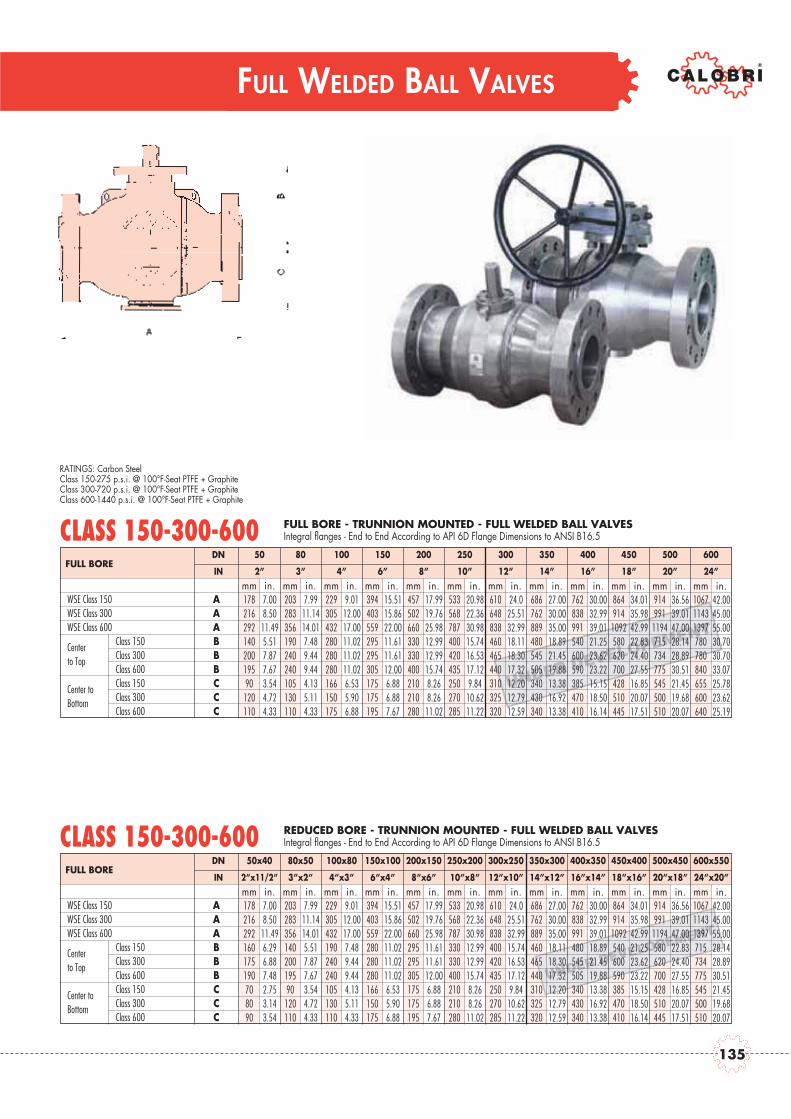
FULL WELDED BALL VALVES
UNDER DEVELOPEMENT
FULL BOREDN 50 80 100 150 200 250 300 350 400 450 500 600
IN 2” 3” 4” 6” 8” 10” 12” 14” 16” 18” 20” 24”mm203283356190240240105130110
mm229305432280280280166150175
mm394403559295295305175175195
mm457502660330330400210210280
mm533568787400420435250270285
WSE Class 150 WSE Class 300 cat. F1-CT-600WSE Class 600
Class 150CenterClass 300to TopClass 600Class 150Center toClass 300BottomClass 600
mm17821629214020019590
120110
in.7.008.50
11.495.517.877.673.544.724.33
CLASS 150-300-600 FULL BORE - TRUNNION MOUNTED - FULL WELDED BALL VALVESIntegral flanges - End to End According to API 6D Flange Dimensions to ANSI B16.5
in.7.99
11.1414.017.489.449.444.135.114.33
in.9.01
12.0017.0011.0211.0211.026.535.906.88
in.15.5115.8622.0011.6111.6112.006.886.887.67
in.17.9919.7625.9812.9912.9915.748.268.26
11.02
in.20.9822.3630.9815.7416.5317.129.84
10.6211.22
in.24.025.5132.9918.1118.3017.3212.2012.7912.59
in.27.0030.0035.0018.8921.4519.8813.3816.9213.38
in.30.0032.9939.0121.2523.6223.2215.1518.5016.14
in.34.0135.9842.9922.8324.4027.5516.8520.0717.51
in.36.5639.0147.0028.1428.8930.5121.4519.6820.07
in.42.0045.0055.0030.7030.7033.0725.7823.6225.19
AAABBBCCC
RATINGS: Carbon Steel Class 150-275 p.s.i. @ 100°F-Seat PTFE + GraphiteClass 300-720 p.s.i. @ 100°F-Seat PTFE + GraphiteClass 600-1440 p.s.i. @ 100°F-Seat PTFE + Graphite
mm610648838460465440310325320
mm686762889480545505340430340
mm762838991540600590385470410
mm864914
1092580620700428510445
mm9149911194715734775545500510
mm106711431397780780840655600640
UNDER DEVELOPEMENT
FULL BOREDN 50x40 80x50 100x80 150x100 200x150 250x200 300x250 350x300 400x350 450x400 500x450 600x550
IN 2”x11/2” 3”x2” 4”x3” 6”x4” 8”x6” 10”x8” 12”x10” 14”x12” 16”x14” 18”x16” 20”x18” 24”x20”mm20328335614020019590120110
mm229305432190240240105130110
mm394403559280280280166150175
mm457502660295295305175175195
mm533568787330330400210210280
WSE Class 150 WSE Class 300 cat. F1-CT-600WSE Class 600
Class 150CenterClass 300to TopClass 600Class 150Center toClass 300BottomClass 600
mm178216292160175190708090
in.7.008.50
11.496.296.887.482.753.143.54
CLASS 150-300-600 REDUCED BORE - TRUNNION MOUNTED - FULL WELDED BALL VALVESIntegral flanges - End to End According to API 6D Flange Dimensions to ANSI B16.5
in.7.99
11.1414.015.517.877.673.544.724.33
in.9.01
12.0017.007.489.449.444.135.114.33
in.15.5115.8622.0011.0211.0211.026.535.906.88
in.17.9919.7625.9811.6111.6112.006.886.887.67
in.20.9822.3630.9812.9912.9915.748.268.2611.02
in.24.025.5132.9915.7416.5317.129.8410.6211.22
in.27.0030.0035.0018.1118.3017.3212.2012.7912.59
in.30.0032.9939.0118.8921.4519.8813.3816.9213.38
in.34.0135.9842.9921.2523.6223.2215.1518.5016.14
in.36.5639.0147.0022.8324.4027.5516.8520.0717.51
in.42.0045.0055.0028.1428.8930.5121.4519.6820.07
AAABBBCCC
mm610648838400420435250270285
mm686762889460465440310325320
mm762838991480545505340430340
mm864914
1092540600590385470410
mm9149911194580620700428510445
mm106711431397715734775545500510
135

MATERIAL
CALOBRI valves are manufactured in a wide range of materials, supplied by the best available steel mills, forged bywell experienced forgeries with the most up to date equipment. All the materials can be certified in the chemical composition and the mechanical characteristic.
* Selection of seat insert is limited by the actual service temperaturemetal to metal seatings are also available
MATERIAL SPECIFICATIONS FOR TRUNNION MOUNTED VALVESService Non sour Sour
Part Name minus 45°C up to plus 180°C minus 29°C up to plus 180°C minus 45°C up to plus 180°C minus 29°C up to plus 180°CBody/Cover LF2 A105 (N) LF2 A105 (N)Ball LF2 A105 (N) LF2 enp 0.075 A105 (N) enp 0.075Seat LF2 A105 (N) LF2 enp 0.075 A105 (N) enp 0.075Stem LF2 A105 (N) LF2 enp 0.075 A105 (N) enp 0.075Trunnion LF2 A105 (N) LF2 enp 0.075 A105 (N) enp 0.075Seat Insert* Rtfe or nylon or devlon Rtfe or nylon or devlon Rtfe or nylon or devlon Rtfe or nylon or devlonSeal Viton Viton Viton VitonSprings Inconel X750 Inconel X750 Inconel X750 Inconel X750Bolting L7/4 B7/2H L7M/4M B7M/2MAdaptor Plate A105 A105 A105 A105Screws Gr 8.8 Zinc plated Gr 8.8 Zinc plated Gr 8.8 Zinc plated Gr 8.8 Zinc platedBill of Materials BM1 BM2 BM3 BM4
(LF2/LF2) (A105N/A105N) (LF2/LF2 enp 0.075) (A105N/A105N enp 0.075)
* Selection of seat insert is limited by the actual service temperaturemetal to metal seatings are also available
MATERIAL SPECIFICATIONS FOR TRUNNION MOUNTED VALVESSERVICE High Temperature
Part Name minus 29°C up to plus 260°C minus 29°C up to plus 180°C minus 180°C up to plus 210°CBody/Cover A105 (N) Duplex F51 F316Ball A105 enp 0.075 Duplex F51 F316 (or Tungsten)Seat A105 enp 0.075 Duplex F51 F316 (or Tungsten)Stem 17-4PH Duplex F51 17-4PHTrunnion A105 enp. 0.075 Duplex F51 F316Seat Insert* Peek Rtfe or nylon or devlon or peek Rtfe or nylon or Kel-FSeal Viton or ptfe + inconel Viton VitonSprings Inconel X750 Inconel X750 Inconel X750Bolting B7/2H B8M/8M B8/8Adaptor Plate A105 316 st/st 316Screws Gr 8.8 zinc plated A4-70 A4-70Bill of Materials BM5 BM6 BM7
(A105/A105 enp 0.075 - 17-4PH) (F51/F51) (F316/316 enp 0.025 - 17-4PH)
Marine Offshore Corrosive
136

MATERIAL
CALOBRI valves are manufactured in a wide range of materials, supplied by the best available steel mills, forged bywell experienced forgeries with the most up to date equipment. All the materials can be certified in the chemical composition and the mechanical characteristic.
* Selection of seat insert is limited by the actual service temperaturemetal to metal seatings are also available
MATERIAL SPECIFICATIONS FOR TRUNNION MOUNTED VALVESService Non sour Sour
Part Name minus 45°C up to plus 180°C minus 29°C up to plus 180°C minus 45°C up to plus 180°C minus 29°C up to plus 180°CBody/Cover LF2 A105 (N) LF2 A105 (N)Ball LF2 A105 (N) LF2 enp 0.075 A105 (N) enp 0.075Seat LF2 A105 (N) LF2 enp 0.075 A105 (N) enp 0.075Stem LF2 A105 (N) LF2 enp 0.075 A105 (N) enp 0.075Trunnion LF2 A105 (N) LF2 enp 0.075 A105 (N) enp 0.075Seat Insert* Rtfe or nylon or devlon Rtfe or nylon or devlon Rtfe or nylon or devlon Rtfe or nylon or devlonSeal Viton Viton Viton VitonSprings Inconel X750 Inconel X750 Inconel X750 Inconel X750Bolting L7/4 B7/2H L7M/4M B7M/2MAdaptor Plate A105 A105 A105 A105Screws Gr 8.8 Zinc plated Gr 8.8 Zinc plated Gr 8.8 Zinc plated Gr 8.8 Zinc platedBill of Materials BM1 BM2 BM3 BM4
(LF2/LF2) (A105N/A105N) (LF2/LF2 enp 0.075) (A105N/A105N enp 0.075)
* Selection of seat insert is limited by the actual service temperaturemetal to metal seatings are also available
MATERIAL SPECIFICATIONS FOR TRUNNION MOUNTED VALVESSERVICE High Temperature
Part Name minus 29°C up to plus 260°C minus 29°C up to plus 180°C minus 180°C up to plus 210°CBody/Cover A105 (N) Duplex F51 F316Ball A105 enp 0.075 Duplex F51 F316 (or Tungsten)Seat A105 enp 0.075 Duplex F51 F316 (or Tungsten)Stem 17-4PH Duplex F51 17-4PHTrunnion A105 enp. 0.075 Duplex F51 F316Seat Insert* Peek Rtfe or nylon or devlon or peek Rtfe or nylon or Kel-FSeal Viton or ptfe + inconel Viton VitonSprings Inconel X750 Inconel X750 Inconel X750Bolting B7/2H B8M/8M B8/8Adaptor Plate A105 316 st/st 316Screws Gr 8.8 zinc plated A4-70 A4-70Bill of Materials BM5 BM6 BM7
(A105/A105 enp 0.075 - 17-4PH) (F51/F51) (F316/316 enp 0.025 - 17-4PH)
Marine Offshore Corrosive
137
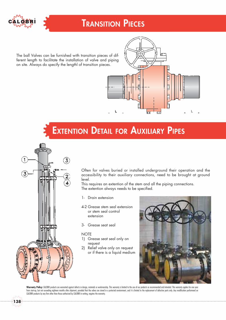
Often for valves buried or installed underground their operation and theaccessibility to their auxiliary connections, need to be brought at groundlevel.This requires an extention of the stem and all the piping connections. The extention always needs to be specified.
1- Drain extension
4-2 Grease stem seal extension or stem seal control extension
3- Grease seat seal
NOTE1) Grease seat seal only on
request2) Relief valve only on request
or if there is a liquid medium
The ball Valves can be furnished with transition pieces of dif-ferent length to facilitate the installation of valve and pipingon site. Always do specify the lengthl of transition pieces.
Warranty Policy: CALOBRI products are warranted against defects in design, materials or workmanship. This warranty is limited to the use of our products as recommended and intended. This warranty applies for one yearfrom start-up, but not exceeding eighteen months after shipment, provided that the valves are stored in a protected environment, and it is limited to the replacement of defective parts only. Any modification performend onCALOBRI products by any firm other than those authorized by CALOBRI in writing, negates the warranty.
TRANSITION PIECES
EXTENTION DETAIL FOR AUXILIARY PIPES
138

NOTE
135

Via Newton, 420019 Settimo Milanese - Milan, ITALYTel. +39.02.3282951Fax +39.02.3281558
www.calobri.com
LOCAL DISTRIBUTOR:
CA
L_02
12.
10
ENG
INEE
RED
BY
CA
LOBR
I TEC
HN
ICA
L O
FFIC
E