
VALVE - Polisois audio and Simplex Redux .pdf · Ari Polisois ©2001, 2002 The Simplex Single-ended...
30
VALVE Page 1 The Idea After having built several audio amplifiers (single-ended and push-pull) and compared, first their theoretical quali- ties, then the practical side (complexity, matching of the valves and need of adjustments) and, last but not least, the sound, I decided in favor of the single-ended. I was much inspired by the wonderful article written by Scott Frankland on the Dec. 96 and Jan-Feb. 97 issues of Stereophile. There was another reason for me to choose this layout: by by by by Ari Polisois Ari Polisois Ari Polisois Ari Polisois ©2001, 2002 The Simplex Single-ended Audio Amplifier VALVE VALVE VALVE VALVE the magazine of astounding sound the magazine of astounding sound the magazine of astounding sound the magazine of astounding sound The Simplex The Simplex The Simplex The Simplex
Transcript of VALVE - Polisois audio and Simplex Redux .pdf · Ari Polisois ©2001, 2002 The Simplex Single-ended...
VALVE Page 1
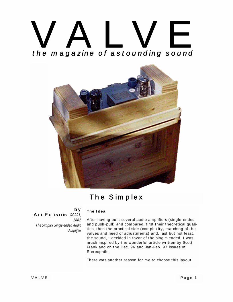
The Idea
After having built several audio amplifiers (single-endedand push-pull) and compared, first their theoretical quali-ties, then the practical side (complexity, matching of thevalves and need of adjustments) and, last but not least,the sound, I decided in favor of the single-ended. I wasmuch inspired by the wonderful article written by ScottFrankland on the Dec. 96 and Jan-Feb. 97 issues ofStereophile.
There was another reason for me to choose this layout:
bybybybyAri Polisois Ari Polisois Ari Polisois Ari Polisois ©2001,
2002The Simplex Single-ended Audio
Amplifier
VALVEVALVEVALVEVALVEthe magazine of astounding soundthe magazine of astounding soundthe magazine of astounding soundthe magazine of astounding sound
The SimplexThe SimplexThe SimplexThe Simplex
VALVE Page 2
single ended amplifiers are less expensive to build, interms of cost of components and time spent to assemblethem. My plan was to design an amplifier as simple aspossible, still keeping the quality high. The latest one Icompleted a week ago has an incredibly pure sound, byfar the best, compared to the others I had so far built,that were considered, until then, by all people who lis-tened to them, of having an impressive good sound.
My wish is that someone else decides to build its twinand share his impressions with me. Surely, with differentspeaker systems and listening rooms, etc...the compari-son will be questionable, but, nevertheless, some charac-ter should show up.
I gave the amp the name Simplex, as it is to me: Simpleand excellent. At first sight it is not so simple, due to thefact that it contains some novel solutions and, undoubt-edly, everything new implies effort to be fully under-stood. But once you have accepted them, I bet you willuse them as an alternative to the traditional and too of-ten repeated circuits, most of which polluted by compro-mises that reduce the sound quality. I am aware thatwhat I am saying seems quite arrogant. Take it as an in-vitation to prove the opposite.
I decided to use the bulky but generous 6C33C, driven bythe evergreen 6SN7, for the following reasons:
• the 6C33C has a lot of potential as it can deliver asubstantial amount of power
• it works at quite a low plate voltage
• it has a wide filament/heater surface
• its price is affordable.
On the other hand, it requires a high driving swing, inthe range of 85-100V peak. It took me some time to ob-tain this swing from a 6SN7, but this beautiful valve suc-ceeded, with an acceptable distortion figure, an unbeliev-ably extended frequency range (from few Hertz to over150 kHz) and, consequently, with a respectable linearity.
The simulations suggested a biasing voltage of -90 forthe 6C33C, a B+ of 270V and an idle plate current of 250mA. The plate load was set at 800 ohms, with a ratio of10:1 on an 8 ohm load.
Raw Power requirements
At first I will refrain to spend much time and space on
VA
LV
EP
age 3
VALVE Page 4
VALVE Page 5
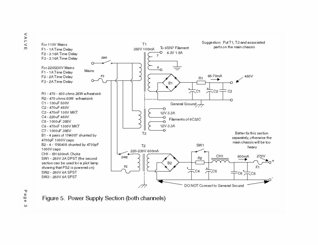
the power supplies, considering that this subject is recur-rent in almost every description of an audio amplifier. Asper Fig. #5, you need TWO, different ones. Why will be ex-plained later in the text. The first, intended for the driversections, must be able to deliver 425V at about 100 mA(actually each driver requires approx. 32 mA) and the sec-ond, for the 6C33Cs, 270V at 500-600 mA idle (in total,that is, for both power tubes). I decided to use one trans-former (T1) just for the driver section, another (T3) for the6C33C filaments, requiring (each valve) 12.6 V at 3.3 A.
A third, separate transformer of 150-200VA was meant forthe B+ supply of the 6C33Cs. A 110-220V to 220V mainsinsulating transformer would do, because you need to have220V across the rectifying bridge (I used four 1N5408diodes, rated 1000V 3 Amps, followed by a 220 µF 350Vgood quality electrolytic). From my experience, it is betterto build, at first, the driver section and its power supply onone chassis, on which you fitted, at the same time, the6C33C's sockets. No output transformers, for the time be-ing, to have the chassis lighter for tests and measure-ments.
The dimensions recommended for this chassis (not includ-ing the Power supply for the 6C33Cs - see next paragraph)are no less than 12" x 16" (30 x 40 cm.). This accommo-dates both channels, with their OPTs. Also, an advisable so-lution is to have the power supply for the Power Tubesphysically separated, in a metal box and connected to themain chassis with a three-wire cord (+270V, Null and con-trol wire, if necessary).
The Driver Section
One of the classic circuits I admire is the direct couplingused by Williamson in his famous amplifier: the first tri-ode's plate connected directly, that is, without any blockingcondenser, to the grid of the second triode. The potential ofthe cathode must be higher, to ensure the necessary bias(between - 7 and - 9 V, depending on the actual character-istics of the tube used). In the Williamson, the second tri-ode is also a phase inverter. We do not need it here, be-cause of the single-ended topology.
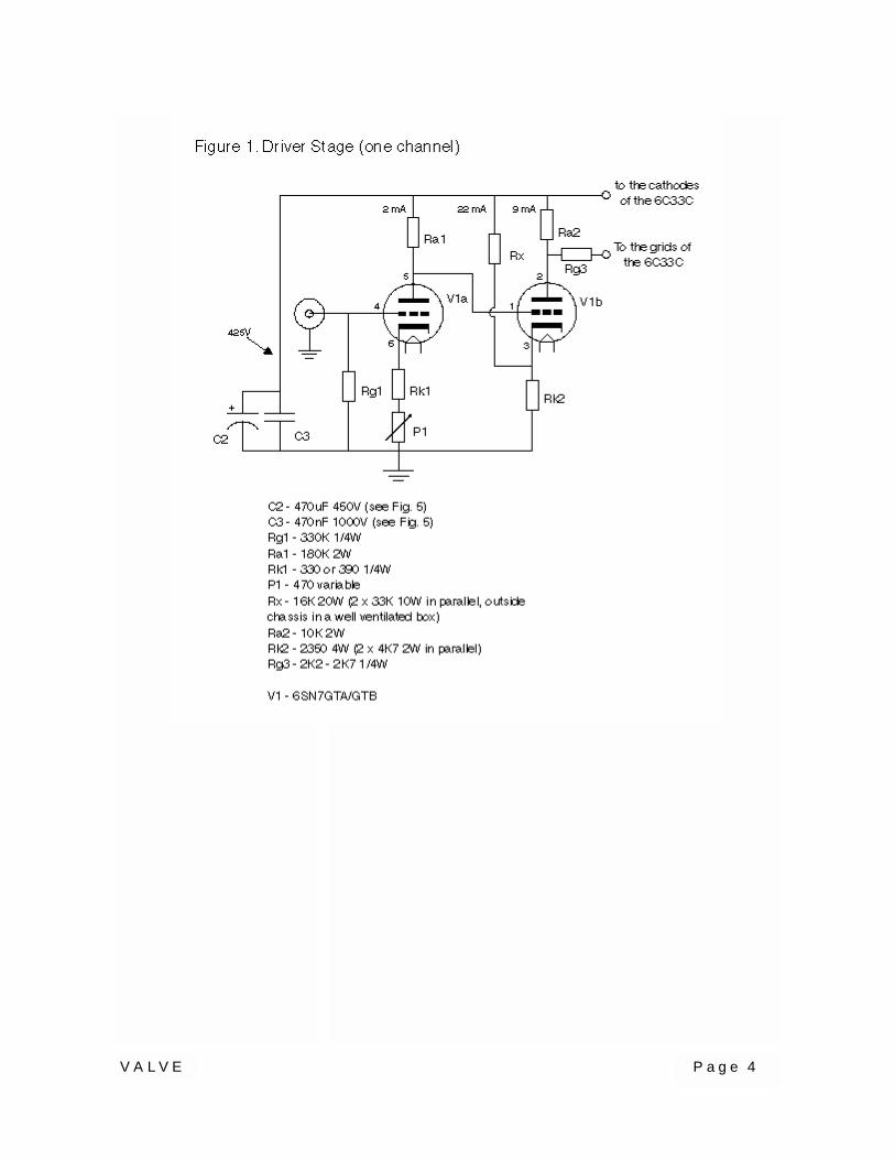
Let us have a look at Fig. #1. V1a is the first section of the6SN7 (pins 4, 5, 6 preferably). Its plate (pin #5) is con-nected directly to pin #1 (grid of the second triode). Youwill notice the usual grid resistor Rg1, connecting the input"i" to ground, as well as Rk1 and P1, both acting to providethe cathode bias to V1a. The purpose of P1 is to vary thebias of V1a as required, within certain limits. We will see
VALVE Page 6
later why, but we can state immediately that the adjust-ment of P1 also varies the potential level of the anode ofV1a (which is directly connected to the grid of V1b), withrespect to the cathode (pin #3). The consequence is thatalso the bias of V1b changes, modifying the plate cur-rent. The plate load of V1b, the resistor Ra2, catches adifferent voltage, depending on the setting of P1. Inother words, P1 controls the voltage drop across Ra2.
What is the purpose of Rx? This hi-wattage resistor sup-plies an extra current to Rk2, adding to V1b's idle anodecurrent. This layout has two main effects:
a) the local negative feed-back, taking place because ofthe absence of a by-pass condenser across Rk2, improvesthe performance of V1b (in fact I measured a drop of75% in THD) at the expense, of course, of a reduction ofgain by almost the same proportion;
b) The extra 22 mA current supplied by Rx, reduces theneed of a higher value resistor Rk2, still providing for thevoltage level to counter-act V1a's plate voltage(remember that the bias of V1b is the difference betweenthe Voltage at pin 5 and pin 3). The advantage is thatthe ratio Ra2/Rk2 is improved and because the gain ofV1b depends on this ratio, the amplification jumps from1 to 4, approximately.
Just a word on Rg3. It has become a habit to fit a small(few kilo-ohms) resistor, before the output tube's grids,to avoid any parasitic oscillation.
The Output Stage
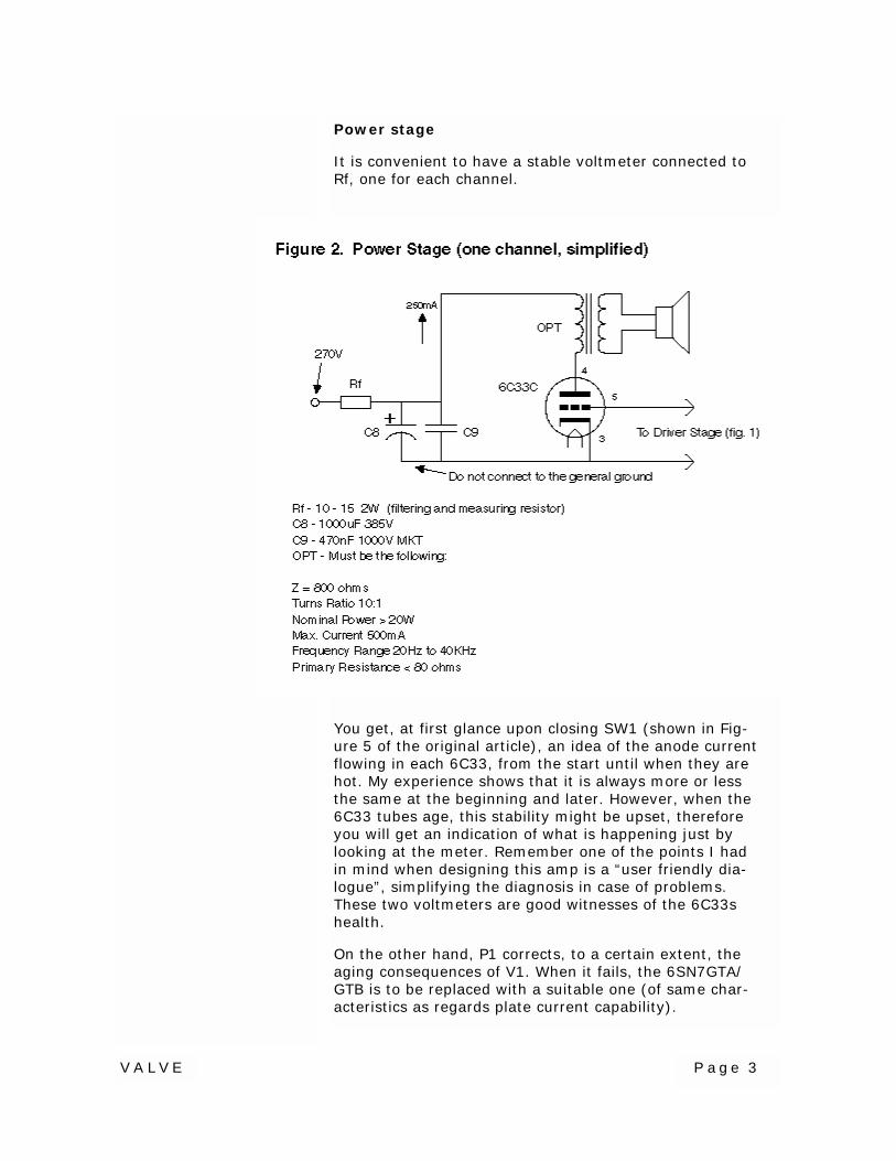
Now, how is the driver connected to the power tube?Very simple: plate to grids, because the 6C33 has 2 grids(pin #5), without any blocking condenser (just Rg3, asexplained above) and B+ terminal to cathodes (Pin #3).This is made possible by the fact that there are TWOdedicated power supplies, one for the driver and one forthe output tubes and they do not have their negative ter-minals connected together. In fact, the Power stage's B-is, instead, connected to the Driver stage's B+. Fig. #2illustrates the power section. The polarity of the voltageacross Ra2 suits the bias requirement (minus to grid andplus to cathode).
Now, please do not tell me that this is a complication.What difference does it make to have two smaller trans-formers instead of a single but bulky and heavy one witha lot of outgoing wires? It is true that you need two dif-ferent filtering sets, and this is quite expensive, but, in

VALVE Page 7

VA
LV
EP
age 8
VALVE Page 9
any case, you always have to separate the output stagepower positive voltage source and the driver source withsome kind of resistor/choke plus condenser combina-tions.
You can now examine the general architecture of the am-plifier in Fig. #3. Note how few are the components ofthe amplifying/power stages. The root "simple", of theword SIMPLEX is thus explained.
With regard to the power supplies, unfortunately there isnothing I can do to reduce their size nor the number ofcomponents. The more they are generously furnished,the better the amplifier's performance, within certain lim-its, of course. Just one additional word on the subject: T3(Fig. #3) is better located on the main chassis, not toofar from the 6C33C sockets, because of the high currentflowing in the wires. Fig. #4 shows the area reserved forthe driver section as well as for T3 (approx. 8 x 16inches). The output transformers find their place on theback corners, thus requiring an extension of the abovebasic area to 12 x 16" ; however, in the topology I havechosen, the 6C33Cs are in the front row and the OPTs onthe sides. If the amplifier is at reach of inexperiencedpersons, make a provision to surround at least the outputtubes with a protection against burns.
Testing the Driver Section
Going back to Fig. 1, you will notice the expected cur-rents in the three branches (V1a anode, V1b anode andthrough Rx), but this is just orientative. Assuming the PSvoltage is close to 425 Volts (if not, you can replace R1 -Fig. 5, by a suitable resistor), you should measure about65V at pin 5 (same as pin 1) of the 6SN7, with respect toground.
The opponent voltage present at pin 3 should be higher,but by less than 10 Volts (say 73V to 74V with respect toground. Any difference is due to the tolerances of thecomponents, including tubes. What matters is the anodecurrent of V1b. By adjusting P1 you should be able tohave a drop of 90V across Ra2 (Fig. 1). If the drop islower even at P1's limit, set P1 in the middle position andfind a suitable shunting resistor (normally 33K 2W shoulddo) to reduce Rk2's value. The plate current of V1bshould increase and so the drop across Ra2. When both6SN7 are checked, your driver's channels are ready.
Testing the Power Section
The DC power is supplied to the output tubes through a

VA
LV
EP
age 1
0
VALVE Page 11
low ohm resistor (10 to 15 Ohms 2W). I have fitted two13 ohm 3W resistors (available), one in each channelpath. This addition serves three purposes:
• it allows measuring the anode currents of eachpower tube (these should be 250 mA each but,actually can be substantially different, even withthe same bias level)
• it adds another filtering section to the commonone included in the 270V power supply box (asmentioned, this power supply is kept far from themain chassis and OPTs)
• It reduces the interference of one channel with re-spect to the other.
Now here comes a good question, with regard to A. Whatif, having adjusted the bias of the 6C33C at -90V, we finda higher or lower plate current? Well, if it is lower, wecan try first another 6C33C, to replace the "weak" one or,we can reduce the bias, say to -85V, until we get a platecurrent of about 250 mA. But if it is higher, we better notexceed 270-280 mA (playing with the bias level) or wemight damage the OPT (not the 6C33C, because it with-stands higher currents). In any case, we must watch notto exceed the rated admissible power dissipation, of60W, by more than 10%. Usually, with a regular tube,this case remains theoretical.
Lowering or increasing the bias level, I found, does notchange noticeably the overall performance of the ampli-fier. I tried with a bias of -85 V up to -100 V. The anodecurrent consumption varied a lot and probably, with thelower bias tests, the life of the 6C33C was somewhatshortened, but I cannot tell, at present, by how much.
The presence of high capacity filtering condensers hassuggested to insert R2 after the reservoir capacitor C4.This relatively high value (and wattage) resistor allows aslower charge of C5 and C7. Within a minute or so, SW1can be manually operated to short-circuit R2 and allowthe full amount of current to flow. This could also bedone with a relay, operated from the main chassis, usingthe third wire connecting the latter to the PS Box.
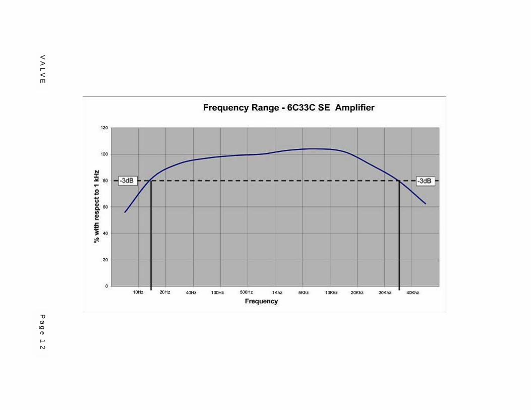
The Output Transformers
Fig. 2 gives a general indication of their characteristics.The OPTs I used are custom made and work fine, as canbe seen in the graph of frequency range and outputpower vs. THD. No other measurements have been made
VA
LV
EP
age 1
2

VA
LV
EP
age 1
3
VALVE Page 14
so far. If you can find a suitable transformer from a com-mercial source, make sure its primary can withstand atleast 400 mA. The ratio 10:1 allows a good power trans-fer. 7:1 can give more power but also more distortion. Ihope to be able to give more details on this subject in acoming article.
WARNING: the amplifier is super up to the OPT connec-tion. If you use a low grade output transformer, youloose a lot of brilliancy.
Questions
This chapter, I presume, should have been located at thebeginning and not at the end of the text. I refer to themain question many of you have in mind: "Why not use aregular blocking condenser, instead of a direct couplingbetween the driver and the output tube, requiring twopower supplies?"
Let me ask you: Are you aware of the damages to thesound, made by this cap? And also: Only if you listen tothe SimplEX you will be fully convinced, because of itsExcellent sound. If you don't believe what I say, youhave two main choices: forget this amplifier or build itand check.
Should you have other questions, I suggest to contactme by e-mail and I'll do my best to answer.
Ari Polisoisari.polisois at wanadoo.fr

VALVE Page 15
VALVEthe magazine ofthe magazine ofthe magazine ofthe magazine of
astounding soundastounding soundastounding soundastounding sound
Chief Editor and PublisherDan “Dr. Bottlehead” Schmalle
Managing EditorBrad “What in Sam Hill?” Brooks
Chief Administrator“Queen Eileen” Schmalle
Resident Smart Guy and Technical EditorPaul “Braniac” JoppaCopy and Art Editor
Jeanine “Titian” Edwards
VALVEVALVEVALVEVALVEEditorial and Advertising Inquiry
P.O. Box 68093Nashville, TN 37206
by Email: [email protected] Phone: 615-491-1903 CST
VALVE in no way assumes responsibility for anyone harming themselvesthrough exposure to the contents of this magazine. We believe electrons flow
from minus to plus, and that they can kill you along the way if you’re not care-ful. Vacuum tube audio equipment operates at potentially lethal voltages. Al-
ways treat it with respect.Many ideas published in this magazine are untried, and involve the use of po-
tentially dangerous parts and tools. In attempting any idea or project publishedherein, you assume total responsibility for your actions and any harm caused to
yourself or others.
This publication is produced as a service to the audio community and is wholly ownedand published by Bottlehead Corp. The intent of this publication is to offer ideas to in-spire and educate audiophiles in an effort to increase their understanding of the audioequipment that they use and cherish. Blatant copying of the circuits published in thismagazine for use in commercial products shows a complete lack of original thought.
Don’t just copy and distribute stuff without the author’s and publisher’s consent, OK?

VALVE Page 1
Resistors Explained
Starting from figure 1, the function of Rk1 and P1has been already explained. Ultimately, they gov-ern the plate current of the output valve 6C33C-B(see The Driver Section page from my article, TheSimplex).
A recommended upgrade is to bypass the 470ohm pot with a 1K 1/4W fixed resistor, moreover,use a good quality pot, for instance a Cermet,which has the reputation to last much longer, andto not produce scratchy noises. The natural ten-dency is to adjust this pot too often. Just wait un-til the 6C33s are warm enough and their anodecurrent settle at their normal operation level.
The value of Rk1 might need to be changed to ahigher value, say 470 ohms, should the voltagemeasured across Ra2 be lower than the one re-quired (between 85 and 95V when P1 is half way).
Paul Joppa defined the pair of resistors Rx andRk2 a voltage divider. This is actually a better def-inition than mine. I had considered Rx an auxiliarysource of current for Rk2, to raise its potentialwith respect to ground. A voltage divider gives theidea of a more stable voltage setting and, in fact,in the DCMB driver circuit described, the varia-tions of the anode current of V1b being a smallfraction of the current supplied through Rx, the V-level set by Rx-Rk2 does not change significantly.
bybybybyAri Polisois Ari Polisois Ari Polisois Ari Polisois ©2002
Focus on the novel performance ofthe Simplex 18W SE Amp, pub-
lished last issue, and making someimprovements
VALVEVALVEVALVEVALVEthe magazine of astounding soundthe magazine of astounding soundthe magazine of astounding soundthe magazine of astounding sound
SIMPLEX ReduxSIMPLEX ReduxSIMPLEX ReduxSIMPLEX Redux

VALVE Page 2
In addition to the increased gain (due to the improvedratio Ra2/Rk2), the amount of negative feed backcaused by the V1b’s plate current is reduced to a moreacceptable value.
Rg1 left and right channel can be replaced by a twinvolume control, such as an ALPS or similar, audio-taper20K or 50K. I found this necessary when connectingthe amp directly to a CD source, because some CDs arerecorded at loud levels. With this direct connection,you gain much in quality, unless you have a perfectpreamp.
VALVE Page 3
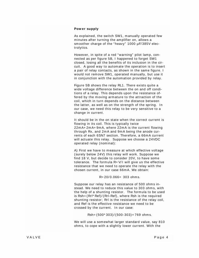
Power stage
It is convenient to have a stable voltmeter connected toRf, one for each channel.
You get, at first glance upon closing SW1 (shown in Fig-ure 5 of the original article), an idea of the anode currentflowing in each 6C33, from the start until when they arehot. My experience shows that it is always more or lessthe same at the beginning and later. However, when the6C33 tubes age, this stability might be upset, thereforeyou will get an indication of what is happening just bylooking at the meter. Remember one of the points I hadin mind when designing this amp is a “user friendly dia-logue”, simplifying the diagnosis in case of problems.These two voltmeters are good witnesses of the 6C33shealth.
On the other hand, P1 corrects, to a certain extent, theaging consequences of V1. When it fails, the 6SN7GTA/GTB is to be replaced with a suitable one (of same char-acteristics as regards plate current capability).
VALVE Page 4
Power supply
As explained, the switch SW1, manually operated fewminutes after turning the amplifier on, allows asmoother charge of the “heavy” 1000 µF/385V elec-trolytics.
However, in spite of a red “warning” pilot lamp, con-nected as per figure 5B, I happened to forget SW1closed, losing all the benefits of its inclusion in the cir-cuit. A good way to automate the operation is to inserta pair of relay contacts, as shown in the same figure. Iwould not remove SW1, operated manually, but use itin conjunction with the automation provided by relay.
Figure 5B shows the relay RL1. There exists quite awide voltage difference between the on and off condi-tions of a relay. This depends upon the resistance of-fered by the moving armature to the attraction of thecoil, which in turn depends on the distance betweenthe latter, as well as on the strength of the spring. Inour case, we need this relay to be very sensitive to achange in current.
It should be in the on state when the correct current isflowing in its coil. This is typically twice22mA+2mA+9mA, where 22mA is the current flowingthrough Rx, and 2mA and 9mA being the anode cur-rents of each 6SN7 section. Therefore, a 66mA currentwill actuate this relay. Suppose we choose a 24VDCoperated relay (nominal):
A) First we have to measure at which effective voltage(surely below 24V) this relay will work. Suppose wefind 18 V, but decide to consider 20V, to have sometolerance. The formula R=V/I will give us the effectiveresistance that we need to operate the relay with thechosen current, in our case 66mA. We obtain:
R=20/0.066= 303 ohms.
Suppose our relay has an resistance of 500 ohms in-stead. We need to reduce this value to 303 ohms, withthe help of a shunting resistor. The formula to be usedis Rsh=(Rrl*Ref)/(Rrl-Ref), where Rsh is the requiredshunting resistor; Rrl is the resistance of the relay coil,and Ref is the effective resistance we need to becrossed by the current. In our case:
Rsh=(500*303)/(500-303)=769 ohms.
We will use a somewhat larger standard value, say 810ohms, to cope with a slightly lower current. With the

VA
LV
EP
age 5
VALVE Page 6
same formula above, we will find the new effective re-sistance crossed by the addition of the above resistorin parallel:
Ref= (Rrl*Rsh)/(Rrl+Rsh)=(500*810)/(500+810)=309ohms.
The 20V level required to actuate the relay will then bereached with a lower current. This is given by the for-mula I=V/R, which equates to 20/309=0.0647, or0.065mA. If we need to increase the tolerance, we canfit a shunting resistor of approximately 1K. In suchcase, 60mA will suffice to actuate the relay.
NOTE: The adjustment of the relay sensitivity needs tobe performed without any connection to the amplifier.
B) Now comes the more delicate step: to make surethat the relay will go OFF, with the smallest (but rea-sonable) drop of current level. We can size this drop topretty close the current drawn by just one of the drivertubes (9+2mA), for instance 8mA , so that, in case thetube failed, for any reason, the relay contacts wouldopen, making the output tubes power supply quies-cent.
We could use an IC, or just a transistor operated sys-tem, but here is what I consider the simplest.
VALVE Page 7
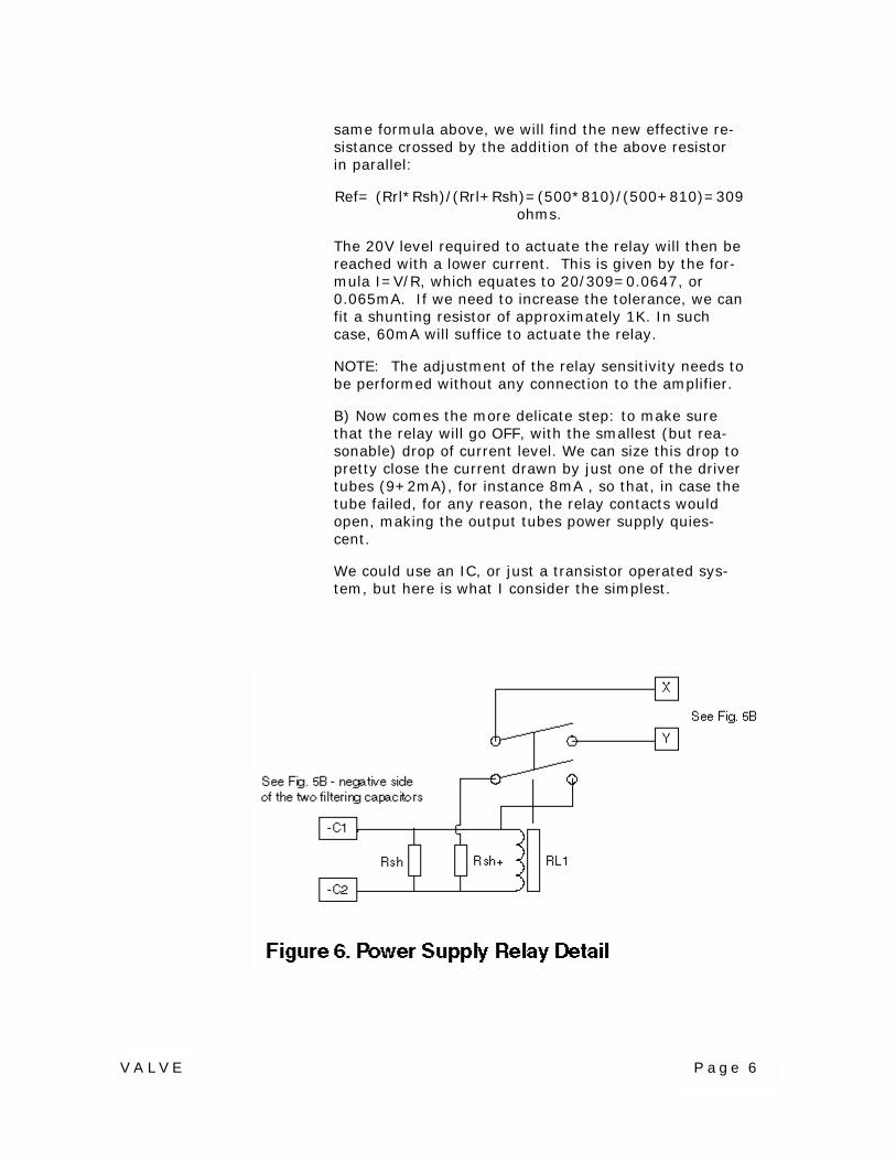
In Figure 6, we have TWO shunting resistors close tothe relay. Rsh- is always connected, and the other,Rsh+ will connect as soon as relay RL1 is actuated.When shunted by a second shunting resistor, the coilgets closer to the voltage below which it fails to be ON.In other words, the threshold value at which the arma-ture is released.
The value of Rsh+ must be calculated in such a waythat, when the current flowing in the coil of RL1 dropsby just about 8mA, the relay contacts open. We couldcalculate this value theoretically, but, instead, let usproceed by trial and error. We will need to connect apotentiometer instead of Rsh+. An approximate valuefor this pot, full scale, could be three or four times theresistance of the relay coil.
The relay coil is already shunted with the resistor Rshthat allows the armature to be attracted at the speci-fied current (in our case 66mA). We now need to findthe value of a the second shunting resistor (Rsh+) thatwill reduce the attraction of the armature to the pointthat, if just 8mA were missing, the armature would bereleased. The procedure requires an adjustable DCsource of, preferably, at least four times the voltagethat operates the coil. Therefore, if the coil operates,nominally at 24 Volts, the source should be 100V.
Moreover, we need to insert a milliammeter, to monitorthe threshold current setting. Its range must be se-lected close to the relay operating current. Below arethe steps:
• Before turning the voltage source ON, set the po-tentiometer to its maximum value.
• Set the DC source to a low value.
• Connect the DC source (in series with the mA) toterminals -C1 and -C2 and turn it ON.
• Increase the voltage applied to the relay, until thearmature is attracted and the contacts close (thisshould happen at 66mA, if Rsh is 810 ohms).
• Reduce the source voltage until the milliammetershows a drop of 8mA (58mA in our case). The ar-mature should still remain attracted.
• Turn the potentiometer to reduce its resistance inohms.
• When the relay releases the armature do not
VALVE Page 8
change the setting, but disconnect everything andmeasure the actual value of the potentiometer re-sistance.
• Said value corresponds to the fixed resistor Rsh+,that can now replace the potentiometer. Betterround the value 5-10% higher, and fit a 22 or 47µF(63V or greater) electrolytic capacitor in parallelwith the relay coil. Both these measures will im-prove the relay stability. Recheck the operation tobe sure it works as desired.
After this work, you can fit the relay as in Figure 5B:The specified drop in the current consumption of thedriver due to a malfunction of the tubes or the resistorsRx, will cut the supply of anode current to the 6C33s.
This safety measure is not compulsory, but it ensures asafer amplifier life. In practice, however, the fuse F1should be enough.
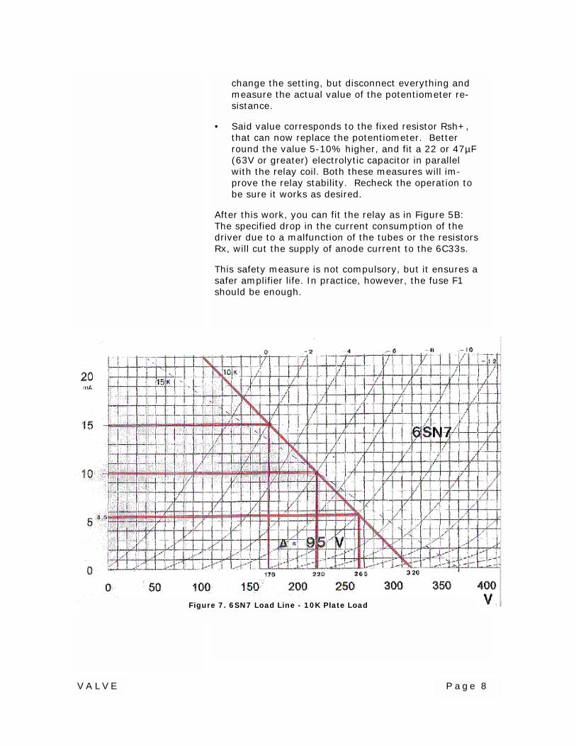
Figure 7. 6SN7 Load Line - 10K Plate Load

VALVE Page 9
Working Conditions of the Driver
When a high power output is needed, a wide swingmust be applied to the 6C33s grids. This means to gofrom almost zero bias to the maximum negative limit.As you know, this is a crowded area, meaning a higherdistortion (see figure 7). This graph shows the load lineof a 10K anode load (plain line). The graph is based,for simplicity, on a swing of-2V to -10V on the grid ofV1b, with an idle current of 10mA, corresponding to ano signal condition bias of minus 6 Volts.
By increasing the anode load to 15K, the load lineslope is modified, as per Figure 8. You will notice that,with the same signal amplitude (from -2V to -10V), thepeak to peak ac voltage across Ra2 increases to about110 Volts, instead of 95V with a 10K load (More infor-mation is available in the RCA Receiving Tube Manual,page 13 onwards). However, with the same anodecurrent of 10mA, the voltage drop across Ra2 increasesfrom 100V to 150V.
The B+ to the driver must be increased somewhat, inorder to restore the potential at V2b’s anode to thesame level. It is very important that I remind you thatthis drop corresponds to the bias applied to the 6C33and that this value is in excess of the requirements.
Figure 8. 6SN7 Load Line - 15K Plate Load
VALVE Page 10
One way to resolve these conflicting situations is repre-sented in figure 9 (attached). The circuit shown ex-plains how, with the addition of an extra high-wattagehigh-voltage resistor (preferably two series-connectedresistors), we can obtain the reduction of the voltagedrop across Ra2, with or without some local negativefeed back.
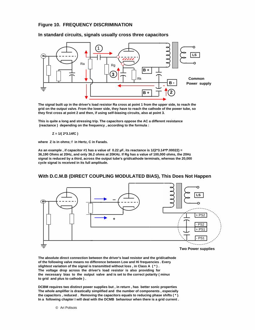
Finally, figure 10 (attached) deals with the merits ofDCMB with respect to frequency discrimination, slewrate, etc.
Please do not hesitate to write for more details or ex-planations.
Ari Polisoisari.polisois at wanadoo.fr
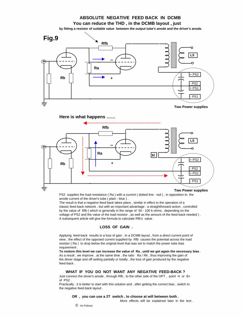
ABSOLUTE NEGATIVE FEED BACK IN DCMB You can reduce the THD , in the DCMB layout , justby fitting a resistor of suitable value between the output tube's anode and the driver's anode.
+
Two Power supplies
Here is what happens ……
Two Power suppliesPS2 supplies the load resistance ( Ra ) with a current ( dotted line - red ) , in opposition to the anode current of the driver's tube ( plain - blue ) .The result is that a negative feed-back takes place , similar in effect to the operation of a classic feed-back network , but with an important advantage : a straightforward action , controlledby the value of Rfb ( which is generally in the range of 50 - 100 k-ohms , depending on the voltage of PS2 and the value of the load resistor , as well as the amount of the feed-back needed ) .A subsequent article will give the formula to calculate Rfb's value .
LOSS OF GAIN .
Applying feed-back results in a loss of gain . In a DCMB layout , from a direct current point of view , the effect of the opposed current supplied by Rfb causes the potential across the load resistor ( Ra ) to drop below the original level that was set to match the power tube bias requirement .To restore this level we can increase the value of Ra , until we get again the necessary bias .As a result , we improve , at the same time , the ratio Ra / Rk , thus improving the gain ofthe driver stage and off-setting partially or totally , the loss of gain produced by the negativefeed-back .
WHAT IF YOU DO NOT WANT ANY NEGATIVE FEED-BACK ? Just connect the driver's anode , through Rfb , to the other side of the OPT , point H or B+of PS2 .Practically , it is better to start with this solution and , after getting the correct bias , switch tothe negative feed-back layout .
OR , you can use a 2T switch , to choose at will between both .More effects will be explained later in the text .
© Ari Polisois
LS
- PS1
+ PS2
- PS2+ PS1
Rfb
LS
- PS1
+ PS2
- PS2+ PS1
Rfb
+
Ra
Rk
Ra
Rk
H
Fig.9
CommonPower supply
+
Two Power supplies
The absolute direct connection between the driver's load resistor and the grid/cathodeof the following valve means no difference between Low and Hi frequencies . Everyslightest variation of the signal is transmitted without loss , in Class A ( * ) .The voltage drop across the driver's load resistor is also providing forthe necessary bias to the output valve and is set to the correct polarity ( minusto grid and plus to cathode ) .
DCBM requires two distinct power supplies but , in return , has better sonic propertiesThe whole amplifier is drastically simplified and the number of components , especiallythe capacitors , reduced . Removing the capacitors equals to reducing phase shifts ( * ).In a following chapter I will deal with the DCMB behaviour when there is a grid current .
© Ari Polisois
cycle signal is received in its full amplitude.
With D.C.M.B (DIRECT COUPLING MODULATED BIAS), This Does Not Happen
As an example , if capacitor #1 has a value of 0.22 µF, its reactance is 1/(2*3.14*f*.00022) = 36,190 Ohms at 20Hz, and only 36.2 ohms at 20KHz. If Rg has a value of 100,000 ohms, the 20Hz signal is reduced by a third, across the output tube's grid/cathode terminals, whereas the 20,000
Z = 1/( 2*3.14fC )
where Z is in ohms; f in Hertz, C in Farads.
they first cross at point 2 and then, if using self-biasing circuits, also at point 3.
This is quite a long and stressing trip. The capacitors oppose the AC a different resistance (reactance ) depending on the frequency , according to the formula :
In standard circuits, signals usually cross three capacitors
Figure 10. FREQUENCY DISCRIMINATION
The signal built up in the driver's load resistor Ra cross at point 1 from the upper side, to reach the grid on the output valve. From the lower side, they have to reach the cathode of the power tube, so
B -
B +
LS
- PS1
+ PS2
- PS2+ PS1
2
3
1 LS
B +
Ra
Rk
Rg

THE FIRST STEP: DCMB By Ari Polisois ©
The First Step: DCMB © A. Polisois
Page 1 of 1
DCMB stands for Direct Coupling Modulated Bias. It is a novel coupling system between valves, with many advantages that will be explained in detail. As every novel circuit, it requires some extra brain work to be fully understood, and it requires personal listening experience to convince. WHY D.C.M.B. ? For over half a century, designers adopted, in most of their audio amplifier circuits, the capacitor/ resistor coupling between one stage and the following. This was made necessary because DC voltage present at the driving tube’s anode had to be blocked. Otherwise, the same DC voltage would rush into the grid of the driven tube and cause damage. The blocking cap was sized to allow an acceptable range of frequencies to pass through it. This range, until some time ago and often even now, was set between 20 and 20,000 cycles. Not long ago, researchers demonstrated that a wider amplified range was beneficial to the quality of reproduction, especially at the high end. For some reason, and opinions differ on the subject, frequencies beyond the human hearing threshold, when included, actively participate to shape the sonic personality of an audio reproduction device, giving it more brilliance and life. Experiments have given more credibility to this belief. Although apparently of a different nature, the following experiment has something to do with it. An amplifier was set to reproduce a low fundamental frequency, 40 Hertz, as well as several of its harmonics (80Hz, 120Hz, 160Hz, etc…) The 40Hz fundamental was removed and, although the spectrum analyser confirmed the absence from the output signal to the speakers, the human ear still could notice its presence. In other words, the harmonics “testified” to the hearing sense that somewhere their fundamental frequency existed. With the same logic, we can accept the fact that the inaudible sounds contribute to the timbre of the musical message. Well, maybe yes, maybe no, but, why amputate the original stream, if we can avoid this questionable operation? Going back to our blocking caps, they really do us a favour with their “harmless” connection, in blocking DC, but they really cost a lot in terms of quality of sound. Our beloved musical message passes through it, and how do they treat him? They squeeze him and modify his personality. With the frequency discrimination they cause, the low frequencies life becomes hard. Let us see how. On the output side of these caps you regularly find the so-called grid leak resistor, whose value is chosen, usually, between 50K to 500k. The cap has an internal resistance to AC, named reactance, determined by the formula: Xc = 1/(2 x 3.14fC), where Xc in ohms, f is Hertz, and C is in Farads. Example: If we use a 0.22µF blocking cap, the calculated reactance is 36.2K at 20Hz, and just 36 Ohms at 20,000 cycles. Supposing we have, at the exit end, a grid leak resistor of 100K, the consequences are: At 20 Hz, over one third of the signal’s amplitude is “eaten” by the cap and the grid leak resistor gets only 73%. At the high end of the spectrum, the signal crosses undisturbed. The voltage amplitude measured across the grid leak resistor is what the output tube gets as driving signal. The unfair behaviour of a cap with respect to low frequencies becomes obvious. The caps can be of excellent quality, still, they all have some kinds of internal vices that disturb the purity of the musical message (foil, dielectric, etc…) Many authors state that even the most expensive, hi-quality, cap is worse than no cap at all.

THE FIRST STEP: DCMB By Ari Polisois ©
The First Step: DCMB © A. Polisois
Page 2 of 2
DCMB belongs to the well known DC coupling family, honest and straightforward, but it has some properties that make it the farthest step in the field. Consider the main dilemmas we have to face: 1. We want to hand over, to the following tube’s grid and cathode, the voltage swing that the driver’s
gain has built across its anode load, and we want to do that instantly and without any kind of fee. 2. We want to prevent the DC, present at this load resistor’s terminals, to force its way through the
grid of the next tube, damaging it. 3. We do not want any capacitor’s interference, such as discrimination between frequencies and
generation of phase shifts. DCMB matches the above three requirements, without unbearable compromises. The enclosed schematics and text will illustrate how this result is achieved. With this novel layout we are going to buy a better quality, paying for it just the price it deserves. Someone could find beforehand the statement of better quality questionable. I would be surprised if this attitude still remained after self experience in building or listening. As stated above, we will have to give something in return and admit that the blocking condenser system is quite safe and handy. No doubt many of the readers are happy with the simple and efficient RC coupling, and prefer to stick to it. I respect their choice. However, I am sure that some others seek quality improvements. Their ambitions will materialize with DCMB. Equal gain on a wider frequency band, faster handling of transients (dynamics), much lower phase shift, are promises that will be kept, provided design and construction respect the rules. Some additional positive points will be discovered, amongst which: ! Improved damping effect in the output tube’s operation, mainly because DCMB eliminates the
need for a fixed bias resistor that burns, in addition, a lot of energy. ! Versatility, because it can be adapted to many output tubes, with minor adjustments. ! Economy, considering the cost of hi-quality caps, worth a bottle of Champagne each. I will not neglect to mention, to be fair, the negative points I am aware of, and I will give the solutions I found to neutralize them, based on my 5 year experience on the subject, encompassing dozens of drivers of this kind and over ten completed amplifiers (PP, SE and SEPP). Better solutions than the ones I used must exist, as well as other undiscovered drawbacks. DCMB is at its early age. The more numerous we are to look at it, the faster this novel system will improve and expand, helping other friends to enjoy their favourite melodies. Ari Polisois April 2002 (*) not surprising that the formula of the phase angle includes capacity and resistance, namely: Phase angle = tan-1(Xc/R), when the cap and the resistor are in series, predominantly our case.

VALVE Page 15
VALVEthe magazine ofthe magazine ofthe magazine ofthe magazine of
astounding soundastounding soundastounding soundastounding sound
Chief Editor and PublisherDan “Dr. Bottlehead” Schmalle
Managing EditorBrad “Stuck inside of Nashville with those Seattle blues again” Brooks
Chief Administrator“Queen Eileen” Schmalle
Resident Smart Guy and Technical EditorPaul “Braniac” JoppaCopy and Art Editor
Jeanine “Yogini Titian” Edwards
VALVEVALVEVALVEVALVEEditorial and Advertising Inquiry
P.O. Box 68093Nashville, TN 37206
by Email: [email protected] Phone: 615-491-1903 CST
VALVE in no way assumes responsibility for anyone harming themselvesthrough exposure to the contents of this magazine. We believe electrons flow
from minus to plus, and that they can kill you along the way if you’re not care-ful. Vacuum tube audio equipment operates at potentially lethal voltages. Al-
ways treat it with respect.Many ideas published in this magazine are untried, and involve the use of po-
tentially dangerous parts and tools. In attempting any idea or project publishedherein, you assume total responsibility for your actions and any harm caused to
yourself or others.
This publication is produced as a service to the audio community and is wholly ownedand published by Bottlehead Corp. The intent of this publication is to offer ideas to in-spire and educate audiophiles in an effort to increase their understanding of the audioequipment that they use and cherish. Blatant copying of the circuits published in thismagazine for use in commercial products shows a complete lack of original thought.
Don’t just copy and distribute stuff without the author’s and publisher’s consent, OK?