Valve Adjustment – Suzuki GS850GT - cycleorings.com · Valve Adjustment – Suzuki GS850GT Hello...
14
Valve Adjustment – Suzuki GS850GT Hello friends, Oh boy! Did I have a ton of fun today! Let me show you what I learned how to do. First, I removed the seat. My GS850GT has two hinges with cotter pins that must be removed. Remove the bolt(s) holding the tank. Disconnect the vacuum line and fuel line from the petcock. Disconnect the fuel gauge wires (the black/yellow and yellow/black wires with bullet connectors). The vent hose can stay with the tank. It will get re-routed back down with all the other hoses in front of the rear tire. After you remove the tank bolt and disconnect the lines, the tank will pull back and lift up for removal.
Transcript of Valve Adjustment – Suzuki GS850GT - cycleorings.com · Valve Adjustment – Suzuki GS850GT Hello...

Valve Adjustment – Suzuki GS850GT
Hello friends,
Oh boy! Did I have a ton of fun today! Let me show you what I learned how to do.
First, I removed the seat. My GS850GT has two hinges with cotter pins that must be removed.
Remove the bolt(s) holding the tank. Disconnect the vacuum line and fuel line from the petcock. Disconnect the fuel gauge wires (the black/yellow and yellow/black wires with bullet connectors). The vent hose can stay with the tank. It will get re-routed back down with all the other hoses in front of the rear tire.
After you remove the tank bolt and disconnect the lines, the tank will pull back and lift up for removal.

Here is a picture with the tank and seat removed. You can see the fuel gauge connections, the fuel line (with the curly wire around it) and the vacuum line (the smaller one).
Next I removed the horns and tucked them up on top of the frame. I didn't have to disconnect them.

OK, next is a picture with the plug wires, horns and breather hose disconnected and tucked up out of the way.
I then removed the valve cover end caps and the ignition cover. I also had to remove my highway bars because I couldn't get to the ignition cover screws.
Then I loosened up all the valve cover bolts (10mm). I tried to take the cover off with the breather attached but didn't have enough room. So I ended up taking the breather off first, then removing the valve cover.
Next I removed the plugs. You must take out the plugs in order to turn the motor (forward-clockwise) using the 19mm bolt under the ignition cover.
Now, where was I? Oh yes.
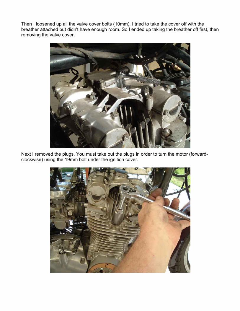
In order to ensure I didn't drop anything into the plug holes, I used bits of shop rag to cover them. If you're not a klutz like me then you might be able to skip this step.
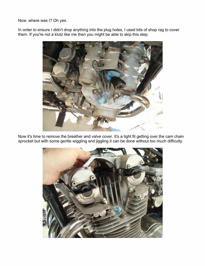
Now it's time to remove the breather and valve cover. It's a tight fit getting over the cam chain sprocket but with some gentle wiggling and jiggling it can be done without too much difficulty.
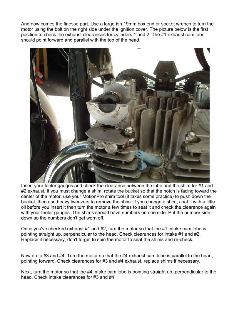
And now comes the finesse part. Use a large-ish 19mm box end or socket wrench to turn the motor using the bolt on the right side under the ignition cover. The picture below is the first position to check the exhaust clearances for cylinders 1 and 2. The #1 exhaust cam lobe should point forward and parallel with the top of the head.
Insert your feeler gauges and check the clearance between the lobe and the shim for #1 and #2 exhaust. If you must change a shim, rotate the bucket so that the notch is facing toward the center of the motor, use your MotionPro shim tool (it takes some practice) to push down the bucket, then use heavy tweezers to remove the shim. If you change a shim, coat it with a little oil before you insert it then turn the motor a few times to seat it and check the clearance again with your feeler gauges. The shims should have numbers on one side. Put the number side down so the numbers don't get worn off.
Once you've checked exhaust #1 and #2, turn the motor so that the #1 intake cam lobe is pointing straight up, perpendicular to the head. Check clearances for intake #1 and #2. Replace if necessary, don't forget to spin the motor to seat the shims and re-check.
Now on to #3 and #4. Turn the motor so that the #4 exhaust cam lobe is parallel to the head, pointing forward. Check clearances for #3 and #4 exhaust, replace shims if necessary.
Next, turn the motor so that the #4 intake cam lobe is pointing straight up, perpendicular to the head. Check intake clearances for #3 and #4.

OK, now the rocket science part is over. Time to start putting it back together. But first, let's get those old half moons out of there. You may wish to use a little gasket sealant on the new half moons.
Now the new valve cover gasket and half moons get put in their places. The valve cover gasket has a front and a back, mind which way you put it on. (Note: Ms. SqDancerLynn1 had an extra gasket because mine didn't get shipped in time. Well, about an hour after I got this put back together, my Real Gasket came in the mail. Drat!)

Ms. SqDancerLynn suggested spraying the gasket with WD40 so that is wasn't so dry. I think that was a very good tip as there were no leaks when I was all done. Here's a picture of the valve cover and the Real Gasket breather gasket, which I did receive in time. Note the wire mesh in the top of the valve cover.
There is also wire mesh on the bottom side of the breather itself. Take care not to lose it.
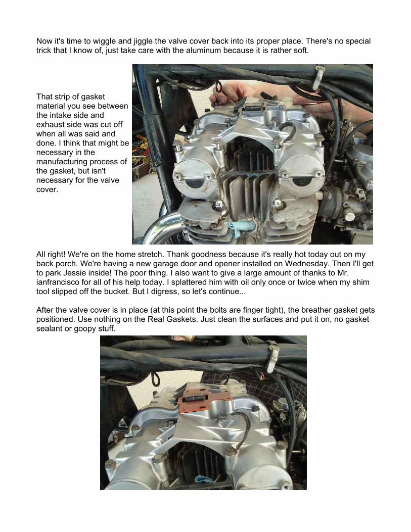
Now it's time to wiggle and jiggle the valve cover back into its proper place. There's no special trick that I know of, just take care with the aluminum because it is rather soft.
That strip of gasket material you see between the intake side and exhaust side was cut off when all was said and done. I think that might be necessary in the manufacturing process of the gasket, but isn't necessary for the valve cover.
All right! We're on the home stretch. Thank goodness because it's really hot today out on my back porch. We're having a new garage door and opener installed on Wednesday. Then I'll get to park Jessie inside! The poor thing. I also want to give a large amount of thanks to Mr. ianfrancisco for all of his help today. I splattered him with oil only once or twice when my shim tool slipped off the bucket. But I digress, so let's continue...
After the valve cover is in place (at this point the bolts are finger tight), the breather gasket gets positioned. Use nothing on the Real Gaskets. Just clean the surfaces and put it on, no gasket sealant or goopy stuff.
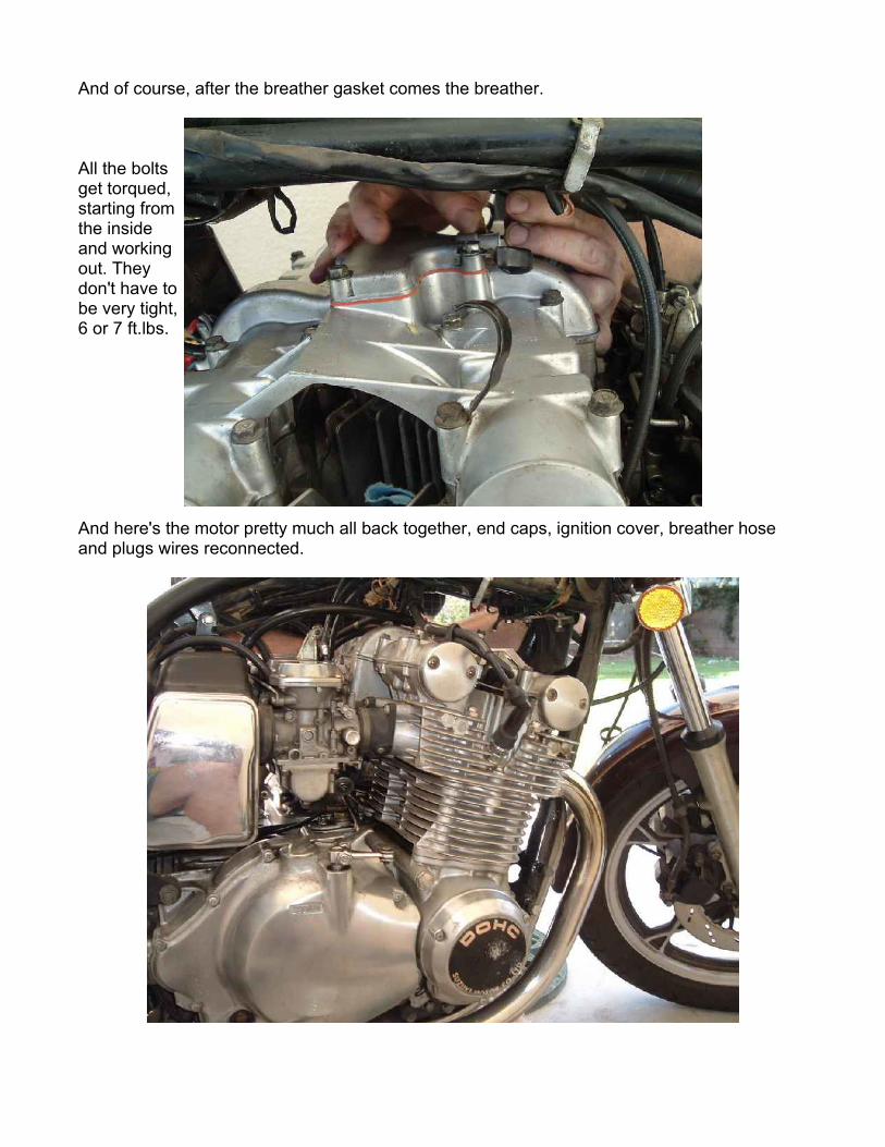
And of course, after the breather gasket comes the breather.
All the bolts get torqued, starting from the inside and working out. They don't have to be very tight, 6 or 7 ft.lbs.
And here's the motor pretty much all back together, end caps, ignition cover, breather hose and plugs wires reconnected.
Next I bolted on the horns, replaced the tank, seat, and highway bars. Sometime early in this process I changed the oil and filter too. It had been 1500 miles so I thought, why not?
I changed 5 shims! The smallest feeler gauge I had was a .04mm and all the shims I changed were less than that. Now I have two exhaust clearances that are at .09mm, but everything else is .06mm and .07mm. Note that factory spec is between .03mm and .08mm for all clearances. Going just a smidgen over, especially for the exhaust valves, will not hurt. It's better to run just a little too loose (but not overly so) than a little too tight. Clearances on these bikes tend to get tighter as they wear.
I took her for a good little test ride. What I noticed was decreased vibration, a smoother ride. Before, my mirrors would start to vibrate at 5500rpm so that everything was a blur. Now my mirrors are clear even past 6000rpm. I didn't get any faster than that on this little test run, but I can tell the valve check made a difference. I don't know if Jessie is any faster, but she sure is smoother.
Additional information:
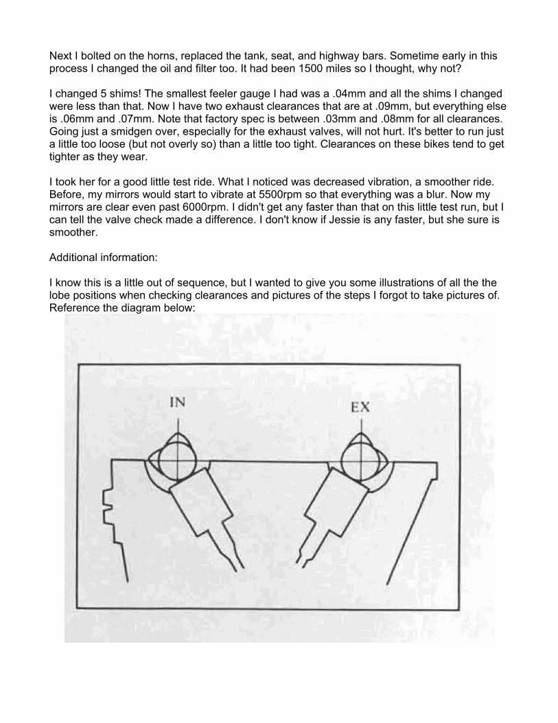
I know this is a little out of sequence, but I wanted to give you some illustrations of all the the lobe positions when checking clearances and pictures of the steps I forgot to take pictures of. Reference the diagram below:
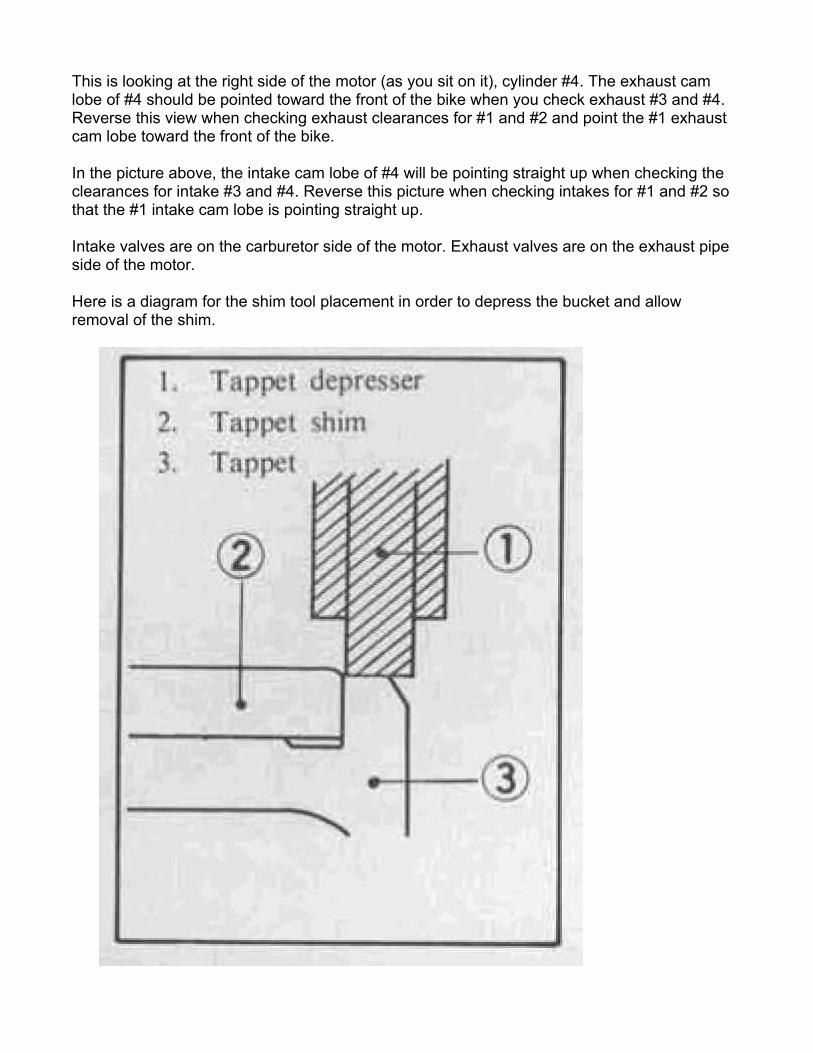
This is looking at the right side of the motor (as you sit on it), cylinder #4. The exhaust cam lobe of #4 should be pointed toward the front of the bike when you check exhaust #3 and #4. Reverse this view when checking exhaust clearances for #1 and #2 and point the #1 exhaust cam lobe toward the front of the bike.
In the picture above, the intake cam lobe of #4 will be pointing straight up when checking the clearances for intake #3 and #4. Reverse this picture when checking intakes for #1 and #2 so that the #1 intake cam lobe is pointing straight up.
Intake valves are on the carburetor side of the motor. Exhaust valves are on the exhaust pipe side of the motor.
Here is a diagram for the shim tool placement in order to depress the bucket and allow removal of the shim.

Place the shim tool (tappet depressor, #1 in the above diagram) next to the cam lobe on the side nearest the center of the engine. Insert the tip as above then take care to keep the tool firmly against the camshaft and perpendicular to the shaft as you apply downward pressure. It takes some practice and if you slip you'll get some oil splatter.
Here's a picture of the beginning of the process.
Once you have the bucket pushed all the way down with the shim tool, the tool will be held in place by the pressure of the valve spring. Hopefully you have remembered to spin the bucket so the notch is pointing up and is accessible. You may need a little pressure (and perhaps a very small flat blade) to break the surface tension seal of the shim in the bucket.
Then remove the shim with tweezers or similar tool. Reference note: The picture below is the intake valve of cylinder #4.
Even if your clearances are within spec, it's a good idea to inventory the shims in your motor. If you know your current shim size, you'll be able to know better what shims you may need for future adjustments. Document all clearances and shim sizes.
Now a little about the shims themselves, sizes, calculating what sizes you need, and extra tools to help you. The shims used in the "2-valve per cylinder" Suzuki motors are 29.5mm in diameter. These motors include the inline 4 cylinder "8 valve" motors and the 2 cylinder "4 valve" motors. (The later GS motors with 16 valves do not use shims.) The shims come in various thicknesses ranging from about 2.20mm to 3.10mm. You can view Z1 Enterprises' selection of shims here. (Note: Z1 also has the best prices on individual shims that I've found online. You can also by a "shim kit" which includes a selection of different sizes. I've also been told that some Suzuki shops will trade shims for a couple of bucks.)
Let's talk about calculating shim replacement sizes. I'll use an example from my experience. When I measured the clearance for the #1 exhaust valve, my .04mm feeler gauge would not fit. So I assumed that the clearance was at .03mm or less. (Note: The spec is between .03mm and .08mm for all clearances.) When I removed that shim I found the number 2.70 on the bottom. This is a 2.70mm shim. In order to gain more clearance I'll have to replace that shim with the next smaller size, or 2.65mm. After I replaced the shim, spun the motor a couple of times to make sure the shim was seated properly, I measured the clearance again and found it was .07mm. Right in spec. That means the original clearance was about .02mm. In effect we added .05mm to the clearance when we replaced the 2.70mm shim with the 2.65mm shim. .05mm plus .02mm equals .07mm. Do you see how the math works?
One more thing about shim sizes. Some shims will be marked with an "X". For example: 2.60X. This means that the shim is actually a little bigger than 2.60mm. This can come in handy when you have a big enough selection of shims and you really want to "dial in" your clearances. Another example from my recent experience was when I measured another clearance at less than .04mm. The shim was a 2.70mm. I dropped in the next size down, 2.65mm. But when I measured the clearance was still barely .04mm. I decided to go down another size, 2.60mm, but that made the clearance too big. So I found a shim marked 2.60X and used it. That brought the clearance for that valve to .07mm, right in spec.
Another handy tool to have is a digital vernier (caliper or micrometer). With it, you can measure each shim for exact thickness. It's also very handy when you find a shim that has had the numbers worn off. Some used shims may have a little wear in them. I found one in my borrowed shim kit that was labeled 2.70mm but measured 2.68mm. I actually used that one to fine tune one of my clearances. Here is an example.
I hope this write-up makes it a little less daunting for those of you who've never checked valve clearances. For those of you familiar with this procedure, please let me know if anything needs editing for clarity or completeness.
My thanks again to Mr. IanFrancisco for his help, and Ms. SqDancerLynn1 for the use of her shim kit and assorted tools and parts.
Thank you for your indulgence,
BassCliff