Value Engineering Award - · PDF fileValue Engineering Award Project Overview State Where...
23
AASHTO VALUE ENGINEERING NOMINATION MOST INNOVATIVE IN DESIGN ENGINEERING Nomination : Study On The Yerba Buena Island/ Self Anchored Suspension Span Contract Of The East Spans Replacement Project San Francisco- Oakland Bay Bridge California Department of Transportation
Transcript of Value Engineering Award - · PDF fileValue Engineering Award Project Overview State Where...

AASHTO VALUE ENGINEERING NOMINATION
MOST INNOVATIVE IN DESIGN ENGINEERING
Nomination: Study On The Yerba Buena Island/ Self
Anchored Suspension Span Contract Of The East Spans Replacement
Project
San Francisco- Oakland Bay Bridge California Department of Transportation

Value Engineering Award Project Overview
State Where Project is located:
In the state of California on San Francisco Bay between the Cities of San Francisco and Oakland.
Name of project: 4th Value Analysis studies for the San Francisco-Oakland Bay Bridge (SFOBB) East Bay
Crossing Replacement.
State Agency Nominated: State of California, Department of Transportation (CALTRANS), District 4.
Names of Agency Members Nominated: Contact Person California Department of Transportation- George Hunter: Phone (916) 653-3538,
or Fax (916) 653-1527
Other participating parties: Terry Hays-Value Analysis Strategies, Inc (760)741-1155 Rodney Curtis- Parson Brinckerhoff Construction Services, Inc (480) 449-7740
Category of award Nomination (Check one) Most Value Added Most Innovative Construction Construction Engineering Engineering√ Process Improvement Process Improvement Brief Project/Proposal Description: In March & April 2002 a value analysis study was carried out on the 90% PS&E submittal package, for the proposed YBI/SAS contract, on one the three proposed contracts for the San Francisco-Oakland Bay Bridge (SFOBB) East Span Replacement project. The SFOBB, carrying 280,000 average daily traffic, is a vital transportation link for the San Francisco Bay area. The purpose of the VA study, the 4th to have been carried out on the SFOBB East Span Replacement Project, was to improve the contracts biddability. The decision to carry out the study, late in the project development process, was largely due to higher than expected recent bids on the adjacent Skyway contract. The YBI/ SAS study was broken up into two independent 100% consultant VA teams and was subsequently followed up by a “Mock Bid” . The “Mock Bid” was an attempt to simulate, to the greatest degree possible, a typical contractor bid estimate. Finally there was a conceptual design activity that involved the VA team. This study is an excellent example of the application of Value Analysis to generate contractual and technical improvements on a project that is technically, politically, and environmentally challenging. ABBREVIATIONS:
SFOBB San Francisco- Oakland Bay Bridge SAS Self Anchored Suspension YBI Yerba Buena Island Caltrans California Department of Transportation
Page 2 of 23
AWARD CRITERIA The following is a listing of how this VA study performed in the established award evaluation criteria
Use of New Technology:
The use of innovative construction methodology using “roll-in/ roll-out” equipment for the East End Tie-In on the South-South detour. This type of technology had never been utilized on the department’s contracts in the past and indicates the willingness to pursue a “risky” operation for which there is no “in-house” experience, and if not successful, would impact a bridge carrying 280,000 vehicles per day.
The use of challenging weldment procedures, a common and heavily discussed topic, was a significant contribution of the VA study, due to the quantity and level of detail. For this reason, the VA study team membership included the developer of the AASHTO/ guidelines on weldments for highway structures. The study proposed numerous recommendations with the intent of specifying weldment requirements and details that are viable in the shop and the field while meeting structural connection requirements.
Out of the Box Thinking:
This study challenged Caltrans standard construction administration procedures by modifying many of our statutorily established payment and mobilization clauses. The use of a contractor design and build contract on the YBI detour contract was contrary to Caltrans’ established design, bid, and build procedure. This decision required the department to take an aggressive, and progressive interpretation on the current state statutes related to construction contracts. Current state statutes prohibit Design-Build contracts on highway projects. Use of a “Mock Bid” to help study and improve the “biddability” and “constructability” of the YBI/SAS contracts.
Increased Value of the Project
The value of a project is determined by its benefits to the traveling public and the surrounding, impacted community and environment. The VA study provided the means to deliver the SFOBB East Spans project in two to three years earlier than had been expected. This, in turn, provides economic and security benefits to the region and state by eliminating the possibility of catastrophic failure of the SFOBB structure within those 2 years of exposure.
Improved operations, safety and/or operations and constructibility
South–South Detour allows the Replacement Project to be delivered in approximately 2- 3 years.
Safety is improved dramatically by replacing a structure susceptible to earthquake damage, carrying 280,000 vehicles per day, 2-3 years earlier. Full Bridge Closures were dramatically decreased and the overall time that traveling public is impacted by construction is reduced by the South-South Detour. Implementation of the south south detour allowed the whole area on the north side of the YBI structure to be available for contractor access and laydown area. This also eliminated the impacts to the historic Admiral’s House belonging to the US Navy by the temporary structure in the original design.
Page 3 of 23
AWARD CRITERIA
Degree that the final project differs from the original design
The contract was originally broken up from one large contract into seven more biddable contract packages. Contractor risk and therefore bonding was decreased. The contract schedule was compressed by approximately two years. The YBI detours were completely redesigned from a north-south to a south-south detour scheme that includes an unusual contract delivery system--contractor designed and built temporary structures.
For more detailed information the VA study proposals and their impacts, please read the subsequent pages.
Page 4 of 23
DESCRIPTION OF THE VA STUDY ACTIVITIES This was the fourth SFOBB VA study completed. The first study took place in July 1996, during the environmental study phase, and led to a replacement strategy of in lieu of the seismic retrofit of the East Spans. Two other studies followed that one, the first was a study on the 30% completed plans in March 1998 and another on the 65% plans in October 2000. This 4th VA Study begun March 2002, consisted of the following activities:
VA Study of the 90% Plans, Specs and Estimates Two independent VA teams (2) to review and 90% PS&E packages. VA Teams analyze the packages, using the VA methodology VA team to provide recommendations Project Manager leading to better construction
bids (include team members knowledgeable in estimating & construction administration). Study Focus: Schedule, Construction Safety, Contractor Risk, Labor/Materials
Availability, Construction Staging/ Traffic Delay, Buy America Clauses, Contract Packaging/ Critical Path
Provide specific recommendations in the following areas: Federalization ( "Buy America") Duration of Advertisement Steel Market Rock Work on Foundations Steel Cables Number of Contractors
Steel Fabrication Requirements W2 Foundation Design Bonding Capacities Working Days Market Conditions (analyze "mega"
projects nationwide/worldwide).
Mock Bid Estimate Analyze the construction support costs for the YBI and SAS contract VA team to develop a "pseudo" bid on the 90% PS&E packages. “Bid” prices for the YBI/SAS contract was developed and another set of bid prices were developed on small broken up contracts. The bid prices developed accounted for market prices, notably for on steel (domestic and international) and on the bonding market that had recently experienced a sharp upturn in prices and restrictions on bonding capacity.
YBI South-South Double Decker Detour feasibility report
A YBI South-South Double Decker Detour feasibility report, completed November 2002, was developed after the conclusion of the VA studies and the Mock Bid preparation. The feasibility report was a quantitative analysis of the double-deck south-south detour concept.. Significant elements of the alternative include a roll-in/roll-out truss configuration at the east-end tie-in to the existing steel truss, and a post-tensioned portal truss configuration at the west-end tie-in to the existing concrete viaduct.
Page 5 of 23

BACKGROUND PROJECT INFORMATION The SFOBB carries 280,000 vehicles daily between Oakland and San Francisco. The East Span Replacement Project proposes to upgrade the level of seismic protection by replacing the existing structure with a new one. Without the project, the SFOBB is at risk of failure of seismic activity predicted over the course of the next twenty to thirty years. The SFOBB East Spans Replacement Project was initiated , along with thousands of other structures susceptible to earthquake damages, after the November 1989 Loma Prieta earthquake. This earthquake failed a span on the existing structures (See Figure 1). The project is located (see Figures 2 , 3 and 4 ) in the San Francisco Oakland Bay area and the SFOBB toll bridge consists of these three main segments: 1. The East Spans, traversing the bay from Oakland to the Yerba Buena Island (YBI) 2. The YBI tunnel which connects the East Spans and the West Spans 3. The West Spans, two in-series suspension bridges with a common anchorage in the middle of the bay between
YBI and San Francisco.
East Span NNoovv.. 11998899
EEaasstt SSppaannss RReeppllaacceemmeenntt PPrroojjeecctt
SAN FRANCISCO
OAKLAND
YBI
Figure 2: Project Site Location
East SpansDamageNovember 1989
Figure 1: Earthquake Damage – East Spans SFOBB
Figure 4: Details on the Existing East Spans and YBI
EAST SPANS
Existing Cantilever Truss Structure over Navigational Trench
Exist YBI Transition Structures
WEST SPANS
YBI
West Spans East Spans
Figure 3: Aerial Photograph ofProject Site
Page 6 of 23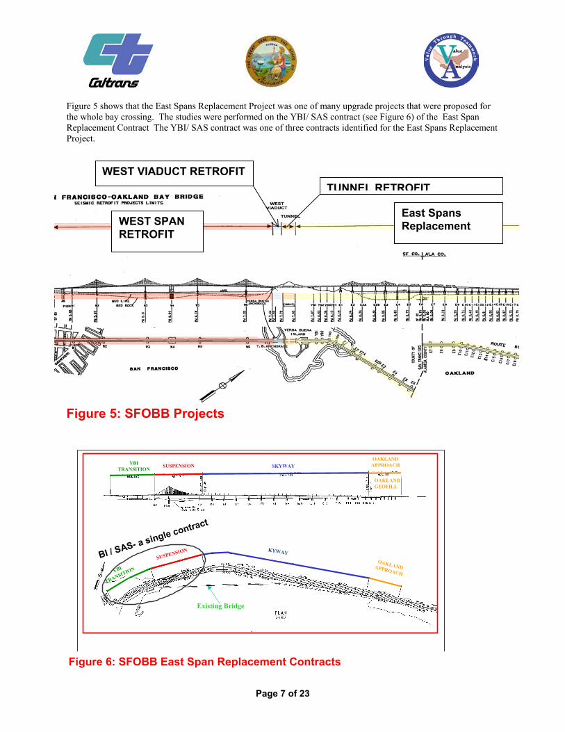
Figure 5 shows that the East Spans Replacement Project was one of many upgrade projects that were proposed for the whole bay crossing. The studies were performed on the YBI/ SAS contract (see Figure 6) of the East Span Replacement Contract The YBI/ SAS contract was one of three contracts identified for the East Spans Replacement Project.
S
Y
WEST VIADUCT RETROFIT
Figure 5: SFOBB Projects
East Spans Replacement
TUNNEL RETROFIT
WEST SPAN RETROFIT
YBI
TRANSITION SKYWAY
KYWAY
YBI
TRANSITION
Existing Bridge
BI / SAS- a single contract
OAKLANDAPPROACH
OAKLANDAPPROACH
OAKLANDGEOFILL
SUSPENSION
SUSPENSION
Figure 6: SFOBB East Span Replacement Contracts
Page 7 of 23

ORIGINAL DESIGN YBI/SAS CONTRACT DETAILS This VA study focused on the SAS and YBI segments, a single contract, of the SFOBB Replacement Project. The Main Span consists of a single-tower, self-anchored suspension span, crossing deep water near Yerba Buena Island, and is designed to complement the West Span of the Bay Bridge. The Main Span includes a single tower between two road decks. The steel tower is a contemporary design of four slender trapezoidal columns connected by linking beams. Two suspender cables drape over the roadway from the tower to the outside of the road decks. Vertical cables attach to the outer edges of the decks. The tower is placed close to Yerba Buena Island, so that the suspender cables on the west side of the tower are shorter than the cables on the east side of the tower. This provides a more engaging asymmetrical design, with the cables sweeping outward from the island toward Oakland.
The new span will carry eastbound and westbound traffic on separate, parallel road decks, each with five traffic lanes and two shoulders. The decks will converge into a double-deck configuration at the approach to the Yerba Buena Island tunnel. The shoulders will improve safety and traffic flow on the span by providing refuge for disabled vehicles. The new span will also include a 15.5-foot wide bicycle/pedestrian path, built one foot above roadway level on the south side of the eastbound deck. Because the decks in the Yerba Buena Island tunnel are stacked, the two parallel decks of the new bridge must converge east of the tunnel. A new eastbound on-ramp from the island to the bridge is also planned for the transition structure. The transition from parallel decks to stacked decks requires complex engineering and detours.
T he following figures are provided to describe the original YBI/ SAS contract that was studied by the VA teams:
Figure 7: Self Anchored Suspension (SAS) Figure 8: SAS Profile Figure 9: SAS Bridge Plan-Cable Layout Figure 10: SAS- Dual Orthotropic Steel Boxes Figure 11: New YBI Transition Structures (3D) Artist
Rendering
Figure 12: New YBI Structures – Work Details Figure 13: YBI Site Details Figure 14: Original Staging Scheme
Page 8 of 23
W2T1 TowerE2 PierFigure 7: Self Anchored Suspension (SAS)
Structural Concrete = 25,000 M3 Bar Reinforcing Steel = 5,200,000 Kg Structural Steel = 52,000,000 Kg
• • •

Pier W2
Pier 1Tower
Elev. +160m
Aprox. OGalong PG Line
Pier E2
12 m
657 m
385 m 80 180 m
Figure 8: SAS Profile
Figure 10: SAS Dual Orthotropic Steel Boxes
Figure 9: SAS Bridge Plan-Cable Layout
Page 9 of 23

T1 founda
Eastbound On-Ramp
W2 foundationWestbound
Transition
Structu
re
Figure 11: New YBI Structures (3D) Artist Rendering
YBI Transition YBI Transition StructureStructure
Temporary Detour Temporary Detour Structures (North Structures (North ––
South)South)
Viaduct ModificationsViaduct Modifications
EB OnEB On--RampRampPermanent StructurePermanent Structure::
HP Piles = 14,500 metersHP Piles = 14,500 meters
W Piles = 10,000 metersW Piles = 10,000 meters
Temp Detour StructureTemp Detour Structure::
Towers & Floor Beams = 5,700,000 kgTowers & Floor Beams = 5,700,000 kg
HP360 Piles = 6,200 metersHP360 Piles = 6,200 meters
Total ConcreteTotal Concrete
Concrete: 55,000 mConcrete: 55,000 m33
Bar Reinforcing Steel: 10,000,000 kgBar Reinforcing Steel: 10,000,000 kg
Figure 12: New YBI Structures- Work Details
Page 10 of 23
Page 11 of 23
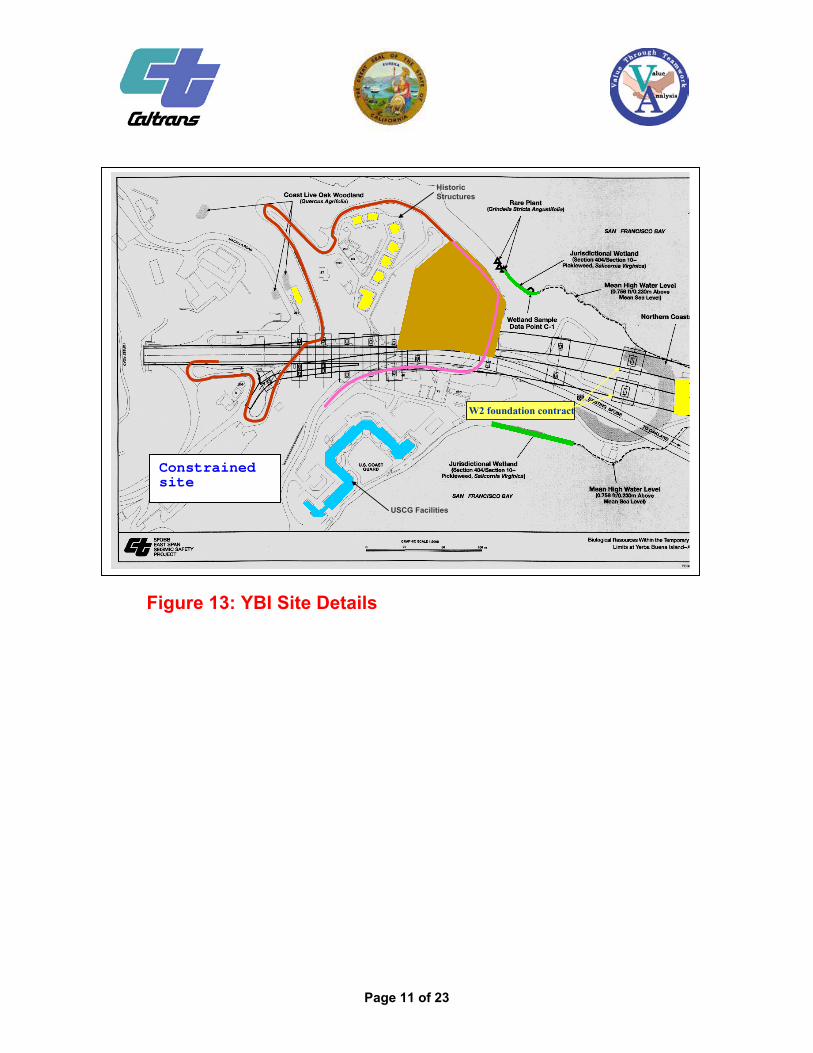
Figure 13: YBI Site Details
USCG Facilities
Historic Structures
W2 foundation contractW2 foundation contract
Constrainedsite
Page 12 of 23
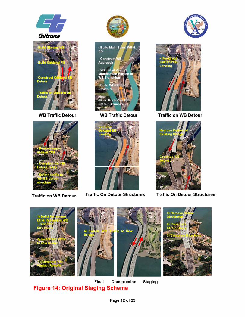
--BBuuiilldd SSkkyywwaayy WWBB --BBuuiilldd OOaakkllaanndd FFiillll --CCoonnssttrruucctt OOaakkllaanndd EEBB DDeettoouurr --TTrraaffffiicc oonn OOaakkllaanndd EEBB DDeettoouurr
-- BBuuiilldd MMaaiinn SSppaann:: WWBB &&EEBB -- CCoonnssttrruucctt WWBB AApppprrooaacchh -- YYBBII IInniittiiaall VViiaadduucctt MMooddiiffiiccaattiioonn PPoorrttiioonn ooff WWBB TTrraannssiittiioonn -- BBuuiilldd WWBB DDeettoouurr SSttrruuccttuurree
-- --
--BBuuiilldd PPoorrttiioonn ooff EEBB DDeettoouurr SSttrruuccttuurree
-- CCoonnssttrruucctt OOaakkllaanndd EEBB LLaannddiinngg
Traffic on WB Detour Traffic On Detour Structures Traffic On Detour Structures
-- RReemmoovvee uuppppeerr ddeecckk aatt YYBB44 -- CCoommpplleettee EEBB YYBBII DDeettoouurr TTiiee--IInn -- SSwwiittcchh ttrraaffffiicc ttoo YYBBII EEBB ddeettoouurr ssttrruuccttuurree
WB Traffic Detour WB Traffic Detour
Remove Portion of Existing Bridge Continue EB Skyway
Continue Oakland EB Landing
Traffic on WB Detour
4) Switch WB Traffic to New Bridge
1) Build Permanent EB & Remaining WB Transition Structures 2) Switch EB traffic to new bridge 3) Complete YBI Viaduct Retrofit
5) Remove Detour Structures 6) Construct EB On-Ramp 7) Complete Bike Path
Figure 14: Original Staging SchemeFinal Construction Staging
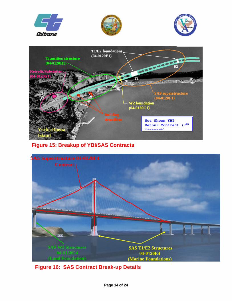
VALUE ANALYSIS PROPOSALS Contract Segregations One the key reasons that Caltrans management requested the VA study was to investigate ways to increase the bidding pool and thereby lower the bid prices due according to the law of supply and demand. The VA teams recommended that the YBI/SAS contract be divided into smaller contracts to decrease the contract sizes to attract bidders with less financial resources. Furthermore, this would make the project mare attractive to surety companies by lowering risk. Contracts were packaged according to typical construction methods and craft labor. The VA Team suggested segregating the land-based foundation work, the marine-based large foundation and the suspension superstructure work into separate contracts. Figures 15 and 16 graphically describe the original YBI/ SAS contracts, respectively. In total the one YBI/SAS contract was broken up into seven contract packages that were created following the VA study recommendation: The following describes each individual contract on the YBI portion: YBI Building Demolition(R/W) a contract to remove three USCG buildings and one state building executed as a right-of-way service
contract YBI Substation & Viaduct Retrofit a contract to construct a replacement electrical substation on YBI near the westbound on-ramp and
complete relatively simple bridge retrofit work near the YBI tunnel (this work is combined due to the close proximity of the work)
YBI Temp Detour Structures a contract to construct the temporary detours to accommodate the permanent YBI Transition Structures
YBI Permanent Transition Structures a contract to construct the permanent bridges on YBI
The following describes each individual contract on the SAS portion:
SAS T1/E2 Structures a contract to construct the Self-Anchored Suspension bridge in-bay foundations, the main tower (T1) and
pier E2 just to the east of YBI SAS W2 Structures a contract to construct the Self-Anchored Suspension bridge land-based foundation, pier W2
SAS Superstructures a contract to construct the tower and superstructure of the Self-Anchored Suspension bridge.
The SAS contracts were modified to allow alternative bidding as follows
1st bid by each construction team submitting must incorporate a domestic supply of steel If, and only if, a responsive 1st bid is submitted, a 2nd alternative bid may be submitted by that
construction team that incorporates an international supply of steel. The Project Manager requested and received an exemption on the bridge cables and the cast steel items for the SAS Superstructures contract. This exemption is estimated to save $32 million by relying on less expensive foreign steel suppliers. Furthermore the more reliable and earlier availability in furnishing the steel from established foreign suppliers increases the likelihood of a timely and succesful completion of the project within the expected completion date.
Page 13 of 23
Page 14 of 24
SAS T1/E2 Structures04-0120E4
(Marine Foundations)
SAS Superstructure 04-0120F4Contract
SAS W2 Structures04-0120C4
(Land Foundation)
Figure 16: SAS Contract Break-up Details
Yerba Buena Island
T1/E2 foundations (04-0120E1)
T1
E2
T1/E2 foundations (04-0120E1)
T1
E2
W2 foundation (04-0120C1)W2 foundation (04-0120C1)W2 foundation (04-0120C1)
Building demolitionBuilding demolition
Transition structure (04-0120H1)Transition structure (04-0120H1)
SAS superstructure (04-0120F1)SAS superstructure (04-0120F1)
Retrofit/Substation (04-0120G1)Retrofit/Substation (04-0120G1)
Figure 15: Breakup of YBI/SAS Contracts
Not Shown YBI Detour Contract (7th Contract)

South – South Detour Alternative Proposal One of the key recommendations of the VA study was to change the detour configuration on the YBI Island. The VA report suggested proposed double-deck detour structure on only the south side of the existing YBI Structure as opposed to the original North–South detour (refer to Figures 12 and 14 for details on the original detour configurations). One of the key drawbacks of the original detour was that it required the completion of the SAS structure before any substantial YBI work could progress. The VA team’s south south double-decker detour scheme divorced the YBI structures construction from this staging requirement. This south south detour proposal had also been recommended in previous VA studies, however was never seriously investigated by the project development team because of schedule restraints and the amount of technical elaboration required at the west end and east end tie-in connections. This time, however the project development team requested that VA team develop a conceptual design to evaluate the technical viability of the proposal. A feasibility study was carried out by key VA team members and augmented with additional technical specialists addressing the structural details and a traffic handling at the east end and west end tie-ins connections. This feasibility was completed on November 4, 2002, finding the detour feasible with respect to preliminary geometrics, structural framing, constructibility and staging issues at the critical west end tie-in. Figures 17-19 provide details on the general detour concepts. The west end tie-in, as shown in Figures 20-22, can be constructed via the currently approved bridge lane closure charts as opposed to the partial and full bridge closures as in the original detour scheme. The existing roadway preparation work drives these lane closures rather than the construction of the detour structure itself, which is envisioned to be staged in parallel with roadway work. The east end connection was proposed via a double-deck truss roll-in/roll-out solution to install the transition structure between the detour viaducts and the existing structure’s double-deck trusses was the final solution for east end tie-in connection (see Figures 23 and 24). In the south south detour scheme, there is onlv one full bridge closure associated with the re-routing of traffic from the existing to the new detour structure which can occur simultaneous with the roll-in roll-out east end tie-in maneuver. The roll-in/roll-out maneuver dictates the length of this bridge closure, estimated to be only 8 hours of bridge closure. This is a substantial benefit when contrasted with the 120 hours of full bridge closure anticipated for original detour scheme. The west end tie-in required 960 hours of closures during off peak hours Based on this feasibility study, it appeared that the opportunity for opening the East Spans Replacement Project in 2 –3 years less, as stated by the original VA Team proposal is reasonable. The project development team used a more conservative estimate of 1-2 years. By shifting both EB and WB detour maneuvers to the south side of the existing bridge, staging and laydown areas for the contractors working on the new Self-Anchored Suspension (SAS) bridge to the north of the existing bridge will be less constrained. Furthermore, this schedule compression increases the seismic safety for the bridge travelers and decreases the risk of negative economic impacts related to losing a vital transportation link between the San Francisco and Oakland.
Page 15 of 23
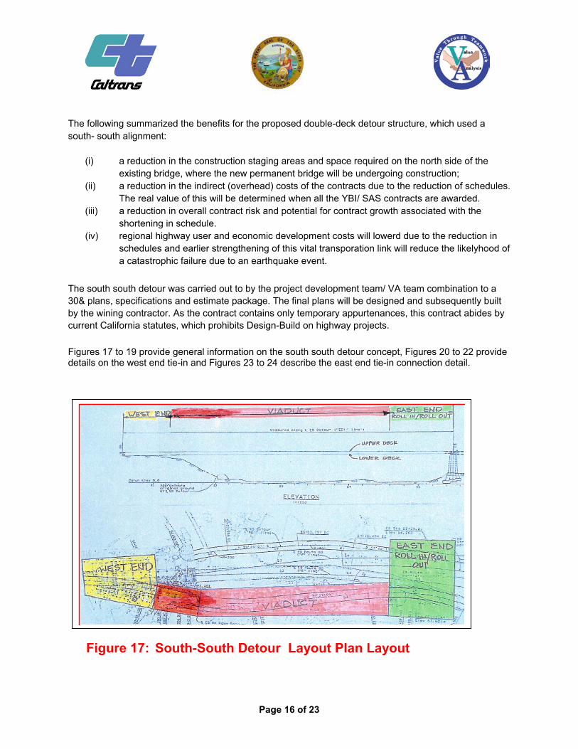
The following summarized the benefits for the proposed double-deck detour structure, which used a south- south alignment:
(i) a reduction in the construction staging areas and space required on the north side of the existing bridge, where the new permanent bridge will be undergoing construction;
(ii) a reduction in the indirect (overhead) costs of the contracts due to the reduction of schedules. The real value of this will be determined when all the YBI/ SAS contracts are awarded.
(iii) a reduction in overall contract risk and potential for contract growth associated with the shortening in schedule.
(iv) regional highway user and economic development costs will lowerd due to the reduction in schedules and earlier strengthening of this vital transporation link will reduce the likelyhood of a catastrophic failure due to an earthquake event.
The south south detour was carried out to by the project development team/ VA team combination to a 30& plans, specifications and estimate package. The final plans will be designed and subsequently built by the wining contractor. As the contract contains only temporary appurtenances, this contract abides by current California statutes, which prohibits Design-Build on highway projects. Figures 17 to 19 provide general information on the south south detour concept, Figures 20 to 22 provide details on the west end tie-in and Figures 23 to 24 describe the east end tie-in connection detail.
Figure 17: South-South Detour Layout Plan Layout
Page 16 of 23

Page 17 of 23
Note:Original East Spans YBIcontracts delivery was estimateby the VA Team in Year 2009
Figure 19: South-South Detour Schedule
Figure 18: South-South Detour Typical Section Double- Decker Detail

Page 18 of 23
Figure 20: South South Detour/ West End Tie In Geometrics Lower and Upper Deck
Geometrics – Lower Deck
Geometrics – Upper Deck

Page 19 of 23
Cantilevers ProppedCantilevers
PortalFrames
Figure 21: South South Detour/ West End Tie In Geometrics – Plan View Framing
Page 20 of 23
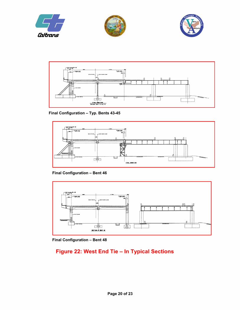
Figure 22: West End Tie – In Typical Sections
Final Configuration – Bent 48
Final Configuration – Bent 46
Final Configuration – Typ. Bents 43-45
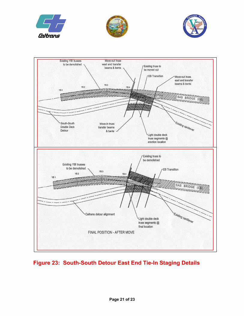
Figure 23: South-South Detour East End Tie-In Staging Details
Page 21 of 23
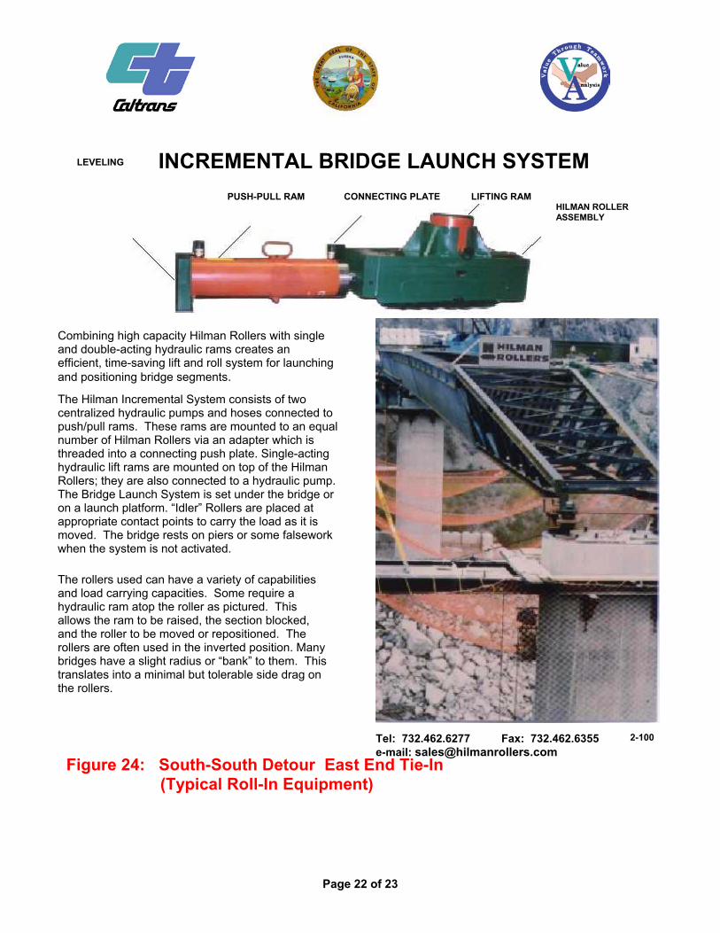
INCREMENTAL BRIDGE LAUNCH SYSTEM LEVELING
PUSH-PULL RAM CONNECTING PLATE LIFTING RAM HILMAN ROLLER ASSEMBLY
Combining high capacity Hilman Rollers with single and double-acting hydraulic rams creates an efficient, time-saving lift and roll system for launching and positioning bridge segments.
The Hilman Incremental System consists of two centralized hydraulic pumps and hoses connected to push/pull rams. These rams are mounted to an equal number of Hilman Rollers via an adapter which is threaded into a connecting push plate. Single-acting hydraulic lift rams are mounted on top of the Hilman Rollers; they are also connected to a hydraulic pump. The Bridge Launch System is set under the bridge or on a launch platform. “Idler” Rollers are placed at appropriate contact points to carry the load as it is moved. The bridge rests on piers or some falsework when the system is not activated.
The rollers used can have a variety of capabilities and load carrying capacities. Some require a hydraulic ram atop the roller as pictured. This allows the ram to be raised, the section blocked, and the roller to be moved or repositioned. The rollers are often used in the inverted position. Many bridges have a slight radius or “bank” to them. This translates into a minimal but tolerable side drag on the rollers.
Tel: 732.462.6277 Fax: 732.462.6355 e-mail: [email protected]
Figure 24: South-South Detour East End Tie-In (Typical Roll-In Equipment)
2-100
Page 22 of 23
Page 23 of 23
Other Changes Additional recommendations implemented in YBI/SAS contracts include the following modifications to decrease contractor risk and financial burden:
additional connections within SAS steel tower to make it more constructible. modified standard (boiler plate) mobilization payment specification modified and improved steel fabrication specification and weldments included partial payment for responsive submittals for YBI detour contract (to compensate heavy engineering development costs) added payments for materials on hand lowered contractor $$ liability cap associated with potential EQ damage to work (lesser of $20 million cap or 5% of contract amount).