VALU-BEAM 912 …info.bannerengineering.com/cs/groups/public/documents/literature/... · AC- and...
12
Datasheet AC- and DC-powered sensors with solid-state outputs To view or download the latest technical information about this product, including specifications, dimensions, accessories, and wiring, see http://www.bannerengineering.com. • Choose models for 10 to 30 V dc or 24 to 250 V ac operation • DC models have bipolar solid-state outputs: one NPN (sinking) and one PNP (sourcing) • AC models have an SPST solid-state output rated for up to 3/4 amp with simple 2-wire hookup • All models have a rear panel sensitivity adjustment and light/dark operate switch • DC models include Banner’s Alignment Indicating Device (AID ™ ) system • Choose models with integral 2 m (6.5 ft) cable or Mini-style QD (quick-disconnect) connector; 9 m (30 ft) cables are also available WARNING: Not To Be Used for Personnel Protection Never use this device as a sensing device for personnel protection. Doing so could lead to serious injury or death. This device does not include the self-checking redundant circuitry necessary to allow its use in personnel safety applications. A sensor failure or malfunction can cause either an energized or de-energized sensor output condition. Models To order the 9 m (30 ft) cable model, add the suffix "W/30" to the cabled model number. For example, SMA91E W/30. A model with a QD connector requires a mating cable; see Quick-Disconnect Cables on page 10. Opposed Mode Emitter (E) and Receiver (R) Models OPPOSED Infrared, 880 nm Models Range Cable Supply Voltage Output Type SMA91E 60 m (200 ft) 2 m (6.5 ft) 10 to 250 V ac/dc - SMA91EQD 3-pin Mini QD SM91R 2 m (6.5 ft) 10 to 30 V dc Bipolar NPN/PNP SM91RQD 4-pin Mini QD SM2A91R 2 m (6.5 ft) 24 to 250 V ac SPST SCR Solid-state 2-wire SM2A91RQD 3-pin Mini QD SMA91ESR 3 m (10 ft) 2 m (6.5 ft) 10 to 250cV ac/dc - SMA91ESRQD 3-pin Mini QD SM91RSR 2 m (6.5 ft) 10 to 30 V dc Bipolar NPN/PNP SM91RSRQD 4-pin Mini QD SM2A91RSR 2 m (6.5 ft) 24 to 250 V ac SPST SCR Solid-state 2-wire SM2A91RSRQD 3-pin Mini QD VALU-BEAM ® 912 Series Original Document 03467 Rev. G 3 October 2016 03467
Transcript of VALU-BEAM 912 …info.bannerengineering.com/cs/groups/public/documents/literature/... · AC- and...

DatasheetAC- and DC-powered sensors with solid-state outputs
To view or download the latest technical information about this product, including specifications, dimensions, accessories,and wiring, see http://www.bannerengineering.com.
• Choose models for 10 to 30 V dc or 24 to 250 V ac operation• DC models have bipolar solid-state outputs: one NPN (sinking) and
one PNP (sourcing)• AC models have an SPST solid-state output rated for up to 3/4 amp
with simple 2-wire hookup• All models have a rear panel sensitivity adjustment and light/dark
operate switch• DC models include Banner’s Alignment Indicating Device (AID™)
system• Choose models with integral 2 m (6.5 ft) cable or Mini-style QD
(quick-disconnect) connector; 9 m (30 ft) cables are also available
WARNING: Not To Be Used for Personnel Protection
Never use this device as a sensing device for personnel protection. Doing so could lead toserious injury or death. This device does not include the self-checking redundant circuitry necessaryto allow its use in personnel safety applications. A sensor failure or malfunction can cause either anenergized or de-energized sensor output condition.
ModelsTo order the 9 m (30 ft) cable model, add the suffix "W/30" to the cabled model number. For example, SMA91E W/30.
A model with a QD connector requires a mating cable; see Quick-Disconnect Cables on page 10.
Opposed Mode Emitter (E) and Receiver (R) Models
OPPOSED Infrared, 880 nm
Models Range Cable Supply Voltage Output Type
SMA91E
60 m (200 ft)
2 m (6.5 ft)10 to 250 V ac/dc -
SMA91EQD 3-pin Mini QD
SM91R 2 m (6.5 ft)10 to 30 V dc Bipolar NPN/PNP
SM91RQD 4-pin Mini QD
SM2A91R 2 m (6.5 ft)24 to 250 V ac SPST SCR Solid-state 2-wire
SM2A91RQD 3-pin Mini QD
SMA91ESR
3 m (10 ft)
2 m (6.5 ft)10 to 250cV ac/dc -
SMA91ESRQD 3-pin Mini QD
SM91RSR 2 m (6.5 ft)10 to 30 V dc Bipolar NPN/PNP
SM91RSRQD 4-pin Mini QD
SM2A91RSR 2 m (6.5 ft)24 to 250 V ac SPST SCR Solid-state 2-wire
SM2A91RSRQD 3-pin Mini QD
VALU-BEAM® 912 Series
Original Document03467 Rev. G
3 October 2016
03467
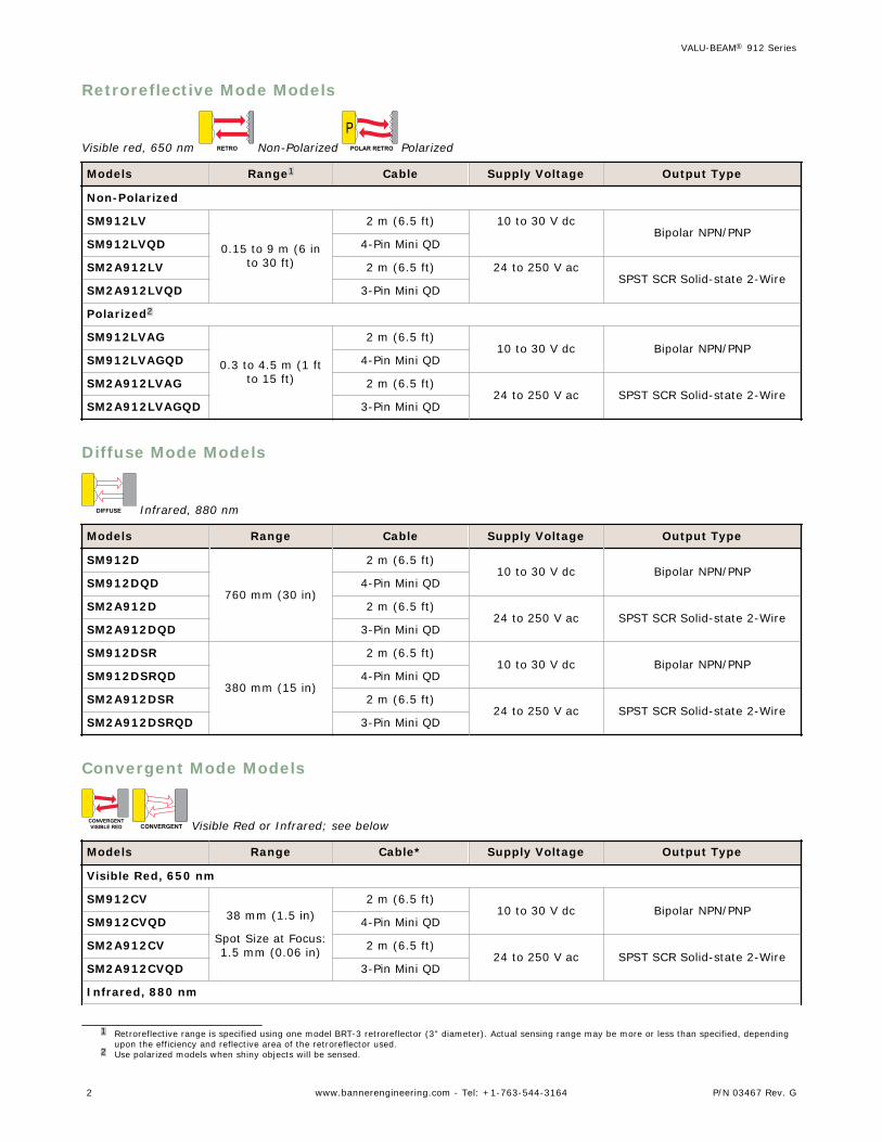
Retroreflective Mode Models
Visible red, 650 nm RETRO Non-Polarized P
POLAR RETRO Polarized
Models Range1 Cable Supply Voltage Output Type
Non-Polarized
SM912LV
0.15 to 9 m (6 into 30 ft)
2 m (6.5 ft) 10 to 30 V dcBipolar NPN/PNP
SM912LVQD 4-Pin Mini QD
SM2A912LV 2 m (6.5 ft) 24 to 250 V acSPST SCR Solid-state 2-Wire
SM2A912LVQD 3-Pin Mini QD
Polarized2
SM912LVAG
0.3 to 4.5 m (1 ftto 15 ft)
2 m (6.5 ft)10 to 30 V dc Bipolar NPN/PNP
SM912LVAGQD 4-Pin Mini QD
SM2A912LVAG 2 m (6.5 ft)24 to 250 V ac SPST SCR Solid-state 2-Wire
SM2A912LVAGQD 3-Pin Mini QD
Diffuse Mode Models
DIFFUSE Infrared, 880 nm
Models Range Cable Supply Voltage Output Type
SM912D
760 mm (30 in)
2 m (6.5 ft)10 to 30 V dc Bipolar NPN/PNP
SM912DQD 4-Pin Mini QD
SM2A912D 2 m (6.5 ft)24 to 250 V ac SPST SCR Solid-state 2-Wire
SM2A912DQD 3-Pin Mini QD
SM912DSR
380 mm (15 in)
2 m (6.5 ft)10 to 30 V dc Bipolar NPN/PNP
SM912DSRQD 4-Pin Mini QD
SM2A912DSR 2 m (6.5 ft)24 to 250 V ac SPST SCR Solid-state 2-Wire
SM2A912DSRQD 3-Pin Mini QD
Convergent Mode Models
CONVERGENTVISIBLE RED CONVERGENT Visible Red or Infrared; see below
Models Range Cable* Supply Voltage Output Type
Visible Red, 650 nm
SM912CV38 mm (1.5 in)
Spot Size at Focus:1.5 mm (0.06 in)
2 m (6.5 ft)10 to 30 V dc Bipolar NPN/PNP
SM912CVQD 4-Pin Mini QD
SM2A912CV 2 m (6.5 ft)24 to 250 V ac SPST SCR Solid-state 2-Wire
SM2A912CVQD 3-Pin Mini QD
Infrared, 880 nm
1 Retroreflective range is specified using one model BRT-3 retroreflector (3" diameter). Actual sensing range may be more or less than specified, dependingupon the efficiency and reflective area of the retroreflector used.
2 Use polarized models when shiny objects will be sensed.
VALU-BEAM® 912 Series
2 www.bannerengineering.com - Tel: +1-763-544-3164 P/N 03467 Rev. G

Models Range Cable* Supply Voltage Output Type
SM912C
38 mm (1.5 in)
2 m (6.5 ft)10 to 30 V dc Bipolar NPN/PNP
SM912CQD 4-Pin Mini QD
SM2A912C 2 m (6.5 ft)24 to 250 V ac SPST SCR Solid-state 2-Wire
SM2A912CQD 3-Pin Mini QD
Glass Fiber Optic Individual Emitter or Receiver Models
GLASS FIBERTWO SENSORS Infrared, 880 nm
Use where the separation between emitting and receiving fibers is more than a few feet, or where it is inconvenient to runboth fibers from a single sensor. Watertight o-ring-sealed sensor/fiber interface.
Models Range Cable Supply Voltage Output Type
SMA91EF
Range varies withfiber used
2 m (6.5 ft)10 to 250 V ac/dc –
SMA91EFQD 3-Pin Mini QD
SM91RF 2 m (6.5 ft)10 to 30 V dc Bipolar NPN/PNP
SM91RFQD 4-Pin Mini QD
SM2A91RF 2 m (6.5 ft)24 to 250 V ac SPST SCR Solid-state 2-Wire
SM2A91RFQD 3-Pin Mini QD
Glass Fiber Optic Models
GLASS FIBER Infrared, 880 nm
Watertight o-ring-sealed sensor/fiber interface.
Models Range Cable Supply Voltage Output Type
SM912F
Range varies withsensing mode andfiber optics used
2 m (6.5 ft)10 to 30 V dc Bipolar NPN/PNP
SM912FQD 4-Pin Mini QD
SM2A912F 2 m (6.5 ft)24 to 250 V ac SPST SCR Solid-state 2-Wire
SM2A912FQD 3-Pin Mini QD
DC Wiring Diagrams
Emitters - Cabled
bn
bu
+
–10-250V ac/dc
Emitters - QD (3-Pin Mini-Style)
bn
bk
bu 10-250V ac/dc+
–
3-Pin Mini-Style Pinout (CableConnector Shown)
23
1 1 = Black
2 = Brown
3 = Blue
VALU-BEAM® 912 Series
P/N 03467 Rev. G www.bannerengineering.com - Tel: +1-763-544-3164 3
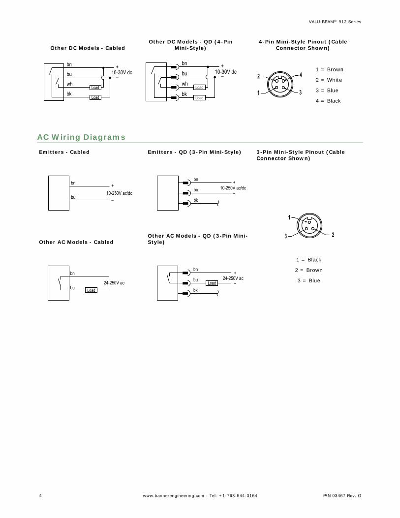
Other DC Models - Cabled
bn
wh
bu+
–
bkLoad
Load
10-30V dc
Other DC Models - QD (4-PinMini-Style)
bn
wh
bu+
–
bkLoad
Load
10-30V dc
4-Pin Mini-Style Pinout (CableConnector Shown)
4
31
21 = Brown
2 = White
3 = Blue
4 = Black
AC Wiring Diagrams
Emitters - Cabled
bn
bu
+
–10-250V ac/dc
Emitters - QD (3-Pin Mini-Style)
bn
bk
bu 10-250V ac/dc+
–
3-Pin Mini-Style Pinout (CableConnector Shown)
23
1
1 = Black
2 = Brown
3 = Blue
Other AC Models - Cabled
bn
bu Load24-250V ac
Other AC Models - QD (3-Pin Mini-Style)
bn
bk
bu 24-250V acLoad
+
–
VALU-BEAM® 912 Series
4 www.bannerengineering.com - Tel: +1-763-544-3164 P/N 03467 Rev. G
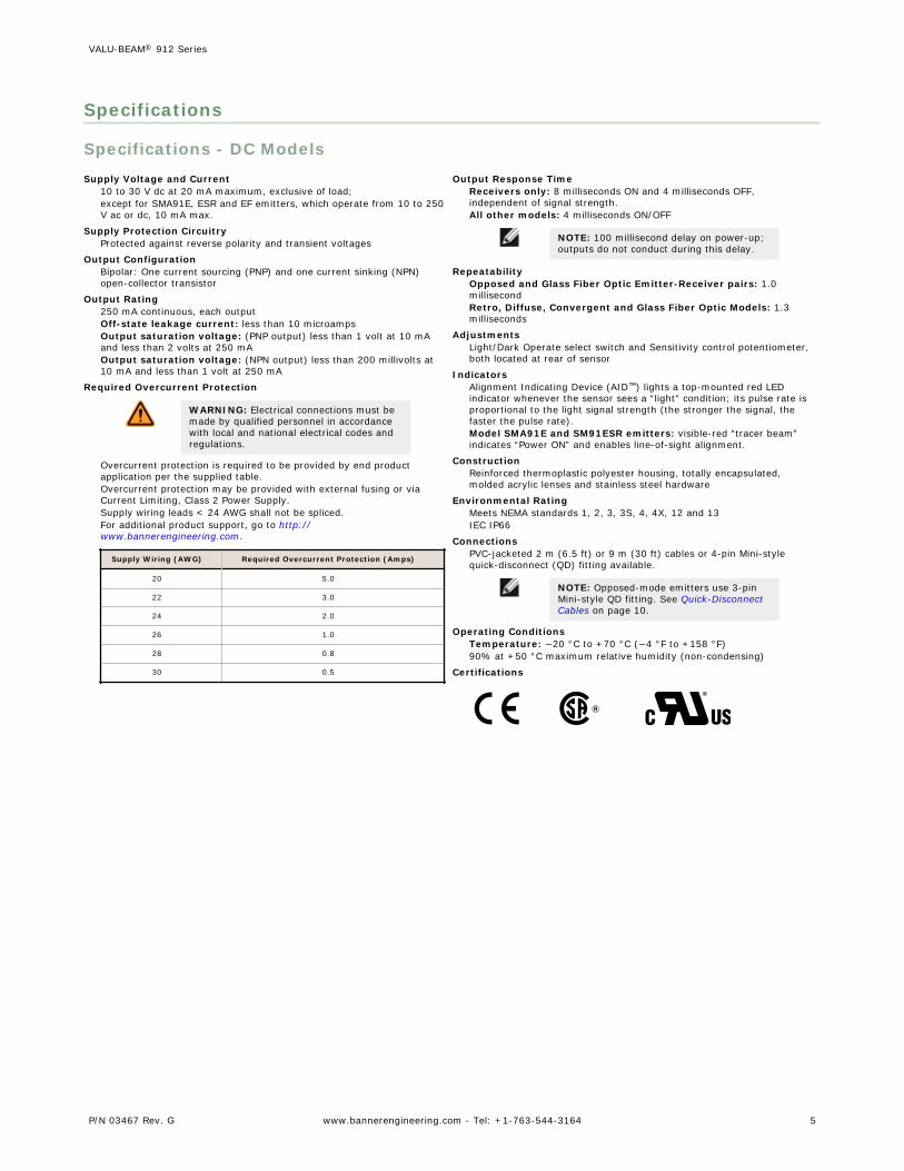
Specifications
Specifications - DC ModelsSupply Voltage and Current
10 to 30 V dc at 20 mA maximum, exclusive of load;except for SMA91E, ESR and EF emitters, which operate from 10 to 250V ac or dc, 10 mA max.
Supply Protection CircuitryProtected against reverse polarity and transient voltages
Output ConfigurationBipolar: One current sourcing (PNP) and one current sinking (NPN)open-collector transistor
Output Rating250 mA continuous, each outputOff-state leakage current: less than 10 microampsOutput saturation voltage: (PNP output) less than 1 volt at 10 mAand less than 2 volts at 250 mAOutput saturation voltage: (NPN output) less than 200 millivolts at10 mA and less than 1 volt at 250 mA
Required Overcurrent Protection
WARNING: Electrical connections must bemade by qualified personnel in accordancewith local and national electrical codes andregulations.
Overcurrent protection is required to be provided by end productapplication per the supplied table.Overcurrent protection may be provided with external fusing or viaCurrent Limiting, Class 2 Power Supply.Supply wiring leads < 24 AWG shall not be spliced.For additional product support, go to http://www.bannerengineering.com.
Supply Wiring (AWG) Required Overcurrent Protection (Amps)
20 5.0
22 3.0
24 2.0
26 1.0
28 0.8
30 0.5
Output Response TimeReceivers only: 8 milliseconds ON and 4 milliseconds OFF,independent of signal strength.All other models: 4 milliseconds ON/OFF
NOTE: 100 millisecond delay on power-up;outputs do not conduct during this delay.
RepeatabilityOpposed and Glass Fiber Optic Emitter-Receiver pairs: 1.0millisecondRetro, Diffuse, Convergent and Glass Fiber Optic Models: 1.3milliseconds
AdjustmentsLight/Dark Operate select switch and Sensitivity control potentiometer,both located at rear of sensor
IndicatorsAlignment Indicating Device (AID™) lights a top-mounted red LEDindicator whenever the sensor sees a “light” condition; its pulse rate isproportional to the light signal strength (the stronger the signal, thefaster the pulse rate).Model SMA91E and SM91ESR emitters: visible-red “tracer beam”indicates “Power ON” and enables line-of-sight alignment.
ConstructionReinforced thermoplastic polyester housing, totally encapsulated,molded acrylic lenses and stainless steel hardware
Environmental RatingMeets NEMA standards 1, 2, 3, 3S, 4, 4X, 12 and 13IEC IP66
ConnectionsPVC-jacketed 2 m (6.5 ft) or 9 m (30 ft) cables or 4-pin Mini-stylequick-disconnect (QD) fitting available.
NOTE: Opposed-mode emitters use 3-pinMini-style QD fitting. See Quick-DisconnectCables on page 10.
Operating ConditionsTemperature: −20 °C to +70 °C (−4 °F to +158 °F)90% at +50 °C maximum relative humidity (non-condensing)
Certifications
VALU-BEAM® 912 Series
P/N 03467 Rev. G www.bannerengineering.com - Tel: +1-763-544-3164 5

Specifications - AC ModelsSupply Voltage and Current
24 to 250 V ac (50/60 Hz);except for SMA91E, ESR and EF emitters, which operate from 10 to 250V ac or dc
Supply Protection CircuitryProtected against transient voltages
Output ConfigurationSPST SCR solid-state relay with either normally closed or normallyopen contact (light/dark operate selectable); 2-wire hookup
Output RatingMinimum load current 10 mA, max. steady-state load capability 750mA to 50 °C ambient (122 °F), 500 mA to 70 °C ambient (158 °F)Inrush capability: 4 amps for 1 second (non-repetitive)Off-state leakage: current less than 1.7 mA rmsOn-state voltage drop: ≤ 5 volts rms at 750 mA load, ≤ 10 volts rmsat 15 mA load
Output Protection CircuitryProtected against false pulse on power-up
Required Overcurrent Protection
WARNING: Electrical connections must bemade by qualified personnel in accordancewith local and national electrical codes andregulations.
Overcurrent protection is required to be provided by end productapplication per the supplied table.Overcurrent protection may be provided with external fusing or viaCurrent Limiting, Class 2 Power Supply.Supply wiring leads < 24 AWG shall not be spliced.For additional product support, go to http://www.bannerengineering.com.
Supply Wiring (AWG) Required Overcurrent Protection (Amps)
20 5.0
22 3.0
24 2.0
26 1.0
28 0.8
30 0.5
Output Response TimeReceivers only: 8 milliseconds ON and 4 milliseconds OFF,independent of signal strength.All other models: 4 milliseconds ON/OFFOFF time does not include load response of up to 1/2 ac cycle (8.3milliseconds).Response time specification of the load should be considered whentotal response time is important.
NOTE: 300 millisecond delay on power-up;outputs do not conduct during this delay.
RepeatabilityOpposed and Glass Fiber Optic Emitter-Receiver pairs: 1.0millisecondRetro, Diffuse, Convergent and Glass Fiber Optic Models: 2.6milliseconds
AdjustmentsLight/Dark Operate select switch and Sensitivity control potentiometer,both located at rear of sensor
IndicatorsTop-mounted red LED indicator lights when output is conducting.Model SMA91E and SM91ESR emitters: visible-red “tracer beam”indicates “Power ON” and enables line-of-sight alignment.
ConstructionReinforced thermoplastic polyester housing, totally encapsulated,molded acrylic lenses and stainless steel hardware
Environmental RatingMeets NEMA standards 1, 2, 3, 3S, 4, 4X, 12 and 13IEC IP66
ConnectionsPVC-jacketed 2 m (6.5 ft) or 9 m (30 ft) cables or 3-pin Mini-style (QD)fitting available. See Quick-Disconnect Cables on page 10.
Operating ConditionsTemperature: −20 °C to +70 °C (−4 °F to +158 °F)90% at +50 °C maximum relative humidity (non-condensing)
Application Notes
1. 912 Series ac sensors can be destroyed from overloadconditions.
2. Use on low voltage requires careful analysis of the load todetermine if the leakage current or on-state voltage of thesensor will interfere with proper operation of the load.
3. The false-pulse protection feature may cause momentarydrop-out of the load when the sensor is wired in series orparallel with mechanical switch contacts.
Certifications
VALU-BEAM® 912 Series
6 www.bannerengineering.com - Tel: +1-763-544-3164 P/N 03467 Rev. G

Dimensions
42.2 mm(1.66")
Fiber Port Centerline
26.7 mm(1.05")
Mini-styleQuick-disconnect
M30 x 1.5 ThreadHex Nut Supplied
36.6 mm(1.44")
35.6 mm(1.40")
LED Indicator
Lens Centerline
50.8 mm(2.00")
12.7 mm(0.50")
M30 x 1.5 External Thread1/2" - 14 NPSM Internal Thread
39.1 mm(1.54")
Hex Nut Supplied
39.6 mm(1.56")
Light/Dark Operate Select(L.O. = CW, D.O. = CCW)
Sensitivity Control(Turn CW to Increase)
25.4 mm(1.00")
4.5 mm(#10) Screw Clearance (2)
17.8 mm(0.70")
5.6 mm(0.22")
NOTE: Control potentiometers are behind cover screws; remove screws to access controls
Cabled Models QD Models Rear View
Convergent Sensing Mode(model suffix LVAG, C and CV)
Glass Fiber Optic(model suffix F, EF and RF)
Excess Gain
Mode
Opposed Mode Emitter andReceiver Models
DISTANCE
EXCE
SS G
AIN
1
10
100
1.0 m3.3'
10 m33'
100 m330'
0.1 m0.33'
1000
SMA91E / SM91R,SMA91E / SM2A91R
Opposed Mode
DISTANCE
EXCE
SS G
AIN
1
10
100
0.10 m0.33'
1.0 m3.3'
10 m33'
0.01 m0.033'
1000
SMA91ESR / SM91RSR,SMA91ESR / SM2A91RSR
Opposed Mode
Retroreflective ModeModels
DISTANCE
EXCE
SS G
AIN
1
10
100
0.10 m0.33'
1.0 m3.3'
10 m33'
0.01 m0.033'
1000SM912LV,SM2A912LV
Retroreflective Mode
With BRT-3 Reflector
1
10
100
0.10 m0.33'
1.0 m3.3'
10 m33'
0.01 m0.033'
DISTANCE
1000SM912LVAG,SM2A912LVAG
Retroreflective Mode
With BRT-3 Reflector
EXCE
SS G
AIN
VALU-BEAM® 912 Series
P/N 03467 Rev. G www.bannerengineering.com - Tel: +1-763-544-3164 7

Mode
Diffuse Mode Models
DISTANCE
EXCE
SS G
AIN
1
10
100
10 mm0.4"
100 mm4"
1000 mm40"
1 mm0.04"
1000SM912D,SM2A912D
Diffuse Mode
DISTANCE
EXCE
SS G
AIN
1
10
100
10 mm0.4"
100 mm4"
1000 mm40"
1 mm0.04"
1000SM912DSR,SM2A912DSRDiffuse Mode
Convergent Mode Models
Visible Red 650 nm
DISTANCE
EXCE
SS G
AIN
1
10
100
10 mm0.4"
100 mm4"
1000 mm40"
1 mm0.04"
1000SM912CV,SM2A912CV
Convergent Mode
Infrared 880 nm
DISTANCE
EXCE
SS G
AIN
1
10
100
10 mm0.4"
100 mm4"
1000 mm40"
1 mm0.04"
1000SM912C,SM2A912C
Convergent Mode
Glass Fiber OpticIndividual Emitter orReceiver Models
DISTANCE
EXCE
SS G
AIN
1
10
100
1.0 m3.3'
10 m33'
100 m330'
0.1 m0.33'
1000SMA91EF & SM91RF,SMA91EF & SM2A91RF
Opposed Mode
IT23S FibersW/L9 Lenses
IT23S FibersW/L16F Lenses
Glass Fiber Optic Models
DISTANCE
EXCE
SS G
AIN
1
10
100
10 mm0.4"
100 mm4"
1000 mm40"
1 mm0.04"
1000SM912FSM2A912FOpposed Mode
IT13S Fibers
IT23S Fibers
DISTANCE
EXCE
SS G
AIN
1
10
100
10 mm0.4"
100 mm4"
1000 mm40"
1 mm0.04"
1000SM912FSM2A912F
Diffuse Mode
BT23S Fiber
BT13S Fiber
VALU-BEAM® 912 Series
8 www.bannerengineering.com - Tel: +1-763-544-3164 P/N 03467 Rev. G
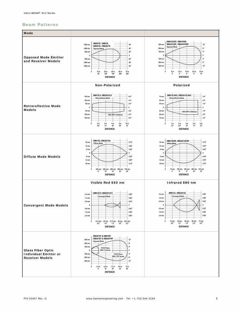
Beam Patterns
Mode
Opposed Mode Emitterand Receiver Models
75 m250'
60 m200'
45 m150'
30 m100'
15 m50'
0
0
500 mm
1000 mm
1500 mm
500 mm
1000 mm
1500 mm
0
20"
40"
60"
20"
40"
60"
DISTANCE
SMA91E / SM91R,SMA91E / SM2A91ROpposed Mode
3.0 m10'
2.4 m8'
1.8 m6'
1.2 m4'
.6 m2'
0
0
100 mm
200 mm
300 mm
100 mm
200 mm
300 mm
0
4"
8"
12"
4"
8"
12"
DISTANCE
SMA91ESR / SM91RSR,SMA91ESR / SM2A91RSROpposed Mode
Retroreflective ModeModels
Non-Polarized
10 m33'
8 m26'
6 m20'
4 m13'
2 m6.6'
0
0
50 mm
100 mm
150 mm
50 mm
100 mm
150 mm
0
2.0"
4.0"
6.0"
2.0"
4.0"
6.0"
DISTANCE
SM912LV, SM2A912LVRetroreflective Mode
With BRT-3 Reflector
Polarized
5 m16'
4 m13'
3 m10'
2 m6.6'
1 m3.3'
0
0
25 mm
50 mm
75 mm
25 mm
50 mm
75 mm
0
1.0"
2.0"
3.0"
1.0"
2.0"
3.0"
DISTANCE
SM912LVAG, SM2A912LVAGRetroreflective Mode
With BRT-3 Reflector
Diffuse Mode Models
750 mm30"
600 mm24"
450 mm18"
300 mm12"
150 mm6"
0
0
6 mm
12 mm
18 mm
6 mm
12 mm
18 mm
0
0.25"
0.50"
0.75"
0.25"
0.50"
0.75"
DISTANCE
SM912D, SM2A912DDiffuse Mode
375 mm15"
300 mm12"
225 mm9"
150 mm6"
75 mm3"
0
0
6 mm
12 mm
18 mm
6 mm
12 mm
18 mm
0
0.25"
0.50"
0.75"
0.25"
0.50"
0.75"
DISTANCE
SM912DSR, SM2A912DSRDiffuse Mode
Convergent Mode Models
Visible Red 650 nm
62.5 mm2.5"
50 mm2.0"
37.5 mm1.5"
25 mm1.0"
12.5 mm0.5"
0
0
0.8 mm
1.6 mm
2.4 mm
0.8 mm
1.6 mm
2.4 mm
0
0.03"
0.06"
0.09"
0.03"
0.06"
0.09"
DISTANCE
SM912CV, SM2A912CVConvergent Mode
Infrared 880 nm
75 mm3.0"
60 mm2.4"
45 mm1.8"
30 mm1.2"
15 mm0.6"
0
0
0.8 mm
1.6 mm
2.4 mm
0.8 mm
1.6 mm
2.4 mm
0
0.03"
0.06"
0.09"
0.03"
0.06"
0.09"
DISTANCE
SM912C, SM2A912CConvergent Mode
Glass Fiber OpticIndividual Emitter orReceiver Models
12 m40'
9.6 m32'
7.2 m24'
4.8 m16'
2.4 m8'
0
0
100 mm
200 mm
300 mm
100 mm
200 mm
300 mm
0
4"
8"
12"
4"
8"
12"
DISTANCE
SMA91EF & SM91RF,SMA91EF & SM2A91RFOpposed Mode
IT23S FibersWith L9 lenses
IT23S FibersWith L16F lenses
VALU-BEAM® 912 Series
P/N 03467 Rev. G www.bannerengineering.com - Tel: +1-763-544-3164 9
Mode
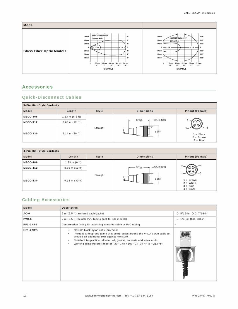
Glass Fiber Optic Models
500 mm20"
400 mm16"
300 mm12"
200 mm8"
100 mm4"
0
0
25 mm
50 mm
75 mm
25 mm
50 mm
75 mm
0
1"
2"
3"
1"
2"
3"
DISTANCE
SM912F/SM2A912FOpposed Mode
IT13S IT23S
37.5 mm1.5"
30 mm1.2"
22.5 mm0.9"
15 mm0.6"
7.5 mm0.3"
0
0
0.7 mm
1.3 mm
1.9 mm
0.7 mm
1.3 mm
1.9 mm
0
0.03"
0.05"
0.08"
0.03"
0.05"
0.08"
DISTANCE
SM912F/SM2A912FDiffuse Mode
BT23SBT13S
Accessories
Quick-Disconnect Cables
3-Pin Mini-Style Cordsets
Model Length Style Dimensions Pinout (Female)
MBCC-306 1.83 m (6.5 ft)
Straight
7/8-16UN-2B
ø 25.5
52 Typ.
23
1
1 = Black2 = Brown3 = Blue
MBCC-312 3.66 m (12 ft)
MBCC-330 9.14 m (30 ft)
4-Pin Mini-Style Cordsets
Model Length Style Dimensions Pinout (Female)
MBCC-406 1.83 m (6 ft)
Straight
7/8-16UN-2B
ø 25.5
52 Typ. 4
31
2
1 = Brown2 = White3 = Blue4 = Black
MBCC-412 3.66 m (12 ft)
MBCC-430 9.14 m (30 ft)
Cabling Accessories
Model Description
AC-6 2 m (6.5 ft) armored cable jacket I.D. 5/16-in; O.D. 7/16-in
PVC-6 2 m (6.5 ft) flexible PVC tubing (not for QD models) I.D. 1/4-in; O.D. 3/8-in
RF1-2NPS Compression fitting for attaching armored cable or PVC tubing –
HF1-2NPS • Flexible black nylon cable protector• Includes a neoprene gland that compresses around the VALU-BEAM cable to
provide an additional seal against moisture• Resistant to gasoline, alcohol, oil, grease, solvents and weak acids• Working temperature range of –30 °C to +100 °C (–34 °F to +212 °F)
VALU-BEAM® 912 Series
10 www.bannerengineering.com - Tel: +1-763-544-3164 P/N 03467 Rev. G

Extension Cables (without connectors)The following cables are available for extending the length of existing sensor cable. These are 30 m (100 ft) lengths ofVALU-BEAM cable. This cable may be spliced to existing cable. Connectors, if used, must be customer-supplied.
Model Type Used With:
EC312-100 4-conductor SM912 Series dc sensors
EC312A-100 2-conductor For all emitters and SM2A912 Series ac sensors
Retroreflective Targets
Banner offers a wide selection of high-quality retroreflective targets. See http://www.bannerengineering.com for complete information.
NOTE: Polarized sensors require corner cube typeretroreflective targets. Non-polarized sensors may useany retroreflective target.
Replacement Lens AssembliesVALU-BEAM lens assemblies are field-replaceable. In addition, some lenses may be used to convert from one sensingmode to another, or to change the sensing range of a particular sensor. The possible conversions are listed in the tablebelow.
Models Description Possible Sensing Mode or Range Changes
UC-900AG Replacement lens for LVAG Change LV to LVAG
UC-900C Replacement lens for C and CV Change LV to CV
UC-900DSR Replacement lens for DSR, ESR, and RSR Change D or F to DSR, EF to ESR, and RF to RSR
UC-900F Replacement lens for F Change D to F and DSR to F
UC-900FP Replacement lens for FP –
UC-900L Replacement lens for E, R, LV, and D Change LVAG to LV, CV to LV, DSR to D, and F to D
UC-900J Attach to E, R, ESR, RSR, LV, and D models Flat polycarbonate dust cover
Mounting Brackets
SMB30C• 30 mm split clamp, black
PBT bracket• Stainless steel mounting
hardware included• Mounting hole for 30 mm
sensor
66
56
13
A
B
Hole center spacing: A=ø 45Hole size: B=ø 27.2
SMB30SC• Swivel bracket with 30 mm
mounting hole for sensor• Black reinforced
thermoplastic polyester• Stainless steel mounting and
swivel locking hardwareincluded
67
58
29
B
A
Hole center spacing: A=ø 50.8Hole size: A=ø 7.0, B=ø 30.0
VALU-BEAM® 912 Series
P/N 03467 Rev. G www.bannerengineering.com - Tel: +1-763-544-3164 11
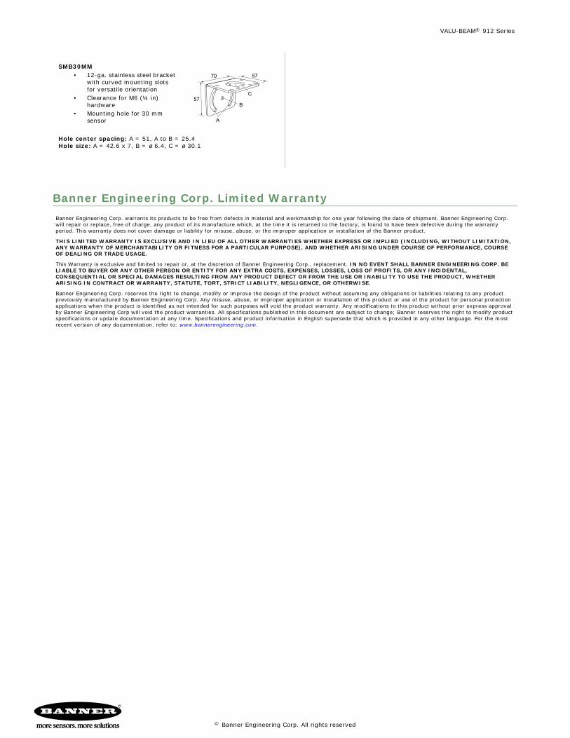
SMB30MM• 12-ga. stainless steel bracket
with curved mounting slotsfor versatile orientation
• Clearance for M6 (¼ in)hardware
• Mounting hole for 30 mmsensor
70
57
A
B
C
57
Hole center spacing: A = 51, A to B = 25.4Hole size: A = 42.6 x 7, B = ø 6.4, C = ø 30.1
Banner Engineering Corp. Limited WarrantyBanner Engineering Corp. warrants its products to be free from defects in material and workmanship for one year following the date of shipment. Banner Engineering Corp.will repair or replace, free of charge, any product of its manufacture which, at the time it is returned to the factory, is found to have been defective during the warrantyperiod. This warranty does not cover damage or liability for misuse, abuse, or the improper application or installation of the Banner product.
THIS LIMITED WARRANTY IS EXCLUSIVE AND IN LIEU OF ALL OTHER WARRANTIES WHETHER EXPRESS OR IMPLIED (INCLUDING, WITHOUT LIMITATION,ANY WARRANTY OF MERCHANTABILITY OR FITNESS FOR A PARTICULAR PURPOSE), AND WHETHER ARISING UNDER COURSE OF PERFORMANCE, COURSEOF DEALING OR TRADE USAGE.
This Warranty is exclusive and limited to repair or, at the discretion of Banner Engineering Corp., replacement. IN NO EVENT SHALL BANNER ENGINEERING CORP. BELIABLE TO BUYER OR ANY OTHER PERSON OR ENTITY FOR ANY EXTRA COSTS, EXPENSES, LOSSES, LOSS OF PROFITS, OR ANY INCIDENTAL,CONSEQUENTIAL OR SPECIAL DAMAGES RESULTING FROM ANY PRODUCT DEFECT OR FROM THE USE OR INABILITY TO USE THE PRODUCT, WHETHERARISING IN CONTRACT OR WARRANTY, STATUTE, TORT, STRICT LIABILITY, NEGLIGENCE, OR OTHERWISE.
Banner Engineering Corp. reserves the right to change, modify or improve the design of the product without assuming any obligations or liabilities relating to any productpreviously manufactured by Banner Engineering Corp. Any misuse, abuse, or improper application or installation of this product or use of the product for personal protectionapplications when the product is identified as not intended for such purposes will void the product warranty. Any modifications to this product without prior express approvalby Banner Engineering Corp will void the product warranties. All specifications published in this document are subject to change; Banner reserves the right to modify productspecifications or update documentation at any time. Specifications and product information in English supersede that which is provided in any other language. For the mostrecent version of any documentation, refer to: www.bannerengineering.com.
VALU-BEAM® 912 Series
© Banner Engineering Corp. All rights reserved