Validity from January 1-st, 2014 - sanitassk.eu
31
Validity from January 1-st, 2014
Transcript of Validity from January 1-st, 2014 - sanitassk.eu

Validity from January 1-st, 2014

wwwwww..ssaanniittaasssskk..eeuu 11 iinnffoo@@ssaanniittaasssskk..eeuu
TABLE OF CONTENTS page chapter
2 I. USING THE SANITAS PP-R SYSTEM
2 II. WARRANTY
2-5 2 3
3-4 4 5
III. BASIC INFORMATION ABOUT THE PRODUCT RANGE 1. PP-R pipe 2. Pipe STABI 3.SANITAS-GF 4.STABI OXY + 5. Fittings
6-7 IV. PROPERTIES OF THE SANITAS PP-R SYSTEM 5 1. Benefits 5 2. Products Labels and Packaging 6 3. Information about the Basic Material SANITAS PP-R 7 4. Manufacturing and Testing Standards 7 V. EXPECTED PROPERTIES 7 1. Basic Parameters of Distribution Pipes in Internal Water Piping 7 2. Basic Parameters of Heating Distribution Lines 7 VI. OPERATING PARAMETERS OF PIPES FROM PP-R – WATER PIPING
8-9 VII. OPERATING PARAMETERS OF PIPES FROM PP-R – HEATING 8 1. Heating System Concept 8 2. Determining Pipe Useful Life in a Heating System 9 3. Example of Determining Pipe Useful Life in a Heat Distribution System 9 4. Adjustments in a Heating System with Regard to Pipe Useful Life 9 5. Specific Features of Floor Heating
10 VIII. INSTALLATION OPTIONS
11 Tab.A Operating Parameters of PR-R Pipes for Water Piping 12 Tab.B Operating Parameters of PR-R Pipes for Heat Distribution System 13 Graf Toughness isothermal lines PP-R
14-15 IX. POLYFUSION WELDING PROCEDURE 14 1. Tool 14 2. Tool preparation 14 3. Material preparation
14-15 4. Own procedure at welding 15 5. Fusion welding procedure
16-24 X. ASSEMBLY REGULATION 18-21 1. Pipe linear expansion-dilatation-compensation
21 2. Horizontal pipeline SANITAS 22 3. Riser pipeline SANITAS 23 4. Connecting pipeline SANITAS PPR 24 5. Connecting pipeline SANITAS STABI
24-27 XI. GENERAL 24 1. Welding 24 2. Pipe cute 25 3. Threaded joints and passages plastic-metal 26 4. Insulation 26 5. Pressure Test 27 TEST PROTOCOL
28-29 XII. STORAGE CONDITIONS XIII. WASTE MANAGMENT – End of life

wwwwww..ssaanniittaasssskk..eeuu 22 iinnffoo@@ssaanniittaasssskk..eeuu
I. USING THE SANITAS PP-R SYSTEM
II. WARRANTY
A 10-year warranty is granted for products manufactured by SANITAS. This warranty is subject to correct
application of the products in compliance with the provisions of the Assembly Regulation below.
III. BASIC INFORMATION ABOUT THE PRODUCT RANGE
1. PP-R pipe
a) Use
It is a single-pipe polypropylene (PP-R Type 3) for the distribution of hot and cold water.
b) Basic information
Produced in sizes (indicated by the outer diameter of pipe) 20, 25, 32, 40, 50, 63 and 75 mm.
Pipes and adapting pieces of the SANITAS PP-R system are produced in the following dimensions (an external diameter of a pipe is specified) 20, 25, 32, 40, 50 and 63 mm. Depending on an estimated combination of pressure and temperature, the pipes are manufactured in various pressure series (with different wall thickness):
PN 10 (S5) – comprehensively for cold water and floor heating
PN 16 (S3,2) – comprehensively for hot water and cold water
PN 20 (S2,5) – comprehensively for hot water and central heating
The SANITAS PP-R piping systems can be used in indoor water distribution systems in residential houses, administrative buildings and in water distribution systems in industrial and agricultural applications. The SANITAS PPR system is designed to deliver cold and hot water and to deliver air and for floor heating. The SANITAS STABI PN 20 system can be used to deliver hot water and central heating (by this assembly regulation).

wwwwww..ssaanniittaasssskk..eeuu 33 iinnffoo@@ssaanniittaasssskk..eeuu
STABI PN 20 (S2,5) (3-sliding pipe PPR-Al-PPR) comprehensively for hot water and central heating
2. Pipes STABI
a) Use
The pipes STABI are three-layers: inner polypropylene pipe is at the high temperature (about 300
oC)
connected with aluminium foil and subsequently covered by outer layer of polypropylene (thickness of 0.5 – 0.8 mm). Thanks to the aluminium layer the pipe gets not only higher pressure and temperature resistance but also properties typical for metal pipes, e.g. higher toughness and lower thermal expansivity(3.5 - times lower than that of conventional expansion PP-R) and the oxygen barrier. For the reason of mechanical protection of the aluminium layer the pipe is covered by outer polypropylene layer. In sporadic cases it may come to precipitation of residual humidity from production of the inner polypropylene pipe in the form of small bubbles under this outer layer. With respect to the fact that this layer does not influence mechanical properties of the pipe, it concerns an aesthetic matter only. b) Basic information STABI Pipes are manufactured in the following sizes ø20, ø25, ø32, ø40, ø50, Ø63 mm, the pressure range PN 20 (SDR6). STABI supply pipes in gray with a description containing the manufacturer's name, pipe label, dimension x wall thickness, pressure board, date and time. They are packed in LDPE gray sleeves with a description. c) Characteristics of Pipe STABI With aluminum foil is 3.5 times lower linear thermal expansion, and higher rigidity than that of conventional PP-R pipes. Suitable for heating pipes, as well as the vertical risers. d) Distance of support tubes The maximum length of support is given in Table. Values are given for the temperature of the water is 80 ˚ C. For vertical lines, the distance is multiplied by 1.3.
Diameter pipe STABI (mm)
20
25
32
40
50
63
Distances of pipe supports (cm)
95 115 125 135 145 165
e) Operating parameters tubes STABI Operating parameters and the method of calculating life is the same as for plastic pipes PN20, with the difference that the recommended maximum heating temperature of heating water is 80 ˚ C. f) General Individual recommendations provided in the installation instructions SANITAS PP-R are also valid for tubes SANITAS STABI.

wwwwww..ssaanniittaasssskk..eeuu 44 iinnffoo@@ssaanniittaasssskk..eeuu
3. Pipe SANITAS-GF (Glass fiber) a) Use It is a three-layer pipes. Inner and outer layer are made of polypropylene type 3 (PP-R). Middle layer of polypropylene (PP-R) reinforced with glass fiber (GF). The composition of layers in a nutshell is PP-R/PP-R + GF / P-PR. Pipes SANITAS-GF are designed for distribution of hot and cold water, low temperature heating (up to 70 ˚ C), compressed air, and air conditioning. With the middle layer PP-R, which is reinforced with glass fiber pipe has SANITAS-GF higher stiffness and lower thermal expansion (3-times lower than conventional ovens PP-R pipes). SANITAS-GF has not oxygen barrier. b) Basic information Pipes SANITAS-GF are manufactured in the following sizes ø20, ø25, ø32, ø40 mm, the pressure range PN 20 (SDR6). Pipes SANITAS GF-supply in gray with a green stripe along the length of pipe containing the name and description of the manufacturer, marking pipe dimension x wall thickness, compression board, date and time. They are packed in LDPE green sleeves with a description. c) Characteristics of Pipe SANITAS-GF With the middle layer PP-R glass fiber is 3 times lower thermal expansion and higher stiffness than with conventional PP-R pipes. Suitable for low temperature heating pipes to 70 ˚ C, compressed air, and air conditioning. d) Distance of support tubes SANITAS-GF The maximum length of support is given in Table. Values are given for the temperature of the water is 80 ˚ C. For vertical lines, the distance is multiplied by 1.3.
Diameter pipe SANITAS-GF (mm)
20
25
32
40
50
63
Distances of pipe supports (cm)
90 110 120 130 140 160
e) Operating parameters tubes SANITAS-GF Operating parameters and the method of calculating life is the same as for plastic pipes PN 20 with the fact that the recommended maximum heating temperature of heating water to 70 ˚ C. f) General Individual recommendations provided in the installation instructions SANITAS PP-R are also valid for tubes SANITAS-GF. Increased attention should be paid to the protection of pipes against external shocks, especially at low temperatures. Pipes SANITAS-GF are compared with conventional PP-R pipes fragile especially at temperatures below +5 ˚ C. Pipes should be stored at a temperature of at least +5 ˚ C.
4. STABI OXY +
Pipe with new type of polypropylene intended for hot water and for heating up to 90°C with 100% oxygen barrier. Advantages:
higher pressure resistance at high tempreratures with using new material PP-R 4 ( PP-RCT)
bigger flow profile

wwwwww..ssaanniittaasssskk..eeuu 55 iinnffoo@@ssaanniittaasssskk..eeuu
3x lower length expansion than PPR pipes
service life minimum 50 years
5. The adapting pieces (fittings) The adapting pieces are produced for the highest PN 20 pressure series in various designs:
- Whole-plastic adapting pieces (elbows, T-pieces, sockets, pipe reducers, blind flanges),
- Adapting pieces combined with a brass nickel-coated thread for threaded joints (wall pieces, DG reducing sleeves, wall sets, T-pieces with a brass thread, screw couplings)
- Plastic valves with a brass top (standard and under plaster ones), - Plastic ball cocks with a brass nickel-coated ball, - Special elements (transfer bends, compensation piece a U-compensator). - Complements (welder, snips, adapter for welder, sealing compound for threaded
joints, stabi pipes shaver).

wwwwww..ssaanniittaasssskk..eeuu 66 iinnffoo@@ssaanniittaasssskk..eeuu
IV. PROPERTIES OF THE SANITAS PP-R SYSTEM 1. Benefits - the useful life of 50 years with proper application, - sanitary fitness, - no corrosion and no scaling, - flexible to bend; low mass; easy, quick and clean assembly - low noise levels, low pressure losses due to friction - high chemical resistance, recycling possible
2. Products Labels and Packaging Pipes and adapting pieces are labelled in the production process to facilitate their identification in a commercial network and in use.
The products are labelled at least as follows: Pipes: SANITAS, material, dimension, pressure series, production standard, date and time of production, PN 20 pipes are marked additionally with a continuous red line and PN 16 pipes are marked with a continuous blue line Adapting pieces: SANITAS, material, dimension and pressure series Pipes are packed in PE sleeves according to pressure series. The PN 20 pressure series is packed in red sleeves, the PN 16 pressure series is packed in blue sleeves and the PN 10 pressure series is packed in transparent sleeves Adapting pieces are packed in transparent PE bags and then in paper boxes. Every package of products is marked with a package label showing the name of the product, dimension of the product, pressure series, material, number of pieces, packaging date and ID of the person packing the
product. The possibility to identify every product is an important tool of quality assurance. In compliance with requirements of the DIN 8077 standard applicable for pipe production, the PN pressure series labels will be progressively replaced by S identification as follows: PN 10 = S 5 PN 16 = S 3,2 PN 20 = S 2,5
3. Information about the Basic Material Used in Production of SANITAS PP-R Systems
Pipes and adapting pieces produced by SANITAS are made from polypropylene type 3. Polypropylene type 3 = (statistical) polypropylene random copolymer (PP-R) Polypropylene is a polyolefin FirmSANITAS used polypropylene BOREALIS RA-130E from Finland s firm B R A IS
SELECTED CHARACTERISTICS OF PP-R
PROPERTIES TEST
CONDITIONS UNIT PPR VALUE
Specific weight g/cm3 0.9
Yield point in tension Mpa 25-26
Elongation at yield point % 10-15
E modulus of elasticity in bending N/mm2 850-900
Notch impact toughness 23
oC kJ/m
2 22+-3
0oC kJ/m
2 4-4.5
Temperature length dilatation factor
mm/moC 0.12
Heat conductivity factor w/moC 0.24

wwwwww..ssaanniittaasssskk..eeuu 77 iinnffoo@@ssaanniittaasssskk..eeuu
4. Manufacturing and Testing Standards Pipes and adapting pieces are manufactured in accordance with F-120/IS /TÚ Technical Conditions and in compliance with requirements of EN ISO15 874 and German standards DIN 8077, DIN 8078, DIN 16 962, DIN 4726 and ISO 3212 and ISO 7279 international standards. In order to assure quality of production in accordance with EN ISO 9001, the following aspects are checked on a regular basis and according to precisely specified procedures: - characteristics and parameters of the incoming raw material - parameters of products at specific production stages - equipment and tools used in production - parameters of measuring gauges
V. EXPECTED PROPERTIES 1. Basic Parameters of Distribution pipes in Internal Water Piping
The table below shows basic general criteria to be considered when choosing a pressure series, i.e. pressure
and temperature values fund in indoor water piping:
Medium Max. working pressure
(bar) Max. working
temperature (°C) Cold water 0-10 up to 20 °C
Hot water 0-10 up to 60 °C
For drinking water, the maximum temperature is 20 °C due to sanitary reasons. The maximum temperature in hot water distribution pipes at the place of discharge fixture is estimated to be 57 °C as a protection against scalding. For hot water distribution pipes, a short-term pre-heating to higher temperatures (70 °C) is planned at the heating point due to sanitary reasons to eliminate pathogenic mycobacteria and legionella bacteria. The SANITAS PP-R piping system can be used in any tubing of indoor water piping (cold drinking water, hot domestic water and circulation. The useful life of 50 years is expected for a plastic piping system provided that the material and pressure series have been selected properly and the system has been applied correctly. The pressure series is selected by a designer according to the water heating system and temperature control.
2. Basic Parameters of Heating Distribution Lines To assess suitability of using SANITAS PP-R system products in heating, it is necessary to use the value of the input calculated value of heated water t1, indicating the highest temperature found in the system. A designer will select the heating system depending on the required temperature at input into heating bodies, according to technical capacities of the heat source and type of the expansion vessel. The following heating systems are distinguished based on this value:
The SANITAS PP-R piping system can be used especially for warm-water systems with a temperature gradient of 75/65°C, 70/50°C, 70/60°C and for low-temperature systems of 55/45°C, 45/35°C a 35/25°C.
VI. OPERATING PARAMETERS OF PIPES FROM PP-R – WATER PIPING Operating parameters refer to the maximum working pressure, temperature and useful life and correlations between them. Operating parameters are shown in Table 1 on page 11, identifying also pressure series of pipes for distribution of cold and warm water. The safety coefficient of 1.5 was used to make the calculation.
Heating system Temperature range
Usage of the SANITAS PP-R system
Warm water (low temperature ) t1 65°C suitable (useful life 50 years)
Warm water 65°C < t1 80°C suitable (useful life 25 years)

wwwwww..ssaanniittaasssskk..eeuu 88 iinnffoo@@ssaanniittaasssskk..eeuu
In general, the higher the pressure series number, the higher operating pressures are allowed at the identical temperature and the maximum operating pressure of water in a given pressure series decreases with the increasing temperature. The PN 16 pressure series can be used in hot domestic water distribution pipes equipped with a good-quality control technology for water heating secured by the adequate maximum temperature of the hot domestic
water. VII. OPERATING PARAMETERS OF PIPES FROM PP-R – HEATING 1. Heating System Concept
SANITAS PP-R PN 20 pipes and SANITAS STABI pipes are intended for central heating purposes. The principle of calculating the heating system is identical as for standard metallic pipes. Comparing metallic and plastic pipes, the principal difference in terms of designing is that plastic tubes should not be placed freely, with the exception of technical floors and similar installation areas. Taking this into account when pipe runs are planned will ensure an economical and safe design. The quality of the whole system can be improved when different properties of plastics are considered. A typical example of an adequate placement of plastic pipes is the so-called star system. Basically, this involves a double-pipe vertical heating system with a limited number of lifting tubes and very long heating body extension tubes running in a concrete layer of the floor. This system is constructed specifically for plastic distribution lines, preferring the minimum number of joints on the plastic piping to the
minimum pipe length. For this purpose, it is optimum to use SANITAS PP-R pipes wound in reels. Another suitable alternative for plastic pipes is: a standard horizontal system in which pipes run in a trough or around the building structure is a cover ensuring mechanical protection of the pipe, or which will allow dilatations and improves aesthetic impression of the distribution pipes. A designed pipeline should be evaluated in terms of its useful life. To make such evaluation, it is necessary to know: Maximum water temperature (°C) Maximum operating pressure (MPa) External diameter of the pipe used (mm) Thickness of the wall of the pipe used (mm) Safety coefficient for heating Duration of the heating period in a year (in months)
2. Determining Pipe Lifecycle in a Heating System To determine useful life, it is necessary to determine rated tension in the pipe wall derived from the maximum operating pressure from this formula: Conversion: 1 Mpa = 10 bar
When the rated tension is determined from the formula above, put this value on the chart on page 13. Tension values are shown on the vertical axis. Determine the point of intersection of the rated tension value (horizontal line) with the isothermal line of the maximum water temperature (inclined line). Draw a perpendicular line from the point of intersection to the horizontal axis, which shows time in hours or in years (smaller scale). Read the expected minimum useful life of the pipe with continuous heating from the horizontal line. Calculate the quotient of the calendar year duration (in months) and the heating period duration (in months) and multiply the determined minimum useful life of the pipe with this quotient provided, of course, that any other assembly and
Symbol Quantity σv D s p k
Rated tension (MPa) External pipe diameter (mm) Wall thickness (mm) Maximum pressure (MPa) Safety coefficient(2.5 for heating)

wwwwww..ssaanniittaasssskk..eeuu 99 iinnffoo@@ssaanniittaasssskk..eeuu
operating conditions have been satisfied and the calculation prerequisites (max. operating pressure and temperature) have been met.
3. Example of Determining Pipe Lifecycle in a Heat Distribution System
Input data:
The minimum useful life with continuous heating (derived from the chart on page 13 for the isothermal line of 80 °C) is 216,000 hours, i.e. 25 years. Considering the duration of the heating period, the resultant expected useful life is:
4. Adjustments in a Heating System with Regard to Pipe Useful Life If the result obtained from the evaluation is not satisfactory, you can make the following adjustments:
reduce the maximum operating pressure – it is necessary to make a new calculation of the heating system and a new useful life assessment,
reduce the maximum operating temperature of the heated water – it is necessary to make a new calculation of the heated system and a new useful life assessment. The useful life will be significantly extended.
5. Specific Features of Floor Heating
When installing floor heating, maximum surface temperatures of the floor finish layer in rooms must be respected. Low speeds of heated water flows (approximately 0.3 m/s) are chosen for floor heating to allow transfer of heat. Pressure in the pipes is determined according to operating parameters of the heating system. The temperature of the heated water is determined by a calculation depending in particular on a type of the room, composition of the floor structure and the external rated temperature at the place of the building.
In general, maximum temperatures of 45 °C and pressures of 0.3 MPa are used in floor heating. SANITAS PP-R PN 10 pipes are used for these parameters. Pipes wound in reels are used to lay heating circuits. Pipes in reels are more beneficial because no joints need to be used. Heating pipes are laid in the floor structure in spirals. SANITAS manufactures floor heating pipes in ø20 mm diameters and PN 10 pressure series. Pipes wound in reels are 100 and 200 m long. A floor heating project should specify how the heating output of the floor will be controlled and how the
maximum surface temperature will be observed.
Parameter Value Pipes used PN 20 (20x3,4mm)
Maximum operating water temperature
80°C
Maximum operating pressure 0,22 MPa
Duration of the heating period
7 mesiacov
Safety coefficient 2,5
σv = 4,3.2
)4,320.(22,0 .2,5=1,34 Mpa
25 rokov . mes
mes
7
12= 43 rokov
Room type Maximum surface temperature of the floor (°C)
Living room 26
Bathroom 30
Area around a pool 32
wwwwww..ssaanniittaasssskk..eeuu 1100 iinnffoo@@ssaanniittaasssskk..eeuu
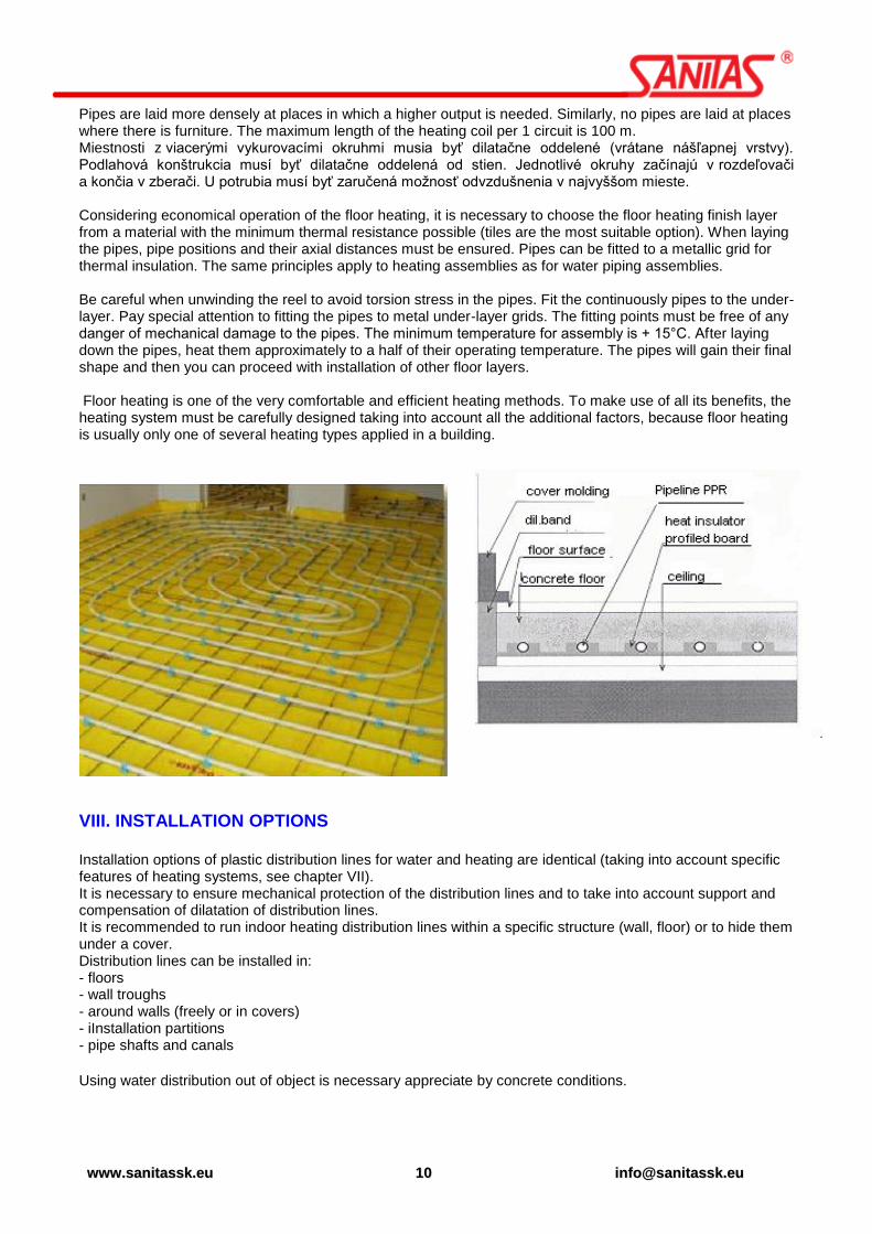
Pipes are laid more densely at places in which a higher output is needed. Similarly, no pipes are laid at places where there is furniture. The maximum length of the heating coil per 1 circuit is 100 m. Miestnosti z viacerými vykurovacími okruhmi musia byť dilatačne oddelené (vrátane nášľapnej vrstvy). Podlahová konštrukcia musí byť dilatačne oddelená od stien. Jednotlivé okruhy začínajú v rozdeľovači a končia v zberači. U potrubia musí byť zaručená možnosť odvzdušnenia v najvyššom mieste. Considering economical operation of the floor heating, it is necessary to choose the floor heating finish layer from a material with the minimum thermal resistance possible (tiles are the most suitable option). When laying the pipes, pipe positions and their axial distances must be ensured. Pipes can be fitted to a metallic grid for thermal insulation. The same principles apply to heating assemblies as for water piping assemblies. Be careful when unwinding the reel to avoid torsion stress in the pipes. Fit the continuously pipes to the under-layer. Pay special attention to fitting the pipes to metal under-layer grids. The fitting points must be free of any danger of mechanical damage to the pipes. The minimum temperature for assembly is + 15°C. After laying down the pipes, heat them approximately to a half of their operating temperature. The pipes will gain their final shape and then you can proceed with installation of other floor layers. Floor heating is one of the very comfortable and efficient heating methods. To make use of all its benefits, the heating system must be carefully designed taking into account all the additional factors, because floor heating is usually only one of several heating types applied in a building.
VIII. INSTALLATION OPTIONS Installation options of plastic distribution lines for water and heating are identical (taking into account specific features of heating systems, see chapter VII). It is necessary to ensure mechanical protection of the distribution lines and to take into account support and compensation of dilatation of distribution lines. It is recommended to run indoor heating distribution lines within a specific structure (wall, floor) or to hide them under a cover. Distribution lines can be installed in: - floors - wall troughs - around walls (freely or in covers) - iInstallation partitions - pipe shafts and canals
Using water distribution out of object is necessary appreciate by concrete conditions.

wwwwww..ssaanniittaasssskk..eeuu 1111 iinnffoo@@ssaanniittaasssskk..eeuu
Tab. A Operating Parameters of PR-R Pipes for Water Piping (according to DIN 8077/1997)
TEMPERATURA (oC)
USEFUL LIFE
[YEARS]
PRESSURE SERIES
PN 10 PN 16 PN 20 STABI,GF
PERMISSIBLE OPERATING OVER-PRESSURE [BAR]
10
1 17,6 27,8 35 35
5 16,6 26,4 33,2 33,2
10 16,1 25,5 32,1 32,1
25 15,6 24,7 31,1 31,1
50 15,2 24 30,3 30,3
20
1 15 23,8 30 30
5 14,1 22,3 28,1 28,1
10 13,7 21,7 27,3 27,3
25 13,3 21,1 26,5 26,5
50 12,9 20,4 25,7 25,7
30
1 12,8 20,2 25,5 25,5
Safe
ty c
oeffic
ien
t 1.5
5 12 19 23,9 23,9
10 11,6 18,3 23,1 23,1
25 11,2 17,7 22,3 22,3
50 10,9 17,3 21,8 21,8
40
1 10,8 17,1 21,5 21,5
5 10,1 16 20,2 20,2
10 9,8 15,6 19,6 19,6
25 9,4 15 18,8 18,8
50 9,2 14,5 18,3 18,3
50
1 9,2 14,5 18,3 18,3
5 8,5 13,5 17 17
10 8,2 13,1 16,5 16,5
25 8 12,6 15,9 15,9
50 7,7 12,2 15,4 15,4
60
1 7,7 12,2 15,4 15,4
5 7,2 11,4 14,3 14,3
10 6,9 11 13,8 13,8
25 6,7 10,5 13,3 13,3
50 6,4 10,1 12,7 12,7
70
1 6,5 10,3 13 13
5 6 9,5 11,9 11,9
10 5,9 9,3 11,7 11,7
25 5,1 8 10,1 10,1
50 4,3 6,7 8,5 8,5
80
1 5,5 8,6 10,9 10,9
5 4,8 7,6 9,6 9,6
10 4 6,3 8 8
25 3,2 5,1 6,4 6,4
95 1 3,9 6,1 7,7 7,7
5 2,5 4 5 5
COLD WATER HOT WATER

wwwwww..ssaanniittaasssskk..eeuu 1122 iinnffoo@@ssaanniittaasssskk..eeuu
Tab.B Operating parameters potrubia of PR-R Pipes for heating (by DIN 8077/1997)
The operating time specified in the table is counted for continuous operation. The resulting lifetime is to be finish counted according to the example for lifetime determination on the page 6.
TEMPERATURE (oC)
USEFUL LIFE
[YEARS]
PRESSURE SERIES
PN 10 PN 16 PN 20 STABI, GF
PERMISSIBLE OPERATING OVER-PRESSURE [BAR]
30
1 7,68 12,12 15,30 15,30
Safe
ty c
oeffic
ien
t 2,5
5 7,20 11,40 14,34 14,34
10 6,96 10,98 13,86 13,86
25 6,72 10,62 13,38 13,38
50 6,54 10,38 13,08 13,08
40
1 6,48 10,26 12,90 12,90
5 6,06 9,60 12,12 12,12
10 5,88 9,36 11,76 11,76
25 5,64 9,00 11,28 11,28
50 5,52 8,70 10,98 10,98
50
1 5,52 8,70 10,98 10,98
5 5,10 8,10 10,20 10,20
10 4,92 7,86 9,90 9,90
25 4,80 7,56 9,54 9,54
50 4,62 7,32 9,24 9,24
60
1 9,24 9,24
5 8,54 8,54
10 8,28 8,28
25 7,98 7,98
50 7,62 7,62
70
1 7,80 7,80
5 7,14 7,14
10 7,02 7,02
25 6,06 6,06
50 5,10 5,10
80
1 6,54 6,54
5 5,76 5,76
10 4,80 4,80
25 3,84 3,84
95 1 4,62 4,62
5 3,00 3,00
FLOOR HEATING OTHER HEATING

wwwwww..ssaanniittaasssskk..eeuu 1133 iinnffoo@@ssaanniittaasssskk..eeuu
Tougness isothermal lines PP-R
Rate
d t
en
sio
nσ
v [
Mp
a]
Useful life [hours]

wwwwww..ssaanniittaasssskk..eeuu 1144 iinnffoo@@ssaanniittaasssskk..eeuu
IX. FUSION WELDING PROCEDURE 1. Tools
a) electric welding machine for fusion welding
b) welding attachments on the welding machine
c) contact thermometer
d) special shears or cutter for plastic pipes
e) sharp knife
f) degreasing agent + piece of cloth of non-synthetic material
g) meter and marker
h) at welding of diameters over 50 mm assembly fixture for welding
i) trimmer for STABI pipes at welding of pipes SANITAS STABI
2. Tool preparation
Fasten the heating attachments onto the welding machine. Set welding machine to 250°C - 270°C using a regulator and connect it to the electric network. The time of heating and full warming-up of the welding machine is signalized by light emitting diodes (see the Manual for welding machine operation). Check the temperature correctness by means of a contact thermometer and finish regulation to 260
°C. In warmed
condition clean up the warming-up attachments from the previous welding by a non-synthetic piece of cloth so as to avoid damage to the Teflon coating. Correctness of the special shears or trimmer functioning check by a test pipe cutting-off. During shearing it should not come to squeezing the outer diameter of the pipe. If this occurs it is required to sharp the shears or the trimmer.
3. Material preparation Check carefully the entire material. In single elements, in no case the wall may be weakened, check also their functions (check the threads using a counterpart). Clean and degrease the fittings and pipe parts which you are going to weld. Push the fittings on the welding attachment in order to check if they are loosened. Discard the fittings that are moving on the welding attachment!!!
4. Own procedure at welding
a) Measure the required length of the pipe and cut the pipe. Clean and degrease the pipe edges. With the pipe diameters over 40 mm it is recommended to bevel the angle of 30
o – 40
o on the outer edge of
the pipe using a special fixture (deburring). This prevent from the material folding during inserting the pipe end into the fitting.
b) If you are welding the pipes SANITAS STABI, remove the top plastic and the middle aluminium coating in the length of insertion into the fitting neck. You work with such treated pipe in the same manner like with standard all-plastic pipe SANITAS PP-R.
Pipe cutting
STABI pipe slipping

wwwwww..ssaanniittaasssskk..eeuu 1155 iinnffoo@@ssaanniittaasssskk..eeuu
c) It is recommended to mark on the pipe by marker (felt pen) the length of insertion of the pipe end into the fitting according to the welding length of the respective fitting. It is required to take into account that the pipe end cannot be pressed up to the position stop of the fitting welding depth. There must be a free space of min. 1 mm for the folding material which would cause reducing the flow in the fitting at the place of weld. With the pipes STABI the insertion length into the fitting is set on the trimmer.
d) It is recommended to mark the weld position on both the pipe and the fitting which can prevent from the pipe moving round towards the fitting after inserting. For this purpose the assembly match marks on the fittings can be used. After marking the spots to be welded should be cleaned and degreased. Without degreasing it can come to bad quality interconnection of melted layers.
5. Fusion welding procedure
First, put the fitting, which has a thicker wall than the pipe and its warming-up takes more time, onto the warmed up attachment. Check if the fitting is not too loose on the attachment. The fitting which does not fit tightly on the whole surface of the attachment should be discarded because non-uniform heating leads to bad quality weld. After the fitting, insert the pipe in the warming-up fitting. The same is valid for tightness of insertion as in the case of the fitting. Warm up both the parts for the time stated in the table of welding for PP-R. The time of warming-up is to be measured from the moment when both the pipe and fitting are put on the full length. At inserting the pipe and the fitting it is possible to move round slightly by both the parts (max. to 10°). During warming up no turning round is allowed in order to avoid the material folding.
Heat-up pipe and
fitting
Extraction pipe and fitting
Introduction pipe and
fitting
After the warming-up period is over, take out both the pipe and the fitting from the attachment and connect them in a way that the pipe is inserted using a slight pressure without moving round into the fitting up to the length of insertion. Check the axial connection of the pipe and the fitting. The table also shows maximum time of transfer (the time from pulling-out up to the inserting the fitting and the pipe). In the case of exceeding the time there is a risk of cooling down the melted layer and forming a cold joint of bad quality. The fresh joint is to be fixated for 20 – 30 seconds while it comes to a partial cooling down the joint. Such joint does not allow pushing the pipe out of the fitting or to a change of the fitting position towards the pipe.
The connecting pipeline filling up with water is possible to done 1 hour after making the weld.

wwwwww..ssaanniittaasssskk..eeuu 1166 iinnffoo@@ssaanniittaasssskk..eeuu
X. ASSEMBLY A project documentation based on applicable standards is a prerequisite of successful assembly of distribution pipes. Rules contained in this Assembly Regulation do not replace a project documentation in any way. Plastic Pipes are Joined by Polyfusion Welding as a Rule As a rule, DG-reducing sleeves with pressed brass nickel-coated casting and external/internal thread are used to join metal and plastic.
Threaded joints are sealed only by a sealant or a teflon tape or a teflon thread. We dissuade use hemp
from reason abnormal tension on more sealing material. Plastic water distribution pipes must be thermally insulated in accordance with provisions of STN 73 6660 – Indoor Water Pipes. It is recommended to insulate them by expanded polystyrene-based pull-on insulation with enclosed cell structure. Distribution pipes are fitted by creating fixed points (PB) at a certain span (for example, 4 m) and the pipe is fitted between these points by clips that allow a sliding motion of the pipe in thermal expansion. This is a sliding fitting (KU), see figure 1. A fixed point can be created as shown in figure 1.1 by running a branch through a wall or by installing sliding pipe clips from both sides of an adapting piece (socket, T-piece). A fixed point (PB) on a joint of two pipes can be also created using a special socket with a footing (product No. 85.2020 or other way.
Example of placing supports for a sliding layout
Sliding Fitting (KU) in a pipe clip in troughs
PP-R WELDING TABLE
Diameter (mm) Melt-down
length (mm) Heating time T1
(sec) Processing time
T2 (sec) Joining time T3
(sec) Cooling time T4
(min)
20 12 5 3
5 2
25 13 7 7
32 14,5 8
6
8
4 40 16 12 12
50 18 18 18
63 24 24 8 30 6

wwwwww..ssaanniittaasssskk..eeuu 1177 iinnffoo@@ssaanniittaasssskk..eeuu
Fixed point (PB) fitting between pipe clips branch pipeline
special fitting – fixed point Distances of pipe supports from PP-R in PN 10 are shown in table 3. For PN 16 pipes, these distances are multiplied by a coefficient of 1.1 and by a coefficient of 1.2 for PN 20 pipes.
diameter d (mm)
Fitting distance depending on operating temperature (cm)
20 oC 30
oC 40
oC 50
oC 60
oC 70
oC 80
oC
20 80 75 70 70 65 60 60
25 85 85 85 80 75 75 70
32 100 95 95 90 85 80 75
40 110 110 105 100 95 90 85
50 125 120 115 110 105 100 90
63 140 135 130 125 120 115 105
diameter d (mm)
Fitting distance depending on operating temperature (cm) pipes
SANITAS STABI
20 120
25 140
32 145
40 150
50 155
63 165

wwwwww..ssaanniittaasssskk..eeuu 1188 iinnffoo@@ssaanniittaasssskk..eeuu
1. Pipe Linear Expansion – dilatation – compensation
Temperature difference in assembly and operation of distribution pipes, when pipes deliver water of different temperature than the temperature used during the assembly, results in changes in length – expansion or reduction in any material. Overall reduction or expansion depends on the thermal expansion coefficient of the
material, pipe length and temperature difference t.
The expansion coefficient for PP-R = 0,12 mm/1 °C, , what means that when the temperature of the
medium is increased by 1 °C, a 1 m long pipe will expand by 0.12 mm. Pipe length L refers to a distance from
one fixed point to another or from one fixed point to a change in direction (e.g. an elbow).
Overall expansion (or reduction) is calculated from the following relationship:
l= expansion in mm
tcoefficien
L = pipe length between two fixed points in m
t = temperature difference °C
Example: A pipe 5 m long, temperature difference (60 C – 20 C) 40 C, coefficient = 0,12. Δl = 0,12·5·40= 24 mm
When the temperature is increased by 40°C, a 5 m long pipe will expand by 24 mm. This expansion must be compensated.
The l expansion can be derived directly from the table below or from the scheme below „
Expansion PP-R pipes“:
Expansion Δ l (mm)
PP-R Pipe length in m
1 2 3 4 5 6 7 8 9 10 15
Te
mp
era
ture
dif
fere
nc
e Δ
t
(oC
)
10 1,2 2,4 3,6 4,8 6 7,2 8,4 9,6 10,8 12 18
20 2,4 4,8 7,2 9,6 12 14,4 16,8 19,2 21,6 24 36
30 3,6 7,2 10,8 14,4 18 21,6 25,2 28,8 32,4 36 54
40 4,8 9,6 14,4 19,2 24 28,8 33,6 38,4 43,2 48 72
50 6 12 18 24 30 36 42 48 54 60 90
60 7,2 14,4 21,6 28,8 36 43,2 50,4 57,6 64,8 72 108
70 8,4 16,8 25,2 33,6 42 50,4 58,8 67,2 75,6 84 126
80 9,6 19,2 28,8 38,4 48 57,6 67,2 76,8 86,4 96 144
90 10,8 21,6 32,4 43,2 54 64,8 75,6 86,4 97,2 108 162
100 12 24 36 48 60 72 84 96 108 120 180

wwwwww..ssaanniittaasssskk..eeuu 1199 iinnffoo@@ssaanniittaasssskk..eeuu
Expansion Δ l (mm)
STABI Pipe length in m
1 2 3 4 5 6 7 8 9 10 15
Te
mp
era
ture
dif
fere
nc
e Δ
t (
oC
)
0 0 0 0 0 0 0 0 0 0 0 0
5 0,25 0,5 0,75 1 1,25 1,5 1,75 2 2,25 2,5 3,75
10 0,5 1 1,5 2 2,5 3 3,5 4 4,5 5 7,5
15 0,75 1,5 2,25 3 3,75 4,5 5,25 6 6,75 7,5 11,3
20 1 2 3 4 5 6 7 8 9 10 15
25 1,25 2,5 3,75 5 6,25 7,5 8,75 10 11,3 12,5 18,8
30 1,5 3 4,5 6 7,5 9 10,5 12 13,5 15 22,5
35 1,75 3,5 5,25 7 8,75 10,5 12,3 14 15,8 17,5 26,3
40 2 4 6 8 10 12 14 16 18 20 30
45 2,25 4,5 6,75 9 11,3 13,5 15,8 18 20,3 22,5 33,8
50 2,5 5 7,5 10 12,5 15 17,5 20 22,5 25 37,5
55 2,75 5,5 8,25 11 13,8 16,5 19,3 22 24,8 27,5 41,3
60 3 6 9 12 15 18 21 24 27 30 45
65 3,25 6,5 9,75 13 16,3 19,5 22,8 26 29,3 32,5 48,8
70 3,5 7 10,5 14 17,5 21 24,5 28 31,5 35 52,5
75 3,75 7,5 11,3 15 18,8 22,5 26,3 30 33,8 37,5 56,3
80 4 8 12 16 20 24 28 32 36 40 60
The expansion coefficient for PP-R SANITAS STABI 0,05 mm/1°C what means that when the temperature of the medium is increased by 1 °C, a 1 m long pipe will expand by 0,05 mm. Example: A pipe 5 m long, temperature difference (60 C – 20 C) 40 C, coefficient = 0,05. Δl = 0,05·5·40= 10 mm When the temperature is increased by 40°C, a 5 m long pipe will expand by 10 mm.

wwwwww..ssaanniittaasssskk..eeuu 2200 iinnffoo@@ssaanniittaasssskk..eeuu
If the changes in pipe length are not adequately compensated (if the pipe is not allowed to extend and shrink), additional tensile and compressive stress is accumulated in pipe walls and this can result in a significant reduction of its useful life. An adequate method of length compensation of external piping is the method in which pipes are bent in a direction perpendicular to the original piping and a free compensating length L1 is left on this perpendicular line. This will ensure that there will be no additional compressive or tensile stress developed in the pipe wall when the direct piping is dilated. This compensation method is shown in Fig.
If it is necessary to return the piping to its original direction, you can create a U-compensator at the same section as shown in Fig.
For example, there is a pipe of 6 m, 25 mm diameter and the temperature difference is 40 C. Then you
get expansion l and compensating length L1:
l = 6·40·0,12 = 28,80 mm The compensating length L1 (length of the branch arm or length of the U-compensator arm) is calculated as follows: L1 = arm length (mm) k = material constant for PPR = 30 (no dimension) D = high pipe diameter (mm)
l = rated expansion or reduction calculated from the formula above
L1 30·√25·28,8 805 mm
PB = fixed point
KU = sliding fitting
l = expansion
L = pipe length
L1 = arm length up to the first
fitting (compensating length)
L2 = sliding fitting (KU)distance
l = dilatation size
(expansion)

wwwwww..ssaanniittaasssskk..eeuu 2211 iinnffoo@@ssaanniittaasssskk..eeuu
2. Horizontal pipeline SANITAS laying In the case of horizontal pipelines it is required to take care of dilatation and to solve their compensation and method of laying the pipeline. The most frequently used are – galvanized troughs, sleeves or grooves that must be loose.
Pipe diameter in mm
distance between fixed points L(m)
PPR STABI
20 9 27
25 10 30
32 12 36
40 14 42 U-compensator SANITAS
Compensation piece
Table for installation of compensation
piece and U-compensator SANITAS

wwwwww..ssaanniittaasssskk..eeuu 2222 iinnffoo@@ssaanniittaasssskk..eeuu
Compensation of linear expansion is to be performed by a change in the line (pipeline height) or by U compensator. Compensation can be designed in vertical or parallel to the ceiling structure.
3. Riser pipeline SANITAS laying A B
On the ascending pipeline it should be put stress on layout of fixed points (PB), slide mountings (KU) and suitable compensations. Compensation on ascending pipelines is ensured by:
- Slide mounting on the ascending pipeline foot (pict. A)
- Compensation
loop (pict. B)
By changing the height of
the pipeline
U-compensator SANITAS

wwwwww..ssaanniittaasssskk..eeuu 2233 iinnffoo@@ssaanniittaasssskk..eeuu
If the ascending pipeline should be divided into more dilatation sections, it is done by layout of fixed points. The fixed point (PB) should be installed on the ascending pipeline under and over the T-piece, at a branch pipe or branch sleeve in the point of the pipeline connection, which simultaneously prevents from the pipeline falling. Between the fixed points then should be the pipeline dilatation enabled. At branching to the connecting pipeline it is required to take respect to the pipeline dilatation:
- by sufficient distance between the ascending pipeline and the wall passage (pict. a), - by possibility of the connecting pipeline movement in the place of passage through an
opening in the wall (pict. b), - by creation of compensation length for dilatation of the ascending pipeline at
perpendicular (pict. c).
4. Connecting pipeline SANITAS PPR laying
The connecting pipeline is to be mainly made of diameter ø 20 and ø 25 mm and it is led mostly in a groove. The groove for insulated pipeline must be loose and must enable the pipeline dilatation. Insulation on the pipeline is needed not only for thermal insulation but also for prevention from mechanical damage and also as a layer facilitating compensation of linear expansion. Before walling-up it is necessary to anchor the pipeline in the groove carefully (plastic, metal clips, fixing with plaster, etc.)
a b c

wwwwww..ssaanniittaasssskk..eeuu 2244 iinnffoo@@ssaanniittaasssskk..eeuu
5. Connecting pipeline SANITAS STABI laying
The pipeline SANITAS STABI has due to the inserted aluminium layer 3-times less expansivity, better stiffness and higher mechanical resistance than the standard pipeline PP-R. You can install the pipeline SANITAS STABI by the same, above described, procedure as an all-4plastic pipeline, it means in standard procedure for solving the compensations when the possibility of higher distance of supports will be utilized and compensation lengths will be markedly smaller. It is possible to use so-called rigid mounting at laying down in a groove. It means that fixed points are mounted on the pipeline in the way that thermal expansivity is transferred into the pipeline material and does not become evident. Pre-condition for this mounting are the sleeves which will be really able to bear the pipeline and will be sufficiently anchored. The connecting pipeline SANITAS STABI is suitable for laying down the pipe round a building structure to individual drain fittings, in this way higher rigidity of the pipeline is used. There is also suitable laying down the pipeline in the floor structure as the stability of size and higher mechanical resistance of the pipeline can be used.
XI. GENERAL
Only components not damaged or soiled during transportation and storage can be used for assembly.
The minimum temperature for assembling plastic distribution lines is +5 °C due to welding. It is difficult to create conditions needed to form good quality joints at lower temperatures.
The plastic system components must be protected against bumps, hits, falling materials and mechanical damage all the time during the assembly and transportation.
Pipes are bent without heating at the temperature of +15 °C in minimum. For pipes with diameter of 20 – 32 mm, the minimum bend radius is 8 times the pipe diameter (D).
Avoid contact of components with open flame.
Pipes are crossed using special components designed for this purpose.
Polyfusion parts are joined by polyfusion welding. A high-quality homogenous joint will be created by the welding. The procedure must be followed consistently and proper equipment should be used.
For threaded joints use threaded adapting pieces. It is forbidden to cut threads for plastic components. Seal the threads by a Teflon tape or a special sealant.
If a combined adapting piece is followed by a metal pipe, it should not be soldered or welded close to the adapting piece due to a possible transfer of heat to the adapting piece.
It is recommended to use plastic plugs to close wall elbows or a universal wall set before assembling discharge fittings (for example during a pressure test).
1. Welding
The fusion welding is to be performed with the fittings made of PPR, pipes of PPR all-plastic and of STABI. Fusion welding should be performed exactly according to the stated work procedure.
2. Pipe cutting
The pipes may be divided (cut and shear) only by sharp and properly sharpened tools. We recommend using a special shear or cutter for plastic pipeline.

wwwwww..ssaanniittaasssskk..eeuu 2255 iinnffoo@@ssaanniittaasssskk..eeuu
3. Threaded joints and passages plastic-metal For passage plastic-metal in pipelines there are on principle used adaptors with moulded brass nickel-coated female or male threads. For tightening the threaded joints with moulded brass threads and an octagon directly on the metal part there is a tightening wrench used!. For tightening the threaded joints with brass sprayed metal without brass hexagon or octagon there is used a tightening wrench with a tape.
For closing the wall-mounted elements and wall-mounted sets before drain fitting mounting (during pressure testing) there are plastic caps used.
Special snips
Plastic tube cutter
End plug for wall-mounted elbow

wwwwww..ssaanniittaasssskk..eeuu 2266 iinnffoo@@ssaanniittaasssskk..eeuu
4. Insulation A pipeline for warm water and central heating is to be insulated against heat loss; a pipeline for cold water is to be insulated against heat gains and against dew formation on the pipeline. Insulation of a pipeline with cold water for keeping the temperature of max. 20°C is important with respect to keeping hygienic compliance of drinking water. Identically, keeping of warm water temperature at upper limit which is stated by the standard with respect to scalding and to reduction of bacteria influence. It is required to insulate the pipeline throughout the entire line, including fittings and fixtures. It is necessary to ensure the designed minimum thickness of insulation over the entire perimeter of the pipeline and throughout the entire line. (It means that insulation which should be put on the pipeline cut must be after mounting jointed again into a compact profile, e.g. by bonding, clips or adhesive paste). In case of water transport it is necessary to be aware of that the plastic pipe has better thermal-insulating properties than a metal one. By installing a plastic pipeline it is possible to save operating costs! In the case of large consumption, for example in bathrooms, bath tubes, washing machines, etc. during flow of warm water in a plastic uninsulated pipe the heating dissipation is up to 20% lower than in a metal pipe. By insulation of the pipeline it is possible to save next 15% of heat. In the case of small and short-time heat off-takes when it is not sufficient time to warm up the pipeline to the operating temperature, the heat dissipation from the plastic pipeline is about 10% lower than from the metal pipeline. The insulation thickness for warm water plastic pipeline ranges from 9 to 15 mm.
5. Pressure test Beginning of the test: at least 1 hour after deareation and pressure adjustments in the distribution pipes. When the assembly of the distribution pipes is completed, a pressure test must be made under the following conditions: Testing pressure: 1.5 times the max. operating pressure = 1.5 MPa (15 bar) Beginning of the test: at least 1 hour after deareation and pressure adjustments in the distribution pipes Duration of the test: 60 minutes Max. permissible drop: 0.02 MPa (0.2 bar) Pressure test is to be performed using cold water. The pipeline ready to testing shall be laid down according to the project, clean and visible throughout the entire line. The pipeline is tested without hydrants, water meters and other fixtures with exemption of equipment for pipeline blow-off. The drain fittings shall be substituted by plastic end caps. The pipeline shall be filled from the lowest point in such a way that all spots for pipeline deaeration are opened and they are successively closed if water without air bubbles flows out of them. Length of the tested pipeline cannot be more than 100 m. We recommend performing the pressure test after 24 hours from filling the pipeline by water. In the filled pipeline the pressure is to be increased gradually up to the test value. The pressure test may be performed earliest 1 hour after the system deaeration and pressure completion. The pressure test lasts 60 minutes and during testing it is allowed maximum drop o pressure by 0.02 Mpa. If the drop of pressure is higher, it is necessary to find out the place of water leakage, to remedy the defect and to perform a new pressure test. It is required to make up a record of the pressure test performance (e.g. according to the appendix TEST REPORT). This record shall be one of documents for possible complaint.

wwwwww..ssaanniittaasssskk..eeuu 2277 iinnffoo@@ssaanniittaasssskk..eeuu
Supplement TEST REPORT
Description of installation:
Place:
Building:
Pipe lengths:
Pipe diameter (mm)
Pipe length (m)
Descritption in the pipe
20
25
32
40
50
63
Highest discharge point........................m over the pressure gauge.
Testing pressure
Beginning of the test:............................................... End of the test:........................................................
Duration of the test:............................................
Testing pressure:..............................................................MPa
Pressure after 1 hour...........................................................MPa (beginnning of the test)
Over pressure drop...................MPa.
Test result:...................................................
The client: .............................................. (confirm acceptance installations without defects)
............................................ ............................................ ............................................ place date stamp and signature
The Vendor: ............................................... ............................................ ............................................ ............................................ place date stamp and signature

wwwwww..ssaanniittaasssskk..eeuu 2288 iinnffoo@@ssaanniittaasssskk..eeuu
XII. STORAGE CONDITIONS
Every product must be protected against atmospheric effects, UV radiation, minus temperatures and dirt.,
Products can be stored only at premises with temperature of + 5 0C in minimum.
When storerooms are heated to the minimum temperature of + 5°C, ensure that plastic products are kept at least 1 m from the heat source.
Pipes must be stored in a vertical position to prevent them from bending, and stacked to the maximum height of 1 m.
Products should not be loaded on one side only, they should not be bent and supported by sharp hedges during storage and handling,
They should not be stored with products containing solvents and other chemicals,
The temperature at the storeroom should not exceed + 40 C,
Plastic adapting pieces are stored in plastic bags on pallets or laid freely in cardboard boxes, containers, baskets and similar. Plastic pipes are stored sorted by specific types. Products are released from the store with the oldest ones first.,
It is forbidden to drag products on the floor and loading area of a vehicle during transportation. It is also forbidden to throw or drop products from the loading area to the ground. When relocating products to a construction site, protect them against mechanical damage and place them on a pad, protect against dirt, effects of solvents, effects of direct heat (contact with a heating body) and mechanical damage. Products are delivered in protective packages (pipes in polyethylene sleeves, adapting pieces also in sleeves and cardboard boxes) and they should be left in these packages as long as possible until the assembly time to protect them against dirt.
Note: When these storage conditions are followed, the possibility of damage to the products is minimised
resulting in reduction of potential complaints. In the event of non-compliance with these storage conditions,
SANITAS s.r.o. will not acknowledge a possible complaints resulting from improper storage and handling of its
products.
These storage conditions have been worked out as per January 1-st, 2009 replacing any preceding storage
conditions applicable.
XIII. WASTE MANAGEMENT- END OF LIFE
Due to the very good recyclable material PP-R is recommended for life plastic pipes and fittings deliver (sell) a
specialized company engaged in the recycling of plastics.

wwwwww..ssaanniittaasssskk..eeuu 2299 iinnffoo@@ssaanniittaasssskk..eeuu
WE RECOMMEND TO SEAL THE FITTINGS WITH BRASS
THREADS ONLY BY CEMENT, TEFLON TAPE OR TEFLON THREAD
min.+5°C
MINIMUM TEMPERATURE FOR MOUNTING OF PLASTIC LINES
(WELDING) IS +5°C
FOR CLOSING THE WALL-MOUNTED ELEMENT AND WALL-MOUNTED SETS BEFORE MOUNTING OF DRAIN FITTINGS
(AT PRESSURE TESTING) USE PLASTIC END CAPS ONLY
CROSSING OF PIPELINE IS TO BE MADE USING SPECIAL ELEMENTS DESIGNED FOR THIS PURPOSE
BRASS THREAD JOINTS WITH HEXAGON OR OCTAGON
TIGHTEN UP BY WRENCH ONLY
IF AFTER THE PLASTIC PIPELINE A METAL PIPELINE
FOLLOWS, IT IS NOT RECOMMENDED TO CONNECT THE PLASTIC FITTING WITH THE PIPE BY WELDING DUE TO
POSSIBLE HEAT TRANSFER INTO THE PLASTIC FITTING
PROTECT FROM IMPACTS, FALL AND OTHER WAY
OF DAMAGE

wwwwww..ssaanniittaasssskk..eeuu 3300 iinnffoo@@ssaanniittaasssskk..eeuu