Validation of Reduced Chemical Kinetic Mechanisms … of Reduced Chemical Kinetic Mechanisms for...
30
Validation of Reduced Chemical Kinetic Mechanisms for Engine Simulations Sibendu Som Argonne National Laboratory August 31 st 2011 Presentation at: Workshop on Techniques for High-Pressure Combustion
Transcript of Validation of Reduced Chemical Kinetic Mechanisms … of Reduced Chemical Kinetic Mechanisms for...

Validation of Reduced Chemical Kinetic
Mechanisms for Engine Simulations
Sibendu Som Argonne National Laboratory August 31st 2011
Presentation at: Workshop on Techniques for High-Pressure Combustion

2
Douglas E. Longman, Dr. Raghu Sivaramakrishnan, Dr. Mike Davis, Dr. Wei Liu at Argonne National Laboratory
Dr. Peter K. Senecal, Dr. Eric Pomraning at CONVERGENT Science
Prof. Tianfeng Lu, Mr. Zhaoyu Luo at University of Connecticut
Dr. Bill Pitz, Dr. Mani Sarathy at Lawrence Livermore National Laboratory
Collaborators
Sponsors: U.S. Department of Energy, Office of Vehicle Technology under the management of Mr. Gurpreet Singh, Mr. Kevin Stork
Dr. Lyle Pickett at Sandia National Laboratory for sharing data
Ms. Anita I. Ramirez at University of Illinois at Chicago for sharing engine data
Acknowledgements

Outline
3
Introduction From shock tubes to engines 3D Integrated modeling approach
3-D modeling set-up Sample spray validation
Development of reduced reaction mechanisms N-heptane and n-dodecane: Diesel surrogates Methyl Decanoate + Methyl Decenoate: Biodiesel surrogate
Validation against idealized combustion system data Robust validation against 3-D spray-combustion data Bringing it all together: Engine simulations Summary & Future Work
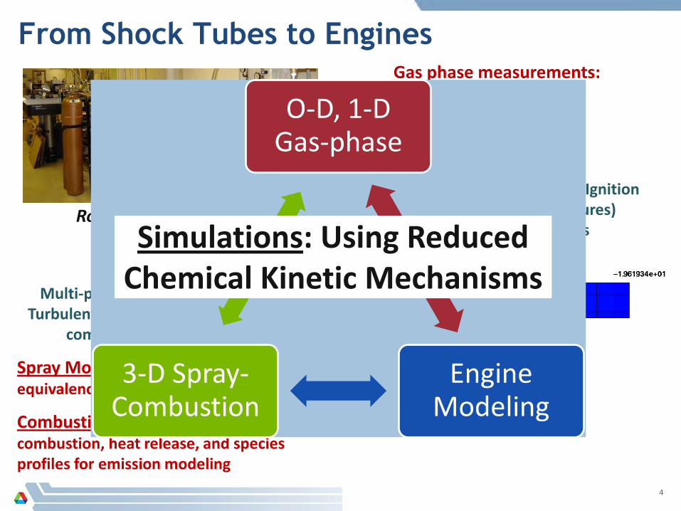
Engine Processes: Multi-physic, Multi-scale, Multi-phase,
Turbulent, Heat-transfer, moving surfaces, complex combustion chemistry
Spray Modeling: Predict accurate equivalence ratio distribution
Combusting Modeling: Predict ignition, combustion, heat release, and species profiles for emission modeling
Gas phase measurements: Temperature, speciation
Operating Range: Temperature: 900-2000K
Pressure: 0.1-50bar Equivalence ratio: 0.5-2.0 (Note: Ignition
actually occurs at richer mixtures) Reaction times: Up to 2ms
Rob Tranter’s shock-tube
From Shock Tubes to Engines
4
O-D, 1-D Gas-phase
Engine Modeling
3-D Spray- Combustion
Simulations: Using Reduced Chemical Kinetic Mechanisms

3-D Integrated Modeling Approach
5
Primary Breakup
Inner Nozzle Flow
Spray
Combustion Ignition
Detailed inner-nozzle flow modeling Spray Modeling: KH-ACT primary breakup model Aerodynamics, Cavitation, Turbulence
Validation: X-ray radiography data Detailed Chemistry: n-heptane – Diesel surrogate n-dodecane – Diesel surrogate Methyl Decanoate – Biodiesel surrogate Validation: Constant-volume vessel (Sandia National Laboratory) Engine data (Argonne National Laboratory)
Conceptual Combustion Model from
Sandia National Laboratory
Emissions

6
Primary Breakup Model
6
KH-ACT (Kelvin-Helmholtz-Aerodynamics Cavitation Turbulence) Model*
*Som et al., SAE Paper No. 2009-01-0838 Som et al., Combustion and Flame 2010
KH KH-RT
Fdrag
Urel
FdragFdrag
Urel
Length and time scales are calculated:
o Cavitation induced breakup: Based on bubble collapse and burst times
o Turbulence induced breakup : Based on k-ε model
o Aerodynamically induced breakup: Based on Kelvin-Helmholtz (KH) and Rayleigh Taylor (RT) instability
Dominant ratio of length/time scale causes breakup
Extensive model validation against x-ray data at Argonne
Accurately predict fuel distribution (equivalence ratio)!!
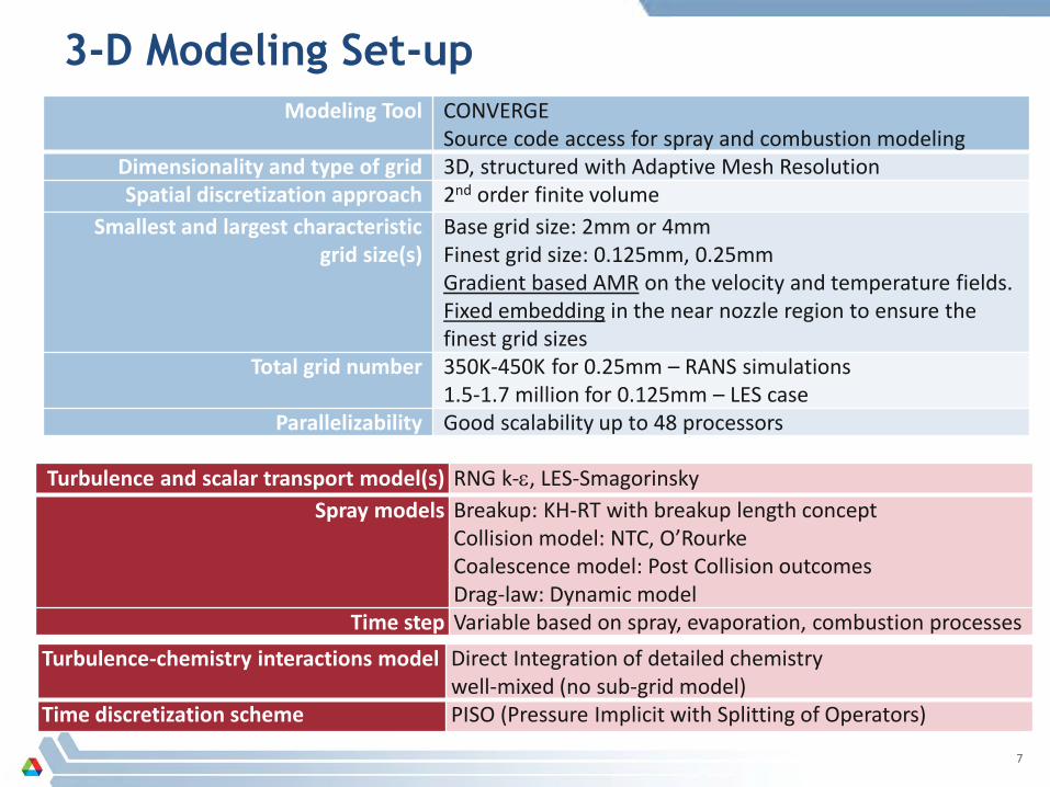
3-D Modeling Set-up
7
Modeling Tool CONVERGE Source code access for spray and combustion modeling
Dimensionality and type of grid 3D, structured with Adaptive Mesh Resolution Spatial discretization approach 2nd order finite volume
Smallest and largest characteristic grid size(s)
Base grid size: 2mm or 4mm Finest grid size: 0.125mm, 0.25mm Gradient based AMR on the velocity and temperature fields. Fixed embedding in the near nozzle region to ensure the finest grid sizes
Total grid number 350K-450K for 0.25mm – RANS simulations 1.5-1.7 million for 0.125mm – LES case
Parallelizability Good scalability up to 48 processors
Turbulence and scalar transport model(s) RNG k-, LES-Smagorinsky
Spray models Breakup: KH-RT with breakup length concept Collision model: NTC, O’Rourke Coalescence model: Post Collision outcomes Drag-law: Dynamic model
Time step Variable based on spray, evaporation, combustion processes
Turbulence-chemistry interactions model Direct Integration of detailed chemistry well-mixed (no sub-grid model)
Time discretization scheme PISO (Pressure Implicit with Splitting of Operators)

Spray Validation against X-ray Data
8
Spray Dispersion accurately captured by only the KH-ACT model. KH model under-predicts spray spreading
X-ray radiography Data: Ramirez et al., JEF 2009
The spray loses half of its initial velocity within the first 6 mm
0
0.2
0.4
0.6
0.8
1
0 3 6 9 12 15
Nor
mal
ized
Spr
ay A
xial
Vel
ocity
Axial Position (mm)
X-ray DataKH modelKH-ACT model
0
20
40
60
80
100
120
140
-1.5 -1.0 -0.5 0.0 0.5 1.0 1.5
Proj
ecte
d M
ass
Den
sity
[μg/
mm
2 ]
Transverse position (mm)
X-ray DataKH ModelKH-ACT Model
7 mm from nozzle exit
0.3 mm from nozzle exit
Accurate fuel distribution (equivalence ratio) is critical for reliable combustion
predictions!

Development of Reduced
Reaction Mechanisms
Biodiesel surrogates:
(from LLNL) Methyl Decanoate (MD)
Methyl 9 Decenoate (MD9D)
n-Heptane (NHPT)
9

Methyl Palmitate (C17H34O2)
Methyl Stearate (C19H38O2)
Methyl Oleate (C19H36O2)
Methyl Linoleate (C19H34O2)
Methyl Linolenate (C19H32O2)
Composition of Biodiesels
Biodiesel is a mixture of long-chain, oxygenated, unsaturated
components
n-heptane, n-C7H16
10
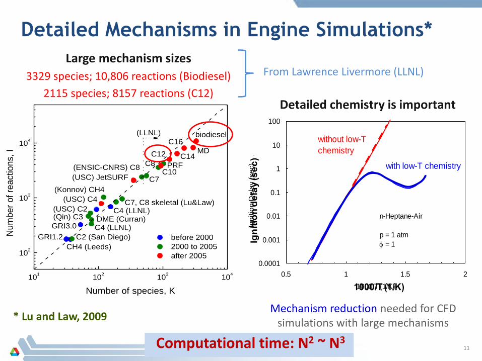
Detailed Mechanisms in Engine Simulations*
Detailed chemistry is important
Large mechanism sizes
3329 species; 10,806 reactions (Biodiesel)
2115 species; 8157 reactions (C12)
101
102
103
104
102
103
104
biodiesel
(USC) JetSURF
before 2000
2000 to 2005
after 2005
C8(ENSIC-CNRS) C8
C4 (LLNL)
(Konnov) CH4
C4 (LLNL)
C2 (San Diego)
CH4 (Leeds)
MD
C16
C14C12
C10
(USC) C4
(USC) C2
PRF
C7
C7, C8 skeletal (Lu&Law)
DME (Curran)(Qin) C3
GRI3.0
Nu
mb
er
of
rea
ctio
ns,
I
Number of species, K
GRI1.2
(LLNL)
0.0001
0.001
0.01
0.1
1
10
100
0.5 1 1.5 2
1000/T (1/K)
Ign
itio
n D
ela
y (
se
c)
,
with low-T chemistry
without low-T
chemistry
n-Heptane-Air
p = 1 atm
f = 1
1000/T (1/K)
Igni
tion
dela
y (s
ec)
Mechanism reduction needed for CFD simulations with large mechanisms
* Lu and Law, 2009
11
From Lawrence Livermore (LLNL)
Computational time: N2 ~ N3
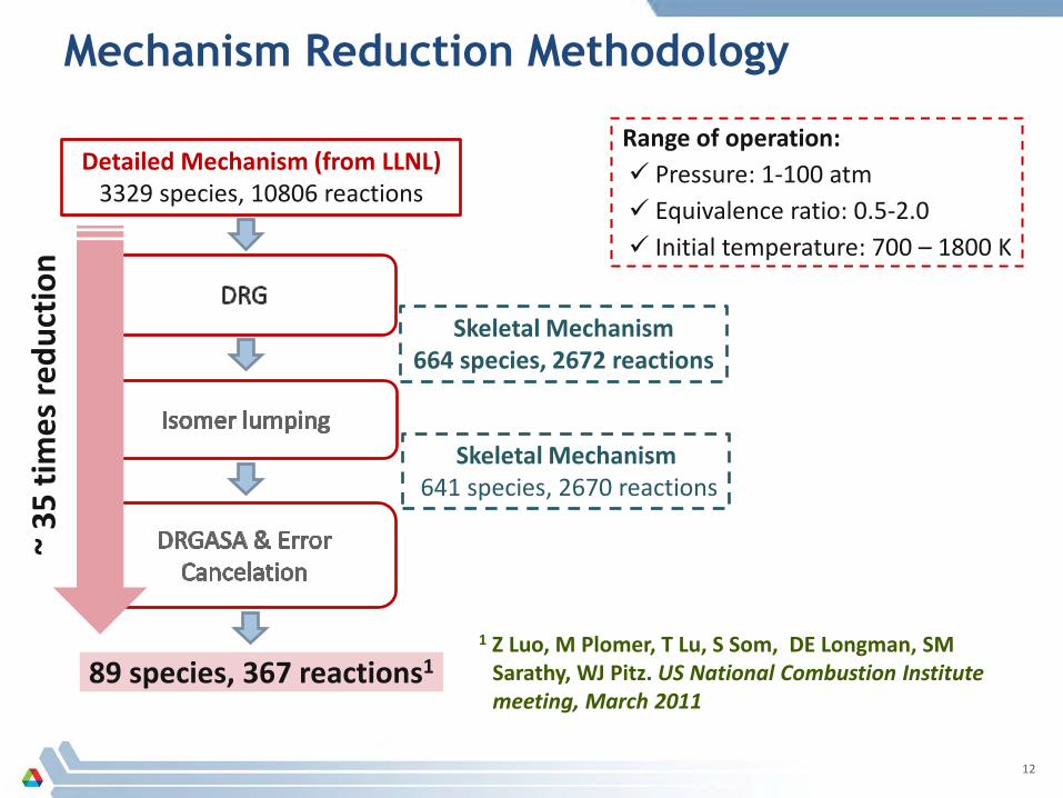
Mechanism Reduction Methodology
Detailed Mechanism (from LLNL) 3329 species, 10806 reactions
Skeletal Mechanism 664 species, 2672 reactions
Skeletal Mechanism 641 species, 2670 reactions
Range of operation:
Pressure: 1-100 atm
Equivalence ratio: 0.5-2.0
Initial temperature: 700 – 1800 K
1 Z Luo, M Plomer, T Lu, S Som, DE Longman, SM Sarathy, WJ Pitz. US National Combustion Institute meeting, March 2011
89 species, 367 reactions1
12
~ 3
5 t
ime
s re
du
ctio
n

Validation against Idealized Combustion
Systems: Biodiesel
13
Jet-Stirred Reactor (JSR) Dagaut et al. PCI 2007
0.74 0.76 0.78 0.80 0.82 0.84 0.8610
-5
10-4
10-3
10-2
Skeletal
Igni
tion
Del
ay T
ime,
s
1000/T, K-1
MD - O2 -Ar
p = 7 atm
f = 0.09
Detailed
Experiments
Shock-Tube Haylett et al. 2011
89 species mechanism is able to predict ignition and species characteristics very well!
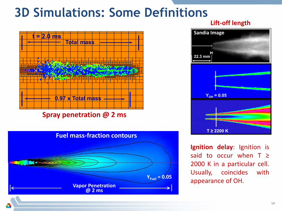
3D Simulations: Some Definitions
14
Total mass
0.97 x Total mass
t = 2.0 ms
Spray penetration @ 2 ms
Fuel mass-fraction contours
YFuel = 0.05
Vapor Penetration @ 2 ms
Lift-off length
T ≥ 2200 K
YOH = 0.05
22.3 mm
Sandia Image
Ignition delay: Ignition is said to occur when T ≥ 2000 K in a particular cell. Usually, coincides with appearance of OH.
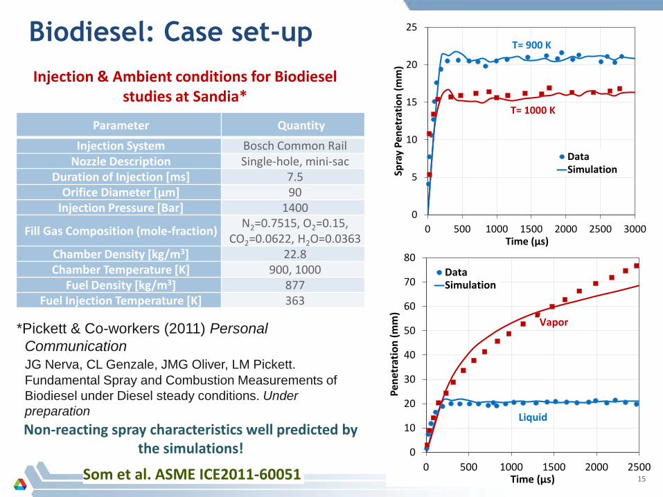
Biodiesel: Case set-up
Parameter Quantity
Injection System Bosch Common Rail Nozzle Description Single-hole, mini-sac
Duration of Injection [ms] 7.5 Orifice Diameter [µm] 90
Injection Pressure [Bar] 1400
Fill Gas Composition (mole-fraction) N2=0.7515, O2=0.15,
CO2=0.0622, H2O=0.0363 Chamber Density [kg/m3] 22.8 Chamber Temperature [K] 900, 1000
Fuel Density [kg/m3] 877 Fuel Injection Temperature [K] 363
*Pickett & Co-workers (2011) Personal
Communication
JG Nerva, CL Genzale, JMG Oliver, LM Pickett.
Fundamental Spray and Combustion Measurements of
Biodiesel under Diesel steady conditions. Under
preparation
0
10
20
30
40
50
60
70
80
0 500 1000 1500 2000 2500
Pe
net
rati
on
(m
m)
Time (µs)
DataSimulation
Liquid
Vapor
Injection & Ambient conditions for Biodiesel studies at Sandia*
0
5
10
15
20
25
0 500 1000 1500 2000 2500 3000
Spra
y P
en
etra
tio
n (
mm
)
Time (µs)
DataSimulation
T= 900 K
T= 1000 K
Non-reacting spray characteristics well predicted by the simulations!
15 Som et al. ASME ICE2011-60051
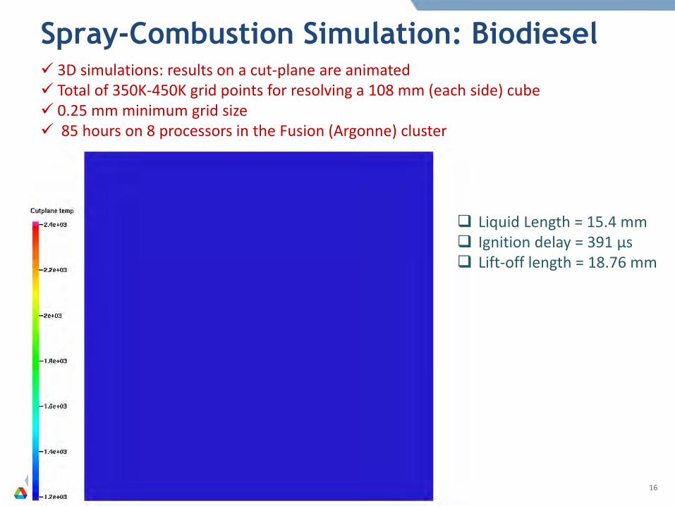
Spray-Combustion Simulation: Biodiesel
16
3D simulations: results on a cut-plane are animated Total of 350K-450K grid points for resolving a 108 mm (each side) cube 0.25 mm minimum grid size 85 hours on 8 processors in the Fusion (Argonne) cluster
Liquid Length = 15.4 mm Ignition delay = 391 μs Lift-off length = 18.76 mm

Validation of Biodiesel Reaction Mechanisms
@ T = 1000 K Ignition Delay (µs)
Sandia Data 396
89 species 391
ERC-Bio mechanism 220
Data from Sandia National Laboratory
17
OH-chemiluminescence
2.04 18.76 mm
89 species mechanism
2.67 10.12 mm
ERC-bio mechanism
@ T = 1000 K
CSE is further assessing the ERC-bio mechanism!
OH-chemiluminescence
2.04 18.76 mm
89 species mechanism
2.67 10.12 mm
ERC-bio mechanism
Simulations plot OH contours at a cut-plane
ERC-bio mechanism: (Methyl Butanoate +
NHPT) 41 species and 150 reactions. SAE
Paper No. 2008-01-1378
ERC-bio mechanism (using MB as a
surrogate) under predicts lift-off length and
ignition delay and consequently over-
predicts equivalence ratio
89 species mechanism (using MD as a
surrogate) captures ignition delay, flame lift-
off length, and equivalence ratio very well
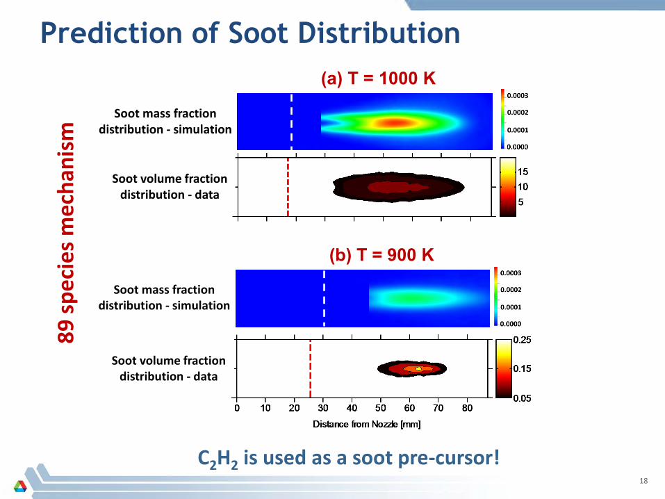
Prediction of Soot Distribution
18
Soot volume fraction distribution - data
(a) T = 1000 K
Soot mass fraction distribution - simulation
Soot volume fraction distribution - data
(b) T = 900 K
Soot mass fraction distribution - simulation
89
sp
eci
es
me
chan
ism
C2H2 is used as a soot pre-cursor!
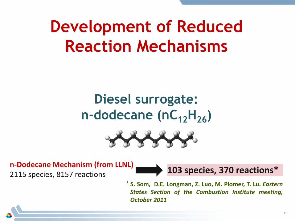
Development of Reduced
Reaction Mechanisms
Diesel surrogate:
n-dodecane (nC12H26)
19
n-Dodecane Mechanism (from LLNL) 2115 species, 8157 reactions 103 species, 370 reactions*
* S. Som, D.E. Longman, Z. Luo, M. Plomer, T. Lu. Eastern States Section of the Combustion Institute meeting, October 2011

Validation against Shock Tube data
20
0.7 0.8 0.9 1.0 1.1 1.2 1.3
10-5
10-4
10-3
10-2
p = 40 atm
Ignitio
n D
ela
y, s
1000/T, K-1
f = 0.5
p = 6 atm
Simulations
Experiments
n-dodecane/O2+Ar
(a)
0.8 0.9 1.0 1.1 1.2 1.3 1.4 1.510
2
103
104
Ignitio
n D
ela
y T
ime, s
1000/T, K-1
f = 1
p = 20 atm
Simulations
Experiments
n-dodecane/air
(b)
Experimental data from: Vasu et al. Proc. of Combustion Institute 2009
Black symbols: experimental data from: Davidson et al. Combustion and Flame 2008 Red symbols: experimental data from: Shen et al. Energy and Fuels 2009
103 species, 370 reactions: n-dodecane reduced mechanism
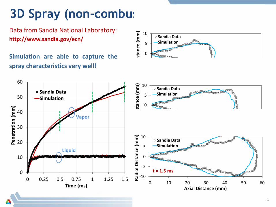
3D Spray (non-combusting) Validation
21
Data from Sandia National Laboratory:
http://www.sandia.gov/ecn/
Simulation are able to capture the
spray characteristics very well!
0
10
20
30
40
50
60
0 0.25 0.5 0.75 1 1.25 1.5
Pe
net
rati
on
(m
m)
Time (ms)
Sandia DataSimulation
Liquid
Vapor
-10
-5
0
5
10
0 10 20 30 40 50 60
Ra
dia
l Dis
tan
ce (
mm
)
Axial Distance (mm)
Sandia DataSimulation
t = 0.5 ms
-10
-5
0
5
10
0 10 20 30 40 50 60
Ra
dia
l Dis
tan
ce (
mm
)Axial Distance (mm)
Sandia DataSimulation
t = 1.0 ms
-10
-5
0
5
10
0 10 20 30 40 50 60
Ra
dia
l Dis
tan
ce (
mm
)
Axial Distance (mm)
Sandia DataSimulation
t = 1.5 ms
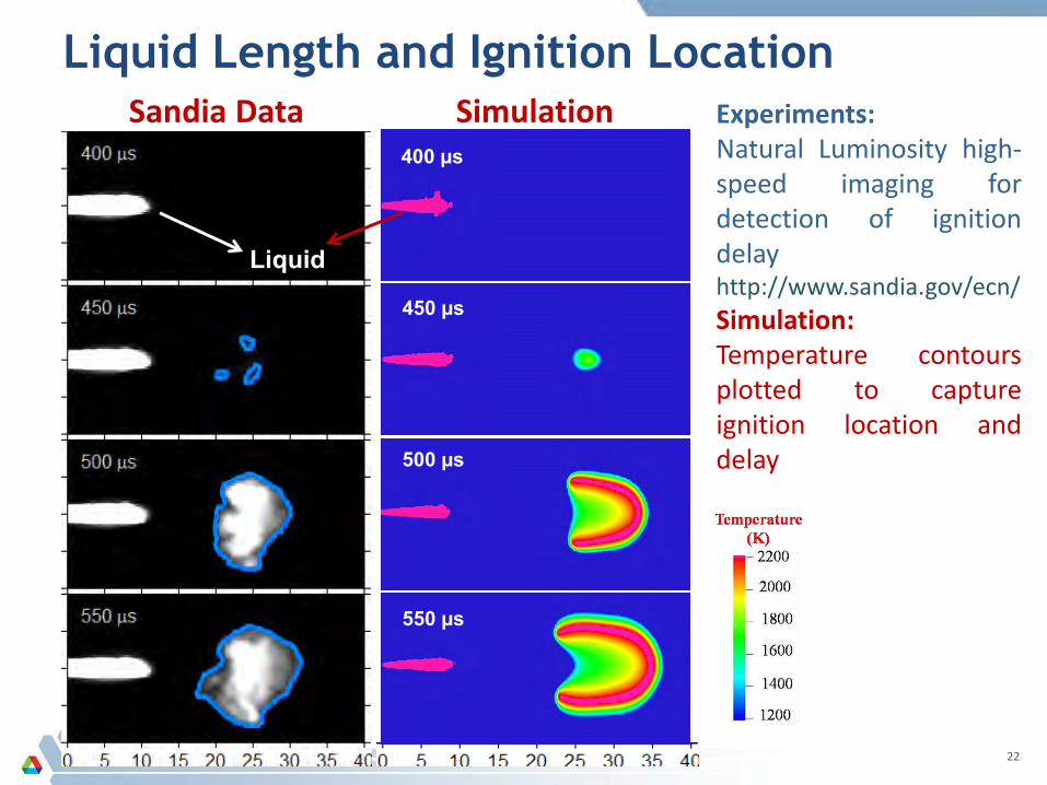
Liquid Length and Ignition Location
22
Sandia Data400 µs
450 µs
500 µs
550 µs
Simulation
Liquid
Experiments: Natural Luminosity high-speed imaging for detection of ignition delay http://www.sandia.gov/ecn/
Simulation: Temperature contours plotted to capture ignition location and delay
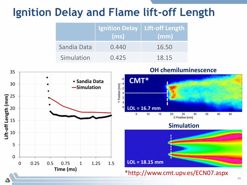
Ignition Delay and Flame lift-off Length
23
Ignition Delay (ms)
Lift-off Length (mm)
Sandia Data 0.440 16.50
Simulation 0.425 18.15
0
5
10
15
20
25
30
35
0 0.25 0.5 0.75 1 1.25 1.5
Lift
-off
Le
ngt
h (
mm
)
Time (ms)
Sandia DataSimulation
*http://www.cmt.upv.es/ECN07.aspx
CMT*
LOL = 16.7 mm
OH chemiluminescence
LOL = 18.15 mm
Simulation

Bringing it all together!
Diesel surrogates:
n-heptane (nC7H16)
24
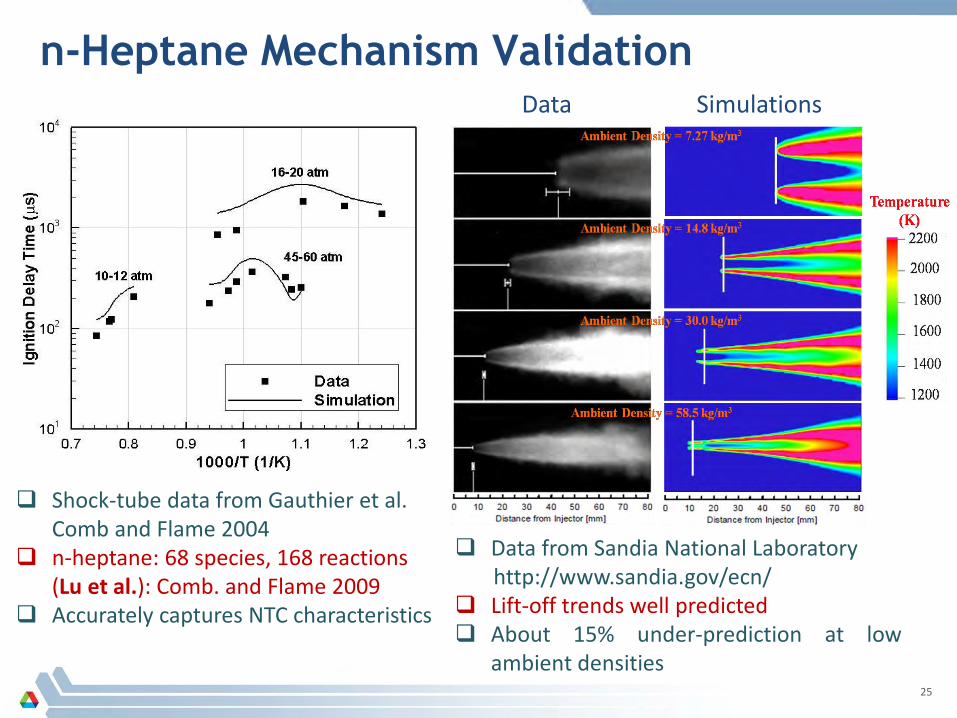
n-Heptane Mechanism Validation
25
Shock-tube data from Gauthier et al. Comb and Flame 2004
n-heptane: 68 species, 168 reactions (Lu et al.): Comb. and Flame 2009
Accurately captures NTC characteristics
Data from Sandia National Laboratory http://www.sandia.gov/ecn/ Lift-off trends well predicted About 15% under-prediction at low
ambient densities
Data Simulations

Engine Simulation
26
Single-Cylinder Caterpillar Engine
Fuel Diesel # 2 (n-heptane surrogate)
Engine speed 1500 rpm
Compression ratio 16:1
Injection Pressure 1100 bar (peak)
Duration of Injection ~ 3 ms
2 < φ < 5
@ 20 ˚CA
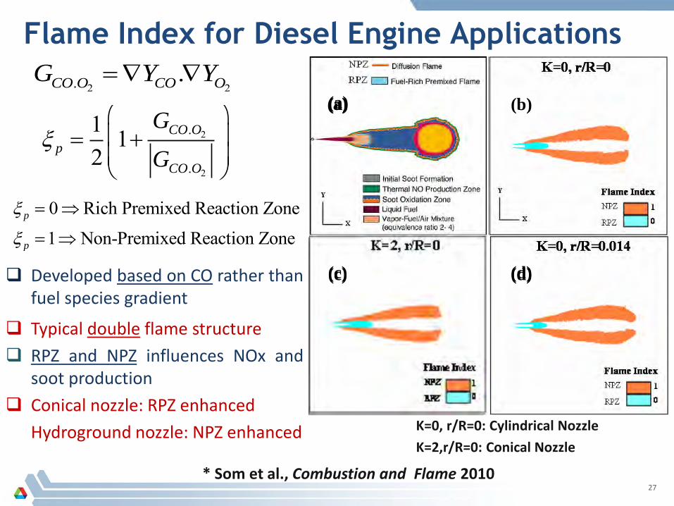
Flame Index for Diesel Engine Applications
27
2
2
.
.
1 12
CO O
p
CO O
G
G
2 2. .CO O CO OG Y Y
0 Rich Premixed Reaction Zone
1 Non-Premixed Reaction Zonep
p
Developed based on CO rather than fuel species gradient
(a) (b)
(c) (d)
Typical double flame structure
RPZ and NPZ influences NOx and soot production
Conical nozzle: RPZ enhanced
Hydroground nozzle: NPZ enhanced
(a) (b)
(c) (d)
K=0, r/R=0: Cylindrical Nozzle
K=2,r/R=0: Conical Nozzle
(a) (b)
(c) (d)
* Som et al., Combustion and Flame 2010

Summary
28
Systematic mechanism reduction performed (starting from detailed mechanism from LLNL) for operation under compression ignition engine conditions MD+MD9D+NHPT: Used as a biodiesel surrogate n-dodecane and n-heptane: Used as diesel surrogates
The reaction rates of these reduced mechanism are not tuned to match any specific data-set
Robust validation performed against idealized combustion system data: 0-D systems: Shock tube, Jet stirred reactor 1-D system: Premix flame speed, counter flow diffusion flames 3-D spray combustion system
The reduced mechanism matched the experimental data very well under all the condition investigated
Larger mechanisms and molecules were observed to predict ignition and combustion characteristics better compared to the smaller counterparts
Engine simulations were performed using the systematically reduced reaction mechanisms. These mechanisms were able to capture 3-D ignition and combustion characteristics very well
29
Thank You!!
Contact: [email protected]
http://www.transportation.anl.gov/engines/multi_dim_model_home.html
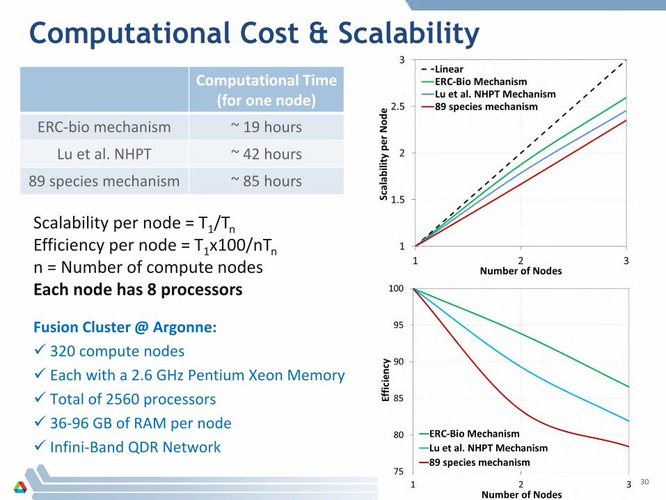
Computational Cost & Scalability
Computational Time (for one node)
ERC-bio mechanism ~ 19 hours
Lu et al. NHPT ~ 42 hours
89 species mechanism ~ 85 hours
Fusion Cluster @ Argonne:
320 compute nodes
Each with a 2.6 GHz Pentium Xeon Memory
Total of 2560 processors
36-96 GB of RAM per node
Infini-Band QDR Network
Scalability per node = T1/Tn
Efficiency per node = T1x100/nTn
n = Number of compute nodes Each node has 8 processors
30