Validation of Office Chair for BIFMA standard using FEA Toolijsrst.com/paper/1582.pdf ·...
9
IJSRST1737155 | Received : 15 Oct 2017 | Accepted : 29 Oct 2017 | September-October-2017 [(3) 7: 881-889 ] © 2017 IJSRST | Volume 3 | Issue 7 | Print ISSN: 2395-6011 | Online ISSN: 2395-602X Themed Section: Science and Technology 881 Validation of Office Chair for BIFMA standard using FEA Tool Vishal D. Chaudhary, Prof. Dr. Santosh G. Taji, Prof. Harshad S. Bawiskar 1 Department of Mechanical Engineering, Shree Ramchandra College of engineering, Lonikand, Pune, Maharashtra, India 2 Department of Mechanical Engineering, Government Polytechnic, Ahmednagar, Maharashtra, India 3 Department of Mechanical Engineering, Shree Ramchandra College of engineering, Lonikand, Pune, Maharashtra, India ABSTRACT The study presents finite element analysis (FEA) based validation of a new chair concept with unique connecting mechanism obeying business & institutional furniture manufacturing association (BIFMA) standard. Business & institutional furniture manufacturing association standard is followed by all commercial and office chair manufacturer for global business. However, it is not followed for local business because chairs manufacturing lacks design innovations. The work is an effort to validate the strength and quality enhancement upon application of business & institutional furniture manufacturing association on chair design. Linear structural analysis of given load case is carried out using finite element analysis software. Hypermesh is used for preprocessing; LS-Dyna for solving mathematical equations and Hyperview is used for result interpretation. Design modifications are incorporated iteratively so that the model fits into the regulation. Comparison of the FEA results and experimental test results was done to verify the obtained results. Keywords: CAD Model, Material Datasheet, Finite Element Analysis, BIFMA Standard, Nonlinear Structural Analysis I. INTRODUCTION In the era focused on technological advancement, office chair is one of the most basic necessities with much influence on the productivity of employees through the extent of comfort and flexibility it offers. Simultaneously, the chair is supposed to be durable to reduce the maintenance cost to the firm. Office chairs are often used by the user working in front of a computer. Office chair is meant to keep the users back in an upright position, facilitating the arm rest on table at 90 degree while the user is sitting in front of a computer or reading and writing on paper. Additionally, the office chair should allow some adjustments on the chair to suit individual‟s comfort as mostly people have long working hours that require sitting for long duration. A comfortable chair is characterized by ability to switch its positions, height and angle of the back and its strength. The durability of office chair is crucial so that it can also sustain obese individual. Also, backrest strength is crucial as its breakage can cause accidents that may be fatal if it leads to serious head injury. Business & institutional furniture manufacturing association (BIFMA) standard, provides regulations to ensure the strength and quality of chair suitable for rough use. For validation of chair quality, BIFMA standard provides test set up of process of testing on which finite element analysis (FEA) model [1] is built and respective analysis were run. In this study, all major component of Chair are analysed for Backrest strength test based on BIFMA by using FEA tool. Development of BIFMA standards is organized by BIFMA Engineering Committee, which involves formation of working groups and canvass lists, drafting & revision of standards, publication and frequent review of accepted standards. The standard is aimed at providing a common basis for evaluating safety, durability, and structural adequacy of a specified furniture, irrespective of construction materials. The standards define specific tests, laboratory equipment and test conditions, and minimum acceptance levels to be used in evaluating products [2]. The analytical solutions considering two type of approach in compliance with static and dynamic stress analysis are performed utilizing Hypermesh for model building (Meshing) ,
Transcript of Validation of Office Chair for BIFMA standard using FEA Toolijsrst.com/paper/1582.pdf ·...

IJSRST1737155 | Received : 15 Oct 2017 | Accepted : 29 Oct 2017 | September-October-2017 [(3) 7: 881-889 ]
© 2017 IJSRST | Volume 3 | Issue 7 | Print ISSN: 2395-6011 | Online ISSN: 2395-602X Themed Section: Science and Technology
881
Validation of Office Chair for BIFMA standard using FEA Tool Vishal D. Chaudhary, Prof. Dr. Santosh G. Taji, Prof. Harshad S. Bawiskar
1Department of Mechanical Engineering, Shree Ramchandra College of engineering, Lonikand, Pune, Maharashtra, India
2Department of Mechanical Engineering, Government Polytechnic, Ahmednagar, Maharashtra, India
3Department of Mechanical Engineering, Shree Ramchandra College of engineering, Lonikand, Pune, Maharashtra, India
ABSTRACT
The study presents finite element analysis (FEA) based validation of a new chair concept with unique connecting
mechanism obeying business & institutional furniture manufacturing association (BIFMA) standard. Business &
institutional furniture manufacturing association standard is followed by all commercial and office chair
manufacturer for global business. However, it is not followed for local business because chairs manufacturing lacks
design innovations. The work is an effort to validate the strength and quality enhancement upon application of
business & institutional furniture manufacturing association on chair design. Linear structural analysis of given load
case is carried out using finite element analysis software. Hypermesh is used for preprocessing; LS-Dyna for solving
mathematical equations and Hyperview is used for result interpretation. Design modifications are incorporated
iteratively so that the model fits into the regulation. Comparison of the FEA results and experimental test results was
done to verify the obtained results.
Keywords: CAD Model, Material Datasheet, Finite Element Analysis, BIFMA Standard, Nonlinear Structural
Analysis
I. INTRODUCTION
In the era focused on technological advancement, office
chair is one of the most basic necessities with much
influence on the productivity of employees through the
extent of comfort and flexibility it offers.
Simultaneously, the chair is supposed to be durable to
reduce the maintenance cost to the firm. Office chairs
are often used by the user working in front of a
computer. Office chair is meant to keep the users back in
an upright position, facilitating the arm rest on table at
90 degree while the user is sitting in front of a computer
or reading and writing on paper. Additionally, the office
chair should allow some adjustments on the chair to suit
individual‟s comfort as mostly people have long
working hours that require sitting for long duration. A
comfortable chair is characterized by ability to switch its
positions, height and angle of the back and its strength.
The durability of office chair is crucial so that it can also
sustain obese individual. Also, backrest strength is
crucial as its breakage can cause accidents that may be
fatal if it leads to serious head injury.
Business & institutional furniture manufacturing
association (BIFMA) standard, provides regulations to
ensure the strength and quality of chair suitable for
rough use. For validation of chair quality, BIFMA
standard provides test set up of process of testing on
which finite element analysis (FEA) model [1] is built
and respective analysis were run. In this study, all major
component of Chair are analysed for Backrest strength
test based on BIFMA by using FEA tool.
Development of BIFMA standards is organized by
BIFMA Engineering Committee, which involves
formation of working groups and canvass lists, drafting
& revision of standards, publication and frequent review
of accepted standards. The standard is aimed at
providing a common basis for evaluating safety,
durability, and structural adequacy of a specified
furniture, irrespective of construction materials. The
standards define specific tests, laboratory equipment and
test conditions, and minimum acceptance levels to be
used in evaluating products [2]. The analytical solutions
considering two type of approach in compliance with
static and dynamic stress analysis are performed
utilizing Hypermesh for model building (Meshing) ,

International Journal of Scientific Research in Science and Technology (www.ijsrst.com)
882
Radioss and LS Dyna [3] for solving and Hyperview for
result interpretation [4].
In this study displacement, stress, and strain are
investigated and the von Misses stress obtain from the
FEA is compared with yield stress of respective material
to identify whether chair satisfies the BIFMA standard
criteria for given load case. Design modification is
performed in the cases of failed tests and followed by
similar FEA analysis until the chair pass in given load
case. In order to find best possible design under some
given circumstances, design method is generally an
iterative process. Designer proposes a design based upon
old design references and then analytical method is used
for verification, where stress and displacement
characteristics of the frame are maintained analytically.
The validation is often complemented by application of
mechanical tests on a prototype. Further, possible
modifications are done to improve the design and satisfy
unfulfilled requirements. The new design is analysed,
and the process is iterated to achieve optimal design.
Similar approach has been applied in this study, to
obtain office chair design which satisfies BIFMA
standard.
Office chair design is validated for all required tests as
per BIFMA standard to ensure safety and durability. The
studied chair design is based on a new concept, having
all structural parts with plastic material. Therefore, it is
important to check the strength of chair structure for
user safety.
The proposed of work include
Literature review of requisites of BIFMA standard.
Study of FEA procedure for BIFMA standard.
Detailed design and mechanism study of Office
chair
Identification of force transfer path for load case.
Modeling of chair in finite element software
(Hypermesh)
Application of loading and boundary condition
Set up of specified test in finite element model
Submission of finite element model to solver to
solve complete algorithm.
Result interpretation against allowable limit, given
test standard using post processing software
(Hyperview)
Von Misses stresses and deflection
Design modification in chair structure (if required)
II. Literature Review
The material presented in BIFMA standards was
developed by the members of BIFMA International and
are reviewed by a broad representation of interested
parties, government organizations and commercial
testing and procurement and interior design
organizations [3].
BIFMA standard defines specific tests, laboratory
equipment, conditions of test, and recommended
minimum level to be used during the test and for safety
evaluation, durability evaluation, and to check structural
adequacy of general-purpose office chairs. BIFMA
standard is first proposed in 1974 by the BIFMA
Engineering committee, the subcommittee on chair
standards conducts frequent reviews of the BIFMA
standard to ensure that tests precisely describe the proper
method of evaluations. The reviews produced revisions
and additions to the various test procedures that improve
the procedures and provide consistency. BIFMA
standard follows the guidelines of ANSI (American
National Standards Institute) accredited standards
developer, and the BIFMA standard was subsequently
submitted to the American National Standards Institute
for approval as an American National Standard. BIFMA
received approval by ANSI [10].
The American National Standards Institute (ANSI)
approved the newly developed safety and performance
standard for educational seating: ANSI/BIFMA X6.1-
2012: Educational Seating – Tests [9]. The Business and
Institutional Furniture manufacturers Association‟s
(BIFMA) Seating Subcommittee created industry
consensus standard using several test methods from
existing ANSI/BIFMA seating standards as a basis.
ANSI/BIFMA X6.1-2012 involved the development of
several unique tests relevant to the educational
environment, including tests for educational products,
such as convertible benches, chair desks, and backpack
hooks.
Emerging research suggests that asymmetry may be an
important new dimension in the design of low back
support for chairs. A recent study to quantify the amount
of support users wanted in the lower back found that

International Journal of Scientific Research in Science and Technology (www.ijsrst.com)
883
approximately 70% of seated individuals is more
comfortable when allowed to self-select asymmetric low
back support – more support to the left side of the back
or vice versa. Asymmetry may be considered by the
designers of lumbar supports for chairs in order to
maximize comfort while sitting [7].
Objectives
To design office chair and study working
mechanism of office chair
To perform design validation of Office chair using
FEA
To test the structural strength of design and check if
meets the BIFMA standard
To perform iterative design modifications and
validation using FEA until the design satisfies
BIFMA standard
Backrest Strength Test
The purpose of this test is to evaluate the ability of the
chair to withstand stresses such as those caused by the
user exerting a rearward force on the backrest of the
chair.
III. Methodology
The study comprises of three major steps: preprocessing,
equation solving using LS-Dyna, and post processing.
The details of the steps are illustrated in Fig. 1. The
prototype thus obtained goes through experimental
testing and results of experimental test should show
close approximation with FEA result. Chair should pass
the BIFMA standard in experimental testing too. The
experimental testing is beyond the scope of our study
and is limited to prototype generation.
Figure 1: Flowchart of FEA
Test Setup
Step 1
The chair is placed on a test platform in an upright
position and the base is restrained from movement, but
movement of the backrest or arm of the chair is not
restricted. Fig.2. shows one acceptable method of
restraining the chair [9].
Step 2
If adjustable features are available, all adjustments
should be set at normal use conditions, except for the
height adjustable pivoting backrest which should have
pivot point set at its maximum height or 406 mm
(whichever is less).
Step 3
After making the above adjustment, a point is
determined, 406 mm and 452mm above the seat. These
points are marked on the vertical centre line of the
backrest.
Preprocessing
Meshing Model
Building
To solve the above problem by
software (LS-Dyna)
Element type
Mesh type
Software used
Thickness
assignment
Loading
condition
Boundary
condition
Material
assignment
Connection
Prototype
Post Processing Result interpretation
YES
NO Design
modification
Satisfies
BIFMA
Standard?

International Journal of Scientific Research in Science and Technology (www.ijsrst.com)
884
i) If the top of the load bearing structure/surface of the
backrest is greater than or equal to 452 mm above
the seat, the Centre of the form fitting device should
be positioned above the seat.
ii) If the top of the load bearing structure/surface of the
backrest is less than 452 mm above the seat, top of
the form fitting device should be positioned even
with the top of the load bearing structure/surface.
iii) If the unit has a pivoting backrest that stops at a
position less than or equal to 20 degrees rearward,
form fitting device should be positioned like
previous rule. If the unit has a pivoting backrest that
stops at a position greater than 20 degrees rearward
of the backrest, the centre of the form fitting device
should be positioned at the height of the pivoting
point.
Step 4
A loading device (front push or back pull) is attached to
the horizontal centre of the backrest as determine above.
With the backrest at its back stop position, a force is
applied that is initial 90 degrees ± 10 degrees to the
plane of the backrest. Force is not intended to maintain
90 degrees throughout the loading of the backrest. If the
load is applied with a cable and pulley system, the cable
must initially be a minimum of 762 mm in length from
the attachment point to the pulley.
Acceptance level
There should be no loss of serviceability to the chair.
Induced stresses should be less than the yield of the
material.
Test procedure
Step 1
A force of 890 N should be applied to the backrest at the
backstop position for one minute. If the backrest/tilt lock
mechanism will not accept the load due to gradual
slipping of the adjustment mechanism during the load
application, the backrest is set to its most rearward
position, and then the specified load is applied.
Step 2
The load is removed. Fig. 2 shows loading and boundary
condition for FEA as per BIFMA.
Figure 2: Office Chair test setup (BIFMA standard)
Connection Scheme
When all the components are connected with each other
as per given connection scheme, it forms the chair
assembly (Fig. 3).
Figure 3: Chair Assembly
Figure 4. Study of connection scheme

International Journal of Scientific Research in Science and Technology (www.ijsrst.com)
885
Connections of chair-components are shown in Fig. 4.
The major connecting components are screw, spring,
heat stakes and contacts.
Finite Element analysis
Preprocessing is a discretization process known as
Meshing, where the elements are known as „Finite‟
because of their finite size [1]. Hypermesh is FEA
software in which engineering problem solution can be
obtained at a reasonable financial cost and time duration.
The procedure for the is followed by three procedures.
Pre-processing involves fixing of the geometry,
importing(if needed) for free edges and reducing the
model to a mathematical model using meshing and
creating finite elements [10].Geometry Fixing means
conversion of the CAD model into FEA geometry,
which makes Hypermesh simple to capture all the
features in the geometry. Hypermesh is one the most
popular tool for meshing, because it is user friendly and
each element can be controlled during meshing. The
choice of the meshing element type 2-d or 3-d isdone by
the user based on his/her past experiences [4].
Step 1
The geometry is imported in Hypermesh and then
topology option is selected tovisualize the free edges (if
any)as red line and green edges with joint surfaces. The
surfaces with free edges are fixed by the creation of
surface. Toggle edge option is used for fixing edges.
Upon cleaning up the surfaces some of the green edges
are suppressed so to get a good quality mesh with good
flow of the elements and lesser failed elements. The
suppression of the edges are made according in such a
way that the elements do not collapse. The editing of the
shared edges are based on the behavior of the finite
elements and experience in analysis.
Hypermesh follows below unit system.
Displacement: mm
Modulus: MPa
Force: Newton
Mass: Tonne
Density: Tonne/mm3
Step 2
The cleaning of the surfaces isdone to mesh the
geometry. Before the mesh the unnecessary parts such as
the nut bolts, bushings, and spherical joints are
eliminated. As the nut bolts, rigid joints can be replaced
by the 1-d rigid and joints in Hypermesh. This way
saves the meshing time and errors coming from meshing
the parts. The links connections were kept for the
analysis.
Fig. 5 shows meshing of Seat Base and Spine with
reliable elements and assembly of meshed chair.
Figure 5. Preprocessing/Meshing of office chair
Step 3
After meshing and material assignment, mass is checked.
Mass of FE model should match with actual model. In
our study, mass of actual model is 10.98 Kg whereas
mass of FE model is 10.73 Kg (Fig. 6.). As, there is no
objectionable difference in mass hence the meshing
process is right.
Actual mass = 10.98 Kg
Mass of finite element model is given in below image
Fig. 6.
Figure 6. Mass of finite element Model and related
details
Analysis involves definition of material properties,
geometry, boundary conditions and loading conditions.
These are the steps in setting up the analysis in order to
be followed with a solution needed. In this case
nonlinear static analysis is carried out with given force
at given location as per BIFMA statdard. Detailed

International Journal of Scientific Research in Science and Technology (www.ijsrst.com)
886
description about material assignment is given in Fig. 7
and Fig. 8. Shows datasheet of material i.e. PA6.
Figure 7. Material wise representation of office chair
Figure 8. Material data sheet of Spine
Post-processing involves use of the graphical interface
and a technique in Hyperview tool to display results
after the analysis is performed. Coloured spectrums are
used to display the results for displacement and stresses
as per the command [11].
After analysis force is checked in output file. If the
output force is equal to given force then it validates the
processes used are right and result complies with the
force.
Base Model
Force Vs time in output file is shown in Fig. 9, which is
close to the applied force in input file used for
analysis.The obatined result shows deflection of chair
due to applied load is 451.67 mm which is in backrest of
chair. Deflection is within limit but, Induced von Misses
stress is175.34 MPa which is in spine of chair. Induced
stresses are more than the yield of material which is 140
MPa. In the Fig. 10. it is visible where stresses are
existing. The reason of stress is because bulging is
happening in the spine. Which suggeststhat spine in that
area is very weak and geometry is not correct. Cross
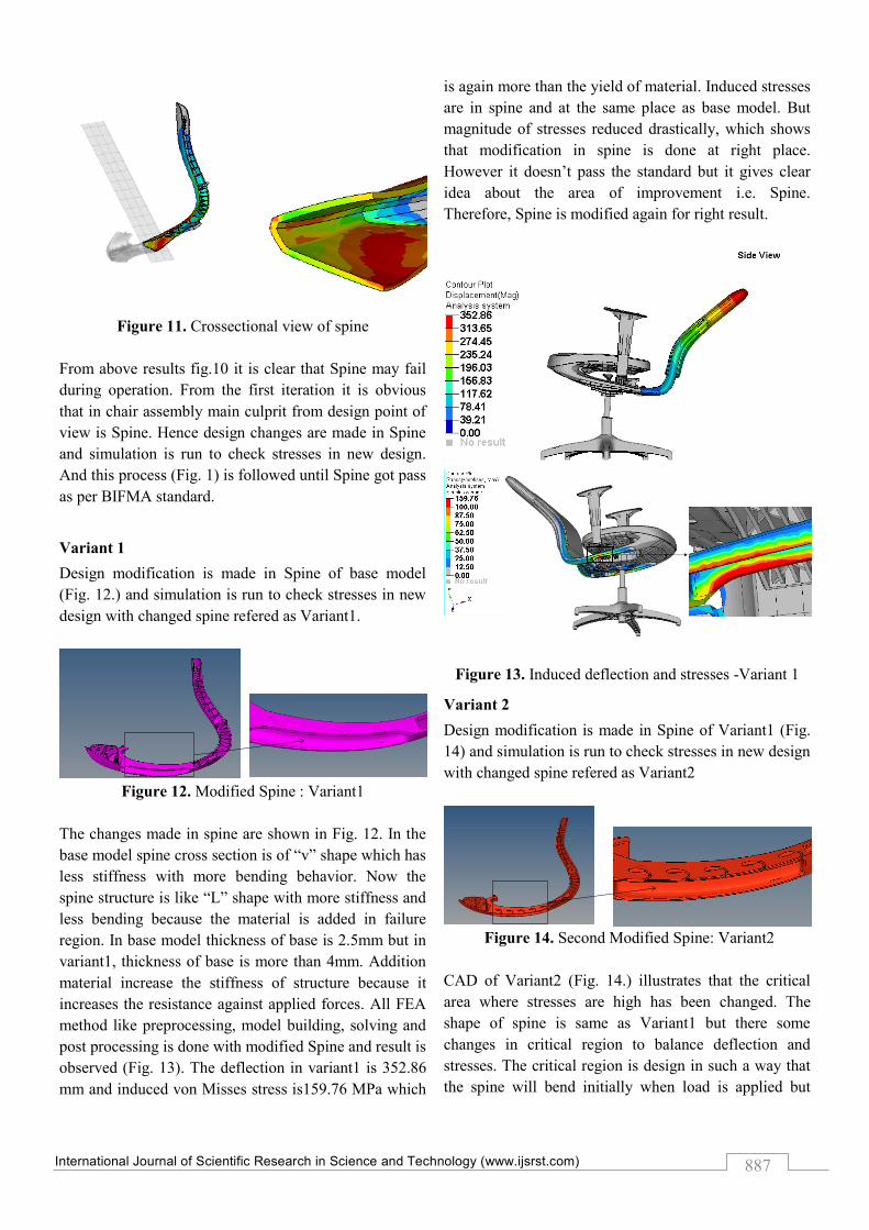
sectional view of Spine is shown in fig. 11. Given fig.11
shows there is changes at shown location. Chair may
break due to applied load. And hence chair does not
fullfill the BIFMA requirement. Hence, there is
modification in spine to reduce the von Misses stresses.
Figure 9. Force Vs time graph
Figure 10. Induced deflection and stresses due to
applied force (890N)
Zytel73G30HSLNC010
Zytel70G33LNC010
Polypropylene(PP)
Steel
International Journal of Scientific Research in Science and Technology (www.ijsrst.com)
887
Figure 11. Crossectional view of spine
From above results fig.10 it is clear that Spine may fail
during operation. From the first iteration it is obvious
that in chair assembly main culprit from design point of
view is Spine. Hence design changes are made in Spine
and simulation is run to check stresses in new design.
And this process (Fig. 1) is followed until Spine got pass
as per BIFMA standard.
Variant 1
Design modification is made in Spine of base model
(Fig. 12.) and simulation is run to check stresses in new
design with changed spine refered as Variant1.
Figure 12. Modified Spine : Variant1
The changes made in spine are shown in Fig. 12. In the
base model spine cross section is of “v” shape which has
less stiffness with more bending behavior. Now the
spine structure is like “L” shape with more stiffness and
less bending because the material is added in failure
region. In base model thickness of base is 2.5mm but in
variant1, thickness of base is more than 4mm. Addition
material increase the stiffness of structure because it
increases the resistance against applied forces. All FEA
method like preprocessing, model building, solving and
post processing is done with modified Spine and result is
observed (Fig. 13). The deflection in variant1 is 352.86
mm and induced von Misses stress is159.76 MPa which
is again more than the yield of material. Induced stresses
are in spine and at the same place as base model. But
magnitude of stresses reduced drastically, which shows
that modification in spine is done at right place.
However it doesn‟t pass the standard but it gives clear
idea about the area of improvement i.e. Spine.
Therefore, Spine is modified again for right result.
Figure 13. Induced deflection and stresses -Variant 1
Variant 2
Design modification is made in Spine of Variant1 (Fig.
14) and simulation is run to check stresses in new design
with changed spine refered as Variant2
Figure 14. Second Modified Spine: Variant2
CAD of Variant2 (Fig. 14.) illustrates that the critical
area where stresses are high has been changed. The
shape of spine is same as Variant1 but there some
changes in critical region to balance deflection and
stresses. The critical region is design in such a way that
the spine will bend initially when load is applied but

International Journal of Scientific Research in Science and Technology (www.ijsrst.com)
888
after 5mm of deflection their teeth which are going to
lock with base of Spine and resist further bending. These
teeth are thicker than base and provides good stiffness in
this region which is critical. Due to these extra thick
teeth the Spine becomes much stiffer than base model
and variant1 and hence gives better result than Base
Model and Variant1.
Figure 15. Induced deflection and Stresses-Variant 2
Deflection due to applied load in Variant2 is 381.67mm
and von Misses stress is129.98 MPa. Induced stress is
less than the yield of material and the chair may pass the
BIFMA standard in case of Variant2.
FIG. 16. COMPARATIVE ANALYSIS OF BASE
MODEL, VARIANT1 AND VARIANT2
The comparative analysis of Base model, Variant1 and
Variant 2 depicts the improvement in the stresses w.r.t.
design modification (Fig. 16). Final modification –
Variant2 satisfies the BIFMA standard. Further, the
generated model is subjected to the experimental testing
and the results are validated. Due to data confidentiality
policies of project funding bodies, the experimental test
results are not presented here.
IV. CONCLUSION
BIFMA standard is used to design the office chair and it
is validated using FEA tools. The methodology
consisted of Pre-processing using Hypermesh, analysis
using LS-Dyna, and post-processing using Hyperview.
Upon iterative modifications and validations, a final
chair-model satisfying the BIFMA standard is obtained.
The final model generation mainly involved Spine
concentric modification and analysis. Prototype of final
model is manufactured and experimental testing is done
by funding bodies. However, experimental testing is
beyond the scope of this study. FEA results and
experimental results are compared and it showed close
approximation with each other. Further, minor changes
are made in spine to improve results after experimental
testing.
V. ACKNOWLEDGMENT
First Author want to thanks Wissen Baum Engineering
Solutions LLP., Pune, for providing the necessary
financial support, infrastructure to carry out this research
work and facilitating the experimental testing of the
design model. I thanks to Shree Ramchandra College of

International Journal of Scientific Research in Science and Technology (www.ijsrst.com)
889
Engineering, Pune to provide necessary facilities to
carry out this research work.
VI. REFERENCES
[1]. Bellingar, T.A., Benden, M.E., New
ANSI/BIFMA Standard for Testing of Educational
Seating. Ergon.Des. Q. Hum. Factors Appl., 2015,
23, pp. 23-27.
[2]. Springer, T., The future of ergonomic office
seating. Knoll Workplace Res., 2010.
[3]. Zhang, J., Mason, M., Hodgson, A., Guo, B., et
al., An inter-laboratory comparison study of the
ANSI/BIFMA standard test method M7. 1 for
furniture, in: Proceedings of the 9th International
Healthy Buildings Conference and Exhibition,
2009, pp. 13-17.
[4]. XIONG, Z., LUO, H., Preprocessing technology
of FEA based on HyperMesh software J. Drain.
Irrig. Mach., 2006, 3, pp. 009.
[5]. Gantner, P., Bauer, H., Harrison, D.K., De Silva,
A.K., FEA-simulation of bending processes with
LS-DYNA, in: Proceedings of 8th International
LS-Dyna Users Conference, Troy, MI, USA,
2004.
[6]. Kurowski, P.M., Finite element analysis for
design engineers, SAE Technical Paper, 2004.
[7]. Dar, F.H., Meakin, J.R., Aspden, R.M., Statistical
methods in finite element analysis. J. Biomech.,
2002, 35, pp. 1155-1161.
[8]. Mao, K.M., Sun, C.T., A refined global-local
finite element analysis method. Int. J. Numer.
Methods Eng., 1991, 32, pp. 29-43.
[9]. Citipitioglu, E., Nicolas, V.T., Tolani, S.K., Finite
element method in stress analysis practice, SAE
Technical Paper, 1977.
[10]. Eckelman, C.A., Erdil, Y.Z., Performance Test
Method for Intensive Use Chairs-FNEW 83-269:
A Description of the Test Method with Drawings.
n.d.


![BIFMA ASEAN Model - Okamura · 2021. 1. 18. · BIFMA ASEAN Model Issued March 2020 [ BIFMA(㎜)[ EN StandardStandard ] Issued December 2020. Color options for Flame Polished](https://static.fdocuments.in/doc/165x107/610a665e56c574660d2d27c8/bifma-asean-model-okamura-2021-1-18-bifma-asean-model-issued-march-2020-.jpg)