
Valet Amplifiervaletamplifiers.com/Valet_Manual.pdf · VALET AMPLIFIER INSTALLATION USER MANUAL...
18
Installation Manual Valet Amplifier
Transcript of Valet Amplifiervaletamplifiers.com/Valet_Manual.pdf · VALET AMPLIFIER INSTALLATION USER MANUAL...
V A L E T A M P L I F I E R I N S TA L L AT I O N U S E R M A N U A L
Installation Manual
Valet Amplifier
V A L E T A M P L I F I E R I N S TA L L AT I O N U S E R M A N U A L
Table of Contents
Product Description 3
Specifications 3
Included in package 3
Safety Instructions 4
8 Channel Amplifier Collection 5
Echo Dot Connection 6
Echo Dot Installation 7
External Sources 9
12V Trigger 9
Basic Operation 7
Trouble Shooting 8
V A L E T A M P L I F I E R I N S TA L L AT I O N U S E R M A N U A L
Thank you for purchasing the Valet amplifier. At Origin Acoustics, we take pride
in providing you with a high quality product. All of Origin Acoustics’ products are
designed to have excellent sound quality, longevity, and a simple installation
process.
This instruction booklet covers the necessary information for a smooth
installation, including: the tools you will need, step-by-step instructions for
installation, troubleshooting tips for any errors that may occur, and all warranty
information. If for any reason you experience problems or if you have installation
questions please call us at (844) 674-4461. Hours of operation are 8:00am to
5:00pm (Pacific Time), Monday through Friday.
V A L E T A M P L I F I E R I N S TA L L AT I O N U S E R M A N U A L
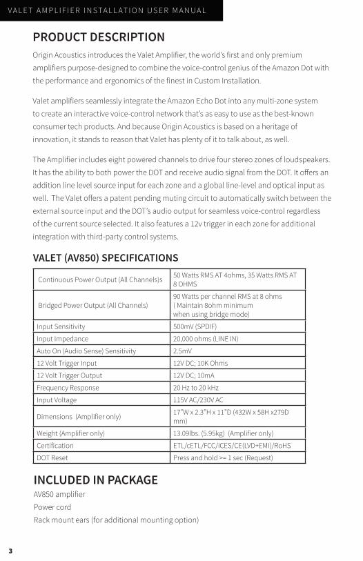
PRODUCT DESCRIPTIONOrigin Acoustics introduces the Valet Amplifier, the world’s first and only premium
amplifiers purpose-designed to combine the voice-control genius of the Amazon Dot with
the performance and ergonomics of the finest in Custom Installation.
Valet amplifiers seamlessly integrate the Amazon Echo Dot into any multi-zone system
to create an interactive voice-control network that’s as easy to use as the best-known
consumer tech products. And because Origin Acoustics is based on a heritage of
innovation, it stands to reason that Valet has plenty of it to talk about, as well.
The Amplifier includes eight powered channels to drive four stereo zones of loudspeakers.
It has the ability to both power the DOT and receive audio signal from the DOT. It offers an
addition line level source input for each zone and a global line-level and optical input as
well. The Valet offers a patent pending muting circuit to automatically switch between the
external source input and the DOT’s audio output for seamless voice-control regardless
of the current source selected. It also features a 12v trigger in each zone for additional
integration with third-party control systems.
VALET (AV850) SPECIFICATIONS
Continuous Power Output (All Channels)s 50 Watts RMS AT 4ohms, 35 Watts RMS AT 8 OHMS
Bridged Power Output (All Channels)90 Watts per channel RMS at 8 ohms ( Maintain 8ohm minimum when using bridge mode)
Input Sensitivity 500mV (SPDIF)
Input Impedance 20,000 ohms (LINE IN)
Auto On (Audio Sense) Sensitivity 2.5mV
12 Volt Trigger Input 12V DC; 10K Ohms
12 Volt Trigger Output 12V DC; 10mA
Frequency Response 20 Hz to 20 kHz
Input Voltage 115V AC/230V AC
Dimensions (Amplifier only) 17”W x 2.3”H x 11”D (432W x 58H x279D mm)
Weight (Amplifier only) 13.09lbs. (5.95kg) (Amplifier only)
Certification ETL/cETL/FCC/ICES/CE(LVD+EMI)/RoHS
DOT Reset Press and hold >= 1 sec (Request)
3
INCLUDED IN PACKAGEAV850 amplifier
Power cord
Rack mount ears (for additional mounting option)
V A L E T A M P L I F I E R I N S TA L L AT I O N U S E R M A N U A L
4
ZONE
1
ZONE
2
ZONE
3
ZONE
4
1 2 3 4 5 6 7 8
FUSE TYPE:
T6.3AL 250V FOR 115V
T3.15AL 250V FOR 230V
50/60Hz 530W115/230V
SPEAKER SPEAKER SPEAKER SPEAKER
ZONE
1
LINE OUT
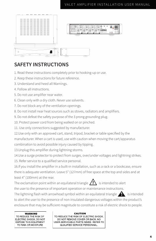
SAFETY INSTRUCTIONS1. Read these instructions completely prior to hooking-up or use.
2. Keep these instructions for future reference.
3. Understand and heed all Warnings.
4. Follow all instructions.
5. Do not use amplifier near water.
6. Clean only with a dry cloth. Never use solvents.
7. Do not block any of the ventilation openings.
8. Do not install near heat sources such as stoves, radiators and amplifiers.
9. Do not defeat the safety purpose of the 3 prong grounding plug.
10. Protect power cord from being walked on or pinched.
11. Use only connections suggested by manufacturer.
12.Use only with an approved cart, stand, tripod, bracket or table specified by the
manufacturer. When a cart is used, use with caution when moving the cart/apparatus
combination to avoid possible injury caused by tipping.
13.Unplug this amplifier during lightning storms.
14.Use a surge protector to protect from surges, over/under voltages and lightning strikes.
15. Refer service to a qualified service personal.
16.If you install the amplifier in a built-in installation, such as a rack or a bookcase, ensure
there is adequate ventilation. Leave 5” (127mm) of free space at the top and sides and at
least 4” (100mm) at the rear.
The exclamation point within an equilateral triangle is intended to alert
the user to the presence of important operation or maintenance instructions.
The lightning flash with arrowhead symbol within an equilateral triangle is intended
to alert the user to the presence of non-insulated dangerous voltages within the product’s
enclosure that may be sufficient magnitude to constitute a risk of electric shock to people.
V A L E T A M P L I F I E R I N S TA L L AT I O N U S E R M A N U A L
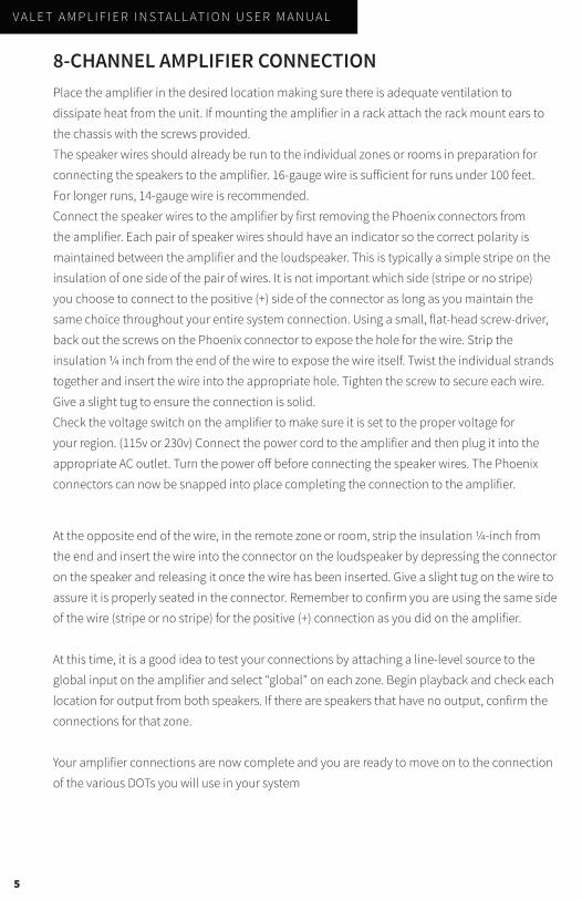
8-CHANNEL AMPLIFIER CONNECTIONPlace the amplifier in the desired location making sure there is adequate ventilation to
dissipate heat from the unit. If mounting the amplifier in a rack attach the rack mount ears to
the chassis with the screws provided.
The speaker wires should already be run to the individual zones or rooms in preparation for
connecting the speakers to the amplifier. 16-gauge wire is sufficient for runs under 100 feet.
For longer runs, 14-gauge wire is recommended.
Connect the speaker wires to the amplifier by first removing the Phoenix connectors from
the amplifier. Each pair of speaker wires should have an indicator so the correct polarity is
maintained between the amplifier and the loudspeaker. This is typically a simple stripe on the
insulation of one side of the pair of wires. It is not important which side (stripe or no stripe)
you choose to connect to the positive (+) side of the connector as long as you maintain the
same choice throughout your entire system connection. Using a small, flat-head screw-driver,
back out the screws on the Phoenix connector to expose the hole for the wire. Strip the
insulation ¼ inch from the end of the wire to expose the wire itself. Twist the individual strands
together and insert the wire into the appropriate hole. Tighten the screw to secure each wire.
Give a slight tug to ensure the connection is solid.
Check the voltage switch on the amplifier to make sure it is set to the proper voltage for
your region. (115v or 230v) Connect the power cord to the amplifier and then plug it into the
appropriate AC outlet. Turn the power off before connecting the speaker wires. The Phoenix
connectors can now be snapped into place completing the connection to the amplifier.
At the opposite end of the wire, in the remote zone or room, strip the insulation ¼-inch from
the end and insert the wire into the connector on the loudspeaker by depressing the connector
on the speaker and releasing it once the wire has been inserted. Give a slight tug on the wire to
assure it is properly seated in the connector. Remember to confirm you are using the same side
of the wire (stripe or no stripe) for the positive (+) connection as you did on the amplifier.
At this time, it is a good idea to test your connections by attaching a line-level source to the
global input on the amplifier and select “global” on each zone. Begin playback and check each
location for output from both speakers. If there are speakers that have no output, confirm the
connections for that zone.
Your amplifier connections are now complete and you are ready to move on to the connection
of the various DOTs you will use in your system
5
V A L E T A M P L I F I E R I N S TA L L AT I O N U S E R M A N U A L
6
Echo DOT ConnectionOne of the great advantages of the Valet amplifier is how simple it is to connect the Echo
DOT in each zone. A simple CAT6 cable is all that is needed to make both the power
and signal connections. Although CAT5 cable would be adequate in the majority of
applications, CAT6 is recommended.
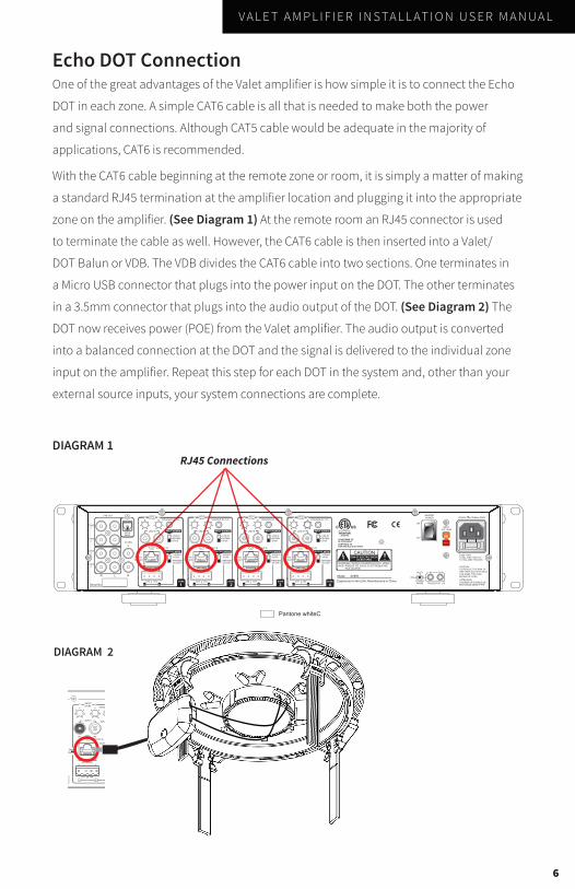
With the CAT6 cable beginning at the remote zone or room, it is simply a matter of making
a standard RJ45 termination at the amplifier location and plugging it into the appropriate
zone on the amplifier. (See Diagram 1) At the remote room an RJ45 connector is used
to terminate the cable as well. However, the CAT6 cable is then inserted into a Valet/
DOT Balun or VDB. The VDB divides the CAT6 cable into two sections. One terminates in
a Micro USB connector that plugs into the power input on the DOT. The other terminates
in a 3.5mm connector that plugs into the audio output of the DOT. (See Diagram 2) The
DOT now receives power (POE) from the Valet amplifier. The audio output is converted
into a balanced connection at the DOT and the signal is delivered to the individual zone
input on the amplifier. Repeat this step for each DOT in the system and, other than your
external source inputs, your system connections are complete.
DIAGRAM 1
DIAGRAM 2
RJ45 Connections
ZONE
1
ZONE
2
ZONE
3
ZONE
4
1 2 3 4 5 6 7 8
FUSE TYPE:
T6.3AL 250V FOR 115V
T3.15AL 250V FOR 230V
50/60Hz 530W115/230V
SPEAKER SPEAKER SPEAKER SPEAKER
ZONE
1
LINE OUT
V A L E T A M P L I F I E R I N S TA L L AT I O N U S E R M A N U A L
Echo DOT InstallationOne of the most important features of the Valet amplifier is the available option to mount the
DOT in the remote room so it blends into the environment. The ceiling mount option takes
advantage of the same Tool-Less Mounting System used in the installation of our Director
in-ceiling speakers.
Determine the desired location, keeping in mind the requirement for the DOT to be in a position
to “hear” your voice commands. In retrofit applications use a stud finder to determine the
position of the ceiling joists before cutting the hole. There are two size options, one for our
5-inch ceiling grille and one for our 6/8-inch ceiling grille. The cutout size for the 5-inch mount is
5 7/8 – inches in diameter. The cutout size for the 6/8-inch size is 8 3/4 - inches in diameter.
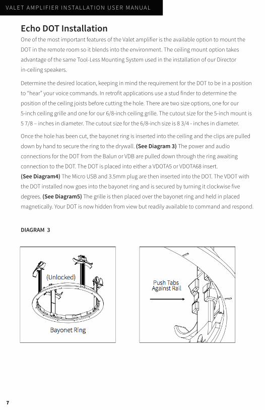
Once the hole has been cut, the bayonet ring is inserted into the ceiling and the clips are pulled
down by hand to secure the ring to the drywall. (See Diagram 3) The power and audio
connections for the DOT from the Balun or VDB are pulled down through the ring awaiting
connection to the DOT. The DOT is placed into either a VDOTA5 or VDOTA68 insert.
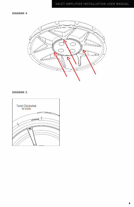
(See Diagram4) The Micro USB and 3.5mm plug are then inserted into the DOT. The VDOT with
the DOT installed now goes into the bayonet ring and is secured by turning it clockwise five
degrees. (See Diagram5) The grille is then placed over the bayonet ring and held in placed
magnetically. Your DOT is now hidden from view but readily available to command and respond.
7
DIAGRAM 3
V A L E T A M P L I F I E R I N S TA L L AT I O N U S E R M A N U A L
DIAGRAM 4
DIAGRAM 5
8
V A L E T A M P L I F I E R I N S TA L L AT I O N U S E R M A N U A L
Connecting External SourcesAny third-party source with a line level input can be connected to the Valet amplifier via the
onboard RCA connections. These can be zone specific or global as required. Zone specific
inputs can only be played back in a single zone while global inputs can be accessed by every
zone. Small switches below the RCA connections in each zone can be used to select Line
In (Zone Specific) Global (From the Global Input) or SPDIF. SPDIF is a global digital optical
connection that takes advantage of the amplifier’s onboard digital-to-analog converter or
DAC. Again, this is a global connection and can be accessed by every zone.
12v TriggerEach zone offers a 12v trigger that is activated whenever Alexa is addressed and remains
active until the command/response has been completed. This trigger can be used to
interface with any external control or automation system that accepts a 12v trigger
interface.
9
There is also an input gain control for each channel at the top of the individual zone sections.
This allows for a max volume to be set for each zone.
As mentioned, the Valet amplifier features an auto-muting circuit (Patent pending auto-muting
circuit) that mutes the external source when Alexa is addressed and remains muted until
whatever action that has been requested is completed. If Alexa is asked to play music from
one of the various streaming services available on the DOT, this musical content overrides the
external source until Alexa is asked to stop that musical playback.
V A L E T A M P L I F I E R I N S TA L L AT I O N U S E R M A N U A L
Basic OperationThe Valet amplifier is an integral part of your multi-room audio distribution system and
can be expanded to control many aspects of the home through “Skills” found in the Echo
DOT protocol. However, for the most part, the Valet will be seamless and automatic in
its operation. Voice commands given to the DOT will be processed and responses will be
acknowledged through the speakers in the room. Music from the DOT’s streaming sources
will be accessed as requested and also be played back through the system’s speakers.
External sources will be played back globally or zone specifically based on the system setup.
The DOT will override and mute these sources as needed.
As you expand the DOT’s capabilities through adding various skills you will be able to
control other systems such as lighting and thermostats and Alexa will make you aware of
her response to these commands through the loudspeakers in each zone. As the DOT’s
capabilities continue to grow and develop, your Valet amplifier will continue to provide both
musical and voice response fidelity that will substantially enhance your listening experience.
10
V A L E T A M P L I F I E R I N S TA L L AT I O N U S E R M A N U A L
If possible, it’s often good to try to isolate the problem first. For example, if you’re playing
a DVD on a television and there’s no sound, try connecting an MP3 player to the system to
see if that works. If it does work, then the problem is with the television, DVD player, or the
cables connecting them. If it doesn’t work, the problem will be with the amplifier, speakers,
or those cables.
Troubleshooting
Problem Possible Cause
No Sound The volume may be turned down or muted. Check the volume settings on both the amplifier and the television/computer/CD player/etc.
No Sound Make sure the proper source is selected on the amplifier or receiver.
No Sound Check the cord connecting the amplifier with the source. The cord may be damaged or plugged into the wrong input or output.
No Sound Check the wires connecting the amplifier with the speakers. Make sure they’re connected properly and not damaged in any way.
Poor Sound Quality
If you hear something like static, or the sound is cutting in and out, check the audio cables. If the problem increases when a cable is being moved, then the cable is most likely faulty or not connected properly.
Poor Sound Quality
Today’s audio systems may have several places to adjust the volume, for example your MP3 player may have a volume control, and your amplifier may also have one. Check to be certain that the volume isn’t turned up past 80% on any device.
Poor Sound Quality
Try changing sources to be certain that the selection you’ve chosen is a good quality recording.
11
V A L E T A M P L I F I E R I N S TA L L AT I O N U S E R M A N U A L
If you have any questions or concerns about installing or using this product, you can reach
us through one of the following methods:
Phone: (844) 674-4461
Hours of operation: 8:00am - 5:00pm (Pacific Time), Mon - Fri
Email: [email protected]
If you are having technical trouble, please include the model number and briefly explain
what steps you took to resolve the problem in your email, or be prepared to answer these
questions over the phone. If you are considering returning the product, it’s required that
you contact Origin Acoustics prior to any return attempts. This way we can determine
if the issue can be resolved without returning the product, or if needed we can provide
instructions and support for the return process.
Technical Assistance
12
V A L E T A M P L I F I E R I N S TA L L AT I O N U S E R M A N U A L
Origin Acoustics warrants to the original retail purchaser only that this Origin
Acoustics product will be free from defects in materials and workmanship,
provided the speaker was purchased from an Origin Acoustics authorized dealer.
If the product is determined to be defective, it will be repaired or replaced at
Origin Acoustics’ discretion. If the product must be replaced yet it is no longer
manufactured, it will be replaced with a model of equal to or greater value that
is the most similar to the original. If this is the case, installing the replacement
model may require mounting modifications; Origin Acoustics will not be
responsible for any such related costs.
Limited Lifetime Warranty
13
V A L E T A M P L I F I E R I N S TA L L AT I O N U S E R M A N U A L
• Accidental damage
• Damage caused by abuse or misuse
• Damage caused by attempted repairs/modifications by anyone other than Origin Acoustics or an authorized dealer
• Damage caused by improper installation
• Normal wear, maintenance, and environmental issues
• Damage caused by voltage inputs in excess of the rated maximum of the unit
• Damage inflicted during the return shipment
Not Covered by Warranty
14
V A L E T A M P L I F I E R I N S TA L L AT I O N U S E R M A N U A L
This warranty may not be valid if the product was purchased through an
unauthorized dealer. This warranty only applies to the individual that made the
original purchase, and it cannot be applied to other purchases. The purchaser
must be prepared to provide proof of purchase (receipt). This warranty will not
be valid if the identifying number or serial number has been removed, defaced,
or altered.
Requirements & Warranty Coverage
15

V A L E T A M P L I F I E R I N S TA L L AT I O N U S E R M A N U A L
Before making any return attempts, it is required that you first contact Origin
Acoustics. Return product to Origin Acoustics or your dealer, either in person or by
mail. It’s preferable if the product is returned in the original packaging. If this isn’t
possible, the customer is responsible for insuring the shipment for the full value of
the product.
This warranty is in lieu of all other expressed or implied warranties. Some states do
not allow limitations on implied warranties, so this may not apply depending on
the customer’s location. (For more information, see Magnuson-Moss Warranty Act.)
Return Process
16

6975 S. Decatur Blvd, Las Vegas, NV 89147• www.originacoustics.com • 844-674-4461
©2017 Origin Acoustics. All copyrighted, trademarked and patented elements mentioned herein are the sole property of Origin Acoustics.