Vaisala Indigo 201 Analog Output Transmitter …...Indigo, and no configuration has been set...
52
EN ES JA ZH M211876EN-F Quick Guide Analog Output Transmitter Indigo 201
Transcript of Vaisala Indigo 201 Analog Output Transmitter …...Indigo, and no configuration has been set...
EN
ES
JA
ZH
M211876EN-F
Quick GuideAnalog Output Transmitter
Indigo 201

PUBLISHED BY
Vaisala Oyj
Vanha Nurmijärventie 21, FI-01670 Vantaa, Finland
P.O. Box 26, FI-00421 Helsinki, Finland
+358 9 8949 1
Visit our Internet pages at www.vaisala.com.
No part of this manual may be reproduced,published or publicly displayed in any form or byany means, electronic or mechanical (includingphotocopying), nor may its contents be modified,translated, adapted, sold or disclosed to a thirdparty without prior written permission of thecopyright holder. Translated manuals andtranslated portions of multilingual documents arebased on the original English versions. Inambiguous cases, the English versions areapplicable, not the translations.
The contents of this manual are subject to changewithout prior notice.
Local rules and regulations may vary and theyshall take precedence over the informationcontained in this manual. Vaisala makes norepresentations on this manual’s compliance withthe local rules and regulations applicable at anygiven time, and hereby disclaims any and allresponsibilities related thereto.
This manual does not create any legally bindingobligations for Vaisala towards customers or endusers. All legally binding obligations and
agreements are included exclusively in theapplicable supply contract or the GeneralConditions of Sale and General Conditions ofService of Vaisala.
This product contains software developed byVaisala or third parties. Use of the software isgoverned by license terms and conditionsincluded in the applicable supply contract or, inthe absence of separate license terms andconditions, by the General License Conditions ofVaisala Group.
This product may contain open source software(OSS) components. In the event this productcontains OSS components, then such OSS isgoverned by the terms and conditions of theapplicable OSS licenses, and you are bound by theterms and conditions of such licenses inconnection with your use and distribution of theOSS in this product. Applicable OSS licenses areincluded in the product itself or provided to youon any other applicable media, depending oneach individual product and the product itemsdelivered to you.

Table of Contents
English.................................................................................................................................5Español.............................................................................................................................. 15日本語...............................................................................................................................27中文...................................................................................................................................39
Table of Contents
3
EU Declaration of Conformity........................................................................................50

M211876EN-F
4

1 Indigo 201 Quick Guide
1.1 Introduction to Indigo Transmitters
1.35% | Carbon dioxide
WLAN is activated
Indigo 201
Figure 1 Indigo 201 With and Without Display, Wireless Interface Examples
Vaisala Indigo transmitters are a plug-and-play host device platform for Vaisala Indigo-compatible probes. Indigo transmitters extend the feature set of connected probes with arange of additional options for outputs, measurement viewing, status monitoring, andconfiguration interface access.
Depending on the Indigo model, a display is available as an optional selection or as astandard feature. In the non-display model, an LED indicator is used for notifications. Theconfiguration interface of Indigo transmitters is a browser-based wireless UI that requires amobile device or computer that supports wireless connectivity (IEEE 802.11 b/g/n WLAN).
1.1.1 Indigo 201 Basic Features and Options• All Vaisala Indigo-compatible probes can be connected to all Indigo transmitter models• Plug-and-play probe installation: when unconfigured, Indigo automatically adapts the
analog output configuration of the connected Indigo-compatible probe• Wireless configuration interface: connect to the scalable browser-based UI of Indigo
201 to change probe and transmitter settings, view measurements and review probeand transmitter status
• 3.5” TFT LCD color display or non-display model with LED indicator• Power supply input 15 ... 30 VDC (24 VAC +/-10% 50/60Hz)• 3 current (mA) or voltage (V) analog outputs• 2 configurable relays
Chapter – Indigo 201 Quick Guide
5
ENGLISH

1.2 Input and Output SpecificationTable 1 Inputs and Outputs
Property Specification
Analog outputs 3 voltage (V) or current (mA) outputs:
• 0 … 10 V / 0 … 5 V / 0 … 1 V / 1 … 5 V (min. load1kΩ)
• 0 … 20 mA / 4 … 20 mA (max. load 500 Ω)
Accuracy of analog outputs at 20 °C ± 0.1 % full scale
Relays 2 configurable relays (VAC/VDC)
Device maximum specification (resistive load):
• Max. switching power 30 W / 37.5 VA
UL-rated maximum specification (resistive load):
• AC: max. 28 V / 0.5 A• DC: max. 40 V / 0.24 A• Up to 30 VDC:
• max. switching current 1 A• max. switching power 30 W
Power supply input 1) 15 ... 30 VDC (24 VAC +/-10% 50/60Hz)
Maximum current Transmitter and connected probe max. 1 A
Power consumption Transmitter max. 3 W (+ connected probe, variesdepending on probe type)
Probe connector M12/5 connector for probe or probe cable connection(Vaisala Indigo-compatible probes)
Cable feed throughs 2 options: rubber lead-through on the bottom of thetransmitter, and opening with a seal at the back of thetransmitter
Screw terminal wire size 0.2 ... 1.5 mm2
1) Using a power supply with overload protection is recommended for electrical safety.
Do not modify the unit or use it in ways not described in the documentation.Improper modification may lead to safety hazards, equipment damage, failure toperform according to specification, or decreased equipment lifetime.
CAUTION!
M211876EN-F
6
1.3 Indigo Transmitter Parts
2
3
4
5
7
6
1
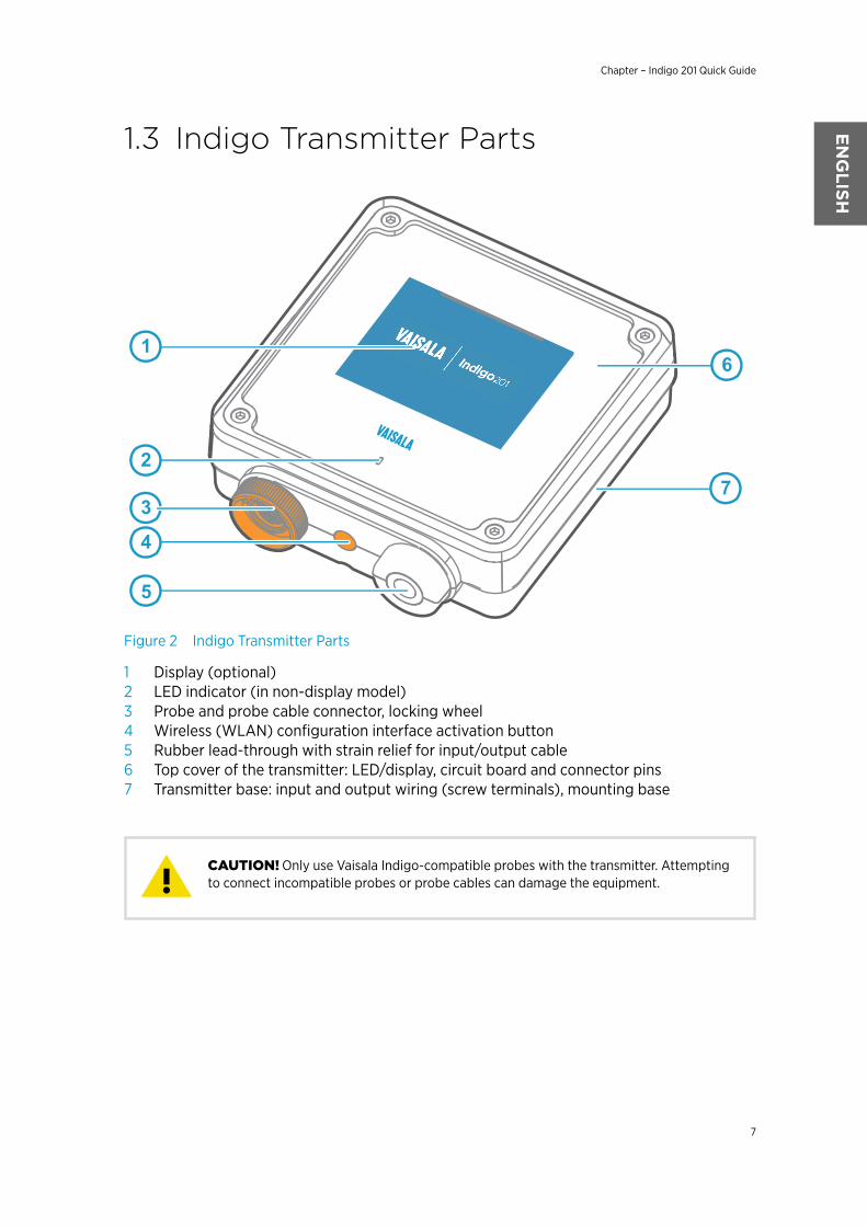
Figure 2 Indigo Transmitter Parts
1 Display (optional)2 LED indicator (in non-display model)3 Probe and probe cable connector, locking wheel4 Wireless (WLAN) configuration interface activation button5 Rubber lead-through with strain relief for input/output cable6 Top cover of the transmitter: LED/display, circuit board and connector pins7 Transmitter base: input and output wiring (screw terminals), mounting base
Only use Vaisala Indigo-compatible probes with the transmitter. Attemptingto connect incompatible probes or probe cables can damage the equipment.CAUTION!
Chapter – Indigo 201 Quick Guide
7
ENGLISH

1.4 Opening and Mounting
To avoid damaging the connector pins of the transmitter, pull thetransmitter cover off the base in a straight angle. Do not twist or bend.CAUTION!
1. Loosen the 4 screws on the transmitter cover.
2. Carefully open the transmitter cover part of the way from both sides so it is easier topull the cover off the base.
3. Pull the transmitter cover off the base in a straight angle. Do not twist or bend.
4. Place the transmitter base on the installation surface and mount it with 3 screws. Seethe screw positions in Figure 3 (page 9).
5. Lead the input/output cable inside the transmitter (see Wiring Options (page 10)). Ifyou are wiring through the lead-through on the bottom of the transmitter, test that thestrain relief works with your cable.
6. Connect the input/output cable's wiring to the screw terminals (see Indigo TransmitterBase (page 9)) and reattach the cover when done.
M211876EN-F
8

1.5 Indigo Transmitter Base
1 2 4
5
6
3
INDIGO 201 ANALOG
OUTPUT TRANSMITTER
Serial No. SX12345678
Figure 3 Indigo 201 Transmitter Base Main Parts and Screw Positions
1 Probe and probe cable connector inside the locking wheel2 Wireless (WLAN) configuration interface activation button3 Wiring from the back: cut open the seal4 Rubber cable lead-through with strain relief5 Screw terminals for analog outputs 1-3 and relays A and B6 Screw terminals for 24 V power supply input
Do not energize the power supply before the wiring has been connected.CAUTION!
Chapter – Indigo 201 Quick Guide
9
ENGLISH

1.6 Wiring OptionsYou can wire an input/output cable either through the opening on the back of thetransmitter, or through the rubber lead-through on the bottom of the transmitter.
1
2
Ø 7 ... 8 mm
Figure 4 Indigo Wiring Options
1 Wiring from the back: cut the seal open2 Wiring through the rubber lead-through on the bottom of the transmitter
1. To wire the input/output cable through the back of the transmitter:
a. Cut off as much of the seal as is needed to fit your cable through the opening.
b. Lead the cable through the opening and attach a strain relief as needed.
c. If you wire only through the back, plug or seal the lead-through on the bottom.
2. To wire the input/output cable through the rubber lead-through on the bottom:
a. Push the input/output cable through the lead-through.
b. The lead-through provides strain relief and holds the cable in place. Tightening is notrequired.
The recommended cable diameter for wiring through the rubber lead-through is7 ... 8 mm. If you use a different cable size, test that the strain relief works asintended.
M211876EN-F
10
1.7 Attaching Probes and Cables
1
2
3
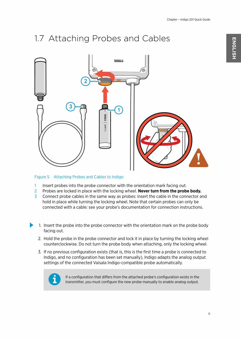
Figure 5 Attaching Probes and Cables to Indigo
1 Insert probes into the probe connector with the orientation mark facing out.2 Probes are locked in place with the locking wheel. Never turn from the probe body.3 Connect probe cables in the same way as probes: insert the cable in the connector and
hold in place while turning the locking wheel. Note that certain probes can only beconnected with a cable: see your probe's documentation for connection instructions.
1. Insert the probe into the probe connector with the orientation mark on the probe bodyfacing out.
2. Hold the probe in the probe connector and lock it in place by turning the locking wheelcounterclockwise. Do not turn the probe body when attaching, only the locking wheel.
3. If no previous configuration exists (that is, this is the first time a probe is connected toIndigo, and no configuration has been set manually), Indigo adapts the analog outputsettings of the connected Vaisala Indigo-compatible probe automatically.
If a configuration that differs from the attached probe's configuration exists in thetransmitter, you must configure the new probe manually to enable analog output.
Chapter – Indigo 201 Quick Guide
11
ENGLISH

1.8 Connecting to Wireless ConfigurationInterface
Select WLAN to connect to:
1. WLAN XYZ
3. WLAN ABC
2. Indigo_ID[xx]
1 3
500ppm
WLAN on
Indigo 200
2
Carbon dioxide concentration
Figure 6 Enabling and Accessing Indigo's Wireless Configuration Interface
1 Wireless connection activation button2 Wireless connection indicator (WLAN symbol) on the Indigo display3 Choose Indigo (Indigo_ID[xx]) from your wireless device's list of available connections
To connect to the wireless configuration interface:
1. Press the wireless connection activation button on the bottom of the transmitter.
2. When the wireless configuration interface becomes available, the Indigo display showsa connection notification. In the Indigo models with an LED indicator, the LED blinksgreen when the connection is active.
3. Open the wireless connection menu in your mobile device or computer and selectIndigo_ID[xx] (transmitter-specific SSID) from the list of available connections.
4. Depending on your device, the wireless configuration interface either launchesautomatically in your browser after you connect to Indigo, or you may need to startyour browser application manually.
5. When you open the Indigo interface in your browser, you are prompted to log in.
Only one device can be connected to the wireless configuration interface at a time.
For more information and troubleshooting instructions on accessing Indigo 201 wirelessconfiguration interface, see Indigo 201 User Guide.
M211876EN-F
12

1.9 Logging in to Wireless ConfigurationInterface
When you open Indigo's wireless configuration interface in your browser, you are promptedto log in. There are 2 available user levels:
• User: view-only access available for all users. Does not require a password.• Admin: password-protected access. To change settings, you must log in as admin.
Figure 7 Indigo Login View
To log in:
1. Enter the user name and password:
a. To log in as user (view-only access, no configuration rights), select User from theUser name dropdown. Leave the Password field empty.
b. To log in as admin (required for configuration), select Admin in the User namedropdown and type the admin password (default: 12345) in the Password field.
2. Select Log in after entering the login credentials. The wireless configuration interfaceopens in the Measurements view.
The user level (User or Admin) is shown in the upper right corner of all menu views.Select the user/admin icon in the upper right corner to change the user level.
Chapter – Indigo 201 Quick Guide
13
ENGLISH

1.10 Wireless Interface MenusIndigo transmitters are configured using a wireless browser-based configuration interface(requires a mobile device or computer with IEEE 802.11 b/g/n WLAN wireless connectivity).In addition to probe and transmitter configuration and calibration, you can also use thewireless interface to view measurement data and status information.
1
2
3
4
5
Figure 8 Wireless Configuration Interface, Desktop Browser View
1 Measurements: displays the measurement data of the connected probe2 Status: contains information about the status of Indigo and the connected probe (for
example, notifications and alarms)3 Calibration: calibrate and adjust probes using references. Available options (for
example, adjustment points) vary depending on the probe model.4 Settings: contains options for configuring the connection and display settings, outputs,
relays, probe-specific settings, and general device preferences
• General submenu: device information and general settings, wireless connectionand display settings
• Outputs submenu: configuration options for analog outputs 1-3• Relays submenu: settings for controlling relays A and B• Probe submenu: probe-specific settings such as environmental compensations
and filtering factor5 Main display area for menus and measurement information (desktop browser example)
You must be logged in as Admin to change settings with the wireless configurationinterface. Logging in as User gives view-only access.
M211876EN-F
14

1 Guía rápida Indigo 201
1.1 Introducción a Indigo
1.35% | Carbon dioxide
WLAN is activated
Indigo 201
Figura 9 Indigo 201 con y sin pantalla, ejemplos de interfaz inalámbrica
Los transmisores Vaisala Indigo son una plataforma de dispositivo host de instalaciónautomática para sondas compatibles con Vaisala Indigo. Los transmisores Indigo amplían elconjunto de características de las sondas conectadas con un rango de opciones adicionalespara salidas, visualización de mediciones, monitoreo del estado y acceso a la interfaz deconfiguración.
Según el modelo Indigo, una pantalla está disponible como selección opcional o comocaracterística estándar. En el modelo sin pantalla, se usa un indicador LED para lasnotificaciones. La interfaz de configuración de los transmisores Indigo es una interfaz deusuario inalámbrica basada en navegador que requiere un dispositivo móvil o unacomputadora que admita conectividad inalámbrica (IEEE 802.11 b/g/n WLAN).
1.1.1 Características y opciones básicas de Indigo 201• Todas las sondas compatibles con Vaisala Indigo se pueden conectar a todos los
modelos de transmisor Indigo• Instalación automática para sondas: cuando no está configurado, Indigo adapta
automáticamente la configuración de salida analógica de la sonda compatible conIndigo conectada
• Interfaz de configuración inalámbrica: conéctese a la interfaz de usuario escalablebasada en navegador de Indigo 201 para cambiar la configuración de la sonda y eltransmisor, ver las mediciones y revisar el estado de la sonda y el transmisor
• Pantalla a color TFT LCD de 3.5 " o modelo sin pantalla con indicador LED• Entrada del sistema de alimentación 15 a 30 VCC (24 VCA +/-10% 50/60Hz)
Capítulo – Guía rápida Indigo 201
15
ESPA
ÑOL

• 3 salidas analógicas de corriente (mA) o de voltaje (V)• 2 relés configurables
1.2 Especificación de entrada y salidaTabla 2 Entradas y salidas
Propiedad Especificación
Salidas analógicas 3 salidas de voltaje (V) o corriente (mA):
• 0 a 10 V/0 a 5 V/0 a 1 V/1 a 5 V (carga mínima 1 kΩ)• 0 a 20 mA/4 a 20 mA (carga máxima 500 Ω)
Precisión de salidas analógicas a 20 °C ±0,1 % escala completa
Relés 2 relés configurables (VCA/VCC)
Especificación máxima del dispositivo (carga resisti-va):
• Alimentación de conmutación máx. de 30 W/37,5VA
Especificación máxima de UL (carga resistiva):
• CA: máximo 28 V/0,5 A• CC: máximo 40 V/0,24 A• Hasta 30 VCC:
• corriente de conmutación máx. de 1 A• alimentación de conmutación máx. de 30 W
Entrada del suministro de energía 1) 15 ... 30 VCC (24 VCA +/-10% 50/60Hz)
Corriente máxima Transmisor y sonda conectados máx. de 1 A
Consumo de energía Transmisor máx. de 3 W (+ sonda conectada, varía se-gún el tipo de sonda)
Conector de la sonda Conector M12/5 para la sonda o el cable de conexiónde la sonda (sondas compatibles con Vaisala Indigo)
Cable de alimentación directa 2 opciones: paso de goma en la parte inferior deltransmisor y apertura con un sello en la parte poste-rior del transmisor
Tamaño del cable del terminal roscado 0.2 ... 1,5 mm2
1) Se recomienda el uso de un sistema de alimentación con protección de sobrecarga para la seguridad eléctrica.
No modifique la unidad y no la utilice de ninguna manera que no estédescripta en la documentación. Una modificación inadecuada puede provocar peligrosde seguridad, dañar el equipo, impedir el funcionamiento de acuerdo con laespecificación o reducir la duración del equipo.
PRECAUCIÓN
M211876EN-F
16

1.3 Piezas del transmisor Indigo
2
3
4
5
7
6
1
Figura 10 Piezas del transmisor Indigo
1 Pantalla (opcional)2 Indicador LED (en modelo sin pantalla)3 Conector del cable de sonda y sonda, rueda de bloqueo4 Botón de activación de la interfaz de configuración inalámbrica (WLAN)5 Conexión pasante de goma con pasamuros para cable de entrada/salida6 Cubierta superior del transmisor: LED/pantalla, placa de circuito y clavijas del conector7 Base del transmisor: cableado de entrada y salida (terminales de tornillo), base de
montaje
Solo use sondas compatibles con Vaisala Indigo con el transmisor.Intentar conectar sondas o cables de sonda incompatibles puede dañar el equipo.PRECAUCIÓN
Capítulo – Guía rápida Indigo 201
17
ESPA
ÑOL

1.4 Apertura y montaje
Para evitar dañar las clavijas del conector del transmisor, saque lacubierta del transmisor de la base en ángulo recto. No la doble ni tuerza.PRECAUCIÓN
1. Afloje los 4 tornillos en la cubierta del transmisor.
2. Abra con cuidado la pieza de la cubierta del transmisor de ambos lados para que seamás fácil retirar la cubierta de la base.
3. Retire la cubierta del transmisor de la base en ángulo recto. No la doble ni tuerza.
4. Coloque la base del transmisor en la superficie de instalación y móntela con 3 tornillos.Consulte las posiciones del tornillo en Figura 11 (página 19).
5. Pase el cable de entrada/salida dentro del transmisor (consulte Opciones de Cableado(página 20)). Si está pasando cables a través del conductor en la parte inferior deltransmisor, compruebe que el pasamuros funciona con su cable.
6. Conecte el cableado del cable de entrada/salida a los terminales de tornillo (consulteBase del transmisor de Indigo (página 19)) y vuelva a colocar la cubierta cuando hayaterminado.
M211876EN-F
18
1.5 Base del transmisor de Indigo
1 2 4
5
6
3
INDIGO 201 ANALOG
OUTPUT TRANSMITTER
Serial No. SX12345678
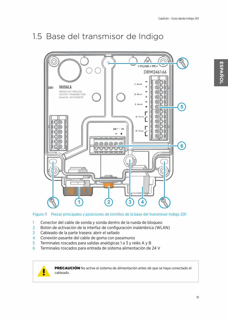
Figura 11 Piezas principales y posiciones de tornillos de la base del transmisor Indigo 201
1 Conector del cable de sonda y sonda dentro de la rueda de bloqueo2 Botón de activación de la interfaz de configuración inalámbrica (WLAN)3 Cableado de la parte trasera: abrir el sellado4 Conexión pasante del cable de goma con pasamuros5 Terminales roscados para salidas analógicas 1 a 3 y relés A y B6 Terminales roscados para entrada de sistema alimentación de 24 V
No active el sistema de alimentación antes de que se haya conectado elcableado.PRECAUCIÓN
Capítulo – Guía rápida Indigo 201
19
ESPA
ÑOL
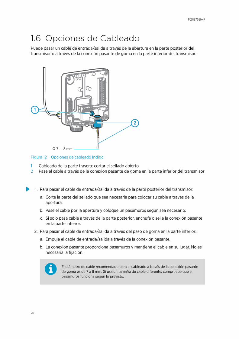
1.6 Opciones de CableadoPuede pasar un cable de entrada/salida a través de la abertura en la parte posterior deltransmisor o a través de la conexión pasante de goma en la parte inferior del transmisor.
1
2
Ø 7 ... 8 mm
Figura 12 Opciones de cableado Indigo
1 Cableado de la parte trasera: cortar el sellado abierto2 Pase el cable a través de la conexión pasante de goma en la parte inferior del transmisor
1. Para pasar el cable de entrada/salida a través de la parte posterior del transmisor:
a. Corte la parte del sellado que sea necesaria para colocar su cable a través de laapertura.
b. Pase el cable por la apertura y coloque un pasamuros según sea necesario.
c. Si solo pasa cable a través de la parte posterior, enchufe o selle la conexión pasanteen la parte inferior.
2. Para pasar el cable de entrada/salida a través del paso de goma en la parte inferior:
a. Empuje el cable de entrada/salida a través de la conexión pasante.
b. La conexión pasante proporciona pasamuros y mantiene el cable en su lugar. No esnecesaria la fijación.
El diámetro de cable recomendado para el cableado a través de la conexión pasantede goma es de 7 a 8 mm. Si usa un tamaño de cable diferente, compruebe que elpasamuros funciona según lo previsto.
M211876EN-F
20

1.7 Fijación de sondas y cables
1
2
3
Figura 13 Fijación de sondas y cables a Indigo
1 Inserte las sondas en el conector de la sonda con la marca de orientación hacia afuera.2 Las sondas se bloquean en su lugar con la rueda de fijación. Nunca gire desde el cuerpo
de la sonda.3 Conecte los cables de la sonda del mismo modo que las sondas: inserte el cable en el
conector y sosténgalo en su lugar mientras gira la rueda de bloqueo. Tenga en cuentaque algunas sondas se pueden conectar solo con un cable: consulte la documentaciónde su sonda para obtener instrucciones de conexión.
1. Inserte la sonda en el conector de la sonda con la marca de orientación en el cuerpo dela sonda hacia afuera.
2. Sostenga la sonda en el conector de la sonda y asegúrela en su lugar girando la ruedade bloqueo en el sentido contrario a las agujas del reloj. No gire el cuerpo de la sonda alcolocarla, hágalo solo con la rueda de bloqueo del transmisor.
Capítulo – Guía rápida Indigo 201
21
ESPA
ÑOL
3. Si no existe una configuración previa (es decir, esta es la primera vez que se conectauna sonda a Indigo y no se ha configurado manualmente), Indigo adaptaautomáticamente la configuración de salida analógica de la sonda compatible conVaisala Indigo conectada.
Si en el transmisor existe una configuración diferente a la de la sonda adjunta, debeconfigurar la nueva sonda manualmente para habilitar la salida analógica.
1.8 Conexión a la interfaz de configura-ción inalámbrica
Select WLAN to connect to:
1. WLAN XYZ
3. WLAN ABC
2. Indigo_ID[xx]
1 3
500ppm
WLAN on
Indigo 200
2
Carbon dioxide concentration
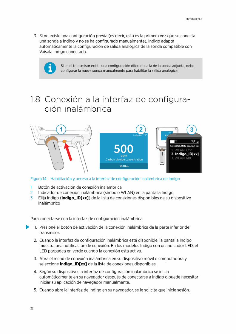
Figura 14 Habilitación y acceso a la interfaz de configuración inalámbrica de Indigo
1 Botón de activación de conexión inalámbrica2 Indicador de conexión inalámbrica (símbolo WLAN) en la pantalla Indigo3 Elija Indigo (Indigo_ID[xx]) de la lista de conexiones disponibles de su dispositivo
inalámbrico
Para conectarse con la interfaz de configuración inalámbrica:
1. Presione el botón de activación de la conexión inalámbrica de la parte inferior deltransmisor.
2. Cuando la interfaz de configuración inalámbrica está disponible, la pantalla Indigomuestra una notificación de conexión. En los modelos Indigo con un indicador LED, elLED parpadea en verde cuando la conexión está activa.
3. Abra el menú de conexión inalámbrica en su dispositivo móvil o computadora yseleccione Indigo_ID[xx] de la lista de conexiones disponibles.
4. Según su dispositivo, la interfaz de configuración inalámbrica se iniciaautomáticamente en su navegador después de conectarse a Indigo o puede necesitariniciar su aplicación de navegador manualmente.
5. Cuando abre la interfaz de Indigo en su navegador, se le solicita que inicie sesión.
M211876EN-F
22
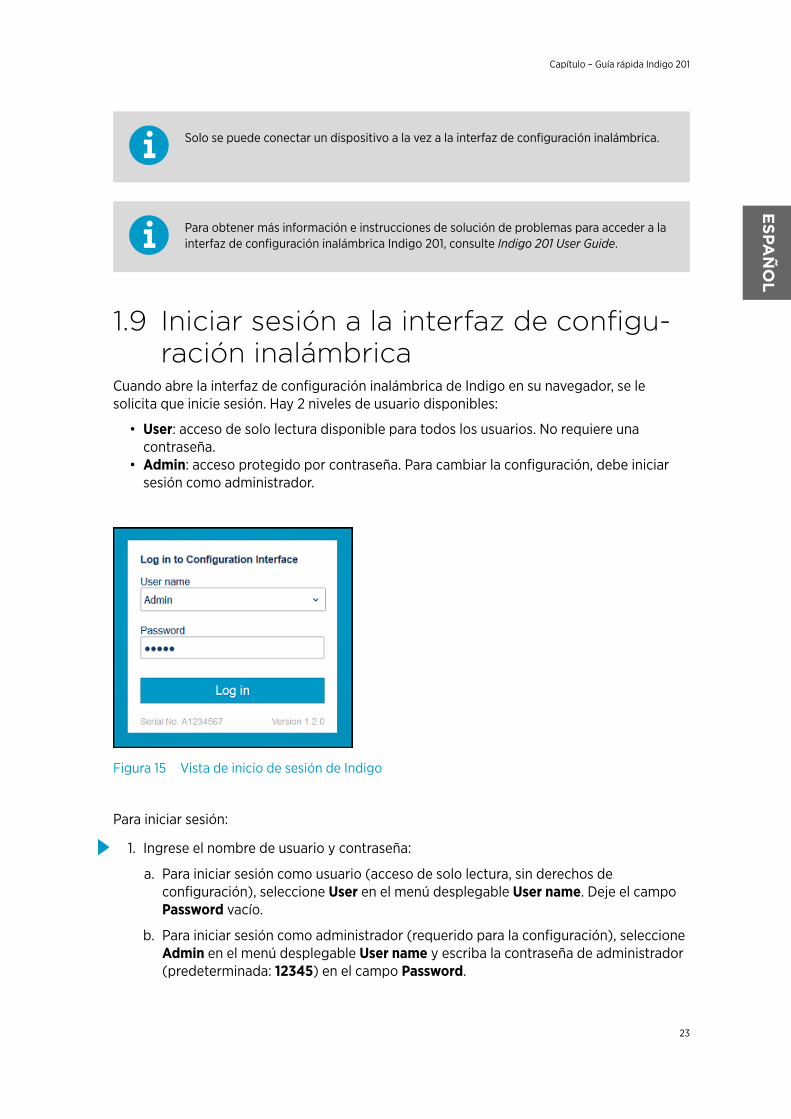
Solo se puede conectar un dispositivo a la vez a la interfaz de configuración inalámbrica.
Para obtener más información e instrucciones de solución de problemas para acceder a lainterfaz de configuración inalámbrica Indigo 201, consulte Indigo 201 User Guide.
1.9 Iniciar sesión a la interfaz de configu-ración inalámbrica
Cuando abre la interfaz de configuración inalámbrica de Indigo en su navegador, se lesolicita que inicie sesión. Hay 2 niveles de usuario disponibles:
• User: acceso de solo lectura disponible para todos los usuarios. No requiere unacontraseña.
• Admin: acceso protegido por contraseña. Para cambiar la configuración, debe iniciarsesión como administrador.
Figura 15 Vista de inicio de sesión de Indigo
Para iniciar sesión:
1. Ingrese el nombre de usuario y contraseña:
a. Para iniciar sesión como usuario (acceso de solo lectura, sin derechos deconfiguración), seleccione User en el menú desplegable User name. Deje el campoPassword vacío.
b. Para iniciar sesión como administrador (requerido para la configuración), seleccioneAdmin en el menú desplegable User name y escriba la contraseña de administrador(predeterminada: 12345) en el campo Password.
Capítulo – Guía rápida Indigo 201
23
ESPA
ÑOL
2. Seleccione Log in después de ingresar las credenciales de inicio de sesión. La interfazde configuración inalámbrica se inicia en la vista Measurements.
El nivel de usuario (User o Admin) se muestra en la esquina superior derecha detodas las vistas del menú.Seleccione el icono de usuario/administrador en la esquina superior derecha paracambiar el nivel de usuario.
1.10 Menús de interfaz inalámbricosLos transmisores Indigo se configuran mediante una interfaz de configuración inalámbricabasada en navegador (requiere un dispositivo móvil o una computadora con conectividadinalámbrica WLAN IEEE 802.11 b/g/n). Además de la configuración y calibración de la sonday el transmisor, también puede usar la interfaz inalámbrica para ver los datos de medición yla información de estado.
M211876EN-F
24
1
2
3
4
5
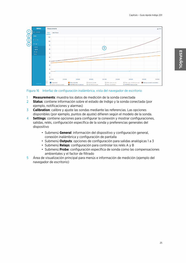
Figura 16 Interfaz de configuración inalámbrica, vista del navegador de escritorio
1 Measurements: muestra los datos de medición de la sonda conectada2 Status: contiene información sobre el estado de Indigo y la sonda conectada (por
ejemplo, notificaciones y alarmas)3 Calibration: calibre y ajuste las sondas mediante las referencias. Las opciones
disponibles (por ejemplo, puntos de ajuste) difieren según el modelo de la sonda.4 Settings: contiene opciones para configurar la conexión y mostrar configuraciones,
salidas, relés, configuración específica de la sonda y preferencias generales deldispositivo
• Submenú General: información del dispositivo y configuración general,conexión inalámbrica y configuración de pantalla
• Submenú Outputs: opciones de configuración para salidas analógicas 1 a 3• Submenú Relays: configuración para controlar los relés A y B• Submenú Probe: configuración específica de sonda como las compensaciones
ambientales y el factor de filtrado5 Área de visualización principal para menús e información de medición (ejemplo del
navegador de escritorio)
Capítulo – Guía rápida Indigo 201
25
ESPA
ÑOL

M211876EN-F
26
1 Indigo 201 クイックガイド1.1 Indigo 変換器の説明
1.35% | Carbon dioxide
WLAN is activated
Indigo 201
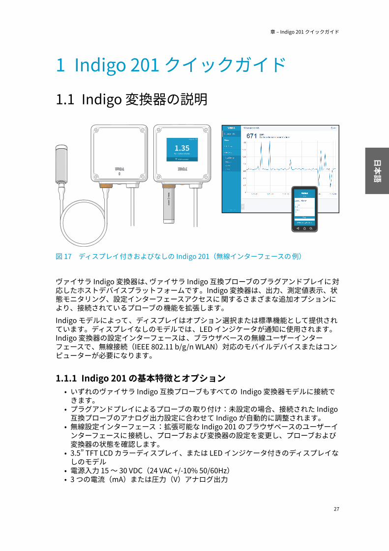
図 17 ディスプレイ付きおよびなしの Indigo 201(無線インターフェースの例)
ヴァイサラ Indigo 変換器は、ヴァイサラ Indigo 互換プローブのプラグアンドプレイに対応したホストデバイスプラットフォームです。Indigo 変換器は、出力、測定値表示、状態モニタリング、設定インターフェースアクセスに 関するさまざまな追加オプションにより、接続されているプローブの機能を拡張します。Indigo モデルによって、ディスプレイはオプション選択または標準機能として提供されています。ディスプレイなしのモデルでは、LED インジケータが通知に使用されます。Indigo 変換器の設定インターフェースは、ブラウザベースの無線ユーザーインターフェースで、無線接続(IEEE 802.11 b/g/n WLAN)対応のモバイルデバイスまたはコンピューターが必要になります。
1.1.1 Indigo 201 の基本特徴とオプション• いずれのヴァイサラ Indigo 互換プローブもすべての Indigo 変換器モデルに接続で
きます。• プラグアンドプレイによるプローブの 取り付け:未設定の場合、接続された Indigo
互換プローブのアナログ出力設定に合わせて Indigo が自動的に調整されます。• 無線設定インターフェース:拡張可能な Indigo 201 のブラウザベースのユーザーイ
ンターフェースに接続し、プローブおよび変換器の設定を変更し、プローブおよび変換器の状態を確認します。
• 3.5” TFT LCD カラーディスプレイ、または LED インジケータ付きのディスプレイなしのモデル
• 電源入力 15 ~ 30 VDC(24 VAC +/-10% 50/60Hz)• 3 つの電流(mA)または圧力(V)アナログ出力
章 – Indigo 201 クイックガイド
27
日本語

• 2 つの設定可能なリレー
1.2 入力および出力仕様表 3 入力と出力
特性 仕様アナログ出力 3 つの圧力(V)または電流(mA)出力:
• 0 ~ 10 V/0 ~ 5 V/0 ~ 1 V/1 ~ 5 V(最小負荷 1kΩ)
• 0 ~ 20 mA/4 ~ 20 mA(最大負荷 500 Ω)20 °C でのアナログ出力の精度 フルスケールの ± 0.1 %リレー 2 つの設定可能なリレー(VAC/VDC)
デバイス最大仕様(抵抗負荷):• 最大スイッチング電力 30 W/37.5 VA
UL 定格最大仕様(抵抗負荷):• AC:最大 28 V/0.5 A• DC:最大 40 V/0.24 A• 最大 30 VDC:
• 最大スイッチング電流 1 A• 最大スイッチング電力 30 W
電源入力 1) 15 ...30 VDC(24 VAC +/-10% 50/60Hz)最大電流 変換器と接続されているプローブで最大 1 A消費電力 変換器だけで最大 3 W(+ 接続されているプローブの
消費電力。プローブタイプにより異なります。)プローブコネクタ プローブ用 M12/5 コネクタまたはプローブケーブ
ルによる接続(ヴァイサラ Indigo 互換プローブ)ケーブル挿入口 2 つのオプション:変換器の底部にあるゴム製の導
入口および変換器の背面にあるシール付きの開口部ネジ端子の配線サイズ 0.2 ...1.5 mm2
1) 電気を安全に使用するために、過負荷保護機能付きの電源を使用することをお勧めします。
ユニットを改変したり、本書に記載されていない方法で使用したりしないでください。不適切な改変は、安全上の問題や機器の損傷に加えて、仕様に準じた動作が行われなくなったり、機器の寿命が短くなったりする原因となる場合があります。注意
M211876EN-F
28

1.3 Indigo 変換器の部品
2
3
4
5
7
6
1
図 18 Indigo 変換器の部品1 ディスプレイ(オプション)2 LED インジケーター(ディスプレイなしのモデル)3 プローブとプローブケーブルコネクタ 、固定用ホイール4 無線(WLAN)設定インターフェースの起動ボタン5 入力/出力ケーブル用の負荷を緩和できるゴム製の導入口6 変換器のトップカバー:LED/ディスプレイ、回路基板およびコネクタピン7 変換器基盤:入力および出力配線(ネジ端子)、取り付け基盤
本変換器には、ヴァイサラ Indigo 互換プローブのみを使用してください。互換性のないプローブまたはプローブケーブルを 接続しようとすると、機器が損傷することがあります。注意
章 – Indigo 201 クイックガイド
29
日本語

1.4 カバーの取り外しおよび設置
変換器のコネクタピンを損傷しないように、変換器カバーをまっすぐ引っ張って基盤から取り外します。捻ったり曲げたりしないでください。注意
1. 変換器カバーの 4 本のネジを緩めます。2. カバーを基盤から引っ張って外しやすくするために、変換器カバーを両側から途中
まで慎重に外します。3. 変換器カバーをまっすぐ引っ張って基盤から取り外します。捻ったり曲げたりしな
いでください。4. 変換器基盤を取り付け面に配置し、3 本のネジで基盤を設置します。図 19 (ペー
ジ 31) に示されたネジの位置を参照してください。
5. 入力/出力ケーブルを変換器内に配線します(「配線オプション (ページ 32)」を参照)。変換器の底部にある導入口にケーブルを通す場合は、ケーブルへの負荷が緩和されているかテストしてください。
6. 入力/出力ケーブルをネジ端子に接続し(「Indigo 変換器基盤 (ページ 31)」を参照)、完了したらカバーを再度取り付けます。
M211876EN-F
30

1.5 Indigo 変換器基盤
1 2 4
5
6
3
INDIGO 201 ANALOG
OUTPUT TRANSMITTER
Serial No. SX12345678
図 19 Indigo 201 変換器基盤の主要部品とネジの位置1 固定用ホイール内のプローブとプローブケーブルコネクタ2 無線(WLAN)設定インターフェースの起動ボタン3 背面から配線:シールを切って開きます4 負荷を緩和できるゴム製のケーブル導入口5 アナログ出力 1 ~ 3 とリレー A および B 用のネジ端子6 24 V 電源入力用のネジ端子
配線を接続する前に通電させないでください。注意
章 – Indigo 201 クイックガイド
31
日本語

1.6 配線オプション変換器の背面にある開口部または変換器の底部にあるゴム製の導入口から入力/出力ケーブルを配線できます。
1
2
Ø 7 ... 8 mm
図 20 Indigo 配線オプション1 背面から配線:シールを切って開きます2 変換器の底部にあるゴム製の導入口から配線
1. 入力/出力ケーブルを変換器の背面から配線するには、以下の手順に従います。a. ケーブルがちょうど通るように、必要な分だけシールを切り落とします。b. 開口部にケーブルを通して、必要に応じて負荷を緩和するケーブルグランドを取
り付けます。c. 背面からのみ配線する場合は、底部にある導入口に栓をするか密封します。
2. 入力/出力ケーブルを底部にあるゴム製の導入口から配線するには、以下の手順に従います。a. 入力/出力ケーブルを導入口から押し込みます。b. 導入口には負荷を緩和し、ケーブルを所定の位置に保持する機能があります。締
め付ける必要はありません。
ゴム製の導入口から配線する場合の推奨ケーブル直径は 7 ~ 8 mm です。異なるケーブルサイズを使用する場合は、想定どおりケーブルへの負荷が緩和されているかテストしてください。
M211876EN-F
32

1.7 プローブとケーブルの 取り付け
1
2
3
図 21 プローブとケーブルの Indigo への取り付け1 向きを示すマークと合うようにプローブをプローブコネクタに 挿入します。2 プローブは、固定用ホイールで所定の位置に固定します。決してプローブ本体をつか
んで回さないでください。3 プローブと同様にプローブケーブルを 接続します。ケーブルをコネクタに挿入し、固
定用ホイールを回しながら所定の位置に保持します。プローブによっては 、ケーブルでしか接続できない場合があります。接続手順については、プローブの取扱説明書を参照してください。
1. プローブ本体の向きを示すマークと合うようにプローブをプローブコネクタに 挿入します。
2. プローブをプローブコネクタに 保持し、固定用ホイールを反時計回りに回して所定の位置に固定します。取り付ける際は、プローブ本体をつかんで回さないでください。固定用ホイールのみを回してください。
章 – Indigo 201 クイックガイド
33
日本語

3. 以前の設定が存在しない場合(手動で設定を行っておらず、プローブを Indigo に初めて接続する場合)、Indigo は接続されたヴァイサラ Indigo 互換プローブのアナログ出力設定を自動的に採用します。
変換器の設定が、取り付けたプローブの設定と異なる場合は、新しいプローブを手動で設定してアナログ出力を有効にする必要があります。
1.8 無線設定インターフェースへの接続
Select WLAN to connect to:
1. WLAN XYZ
3. WLAN ABC
2. Indigo_ID[xx]
1 3
500ppm
WLAN on
Indigo 200
2
Carbon dioxide concentration
図 22 Indigo の無線設定インターフェースの有効化とアクセス1 無線接続起動ボタン2 Indigo ディスプレイ上の無線接続インジケータ(WLAN 記号)3 接続できる無線機器リストから Indigo(Indigo_ID[xx])を選択
無線設定インターフェースに接続するには、以下の手順に従います。1. 変換器の底部にある無線接続起動ボタンを押します。2. 無線設定インターフェースが利用可能になると、Indigo ディスプレイには接続通知
が表示されます。LED インジケータ付きの Indigo モデルでは、接続がアクティブになると LED が緑色に点滅します。
3. モバイルデバイスやコンピューターで無線接続メニューを開き、利用可能な接続のリストから Indigo_ID[xx] を選択します。
4. デバイスによっては 、Indigo に接続した後で無線接続インターフェースがブラウザで自動的に起動します。そうでない場合は、ブラウザアプリケーションを手動で起動する必要があります。
5. ブラウザで Indigo インターフェースを開くと、ログインするよう求められます。
無線設定インターフェースに接続できる機器は一度に 1 つだけです。
M211876EN-F
34

Indigo 201 無線設定インターフェースにアクセスする 手順の詳細またはトラブルシューティング手順については、『Indigo 201 User Guide』を参照してください。
1.9 無線設定インターフェースへのログインブラウザで Indigo の無線設定インターフェースを開くと、ログインするよう求められます。利用可能なユーザーレベルは、次の 2 つです。
• User:すべてのユーザーが 利用可能な表示専用アクセス。パスワードは不要です。• Admin:パスワードで保護されたアクセス。設定を変更するには、管理者としてログ
インする必要があります。
図 23 Indigo ログイン画面
ログインするには、以下の手順に従います。1. ユーザー名とパスワードを入力します。
a. ユーザーとしてログイン(表示専用アクセス、設定権限なし)するには、[User name] ドロップダウンから [User] を選択します。[Password] フィールドは空のままにします。
b. 管理者としてログイン(設定する場合は必要)するには、[User name] ドロップダウンから [Admin] を選択し、管理者パスワード(初期設定:12345)を[Password] フィールドに入力します。
章 – Indigo 201 クイックガイド
35
日本語
2. ログイン資格情報を入力したら、[Log in] を選択します。無線設定インターフェースが [Measurements] 画面で開きます。
ユーザーレベル(User または Admin)は、すべてのメニュー画面の右上角に表示されます。ユーザーレベルを変更するには、右上隅にあるユーザーアイコンまたは管理者アイコンを選択します。
1.10 無線インターフェースメニューIndigo 変換器は、ブラウザベースの無線設定インターフェースを使用して設定します
(IEEE 802.11 b/g/n WLAN 無線接続対応のモバイルデバイスまたはコンピューターが必要です)。無線インターフェースを使用すると、プローブと変換器の設定と校正に加えて、測定データと状態情報を表示できます。
M211876EN-F
36

1
2
3
4
5
図 24 無線設定インターフェース、デスクトップブラウザ画面1 Measurements:接続されているプローブの測定データが表示されます。2 Status:Indigo および接続されているプローブの状態(通知やアラームなど)に関す
る情報が含まれます。3 Calibration:基準を使用してプローブを校正および調整します。利用可能なオプ
ション(調整点など)は、プローブモデルによって 異なります。4 Settings:接続および表示設定、出力、リレー、プローブ固有の設定、機器の一般環
境設定を行うためのオプションが含まれます。• [General] サブメニュー:機器情報および一般設定、無線接続および表示設
定• [Outputs] サブメニュー:アナログ出力 1 ~ 3 の設定オプション• [Relays] サブメニュー:リレー A および B を制御するための設定• [Probe] サブメニュー:環境補正やフィルタリング係数などのプローブ固有
の設定5 メニューおよび測定情報のメイン表示領域(デスクトップブラウザの例)
章 – Indigo 201 クイックガイド
37
日本語

M211876EN-F
38

1 Indigo 201 快速指南1.1 Indigo 变送器简介
1.35% | Carbon dioxide
WLAN is activated
Indigo 201
图 25 带和不带显示屏的 Indigo 201、无线界面示例
Vaisala Indigo 变送器是用于 Vaisala Indigo 兼容探头的即插即用的主机设备平台。Indigo 变送器通过用于输出、测量值查看、状态监控和配置界面访问的多种附加选项,扩展了连接的探头的功能。根据不同的 Indigo 型号,显示屏可作为选件提供,也可作为标准功能提供。在无显示屏型号中,使用 LED 指示灯来进行通知。Indigo 变送器的配置界面是基于浏览器的无线用户界面,它要求支持无线连接 (IEEE 802.11 b/g/n WLAN) 的移动设备或计算机。
1.1.1 Indigo 201 基本功能和选件• 与 Vaisala Indigo 兼容的所有探头可以连接到所有 Indigo 变送器型号• 即插即用的探头安装:未配置时,Indigo 自动采用已连接的 Indigo 兼容探头的模拟
输出配置• 无线配置界面:连接到可扩展的基于浏览器的 Indigo 201 用户界面来更改探头和变送
器设置、查看测量值、查看探头和变送器的状态• 3.5 英寸 TFT LCD 彩色显示屏或带 LED 指示灯、无显示屏的型号• 电源输入 15 ...30 VDC (24 VAC +/-10% 50/60Hz)• 3 个电流 (mA) 或电压 (V) 模拟输出• 2 个可配置的继电器
章节 – Indigo 201 快速指南
39
中文

1.2 输入和输出规格表 4 输入和输出
参数 规格模拟输出 3 个电压 (V) 或电流 (mA) 输出:
• 0 … 10 V / 0 … 5 V / 0 … 1 V / 1 … 5 V(最小负载1kΩ)
• 0 … 20 mA / 4 … 20 mA(最大负载 500 Ω)20 °C 时模拟输出的精确度 满标的 ± 0.1%继电器 2 个可配置的继电器 (VAC/VDC)
设备最高规格(电阻负载):• 最大切换功率 30 W / 37.5 VAUL 认定的最高规格(电阻负载):
• 交流:最大 28 V / 0.5 A• 直流:最大 40 V / 0.24 A• 最大 30 VDC:
• 最大切换电流 1 A• 最大切换功率 30 W
电源输入 1) 15 ...30 VDC (24 VAC +/-10% 50/60Hz)最大电流 变送器和连接的探头最大电流为 1 A功耗 变送器最大功耗为 3 W(外加连接的探头,功耗随探
头型号而异)探头接头 采用 M12/5 接头来连接探头或探头电缆(Vaisala
Indigo 兼容探头)电缆馈通 2 个选件:变送器底部的橡胶导通,变送器背部的开
口密封螺钉端子线尺寸 0.2 ...1.5 mm2
1) 推荐使用有过载保护的电源,以确保用电安全。
不要改动设备或者在使用设备时采用未在文档中描述的方式。不正确的改动可能导致安全危险、设备损坏、未能按照规范执行或者缩短设备使用寿命。警告
M211876EN-F
40

1.3 Indigo 变送器部件
2
3
4
5
7
6
1
图 26 Indigo 变送器部件1 显示屏(可选)2 LED 指示灯(在无显示屏型号中)3 探头和探头电缆接头,锁轮4 无线 (WLAN) 配置界面激活按钮5 输入/输出电缆的橡胶导通(带张力消除器)6 变送器的顶盖:LED/显示屏、电路板和接头针脚7 变送器基座:输入和输出接线(螺钉端子)、安装基座
请只将与 Vaisala Indigo 兼容的探头用于变送器。尝试连接不兼容的探头或探头电缆可能损坏设备。警告
章节 – Indigo 201 快速指南
41
中文

1.4 打开和安装
为避免损坏变送器的接头针,请将变送器顶盖呈直角从基座上拉下。不要扭绞或弯曲。警告
1. 松开变送器顶盖上的 4 颗螺钉。2. 慎重地从两边将变送器顶盖打开一部分,以便将顶盖从基座上拉下。3. 以直角方向将变送器顶盖从基座上拉下。不要扭绞或弯曲。4. 将变送器基座放置于安装面上并且用 3 颗螺钉安装它。请参见图 27 (页 43)中的螺
钉位置。
5. 将输入/输出电缆引导到变送器内(参见配线选项 (页 44))。如果您正在通过变送器底部的导通进行配线,请测试张力消除器适用于您的电缆。
6. 将输入/输出电缆的配线连接到螺钉端子(参见 Indigo 变送器基座 (页 43))并且在完成后重新连接顶盖。
M211876EN-F
42

1.5 Indigo 变送器基座
1 2 4
5
6
3
INDIGO 201 ANALOG
OUTPUT TRANSMITTER
Serial No. SX12345678
图 27 Indigo 201 变送器基座主部件和螺钉位置1 锁轮里的探头和探头电缆接头2 无线 (WLAN) 配置界面激活按钮3 从背面接线:切开密封件4 橡胶电缆导通(带张力消除器)5 模拟输出 1-3 和继电器 A 和 B 的螺钉端子6 24 V 电源输入的螺钉端子
在连接好电线前请不要接通电源。警告
章节 – Indigo 201 快速指南
43
中文

1.6 配线选项您可以引导输入/输出电缆穿过变送器背部的开口,或者穿过变送器底部的橡胶导通。
1
2
Ø 7 ... 8 mm
图 28 Indigo 配线选项1 从背面接线:切开密封件2 配线穿过变送器底部的橡胶导通
1. 要引导输入/输出电缆穿过变送器背部:a. 根据需要切去尽可能多的密封件,以便适合您的电缆穿过开口。b. 引导电缆穿过开口并且根据需要连接张力消除器。c. 如果您仅是穿过背部,则堵上或密封底部的导通。
2. 要引导输入/输出电缆穿过底部的橡胶导通:a. 将输入/输出电缆引推过导通。b. 该导通提供张力消除器并且将电缆固定到位。不需要拧紧。
用于引导电缆穿过橡胶导通的建议电缆直径为 7 ... 8 毫米。如果您使用不同的电缆尺寸,则测试张力消除器是否按预期工作。
M211876EN-F
44

1.7 连接探头和电缆
1
2
3
图 29 将探头和电缆连接到 Indigo1 将探头插入探头接头并使标记朝外。2 使用锁轮将探头锁定到位。请勿转动探头主体。3 按与探头相同的方式连接探头电缆:将电缆插入接头并转动锁轮将其固定到位。请注
意,某些探头只能使用一根电缆连接:有关连接说明,请参见相关探头的文档。
1. 将探头插入探头接头并使探头主体上的标记朝外。2. 在探头接头中固定探头并逆时针转动锁轮使其锁定到位。连接时请勿转动探头主体,
而是使用锁轮进行操作。3. 如果没有以前的配置(即首次将探头连接到 Indigo,未手动设置过配置),Indigo 自
动采用连接的 Vaisala Indigo 兼容探头的模拟输出设置。
如果变送器的配置不同于连接的探头的配置,您必须手动配置新探头以启用模拟输出。
章节 – Indigo 201 快速指南
45
中文
1.8 连接到无线配置界面
Select WLAN to connect to:
1. WLAN XYZ
3. WLAN ABC
2. Indigo_ID[xx]
1 3
500ppm
WLAN on
Indigo 200
2
Carbon dioxide concentration
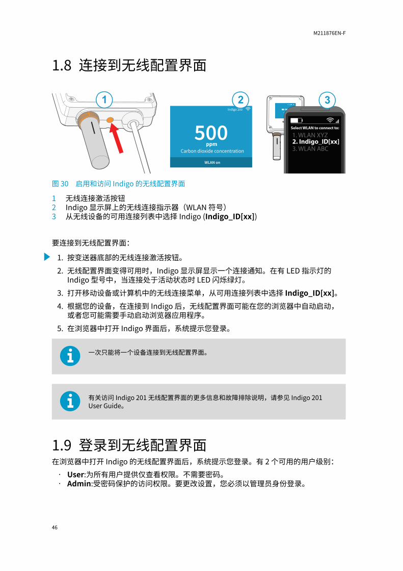
图 30 启用和访问 Indigo 的无线配置界面1 无线连接激活按钮2 Indigo 显示屏上的无线连接指示器(WLAN 符号)3 从无线设备的可用连接列表中选择 Indigo (Indigo_ID[xx])
要连接到无线配置界面:1. 按变送器底部的无线连接激活按钮。2. 无线配置界面变得可用时,Indigo 显示屏显示一个连接通知。在有 LED 指示灯的
Indigo 型号中,当连接处于活动状态时 LED 闪烁绿灯。3. 打开移动设备或计算机中的无线连接菜单,从可用连接列表中选择 Indigo_ID[xx]。4. 根据您的设备,在连接到 Indigo 后,无线配置界面可能在您的浏览器中自动启动,
或者您可能需要手动启动浏览器应用程序。5. 在浏览器中打开 Indigo 界面后,系统提示您登录。
一次只能将一个设备连接到无线配置界面。
有关访问 Indigo 201 无线配置界面的更多信息和故障排除说明,请参见 Indigo 201User Guide。
1.9 登录到无线配置界面在浏览器中打开 Indigo 的无线配置界面后,系统提示您登录。有 2 个可用的用户级别:
• User:为所有用户提供仅查看权限。不需要密码。• Admin:受密码保护的访问权限。要更改设置,您必须以管理员身份登录。
M211876EN-F
46

图 31 Indigo 登录视图
要登录:1. 输入用户名和密码:
a. 要以用户(仅查看权限,无配置权)身份登录,请从 User name(用户名)下拉列表中选择 User(用户)。使 Password(密码)字段留空。
b. 要以管理员(配置时需要)身份登录,请在 User name(用户名)下拉列表中选择 Admin(管理员)并在 Password(密码)字段中键入管理员密码(默认值:12345)。
2. 在输入登录凭据后选择 Log in(登录)。无线配置界面将在 Measurements(测量值)视图中打开。
用户级别(User 或 Admin)显示在所有菜单视图的右上角。选择右上角的 user/admin 图标来更改用户级别。
1.10 无线界面菜单使用基于无线浏览器的配置界面配置 Indigo 变送器(需要支持 IEEE 802.11 b/g/n WLAN无线连接的移动设备或计算机)。除了进行探头和变送器配置和校准外,您还可以使用无线界面查看测量数据和状态信息。
章节 – Indigo 201 快速指南
47
中文

1
2
3
4
5
图 32 无线配置界面,桌面浏览器视图1 Measurements:显示连接的探头的测量数据2 Status:包含有关 Indigo 和连接的探头的状态信息(例如通知和警报)3 Calibration:使用基准值校准和调校探头。可用选项(例如调校点)随探头型号而
异。4 Settings:包含一些选项用于配置连接和显示设置、输出、继电器、探头特定设置和一
般设备首选项• General(常规)子菜单:包含设备信息和常规设置、无线连接和显示设置• Outputs(输出)子菜单:包含模拟输出 1-3 的配置选项• Relays(继电器)子菜单:包含用于控制继电器 A 和 B 的设置• Probe(探头)子菜单:包含探头特定设置,如环境补偿和滤波因子
5 菜单和测量信息的主显示区域(桌面浏览器显示示例)
M211876EN-F
48

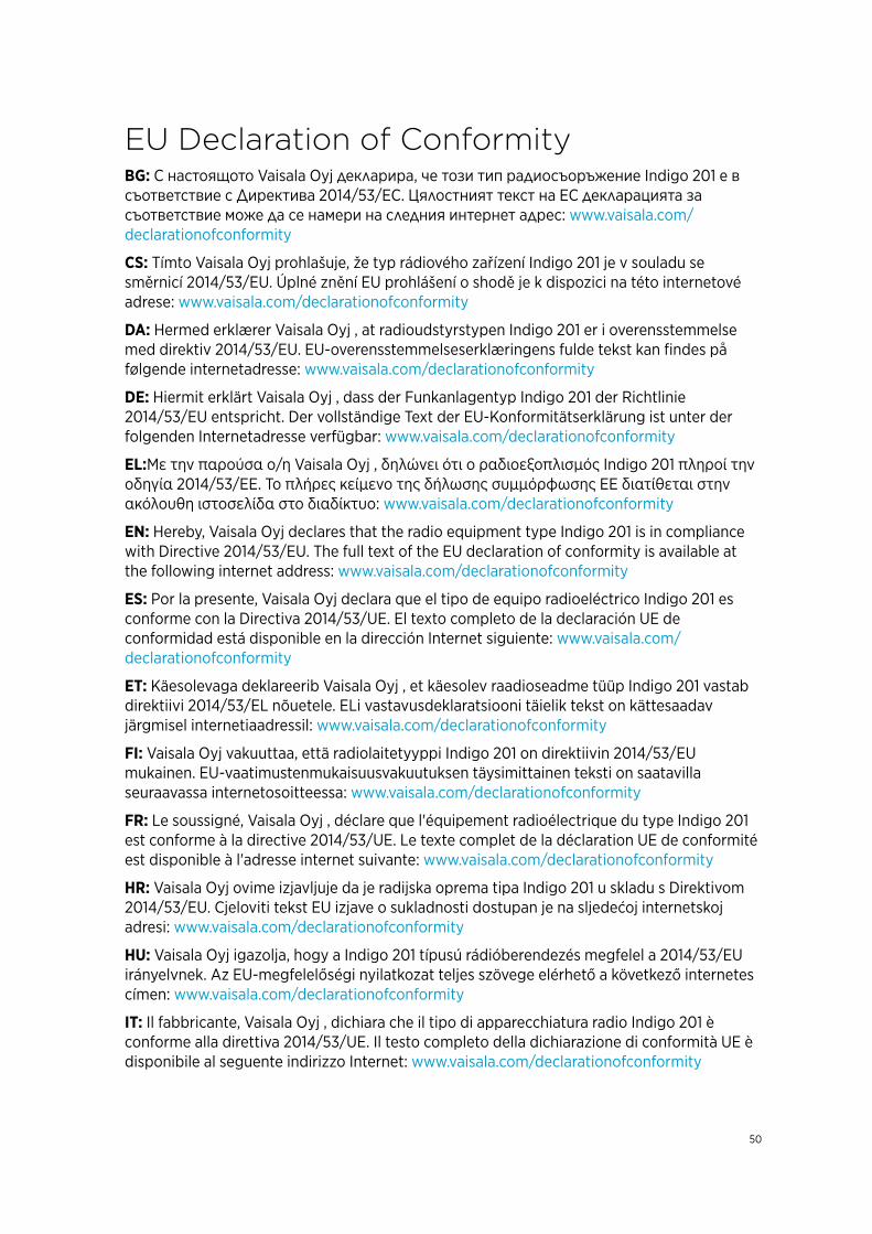
EU Declaration of ConformityBG: С настоящото Vaisala Oyj декларира, че този тип радиосъоръжение Indigo 201 е всъответствие с Директива 2014/53/ЕС. Цялостният текст на ЕС декларацията засъответствие може да се намери на следния интернет адрес: www.vaisala.com/declarationofconformity
CS: Tímto Vaisala Oyj prohlašuje, že typ rádiového zařízení Indigo 201 je v souladu sesměrnicí 2014/53/EU. Úplné znění EU prohlášení o shodě je k dispozici na této internetovéadrese: www.vaisala.com/declarationofconformity
DA: Hermed erklærer Vaisala Oyj , at radioudstyrstypen Indigo 201 er i overensstemmelsemed direktiv 2014/53/EU. EU-overensstemmelseserklæringens fulde tekst kan findes påfølgende internetadresse: www.vaisala.com/declarationofconformity
DE: Hiermit erklärt Vaisala Oyj , dass der Funkanlagentyp Indigo 201 der Richtlinie2014/53/EU entspricht. Der vollständige Text der EU-Konformitätserklärung ist unter derfolgenden Internetadresse verfügbar: www.vaisala.com/declarationofconformity
EL:Με την παρούσα ο/η Vaisala Oyj , δηλώνει ότι ο ραδιοεξοπλισμός Indigo 201 πληροί τηνοδηγία 2014/53/ΕΕ. Το πλήρες κείμενο της δήλωσης συμμόρφωσης ΕΕ διατίθεται στηνακόλουθη ιστοσελίδα στο διαδίκτυο: www.vaisala.com/declarationofconformity
EN: Hereby, Vaisala Oyj declares that the radio equipment type Indigo 201 is in compliancewith Directive 2014/53/EU. The full text of the EU declaration of conformity is available atthe following internet address: www.vaisala.com/declarationofconformity
ES: Por la presente, Vaisala Oyj declara que el tipo de equipo radioeléctrico Indigo 201 esconforme con la Directiva 2014/53/UE. El texto completo de la declaración UE deconformidad está disponible en la dirección Internet siguiente: www.vaisala.com/declarationofconformity
ET: Käesolevaga deklareerib Vaisala Oyj , et käesolev raadioseadme tüüp Indigo 201 vastabdirektiivi 2014/53/EL nõuetele. ELi vastavusdeklaratsiooni täielik tekst on kättesaadavjärgmisel internetiaadressil: www.vaisala.com/declarationofconformity
FI: Vaisala Oyj vakuuttaa, että radiolaitetyyppi Indigo 201 on direktiivin 2014/53/EUmukainen. EU-vaatimustenmukaisuusvakuutuksen täysimittainen teksti on saatavillaseuraavassa internetosoitteessa: www.vaisala.com/declarationofconformity
FR: Le soussigné, Vaisala Oyj , déclare que l'équipement radioélectrique du type Indigo 201est conforme à la directive 2014/53/UE. Le texte complet de la déclaration UE de conformitéest disponible à l'adresse internet suivante: www.vaisala.com/declarationofconformity
HR: Vaisala Oyj ovime izjavljuje da je radijska oprema tipa Indigo 201 u skladu s Direktivom2014/53/EU. Cjeloviti tekst EU izjave o sukladnosti dostupan je na sljedećoj internetskojadresi: www.vaisala.com/declarationofconformity
HU: Vaisala Oyj igazolja, hogy a Indigo 201 típusú rádióberendezés megfelel a 2014/53/EUirányelvnek. Az EU-megfelelőségi nyilatkozat teljes szövege elérhető a következő internetescímen: www.vaisala.com/declarationofconformity
IT: Il fabbricante, Vaisala Oyj , dichiara che il tipo di apparecchiatura radio Indigo 201 èconforme alla direttiva 2014/53/UE. Il testo completo della dichiarazione di conformità UE èdisponibile al seguente indirizzo Internet: www.vaisala.com/declarationofconformity
50

LT: Aš, Vaisala Oyj , patvirtinu, kad radijo įrenginių tipas Indigo 201 atitinka Direktyvą 2014/53/ES. Visas ES atitikties deklaracijos tekstas prieinamas šiuo interneto adresu:www.vaisala.com/declarationofconformity
LV: Ar šo Vaisala Oyj deklarē, ka radioiekārta Indigo 201 atbilst Direktīvai 2014/53/ES. Pilns ES atbilstības deklarācijas teksts ir pieejams šādā interneta vietnē: www.vaisala.com/declarationofconformity
MT: B'dan, Vaisala Oyj , niddikjara li dan it-tip ta' tagħmir tar-radju Indigo 201 huwa konformi mad-Direttiva 2014/53/UE. It-test kollu tad-dikjarazzjoni ta' konformità tal-UE huwa disponibbli f'dan l-indirizz tal-Internet li ġej: www.vaisala.com/declarationofconformity
NL: Hierbij verklaar ik, Vaisala Oyj , dat het type radioapparatuur Indigo 201 conform is met Richtlijn 2014/53/EU. De volledige tekst van de EU-conformiteitsverklaring kan worden geraadpleegd op het volgende internetadres: www.vaisala.com/declarationofconformity
PL: Vaisala Oyj niniejszym oświadcza, że typ urządzenia radiowego Indigo 201 jest zgodny z dyrektywą 2014/53/UE. Pełny tekst deklaracji zgodności UE jest dostępny pod następującym adresem internetowym: www.vaisala.com/declarationofconformity
PT: O(a) abaixo assinado(a) Vaisala Oyj declara que o presente tipo de equipamento de rádio Indigo 201 está em conformidade com a Diretiva 2014/53/UE. O texto integral da declaração de conformidade está disponível no seguinte endereço de Internet:www.vaisala.com/declarationofconformity
RO: Prin prezenta, Vaisala Oyj declară că tipul de echipamente radio Indigo 201 este în conformitate cu Directiva 2014/53/UE. Textul integral al declarației UE de conformitate este disponibil la următoarea adresă internet: www.vaisala.com/declarationofconformity
SK: Vaisala Oyj týmto vyhlasuje, že rádiové zariadenie typu Indigo 201 je v súlade so smernicou 2014/53/EÚ. Úplné EÚ vyhlásenie o zhode je k dispozícii na tejto internetovej adrese: www.vaisala.com/declarationofconformity
SL: Vaisala Oyj potrjuje, da je tip radijske opreme Indigo 201 skladen z Direktivo 2014/53/EU. Celotno besedilo izjave EU o skladnosti je na voljo na naslednjem spletnem naslovu:www.vaisala.com/declarationofconformity
SV: Härmed försäkrar Vaisala Oyj att denna typ av radioutrustning Indigo 201 överensstämmer med direktiv 2014/53/EU. Den fullständiga texten till EU-försäkran om överensstämmelse finns på följande webbadress: www.vaisala.com/declarationofconformity
51