Vacuum Solutions Application Support Service LEYBOLD VACUUM
30
DIVAC 0.6 L; 1.2 L; 2.2 L Laboratory Pump with Modular Accessories Cat. Nos.: 135 00 135 61 135 01 135 62 135 02 135 63 135 03 135 70 135 04 135 71 135 06 135 72 135 07 135 73 135 08 135 80 135 09 135 81 135 10 135 82 135 12 135 83 135 13 135 85 134 14 135 87 135 15 135 90 135 16 135 91 135 40 135 92 135 50 135 93 135 60 Operating Instructions GA 01.417/3.02 These Operating Instructions apply to all models of the DIVAC pump series and to all DIVAC pump systems SR..., SH..., SC... and SCC... as well as upgrade modules DIVATRONIC DT 1 and following. DIVAC Vacuum Solutions Application Support Service LEYBOLD VACUUM
Transcript of Vacuum Solutions Application Support Service LEYBOLD VACUUM

DIVAC0.6 L; 1.2 L; 2.2 L
Laboratory Pump withModular Accessories
Cat. Nos.:135 00 135 61135 01 135 62135 02 135 63135 03 135 70135 04 135 71135 06 135 72135 07 135 73135 08 135 80135 09 135 81135 10 135 82135 12 135 83135 13 135 85134 14 135 87135 15 135 90135 16 135 91135 40 135 92135 50 135 93135 60
Operating Instructions
GA 01.417/3.02
These Operating Instructions apply to allmodels of the DIVAC pump series and to allDIVAC pump systems SR..., SH..., SC...and SCC... as well as upgrade modulesDIVATRONIC DT 1 and following.
DIVAC
Vacuum Solutions Application Support Service LEYBOLD VACUUM

GA/ET 01.417/3.02 - 01/98
Contents
2
ContentsPage
1 Description . . . . . . . . . . . . . . . . . . . . . . . . . . 31.1 System versions . . . . . . . . . . . . . . . . . . . . . . . 51.1.1 Vacuum pump with two separators
(SR systems) . . . . . . . . . . . . . . . . . . . . . . . . . 51.1.2 Vacuum pump with separator and
high performance condenser (SH systems) . . 51.1.3 Vacuum pump with separator, high
performance condenser and a vacuum controller DIVATRONIC DT 1 (SC systems) . . 6
1.1.4 Vacuum pump with separator, highperformance condenser and two DIVATRONIC DT 1 controllers (SCC system) . 6
2 Safety information . . . . . . . . . . . . . . . . . . . . 7
3 Operation . . . . . . . . . . . . . . . . . . . . . . . . . . . 83.1 Operating conditions for the vacuum pumps
of the DIVAC system . . . . . . . . . . . . . . . . . . . 83.2 Operation of the pump system . . . . . . . . . . . . 83.2.1 Operation with baseplate and two separators . 83.2.2 Operation with baseplate, separator and
high performance condenser . . . . . . . . . . . . 103.2.3 Operation with baseplate, separator,
high performance condenser, control unitand one DIVATRONIC DT 1 controller . . . . . 11
3.3 Start up . . . . . . . . . . . . . . . . . . . . . . . . . . . . 143.3.1 Adjustment of the vacuum setpoint . . . . . . . . 143.3.2 Hysteresis adjustment . . . . . . . . . . . . . . . . . 143.3.3 Automatic setpoint correction . . . . . . . . . . . . 143.3.4 Starting the evacuation process . . . . . . . . . . 143.3.5 Stopping the evacuation process . . . . . . . . . 153.3.6 Restart after stopping a running
evacuation process . . . . . . . . . . . . . . . . . . . 153.3.7 Evacuation without control for maximum
vacuum (drying mode) . . . . . . . . . . . . . . . . . 153.3.8 Venting of the system . . . . . . . . . . . . . . . . . . 153.4 Operation with baseplate, separator,
high performance condenser, control unitand two DIVATRONIC DT 1 (SCC) . . . . . . . . 16
3.4.1 Upgrading of existing DIVAC systems (SH/SC to SC/SCC) with DIVATRONICmodules . . . . . . . . . . . . . . . . . . . . . . . . . . . . 17
3.4.1.1 System with already present baseplate, separator and condenser (SH system) . . . . . 17
3.4.1.2 System with already present baseplate,separator, condenser, control unit,support post and one DIVATRONIC DT 1 controller . . . . . . . . . . . . . . . . . . . . . . . . . . . 17
3.5 Gas ballast option . . . . . . . . . . . . . . . . . . . . 193.6 Shut down . . . . . . . . . . . . . . . . . . . . . . . . . . 203.7 Troubleshooting . . . . . . . . . . . . . . . . . . . . . . 203.7.1 System without DIVATRONIC DT 1 controller
(SH/SR systems) . . . . . . . . . . . . . . . . . . . . . 203.7.2 System with one DIVATRONIC DT 1
controller . . . . . . . . . . . . . . . . . . . . . . . . . . . 20
3.7.3 System with two DIVATRONIC DT 1 controllers (SCC systems) . . . . . . . . . . . . . . 21
3.8 Exchanging diaphragms and valves plates . . 21
4 Technical data . . . . . . . . . . . . . . . . . . . . . . 23
5 Ordering information . . . . . . . . . . . . . . . . . 235.1 DIVAC pump system . . . . . . . . . . . . . . . . . . 235.2 Accessories for the modular DIVAC system . 245.3 DIVATRONIC modules . . . . . . . . . . . . . . . . . 25
6 Spare parts . . . . . . . . . . . . . . . . . . . . . . . . . 26
EC Declaration of Conformity . . . . . . . . . . 29
Before putting the unit into operation youmust read these Operating Instructions first.Observe the Operating Instructions whileoperating the unit in the sense of avoidinghazards and damage.
Indicates procedures that must be strictlyobserved to prevent hazards to persons.
Indicates procedures that must strictly beobserved to prevent damage to, ordestruction of the equipment.
Leybold Service
If a pump is returned to Leybold, indicate whether thepump free of substances damaging to health or whetherit is contaminated.
If it is contaminated also indicate the nature of thehazard. Leybold must return any pumps without a“Declaration of Contamination” to the sender’s address.
Figures
The references to figures, e.g. (1/2) consist of the Fig.No. and the item No. in that order.
Warning
Caution

GA/ET 01.417/3.02 - 01/98
DIVAC
Description
3
1 DescriptionThis range of vacuum pumps has been specificallydeveloped for use in the laboratory. Laboratoryapplications are particularly demanding with regard toprecision, reliability and ease of operation.The DIVAC range of vacuum pumps has beendeveloped on the basis of the well proven technology ofdiaphragm pumps.
With three different pumping speeds and the sameattainable ultimate pressure for each of these vacuumpumps and the modular accessories, the DIVAC pumpsystem can be optimally adapted to meet individualrequirements.
Examples of applications:
• Vacuum filtration• Vacuum distillation• Vacuum drying• Vacuum impregnation• on rotary evaporators• for sucking and pumping of gases• drying of gels
Fig. 1 Modular, fully equipped DIVAC system SCC 0.6 L - 1.2 L - 2.2 L
Key to Fig. 11 Vacuum pump 11 High performance condenser2 Mains switch 12 Glass flask for condensate3 Control unit 13 Attachment clamp4 Baseplate 14 Angled hose nozzle for the cooling water connection5 Attachment rod for the pump 15 Vacuum valve6 Support post for the condenser 16 Pump relief valve7 Support post for the controller unit 17 Venting valve at the DIVATRONIC DT 1 controller8 Separator 18 Vacuum controller DIVATRONIC DT 1 9 Cup for the separator 19 Mains switch of the vacuum controller DIVATRONIC DT 1 10 Hose nozzle
3 2 1 8 10 9
4
5
6
12
13
14
11
10
17
18
18
19
7
16 15 15

GA/ET 01.417/3.02 - 01/98
Features of the DIVAC Vacuum Pumps and the DIVAC System
• All system components are combined in one singleassembly, which can easily be exchanged orupgraded up to the fully equipped SCC... version(with two DIVATRONIC DT 1 controllers).
• Simple to move to an other location, since the entireassembly is arranged on a rugged baseplate so thatit can be moved safely.
• Because connectors are used throughout, individualcomponents can be easily disassembled.
• Compact design – small footprint.
• Starting with version SC... with separator, highperformance condenser and DIVATRONIC DT 1controller, all electrical connections are combined viaconnectors at the control unit.
• The installation of further laboratory components inslots, on support posts and cross bars of theassembly is possible without problems.
• The diaphragms and valves on the vacuum pump canbe easily exchanged.
• All parts of the pump´s head which come into contactwith the gas are capable of resisting aggressivemedia (material: PTFE, FFKM and PVDF).
• The vacuum pumps operate in a gas-tight manner,100% free of oil, maintenance-free and silently.
• A new valve system provides a high level ofcompatibility with vapours and condensate.
• Low ultimate vacuum pressures are attained quickly.
• Illuminated mains switch on the pump.
• Overtemperature protection for the vacuum pumpthrough a thermal overload protector.
• Pump systems can be arranged conveniently fromDIVAC modules and DIVAC diaphragm pumps; fourmodules are available (see Section 5.2).
Description
4

GA/ET 01.417/3.02 - 01/98
Description
1.1 System VersionsEach of the three pump systems SR..., SH... and SC...which are supplied ready for operation can be upgradedin a modular way right up to the fully equipped SCC...system for two vacuum chambers. Also beginning withone pump you may upgrade to each of the systems. TheDIVAC modules or the DIVATRONIC upgrades detailedin Section 5.2 are used for this.
For this refer to Section 3.
Ordering information is provided in Section 5.
1.1.1 Vacuum Pump with two Separators(SR Systems)
SR 0.6 L (pumping speed 0.6 m3 · h-1 )
SR 1.2 L (pumping speed 1.2 m3 · h-1 )
SR 2.2 L (pumping speed 2.2 m3 · h-1 )consisting of DIVAC module SR and DIVACdiaphragm pump(s) (see Section 5.1 andsubsequent sections)
Any solvent residues are separated on the pressure sideso as to prevent them from entering into the ambient air.On the suction side, a separator collects any particlesand droplets which might be present in the system. Thisprevents the pump from being contaminated andensures peak pump performance.
The separating vessel is made of a special kind of glassand it is protected against implosion.
5
1.1.2 Vacuum Pump with Separator andHigh Performance Condenser(SH Systems)
SH 0.6 L (pumping speed 0.6 m3 · h-1 )
SH 1.2 L (pumping speed 1.2 m3 · h-1 )
SH 2.2 L (pumping speed 2.2 m3 · h-1 )consisting of DIVAC module SH and DIVACdiaphragm pump(s) (see Section 5.1 andsubsequent sections)
The high performance condenser is employed to recoversolvents from the pumped gas in order to conserveresources and to protect the environment.
The condensed solvents are collected in a glass flask.The flask itself is attached by means of a clamp to theflange of the condenser.
Through the use of a recirculation cooler the efficiency ofcondensation may be increased considerably.
Refrigerant temperatures of 5 °C are optimum forefficient condensation and the resulting reduction ofemissions.
Recirculation thermostats free of HCFCs are availablefrom us upon request.
DIVAC
DIVAC
Fig. 2 DIVAC system SR 0.6 L - 1.2 L - 2.2 L Fig. 3 DIVAC system SH 0.6 L - 1.2 L - 2.2 L
GA/ET 01.417/3.02 - 01/98
Description
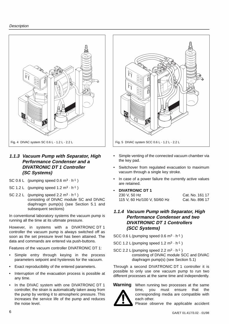
1.1.3 Vacuum Pump with Separator, HighPerformance Condenser and a DIVATRONIC DT 1 Controller(SC Systems)
SC 0.6 L (pumping speed 0.6 m3 · h-1 )
SC 1.2 L (pumping speed 1.2 m3 · h-1 )
SC 2.2 L (pumping speed 2.2 m3 · h-1 )consisting of DIVAC module SC and DIVACdiaphragm pump(s) (see Section 5.1 andsubsequent sections)
In conventional laboratory systems the vacuum pump isrunning all the time at its ultimate pressure.
However, in systems with a DIVATRONIC DT 1controller the vacuum pump is always switched off assoon as the set pressure level has been attained. Thedata and commands are entered via push-buttons.
Features of the vacuum controller DIVATRONIC DT 1:
• Simple entry through keying in the processparameters setpoint and hysteresis for the vacuum.
• Exact reproducibility of the entered parameters.
• Interruption of the evacuation process is possible atany time.
• In the DIVAC system with one DIVATRONIC DT 1controller, the strain is automatically taken away fromthe pump by venting it to atmospheric pressure. Thisincreases the service life of the pump and reducesthe noise level.
6
• Simple venting of the connected vacuum chamber viathe key pad.
• Switchover from regulated evacuation to maximumvacuum through a single key stroke.
• In case of a power failure the currently active valuesare retained.
• DIVATRONIC DT 1230 V, 50 Hz Cat. No. 161 17115 V, 60 Hz/100 V, 50/60 Hz Cat. No. 896 17
1.1.4 Vacuum Pump with Separator, HighPerformance Condenser and twoDIVATRONIC DT 1 Controllers (SCC Systems)
SCC 0.6 L (pumping speed 0.6 m3 · h-1 )
SCC 1.2 L (pumping speed 1.2 m3 · h-1 )
SCC 2.2 L (pumping speed 2.2 m3 · h-1 )consisting of DIVAC module SCC and DIVACdiaphragm pump(s) (see Section 5.1)
Through a second DIVATRONIC DT 1 controller it ispossible to only use one vacuum pump to run twodifferent processes at the same time and independently.
When running two processes at the sametime, you must ensure that thecorresponding media are compatible witheach other.Please observe the applicable accident
DIVACDIVAC
Warning
Fig. 4 DIVAC system SC 0.6 L - 1.2 L - 2.2 L Fig. 5 DIVAC system SCC 0.6 L - 1.2 L - 2.2 L

GA/ET 01.417/3.02 - 01/98
Safety Information
7
prevention regulations as well as all othergenerally accepted safety and healthprotection regulations.
Housing parts which are marked with thissymbol must only be opened after havingpulled the mains plug (interruption of theelectrical power supply connection).Housing parts which contain voltagecarrying components inside must only beopened by trained personnel.
• Always keep the Operating Instructions close at handnear to the unit.
• Note that the pump system and all system parts mustonly be used for the purpose they are intended for.
• Only connect the unit to properly installed mainsoutlets with a ground conductor.
• During all cleaning work make sure that no liquidsenter inside the housing.
• All three types of pump are protected againstoverheating by a thermal overload protector. If thisprotector has responded or if the power has failed,pull the mains plug so that the pump can not start upagain in an uncontrolled manner.
• Only use original spare parts from Leybold.
• Never expose any part of your body to the vacuum.
When installing the vacuum pump or the DIVACsystem, please observe the following:
• Select a secure place for the unit (flat surface).
• Make sure that the vacuum pump is securelyattached to the baseplate (for installation informationsee Section 3.2, Fig. 7 and subsequent figures). Thetwo ball pins (8/2) under the pump must be firmlyengaged.
• Laboratory devices or additional components whichare connected to a DIVAC pump or a DIVAC systemmust have the same pneumatic rating as the pumps.
• Operation of the high performance condenserrequires a cold water connection or a recirculatingcooler.
• The condenser must only be fitted at the dischargeside of the pump; if fitted on the intake side thereexists the risk of implosion.
• In case of simultaneous operation involving twodifferent gases, only such gases must be pumpedwhich can be mixed without danger.
• Do not operate the pump in explosion-hazardenvironments.
• Processes involving radioactive exposure should beavoided.
Before starting up
• Observe the safety regulations for the use of:
• acid,
• explosive,
• microbiological,
• radioactive,
• toxic media and other dangerous substances.
• Lead the external connection hoses on the suctionside to the vacuum chamber and on the pressure sideto the waste disposal unit or the discharge unit.
• Ensure that the upper gas discharge outlet on thecondenser is not blocked (danger of an overpressureas a result of a bent hose, for example).
• Make sure that the outlet of the pump is not sealed ornarrowed.
• Lay the connecting hoses for cooling the condenserbetween condenser and water supply and drain.
• Before switching on check the seating of all hoseconnections first.
• Compare the locally available mains voltage to thedata provided on the name plate.
• Never operate the pump with the sealing stopper (redplastic cap) in place at the pump´s outlet while theinlet is open at the same time.
• Already before commissioning the pump remove theplastic caps. Otherwise there exists the danger thatsomeone may be injured by caps ejected off from thepump.
Warning
2 Safety Information

GA/ET 01.417/3.02 - 01/98
Operation
8
3.1 Operating Conditions forthe Vacuum Pumps ofthe DIVAC System
• Permissible ambient temperatures: +5 °C to + 40 °C.
• Pumping of liquids is not permissible.
• Permissible temperatures for the gases which are to
be pumped: +5 °C to + 40 °C.
• The pump must never be started up against anoverpressure (on the pressure side).
• During standstill (power failure, for example) thepump must be pneumatically relieved. In the case ofpump systems (SC/SCC) with a DIVATRONIC DT 1controller, the pump is relieved automatically throughthe relief valve.
• Any throttling or control of quantity of the air or gasshould only be done in the line on the suction side. Ifthrottling or control is only possible on the pressureside, you must not exceed the max. overpressurespecification of the pump in each case.
• In order to ensure adequate cooling of the pump, theventilation slits on the vacuum pump must not beobstructed.
• The vacuum pumps may also be operatedcontinuously at their ultimate pressure.
3.2 Operation of the PumpSystem
• The pump is switched on or off through the mainsswitch (see Fig. 1, item 2).
• In case of operation with one or more DIVATRONICDT 1 controllers:
The DIVATRONIC DT 1 controller(s) is/are switchedon and off through the mains switch (1/19).
3.2.1 Operation with Baseplate and twoSeparators
Corresponds to the DIVAC system SR... (see Section 2).
The Baseplate
• The basis for the DIVAC assembly is a pump inconnection with a baseplate.
• The mounting system ensures that the individualpump models seated on the baseplate can beexchanged without problems (see Fig. 5).
• Fixing the pump to the baseplate:
Place the pump with its fixing components on thebaseplate and align the pump.
Insert the two fixing rods through the fixingcomponents of the pump and the baseplate.
Make sure that the ball pins (8/2) engage positively.
Before exchanging the pumps, the pumpwhich has been attached to the baseplatemust be disconnected from the mains bypulling the mains plug.
DIVAC
3 Operation
Warning
Fig. 6 DIVAC - Pump without accessories
Intake side
Pressure side

GA/ET 01.417/3.02 - 01/98
Operation
Installation / Upgrading
In order to be able to attach a pump on the baseplate, asystem mount must be attached to the pump first.
In the case of the DIVAC system modules(SR/SH/SC/SCC) this system mount has already beenattached in the factory. When ordering baseplatesseparately (see Section 5.3 – Accessories for themodular DIVAC system), the system mounts areincluded. They are installed according to Fig. 7.
• Unscrew the rubber feet under the pump by turningthese in the anti-clockwise direction.
• Attach the system mount to the pump according toFig. 7.
The Separator
• The cups for the separator vessels may be shifted asrequired after loosening the fixing screw.
Installation
• Insert the cups for the separator vessels into the slotpointing upwards on the baseplate.
• Affix the vessels by clamping:
Tighten the fixing screw in the bottom of the cup.
• Provide the hose connections according to Fig. 8 (forhose materials see Section 6 - Spare Parts).
Use only such a hose material which is ableto resist the kind of media used.
Emptying / Cleaning of the Separator
• Unscrew the two connection nozzles.
• Take the separator vessel out of its cup, properlydispose of the contents and rinse the vessel.
• Place the vessel back in its cup.
• Screw the connection nozzles back on.
The gas hoses connected to the connection nozzles onthe separator vessels may be interchanged.
9
DIVAC
DIVAC
Fig. 7 Installation of the fixing components for the DIVAC Fig. 8 Hose connections on the DIVAC system SR 0.6 L - 1.2 L - 2.2 L
Caution
from the vacuumchamber
to the wastedisposal unit
Hose length, approx. Inside diameter of the hose
150 mm each 10 mm
Key to Fig. 81 Separating vessel2 Ball pins
System mount

Operation
3.2.2 Operation with Baseplate, Separatorand High Performance Condenser
• Corresponds to DIVAC system SH... (see also Fig. 3),consisting of DIVAC module SH and DIVACdiaphragm pump(s), see Section 5.1 and subsequentsections.
The baseplate (see Section 3.2.1)
The separator (see Section 3.2.1).
The high performance condenser (see Section 3.2.2).
• In case of operation with the high performancecondenser, a cold water connection or a recirculatingcooler is required.
Installation of the condenser:
• Required tools:
1 hex. socket wrench 5 mm.
• The high performance condenser is suppliedattached to the support post.
• The support post (its fixing section) is pushed into aslot pointing up on the baseplate so that the screwsfor attaching the condenser point in the direction ofthe pump.
• Fix the support post to the baseplate (by tighteningthe hex. socket screw of the support post).
• Provide the hose connections as shown in Fig. 9 (forhose materials see Section 6 - Spare parts).
• For installing the DIVAC pump, see Section 3.2, Fig.7.
Use only such a hose material which is ableto resist the kind of media used.
• The angled hose nozzles for the cooling waterconnection have been designed to accept hoseshaving an inside diameter of 8 mm.
• In the case of the condenser you must make sure thatthe hose connections for gas and cooling water (Fig.9) are assigned correctly. The inlet and the outlet forthe (gas) connections must not be interchanged.
• When providing the hose connections, take care thatthe hose connection for the condensate inlet (gas) isplaced lower than that for the pump outlet. Thuspossibly produced condensate can not enter thepump head.
• The cooling water supply and discharge lines may beconnected as convenient to the two hose nozzles.
10 GA/ET 01.417/3.02 - 01/98
DIVAC
Ensure that the upper gas discharge of thecondenser is not blocked (danger of anoverpressure as a result of a bent hose, forexample).
Fig. 9 Hose connections on the DIVAC SH system
Caution
Hose No. Hose length, approx. Inside diameter of the hose
1 150 mm 10 mm
2 220 mm 10 mm
from the vacuumchamber
to the wastedisposal unit
Cooling water
1
2
CautionLay the hose so that it slopes down andaway, so that any produced condensate mayreliably flow into the receiver
Receiver

GA/ET 01.417/3.02 - 01/98 11
Operation
Emptying / cleaning the condenser
• Carefully pull off the coloured holding clip while at thesame time taking hold of the flask.
• Empty the glass flask and clean it. Observe theapplicable safety regulations.
• Fit the glass flask back in place and push thecoloured clip back on.
Height adjustment of the condenser
• Loosen the two hex. socket screws on the supportpost for the condenser.
• Move the condenser mount along the slot in thesupport post to the desired position.
• Tighten the hex. socket screws.
3.2.3 Operation with Baseplate, Separator,High Performance Condenser,Control Unit and one DIVATRONICDT 1 Controller
• Corresponds to DIVAC system SC... (see Fig. 4).
The baseplate (see Section 3.2.1)
The separator (see Section 3.2.1).
The high performance condenser (see Section 3.2.2).
The vacuum controller DIVATRONIC DT 1
Through the DIVATRONIC DT 1 vacuum controller it ispossible to control vacuum processes which require awell defined vacuum. Data and commands which areentered via the key pad precisely control the vacuum ina reproducible manner and in such a way that thevacuum can be influenced at any time.
The following can be entered and constantly controlled:
• Setpoint vacuum pressure.
• Setpoint hysteresis in “mbar” or “%”.
The control unit
The control unit is run in connection with theDIVATRONIC DT 1 vacuum controller (or with twoDIVATRONIC DT 1 vacuum controllers in the case ofmodel SCC, see Section 3.4) to switch the pump off assoon as the entered setpoint has been attained and toswitch the pump on. A pump relief valve is providedahead of the pump so that the pump can bepneumatically relieved. This valve separates the pumpfrom the vacuum chamber so that the pump may run upwithout a load by venting of hose line (11/3).
Fig. 10 Connections between DIVATRONIC DT 1 controller and control unit DIVAC system SC 06 L - 1.2 L - 2.2 L (Euro version)
Control unit
ControllerDIVATRONIC
DT 1
Mains socket with protectiveground for vacuum pump
1
2345
Key to Fig. 101 Pump relief valve2 Connection “SOL.2” on the DIVATRONIC DT 1 controller3 Connection “PRV” on the control unit4 Connection “V.IN. 1” on the control unit5 Mains socket with protective ground for
DIVATRONIC DT 1 “Controller A”6 Mains connection
6

GA/ET 01.417/3.02 - 01/9812
Operation
Installation of DIVATRONIC DT 1 controller andcontrol unit
For this refer to Fig. 1.
• Required tools:
1 hex. socket screw key 4 mm and 5 mm
• Controller DIVATRONIC DT 1 including venting valveand pump relief valve are supplied already fitted tothe support post.
• Attach the control unit to the slot at the side on thebaseplate.
– Insert the two tightening nuts which have beenfitted to the control unit by shifting the control unit.
– Tighten by tightening the two hex. socket screwsat the base of the control unit.
DIVAC
Fig. 11 Hose connections on the DIVAC SC system
Fig. 12 Controller DIVATRONIC DT 1
Hose No. Hose length, approx. Inside diameter of the hose
1 220 mm 10 mm
2 150 mm 10 mm
3 300 mm 10 mm
4 220 mm 10 mm
from the vacuumchamber
to the wastedisposal unit
Cooling water
1 6
4
5
2
7 3
Key to Fig. 121 3 1/2 digit seven segment display for low
pressures (mbar), ∆p (mbar) and ∆p (%)
LEDs 2 to 7 come on when:2 the regulation mode is active3 the automatic mode is active
the entry of setpoint values is active4 setpoint on the display5 actual value on the display6 entry of setpoint values is active, ∆p (%)
on the display7 ∆p display in mbar has been activated
setpoint in mbar on the display8 ON/OFF switch9 Control panel
1
2
3
4

GA/ET 01.417/3.02 - 01/98 13
Operation
Installation of the support post together withDIVATRONIC DT 1 controllers and valves
• Insert the support post (attachment section) into theslot at the side pointing up on the baseplate (foralignment see Fig. 4).
• Tighten the support post by tightening the hex. socketscrew located in the slot at the support post.
• For hose connections refer to Fig. 11 (for hosematerials see Section 6 - Spare Parts).
Use only such a hose material which is ableto resist the kind of media used.
Electrical wiring and connections.
– Controller DIVATRONIC DT 1 with control unit:
Connect DIVATRONIC DT 1 controller connectionSOL.2 to the connection “V.IN. 1” on the control unitusing the supplied cable (see Fig. 10).
Plug the mains plug of the DIVATRONIC DT 1controller into the corresponding mains socket on thecontrol unit (see Fig. 10).
– Pump relief valve with control unit:
Insert the plug on the cable for the pump relief valveinto socket “PRV” on the control unit (see Fig. 10).
– Pump with control unit:
Insert the mains connector of the pump into themarked mains socket on the control unit (see alsoFig. 10).
For proper operation of the entire system it isabsolutely necessary that the mains connection ofthe pump be provided through this socket withprotective ground conductor.
– Control unit to the mains:
Insert the mains plug with protective groundconductor on the mains cable of the control unit intoa properly installed mains socket with connectedprotective ground conductor.
Before starting the pump system check thefollowing:
• all clamped connections for tightness,
• all hose connections as to whether they areconnected at the right places,
• all wiring as to whether it is connected at the rightplaces.
Key pad on the DIVATRONIC DT 1 controller
“Display” push-button
Changes the read out in theregulation mode between “actualvalue in mbar” and “setpoint in mbar”.Switches automatically to “Act.Value” after 10 s.
“Auto” push-button
Automatic setpoint correction (seeSection 3.3.3).
“∆p” push-button
Adjustment of hysteresis
(see Section 3.3.2).
“Up” push-button
Setpoint or ∆p
“∆own” push-button
Setpoint or ∆p
– toggle: single steps
– keep depressed: running numbers
“Start/Stop” push-button
– toggle: activate
(Regulation mode)
– keep depressed:
for venting and evacuation withoutregulation.
Caution
GA/ET 01.417/3.02 - 01/9814
Operation
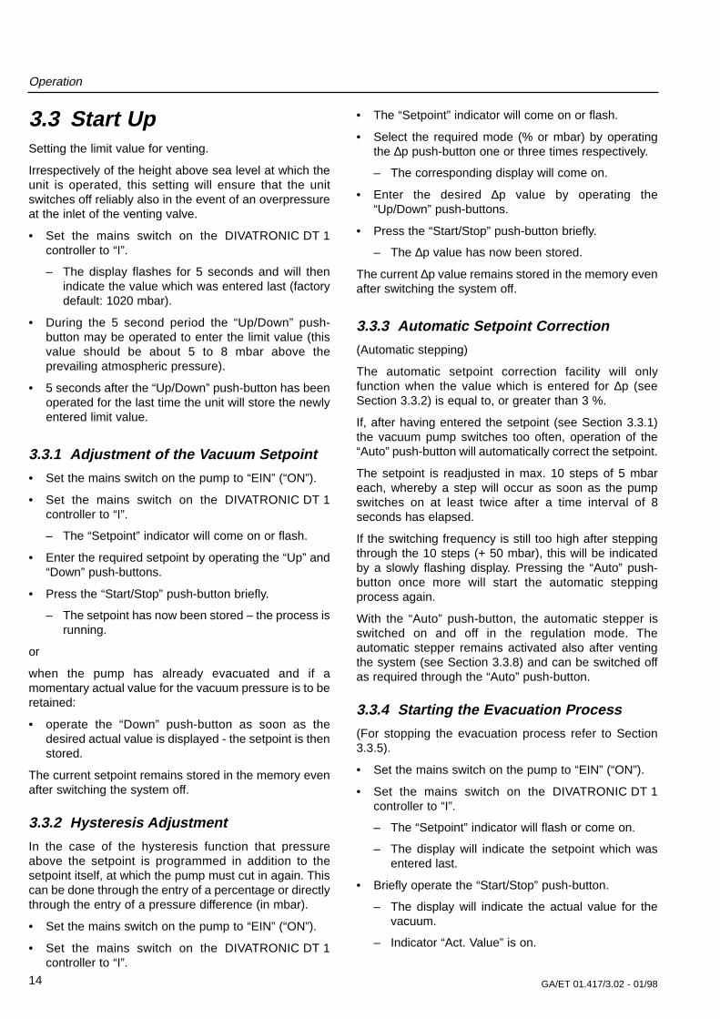
3.3 Start UpSetting the limit value for venting.
Irrespectively of the height above sea level at which theunit is operated, this setting will ensure that the unitswitches off reliably also in the event of an overpressureat the inlet of the venting valve.
• Set the mains switch on the DIVATRONIC DT 1controller to “I”.
– The display flashes for 5 seconds and will thenindicate the value which was entered last (factorydefault: 1020 mbar).
• During the 5 second period the “Up/Down” push-button may be operated to enter the limit value (thisvalue should be about 5 to 8 mbar above theprevailing atmospheric pressure).
• 5 seconds after the “Up/Down” push-button has beenoperated for the last time the unit will store the newlyentered limit value.
3.3.1 Adjustment of the Vacuum Setpoint
• Set the mains switch on the pump to “EIN” (“ON”).
• Set the mains switch on the DIVATRONIC DT 1controller to “I”.
– The “Setpoint” indicator will come on or flash.
• Enter the required setpoint by operating the “Up” and“Down” push-buttons.
• Press the “Start/Stop” push-button briefly.
– The setpoint has now been stored – the process isrunning.
or
when the pump has already evacuated and if amomentary actual value for the vacuum pressure is to beretained:
• operate the “Down” push-button as soon as thedesired actual value is displayed - the setpoint is thenstored.
The current setpoint remains stored in the memory evenafter switching the system off.
3.3.2 Hysteresis Adjustment
In the case of the hysteresis function that pressureabove the setpoint is programmed in addition to thesetpoint itself, at which the pump must cut in again. Thiscan be done through the entry of a percentage or directlythrough the entry of a pressure difference (in mbar).
• Set the mains switch on the pump to “EIN” (“ON”).
• Set the mains switch on the DIVATRONIC DT 1controller to “I”.
• The “Setpoint” indicator will come on or flash.
• Select the required mode (% or mbar) by operatingthe ∆p push-button one or three times respectively.
– The corresponding display will come on.
• Enter the desired ∆p value by operating the“Up/Down” push-buttons.
• Press the “Start/Stop” push-button briefly.
– The ∆p value has now been stored.
The current ∆p value remains stored in the memory evenafter switching the system off.
3.3.3 Automatic Setpoint Correction
(Automatic stepping)
The automatic setpoint correction facility will onlyfunction when the value which is entered for ∆p (seeSection 3.3.2) is equal to, or greater than 3 %.
If, after having entered the setpoint (see Section 3.3.1)the vacuum pump switches too often, operation of the“Auto” push-button will automatically correct the setpoint.
The setpoint is readjusted in max. 10 steps of 5 mbareach, whereby a step will occur as soon as the pumpswitches on at least twice after a time interval of 8seconds has elapsed.
If the switching frequency is still too high after steppingthrough the 10 steps (+ 50 mbar), this will be indicatedby a slowly flashing display. Pressing the “Auto” push-button once more will start the automatic steppingprocess again.
With the “Auto” push-button, the automatic stepper isswitched on and off in the regulation mode. Theautomatic stepper remains activated also after ventingthe system (see Section 3.3.8) and can be switched offas required through the “Auto” push-button.
3.3.4 Starting the Evacuation Process
(For stopping the evacuation process refer to Section3.3.5).
• Set the mains switch on the pump to “EIN” (“ON”).
• Set the mains switch on the DIVATRONIC DT 1controller to “I”.
– The “Setpoint” indicator will flash or come on.
– The display will indicate the setpoint which wasentered last.
• Briefly operate the “Start/Stop” push-button.
– The display will indicate the actual value for thevacuum.
– Indicator “Act. Value” is on.

GA/ET 01.417/3.02 - 01/98 15
Operation
– Indicator “Regulation Mode” is on.
– Pump starts up and keeps running until theentered setpoint has been reached.
3.3.5 Stopping the Evacuation Process
An evacuation process which is currently in progresstrying to attain the entered setpoint can be terminated atany time:
• Briefly operate the “Start/Stop” push-button.
– The display will indicate the setpoint.
– The “setpoint” indicator flashes.
3.3.6 Restart after Stopping a RunningEvacuation Process
• Briefly operate the “Start/Stop” push-button.
– The display will indicate the actual value for thevacuum.
– Indicator “Act. Value” is on.
– Indicator “Regulation Mode” is on.
3.3.7 Evacuation without Control forMaximum Vacuum (Drying Mode)
Running of the drying mode is recommended aftercompletion of the process in order to remove anycondensate which possibly may have collected in thediaphragm heads.
If a higher vacuum pressure is required than the vacuumpressure currently selected or when wanting to run thedrying mode:
• Briefly operate the “Start/Stop” push-button.
– The “setpoint” indicator flashes.
• Press the “Start/Stop” push-button until the“Regulation Mode” indicator is erased.
– Indicator “Act. Value” is on.
• Stop the evacuation process by operating the“Start/Stop” push-button briefly.
3.3.8 Venting of the System
If the vacuum system is to be vented or when wanting toapply inert gas:
• Press the “Start/Stop” push-button until the ventingvalve responds.
– Pump is not running.
– The display will continuously display the actualvalue of the vacuum.
– Indicator “Act. Value” is on.
– After pressure equalisation this display will
change to indicate the setpoint.
– The “Setpoint” indicator is on.
The pressure for the inert gas supply mustnot exceed an overpressure of 0.3 bar.
Option: Cooling water valve for the highperformance condenser
When interrupting the regulation mode of the DIVACsystem by operating the “Start/Stop” push-button on theDIVATRONIC DT 1 controller or when terminating thismode, the cooling water will normally continue to runthrough the high performance condenser. The flow of thecooling water may be stopped with the aid of a coolingwater valve.
When using a recirculating thermostat please observethe information provided in the Operating Instructions forthe particular recirculation thermostat.
Installation:
• Connect the cooling water valve to the water supply.
• Connect the signal cable from the cooling water valveto the socket “SOL. 1” on the DIVATRONIC DT 1controller.
• Cooling water valves are available from us uponrequest.
Caution
Fig. 13 Connection of the inert gas to the valve of the

GA/ET 01.417/3.02 - 01/9816
Operation
Within the system only such gases may bepumped together which can be mixedwithout problems.
The baseplate (see Section 3.2.1).
The separator (see Section 3.2.2).
The high performance condenser (see Section 3.2.2).
The control unit (see Section 3.2.3).
The DIVATRONIC DT 1 controller (see Section 3.2.3).
In the case of the pump system with two DIVATRONICDT 1 vacuum controllers, two different processes can becontrolled and monitored simultaneously andindependently of each other. This is possible through twovacuum valves which are each controlled by aDIVATRONIC DT 1 vacuum controller.
Operation of each DIVATRONIC DT 1 controller doesnot differ from the operation of a single DIVATRONIC DT1 controller (see Section 3.2.3). Each DIVATRONIC DT1 controller operates independently of the othercontroller and all settings are separate.
As soon as the setpoint on one DIVATRONIC DT 1controller has been attained, the valve which iscontrolled by that controller closes, whereby the pumpcontinues the evacuation process until the setpointwhich has been entered on the second DIVATRONIC DT1 controller is attained. The second vacuum valvecloses, the pump is switched off and the pump reliefvalve opens.
After the two vacuum pressures have decreased, thepump will cut in as soon as one of the hysteresis rangeshas been exceeded.
Otherwise operation is the same as for the systemswhich are equipped with only one DIVATRONIC DT 1controller (SC systems) see Section 3.2.3 andsubsequent sections.
Warning
DIVAC
Fig. 14 Hose connections on the DIVAC SCC system
Hose No. Hose length, approx. Inside diameter of the hose
1 320 mm 10 mm
2 260 mm 10 mm
3 and 4 120 mm each 10 mm
5 135 mm 10 mm
6 175 mm 10 mm
7 350 mm 10 mm
8 220 mm 10 mm
Cooling watersupply / drain
Pump reliefvalve
Vacuum valve 1 Vacuum valve 2
2
1
3
4
87
5
6
to the wastedisposal unit
From vacuumchamber 1 or 2
3.4 Operation with Baseplate, Separator, High PerformanceCondenser, Control Unit and two DIVATRONIC DT 1 (SCC)

GA/ET 01.417/3.02 - 01/98 17
Operation
3.4.1 Upgrading of existing DIVACsystems (SH/SC to SC/SCC) withDIVATRONIC modules (see Section5.3)
Described in the following are the necessary steps forretrofitting or upgrading a DIVAC system to the fullyfeatured version beginning with the following initialsituations:
• System with baseplate, separator and condenseralready present: upgrading with installationaccessories. Corresponds to the DIVAC SH system, see Section3.4.1.
• System with baseplate, separator, condenser, controlunit, support post and DIVATRONIC DT 1 controlleralready present: upgrading with installationaccessories.Corresponds to the DIVAC SC system, see Section3.4.2.
3.4.1.1 System with already present Baseplate, Separator and Condenser (SH System)
For this please also refer to Fig. 1.
• Required tools:
1 hex. socket screw key 4 mm and 5 mm
• Shut down the pump and disconnect from the mains(see Section 3.6).
You must pull the mains plug.
• Both DIVATRONIC DT 1 controllers, includingventing valves, the pump relief valve as well as thetwo vacuum valves are supplied already installed onthe support post.
• Attach the control unit to the left hand side of thebaseplate.
– Insert the two tightening nuts which have beenfitted to the control unit into the slot pointing to theside by pushing the control unit.
– Tighten by tightening the two hex. socket screwsat the base of the control unit.
• Installation of the support post together withDIVATRONIC DT 1 controllers and valves
– Insert the support post (attachment section) intothe slot pointing up on the baseplate (foralignment see Fig. 5).
– Tighten the support post by tightening the hex.socket screw located in the slot at the supportpost.
• For hose connections refer to Fig. 14.
Use only such a hose material which is ableto resist the kind of media used.
• Electrical wiring and connections.
– Controller DIVATRONIC DT 1 with control unit:
Connect DIVATRONIC DT 1 controller connection“SOL.2” to the connection “V.IN. 1” or “V.IN. 2” onthe control unit using the supplied cables (see Fig.15).
– Plug the mains plug of the DIVATRONIC DT 1controller into the corresponding socket on thecontrol unit (see Fig. 10 or 15).
– Vacuum valves with control unit:
Insert the two plugs of the vacuum valves into thesockets “SOL. 1” and “SOL. 2” on the control unit(see Fig. 15).
– Pump relief valve with control unit:
Insert the plug on the cable for the pump reliefvalve into socket “PRV” on the control unit (seeFig. 15).
– Pump with control unit:
Insert the mains connector of the pump into themarked mains socket with protective groundconductor on the control unit (see also Fig. 10).
For proper operation of the entire system itis necessary that the mains connection ofthe pump be provided through this socketwith protective ground conductor.
– Connection of the control unit to the mains:
Insert the mains plug with protective groundconductor on the mains cable of the control unitinto a properly installed mains socket withconnected protective ground conductor.
3.4.1.2 System with already present Baseplate, Separator, Condenser, Control Unit, SupportPost and one DIVATRONIC DT 1 controller (SC Systems)
For this refer to Fig. 1.
• Required tools:
1 hex. socket wrench 4 mm
Warning
Caution
Caution

GA/ET 01.417/3.02 - 01/9818
Operation
Disassembly steps
• Shut down the pump and disconnect the control unitfrom the mains (see Section 3.6).
You must pull the mains plug.
• Disconnect all plugs from their sockets or mainssockets on the control unit.
• Disconnect all hose connections at the pump reliefvalve as well as on the venting valve of theDIVATRONIC DT 1 controller.
• Remove the DIVATRONIC DT 1 controller from thesupport post after loosening the clamped connection.
• Remove the cross bar from the support post afterloosening the clamped connection.
• Remove the support post from the baseplate:
– Release the clamped connection by loosening thehex. socket screw at the support post.
– Pull the support post out of the slot in thebaseplate.
• The second DIVATRONIC DT 1 controller withventing valve is supplied already fitted to the newsupport post (410 mm long).
• Attach the controller which has previously been usedto the support post too: insert into the slot providedfor this purpose on the DIVATRONIC DT 1 controller(its tightening nut) and fix in place by tightening thehex. socket screw.
• Insert the support post (its attachment section) intothe slot on the baseplate at the side which faces up.
• Fix the support post in place by tightening the hex.socket screw at the support post in the slot.
• Attach the cross bar to the support post again.
• Insert the holder for the solenoid valve (including thesolenoid valve itself) into the cross slot on the supportpost and fix it in place through the clampedconnection.
• Provide the hose connections according to Fig. 14.
Fig. 15 Electrical connection on the DIVAC system SCC 0.6 L - 1.2 L - 2.2 L (EURO Version)
Control unit
DIVATRONICDT 1
controller 1
Mains socket with protectiveground for the vacuum pump
Key to Fig. 151 Pump relief valve2 Connection “SOL. 2” on DIVATRONIC DT 1 controller 13 Connection “SOL. 2” on DIVATRONIC DT 1 controller 24 Connection “PRV” on the control unit5 Connection “V.IN. 2” on the control unit6 Connection “V.IN. 1” on the control unit7 Connection “SOL. 2” on the control unit8 Connection “SOL. 1” on the control unit9 Mains socket with protective ground for controller 210 Mains socket with protective ground for controller 111 Mains connection
Vacuumvalve 1
Vacuumvalve 2
1
2
3
4567891011
Warning
DIVATRONICDT 1
controller 2
GA/ET 01.417/3.02 - 01/98 19
Operation
Use only such a hose material which is ableto resist the kind of media used.
• Provide the electrical connections (as described inSection 3.4.1).
The following applies equally to Sections 3.4.1 and3.4.2:
Before starting the pump system check the following:
• all clamped connections for tightness,
• all hose connections as to whether they areconnected at the right places,
• all wiring as to whether it is connected at the rightplaces.
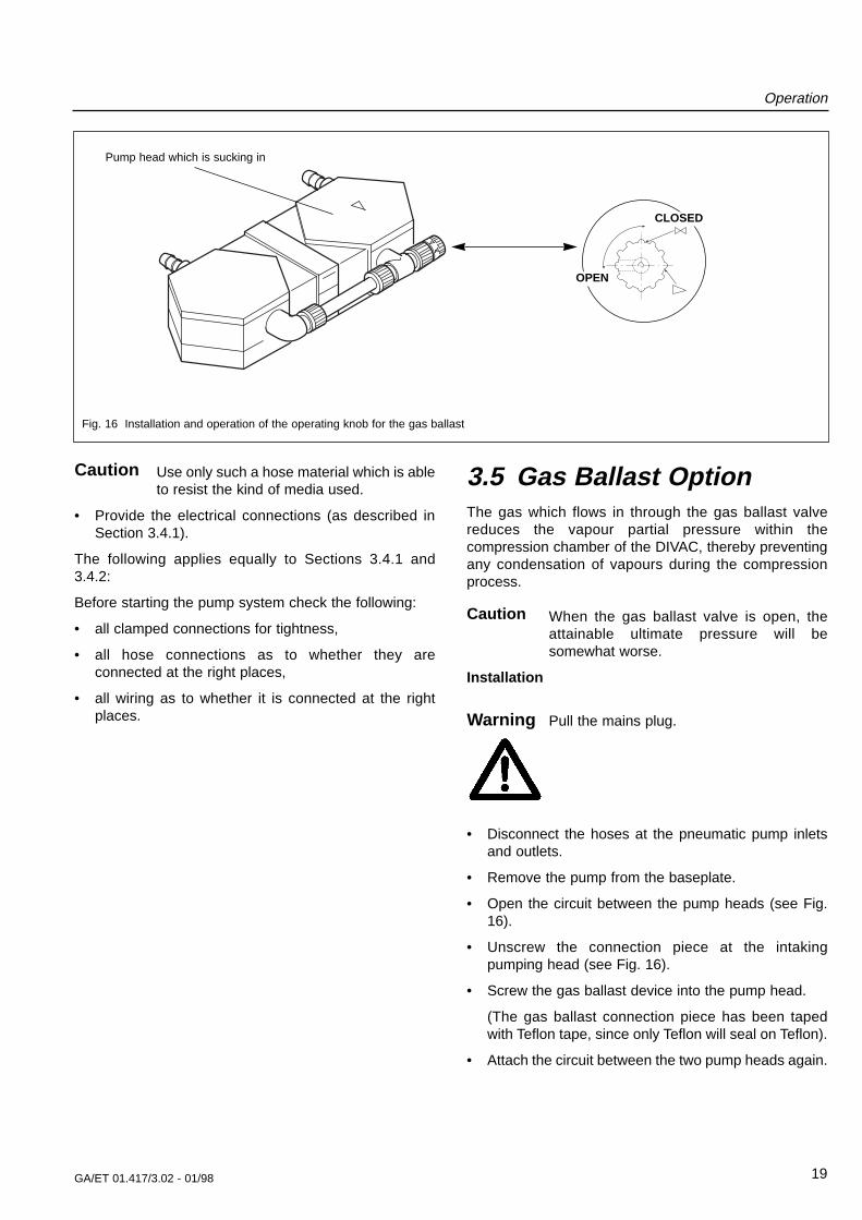
3.5 Gas Ballast OptionThe gas which flows in through the gas ballast valvereduces the vapour partial pressure within thecompression chamber of the DIVAC, thereby preventingany condensation of vapours during the compressionprocess.
When the gas ballast valve is open, theattainable ultimate pressure will besomewhat worse.
Installation
Pull the mains plug.
• Disconnect the hoses at the pneumatic pump inletsand outlets.
• Remove the pump from the baseplate.
• Open the circuit between the pump heads (see Fig.16).
• Unscrew the connection piece at the intakingpumping head (see Fig. 16).
• Screw the gas ballast device into the pump head.
(The gas ballast connection piece has been tapedwith Teflon tape, since only Teflon will seal on Teflon).
• Attach the circuit between the two pump heads again.
Caution
Caution
Fig. 16 Installation and operation of the operating knob for the gas ballast
CLOSED
OPEN
Pump head which is sucking in
Warning
GA/ET 01.417/3.02 - 01/9820
Operation
3.6 Shut Down• Clean the vessels.
• Purge the fully installed hose system on the pumpwith air for about 5 minutes at full throughput.
• Pull the mains plug.
3.7 Troubleshooting3.7.1 System without DIVATRONIC DT 1
Controller (SH/SR Systems)
• A sufficient vacuum is not attained.
Possible causes:
– Leaky hoses connections.
– Condensate in the pump head (separate thesource of the condensate from the pump, run thedrying mode according to Section 3.3.7).
– Diaphragm and /or valve disk are worn out. Thevalve disk or the diaphragm will have to beexchanged (see Section 3.8).
– After having exchanged diaphragms, valve discsand or gaskets: see description of Section 3.8.
• Pump has been switched on, but it is not running,mains switch does also not come on.
Possible causes:
– The pump has not been connected to the mains.
– No mains voltage is present.
– Fuse for the pump has blown.
Leave troubleshooting to suitably trainedpersonnel. Disconnect the pump from the mains bypulling the mains plug.
– After loosening the marked lid under the pump,the fuse will be accessible.
• Pump has been switched on, but it is not running,mains switch is on.
Possible cause:
– The overtemperature switch on the pump hasresponded because of overheating (pull the mainsplug, let the pump cool down, determine the causefor overheating and remove the cause).
3.7.2 System with one DIVATRONIC DT 1Controller (SC Systems)
• A sufficient vacuum is not attained.
Possible causes: same as for systems withoutDIVATRONIC DT 1 controller (see Section 3.7.1).
Possible additional causes:
Solid objects in the relief valve of the pump.
• DIVATRONIC DT 1 controller has been switched onand set to the “Regulation mode”, setpoint is notattained, pump is not running, light in the mainsswitch of the pump is not on.
Possible causes:
– Pump has not been switched on,
– Incorrect wiring,
– Fuse of the pump has blown (see Section 3.7.1,system without DIVATRONIC DT 1 controller).
• DIVATRONIC DT 1 controller has been switched onand set to the “Regulation mode”, setpoint is notattained, pump is not running. Light in the mainsswitch is on.
Possible cause:
– The overtemperature switch on the pump hasresponded because of overheating.
(Pull the mains plug of the pump, let the pumpcool down, determine the cause for overheatingand remove the cause).
• DIVATRONIC DT 1 controller has been switched on,nothing is displayed on the LCD display.
Possible causes:
– Mains switch of the DIVATRONIC DT 1 controllerhas been plugged into the mains socket on thepump’s control unit.
– Fuse in the DIVATRONIC DT 1 controller hasblown.
(This fuse is located above the On/Off switch ofthe DIVATRONIC DT 1 controller)
– Fuse in the control unit has blown.
(These fuses are located on the face side of thecontrol unit directly under the mains connection).
• DIVATRONIC DT 1 controller indicates unrealisticvalues.
Possible causes:
– Factory alignment for the pressure as changed(contact Leybold).
– Sensor is faulty (contact Leybold).
Warning

GA/ET 01.417/3.02 - 01/98 21
Operation
3.7.3 System with two DIVATRONIC DT 1Controllers (SCC Systems)
• See system with one DIVATRONIC DT 1 controller(Section 3.7.2)
• System is not working although one DIVATRONIC DT1 controller (or both DIVATRONIC DT 1 controllers)has (have) been set to the “Regulation mode”.
Possible cause:
– The signal cables of the two DIVATRONIC DT 1controllers or the vacuum valves have not beenconnected properly (the connectors betweencontroller 1 and 2 or those for the vacuum valves1 and 2 have been interchanged).
3.8 Exchanging Diaphragmsand Valves Plates
The diaphragms should always be exchanged on bothpump heads together. When exchanging thediaphragms, the valve plates of the pump should also beexchanged. If both pump heads are not maintained inthe same way, it can not be guaranteed that the pumpwill meet its nominal specifications also after havingcompleted the maintenance work.
Required tools / materials:
• Spare parts kit (see Section 6).
• Phillips screwdriver No. 2.
Preparations
• Shut the pump down, (see Section 3.6), and separatethe pump from the mains (pull the mains plug).
• Disconnect the hoses at the pneumatic pump inletsand outlets.
• Remove the pump from the baseplate, if required.
Disassemble the pump head
• Open the circuit between the pump heads.
• Loosen the 6 outer screws at each of the two pumpheads.
• Carefully remove the pump heads.
Exchanging the diaphragm
• Because access to the diaphragms is easier, takehold of the diaphragm and carefully turn it out in theanti-clockwise direction (thread).
• Place the same number of washers found on thediaphragm thread onto the thread of the newdiaphragm.
• If required, bring the second diaphragm to its upperreturn point by pressing on to the connecting rodwhich is now accessible.
• Unscrew the second diaphragm as described above.
• Screw the new diaphragm in.
• Press the lip of the diaphragm down around thecircumference.
Fig. 17 Section through the pump head

GA/ET 01.417/3.02 - 01/9822
Operation
Exchanging the valve plate
• Loosen the single screw at the center of the lid for thepump head.
• Carefully remove this lid; gasket and valve plate arenow accessible.
• Remove the old gasket and the old valve plate.
• Carefully fit the new gasket and the new valve plate.
• Properly fit the lid for the pump head.
• Tighten the screw at the center of the lid until thehead of the screw is flush with the lid. Then tightenthe screw further by half a turn.
Installing the pump head
• Fit the pump heads to the pump housing (observe theguide pin) and tighten crosswise using moderateforce.
• Install the circuit between the pump heads.
• Place the pump on the baseplate (if present).
• Provide the hose connections again.
If, after having exchanged the diaphragm, the desiredvacuum is not attained:
– Check whether or not the necessary number ofwashers have been fitted on to the thread of thediaphragm.
– Check the connection between the pump headsand the hose connections for the existence of anyleaks.
– Possibly the screws of one or both pump headshave not been sufficiently tightened (tightenfurther crosswise).
Tighten the bolts for lids of the heads (19/3)until encountering some resistance andthen tighten by a further 1/2 turn. Do notbolt down tightly!
Fig. 18 Gasket and valve plate
Caution

GA/ET 01.417/3.02 - 01/98 23
Technical Data / Ordering Information
DIVAC 0.6 L DIVAC 1.2 L DIVAC 2.2 L
DIVAC 0.6 L DIVAC 1.2 L DIVAC 2.2 L
Diaphragm vacuum pump 230 V, 50 Hzwith 2.3 m long mains cord and plug
Diaphragm vacuum pump 230 V, 50 HzVersion for Switzerland
Diaphragm vacuum pump 240 V, 50 HzVersion for Great Britain
Diaphragm vacuum pump 100 V, 50/60 Hzwith 2.3 m long mains cord and NEMA plug
Diaphragm vacuum pump 115 V, 60 Hzwith 2.3 m long mains cord and NEMA plug
Spare parts kit consisting of:2 diaphragms, 4 gaskets, 4 valve plates
Components for the modular DIVAC-System:Basepanel for system mountSeparatorHigh performance condenserGas ballast valveVacuum controller DIVATRONIC DT 1
230 V, 50 HzVacuum controller DIVATRONIC DT 1
100 - 115 V, 50/60 Hz
Cat. No. 135 00
Cat. No. 135 04
Cat. No. 135 01
Cat. No. 135 02
Cat. No. 135 03
Cat. No. 135 23
Cat. No. 135 18Cat. No. 135 20Cat. No. 135 21Cat. No. 135 26Cat. No. 161 17
Cat. No. 89 617
Cat. No. 135 06
Cat. No. 135 10
Cat. No. 135 07
Cat. No. 135 08
Cat. No. 135 09
Cat. No. 135 24
Cat. No. 135 18Cat. No. 135 20Cat. No. 135 21Cat. No. 135 27Cat. No. 161 17
Cat. No. 89 617
Cat.-No.. 135 12
Cat.-No.. 135 16
Cat.-No.. 135 13
Cat.-No.. 135 14
Cat.-No.. 135 15
Cat.-No.. 135 25
Cat.-No.. 135 19Cat.-No.. 135 20Cat.-No.. 135 21Cat.-No.. 135 27Cat.-No.. 161 17
Cat.-No.. 89 617
Pumping speed, max. m3 · h-1
Ultimate pressure mbar
Max. exhaust overpressure bar
Permissible ambient temperature °C
Permissible temperature for the pumped gas °C
Motor power VA
Protection IP
Weight kg
Dimensions (L x W x H) mm
0.6
8
1
+5 to +40
+5 to +40
90
44
6.9
275 x 141 x 183
1.2
8
1
+5 to +40
+5 to +40
120
44
9.3
310 x 157 x 202
2.2
8
1
+5 to +40
+5 to +40
200
44
12.6
334 x 170 x 221
4 Technical Data
5 Ordering Information5.1 DIVAC Pump System
GA/ET 01.417/3.02 - 01/9824
Ordering Information
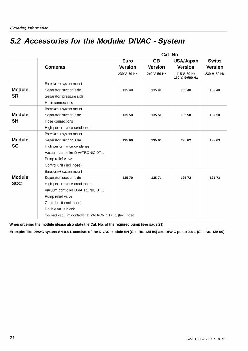
5.2 Accessories for the Modular DIVAC - System
When ordering the module please also state the Cat. No. of the required pump (see page 23).
Example: The DIVAC system SH 0.6 L consists of the DIVAC module SH (Cat. No. 135 50) and DIVAC pump 0.6 L (Cat. No. 135 00)
Cat. No.Euro GB USA/Japan Swiss
Contents Version Version Version Version230 V, 50 Hz 240 V, 50 Hz 115 V, 60 Hz 230 V, 50 Hz
100 V, 50/60 Hz
Baseplate + system mount
Module Separator, suction side 135 40 135 40 135 40 135 40
SR Separator, pressure side
Hose connections
Baseplate + system mount
Module Separator, suction side 135 50 135 50 135 50 135 50
SH Hose connections
High performance condenser
Baseplate + system mount
Module Separator, suction side 135 60 135 61 135 62 135 63
SC High performance condenser
Vacuum controller DIVATRONIC DT 1
Pump relief valve
Control unit (incl. hose)
Baseplate + system mount
Module Separator, suction side 135 70 135 71 135 72 135 73
SCC High performance condenser
Vacuum controller DIVATRONIC DT 1
Pump relief valve
Control unit (incl. hose)
Double valve block
Second vacuum controller DIVATRONIC DT 1 (Incl. hose)
Ordering Information
GA/ET 01.417/3.02 - 01/98 25
Cat. No.Euro GB USA/Japan Swiss
Contents Version Version Version Version230 V, 50 Hz 240 V, 50 Hz 115 V, 60 Hz 230 V, 50 Hz
100 V, 50/60 Hz
Vacuum controller DIVATRONIC DT1
DIVATRONIC Connecting piece (Tee) 161 17 – 869 17 –
DT1 with hose nozzle
Spare fuse
Vacuum controller DIVATRONIC DT1
Module Support post 135 80 135 81 135 82 135 83
DIVATRONIC Pump valve (24 V)
A Control unit
incl. all cables
Second vacuum controller
Module DIVATRONIC DT1 135 85 135 85 135 87 135 85
DIVATRONIC Support post
B Double valve (24 V)
incl. all cables
2 vacuum controllers DIVATRONIC DT1
Module Support post 135 90 135 91 135 92 135 93
DIVATRONIC Pump and double valve (24 V)
A/B Control unit
incl. all cables
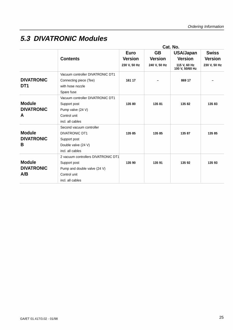
5.3 DIVATRONIC Modules

GA/ET 01.417/3.02 - 01/9826
Spare Parts
6 Spare Parts
ACDIVACDIV
3 4 3
Fig. 19 Spare parts
1
8
2
5
7 for DIVAC 2.2 L only
6

GA/ET 01.417/3.02 - 01/98 27
Spare Parts
1 1 Lid A - DIVAC 0.6 L PTFE 200 65 009
1 1 Lid A - DIVAC 1.2 L PTFE 200 65 011
1 1 Lid A - DIVAC 2.2 L PTFE 200 65 013
2 1 Lid B - DIVAC 0.6 L PTFE 200 65 010
2 1 Lid B - DIVAC 1.2 L PTFE 200 65 012
2 1 Lid B - DIVAC 2.2 L PTFE 200 65 014
3 1 Set of bolts for one head includes spring washers 200 65 018
3 1 Set of bolts for one head includes spring washers 200 65 019
3 1 Set of bolts for one head includes spring washers 200 65 020
4 1 Set of hose nozzles DIVAC 0.6 L 200 65 005
4 1 Set of hose nozzles DIVAC 1.2 L 200 65 006
4 1 Set of hose nozzles DIVAC 2.2 L 200 65 007
4a 1 Hose nipple NPT 1/8” 200 65 025
4a 1 1 Hose nipple NPT 1/4” 200 65 026
5 1 Intermediate panel PTFE 200 65 015
5 1 Intermediate panel PTFE 200 65 016
5 1 Intermediate panel PTFE 200 65 017
6 1 1 Silencing kit DIVAC 0.6 L + 1.2 L included with item 8 ---
7 1 Silencing kit DIVAC 2.2 L 200 65 001
8 1 Maintenance kit - DIVAC 0.6 L *) 135 23*)
8 1 Maintenance kit - DIVAC 1.2 L *) 135 24*)
8 1 Maintenance kit - DIVAC 2.2 L *) 135 25*)
*) contains all parts
required for maintenance
of the pump head.
(2 diaphragms, 4 gaskets, 4 valve
plates and the silencing parts for the
DIVAC 0.6 L and DIVAC 1.2 L)
--- 1 1 1 Norprene hose 1 m 200 65 002
--- 1 1 1 Vacuum valve, single see Fig. 1, item 16 200 65 003
--- 1 1 1 Vacuum valve, double see Fig. 1, item 15 200 65 004
Item Designation Ref. No.Quantity Remarks/
materialDIVAC0.6 L
DIVAC1.2 L
DIVAC2.2 L
GA/ET 01.417/3.02 - 01/9828
S AM P
L E
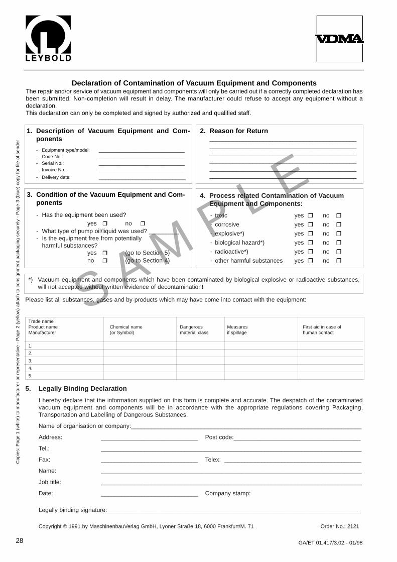
Declaration of Contamination of Vacuum Equipment and ComponentsThe repair and/or service of vacuum equipment and components will only be carried out if a correctly completed declaration hasbeen submitted. Non-completion will result in delay. The manufacturer could refuse to accept any equipment without adeclaration.This declaration can only be completed and signed by authorized and qualified staff.
1. Description of Vacuum Equipment and Com-ponents
- Equipment type/model: _________________________________- Code No.: _________________________________- Serial No.: _________________________________- Invoice No.: _________________________________
- Delivery date: __________________________
2. Reason for Return________________________________________________________________________________________________________________________________________________________________________________________________________________________________________________________________________
3. Condition of the Vacuum Equipment and Com-ponents
- Has the equipment been used?yes ❒ no ❒
- What type of pump oil/liquid was used? _________- Is the equipment free from potentially
harmful substances?yes ❒ (go to Section 5)no ❒ (go to Section 4)
4. Process related Contamination of Vacuum Equipment and Components:
- toxic yes ❒ no ❒
- corrosive yes ❒ no ❒
- explosive*) yes ❒ no ❒
- biological hazard*) yes ❒ no ❒
- radioactive*) yes ❒ no ❒
- other harmful substances yes ❒ no ❒
*) Vacuum equipment and components which have been contaminated by biological explosive or radioactive substances,will not accepted without written evidence of decontamination!
Please list all substances, gases and by-products which may have come into contact with the equipment:
Trade nameProduct name Chemical name Dangerous Measures First aid in case ofManufacturer (or Symbol) material class if spillage human contact
1.
2.
3.
4.
5.
Cop
ies:
Pag
e 1
(whi
te)
to m
anuf
actu
rer
or r
epre
sent
ativ
e -
Pag
e 2
(yel
low
) at
tach
to
cons
ignm
ent
pack
agin
g se
cure
ly -
Pag
e 3
(blu
e) c
opy
for
file
of s
ende
r
5. Legally Binding Declaration
I hereby declare that the information supplied on this form is complete and accurate. The despatch of the contaminatedvacuum equipment and components will be in accordance with the appropriate regulations covering Packaging,Transportation and Labelling of Dangerous Substances.
Name of organisation or company:_____________________________________________________________________
Address: _____________________________ Post code:______________________________________
Tel.: ______________________________________________________________________________
Fax: _____________________________ Telex: _________________________________________
Name: ______________________________________________________________________________
Job title: ______________________________________________________________________________
Date: _____________________________ Company stamp:
Legally binding signature:____________________________________________________________________________
Copyright © 1991 by MaschinenbauVerlag GmbH, Lyoner Straße 18, 6000 Frankfurt/M. 71 Order No.: 2121

GA/ET 01.417/3.02 - 01/98 29
We - LEYBOLD Vacuum GmbH - herewith declare thatthe products defined below meet the basic requirementsregarding safety and health of the relevant EC directivesby design, type and versions which are brought intocirculation by us.
In case of any product changes made without ourapproval, this declaration will be void.
Designation of the products: Diaphragm pump
Types: DIVAC 0.6 L; 1.2 L; 2.2 L
Cat. Nos.:
135 00; 135 01; 135 02; 135 03; 135 04;
135 06; 135 07; 135 08; 135 09; 135 10;
135 12; 135 13; 135 14; 135 15; 135 16;
135 40; 135 50;
135 60; 135 61; 135 62; 135 63;
135 70; 135 71; 135 72; 135 73;
135 80; 135 81; 135 82; 135 83;
135 85; 135 87;
135 90; 135 91; 135 92; 135 93
LHK
.GV.
0049
.01.
09.9
5
EEC Declaration of Conformity
The products conform to the following directives:
• EEC Directive on EMI (89/336/EWG)
• EEC Directive on Low-Voltages (73/23/EWG)
Applied harmonised standards:
• EN 292 Part 1 and Part 2
• EN 294
• EN 61 010 Part 1
• EN 50 081 Part 1
• EN 50 082 Part 1
• EN 50 014
• EN 60 555 Part 2 and 3
Cologne, September 1, 1995
—————————————————————Plingen, Business Area Manager Forevacuum pumps
Cologne, September 1, 1995
—————————————————————Frings, Design Department Manager Forevacuum pumps

We reserve the right to alter the design or any data givenin these Operating Instructions. The illustrations are notbinding.
1.80
.8.6
37.0
2
OF
/RS
P01
.98
Prin
ted
in G
erm
any
on c
hlor
ine-
free
ble
ache
d pa
per
GA/ET 01.417/3.02 - 01/98
LEYBOLD VAKUUM GmbHBonner Strasse 498 (Bayenthal)D-50968 CologneTel.: + 49 (221) 347-0Fax: + 49 (221) 347-1250http://www.leyboldvac.dee-mail:[email protected]