Vacuum Science and Technology for Accelerator Vacuum Systems · Screw Pumps Screw pumps are dry...
50
Yulin Li and Xianghong Liu Cornell University, Ithaca, NY Vacuum Science and Technology for Accelerator Vacuum Systems
Transcript of Vacuum Science and Technology for Accelerator Vacuum Systems · Screw Pumps Screw pumps are dry...

Yulin Li and Xianghong Liu Cornell University, Ithaca, NY
Vacuum Science and Technology for Accelerator
Vacuum Systems

Vacuum Fundamentals
Sources of Gases
Vacuum Instrumentation
Vacuum Pumps Vacuum Components/Hardware
Vacuum Systems Engineering
Accelerator Vacuum Considerations, etc.
Table of Contents
2

SESSION 4: VACUUM PUMPS
• Category of Vacuum Pumps • Displacement Pumps (Sec. 4.1) • Capture Pumps (Sec. 4.2-4.4) • Accelerator Pumping Considerations
3

January 19-23 2015 4
Two Major Categories of Vacuum Pumps
Displacement Pumps Capture Pumps Pumping by displacing gas to outside
of the vacuum envelope, via volume exchange, or momentum transfer to compress and to convey gaseous molecules to the exhaust
Primary pumps can start from atm. Pressure.
No capacity limit
Moving parts may fail in continuous operations. Potential contamination.
Pumping by storing, or capturing gas molecules through chemi- or/and physi-sorption onto the pumping elements
No moving parts, clean
Can’t (effectively) operate at high pressure
Limited pumping capacity
Based on how the gases are removed from gas phase

5
Fundamental Pump Parameters Pumping Speed
Working Pressure Range and Ultimate Pressure
Pumping Capacity
Pumping speed of a pump is the volumetric rate at which gas is transported across the pump inlet port.
It has a dimension of volume per unit time. Commonly used are: m3/s, CFM, m3/h, L/s
Pumping speed is usually pressure dependent, and gas dependent.
Every pump has a finite range of pressure in which it performs effectively in removing gases.
Ultimate pressure is the lowest pressure a pump can achieve with inlet blanked off.
Most capture pumps have finite pumping capacity, which measures a mount of gases it can capture either (1) before a regeneration is needed, or (2) a pump has to be replaced
January 19-23 2015

January 19-23 2015 6
Measuring Pumping Speed

7
Pumping Speed Measurement In most applications, the pumping speed information
supplied by the pump manufacturers is sufficient.
However, there are needs for measuring pumping speed of a pump for reasons such as: To verify pumping performance, after a pump rebuild or recondition. To measure pumping speed for a specific gas To measure pumping speed at specific conditions (different operation voltages, temperature, magnetic environment, etc.)
Pumping speed is defined as: S = Q/Pinlet . So both the throughput (Q) and pump inlet pressure (Pinlet) need to independently measured in pumping speed measurements.
There are two AVS recommended methods of pumping speed measurement: the flow-meter method and the conductance (orifice) method.
January 19-23 2015

8
Pumping Speed Measurement – Flow-Meter Dome
Gas Inlet Q
Gauge P
From: M. H. Hablanian, J. Vac. Sci. Technol. A5, 1987, p.2552
Gas is introduced into the test dome with a known rate, Q
Q is controlled either with a flow-meter (at high loads), or using a calibrated leak.
S = Q / (P-P0), P0 is the base pressure.
This is mostly used for primary pumps
January 19-23 2015

9
Pumping Speed Measurement – Orifice Dome
From: M. H. Hablanian, J. Vac. Sci. Technol. A5, 1987, p.2552
Gas Inlet Q
P1
P2 Orifice
An orifice with defined geometry defines the flow rate.
Q = Corifice x (∆P1 - ∆P2)
S = Q / ∆P2
This is mostly used for HV and UHV pumps. No need for calibrated flow rate control.
January 19-23 2015

10
Flow rates: 5 sccm ~ 10 slm (N2 equivalent)
Precision: 0.1% ~ 1% F.S.
Flow Control – Flow meters
January 19-23 2015
11
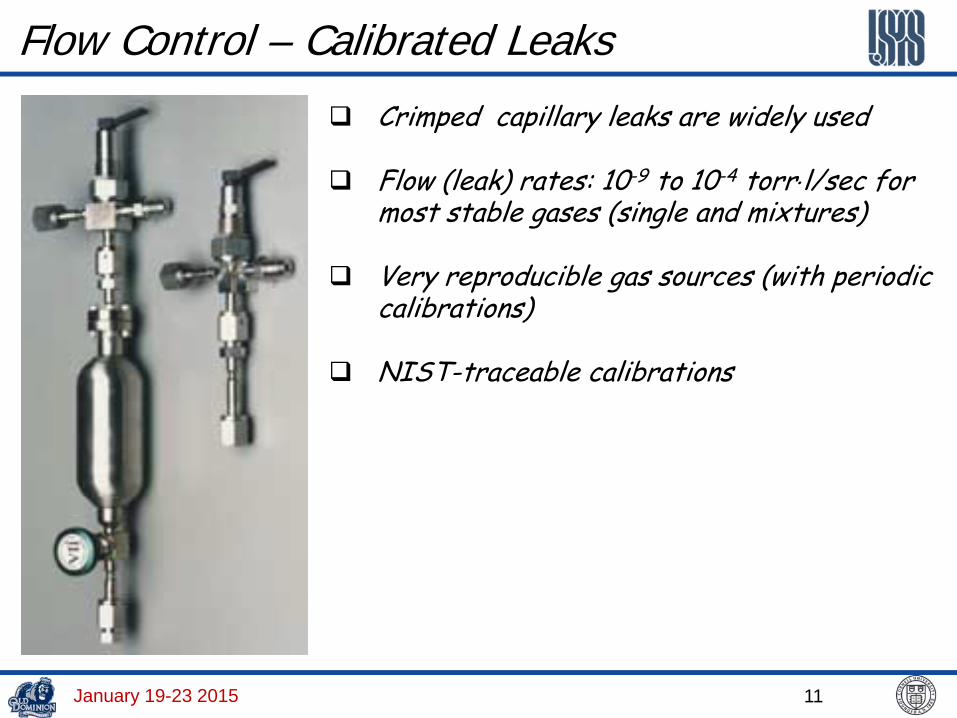
Flow Control – Calibrated Leaks
Crimped capillary leaks are widely used
Flow (leak) rates: 10-9 to 10-4 torr⋅l/sec for most stable gases (single and mixtures)
Very reproducible gas sources (with periodic calibrations)
NIST-traceable calibrations
January 19-23 2015

12
Flow Control – Variable Leak Valves
January 19-23 2015
13
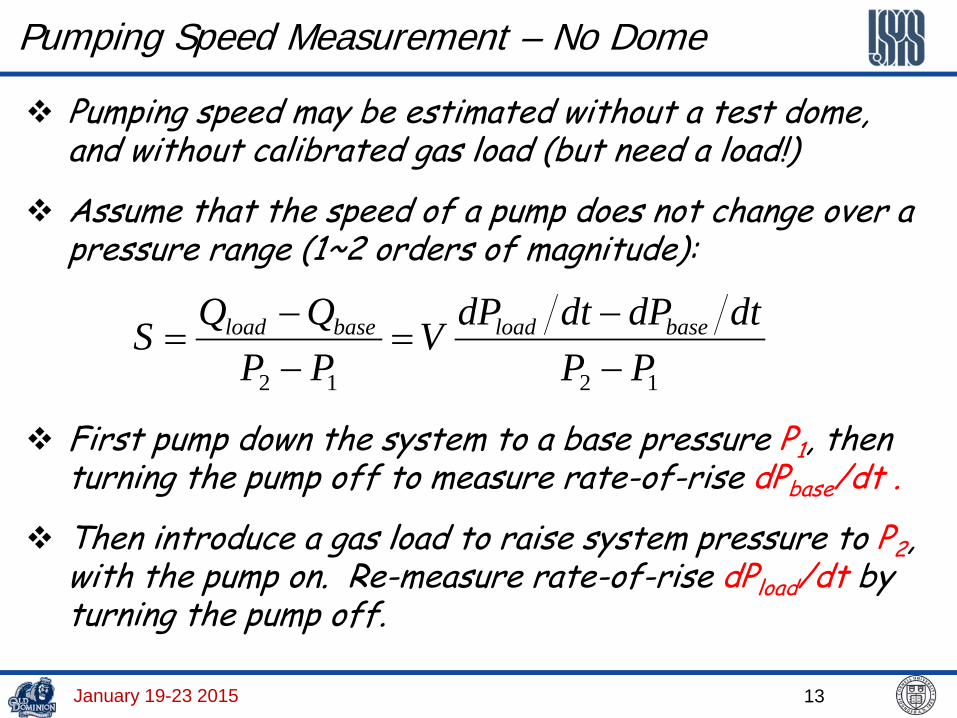
Pumping Speed Measurement – No Dome
Pumping speed may be estimated without a test dome, and without calibrated gas load (but need a load!)
Assume that the speed of a pump does not change over a pressure range (1~2 orders of magnitude):
1212 PPdtdPdtdPV
PPQQS baseloadbaseload
−−
=−−
=
First pump down the system to a base pressure P1, then turning the pump off to measure rate-of-rise dPbase/dt .
Then introduce a gas load to raise system pressure to P2, with the pump on. Re-measure rate-of-rise dPload/dt by turning the pump off.
January 19-23 2015

January 19-23 2015 14
Displacement Pumps

15
Displacement Pumps
Based on working pressure ranges
Primary Pumps HV-UHV Pumps
Oil-sealed or “Wet” Pumps
Dry Pumps
Rotary vane pumps Piston pumps Roots pumps
Diaphragm pumps Scroll pumps Screw pumps
Diffusion Pumps
Turbo-molecular pumps
January 19-23 2015

16
Primary Pumps
Type Advantages Disadvantages
Rotary Vane Low Ultimate Pressure Low Cost Reliable
Source of Backstreaming Oil & Hazardous Waste
Rotary Piston High Pumping Speed Low Cost
Noisy Source of Vibration
Scroll Clean Low “clean” Ultimate Pressure
Permeable to light gases Clean applications only
Diaphragm Quiet Easy to work on
Low Pumping Speed High Ultimate Pressure Requires frequent servicing
Roots Blower No (Low) Backstreaming Low Ultimate Pressure
Expensive Requires frequent servicing Requires purge gas
Screw Pump Handle high displacement rate Work with condensable gases/vapors Quiet operation
Expensive Heavy
January 19-23 2015

17
Rotary Vane Mechanical Pumps
January 19-23 2015

18
Rotary Vane Mechanical Pumps
Spring loaded on eccentric rotors compress gas from inlet to exhaust
Single-stage and two-stage versions are available
Gas displacement speed up to 100 m3/h
Ultimate pressure for two-stage pumps <10-3 torr. Limited by leak through oil-seals and ‘dead’ volume
Rugged, long-term continuous operations.
Suitable for LV systems, and backing for HV pumps.
Main drawback: oil back-stream
January 19-23 2015

Yulin Li, January 14-18 2013 19
Diaphragm Pumps

Yulin Li, January 14-18 2013 20
Diaphragm Pumps Dry primary pumps. Usually
available in multiple stages (up to 8 stages)
Quiet operations Ultimate pressure ~ 1 torr Require more frequent
maintenances
21
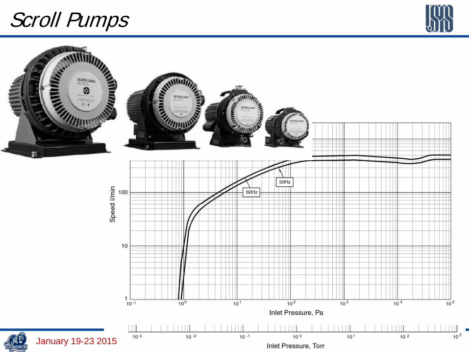
Scroll Pumps
January 19-23 2015

22
Scroll Pumps Stator Scroll
Orbiting Scroll
The scroll pump is a relative simple dry compressor, with two spiral surfaces, one fixed, on orbiting. Teflon tip seals are commonly used, and easy to replace.
Pump sizes: 15-40 m3/h; ultimate pressure ~10-2 torr.
Moving scroll may create dust at exhaust. Moisture may shorten scroll lifetime
January 19-23 2015

23
Screw Pumps – Archimedes' screw The Archimedes' screw, also called the Archimedean screw or screw-pump, is a machine historically used for transferring water from a low-lying body of water into irrigation ditches.
January 19-23 2015

24
Screw Pumps – Moving/Compress Gases
January 19-23 2015

25
Screw Pumps Screw pumps are dry compressor, consisting of a pair of
counter-rotating shafts.
Screws pumps can have very high pumping speed (up to 2500 m3/h), and lower ultimate pressure (5x10⁻³ torr)
Screw pumps can handle corrosive, abrasive and condensable gases/vapors.
Relatively high cost
January 19-23 2015

26
Lobe-type (Roots) Vacuum Pumps Roots pumps have very high gas displacement speed.
Sometime are called blowers.
Roots pumps are generally considered as dry mechanical pumps, but their gear-box contain lubrication oil.
Roots pump usually need a small backing pump.
January 19-23 2015

27
Roots Vacuum Pumps – Examples
January 19-23 2015

28
Claw Pumps – Principle
January 19-23 2015

29
Claw Pumps – Typical Parameters
January 19-23 2015

30
Turbomolecular Pumps (TMPs) TMPs are axial compressors designed
for pumping gases in the molecular flow regime. So a backing pump is required.
The gas molecules are transported towards to for-vacuum via momentum transfer from the rotating blades.
Operation range: 10-2 to 10-11 torr
Pumping speed: 10 to 10,000 l/s
TPMs are throughput pumps, meaning infinite pumping capacity
Blade rotation speed ranges from 14,000 to 90,000 rpm – making them mechanically vulnerable
January 19-23 2015

31
Turbomolecular Pumps (TMPs) Cont. Axial compressor type pumps are
very flexible designs: # of stages Various blade angles Hybrid pumps
Molecular flow exists through most of a TMP; however, transient and sometimes viscous flow occurs at the pump discharge.
The key parameter of TMPs is compression ratio, which is gas mass dependent.
Typical Compression ratios: N2 – 108 ~ 1010 He - 104 ~ 107 H2 – 103 ~ 106 January 19-23 2015

32
TMP Pumping Mechanism (1)
January 19-23 2015
Rotating pump blades accelerate gas molecules in a preferred direction.
To achieve effective compression, the blade tip speed needs to be comparable to the mean velocity of the gas molecules

33
TMP Pumping Mechanism (2)
Another way of looking at it, is to consider the rotors as moving “chevron baffles”. Their relative movement gives the baffles a higher conductance in one direction over the other.
Steep rotor blade angles produce higher conductances, which produces higher pumping speeds.
Shallow rotor blade angles produce higher compression ratios.
January 19-23 2015
34
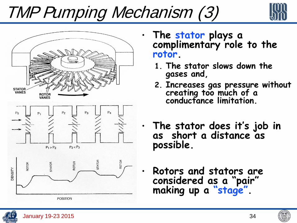
TMP Pumping Mechanism (3) • The stator plays a
complimentary role to the rotor. 1. The stator slows down the
gases and, 2. Increases gas pressure without
creating too much of a conductance limitation.
• The stator does it’s job in
as short a distance as possible.
• Rotors and stators are considered as a “pair” making up a “stage”.
January 19-23 2015

35
TMP Compression Ratio and Speed
2121
12
1
2
1
2
aW
aa
FF
PPK −==≡
At uniform temperature, Fi=Pi, the compression ratio K
2121211 aFaFWF −=2121
12
1
2
aW
aa
FF
−=
Gas flow through TMP blades:
where, F1/2: molecular flux at inlet/outlet a12: gas transmission probabilities from inlet-to-outlet a21: gas transmission probabilities from outlet-to-inlet
W: Ho coefficient, the ratio of net flux to incident flux
January 19-23 2015

36
TMP Maximum Compression Ratio – I
Using Monte Carlo method, Kruger & Shapiro calculated Kmax as function of the blade angle (ø), the blade spacing-to-cord ratio (s/b), the normalized blade speed sr = vb/vp, for single-stage (vp is most-probable molecular speed).
January 19-23 2015

37
TMP Maximum Compression Ratio – II
“Flat” blades (small ø) yet higher compression ratio Compression ratio increases with blade speed exponentially up to
molecular thermal speed, and levels off when vb >> vrms.
Outer edges of the blades contribute more with higher linear speed Compression ratio is also exponentially dependent on m1/2.
]exp[]exp[2max
p
b
mkT
b
vvvK =∝ (sr ≤ 1.5)
Gas Molecules
Kmax
Single Stage Two-Stage 15-Stage H2 1.6 ~100 1000
Ar 4 ~106 ~109
Example: s/b=1, vb(tip)=400 m/s, ø=30º
January 19-23 2015

38
TMP Maximum Compression Ratio – III
Experimentally measured compression ratios for a Pfeiffer TPU-400 pump
In a blanked-off condition, gas is admitted to the foreline
The measured compression ratio is the ratio of foreline pressure to inlet pressure
January 19-23 2015

39
TMP Maximum Pumping Speed – I
Chang & Jou [JVST A19 (2001), p2900]:
21
2112max 1 a
aaW−−
=
Kruger & Shapiro: (When K=1) 2112max aaW −=
January 19-23 2015

40
TMP Maximum Pumping Speed – II
mkT
bvW2
∝At sr ≤ 1 (or vb ≤ vp) :
Since pumping speed S = F1 x W and molecular arrival rate F ∝ (kT/m)1/2 S ∝ vb
Thus TMP pumping speed is independent of type of gases and inlet pressure (in molecular-flow region)
Measured Pumping Speed of Pfeiffer TPU-400 TMP
January 19-23 2015

41
TMP Pumping Characteristics Constant compression ratio (k) and pumping speed (S) for inlet
pressure up to 10-5 torr.
TMPs favor heavier gases. k has much stronger dependence on molecular mass, as compared to S.
January 19-23 2015

42
Hybrid TMPs with Molecular Drag Stage Turbine Blades
Drag Spiral Disks
Most modern TMPs are combined with a molecular drag stage to in crease compression ratio.
For the hybrid TMPs, backing pressure can be as high as ~ 1 torr.
January 19-23 2015

Yulin Li, January 14-18 2013 43
TMPs – Drives and Bearings

Yulin Li, January 14-18 2013 44
TMPs – Types of Bearings Typical turbine rotation speed range from 36,000 rpm for large
TMPs, to 72,000 rpm for small TMPs. Such high speeds naturally raise questions as to a reliable bearing designs.
There are three types of bearings from most TPM vendors Oil lubricated / steel ball bearings
+ Good compatibility with particles by circulating oil lubricant -- Can only install vertically + Low maintenance
Grease lubricated / hybrid bearings + Installation in any orientation + Suited for mobile systems + Lubricated for life (of the bearings) + Need cooling (forced air or water)
Free of lubricants / Magnetic suspension + Installation in any orientation + Absolutely free of hydrocarbons + Low noise and vibration levels + No wear and no maintenance

45
Hybrid TMP
Scroll Pump
RGA
Convectron Pirani Gauge
Cold Cathode
Gauge
A Typical Mechanical Pump Cart for CESR
January 19-23 2015

46
TMPs for Continuous Operations Though capture pumps are preferred pumps for most
accelerator vacuum systems, TMPs are suitable for long-term continuous operations for accelerator vacuum systems.
Typical applications are for system with very high gas loads (such as ion beam sources), or specific gases (such as helium, hydrogen, etc. such as insolation vacuum of cryo-modules).
Accelerator protection system is usually implemented to handle power failures, and for routine TMP maintenances. This include pneumatically actuated gate that can isolate the TMP from the accelerator vacuum system. Solenoid fore-line insolation valve should also included in the inter-lock. January 19-23 2015
47
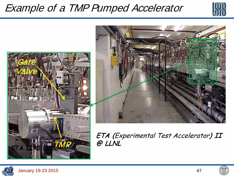
Example of a TMP Pumped Accelerator
ETA (Experimental Test Accelerator) II @ LLNL TMP
Gate Valve
January 19-23 2015

48
Sometimes bad things happen to a TMP
January 19-23 2015

49
Diffusion Pumps A diffusion pump is a vapor jet pump,
which transports gas by momentum transfer on collision with the vapor stream.
Commonly used pump fluids are hydrocarbons and fluorocarbon.
Vapor back-stream can be a source of contamination.
However, with proper cold traps, the vapor back-stream can be minimized significantly, so it can be used for HV and UHV systems.
Diffusion pumps are extremely reliable, and require minimum maintenance. For example, for CESR’s booster (the Synchrotron), we needed oil change every 30 years!
January 19-23 2015

50
Diffusion Pump Characteristics
He
N2
N2
He
Unlike TMPs, diffusion pumps favoring light gases
January 19-23 2015