
Vacuum Pump Dry Scroll IDP-3 DRAFT 12/4/17 Dry Scr… · and observe the accident prevention...
32
DRAFT 12/4/17 INSTRUCTION MANUAL Vacuum Products Division IDP-3 Dry Scroll Vacuum Pump Manual No. 699904350 Revision G October 2017
Transcript of Vacuum Pump Dry Scroll IDP-3 DRAFT 12/4/17 Dry Scr… · and observe the accident prevention...

RA
FT
12
/4/1
7
INSTRUCTION MANUAL
Vacuum Products Division
IDP-3Dry Scroll
Vacuum Pump
D
Manual No. 699904350Revision GOctober 2017

DR
AF
T 1
2/4
/17
IDP-3Dry Scroll Vacuum Pump
Copyright 2017Agilent, Inc.

IDP-3 Dry Scroll Vacuum Pump
DR
AF
T 1
2/4
/17
Warranty
Products manufactured by Seller are warranted againstdefects in materials and workmanship for twelve (12)months from date of shipment thereof to Customer, andSeller's liability under valid warranty claims is limited, atthe option of Seller, to repair, to replace, or refund of anequitable portion of the purchase price of the Product.Items expendable in normal use are not covered by thiswarranty. All warranty replacement or repair of parts shallbe limited to equipment malfunctions which, in the soleopinion of Seller, are due or traceable to defects in origi-nal materials or workmanship. All obligations of Sellerunder this warranty shall cease in the event of abuse,accident, alteration, misuse, or neglect of the equipment.In-warranty repaired or replaced parts are warranted onlyfor the remaining unexpired portion of the original war-ranty period applicable to the repaired or replaced parts.After expiration of the applicable warranty period, Cus-tomer shall be charged at the then current prices for parts,labor, and transportation.
Reasonable care must be used to avoid hazards. Sellerexpressly disclaims responsibility for loss or damagecaused by use of its Products other than in accordancewith proper operating procedures.
Except as stated herein, Seller makes no warranty,expressed or implied (either in fact or by operation oflaw), statutory or otherwise; and, except as stated herein,Seller shall have no liability under any warranty,expressed or implied (either in fact or by operation oflaw), statutory or otherwise. Statements made by any per-son, including representatives of Seller, which are incon-sistent or in conflict with the terms of this warranty shallnot be binding upon Seller unless reduced to writing andapproved by an officer of Seller.
Warranty Replacement and AdjustmentAll claims under warranty must be made promptly afteroccurrence of circumstances giving rise thereto, and mustbe received within the applicable warranty period bySeller or its authorized representative. Such claims shouldinclude the Product serial number, the date of shipment,and a full description of the circumstances giving rise tothe claim. Before any Products are returned for repairand/or adjustment, written authorization from Seller or itsauthorized representative for the return and instructionsas to how and where these Products should be returnedmust be obtained. Any Product returned to Seller forexamination shall be prepaid via the means of transporta-tion indicated as acceptable by Seller. Seller reserves theright to reject any warranty claim not promptly reportedand any warranty claim on any item that has been alteredor has been returned by non-acceptable means of trans-portation. When any Product is returned for examinationand inspection, or for any other reason, Customer shall beresponsible for all damage resulting from improper pack-ing or handling, and for loss in transit, notwithstandingany defect or non-conformity in the Product. In all cases,Seller has the sole responsibility for determining the causeand nature of failure, and Seller's determination withregard thereto shall be final.
If it is found that Seller's Product has been returned with-out cause and is still serviceable, Customer will be noti-fied and the Product returned at the Customer's expense;in addition, a charge for testing and examination may bemade on Products so returned.
iii

IDP-3 Dry Scroll Vacuum Pump
This page intentionally left blank.
DR
AF
T 1
2/4
/17

IDP-3 Dry Scroll Vacuum Pump
DR
AF
T 1
2/4
/17
Contents
Warranty . . . . . . . . . . . . . . . . . . . . . . . . . . . . . . . . . . iiiWarranty Replacement and Adjustment. . . . . . . . iii
Instructions for Use . . . . . . . . . . . . . . . . . . . . . . . . . . . 1General Information . . . . . . . . . . . . . . . . . . . . . . . 1
Storage . . . . . . . . . . . . . . . . . . . . . . . . . . . . . . 1Installation . . . . . . . . . . . . . . . . . . . . . . . . . . . . . . 2Use . . . . . . . . . . . . . . . . . . . . . . . . . . . . . . . . . . . . 2Maintenance . . . . . . . . . . . . . . . . . . . . . . . . . . . . . 2
Technical Information . . . . . . . . . . . . . . . . . . . . . . . . . 3Unpacking and Inspection . . . . . . . . . . . . . . . . . . 6Installation . . . . . . . . . . . . . . . . . . . . . . . . . . . . . . 7
Safety . . . . . . . . . . . . . . . . . . . . . . . . . . . . . . . 7Startup . . . . . . . . . . . . . . . . . . . . . . . . . . . . . . 7Electrical Connections . . . . . . . . . . . . . . . . . . 7Run Currents . . . . . . . . . . . . . . . . . . . . . . . . 11Start Current . . . . . . . . . . . . . . . . . . . . . . . . . 11Mechanical Connections . . . . . . . . . . . . . . . 12
Operation . . . . . . . . . . . . . . . . . . . . . . . . . . . . . . 12Cleaning the Pump . . . . . . . . . . . . . . . . . . . . 12Startup Procedure . . . . . . . . . . . . . . . . . . . . . 12Shutdown Procedure . . . . . . . . . . . . . . . . . . 12
IDP-3 Inlet Valve Kit . . . . . . . . . . . . . . . . . . . . . . 13Model Selection . . . . . . . . . . . . . . . . . . . . . . 13Installation . . . . . . . . . . . . . . . . . . . . . . . . . . 14
Troubleshooting . . . . . . . . . . . . . . . . . . . . . . . . . 16Maintenance . . . . . . . . . . . . . . . . . . . . . . . . . . . . 17
Kits and Service Options . . . . . . . . . . . . . . . 17Cleaning . . . . . . . . . . . . . . . . . . . . . . . . . . . . 17Tip Seal Replacement . . . . . . . . . . . . . . . . . . 17Pump Module Replacement . . . . . . . . . . . . . 19
Request for Return Health and Safety Certification
List of FiguresFigure Caption Page
1 Interface Drawing with Dimensions (AC Version) . . . . . . . . . . . . . . . . . . . . . . . . . . . . . . . . . . . 4
2 Interface Drawing with Dimensions (DC Version) . . . . . . . . . . . . . . . . . . . . . . . . . . . . . . . . . . . 5
3 Outline Drawing and Principal Items . . . . . . 64 24 VDC Power Cable . . . . . . . . . . . . . . . . . . 85 Shield Cable . . . . . . . . . . . . . . . . . . . . . . . . . 86 RPM. vs. 0-10 V Speed Control Signal. . . . . . 97 Grounding Plug and Outlet . . . . . . . . . . . . . 108 ON/OFF Power Switch . . . . . . . . . . . . . . . . 129 IDP-3 with Inlet Valve. . . . . . . . . . . . . . . . . 1310 Mount Inlet Valve with IDP-3 Pump . . . . . . 1411 24 VDC Rev Inlet Valve Kit . . . . . . . . . . . . 1512 Tip Seal Seating. . . . . . . . . . . . . . . . . . . . . . 1813 Exploded View of Pump Body . . . . . . . . . . 1914 Module Replacement - Exploded View . . . 20
Table Title Page
1 Specifications . . . . . . . . . . . . . . . . . . . . . . . . 32 IDP-3 Power Cord Selection . . . . . . . . . . . . . 73 IDP-3 Typical Run Currents (A) . . . . . . . . . . 114 Typical IDP-3 Maximum Starting Current and
Duration . . . . . . . . . . . . . . . . . . . . . . . . . . 115 Inlet Valve Kit Selection . . . . . . . . . . . . . . . 136 IDP-3 Model Numbers with Inlet Valve. . . . 137 Technical Specifications . . . . . . . . . . . . . . . 148 Troubleshooting Chart. . . . . . . . . . . . . . . . . 169 Tip Seal Replacement Kit . . . . . . . . . . . . . . 17
v

IDP-3 Dry Scroll Vacuum PumpD
RA
FT
12
/4/1
7
This page intentionally left blank.

IDP-3 Dry Scroll Vacuum Pump
DR
AF
T 1
2/4
/17
Instructions for Use
General InformationThis equipment is designed for use by professionals. Theuser should read this instruction manual and any otheradditional information supplied by Agilent before operat-ing the equipment. Agilent will not be held responsiblefor any events that occur due to non-compliance withthese instructions, improper use by untrained persons,non-authorized interference with the equipment, or anyaction contrary to that provided for by specific nationalstandards.
The IDP-3 is a hermetic, dry scroll vacuum pump. Thispump is suitable for pumping air or inert gases. The pumpis not intended to pump corrosive, explosive, or particu-late-forming gases.
The following paragraphs contain all the information nec-essary to guarantee the safety of the operator when usingthe equipment. Detailed information is supplied in“Technical Information” on page 3.
This manual uses the following standard safety protocol:
StorageWhen transporting and storing the pump, the followingenvironmental requirements should not be exceeded:
Preparation for Installation
The pump is supplied in a special protective packing. Ifthis shows signs of damage, which may have occurredduring transport, contact your local sales office.
Total weight of the packing, IDP-3 pump included, isapproximately 10.5 kg (23 lbs).
WARNING The warning messages are for attracting the attention of the operator to a partic-ular procedure or practice which, if not followed correctly, could lead to serious injury.
CAUTION The caution messages are displayed before procedures, which if not fol-lowed, could cause damage to the equipment.
NOTE The notes contain important informa-tion taken from the text.
Temperature: 20 °C to +60 °C (4 °F to 140 °F)
Relative humidity: 0 to 95% (non-condensing)
WARNING When unpacking the pump, be sure not to drop it and avoid any kind of sudden impact or shock vibration to it.
NOTE Normal exposure to the environment cannot damage the pump. Neverthe-less, it is advisable to keep the pump inlet closed until the pump is installed in the system.
1

IDP-3 Dry Scroll Vacuum Pump D
RA
FT
12
/4/1
7
InstallationDo not install or use the pump in an environmentexposed to atmospheric agents (rain, snow, ice), dust,aggressive gases, or in explosive environments or thosewith a high fire risk.
If placing the IDP-3 pump inside an enclosure, provideample room to supply ambient air to both the front andrear air intakes of the pump.
During operation, the following environmentalconditions must be respected:
There are four versions of the IDP-3:
❑ 100 VAC, 50/60 Hz❑ 115 VAC, 60 Hz❑ 220-230 VAC, 50/60 Hz❑ 24 VDC
For the:
❑ AC version, connect the pump to the power supply using an IEC-320 style power cord of at least 10 A capacity.
❑ DC version, connect to the power supply using the power cord supplied with the pump.
UseIn order to reach maximum vacuum, the pump must beleft running for about an hour with the inlet sealed.
There are no special instructions for starting the pump; itneed only be switched on using the On/Off switch.
There are no special instructions for stopping the pump; itneed only be disconnected from the electric powersource by the On/Off switch.
MaintenancePersonnel responsible for pump operation and mainte-nance must be well-trained and aware of the accidentprevention rules.
If a pump is to be discarded, it must be disposed of inaccordance with specific national standards.
Temperature: +5 °C to +40 °C (41 °F to 104 °F)
Relative humidity: 0 to 95% (non-condensing)
CAUTION Be certain that your electrical mains power voltage corresponds to that indi-cated on the rear of the pump.
CAUTION Never disturb the two hex head bolts on either side of the pump. Disturbing these bolts will cause loss of perfor-mance and/or pump damage.
WARNING The pump is designed for operation with neutral or noncorrosive fluids. It is absolutely forbidden to use it with potentially explosive or inflammable substances.
WARNING ❑ Death may result from contact with high voltages. Always take extreme care and observe the accident prevention regulations in force.
❑ When machine is powered up, be careful of moving parts and high voltages.
❑ If you have to perform maintenance on the pump after a considerable time in operation, allow it to cool as the tem-perature of the outer surface may be in excess of 60 °C.
❑ Always disconnect your power supply to the pump before beginning maintenance work.
NOTE Before returning the pump to the factory for repair, the “Health and Safety” sheet attached to this instruction manual must be completed and sent to the local sales office. A copy of the sheet must be inserted in the pump package before shipping.
2

IDP-3 Dry Scroll Vacuum Pump
DR
AF
T 1
2/4
/17
Technical Information
Table 1 Specifications
Model IDP-3 Dry Scroll Single Hermetic Vacuum Pump
Interface dimensions See Figure 1 on page 4
Peak pumping speed ❑ 50 Hz: 50 L/m, 3.0 m3/hr (1.8 cfm)❑ 60 Hz: 60 L/m, 3.6 m3/hr (2.1 cfm)❑ 24 VDC: 60 L/m, 3.6 m3/ hr (2.1 cfm) at full speed setting
Media No corrosive, explosive or particulate forming gases
Ultimate pressure 2.5 x 101 Torr (3.3 x 101 mbar)
Maximum inlet pressure 1.0 atmosphere (0 psig)
Maximum outlet pressure 6.5 psig
Inlet connection NW16
Exhaust connection Female 1/4" National Pipe Thread (10 mm hose barb provided)
Gas ballast Female 1/8" National Pipe Thread (adapter provided)
Ambient operating temperature 5 °C to 40 °C (41 °F to 104 °F)
Storage temperature –20 °C to 60 °C (–4 °F to 140 °F)
Motor rating ❑ AC: 0.16 HP (0.12 kW)❑ DC: 0.16 HP (0.12 KW) Peak rating: 0.27 HP (0.20 KW)
Operating voltages ❑ 1 phase/ 100 VAC, ±10%, 50/60 Hz, 2.31/2.39 FLA❑ 1 phase/ 115 VAC, ±10%, 60 Hz, 2.41 FLA❑ 1 phase/ 220-230 VAC, ±10%, 50/60 Hz, 1.17/1.26 FLA❑ 24 VDC, ±10%, 7.5 FLA
Run current See Table 3 on page 11
Motor thermal protection Automatic thermal protection
Operating speed ❑ 60 Hz: 3200 RPM, 50 Hz: 2600 RPM❑ 24V DC: variable speed, factory setting@ 3200 RPM
Cooling system Air-cooled
Weight Pump only: 9.5 kg (21 lbs)Shipping weight: 10.5 kg (23 lbs)
Leak rate (with exhaust and gas ballast sealed)
<1 x 10⁶ sccs helium
Vibration level at inlet, per ISO 10816-1 1.5 mm/sec
Noise level, per ISO 11201 55 dBA
Installation ❑ Pollution Degree: 2❑ Installation Category: II❑ Altitude 2000 m, indoor usage and storage
3

IDP-3 Dry Scroll Vacuum Pump D
RA
FT
12
/4/1
7
Figure 1 Interface Drawing with Dimensions (AC Version)
4

IDP-3 Dry Scroll Vacuum Pump
DR
AF
T 1
2/4
/17
Figure 2 Interface Drawing with Dimensions (DC Version)
5

IDP-3 Dry Scroll Vacuum Pump D
RA
FT
12
/4/1
7
a
Figure 3 Outline Drawing and Principal Items
1. Front Cowling Screws; M5 (4)
2. Front Cowling
3. Inlet (NW16)
4. Inlet Screen
5. 10 mm Hose Barb
6. Gas Ballast Port (1/8" NPT adapter provided)
7. Frame
8. Base
9. Mounting Holes; (4) for 1/4" or M6 Hardware
10. Rear Cowling
11. Rear Cowling Screws: M5 (4)
12. On/Off Switch/Power Connection (IEC-320) or power cord with free leads for DC version
13. Hour Meter
Unpacking and Inspection1. Orient the shipping container with This End Up
on top.
2. Open the box and carefully lift the IDP-3 and foam blocks out of the box. Remove the foam blocks.
3. Save the carton and all packing materials.
4. Inspect the pump for damage. If there is shipping damage, contact the freight carrier and your local Agilent sales office immediately.
1
2
3
4
5
6
7
8
10
12
13
11
9
12
6

IDP-3 Dry Scroll Vacuum Pump
DR
AF
T 1
2/4
/17
Installation
SafetyDo not remove or modify any safety or insulating equip-ment from the pump. To do so may create a serious safetyhazard and may void the warranty.
There are four versions of the IDP-3:
❑ 100 VAC, 50/60 Hz❑ 115 VAC, 60 Hz❑ 220-230 VAC, 50/60 Hz❑ 24 VDC
CAUTION Ensure that the pump version conforms to the supply voltage before using.
Startup1. Check that the inlet screen is installed before
beginning operation.
2. Operate the pump at an ambient temperature of 5 °C to 40 °C (41 °F to 104 °F), otherwise damage to the pump or shortened operating life may result.
Electrical Connections
Power Cord
Several power cord options are available from your Agilent dealer. Descriptions of the available power cordsand their ordering numbers are given in Table 2.
WARNING ❑ This pump is capable of pumping and exhausting air and inert gases only. It is not designed to pump explosive, flammable, corrosive or particulate forming gases. They can cause bodily injury, explosion, or fire.
❑ Install in an area that is not exposed to rain, steam, or excessive humidity. They can cause electric shock, short circuits, and severe bodily injury.
❑ Before inspecting or servicing the pump, be sure the electrical supply is discon-nected.
❑ The gas ballast must be sealed whenever pumping any gas not intended to be vented to the atmosphere.
❑ An exhaust silencer option is available for those applications in which it is desirable to diminish the sound level produced by the pump.❑ To prevent bodily injury, avoid exposing any part of the human body to vacuum.
CAUTION Although the pump can pump trace particulates normally found in the atmosphere, it is not designed to process solids, chemicals, powders, solvents, condensates, or other particu-lates. They can damage the equipment, degrade its performance, or shorten its useful life.
WARNING Do not insert a finger or any foreign object in the path of the fan; serious personal injury may result or the pump may be damaged.
CAUTION Do not block the fan ducts. Blocking these ducts can cause pump overheat-ing. A pump surface temperature in excess of 65 °C (150 °F) is potentially damaging. If such conditions are observed, turn the pump off and allow it to cool. Disassemble, inspect for dam-age, and repair, if necessary.
NOTE For high voltage operation, the pump must be connected to the power supply using a high voltage IEC-320 type power cord of at least 10 A capacity.
CAUTION Be certain that your electrical mains power voltage corresponds to that indi-cated on the rear of the pump.
Table 2 IDP-3 Power Cord Selection
Country Power Cord Specification Order
Europe 10 A / 220-230 VAC, 2.5 m 656494220
Denmark 10 A / 220-230 VAC, 2.5 m 656494225
Switzerland 10 A / 230 VAC, 2.5 m 656494235
UK/Ireland 13 A / 230 VAC, 2.5 m 656494250
7
IDP-3 Dry Scroll Vacuum Pump D
RA
FT
12
/4/1
7
Power Cord (24 VDC)
The interface for the 24VDC power entry is a 9-pin D-subconnector (Figure 4). On this connector pins 4, 5 and 9are all connected 24V+. Pins 2, 7 and 8 are all connectedto 24V-. It is recommended that the Power Cord (AgilentPart Number X3803-60033) included with the pump isused when connecting to the power supply. To correctlyconnect the power cord to a power supply, attach the16Awg red wire to 24V+ and attach the Black wire to24V-.
Figure 4 PIN Information
The IDP3 24 VDC model also offers variable speed con-trol. Apply 0-10 VDC through Pin1 and Pin 6 of the 9-pinD-sub connector, or white (+) and blue (-) 20AWG wireson the Agilent power cord supplied. The motor runs atfull speed if there is no control signal supplied.
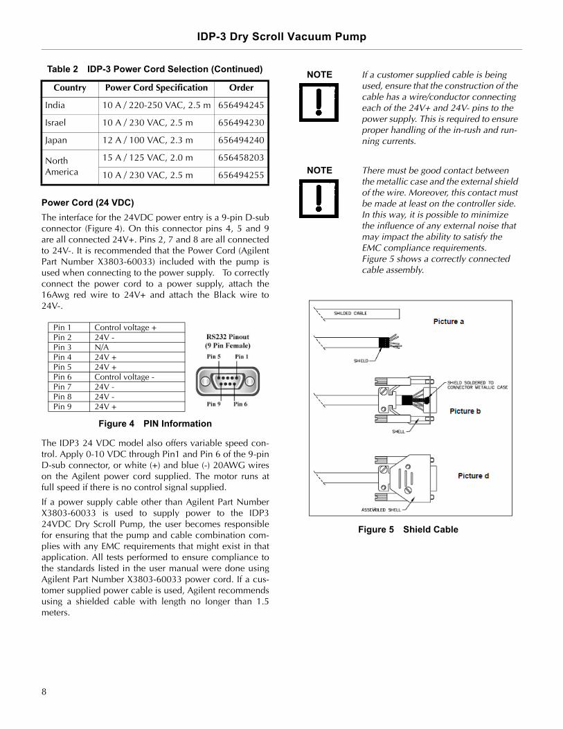
If a power supply cable other than Agilent Part NumberX3803-60033 is used to supply power to the IDP324VDC Dry Scroll Pump, the user becomes responsiblefor ensuring that the pump and cable combination com-plies with any EMC requirements that might exist in thatapplication. All tests performed to ensure compliance tothe standards listed in the user manual were done usingAgilent Part Number X3803-60033 power cord. If a cus-tomer supplied power cable is used, Agilent recommendsusing a shielded cable with length no longer than 1.5meters.
Figure 5 Shield Cable
India 10 A / 220-250 VAC, 2.5 m 656494245
Israel 10 A / 230 VAC, 2.5 m 656494230
Japan 12 A / 100 VAC, 2.3 m 656494240
North America
15 A / 125 VAC, 2.0 m 656458203
10 A / 230 VAC, 2.5 m 656494255
Table 2 IDP-3 Power Cord Selection (Continued)
Country Power Cord Specification Order
Pin 1 Control voltage +Pin 2 24V -Pin 3 N/APin 4 24V +Pin 5 24V +Pin 6 Control voltage -Pin 7 24V -Pin 8 24V -Pin 9 24V +
NOTE If a customer supplied cable is being used, ensure that the construction of the cable has a wire/conductor connecting each of the 24V+ and 24V- pins to the power supply. This is required to ensure proper handling of the in-rush and run-ning currents.
NOTE There must be good contact between the metallic case and the external shield of the wire. Moreover, this contact must be made at least on the controller side. In this way, it is possible to minimize the influence of any external noise that may impact the ability to satisfy the EMC compliance requirements. Figure 5 shows a correctly connected cable assembly.
8

IDP-3 Dry Scroll Vacuum Pump
DR
AF
T 1
2/4
/17
The minimum rotation speed of the motor is 2200 rpm±10%* when the control is between 0-2.6 V. The motorreaches the full speed when the signal is 8.2 to 10 V.Speed increases proportionally between 2.6 and 8.2 V(Figure 6).
Figure 6 RPM. vs. 0-10 V Speed Control Signal
*RPM varies with power supply's voltage. Generally, the higherthe power voltage is, the higher rotating speed. Base pressure decreases and power consumption increases asthe RPM increases.
Grounding Instructions
This product should be grounded. In the event of an elec-trical short circuit, grounding reduces the risk of electricshock by providing an escape wire for the electric cur-rent. This pump is equipped with a power cord that has agrounding wire with an appropriate grounding plug. Theplug must be inserted into an outlet that is properlyinstalled and grounded in accordance with all local codesand ordinances.
DANGER Improper installation of the grounding plug can result in a risk of electrical shock.
For United States and Canadian instal-lations:
❑ When this product is configured for use on a nominal 120 V circuit, it must be used with a grounding plug that looks like the plug illustrated in Figure 7.
❑ If repair or replacement of the cord or plug is necessary, connect the grounding wire to the grounding terminal only.
❑ The grounding wire is insulated and its outer surface is green. It may or may not have yellow stripes.
❑ When this product is configured for use on a nominal 220 V circuit, it must be used with a factory supplied cord and plug that permits connection to the proper electric circuit. See “Electrical Connections” on page 7 for proper rating and type of cord set.
WARNING Check with a qualified electrician or serviceman if the grounding instructions are not completely understood, or if you are in doubt as to whether the product is properly grounded.
Do not modify the plug provided; if it does not fit the outlet, have the proper outlet installed by a qualified electrician.
Connect the product only to an outlet that has the same configuration as the plug.
Do not use an adapter with this product.
9

IDP-3 Dry Scroll Vacuum Pump D
RA
FT
12
/4/1
7
Figure 7 Grounding Plug and Outlet
Grounding Instructions (DC version)
Extension Cords
If you must use an extension cord with this product:
❑ For this product, Agilent recommends using only extension cords with a minimum of 16-gauge wire and a maximum length of 25 feet (7.6 m).
❑ Use only a 3-wire extension cord that will accept the plug.
❑ Make sure your extension cord is in good condition.❑ Be sure the extension cord is rated high enough to
carry the current your product will draw. An under-sized cord will cause a drop in line voltage resulting in loss of power and overheating.
WARNING If the product must be reconnected for use on a different type of electric cir-cuit, the connector should be replaced by qualified service personnel.
Grounding
Grounded Outlet
Pin
GroundedOutlet
Box NOTE Ensure the 24 VDC power supply and 0-10 V power supply are grounded according to the correct practice.
10

IDP-3 Dry Scroll Vacuum Pump
DR
AF
T 1
2/4
/17
Run CurrentsTypical run currents listed in Table 3 are approximately constant from minimum to maximum intake pressure.
Start CurrentTable 4 lists the typical IDP-3 maximum starting current and duration.
Table 3 IDP-3 Typical Run Currents (A)
Frequency 100 V Nominal 115 V Nominal 220 - 230 V Nominal
90 V 100 V 110 V 103.5 V 115 V 126.5 V 198 V 220 V 230 V 253 V
60 Hz 2.3 2.2 2.2 2.1 2.0 2.0 1.1 1.1 1.1 1.1
50 Hz 1.7 1.7 1.9 N/A N/A N/A 0.8 0.8 0.8 1.0
DC Version
24 V Nominal
21.6 V 24 V 26.4 V
6.8 7.0 8.2
Table 4 Typical IDP-3 Maximum Starting Current and Duration
Mains Voltage50 Hz 60 Hz DC
Current (A) Time (ms) Current (A) Time (ms) Current (A) Time (ms)
100 V 2.8 300 2.8 500 N/A N/A
115 V N/A N/A 3.3 500 N/A N/A
220 V 1.3 300 1.3 500 N/A N/A
230 V 1.4 300 1.4 300 N/A N/A
24 V N/A N/A N/A N/A 15 300 ms
11

IDP-3 Dry Scroll Vacuum Pump D
RA
FT
12
/4/1
7
Mechanical Connections
Pump Inlet
Use NW16, or larger, clean vacuum hardware with asshort a length as practical between the pump and vacuumchamber.
Insert a bellows between the pump and vacuum chamberto provide both vibration isolation and strain relief.
Pump Exhaust
A female 1/4" National Pipe Thread exhaust fitting islocated on the front of the pump. Additionally, a 10 mm(3/8") hose barb fitting is provided. To avoid overheatingthe pump, do not restrict the exhaust flow with longlengths of small diameter tubing. Use as short as practicallengths of 10 mm ID, or larger, diameter hardware.
Gas Ballast
The pump incorporates an automatic gas ballast to pre-vent water and other condensates from accumulatingwithin the pump. The standard configuration has a sealscrew installed in the 1/4-20 thread in the top of theexhaust manifold (item 6 on Figure 3 on page 6). Thisconfiguration can be used for relatively dry applications.When appreciable amounts of water, solvents, etc., arebeing pumped, remove the seal screw and replace it withthe provided adapter and 1/8" NPT sintered filter plug. Donot exceed 25 in-lb of torque when installing the adapterinto the manifold.
For applications where the ingress of atmospheric air isundesirable, dry nitrogen at a flow rate of approximately5 l/min can be provided to the gas ballast. Remove the1/8" NPT sintered filter plug from the adapter and replaceit with an appropriate fitting (supplied by end user).
Operation
Cleaning the PumpUnlike conventional oil-sealed pumps, Agilent dry scrollpumps do not contain fluid for the cleansing of accumu-lated dust and debris. Run the pump periodically at atmo-sphere for a minute or two to flush it out. Untilexperience is gained on your specific process, flush thepump regularly and adjust this schedule according toyour specific conditions.
Startup Procedure1. Make sure that the pump is configured for the mains
voltage to which the pump is connected.
Figure 8 ON/OFF Power Switch
2. Switch the pump ON using the pump ON/OFF switch for AC versions. The 24 VDC pump switches on once the 24 VDC power is connected to the pump and is switched on.
Shutdown ProcedureTo shutdown the pump:
❑ Switch the pump OFF for AC versions. For a DC ver-sion, switch off the 24 VDC power or disconnect the power cord.
WARNING The gas ballast must be sealed when-ever pumping any gas not intended to be vented to atmosphere.
NOTE The pump ON/OFF switch is a rocker type switch that has symbols in accor-dance with IEC Publication 417 to represent the ON and OFF positions. Figure 8 shows a switch in the ON position.
ON
OFF
12

IDP-3 Dry Scroll Vacuum Pump
DR
AF
T 1
2/4
/17
IDP-3 Inlet Valve KitThe IDP-3 scroll pump is provided with an exhaust valveto prevent rapid leak-up to atmosphere when turned off.However, any vacuum pump generates a small increasein inlet line pressure when turned off. A small amount ofpump debris can be carried back into a vacuum line orchamber when the pump is turned off. For applicationswhere the process is sensitive to pump debris, to preventthis, install a fast acting, automatic, normally closedvalve. For your convenience, Agilent offers an optionalinlet valve and operator kit for the IDP-3 (Figure 9).
Figure 9 IDP-3 with Inlet Valve
This kit includes upper and lower brackets, delay onmade timer, solenoid valve with wire harness to the pumpand a cooling fan, centering O-ring, quick clamp, nutsand screws for installation, a cord clamp, and a ¼" flexi-ble screw driver.
❑ The opening of this valve occurs a minimum of 10 s after pump startup.
❑ Valve closing occurs25 ms after pump shut off.
Model SelectionThe inlet valve kit can be obtained separately for existingstandard IDP-3 pumps. Refer to Table 5 for model selec-tion, and “Installation” on page 14 for detailed proce-dures.
It is strongly recommended to order the IDP-3 pump withthe inlet valve factory-installed to prevent malfunctionsdue to incorrect installation (see Table 6).
Table 5 Inlet Valve Kit Selection
Part Number Model Input AC
VPI16IDP220 IDP3A01 220-230 V 50/60 Hz
VPI16IDP115 IDP3B01 115 V 60 Hz
VPI16IDP100 IDP3C01 100 V 50/60 Hz
VPI16IDP24DC IDP3D01 24 VDC
Table 6 IDP-3 Model Numbers with Inlet Valve
Part Number Input AC
IDP3A21 220-230V 50/60Hz
IDP3B21 115V 60Hz
IDP3C21 100V 50/60Hz
IDP3D21 24 VDC
13

IDP-3 Dry Scroll Vacuum Pump D
RA
FT
12
/4/1
7
The technical specification is shown in Table 7.
Installation
AC
Mount the valve body on the pump inlet with centering ring and quick clamp provided in the pump package of IDP3A21B21 or C21. Observe valve body orientation, otherwise the valve will not function properly (Figure 10).
Figure 10 Mount Inlet Valve with IDP-3 Pump
NOTE If VPI16IDP100, VPI16IDP115, or VPI16IDP220 is purchased separately from the IDP3 AC rev pump, fol-low the installation procedure in the IDP3 inlet valve kit instruction manual (PN# 699904370).
Table 7 Technical Specifications
Leak Rate:
❑ Body < 1X10⁻⁹ atm cc/sec He
❑ Seal <1X10⁻⁹ atm cc/sec He
Closing time (after solenoid valve power loss)
25 ms
Closing burst 0.01 torr-liter
Power 7.7 W (AC), 9.5 W (DC)
Materials:
❑ Body Aluminum (6061-T6)
❑ Seal Viton
Temperature Range:
❑ Valve Body 0~100 °C
❑ Solenoid 0~50 °C
14

IDP-3 Dry Scroll Vacuum Pump
DR
AF
T 1
2/4
/17
DC
24VDC inlet valve kit for IDP series (VPI16IDP24DC) isshown in Figure 11. It is included in the package if apump with part number IDP3D21 is purchased. To install:
1. Plug the connector at the end of solenoid valve to the DC jacket on the rear cowling.
2. Follow the same instructions to mount the valve body to the pump inlet as AC rev.
Figure 11 24 VDC Rev Inlet Valve Kit
15

IDP-3 Dry Scroll Vacuum Pump D
RA
FT
12
/4/1
7
TroubleshootingUse the Troubleshooting chart in Table 8 to assist in defining a problem, determining a possible cause, and defining actionsteps to remedy the situation.
Table 8 Troubleshooting Chart
Problem Possible Causes Corrective Actions
Will not start Motor thermal protector open Allow motor to cool.Identify cause of overload.
Excessive voltage drop Check size and length of cable.
Defective motor Inspect. Contact Agilent .
Poor ultimate pressure
System leak Locate and repair leak.
Water in pump Flush pump with air or dry nitrogen.
Solvent in pump Flush pump with air or dry nitrogen.Install trap or filter.
Seals worn out Replace tip seals.
Poor conductance to pump Replumb with shorter and/or larger diameter tubing.
Hammering noise Pump overheated Check ventilation to pump.Check ambient temperature.
Debris in pump Check intake screen.Flush pump.Disassemble pump and inspect.
Pump runs intermittently
Motor thermal protector is cycling open and closed.*
Allow the motor to cool.Identify the cause of the overload.
* The IDP-3 is equipped with an auto-reset thermal motor protector. This protector automatically shuts down the pump when it detects an overload condition, and automatically restarts the pump when the motor has cooled to within an acceptable temperature range.
16

IDP-3 Dry Scroll Vacuum Pump
DR
AF
T 1
2/4
/17
Maintenance
Kits and Service OptionsAgilent pumps will provide many years of trouble-freeservice if the maintenance procedures and intervals areobserved. Cleaning and tip seal replacement are recom-mended when pump base pressure has risen to an unac-ceptably high level for your application. If your pumpexhibits humming or grinding noises from the bearings, amajor overhaul should be done by Agilent personnel oran authorized rebuild center. Advance exchange pumpsare available to minimize downtime.
The parts needed for tip seal replacement on the IDP-3are available in the kit described in Table 9. This kit con-tains seals and O-rings, and can be obtained from yourAgilent dealer.
Cleaning
Exterior
The exterior surfaces of the IDP-3 may be cleaned withalcohol or mild detergents only.
Interior
Run the pump periodically at atmosphere for a minute ortwo to flush it out. For more information, see “Cleaningthe Pump” on page 12.
Tip Seal ReplacementThe parts and tools required to replace tip seals are listedbelow:
❑ Tip Seal Replacement Kit P/N IDP3TS ❑ 4 mm Allen wrench❑ Razor blade or side-cutting pliers❑ Compressed air (optional)
Figure 13 on page 19 shows the various componentsinvolved in a tip seal replacement procedure. Refer toFigure 13 as you follow the procedure.
To remove the worn tip seals:
1. Disconnect the pump from electrical power.
2. Remove (4) M5 socket head bolts (item 1).
3. Remove the front cowling and disconnect the electri-cal connector and set the cowling aside.
4. Remove (4) M5 bolts (item 4).
5. Remove the outboard housing axially off the frame (item 5).
6. Remove and discard the worn tip seals (item 6) and the main O-ring (item 7).
7. If compressed air is available, blow any remaining seal debris off the scroll parts. If seal debris is attached to the sides, use a razor or Exacto knife to scrape the debris off.
To install the new seals and O-rings:
1. Unpack the tip seals.Two tip seals are provided in the kit; one fits the orbiting scroll and the other fits the outboard housing scroll.
2. Install the correct tip seal into the groove of the orbit-ing scroll (item 8) by:
a. Facing the cutting burrs on the edges of the seal upwards, inserting the tightly curled end into the center of the orbiting scroll, until the seal is well seated in the groove and the anchor inside the groove protrudes into the seal's side (Figure 12). The seal may need to be pushed firmly to sit well into the groove.The seal is correctly installed when it sits in its entirety into the groove, sticking out just slightly over the top.
Table 9 Tip Seal Replacement Kit
Part Number
Description Contents
IDP3TS Replacement Tip Seal Set
Replacement Tip Seals and O-rings for IDP-3 pumps
WARNING If dangerous gases were being pumped, flush the pump with air or inert gas for at least 10 minutes prior to disassembly.
17

IDP-3 Dry Scroll Vacuum Pump D
RA
FT
12
/4/1
7
Figure 12 Tip Seal Seating
If the seal's curl seems to have lost some of its curl radius and does not fit into the center of the scroll, re-form the sealend using a pair of round nose pliers to make it fit into the groove. Tip-Seal kit instructions indicate which face shouldbe up (valid for Service Kits only).
b. Cutting the tip seal off about 1/8" (3 mm) from the outer end of the groove.
3. Install the correct tip seal into the groove of the outboard housing scroll (item 4) as in step 3.
4. Place the new main O-ring into the groove in the frame (item 10). Ensure that the groove is clean.
5. Ensure the sealing face of the outboard housing is clean. Carefully replace the outboard housing by lining up the locating pins. Ensure the tip seal has not fallen out of its groove.
6. Reinstall (4) M5 bolts (item 4) and torque the (4) M5 bolts to 5.6 N-m (50 in-lb).
7. Reconnect the electrical connector at the front cowling.
8. Place the front cowling in place and replace the M5 bolts.
9. Reconnect the pump to the electrical power mains.
18

IDP-3 Dry Scroll Vacuum Pump
DR
AF
T 1
2/4
/17
Figure 13 Exploded View of Pump Body
To test the pump:
1. Run the pump for about 5 seconds. Verify that the front fan is running.
If you hear loud noises or observe labored operation,this indicates that the tip seal or main O-ring are pos-sibly out of place.
2. Disassemble and repair as necessary.
The pump is now ready to return to service.
Pump Module ReplacementThe parts and tools required to replace the pump moduleinclude:
❑ Replacement Module Kit P/N IDP3❑ 4 mm Allen wrench
Figure 14 on page 20 shows the various componentsinvolved in pump module replacement.
To replace the pump module:
1. Disconnect the pump from electrical power and dis-connect the power cord from the power cord socket.
2. Stand the pump on the fan cowling (cover the work surface to protect the pump finish).
3. Loosen the four M5 captive screws (item 1) that hold the motor cowling in place (item 2), but do not remove the motor cowling.
4. Stand the pump on the motor cowling (cover the work surface to protect the pump finish).
5. Remove the four M5 socket head screws (item 3) that secure the fan cowling (item 4).
1
2
3
4
7
8
9
1. Front Cowling Bolts; M5 (4) 2. Front Cowling3. Frame Bolts; M5 (4) 4. Outboard Housing5. Tip Seals (Not shown) 6. Main O-ring Parker No. 2-160
(Not shown)7. Locating Pins (2) 8. Orbiting Scroll9. Frame
NOTE Newly installed tip seals may require several hours of run time to seat prop-erly and enable the pump to meet speed and base pressure specifications.
19

IDP-3 Dry Scroll Vacuum PumpD
RA
FT
12
/4/1
7
This page intentionally left blank.
6. Remove the fan cowling, disconnect the electrical connector, and set the cowling aside.
7. Remove the four M5 socket head screws (item 5) that secure the base plate (item 6); remove the base plate, and set aside.
8. Lay the pump on its side and slide the motor cowling off the pump. Disconnect the electrical connector and set the cowling aside.
9. Remove the four M6 button head screws (item 7) that secure the motor to the pump module and set the motor aside.
10. Install the new coupling spider (item 8) to the coupling (motor side or pump module side) and install the motor to the replacement pump module with the label facing up (in the same direction as the inlet flange of the pump module). Secure the motor with four M6 button head screws.
11. Reconnect the electrical connector on the motor cowl-ing to the motor.
12. Tuck the electrical connector behind the aluminum plate mounted to the motor cowling (item 9) and slide the motor cowling into place.
13. Holding the motor cowling in place, stand the pump on the end of the motor cowling with the exhaust fit-ting pointing up.
14. Reinstall the base plate with four M5 socket head screws.
15. Connect the electrical connector on the fan cowling to the wiring harness and reinstall the fan cowling with four M5 socket head screws.
16. Holding the motor cowling in place, stand the pump on the fan cowling.
17. Tighten the four M5 captive screws to secure the motor cowling.
18. Reattach the power cord and confirm proper opera-tion.
Figure 14 Module Replacement - Exploded View
3
4
5
6
8 7 9
12

IDP-3 Dry Scroll Vacuum Pump
This page intentionally left blank.
Pg 1/3
NORTH AMERICA:
Fax: 1 781 860 9252 Toll Free: 800 882 7426, Option 3
PACIFIC RIM: please visit our website for individual office information http://www. .com
EUROPE: Fax: 00 39 011 9979 330 Fax Free: 00 800 345 345 00 Toll Free: 00 800 234 234 00 [email protected]
Vacuum Products Division Instructions for returning products
Dear Customer:
Please follow these instructions whenever one of our products needs to be returned. 1) Complete the attached Request for Return form and send it to Agilent Technologies (see below), taking particular care to identify
all products that have pumped or been exposed to any toxic or hazardous materials.
2) After evaluating the information, Agilent Technologies will provide you with a Return Authorization (RA) number via email or fax, as requested. Note: Depending on the type of return, a Purchase Order may be required at the time the Request for Return is submitted. We will quote any necessary services (evaluation, repair, special cleaning, eg).
3) Important steps for the shipment of returning product:
Remove all accessories from the core product (e.g. inlet screens, vent valves). Prior to shipment, drain any oils or other liquids, purge or flush all gasses, and wipe off any excess residue. If ordering an Advance Exchange product, pplease use the packaging from the Advance Exchange to return the defective product. Seal the product in a plastic bag, and package product carefully to avoid damage in transit. You are responsible for loss or damage in transit. Agilent Technologies is not responsible for returning customer provided packaging or containers. Clearly label package with RA number. Using the shipping label provided will ensure the proper address and RA number are on the package. Packages shipped to Agilent without a RA clearly written on the outside cannot be accepted and will be returned.
4) Return only products for which the RA was issued. 5) PProduct being returned under a RA must be received within 15 business days. 6) SShip to the location specified on the printable label, which will be sent, along with the RA number, as soon as we have received
all of the required information. Customer is responsible for freight charges on returning product. 7) Return shipments must comply with all applicable SShipping Regulations (IATA, DOT, etc.) and carrier requirements.
RETURN THE COMPLETED RREQUEST FOR RETURN FORM TO YOUR NEAREST LOCATION:
Req
uest for Return Health and Safety Certification

IDP-3 Dry Scroll Vacuum Pump
This page intentionally left blank.
Pg 2/3
Vacuum Products Division Request for Return Form
(Health and Safety Certification)
Please read important policy information on Page 3 that applies to all returns.
1) CUSTOMER INFORMATION Company Name: Contact Name: Tel: Email: Fax: Customer Ship To: Customer Bill To:
Europe only: VAT reg. Number: USA/Canada only: Taxable Non-taxable
2) PRODUCT IDENTIFICATION Product Description Agilent P/N Agilent S/N Original Purchasing Reference
3) TYPE OF RETURN (Choose one from each row and supply Purchase Order if requesting a billable service)
3A. Non-Billable Billable New PO # (hard copy must be submitted with this form):
3B. Exchange Repair Upgrade Consignment/Demo Calibration Evaluation Return for Credit 4) HEALTH and SAFETY CERTIFICATION
AGILENT TECHNOLOGIES CANNOT ACCEPT ANY PRODUCTS CONTAMINATED WITH BIOLOGICAL OR EXPLOSIVE HAZARDS, RADIOACTIVE MATERIAL, OR MERCURY AT ITS FACILITY. Call Agilent Technologies to discuss alternatives if this requirement presents a problem.
The equipment listed above (check one): HAS NOT pumped or been exposed to any toxic or hazardous materials. OR HAS pumped or been exposed to the following toxic or hazardous materials. If this box is checked, the following information must also be filled out. Check boxes for all materials to which product(s) pumped or was exposed:
Toxic Corrosive Reactive Flammable Explosive Biological Radioactive
List all toxic/hazardous materials. Include product name, chemical name, and chemical symbol or formula: ________________________________________________________________________________________________________ NOTE: If a product is received at Agilent which is contaminated with a toxic or hazardous material that was not disclosed, the customer will be held responsible for all costs incurred to ensure the safe handling of the product, and is liable for any harm or injury to Agilent employees as well as to any third party occurring as a result of exposure to toxic or hazardous materials present in the product. Print Name: Authorized Signature: ………………………. Date:
5) FAILURE INFORMATION:
Failure Mode (REQUIRED FIELD. See next page for suggestions of failure terms):
Detailed Description of Malfunction: (Please provide the error message)
Application (system and model): I understand and agree to the terms of Section 6, Page 3/3. Print Name: Authorized Signature: ………………………. Date:

IDP-3 Dry Scroll Vacuum Pump
This page intentionally left blank.
Pg 3/3
Vacuum Products Division
Request for Return Form (Health and Safety Certification)
Please use these Failure Mode to describe the concern about the product on Page 2.
TURBO PUMPS and TURBO CONTROLLERS APPARENT DEFECT/MALFUNCTION POSITION PARAMETERS - Does not start - Noise - Vertical Power: Rotational Speed: - Does not spin freely - Vibrations -Horizontal Current: Inlet Pressure: - Does not reach full speed -Leak -Upside-down Temp 1: Foreline Pressure: - Mechanical Contact -Overtemperature -Other: Temp 2: Purge flow: - Cooling defective -Clogging …………………. OPERATING TIME:
ION PUMPS/CONTROLLERS VALVES/COMPONENTS - Bad feedthrough - Poor vacuum - Main seal leak - Bellows leak - Vacuum leak - High voltage problem - Solenoid failure - Damaged flange - Error code on display - Other - Damaged sealing area -Other
LEAK DETECTORS INSTRUMENTS - Cannot calibrate -No zero/high backround - Gauge tube not working - Display problem - Vacuum system unstable - Cannot reach test mode - Communication failure - Degas not working - Failed to start - Other - Error code on display - Other
SCROLL AND ROTARY VANE PUMPS DIFFUSION PUMPS - Pump doesn’t start - Noisy pump (describe) - Heater failure - Electrical problem - Doesn’t reach vacuum - Over temperature - Doesn’t reach vacuum - Cooling coil damage - Pump seized - Other - Vacuum leak - Other
Section 6) ADDITIONAL TERMS Please read the terms and conditions below as they apply to all returns and are in addition to the Agilent
Technologies Vacuum Product Division – Products and Services Terms of Sale. Customer is responsible for the freight charges for the returning product. Return shipments must comply with all applicable Shipping Regulations (IATA, DOT, etc.) and carrier requirements. Customers receiving an Advance Exchange product agree to return the defective, rebuildable part to Agilent Technologies within 15 business days. Failure to do so, or returning a non-rebuildable part (crashed), will result in an invoice for the non-returned/non-rebuildable part. Returns for credit toward the purchase of new or refurbished Products are subject to prior Agilent approval and may incur a restocking fee. Please reference the original purchase order number. Units returned for evaluation will be evaluated, and a quote for repair will be issued. If you choose to have the unit repaired, the cost of the evaluation will be deducted from the final repair pricing. A Purchase Order for the final repair price should be issued within 3 weeks of quotation date. Units without a Purchase Order for repair will be returned to the customer, and the evaluation fee will be invoiced. A Special Cleaning fee will apply to all exposed products per Section 4 of this document. If requesting a calibration service, units must be functionally capable of being calibrated.

IDP-3 Dry Scroll Vacuum Pump
This page intentionally left blank.


Service & Support
North AmericaAgilent Technologies Vacuum Products Division121 Hartwell Avenue Lexington, MA 02421 USA Tel.: +1 781 861 7200Toll-Free: +1 800 882 7426 Fax: +1 781 860 5437
Benelux Agilent Technologies Netherlands B.V.Vacuum Products Division Herculesweg 8 4338 PL Middelburg The Netherlands Tel: +31 118 671570Fax: +31 118 671569Toll free: 00 800 234 234 00
Canada Central coordination throughAgilent Technologies Vacuum Products Division121 Hartwell Avenue Lexington, MA 02421 USA Tel.: +1 781 861 7200Toll-Free: +1 800 882 7426 Fax: +1 781 860 5437
China Agilent Technologies (China) Co. LtdVacuum Products DivisionNo.3, Wang Jing Bei Lu, Chao Yang DistrictBeijing, 100102 China Tel.: +86 (0)10 64397888Fax: +86 (0)10 64391318Toll-Free: 800 820 3278
France Agilent Technologies FranceVacuum Products Division3 avenue du Canada, Parc TechnopolisZ.A. Courtaboeuf - CS 9026391978 Les Ulis cedexFranceTel.: +33 (0)1 64 53 61 15Fax: +33 (0)1 64 53 50 01 Toll free: 00 800 234 234 00e-Mail: [email protected]
Germany & Austria Agilent Technologies Sales & Services GmbH & Co. KG Vacuum Products DivisionLyoner Str. 2060 528 Frankfurt am Main GermanyTel.: +49 69 6773 43 2230Fax: +49 69 6773 43 2250
This information is subject to change without notice.© Agilent Technologies, Inc., 2017
India Agilent Technologies India Pvt. Ltd. Vacuum Products DivisionG01. Prime corporate Park, 230/231, Sahar Road, Opp. Blue Dart Centre, Andheri (East), Mumbai – 400 099. India Tel: +91 22 30648287/8200Fax: +91 22 30648250Toll Free: 1800 113037
Italy Agilent Technologies Italia S.p.A. Vacuum Products DivisionVia F.lli Varian 54 10040 Leini, (Torino) ITALY Tel.: +39 011 997 9111Fax: +39 011 997 9350Toll-Free: 00 800 234 234 00
Japan Agilent Technologies Japan, Ltd.Vacuum Products Division8th Floor, Sumitomo Shibaura Building 4-16-36 Shibaura Minato-ku Tokyo 108-0023 JAPAN Tel.: +81 3 5232 1253Toll-Free: 0120 655 040Fax: +81 3 5232 1710
Korea Agilent Technologies Vacuum Products DivisionShinsa 2nd Bldg. 2F 966-5 Daechi-dong Kangnam-gu, Seoul KOREA 135-280 Tel.: +82 (0)2 3452 2455Toll-Free: 080 222 2452Fax: +82 (0)2 3452 3947
Singapore Agilent Technologies Singapore Pte. LtdVacuum Products DivisionAgilent Technologies Building,No.1 Yishun Avenue 7 Singapore 768923Tel: +65 6215 8045Fax : +65 6754 0574
Southeast Asia Agilent Technologies Sales Sdn BhdVacuum Products DivisionUnit 201, Level 2 uptown 2,2 Jalan SS21/37, Damansara Uptown47400 Petaling Jaya, Selangor, MalaysiaTel : +603 7712 6106Fax: +603 6733 8121
Taiwan Agilent Technologies Taiwan LimitedVacuum Products Division (3F)20 Kao-Shuang Rd., Pin-Chen City, 32450Taoyuan Hsien, Taiwan, R.O.C.Tel. +886 34959281Toll Free: 0800 051 342
UK & Ireland Agilent Technologies Vacuum Products Division6 Mead Road Oxford Industrial Park Yarnton, Oxford OX5 1QU UK Tel.: +44 (0) 1865 291570Fax: +44 (0) 1865 291571Toll free: 00 800 234 234 00
Other CountriesAgilent Technologies Italia S.p.A. Vacuum Products DivisionVia F.lli Varian 54 10040 Leini, (Torino) ITALY Tel.: +39 011 997 9111Fax: +39 011 997 9350Toll-Free: 00 800 234 234 00
Customer Service and SupportNorth AmericaToll Free: 800 882 7426, Option 3 [email protected]
Europe:Toll Free: 00 800 234 234 [email protected]
Pacific Rim:Please visit our website for individualoffice information http://www.agilent.com
Worldwide Web Site, Catalog and Order On-line:www.agilent.comRepresentatives in most countries