Vacuum Fluorescent Display Module “GU-D Series …...GU-D Series Application Note APF700(E) R1.1...
66
GU-D Series Application Note APF700(E) R1.1 NORITAKE ITRON CORP.JAPAN - 1 - Vacuum Fluorescent Display Module “GU-D Series Module” APPLICATION NOTE APF700(E) Initial issue(R1.1) February 15, 2016 is the registered trademark of the NORITAKE Vacuum Fluorescent Display (VFD). VFD is the display device of lighting blue-green, easy to read and self-luminous. It features high visibility, a wide operating temperature range, etc, compared with other display devices such as liquid crystal (LCD) and LED. GU-D series is a VFD module which can enable a character display using the graphic type VFD ‘dot matrix’. Moreover, they equip crystal clear Capacitive Touch Switch . This document is prepared for technical support data when using a GU-D series display module. February 15, 2016 Copyrights reserved.
Transcript of Vacuum Fluorescent Display Module “GU-D Series …...GU-D Series Application Note APF700(E) R1.1...

GU-D Series Application Note APF700(E) R1.1
NORITAKE ITRON CORP.JAPAN
- 1 -
Vacuum Fluorescent Display Module
“GU-D Series Module”
APPLICATION NOTE
APF700(E) Initial issue(R1.1) February 15, 2016
is the registered trademark of the NORITAKE Vacuum Fluorescent Display
(VFD). VFD is the display device of lighting blue-green, easy to read and self-luminous. It features high visibility, a wide operating temperature range, etc, compared with other display devices such as liquid crystal (LCD) and LED. GU-D series is a VFD module which can enable a character display using the graphic type VFD ‘dot matrix’. Moreover, they equip crystal clear Capacitive Touch Switch . This document is prepared for technical support data when using a GU-D series display module.
February 15, 2016 Copyrights reserved.

GU-D Series Application Note APF700(E) R1.1
NORITAKE ITRON CORP.JAPAN
- 2 -
1 INDEX Vacuum Fluorescent Display Module .......................................... - 1 - “GU-D Series Module”..................................................... - 1 - 1 INDEX ............................................................... - 2 - 2 Scope ............................................................... - 5 -
2.1 Height of Characters ........................................................ - 5 - 3 Vacuum Fluorescent Display (VFD) module Line ups ..................... - 6 -
3.1 About Part Number ........................................................... - 6 - 3.2 Distribution diagram for standard series .................................... - 7 -
4 Applicable part number: GU-D series as of February 2016 .............. - 8 - 5 Hardware ............................................................ - 9 - 5.1 Block diagram............................................................... - 9 - 5.1.1 Block diagram (GU-D903M, GU-D903S) ...................................... - 9 -
5.2 Touch Switch............................................................... - 10 - 5.2.2 Pprinciple............................................................. - 10 - 5.2.3 Merit of Noritake Touch Switch ......................................... - 11 - 5.2.4 Touch switch parameters adjustment ..................................... - 11 - 5.2.5 Case study of adjustment ............................................... - 12 - 5.2.6 Recommended configuration .............................................. - 12 - 5.2.7 Touch switch read setting(Refer to Memory SW 63 and Touch-Switch command group.
- 12 - 5.3 Connector ................................................................. - 14 - 5.4 Host interface, GPIO ....................................................... - 14 - 5.5 Input Output equivalent circuit ............................................ - 15 - 5.5.8 Input/ Output (GU-D9xxM) ............................................... - 15 - 5.5.9 Input/ Output (GU-D9xxS) ............................................... - 16 -
5.6 Connecting to Host controller .............................................. - 17 - 5.6.1 Example to connect an embedded controller .............................. - 17 - 5.6.2 Interface example (1) PC’s RS-232C port ............................... - 17 - 5.6.3 Interface example (2) PC’s RS-232C port ............................... - 18 - 5.6.4 Interface example (1) PC’s USB-Serial(3.3V) adopter ................... - 18 -
6 Software ........................................................... - 19 - 6.1 Initialization and protocol ................................................ - 19 - 6.2 Settings other than default ................................................ - 19 - 6.3 Memory .................................................................... - 20 - 6.3.1 Display memory (RAM) ................................................... - 20 -
6.4 Proportional font .......................................................... - 21 - 6.5 Embedded font.............................................................. - 21 -
GU-D Series Application Note APF700(E) R1.1
NORITAKE ITRON CORP.JAPAN
- 3 -
6.6 Font table ................................................................ - 22 - 6.6.1 5x7dot ANK (1 byte characters) ......................................... - 22 - 6.6.2 Select international font set. ......................................... - 23 - 6.6.3 16x16dot JIS, Simplified Chinese, Traditional Chinese, Korean (GU-D9xxx) - 24 -
6.7 Command table.............................................................. - 26 - 6.7.1 Command table 1 Touch switch command group ............................ - 26 - 6.7.2 Command table 2 ........................................................ - 26 - 6.7.3 Command table 3 Extended command sequence .............................. - 27 - 6.7.4 Command table 4 User setup mode ........................................ - 31 - 6.7.5 Command table 5 CJK Font command group ................................. - 33 - 6.7.6 Command table 6 Dot unit control command group ......................... - 33 - 6.7.7 Command table 7 sequence Macro ......................................... - 34 - 6.7.8 Command table 8 General-purpose I/O port command ....................... - 35 -
6.8 Moving cursor and display mode ............................................. - 36 - 6.9 Command Table (Sorted by code) ............................................. - 37 - 6.10 Program examples of Microsoft Visual Studio 2015 on Windows PC ........... - 39 - 6.10.1 Connect to serial port by Visual C# 2015 ............................. - 39 - 6.10.2 Verify connection [GU Tool Box] ...................................... - 39 - 6.10.3 Serial access with Visual C# ......................................... - 39 -
6.11 Programing samples ....................................................... - 44 - 6.11.1 Clear Display ........................................................ - 44 - 6.11.2 Moving Cursor ........................................................ - 44 - 6.11.3 Magnified font ....................................................... - 44 - 6.11.4 Proportional ASCII ................................................... - 45 - 6.11.5 Set display 2-byte font .............................................. - 46 - 6.11.6 Using Shift-JIS code character display ............................... - 47 - 6.11.7 Graphic display ...................................................... - 48 - 6.11.8 Graphic display example .............................................. - 49 - 6.11.9 Graphic scroll ....................................................... - 50 - 6.11.10 Graphic scroll example ............................................... - 51 - 6.11.11 Display hidden area .................................................. - 51 - 6.11.12 Character scroll ..................................................... - 52 - 6.11.13 Character scroll example ............................................. - 53 - 6.11.14 Subdivision of a screen in the user window. .......................... - 53 - 6.11.15 User window example .................................................. - 55 - 6.11.16 Sample of Touch Switch ............................................... - 56 -
7 Touch switch reading by Program Macro ............................... - 59 - 8 Trouble Shooting.................................................... - 62 -

GU-D Series Application Note APF700(E) R1.1
NORITAKE ITRON CORP.JAPAN
- 4 -
8.1 BUSY ...................................................................... - 62 - 8.2 Reset ..................................................................... - 62 - 8.3 Why is not it displayed at all? Self-test mode ............................. - 62 - 8.4 How to set "TEST MODE" ..................................................... - 63 - 8.4.17 Location of TEST jumper .............................................. - 63 -
8.5 Program Macro termination .................................................. - 64 - 9 Support TOOL ....................................................... - 65 -
9.1 GUD-10K ................................................................... - 65 - 9.2 Macro Compiler............................................................. - 65 - 9.3 GU TOOL BOX................................................................ - 65 -
10 Environment ........................................................ - 66 - 10.1 RoHS Compliance .......................................................... - 66 -
11 Safety standard..................................................... - 66 - 12 Disclaimers and limitations ......................................... - 66 - 13 Contact us ......................................................... - 66 -
GU-D Series Application Note APF700(E) R1.1
NORITAKE ITRON CORP.JAPAN
- 5 -
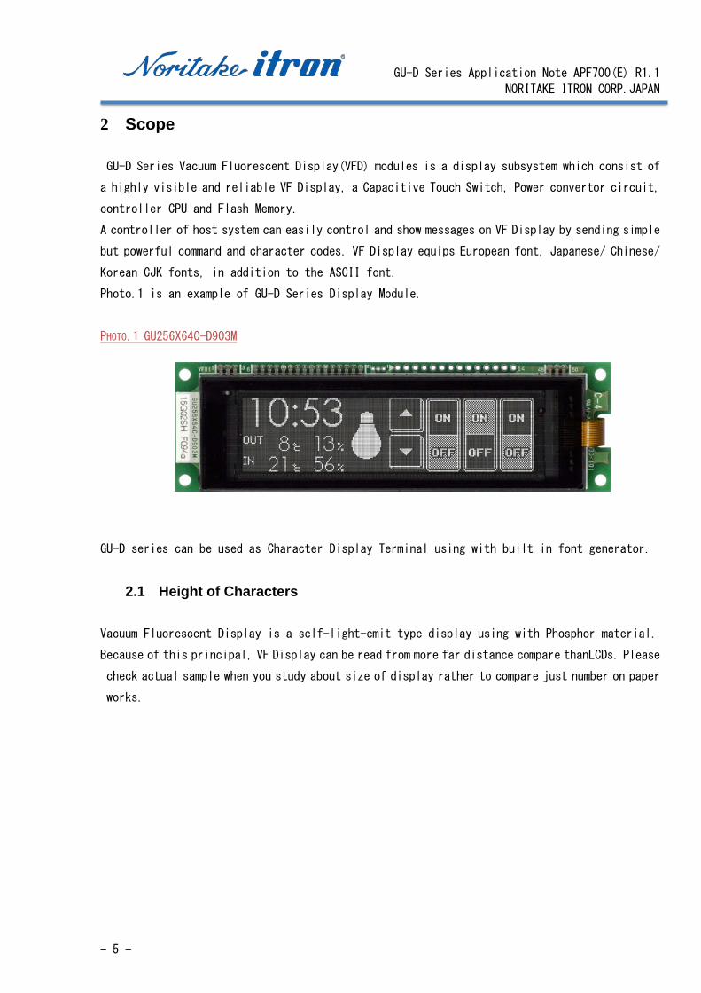
2 Scope
GU-D Series Vacuum Fluorescent Display(VFD) modules is a display subsystem which consist of
a highly visible and reliable VF Display, a Capacitive Touch Switch, Power convertor circuit,
controller CPU and Flash Memory.
A controller of host system can easily control and show messages on VF Display by sending simple
but powerful command and character codes. VF Display equips European font, Japanese/ Chinese/
Korean CJK fonts, in addition to the ASCII font.
Photo.1 is an example of GU-D Series Display Module.
PHOTO.1 GU256X64C-D903M
GU-D series can be used as Character Display Terminal using with built in font generator.
2.1 Height of Characters
Vacuum Fluorescent Display is a self-light-emit type display using with Phosphor material.
Because of this principal, VF Display can be read from more far distance compare thanLCDs. Please
check actual sample when you study about size of display rather to compare just number on paper
works.
GU-D Series Application Note APF700(E) R1.1
NORITAKE ITRON CORP.JAPAN
- 6 -
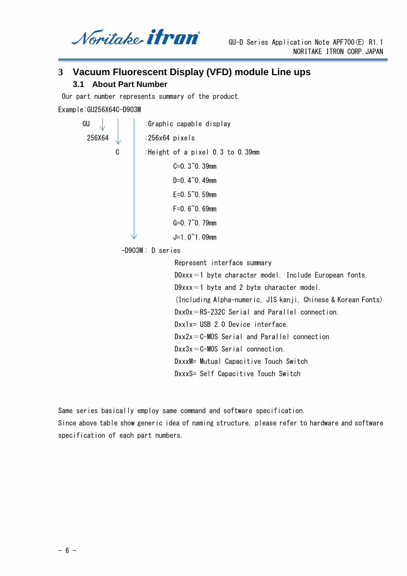
3 Vacuum Fluorescent Display (VFD) module Line ups 3.1 About Part Number
Our part number represents summary of the product.
Example:GU256X64C-D903M
GU :Graphic capable display
256X64 :256x64 pixels
C :Height of a pixel 0.3 to 0.39mm
C=0.3~0.39mm
D=0.4~0.49mm
E=0.5~0.59mm
F=0.6~0.69mm
G=0.7~0.79mm
J=1.0~1.09mm
-D903M : D series
Represent interface summary
D0xxx=1 byte character model. Include European fonts.
D9xxx=1 byte and 2 byte character model.
(Including Alpha-numeric, JIS kanji, Chinese & Korean Fonts)
Dxx0x=RS-232C Serial and Parallel connection.
Dxx1x= USB 2.0 Device interface.
Dxx2x=C-MOS Serial and Parallel connection
Dxx3x=C-MOS Serial connection.
DxxxM= Mutual Capacitive Touch Switch
DxxxS= Self Capacitive Touch Switch
Same series basically employ same command and software specification.
Since above table show generic idea of naming structure, please refer to hardware and software
specification of each part numbers.
GU-D Series Application Note APF700(E) R1.1
NORITAKE ITRON CORP.JAPAN
- 7 -
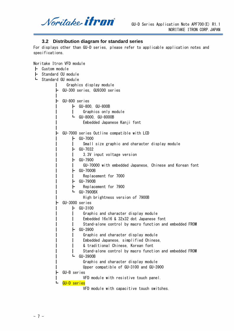
3.2 Distribution diagram for standard series For displays other than GU-D series, please refer to applicable application notes and
specifications.
Noritake Itron VFD module
┣ Custom module
┣ Standard CU module
┗ Standard GU module
┃ Graphics display module
┣ GU-300 series, GU9300 series
┃
┣ GU-800 series
┃ ┣ GU-800, GU-800B
┃ ┃ Graphics only module
┃ ┗ GU-8000, GU-8000B
┃ Embedded Japanese Kanji font
┃
┣ GU-7000 series Outline compatible with LCD
┃ ┣ GU-7000
┃ ┃ Small size graphic and character display module
┃ ┣ GU-7032
┃ ┃ 3.3V input voltage version
┃ ┣ GU-7900
┃ ┃ GU-70000 with embedded Japanese, Chinese and Korean font
┃ ┣ GU-7000B
┃ ┃ Replacement for 7000
┃ ┣ GU-7900B
┃ ┣ Replacement for 7900
┃ ┗ GU-7900BX
┃ High brightness version of 7900B
┣ GU-3000 series
┃ ┣ GU-3100
┃ ┃ Graphic and character display module
┃ ┃ Embedded 16x16 & 32x32 dot Japanese font
┃ ┃ Stand-alone control by macro function and embedded FROM
┃ ┣ GU-3900
┃ ┃ Graphic and character display module
┃ ┃ Embedded Japanese, simplified Chinese,
┃ ┃ & traditional Chinese, Korean font
┃ ┃ Stand-alone control by macro function and embedded FROM
┃ ┗ GU-3900B
┃ Graphic and character display module
┃ Upper compatible of GU-3100 and GU-3900
┣ GU-B series
┃ VFD module with resistive touch panel.
┗ GU-D series
VFD module with capacitive touch switches.
GU-D Series Application Note APF700(E) R1.1
NORITAKE ITRON CORP.JAPAN
- 8 -
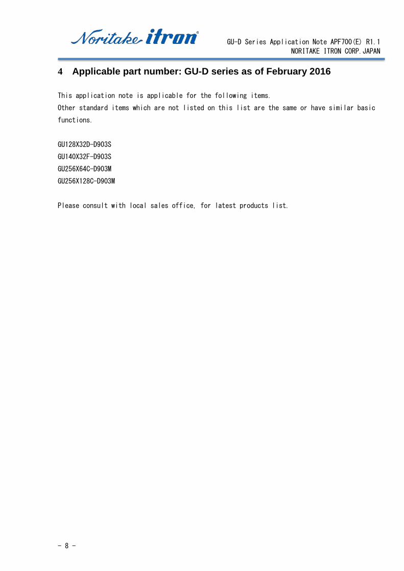
4 Applicable part number: GU-D series as of February 2016
This application note is applicable for the following items.
Other standard items which are not listed on this list are the same or have similar basic
functions.
GU128X32D-D903S
GU140X32F-D903S
GU256X64C-D903M
GU256X128C-D903M
Please consult with local sales office, for latest products list.
GU-D Series Application Note APF700(E) R1.1
NORITAKE ITRON CORP.JAPAN
- 9 -
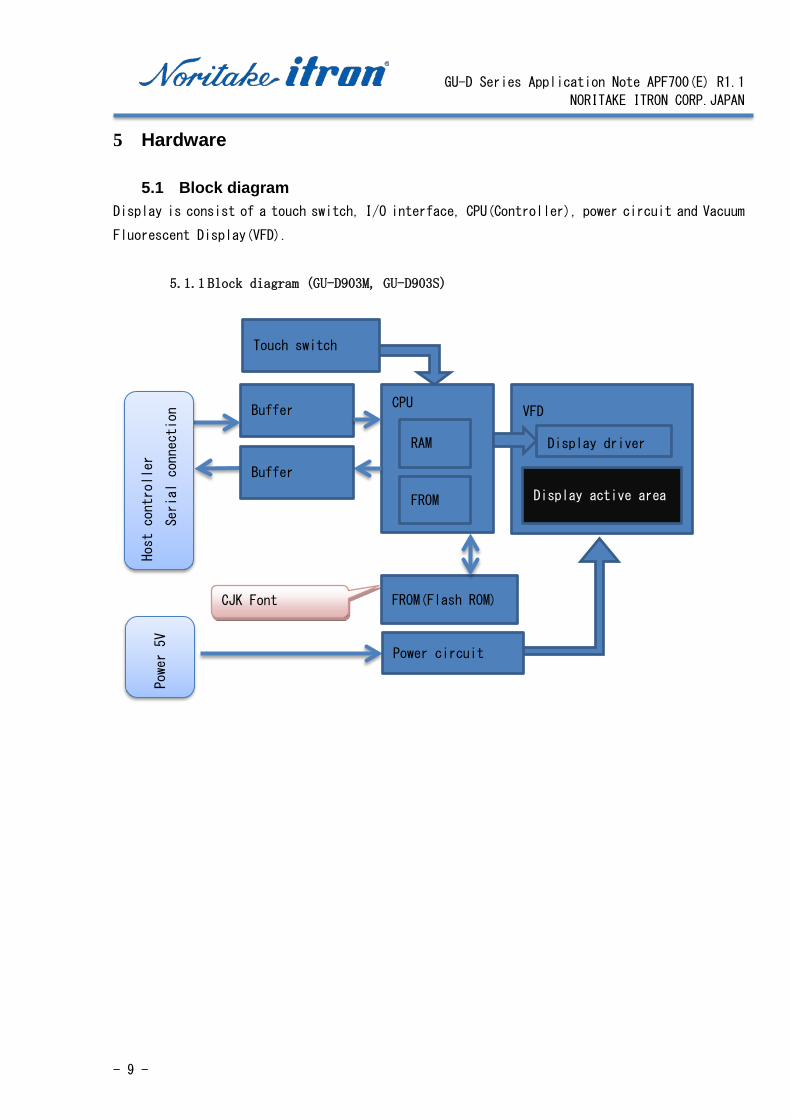
5 Hardware
5.1 Block diagram Display is consist of a touch switch, I/O interface, CPU(Controller), power circuit and Vacuum
Fluorescent Display(VFD).
5.1.1 Block diagram (GU-D903M, GU-D903S)
CJK Font
Buffer CPU
FROM
RAM
VFD
Display driver
Display active area
Buffer
Host controller
Serial connection
FROM(Flash ROM)
Power circuit
Power 5V
Touch switch

GU-D Series Application Note APF700(E) R1.1
NORITAKE ITRON CORP.JAPAN
- 10 -
5.2 Touch Switch 5.2.2 Pprinciple
There are 2 type of switches. One is self-capacitive. Other is mutual capacitive.
Self-capacitive touch switch
One switch consists of one electrode. Increase of capacitance by a touch is detected by touch
sensor.
Circuit without touch Circuit with touch
Total capacitance is increased by additional stray capacity of touching operator.
Mutual capacitive touch switch
One switch consists of two electrodes. A sensor detects electric field between two electrodes.
Circuit without touch Circuit with touch
Sensor detects change of electric field between electrodes.
Stray capacity Stray capacity of electrode
Stray capacity
of Body Capacitance between
body and electrode
Sensor Signal
Sensor Signal
Receiver Transmitter
GU-D Series Application Note APF700(E) R1.1
NORITAKE ITRON CORP.JAPAN
- 11 -
5.2.3 Merit of Noritake Touch Switch Noritake touch switches have following merits.
* No wear and tear. No life limitation by mechanical cause.
* Space saving design is achieved by switches located on display area.
* Glass base and Aluminum thin film technology have made low impedance and high transparent
switches possible.
*Mutual touch has water drop resistance. More stable operation is achieved under water
spit condition.
* Mutual touch switch achieves high sensitivity, and can be covered by glass or acrylic
window.
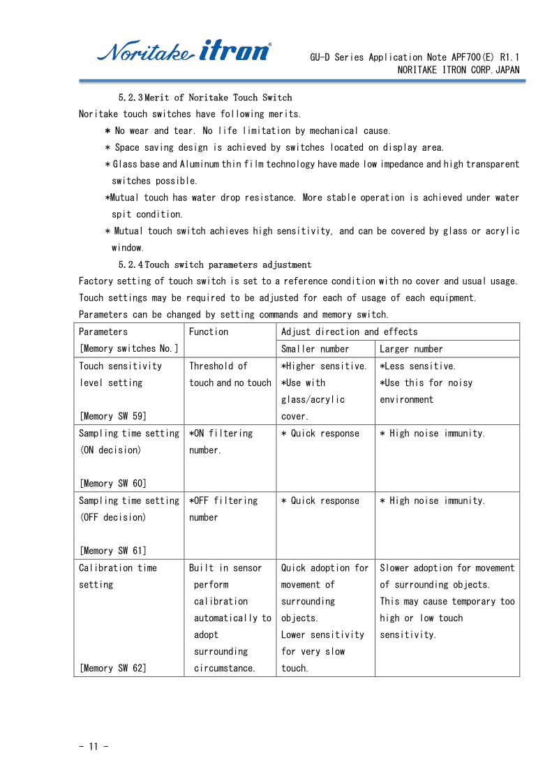
5.2.4 Touch switch parameters adjustment Factory setting of touch switch is set to a reference condition with no cover and usual usage.
Touch settings may be required to be adjusted for each of usage of each equipment.
Parameters can be changed by setting commands and memory switch.
Parameters
[Memory switches No.]
Function Adjust direction and effects
Smaller number Larger number
Touch sensitivity
level setting
[Memory SW 59]
Threshold of
touch and no touch
*Higher sensitive.
*Use with
glass/acrylic
cover.
*Less sensitive.
*Use this for noisy
environment
Sampling time setting
(ON decision)
[Memory SW 60]
*ON filtering
number.
* Quick response * High noise immunity.
Sampling time setting
(OFF decision)
[Memory SW 61]
*OFF filtering
number
* Quick response * High noise immunity.
Calibration time
setting
[Memory SW 62]
Built in sensor
perform
calibration
automatically to
adopt
surrounding
circumstance.
Quick adoption for
movement of
surrounding
objects.
Lower sensitivity
for very slow
touch.
Slower adoption for movement
of surrounding objects.
This may cause temporary too
high or low touch
sensitivity.

GU-D Series Application Note APF700(E) R1.1
NORITAKE ITRON CORP.JAPAN
- 12 -
5.2.5 Case study of adjustment
Fast touch, add glass or acrylic overlay
Parameters Direction
Touch sensitivity level setting Lower number
Sampling time setting (ON decision) Lower number
Sampling time setting (OFF decision) Lower number
Calibration time setting Depend on equipment
Use “Long touch”(Does not response short touch)
Parameter Direction
Touch sensitivity level setting Larger number
Sampling time setting (ON decision) Larger number
Sampling time setting (OFF decision) Larger number
Calibration time setting Depend on equipment
5.2.6 Recommended configuration
For detailed recommended configuration, please refer to applicable technical note.
5.2.7 Touch switch read setting(Refer to Memory SW 63 and Touch-Switch command group.
Touch sensor output can be gotten in variety of formats.
Type of data can be read
ON/OFF
Touch switch count level
Touch switch touch level
ON/OFF
Read if current status is ON or OFF. All switches can be read in 2 or 4 byte format, or read
individual switch. Automated output when touch or leave is also available.
GU-D Series Application Note APF700(E) R1.1
NORITAKE ITRON CORP.JAPAN
- 13 -
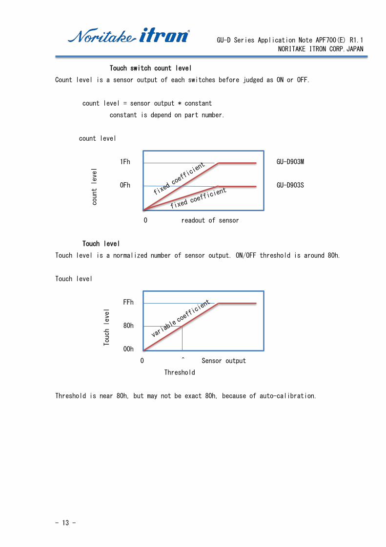
Touch switch count level
Count level is a sensor output of each switches before judged as ON or OFF.
count level = sensor output * constant
constant is depend on part number.
count level
1Fh GU-D903M
0Fh GU-D903S
0 readout of sensor
Touch level
Touch level is a normalized number of sensor output. ON/OFF threshold is around 80h.
Touch level
FFh
80h
00h
0 ^ Sensor output
Threshold
Threshold is near 80h, but may not be exact 80h, because of auto-calibration.
count level
Touch level
GU-D Series Application Note APF700(E) R1.1
NORITAKE ITRON CORP.JAPAN
- 14 -
5.3 Connector GU-D series does not equip interface connectors, but just through holes. Please solder
suitable connector such as post header.
GU-D series is not compatible with reflow soldering.
5.4 Host interface, GPIO
Signal level is 3.3V C-MOS. Do not apply 5V signals.
Host interface can be selected from one of UART, SPI and I2C, according to jumper setting.
Factory setting is UART.
A soldering is required to change the Jumper setting.
GU-D Series Application Note APF700(E) R1.1
NORITAKE ITRON CORP.JAPAN
- 15 -
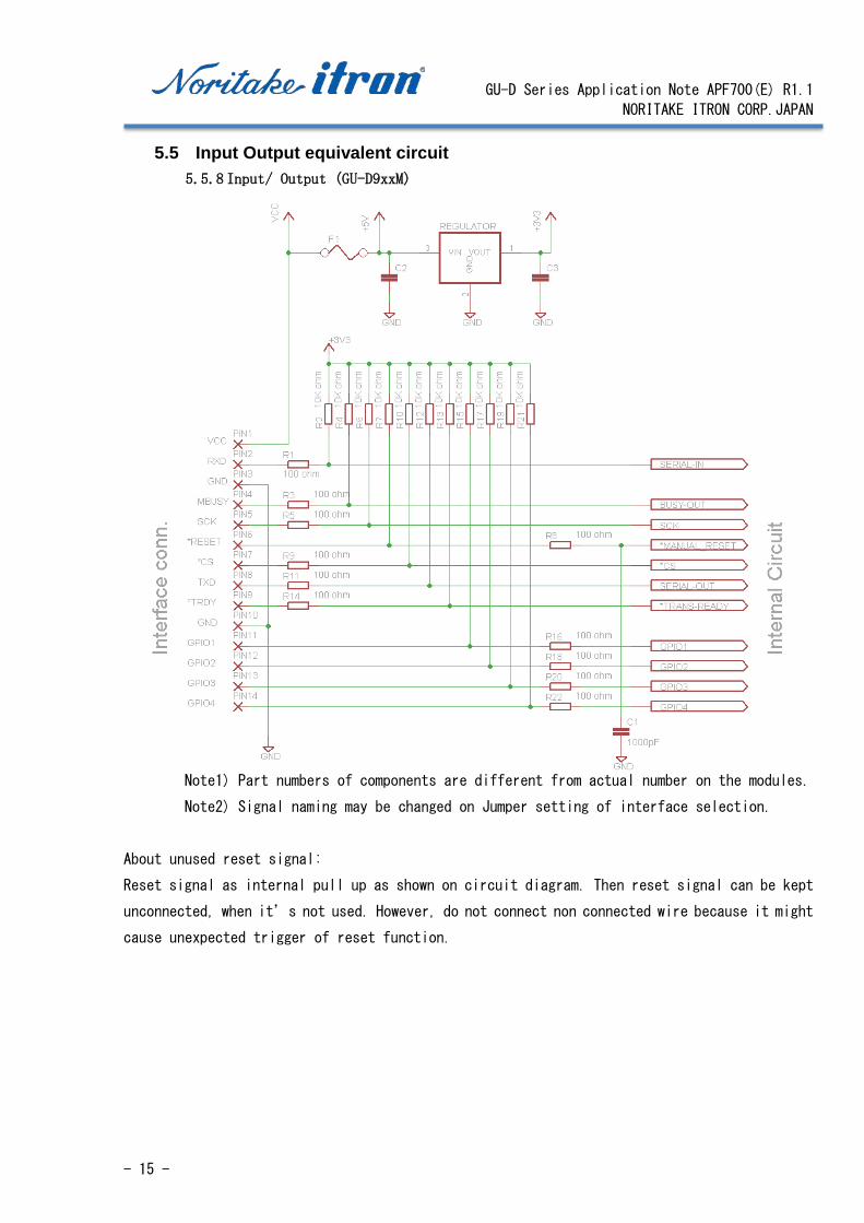
5.5 Input Output equivalent circuit 5.5.8 Input/ Output (GU-D9xxM)
Note1) Part numbers of components are different from actual number on the modules.
Note2) Signal naming may be changed on Jumper setting of interface selection.
About unused reset signal:
Reset signal as internal pull up as shown on circuit diagram. Then reset signal can be kept
unconnected, when it’s not used. However, do not connect non connected wire because it might
cause unexpected trigger of reset function.

GU-D Series Application Note APF700(E) R1.1
NORITAKE ITRON CORP.JAPAN
- 16 -
5.5.9 Input/ Output (GU-D9xxS)
Note1) Part numbers of components are different from actual number on the modules.
Note2) Signal naming may be changed on Jumper setting of interface selection.
About unused reset signal:
Reset signal as internal pull up as shown on circuit diagram. Then reset signal can be kept
unconnected, when it’s not used. However, do not connect non connected wire because it might
cause unexpected trigger of reset function.
GU-D Series Application Note APF700(E) R1.1
NORITAKE ITRON CORP.JAPAN
- 17 -
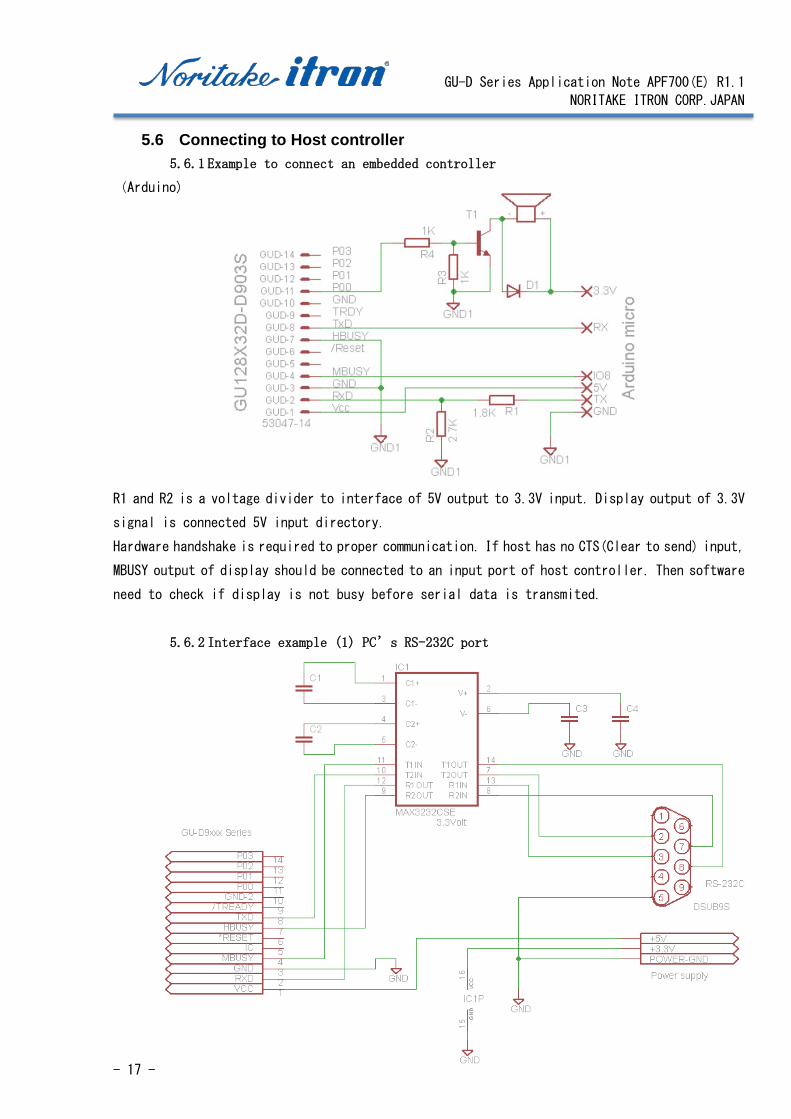
5.6 Connecting to Host controller 5.6.1 Example to connect an embedded controller
(Arduino)
R1 and R2 is a voltage divider to interface of 5V output to 3.3V input. Display output of 3.3V
signal is connected 5V input directory.
Hardware handshake is required to proper communication. If host has no CTS(Clear to send) input,
MBUSY output of display should be connected to an input port of host controller. Then software
need to check if display is not busy before serial data is transmited.
5.6.2 Interface example (1) PC’s RS-232C port

GU-D Series Application Note APF700(E) R1.1
NORITAKE ITRON CORP.JAPAN
- 18 -
5.6.3 Interface example (2) PC’s RS-232C port
5.6.4 Interface example (1) PC’s USB-Serial(3.3V) adopter

GU-D Series Application Note APF700(E) R1.1
NORITAKE ITRON CORP.JAPAN
- 19 -
6 Software 6.1 Initialization and protocol
Communication protocol is no-protocol with hardware hand shake.
Controller can start display basic information without complicated initialization, because of
factory settings are prepared. To start with GU-D series, wait several hundred millisecond for
power up, then send ASCII character codes. Then try to send ESC sequence to call special settings
and functions.
6.2 Settings other than default GU-D series equips memory switches to customize power on default settings. UART baud rate can
be changed by a jumper setting (soldering is required). Other settings can be changed by memory
switches or commands.
Memory switch
Parameters Function Factory setting
Power-on FROM macro
automatic execute
Program macro or macro in
FROM is executed at power on.
Do not execute
I2C slave address setting Slave address of
I2Cinterface
00h
Asynchronous serial baud
rate setting
Set serial bit rate. To
activate memory switch
setting, a jumper
change(soldering is
required) is required.
00h:115200BPS
Factory setting is
38400BPSby jumper.
Asynchronous serial parity
setting
Set parity bit. 00h: none parity
Touch sensitivity level
setting
Set threshold of touch 07:100%
Sampling time setting (ON
decision)
Filtering number of ON
judgement
3
Sampling time setting (OFF
decision)
Filtering number of OFF
judgement
6
Calibration time setting Set interval of auto
calibration
10
Touch switch read setting Touch data
auto-transmission by touch
or release.
00h: By command only

GU-D Series Application Note APF700(E) R1.1
NORITAKE ITRON CORP.JAPAN
- 20 -
6.3 Memory Here is a table of user accessible memories.
Name Type of memory Capacity Note
GU128X32
GU140X32
GU256X64
GU256X128
Display memory RAM 2,048 Byte 8,192 Byte Refer to
”Display memory”
Bit image memory FROM(Flash ROM) 524,288 Byte
Macro memory RAM 256 Byte Store macro and program
macro. FROM(Flash ROM) 32,768 Byte
(8,192 Byte X4)
Download
character
RAM 16 characters One byte character font
modification.
Memory switch FROM 64 Byte Set power on settings.
Refer to
“Settings other than
default”
6.3.1 Display memory (RAM) Written data is processed and transformed to graphics image, and stored into Display memory.
Because display memory capacity is larger than number of pixels on screen, part of display memory
contents are shown on screen. Then the display memory is divided into “display area” and
“hidden area”.
RAM
Hidden area can be used as work space to prepare display screen.
非表示エリア Hidden area Display area

GU-D Series Application Note APF700(E) R1.1
NORITAKE ITRON CORP.JAPAN
- 21 -
6.4 Proportional font
Proportional font is trimed character on
screen by removing unnecessary space between
characters.
With this function, number of characters on
screen could be increased.
This function is valid for one byte code only.
6.5 Embedded font
GU-D9 series has following 2 byte character tables.
Part number
GU128X32D-D903S,
GU140X32F-D903S,
GU256X64C-D903M,
GU256X128C-D903M
Font tables: 5x7dot ANK & International,
16x16dot JIS, Simplified and Traditional Chinese, Korean
GU-D Series Application Note APF700(E) R1.1
NORITAKE ITRON CORP.JAPAN
- 22 -
6.6 Font table Concept is described in this section. Detailed information is available on individual
specifications.
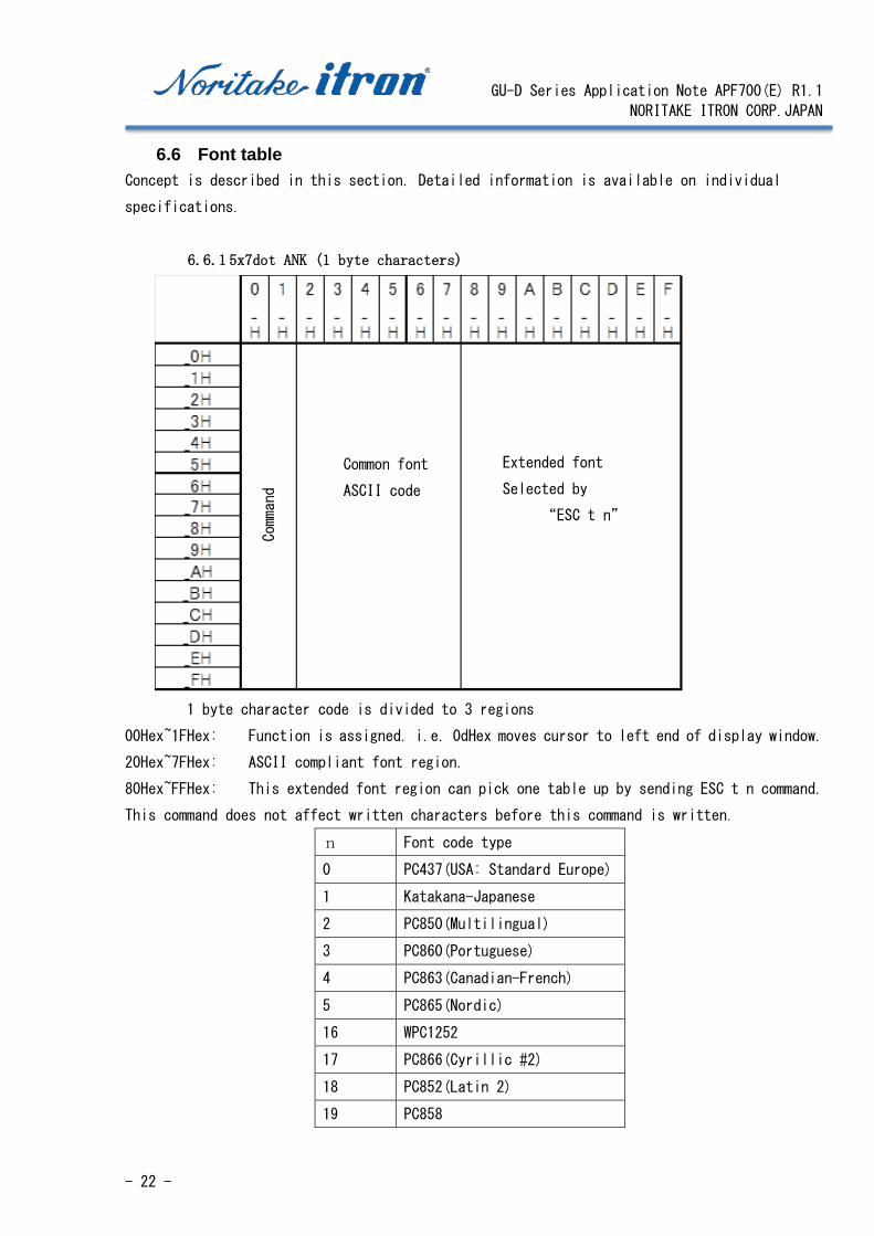
6.6.1 5x7dot ANK (1 byte characters)
1 byte character code is divided to 3 regions
00Hex~1FHex: Function is assigned. i.e. 0dHex moves cursor to left end of display window.
20Hex~7FHex: ASCII compliant font region.
80Hex~FFHex: This extended font region can pick one table up by sending ESC t n command.
This command does not affect written characters before this command is written.
n Font code type
0 PC437(USA: Standard Europe)
1 Katakana-Japanese
2 PC850(Multilingual)
3 PC860(Portuguese)
4 PC863(Canadian-French)
5 PC865(Nordic)
16 WPC1252
17 PC866(Cyrillic #2)
18 PC852(Latin 2)
19 PC858
Command
Common font
ASCII code
Extended font
Selected by
“ESC t n”
GU-D Series Application Note APF700(E) R1.1
NORITAKE ITRON CORP.JAPAN
- 23 -
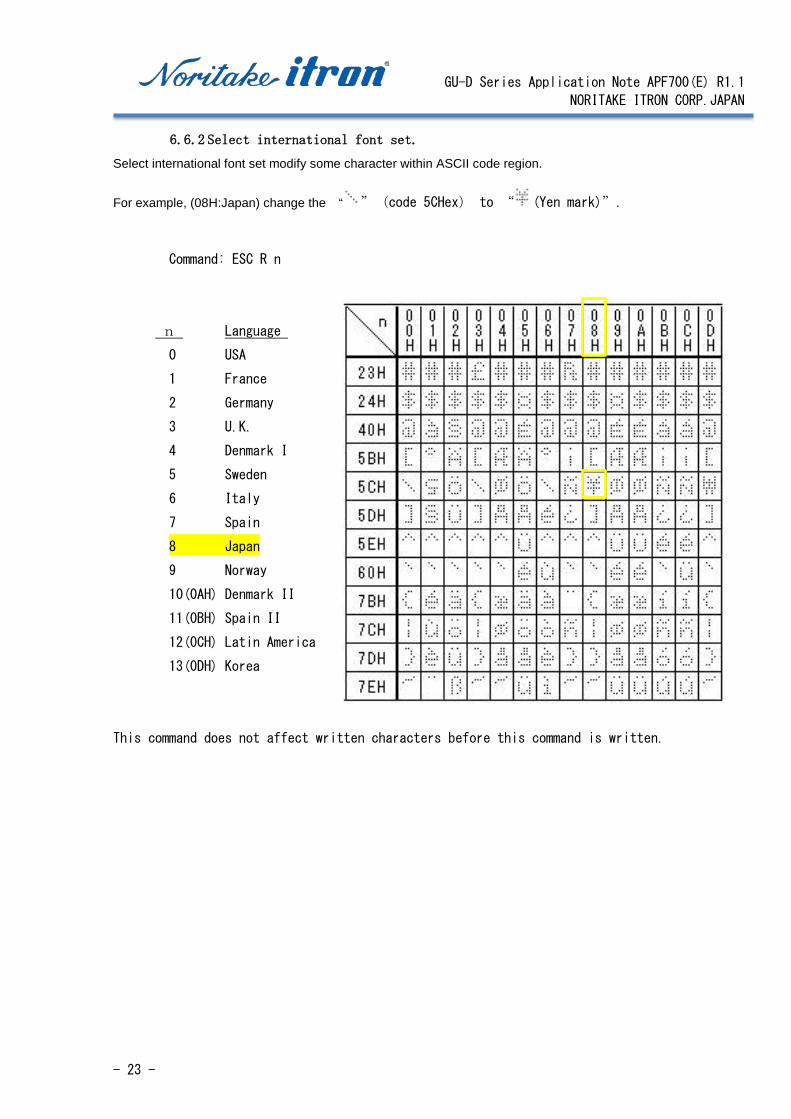
6.6.2 Select international font set. Select international font set modify some character within ASCII code region.
For example, (08H:Japan) change the “ ”(code 5CHex) to “ (Yen mark)”.
Command: ESC R n
n Language
0 USA
1 France
2 Germany
3 U.K.
4 Denmark I
5 Sweden
6 Italy
7 Spain
8 Japan
9 Norway
10(0AH) Denmark II
11(0BH) Spain II
12(0CH) Latin America
13(0DH) Korea
This command does not affect written characters before this command is written.

GU-D Series Application Note APF700(E) R1.1
NORITAKE ITRON CORP.JAPAN
- 24 -
6.6.3 16x16dot JIS, Simplified Chinese, Traditional Chinese, Korean (GU-D9xxx) (2 byte characters)
GU-D9xxx equips 16x16 dot font generator.
In order to call 2 byte code characters, a set of commands need to be given.
Because written characters are not changed by set up command, series of characters from different
table can be shown on same screen at same time.
2 byte code set up command
Set up JIS Kanji
1FH, 28H, 67H, 01H, 02H ‘ 8x16 dot font
1FH, 28H, 67H, 02H, 01H ‘ 2 byte character mode on
1FH, 28H, 67H, 0FH, 00H ‘ 2 byte character type select: Japanese
88H, A2H ‘ Show
Set up Korean
1FH, 28H, 67H, 01H, 02H ‘ 8x16 dot font
1FH, 28H, 67H, 02H, 01H ‘ 2 byte character mode on
1FH, 28H, 67H, 0FH, 01H ‘ 2 byte character type select: Korean
Write character
Set up Simplified Chinese
1FH, 28H, 67H, 01H, 02H ‘ 8x16 dot font
1FH, 28H, 67H, 02H, 01H ‘ 2 byte character mode on
1FH, 28H, 67H, 0FH, 02H ‘ 2 byte character type select: Korean
Write character
Set up Traditional Chinese
1FH, 28H, 67H, 01H, 02H ‘ 8x16 dot font
1FH, 28H, 67H, 02H, 01H ‘ 2 byte character mode on
1FH, 28H, 67H, 0FH, 03H ‘ 2 byte character type select: Korean
Write character

GU-D Series Application Note APF700(E) R1.1
NORITAKE ITRON CORP.JAPAN
- 25 -
Character code of each fonts are as follows;
Font Code Range of code
JIS kanji JISX208(Shift-JIS) 8140H~9FF0H, E040~EFFCH
Korean KSX5601-87 A1A1H~FEFEH
Simplified Chinese GB2312-80 A1A1H~FEFEH
Traditional Big-5 A140H~FEFEH
Sample of JIS Kanji Sample of Korean font
Sample of Simplified Chinese Sample of Traditional Chinese
For a full set of font data, please refer to font specification.

GU-D Series Application Note APF700(E) R1.1
NORITAKE ITRON CORP.JAPAN
- 26 -
6.7 Command table 6.7.1 Command table 1 Touch switch command group
Name code Function
All Touch-Switch
status read
1Fh 4Bh 10h Transmit On/Off status of all switches.
Individual
Touch-Switch
status read
1Fh 4Bh 11h sn Transmit on/off status of No. sn switch.
All Touch-Switch
count-level read
1Fh 4Bh 14h Transmit count level of all switches.
All Touch-Switch
touch-level read
1Fh 4Bh 15h Transmit touch level (normalized value) of all
switches.
Touch-Switch
status read mode
setting
1Fh 4Bh 18h m Set touch status read action.
m=0: Transmit by command.
m=1: Transmit all switch status by touch or leave.
m=2: Transmit individual status by touch or leave.
Touch-Switch
internal
parameters change
1Fh 4Bh 70h a b Set value b to parameter a.
a=0: Touch sensitivity level
a=1: Sampling time setting (ON decision)
a=2: Sampling time setting (OFF decision)
a=3: Calibration period setting
6.7.2 Command table 2
Name Code Function
BS 08h Move cursor one character to left.
HT 09h Move cursor one character to right.
LF 0Ah Move cursor one line down.
HOM 0Bh Move cursor to top left corner of current window.
CR 0Dh Move cursor to left end of same line.
CLR 0Ch Clear screen and move cursor to top left corner.
ESC 1Bh Initiate extended command sequence.
US 1Fh Initiate extended command sequence.

GU-D Series Application Note APF700(E) R1.1
NORITAKE ITRON CORP.JAPAN
- 27 -
6.7.3 Command table 3 Extended command sequence Name Code Function
Initialize display 1Bh 40h Software Reset.
Jumper settings are not read.
Cursor set 1Fh 24h xL xH yL yH Move cursor to (x,y).
Cursor display ON/OFF 1Fh 43h n Select Cursor display ON or OFF.
n=0: Cursor display off.
n=1: Cursor display on.
Font Width setting 1Fh 28h 67h 03h w Set font width of one byte characters.
W=0: Fixed width of 1dot space.
=1: Fixed width of 2 dots space.
=2: Proportional font with 1 dot space.
=3: Proportional font with 2 dots spacing.
Font Magnification
Setting
1Fh 28h 67h 40h x y Multiply font size by x and y.
Download character
definition
1Bh 26h 01h C1 C2
[data]
Up to 16 of one-byte-character-fonts are stored
in RAM.
To show defined characters, enable download
character using with "Download character
ON/OFF" command. Then send character codes.
To redefine character font(s), delete
definition using with "Download character
delete" command. Then define the character.
Download character
delete
1Bh 3Fh a c Delete definition of download character font.
Download character
ON/OFF
1Bh 25h n Enable or disable display of download
characters.
n=0: Disable download characters
=1: Enable download characters
International font
select
1B 52h n Replace some ASCII characters with country
specific characters. Characters already
displayed are not changed by this command.
n Font set
00h America
01h France
02h Germany
03h England

GU-D Series Application Note APF700(E) R1.1
NORITAKE ITRON CORP.JAPAN
- 28 -
04h Denmark 1
05h Sweden
06h Italy
07h Spain 1
08h Japan
09h Norway
0Ah Denmark 2
0Bh Spain 2
0Ch Latin America
0Dh Korea
Character table type
select
1Bh 74h n Select Character table which assigned between
80h and FFh. Characters already displayed are
not changed by this command.
n Font code type
00h PC437(USA – Euro std.)
01h Katakana – Japanese
02h PC850 (Multilingual)
03h PC860 (Portuguese)
04h PC863 (Canadian-French)
05h PC865 (Nordic)
10h WPC1252
11h PC866 (Cyrillic #2)
12h PC852 (Latin 2)
13h PC858
Over-write mode 1Fh 01h Cursor mode set to Over-write mode.
This command has effect for the current window.
Vertical scroll mode 1Fh 02h Cursor mode set to Vertical scroll mode.
This command has effect for the current window.
Horizontal scroll mode 1Fh 03h Cursor mode set to Horizontal scroll mode.
This command has effect for the current window.
Horizontal scroll speed
setting
1Fh 73h n Set speed for Horizontal scroll mode.
Scroll speed is set by n.
n Speed
00h Instantaneous
01h IntTime / 2 dots
02h - 1Fh (n-1) × IntTime / dot
IntTime is around 14mSec and refer to software
specification.

GU-D Series Application Note APF700(E) R1.1
NORITAKE ITRON CORP.JAPAN
- 29 -
Reverse display setting 1Fh 72h n Set Reverse display mode ON or OFF for character
and image display. Changing this setting only
affects subsequent data. Content already
displayed are not changed.
n = 00h: Reverse OFF
n = 01h: Reverse ON
Write mixture display
mode
1Fh 77h n Specifies write mixture mode. Newly-written
characters and images are combined with current
display contents in Display Memory.
n = 00h: Normal display write
(not mixture display)
n = 01h: OR display write
n = 02h: AND display write
n = 03h: Exclusive-OR display write
Brightness level setting 1Fh 58h n Set display brightness level.
n Brightness level
01h 12.5 %
02h 25.0 %
03h 37.5 %
04h 50.0 %
05h 62.5 %
06h 75.0 %
07h 87.5 %
08h 100 %
Wait 1Fh 28h 61h 01h t Waits for the specified time (command and data
processing is stopped).
Wait time is specified by 't'.
Wait time = t × approximately 0.5s
Scroll display action 1Fh 28h 61h 10h wL
wH cL cH s
Shift the display screen.
・Horizontal scrolling is possible by specifying
as the shift byte count a multiple of Y bytes.
・Display switching is possible by specifying
shift byte count as X dots x Y bytes.
・Scroll speed is specified by 's'.
Scroll speed: s ×IntTime (approximately) /
shift
GU-D Series Application Note APF700(E) R1.1
NORITAKE ITRON CORP.JAPAN
- 30 -
IntTime is around 14mSec and refer to software
specification.
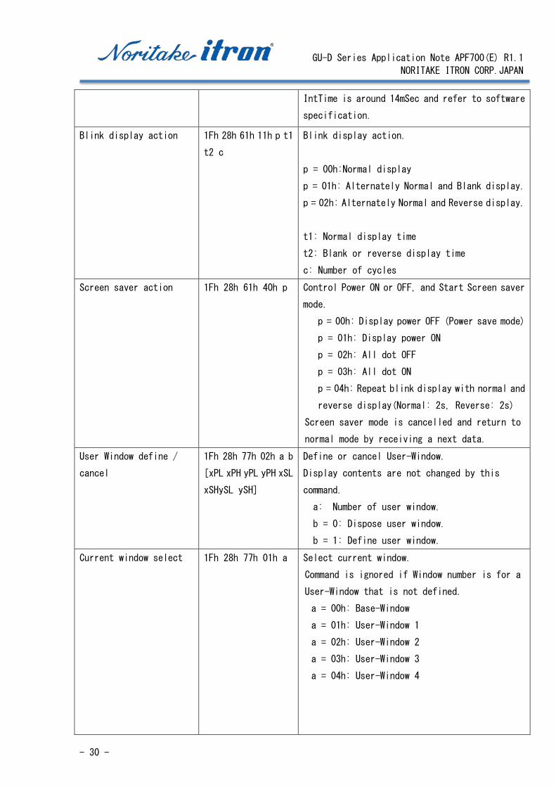
Blink display action 1Fh 28h 61h 11h p t1
t2 c
Blink display action.
p = 00h:Normal display
p = 01h: Alternately Normal and Blank display.
p = 02h: Alternately Normal and Reverse display.
t1: Normal display time
t2: Blank or reverse display time
c: Number of cycles
Screen saver action 1Fh 28h 61h 40h p Control Power ON or OFF, and Start Screen saver
mode.
p = 00h: Display power OFF (Power save mode)
p = 01h: Display power ON
p = 02h: All dot OFF
p = 03h: All dot ON
p = 04h: Repeat blink display with normal and
reverse display(Normal: 2s, Reverse: 2s)
Screen saver mode is cancelled and return to
normal mode by receiving a next data.
User Window define /
cancel
1Fh 28h 77h 02h a b
[xPL xPH yPL yPH xSL
xSHySL ySH]
Define or cancel User-Window.
Display contents are not changed by this
command.
a: Number of user window.
b = 0: Dispose user window.
b = 1: Define user window.
Current window select
1Fh 28h 77h 01h a Select current window.
Command is ignored if Window number is for a
User-Window that is not defined.
a = 00h: Base-Window
a = 01h: User-Window 1
a = 02h: User-Window 2
a = 03h: User-Window 3
a = 04h: User-Window 4
GU-D Series Application Note APF700(E) R1.1
NORITAKE ITRON CORP.JAPAN
- 31 -
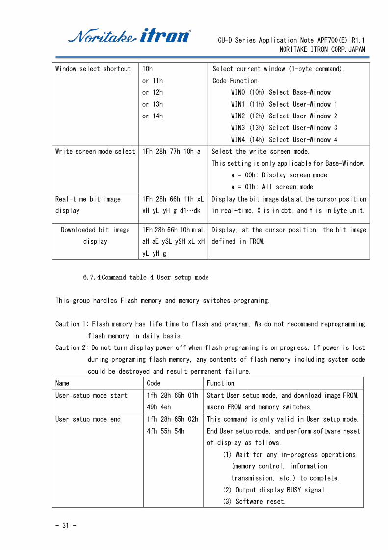
Window select shortcut 10h
or 11h
or 12h
or 13h
or 14h
Select current window (1-byte command).
Code Function
WIN0 (10h) Select Base-Window
WIN1 (11h) Select User-Window 1
WIN2 (12h) Select User-Window 2
WIN3 (13h) Select User-Window 3
WIN4 (14h) Select User-Window 4
Write screen mode select 1Fh 28h 77h 10h a Select the write screen mode.
This setting is only applicable for Base-Window.
a = 00h: Display screen mode
a = 01h: All screen mode
Real-time bit image
display
1Fh 28h 66h 11h xL
xH yL yH g d1…dk
Display the bit image data at the cursor position
in real-time. X is in dot, and Y is in Byte unit.
Downloaded bit image
display
1Fh 28h 66h 10h m aL
aH aE ySL ySH xL xH
yL yH g
Display, at the cursor position, the bit image
defined in FROM.
6.7.4 Command table 4 User setup mode
This group handles Flash memory and memory switches programing.
Caution 1: Flash memory has life time to flash and program. We do not recommend reprogramming
flash memory in daily basis.
Caution 2: Do not turn display power off when flash programing is on progress. If power is lost
during programing flash memory, any contents of flash memory including system code
could be destroyed and result permanent failure.
Name Code Function
User setup mode start 1fh 28h 65h 01h
49h 4eh
Start User setup mode, and download image FROM,
macro FROM and memory switches.
User setup mode end 1fh 28h 65h 02h
4fh 55h 54h
This command is only valid in User setup mode.
End User setup mode, and perform software reset
of display as follows:
(1) Wait for any in-progress operations
(memory control, information
transmission, etc.) to complete.
(2) Output display BUSY signal.
(3) Software reset.

GU-D Series Application Note APF700(E) R1.1
NORITAKE ITRON CORP.JAPAN
- 32 -
1. Jumper and Memory-SW settings are re-loaded.
2. Settings of general-purpose I/O ports are
reset.
3. Contents of transmit and receive buffer are
reset.
Memory SW setting 1fh 28h 65h 03h a
b
Set value b to Memory SW 'a'.
Memory SW data send 1fh 28h 65h 04h a Send the contents of Memory SW data.
FROM bit image definition 1fh 28h 65h 10h
aL aH aE sL sH sE
d(1) d(2)…d(s)
Define user bit image to the FROM.
・BUSY signal is output by the display module
during processing of this command. The host must
not transmit any data during this time.
FROM Macro define / delete 1fh 28h 65h 12h a
pL pH t1 t2 d(1)
d(2)…d(p)
Define or delete FROM Macro or FROM Program
Macro.
Display status send 1fh 28h 65h 40h a
[b c]
Send display status information.
a = 02h: Firmware version information
(b, c not used)
a = 10h: 2-byte character code information
(b, c not used)
a = 11h: Language type information
(b, c not used)
a = 20h: Memory checksum information
00h ≤ b ≤ FFh: Start address
(Effective address = b × 10000h)
00h ≤ c ≤ FFh: Data length
(Effective data length = c × 10000h)
a = 30h: Product type information
(b, c not used)
a = 40h: Display x dot information
(b, c not used)
a = 41h: Display y dot information
(b, c not used)
a = 50h: X direction switch number
information (b, c not used)
a = 51h: Y direction switch number
information (b, c not used)
GU-D Series Application Note APF700(E) R1.1
NORITAKE ITRON CORP.JAPAN
- 33 -
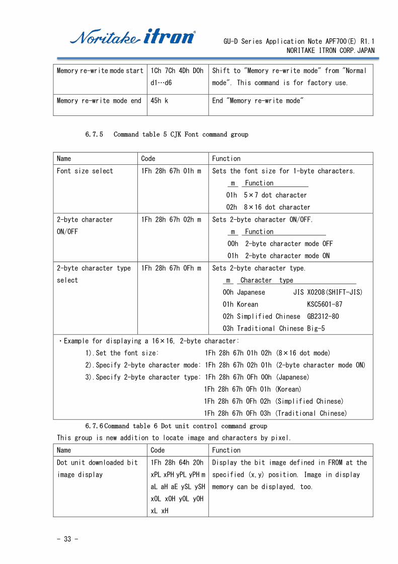
Memory re-write mode start 1Ch 7Ch 4Dh D0h
d1…d6
Shift to "Memory re-write mode" from "Normal
mode". This command is for factory use.
Memory re-write mode end 45h k End "Memory re-write mode"
6.7.5 Command table 5 CJK Font command group
Name Code Function
Font size select 1Fh 28h 67h 01h m Sets the font size for 1-byte characters.
m Function
01h 5×7 dot character
02h 8×16 dot character
2-byte character
ON/OFF
1Fh 28h 67h 02h m Sets 2-byte character ON/OFF.
m Function
00h 2-byte character mode OFF
01h 2-byte character mode ON
2-byte character type
select
1Fh 28h 67h 0Fh m Sets 2-byte character type.
m Character type
00h Japanese JIS X0208(SHIFT-JIS)
01h Korean KSC5601-87
02h Simplified Chinese GB2312-80
03h Traditional Chinese Big-5
・Example for displaying a 16×16, 2-byte character:
1).Set the font size: 1Fh 28h 67h 01h 02h (8×16 dot mode)
2).Specify 2-byte character mode: 1Fh 28h 67h 02h 01h (2-byte character mode ON)
3).Specify 2-byte character type: 1Fh 28h 67h 0Fh 00h (Japanese)
1Fh 28h 67h 0Fh 01h (Korean)
1Fh 28h 67h 0Fh 02h (Simplified Chinese)
1Fh 28h 67h 0Fh 03h (Traditional Chinese)
6.7.6 Command table 6 Dot unit control command group This group is new addition to locate image and characters by pixel.
Name Code Function
Dot unit downloaded bit
image display
1Fh 28h 64h 20h
xPL xPH yPL yPH m
aL aH aE ySL ySH
xOL xOH yOL yOH
xL xH
Display the bit image defined in FROM at the
specified (x,y) position. Image in display
memory can be displayed, too.

GU-D Series Application Note APF700(E) R1.1
NORITAKE ITRON CORP.JAPAN
- 34 -
Dot unit real-time bit
image display
1Fh 28h 64h 21h
xPL xPH yPL yPH
xL xH yL yH g
d(1)…d(k)
Display the bit image data at the specified
(x,y) position in real-time.
Dot unit character display 1Fh 28h 64h 30h
xPL xPH yPL yPH
00h bLen
d(1)…’d(bLen)
Display the specified text characters at the
specified (x,y) position.
The current settings for character size and
table type, etc are used (except character
magnification setting).
6.7.7 Command table 7 sequence Macro
Name Code Function
RAM Macro define /
delete
1fh 3ah pL pH d(1)
… d(p)
Define or delete RAM Macro or RAM Program Macro.
When pL = 00h and pH = 00h, Macro is deleted.
Note: For FROM Macro definition, please refer to
Table 4.
Macro execution 1fh 5eh a t1 t2 Execute contents of defined Macro 'a'.
a = 00h: Execute normal macro in RAM.
a = 01h: Execute normal macro in FROM1.
a = 02h: Execute normal macro in FROM2.
a = 03h: Execute normal macro in FROM3.
a = 04h: Execute normal macro in FROM3.
a = 80h: Execute program macro in RAM.
a = 81h: Execute program macro in FROM1.
a = 82h: Execute program macro in FROM2.
a = 83h: Execute program macro in FROM3.
a = 84h: Execute program macro in FROM4.
GU-D Series Application Note APF700(E) R1.1
NORITAKE ITRON CORP.JAPAN
- 35 -
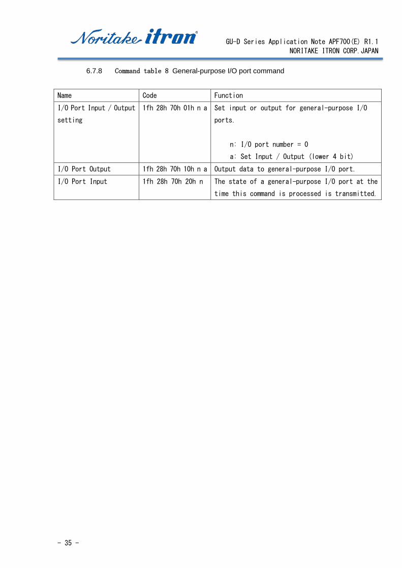
6.7.8 Command table 8 General-purpose I/O port command
Name Code Function
I/O Port Input / Output
setting
1fh 28h 70h 01h n a Set input or output for general-purpose I/O
ports.
n: I/O port number = 0
a: Set Input / Output (lower 4 bit)
I/O Port Output 1fh 28h 70h 10h n a Output data to general-purpose I/O port.
I/O Port Input 1fh 28h 70h 20h n The state of a general-purpose I/O port at the
time this command is processed is transmitted.

GU-D Series Application Note APF700(E) R1.1
NORITAKE ITRON CORP.JAPAN
- 36 -
6.8 Moving cursor and display mode This section describes the display mode of extended sequence commands.
Display mode specifies how to move a cursor at end of the line.
Over-write mode 1Fh 01h Over-writes, or replaces, existing data.
Vertical scroll mode 1Fh 02h Scrolls cursor up 1 line.
Horizontal scroll mode 1Fh 03h Scrolls cursor horizontally.
When a character is written, the character is displayed at the cursor position, and the cursor
moves forward one character.
For example, a motion of a cursor when written as"ABC" is as follows;
Before write in After write in
Display mode command affects next write-in operation.
Operation in each mode when written as "DEFGH" is as follows;
Overwrite mode: Return to the upper left and
“FGH” is over-written on “123”.
Vertical scroll mode: Scroll up entire screen
to make lowest line empty, then “FGH” is
written to the bottom line.
Horizontal scroll mode: Scroll the line to the
left. Scrolling speed can be specified in
another command. Scrolling will occur on any
line.
123
ABCDEFGH
123
|
123
ABC|
Cursor
FGH|
ABCDE|
ABCDE
FGH|
GU-D Series Application Note APF700(E) R1.1
NORITAKE ITRON CORP.JAPAN
- 37 -
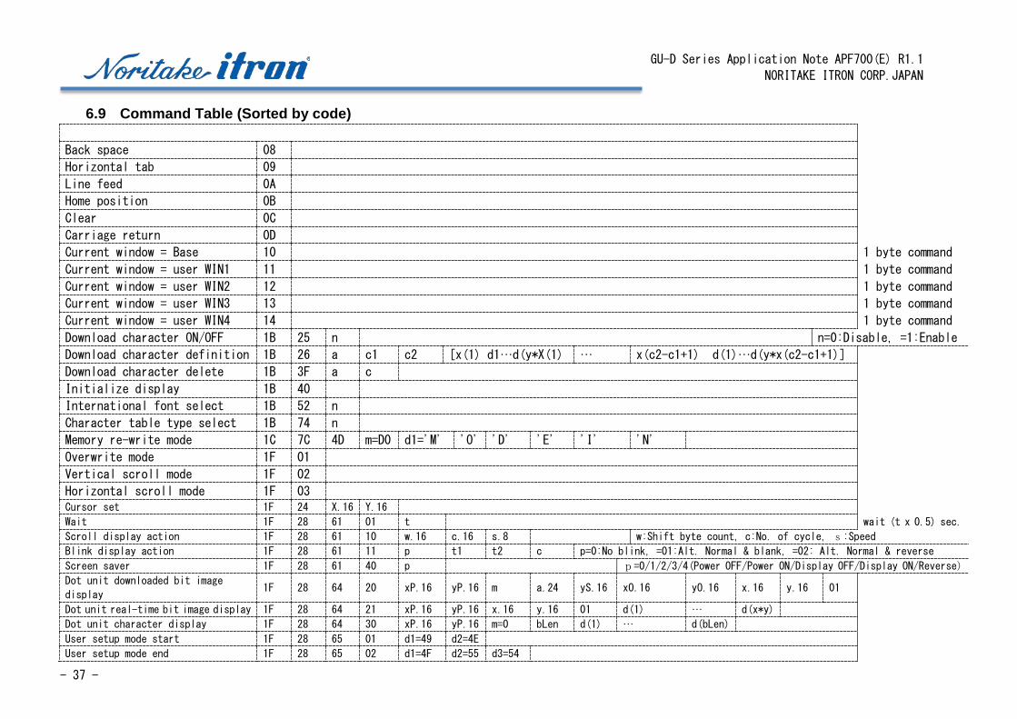
6.9 Command Table (Sorted by code)
Back space 08
Horizontal tab 09
Line feed 0A
Home position 0B
Clear 0C
Carriage return 0D
Current window = Base 10 1 byte command
Current window = user WIN1 11 1 byte command
Current window = user WIN2 12 1 byte command
Current window = user WIN3 13 1 byte command
Current window = user WIN4 14 1 byte command
Download character ON/OFF 1B 25 n n=0:Disable, =1:Enable
Download character definition 1B 26 a c1 c2 [x(1) d1…d(y*X(1) … x(c2-c1+1) d(1)…d(y*x(c2-c1+1)]
Download character delete 1B 3F a c
Initialize display 1B 40
International font select 1B 52 n
Character table type select 1B 74 n
Memory re-write mode 1C 7C 4D m=D0 d1='M' 'O' 'D' 'E' 'I' 'N'
Overwrite mode 1F 01
Vertical scroll mode 1F 02
Horizontal scroll mode 1F 03 Cursor set 1F 24 X.16 Y.16
Wait 1F 28 61 01 t wait (t x 0.5) sec.
Scroll display action 1F 28 61 10 w.16 c.16 s.8 w:Shift byte count, c:No. of cycle, s:Speed
Blink display action 1F 28 61 11 p t1 t2 c p=0:No blink, =01:Alt. Normal & blank, =02: Alt. Normal & reverse
Screen saver 1F 28 61 40 p p=0/1/2/3/4(Power OFF/Power ON/Display OFF/Display ON/Reverse)
Dot unit downloaded bit image
display 1F 28 64 20 xP.16 yP.16 m a.24 yS.16 xO.16 yO.16 x.16 y.16 01
Dot unit real-time bit image display 1F 28 64 21 xP.16 yP.16 x.16 y.16 01 d(1) … d(x*y)
Dot unit character display 1F 28 64 30 xP.16 yP.16 m=0 bLen d(1) … d(bLen)
User setup mode start 1F 28 65 01 d1=49 d2=4E
User setup mode end 1F 28 65 02 d1=4F d2=55 d3=54
GU-D Series Application Note APF700(E) R1.1
NORITAKE ITRON CORP.JAPAN
- 38 -
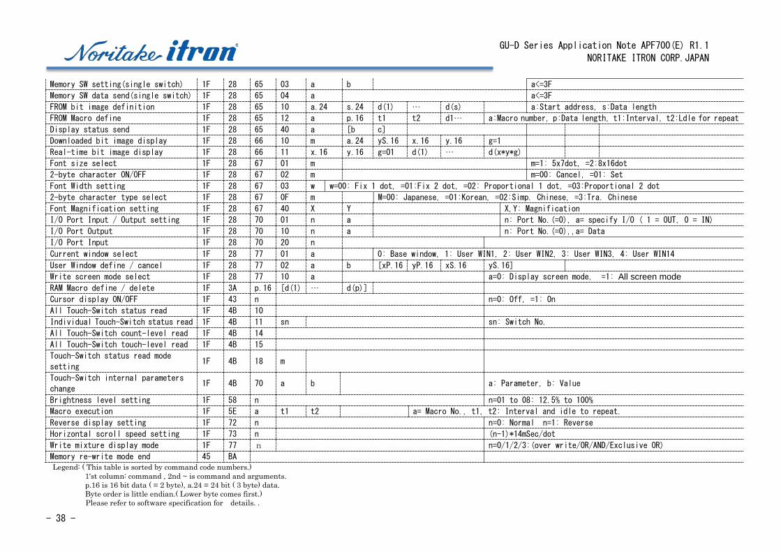
Memory SW setting(single switch) 1F 28 65 03 a b
a<=3F
Memory SW data send(single switch) 1F 28 65 04 a a<=3F
FROM bit image definition 1F 28 65 10 a.24 s.24 d(1) … d(s) a:Start address, s:Data length
FROM Macro define 1F 28 65 12 a p.16 t1 t2 d1… a:Macro number, p:Data length, t1:Interval, t2:Ldle for repeat
Display status send 1F 28 65 40 a [b c]
Downloaded bit image display 1F 28 66 10 m a.24 yS.16 x.16 y.16 g=1
Real-time bit image display 1F 28 66 11 x.16 y.16 g=01 d(1) … d(x*y*g)
Font size select 1F 28 67 01 m m=1: 5x7dot, =2:8x16dot
2-byte character ON/OFF 1F 28 67 02 m m=00: Cancel, =01: Set
Font Width setting 1F 28 67 03 w w=00: Fix 1 dot, =01:Fix 2 dot, =02: Proportional 1 dot, =03:Proportional 2 dot
2-byte character type select 1F 28 67 0F m
M=00: Japanese, =01:Korean, =02:Simp. Chinese, =3:Tra. Chinese
Font Magnification setting 1F 28 67 40 X Y
X,Y: Magnification
I/O Port Input / Output setting 1F 28 70 01 n a
n: Port No.(=0), a= specify I/O ( 1 = OUT, 0 = IN)
I/O Port Output 1F 28 70 10 n a
n: Port No.(=0),,a= Data
I/O Port Input 1F 28 70 20 n
Current window select 1F 28 77 01 a
0: Base window, 1: User WIN1, 2: User WIN2, 3: User WIN3, 4: User WIN14
User Window define / cancel 1F 28 77 02 a b [xP.16 yP.16 xS.16 yS.16]
Write screen mode select 1F 28 77 10 a
a=0: Display screen mode, =1: All screen mode RAM Macro define / delete 1F 3A p.16 [d(1) … d(p)]
Cursor display ON/OFF 1F 43 n
n=0: Off, =1: On
All Touch-Switch status read 1F 4B 10
Individual Touch-Switch status read 1F 4B 11 sn
sn: Switch No.
All Touch-Switch count-level read 1F 4B 14
All Touch-Switch touch-level read 1F 4B 15
Touch-Switch status read mode
setting 1F 4B 18 m
Touch-Switch internal parameters
change 1F 4B 70 a b
a: Parameter, b: Value
Brightness level setting 1F 58 n
n=01 to 08: 12.5% to 100%
Macro execution 1F 5E a t1 t2
a= Macro No., t1, t2: Interval and idle to repeat.
Reverse display setting 1F 72 n
n=0: Normal n=1: Reverse
Horizontal scroll speed setting 1F 73 n
(n-1)*14mSec/dot
Write mixture display mode 1F 77 n
n=0/1/2/3:(over write/OR/AND/Exclusive OR)
Memory re-write mode end 45 BA Legend: ( This table is sorted by command code numbers.)
1'st column: command , 2nd ~ is command and arguments. p.16 is 16 bit data ( = 2 byte), a.24 = 24 bit ( 3 byte) data. Byte order is little endian.( Lower byte comes first.) Please refer to software specification for details. .

GU-D Series Application Note APF700(E) R1.1
NORITAKE ITRON CORP.JAPAN
- 39 -
6.10 Program examples of Microsoft Visual Studio 2015 on Windows PC This is a sample program to display characters on GU-D series modules.
This sample can be run in C#2015 Community Edition.
6.10.1 Connect to serial port by Visual C# 2015
First of all, please connect GU-D series module to Windows PC using with serial port. If PC
does not have a serial port, USB-Serial adopter can be used. For the connecting circuit,
please refer to "Connecting to Host controller".
6.10.2 Verify connection [GU Tool Box]
We offer software to test connection and basic function of Noritake displays.
Please download [GU TOOL BOX] at Support software page.
Unzip file and just click application file in the folder. No installation is required. This
tool requires .Net Framework 4.0 or 4.5.
6.10.3 Serial access with Visual C#
First, install the C # 2015 from the site, Microsoft Corp.
Then Click "New Project...
GU-D Series Application Note APF700(E) R1.1
NORITAKE ITRON CORP.JAPAN
- 40 -
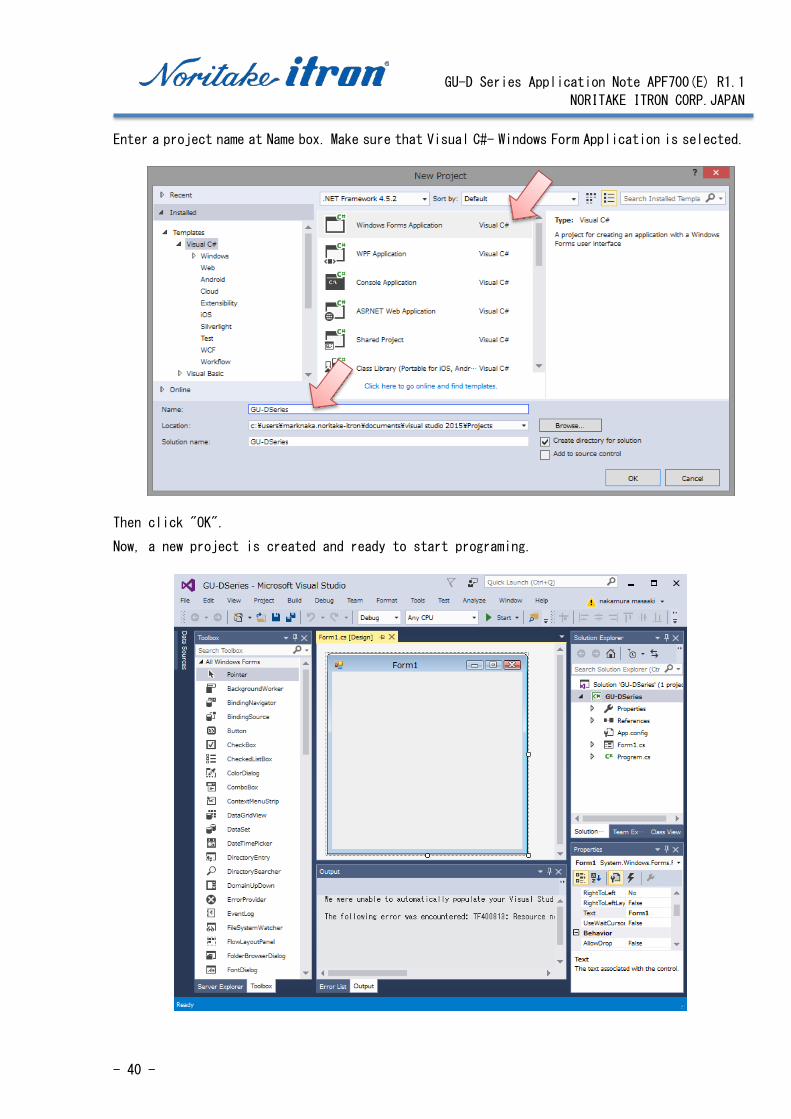
Enter a project name at Name box. Make sure that Visual C#- Windows Form Application is selected.
Then click "OK".
Now, a new project is created and ready to start programing.
GU-D Series Application Note APF700(E) R1.1
NORITAKE ITRON CORP.JAPAN
- 41 -
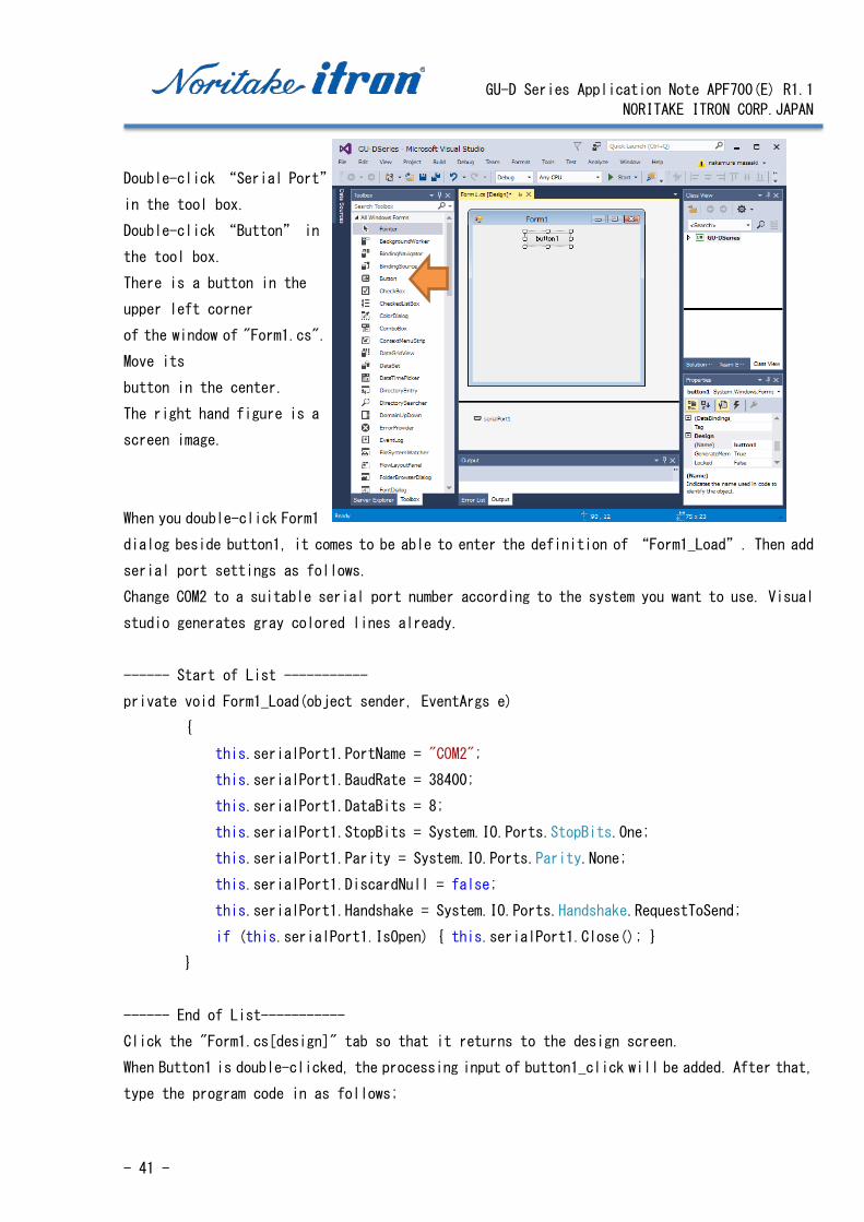
Double-click “Serial Port”
in the tool box.
Double-click “Button” in
the tool box.
There is a button in the
upper left corner
of the window of "Form1.cs".
Move its
button in the center.
The right hand figure is a
screen image.
When you double-click Form1
dialog beside button1, it comes to be able to enter the definition of “Form1_Load”. Then add
serial port settings as follows.
Change COM2 to a suitable serial port number according to the system you want to use. Visual
studio generates gray colored lines already.
------ Start of List -----------
private void Form1_Load(object sender, EventArgs e)
{
this.serialPort1.PortName = "COM2";
this.serialPort1.BaudRate = 38400;
this.serialPort1.DataBits = 8;
this.serialPort1.StopBits = System.IO.Ports.StopBits.One;
this.serialPort1.Parity = System.IO.Ports.Parity.None;
this.serialPort1.DiscardNull = false;
this.serialPort1.Handshake = System.IO.Ports.Handshake.RequestToSend;
if (this.serialPort1.IsOpen) { this.serialPort1.Close(); }
}
------ End of List-----------
Click the "Form1.cs[design]" tab so that it returns to the design screen.
When Button1 is double-clicked, the processing input of button1_click will be added. After that,
type the program code in as follows;
GU-D Series Application Note APF700(E) R1.1
NORITAKE ITRON CORP.JAPAN
- 42 -
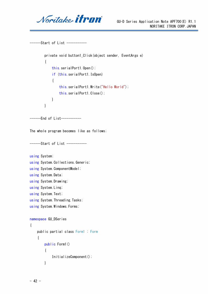
------Start of List -----------
private void button1_Click(object sender, EventArgs e)
{
this.serialPort1.Open();
if (this.serialPort1.IsOpen)
{
this.serialPort1.Write("Hello World");
this.serialPort1.Close();
}
}
------End of List-----------
The whole program becomes like as follows;
------Start of List -----------
using System;
using System.Collections.Generic;
using System.ComponentModel;
using System.Data;
using System.Drawing;
using System.Linq;
using System.Text;
using System.Threading.Tasks;
using System.Windows.Forms;
namespace GU_DSeries
{
public partial class Form1 : Form
{
public Form1()
{
InitializeComponent();
}
GU-D Series Application Note APF700(E) R1.1
NORITAKE ITRON CORP.JAPAN
- 43 -
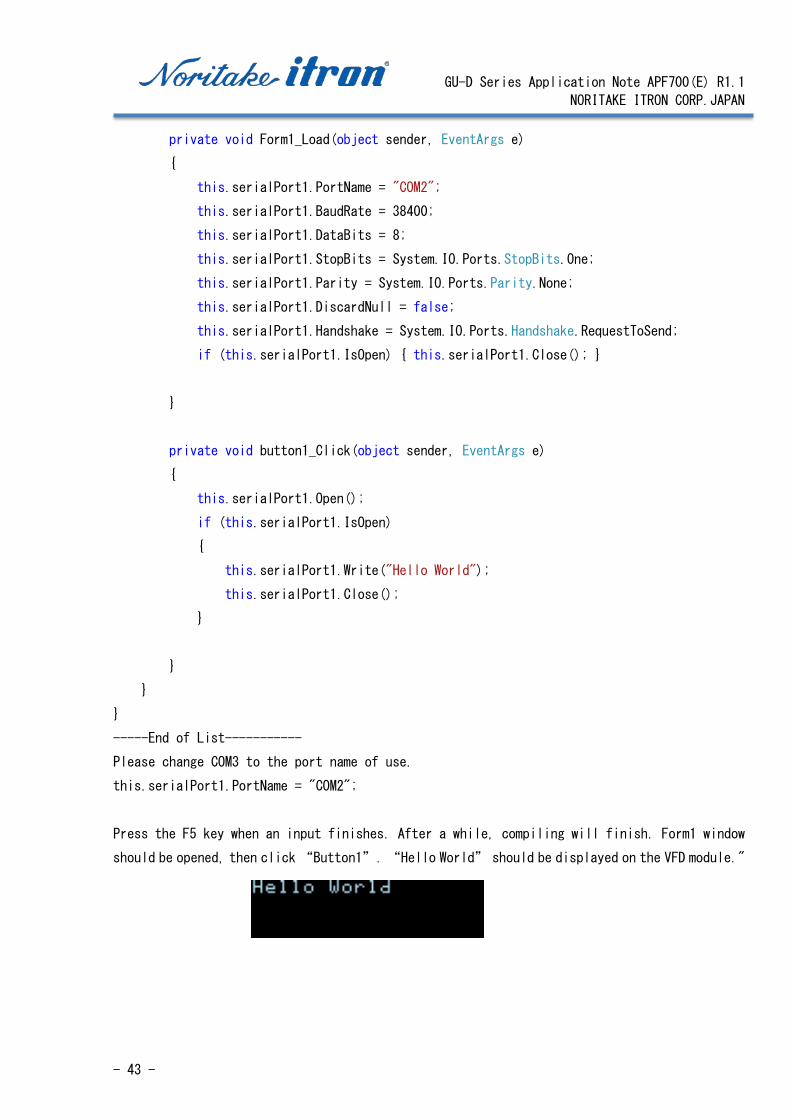
private void Form1_Load(object sender, EventArgs e)
{
this.serialPort1.PortName = "COM2";
this.serialPort1.BaudRate = 38400;
this.serialPort1.DataBits = 8;
this.serialPort1.StopBits = System.IO.Ports.StopBits.One;
this.serialPort1.Parity = System.IO.Ports.Parity.None;
this.serialPort1.DiscardNull = false;
this.serialPort1.Handshake = System.IO.Ports.Handshake.RequestToSend;
if (this.serialPort1.IsOpen) { this.serialPort1.Close(); }
}
private void button1_Click(object sender, EventArgs e)
{
this.serialPort1.Open();
if (this.serialPort1.IsOpen)
{
this.serialPort1.Write("Hello World");
this.serialPort1.Close();
}
}
}
}
-----End of List-----------
Please change COM3 to the port name of use.
this.serialPort1.PortName = "COM2";
Press the F5 key when an input finishes. After a while, compiling will finish. Form1 window
should be opened, then click “Button1”. “Hello World” should be displayed on the VFD module."
GU-D Series Application Note APF700(E) R1.1
NORITAKE ITRON CORP.JAPAN
- 44 -
6.11 Programing samples
The previous example explained how to display "Hello World" using C #.
This next example will show the various functions written in C #.
6.11.1 Clear Display
private void ClearScreen() {
byte[] bb = new byte[1];
bb[0] =(byte) 0x0c;
this.serialPort1.Open();
if (this.serialPort1.IsOpen) {
this.serialPort1.Write(bb, 0, 1);
this.serialPort1.Close(); }
}
6.11.2 Moving Cursor
A cursor moves to (int X, int Y). Please note that Y is in bytes. /* Move Cursot to (X, Y). Y is in Byte. */ private void moveCursor(int X, int Y)
{
byte[] bb = new byte[6];
bb[0] = (byte)0x1f;
bb[1] = (byte)0x24;
bb[2] = (byte)(X % 0x100);
bb[3] = (byte)(X / 0x100);
bb[4] = (byte)(Y % 0x100);
bb[5] = (byte)(Y / 0x100);
this.serialPort1.Open();
if (this.serialPort1.IsOpen)
{
this.serialPort1.Write(bb, 0, 6);
this.serialPort1.Close();
}
}
6.11.3 Magnified font
Magnified font is a function to enlarge a character to vertical and horizontal directions.
/* @Font Magnified */
private void fontMagnified(int X, int Y)
{
byte[] bb = new byte[6];

GU-D Series Application Note APF700(E) R1.1
NORITAKE ITRON CORP.JAPAN
- 45 -
bb[0] = (byte)0x1f;
bb[1] = (byte)0x28;
bb[2] = (byte)0x67;
bb[3] = (byte)0x40;
bb[4] = (byte)X;
bb[5] = (byte)Y;
this.serialPort1.Open();
if (this.serialPort1.IsOpen)
{
this.serialPort1.Write(bb, 0, 6);
this.serialPort1.Close();
}
}
6.11.4 Proportional ASCII
Change the character spacing. Using with a proportional font, the number of average characters which can be displayed will increase.
/* Set Font Size **
**
** w=0: Fixed Font Size with 1 dot space
** w=1: Fixed Font Size with 2 dot space
** w=2: Proportional Font Size with 1 dot space
** w=3: Proportional Font Size with 2 dot space
*/
private void FontWidth(int w)
{
byte[] bb = new byte[5];
bb[0] = (byte)0x1f;
bb[1] = (byte)0x28;
bb[2] = (byte)0x67;
bb[3] = (byte)0x03;
bb[4] = (byte)(w % 0x100);
this.serialPort1.Open();
if (this.serialPort1.IsOpen)

GU-D Series Application Note APF700(E) R1.1
NORITAKE ITRON CORP.JAPAN
- 46 -
{
this.serialPort1.Write(bb, 0, 5);
this.serialPort1.Close();
}
}
6.11.5 Set display 2-byte font
Set up CJK (Chinese-Japanese-Korean) font.
/* Setup Kanji
**
** Set up Kanji Display mode.
**
** cjk=0:Japanese,
** 1:Korean,
** 2:Simplified Chinese
** 3:Traditional Chinese
*/
private void CJK_setup( int cjk)
{
byte[] bb = new byte[15];
bb[0] = (byte)0x1f;
bb[1] = (byte)0x28;
bb[2] = (byte)0x67;
bb[3] = (byte)0x01;
bb[4] = (byte)0x02;
bb[5] = (byte)0x1f;
bb[6] = (byte)0x28;
bb[7] = (byte)0x67;
bb[8] = (byte)0x02;
bb[9] = (byte)0x01;
bb[10] = (byte)0x1f;
bb[11] = (byte)0x28;
bb[12] = (byte)0x67;
bb[13] = (byte)0x0f;
bb[14] = (byte)cjk;
GU-D Series Application Note APF700(E) R1.1
NORITAKE ITRON CORP.JAPAN
- 47 -
this.serialPort1.Open();
if (this.serialPort1.IsOpen)
{
this.serialPort1.Write(bb, 0, 15);
this.serialPort1.Close();
}
}
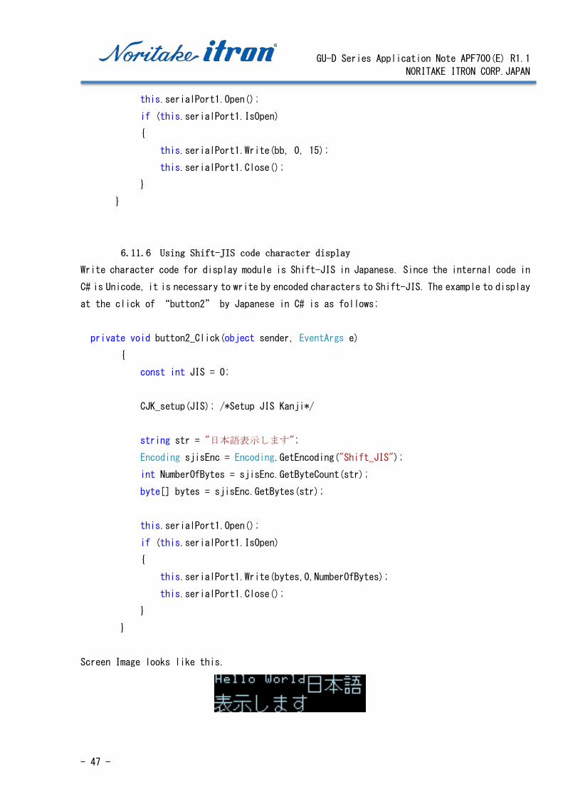
6.11.6 Using Shift-JIS code character display
Write character code for display module is Shift-JIS in Japanese. Since the internal code in
C# is Unicode, it is necessary to write by encoded characters to Shift-JIS. The example to display
at the click of “button2” by Japanese in C# is as follows;
private void button2_Click(object sender, EventArgs e)
{
const int JIS = 0;
CJK_setup(JIS); /*Setup JIS Kanji*/
string str = "日本語表示します";
Encoding sjisEnc = Encoding.GetEncoding("Shift_JIS");
int NumberOfBytes = sjisEnc.GetByteCount(str);
byte[] bytes = sjisEnc.GetBytes(str);
this.serialPort1.Open();
if (this.serialPort1.IsOpen)
{
this.serialPort1.Write(bytes,0,NumberOfBytes);
this.serialPort1.Close();
}
}
Screen Image looks like this.
GU-D Series Application Note APF700(E) R1.1
NORITAKE ITRON CORP.JAPAN
- 48 -
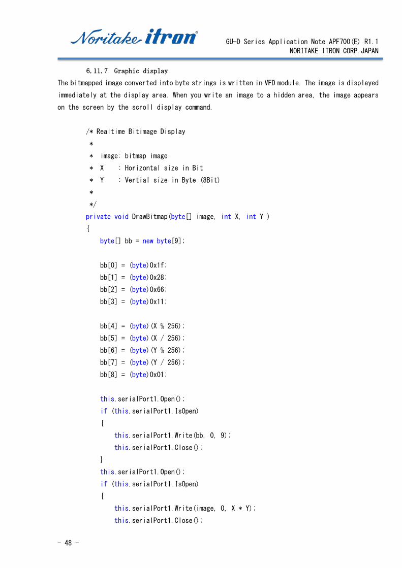
6.11.7 Graphic display
The bitmapped image converted into byte strings is written in VFD module. The image is displayed
immediately at the display area. When you write an image to a hidden area, the image appears
on the screen by the scroll display command.
/* Realtime Bitimage Display
*
* image: bitmap image
* X : Horizontal size in Bit
* Y : Vertial size in Byte (8Bit)
*
*/
private void DrawBitmap(byte[] image, int X, int Y )
{
byte[] bb = new byte[9];
bb[0] = (byte)0x1f;
bb[1] = (byte)0x28;
bb[2] = (byte)0x66;
bb[3] = (byte)0x11;
bb[4] = (byte)(X % 256);
bb[5] = (byte)(X / 256);
bb[6] = (byte)(Y % 256);
bb[7] = (byte)(Y / 256);
bb[8] = (byte)0x01;
this.serialPort1.Open();
if (this.serialPort1.IsOpen)
{
this.serialPort1.Write(bb, 0, 9);
this.serialPort1.Close();
}
this.serialPort1.Open();
if (this.serialPort1.IsOpen)
{
this.serialPort1.Write(image, 0, X * Y);
this.serialPort1.Close();

GU-D Series Application Note APF700(E) R1.1
NORITAKE ITRON CORP.JAPAN
- 49 -
}
}
6.11.8 Graphic display example
The following is a sample program that opens the graphic file and calls “DrawBitmap()”. This
program is added “Button3” and run as a click event. Please note that you cannot display which
is larger than display are size. Moreover, when the vertical resolution of the bitmap image
is not a multiple of 8, its remainder part is not displayed.
private void button3_Click(object sender, EventArgs e)
{
int i, j;
byte b2;
OpenFileDialog openDia = new OpenFileDialog();
if (openDia.ShowDialog() == System.Windows.Forms.DialogResult.OK)
{
Bitmap bmp = new Bitmap(openDia.FileName);
// @Show Bitmap on window
pictureBox1.Image = bmp;
// Transform Bitmap file into byte array
Byte[] bb = new Byte[bmp.Width * (bmp.Height/8)];
for (i = 0; i < bmp.Width; i++)
{
for (j = 0; j < (bmp.Height / 8); j++)
{
b2 = 0;
if (bmp.GetPixel(i, j * 8).G < 128) { b2 = 1; } b2 += b2;
if (bmp.GetPixel(i, j * 8 + 1).G < 128) { b2++; } b2 += b2;
if (bmp.GetPixel(i, j * 8 + 2).G < 128) { b2++; } b2 += b2;
if (bmp.GetPixel(i, j * 8 + 3).G < 128) { b2++; } b2 += b2;
if (bmp.GetPixel(i, j * 8 + 4).G < 128) { b2++; } b2 += b2;
if (bmp.GetPixel(i, j * 8 + 5).G < 128) { b2++; } b2 += b2;
if (bmp.GetPixel(i, j * 8 + 6).G < 128) { b2++; } b2 += b2;
GU-D Series Application Note APF700(E) R1.1
NORITAKE ITRON CORP.JAPAN
- 50 -
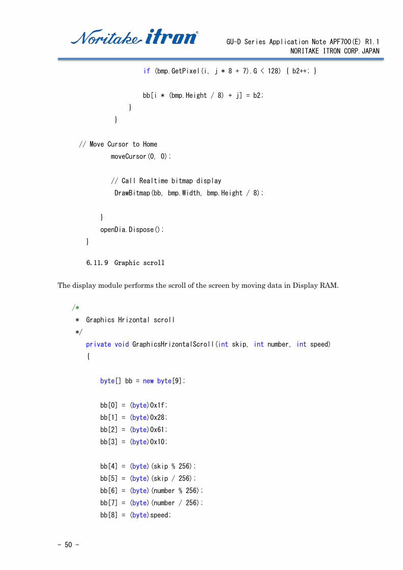
if (bmp.GetPixel(i, j * 8 + 7).G < 128) { b2++; }
bb[i * (bmp.Height / 8) + j] = b2;
}
}
// Move Cursor to Home
moveCursor(0, 0);
// Call Realtime bitmap display
DrawBitmap(bb, bmp.Width, bmp.Height / 8);
}
openDia.Dispose();
}
6.11.9 Graphic scroll
The display module performs the scroll of the screen by moving data in Display RAM.
/*
* Graphics Hrizontal scroll
*/
private void GraphicsHrizontalScroll(int skip, int number, int speed)
{
byte[] bb = new byte[9];
bb[0] = (byte)0x1f;
bb[1] = (byte)0x28;
bb[2] = (byte)0x61;
bb[3] = (byte)0x10;
bb[4] = (byte)(skip % 256);
bb[5] = (byte)(skip / 256);
bb[6] = (byte)(number % 256);
bb[7] = (byte)(number / 256);
bb[8] = (byte)speed;
GU-D Series Application Note APF700(E) R1.1
NORITAKE ITRON CORP.JAPAN
- 51 -
this.serialPort1.Open();
if (this.serialPort1.IsOpen)
{
this.serialPort1.Write(bb, 0, 9);
this.serialPort1.Close();
}
}
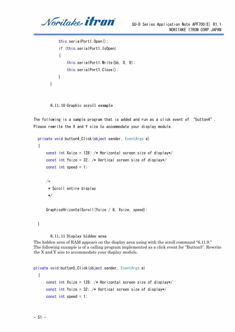
6.11.10 Graphic scroll example
The following is a sample program that is added and run as a click event of “button4”.
Please rewrite the X and Y size to accommodate your display module.
private void button4_Click(object sender, EventArgs e)
{
const int Xsize = 128; /* Horizontal screen size of display*/
const int Ysize = 32; /* Vertical screen size of display*/
const int speed = 1;
/*
* Scroll entire display
*/
GraphicsHrizontalScroll(Ysize / 8, Xsize, speed);
}
6.11.11 Display hidden area
The hidden area of RAM appears on the display area using with the scroll command "6.11.9." The following example is of a calling program implemented as a click event for “Button5”. Rewrite the X and Y size to accommodate your display module. private void button5_Click(object sender, EventArgs e)
{
const int Xsize = 128; /* Horizontal screen size of display*/
const int Ysize = 32; /* Vertical screen size of display*/
const int speed = 1;

GU-D Series Application Note APF700(E) R1.1
NORITAKE ITRON CORP.JAPAN
- 52 -
/*
* Show hidden area
*/
GraphicsHrizontalScroll(Ysize/8 * Xsize, 1, speed);
}
6.11.12 Character scroll Character scrolling is performed when the character is written. The horizontal scrolling is performed under the following conditions:
Condition 1: After setting the horizontal scroll mode, Condition 2: when the cursor reaches the right side of the screen, Condition 3: This display will initiate a scroll action by one character at next character
writing.
The scroll speed also needs to be set.
/*
* Horizontal Scroll Mode
*/
private void HorizontalScrollMD3()
{
byte[] bb = new byte[2];
bb[0] = (byte)0x1f;
bb[1] = (byte)0x03;
this.serialPort1.Open();
if (this.serialPort1.IsOpen)
{
this.serialPort1.Write(bb, 0, 2);
this.serialPort1.Close();
}
}
/*
* Horizontal Scroll Speed

GU-D Series Application Note APF700(E) R1.1
NORITAKE ITRON CORP.JAPAN
- 53 -
*/
private void HorizontalScrollSpeed(int speed)
{
byte[] bb = new byte[3];
bb[0] = (byte)0x1f;
bb[1] = (byte)0x73;
bb[2] = (byte)(speed % 32);
this.serialPort1.Open();
if (this.serialPort1.IsOpen)
{
this.serialPort1.Write(bb, 0, 3);
this.serialPort1.Close();
}
}
6.11.13 Character scroll example Example illustrates a use of this command. It is a function as a click event of “button6”.
private void button6_Click(object sender, EventArgs e)
{
const int speed = 2;
HorizontalScrollMD3();
HorizontalScrollSpeed(speed);
this.serialPort1.Open();
if (this.serialPort1.IsOpen)
{
this.serialPort1.Write("Horizontal Scroll Mode Test...........................");
this.serialPort1.Close();
}
}
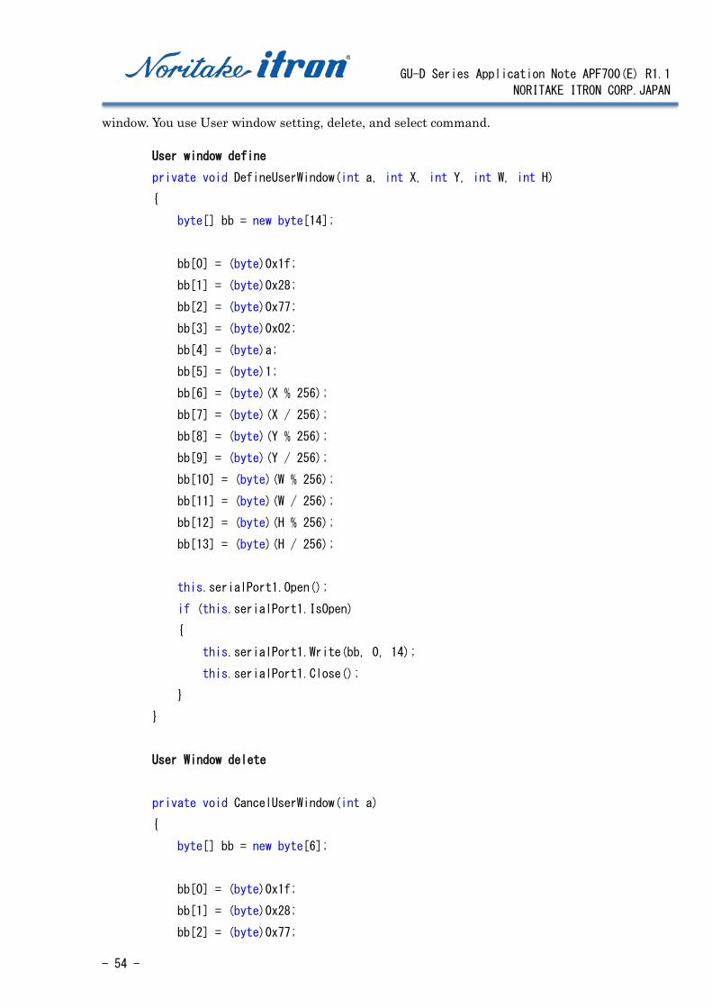
6.11.14 Subdivision of a screen in the user window. A user window can be separated into four sections and commands are performed within the user
GU-D Series Application Note APF700(E) R1.1
NORITAKE ITRON CORP.JAPAN
- 54 -
window. You use User window setting, delete, and select command.
User window define
private void DefineUserWindow(int a, int X, int Y, int W, int H)
{
byte[] bb = new byte[14];
bb[0] = (byte)0x1f;
bb[1] = (byte)0x28;
bb[2] = (byte)0x77;
bb[3] = (byte)0x02;
bb[4] = (byte)a;
bb[5] = (byte)1;
bb[6] = (byte)(X % 256);
bb[7] = (byte)(X / 256);
bb[8] = (byte)(Y % 256);
bb[9] = (byte)(Y / 256);
bb[10] = (byte)(W % 256);
bb[11] = (byte)(W / 256);
bb[12] = (byte)(H % 256);
bb[13] = (byte)(H / 256);
this.serialPort1.Open();
if (this.serialPort1.IsOpen)
{
this.serialPort1.Write(bb, 0, 14);
this.serialPort1.Close();
}
}
User Window delete
private void CancelUserWindow(int a)
{
byte[] bb = new byte[6];
bb[0] = (byte)0x1f;
bb[1] = (byte)0x28;
bb[2] = (byte)0x77;

GU-D Series Application Note APF700(E) R1.1
NORITAKE ITRON CORP.JAPAN
- 55 -
bb[3] = (byte)0x02;
bb[4] = (byte)a;
bb[5] = (byte)0;
this.serialPort1.Open();
if (this.serialPort1.IsOpen)
{
this.serialPort1.Write(bb, 0, 6);
this.serialPort1.Close();
}
}
User window select
private void SelectCurrentUserWindow(int a)
{
byte[] bb = new byte[5];
bb[0] = (byte)0x1f;
bb[1] = (byte)0x28;
bb[2] = (byte)0x77;
bb[3] = (byte)0x01;
bb[4] = (byte)a;
this.serialPort1.Open();
if (this.serialPort1.IsOpen)
{
this.serialPort1.Write(bb, 0, 5);
this.serialPort1.Close();
}
}
6.11.15 User window example
The following is a sample program that assign to a click event of “Button9”.
A 50x16 pixels user window is set to the upper left corner of the screen, and it is displayed
there as "Window". When character scrolling and a graphic display are performed without a break,
its data is written in this user window.
---------------------------------------
private void button7_Click(object sender, EventArgs e)
{
GU-D Series Application Note APF700(E) R1.1
NORITAKE ITRON CORP.JAPAN
- 56 -
const int UserWindow1 = 1;
DefineUserWindow(UserWindow1, 0, 0, 50, 2);
SelectCurrentUserWindow(UserWindow1);
this.serialPort1.Open();
if (this.serialPort1.IsOpen)
{
this.serialPort1.Write("Window");
this.serialPort1.Close();
}
}
----------------------------------------
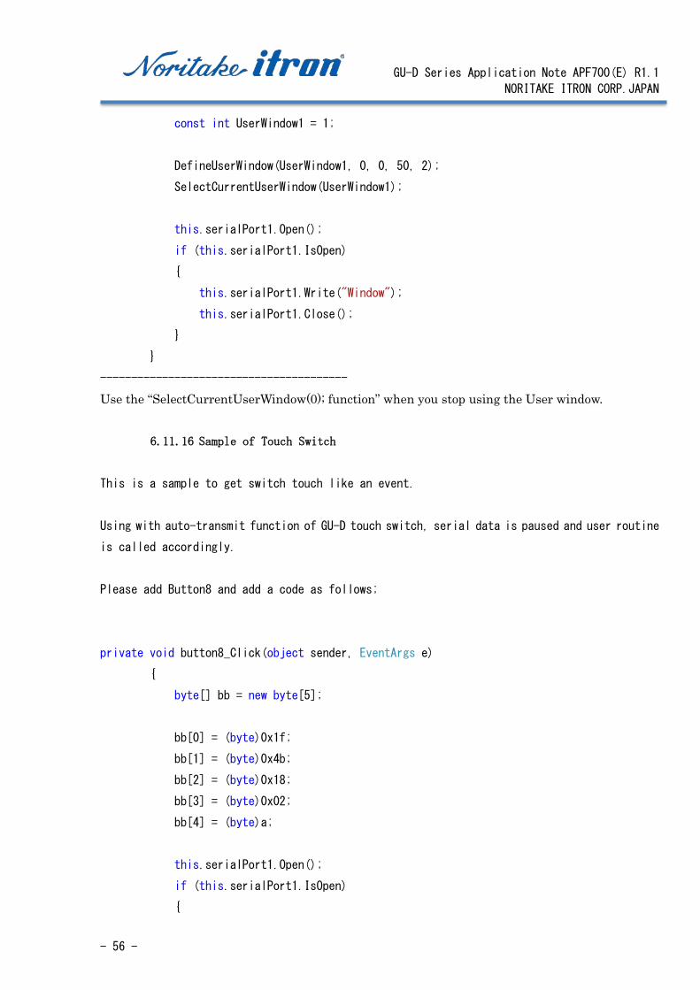
Use the “SelectCurrentUserWindow(0); function” when you stop using the User window.
6.11.16 Sample of Touch Switch
This is a sample to get switch touch like an event.
Using with auto-transmit function of GU-D touch switch, serial data is paused and user routine
is called accordingly.
Please add Button8 and add a code as follows;
private void button8_Click(object sender, EventArgs e)
{
byte[] bb = new byte[5];
bb[0] = (byte)0x1f;
bb[1] = (byte)0x4b;
bb[2] = (byte)0x18;
bb[3] = (byte)0x02;
bb[4] = (byte)a;
this.serialPort1.Open();
if (this.serialPort1.IsOpen)
{

GU-D Series Application Note APF700(E) R1.1
NORITAKE ITRON CORP.JAPAN
- 57 -
this.serialPort1.Write(bb, 0, 5);
// this.serialPort1.Close();
}
At property of serialPort1, click an event icon,
then double click "DataReceived" event.
In code edit window, enter following code.
Then add code to be executed at touch as
switchTouch() function.
void switchTouched(int sw, int onoff)
{
serialPort1.Write("\r\nTouchSwitch:");
if (sw < 10) { serialPort1.Write(" ");}
serialPort1.Write(sw.ToString());
if(onoff == 0)
{
serialPort1.Write(" OFF");
}else
{
serialPort1.Write(" ON!");
}
}
private void serialPort1_DataReceived(object sender,
System.IO.Ports.SerialDataReceivedEventArgs e)
{
int rd;
int sw;
int onoff;
rd = serialPort1.ReadByte();
if(rd == 0x11)
{

GU-D Series Application Note APF700(E) R1.1
NORITAKE ITRON CORP.JAPAN
- 58 -
sw = serialPort1.ReadByte();
onoff = serialPort1.ReadByte();
switchTouched(sw, onoff);
}
}
And add a button9 to terminate touch switch reaction.
private void button9_Click(object sender, EventArgs e)
{
byte[] bb = new byte[4];
bb[0] = (byte)0x1f;
bb[1] = (byte)0x4b;
bb[2] = (byte)0x18;
bb[3] = (byte)0x00;
// this.serialPort1.Open();
if (this.serialPort1.IsOpen)
{
this.serialPort1.Write(bb, 0, 4);
this.serialPort1.Close();
}
}
GU-D Series Application Note APF700(E) R1.1
NORITAKE ITRON CORP.JAPAN
- 59 -
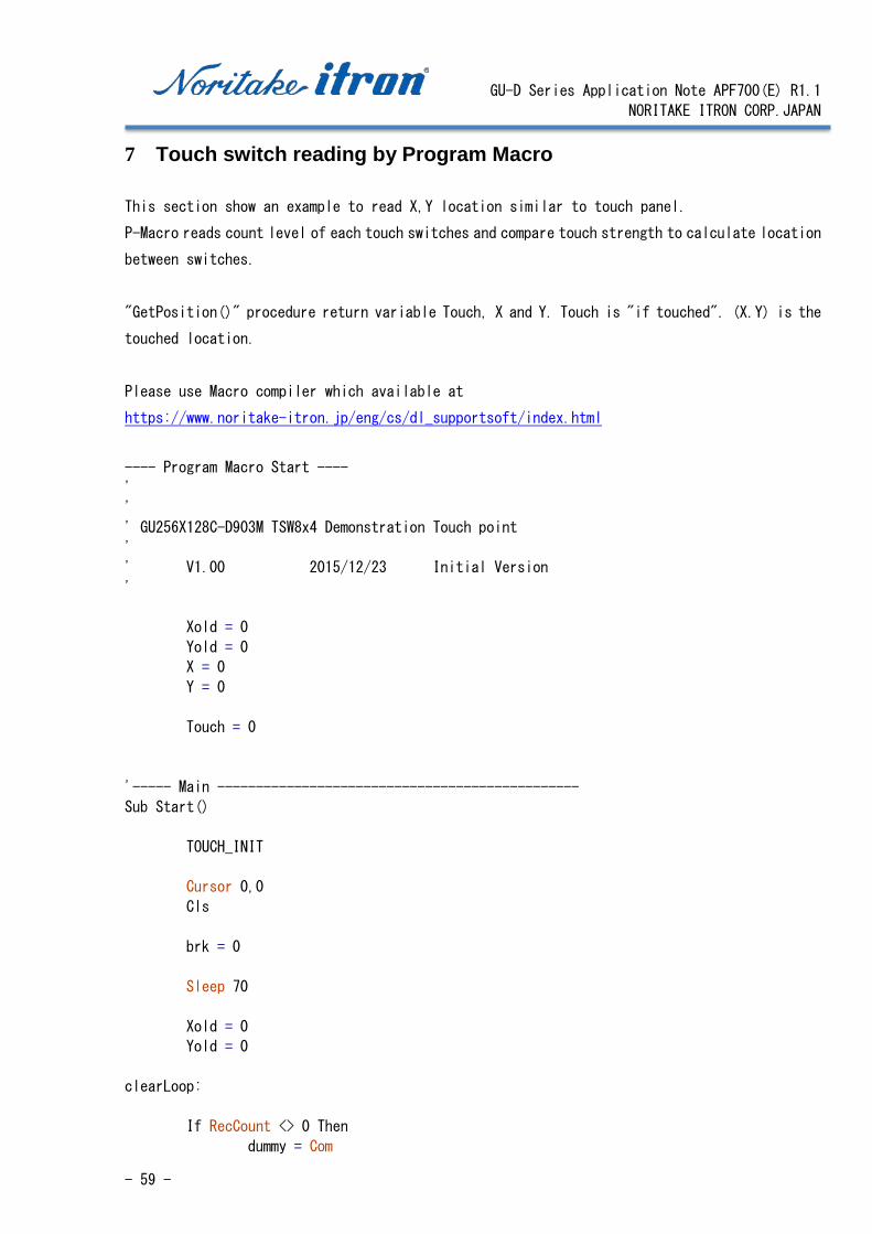
7 Touch switch reading by Program Macro
This section show an example to read X,Y location similar to touch panel.
P-Macro reads count level of each touch switches and compare touch strength to calculate location
between switches.
"GetPosition()" procedure return variable Touch, X and Y. Touch is "if touched". (X.Y) is the
touched location.
Please use Macro compiler which available at
https://www.noritake-itron.jp/eng/cs/dl_supportsoft/index.html
---- Program Macro Start ----
'
'
' GU256X128C-D903M TSW8x4 Demonstration Touch point
'
' V1.00 2015/12/23 Initial Version
'
Xold = 0
Yold = 0
X = 0
Y = 0
Touch = 0
'----- Main -----------------------------------------------
Sub Start()
TOUCH_INIT
Cursor 0,0
Cls
brk = 0
Sleep 70
Xold = 0
Yold = 0
clearLoop:
If RecCount <> 0 Then
dummy = Com
GU-D Series Application Note APF700(E) R1.1
NORITAKE ITRON CORP.JAPAN
- 60 -
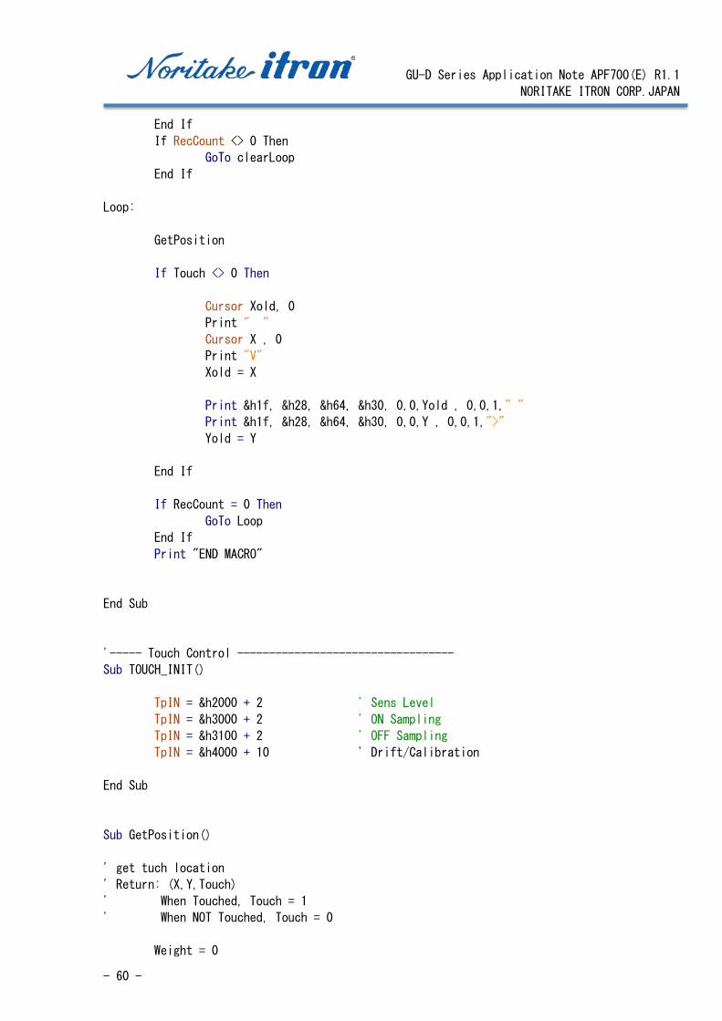
End If
If RecCount <> 0 Then
GoTo clearLoop
End If
Loop:
GetPosition
If Touch <> 0 Then
Cursor Xold, 0
Print " "
Cursor X , 0
Print "V"
Xold = X
Print &h1f, &h28, &h64, &h30, 0,0,Yold , 0,0,1," "
Print &h1f, &h28, &h64, &h30, 0,0,Y , 0,0,1,">"
Yold = Y
End If
If RecCount = 0 Then
GoTo Loop
End If
Print "END MACRO"
End Sub
'----- Touch Control ----------------------------------
Sub TOUCH_INIT()
TpIN = &h2000 + 2 ' Sens Level
TpIN = &h3000 + 2 ' ON Sampling
TpIN = &h3100 + 2 ' OFF Sampling
TpIN = &h4000 + 10 ' Drift/Calibration
End Sub
Sub GetPosition()
' get tuch location
' Return: (X,Y,Touch)
' When Touched, Touch = 1
' When NOT Touched, Touch = 0
Weight = 0
GU-D Series Application Note APF700(E) R1.1
NORITAKE ITRON CORP.JAPAN
- 61 -
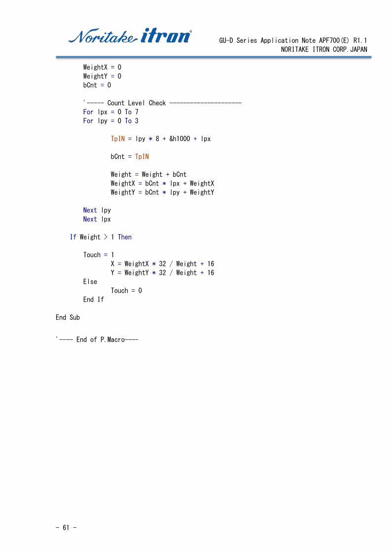
WeightX = 0
WeightY = 0
bCnt = 0
'----- Count Level Check ---------------------
For lpx = 0 To 7
For lpy = 0 To 3
TpIN = lpy * 8 + &h1000 + lpx
bCnt = TpIN
Weight = Weight + bCnt
WeightX = bCnt * lpx + WeightX
WeightY = bCnt * lpy + WeightY
Next lpy
Next lpx
If Weight > 1 Then
Touch = 1
X = WeightX * 32 / Weight + 16
Y = WeightY * 32 / Weight + 16
Else
Touch = 0
End If
End Sub
'---- End of P.Macro----
GU-D Series Application Note APF700(E) R1.1
NORITAKE ITRON CORP.JAPAN
- 62 -
8 Trouble Shooting 8.1 BUSY
GU-D series is required to use hardware handshake to prevent missing character(s). For
Asynchronous serial and SPI, MBUSY (Module Busy) signal is prepared.
For I2C interface, the handshake can be performed by either/both of "clock stretch" or/and MBUSY.
Especially scroll and wait command which may take very long time, hardware handshake is important
to achieve efficient programing.
8.2 Reset The display controller cannot accept data or commands during the internal power up
initialization. During this initialization, BUSY output is set to "BUSY", then do not write
data or commands during this period.
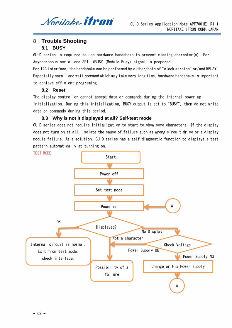
8.3 Why is not it displayed at all? Self-test mode GU-D series does not require initialization to start to show some characters. If the display
does not turn on at all, isolate the cause of failure such as wrong circuit drive or a display
module failure. As a solution, GU-D series has a self-diagnostic function to displays a test
pattern automatically at turning on.
TEST MODE
Possibility of a
failure
No Display
Power Supply NG
Power Supply OK
OK
Not a character
Start
Power off
Set test mode
Displayed?
Check Voltage
Power on
Internal circuit is normal.
Exit from test mode,
check interface.
Change or Fix Power supply
A
A

GU-D Series Application Note APF700(E) R1.1
NORITAKE ITRON CORP.JAPAN
- 63 -
8.4 How to set "TEST MODE" When "TEST" jumper is shorted at power up, GU-D series enters into self-test mode, and indicate
some message automatically without command or data from Host controller.
Self-test is useful to judge if cause of no display is by controller or display itself.
When "5V power is properly applied" and "Reset isn't low", no display on self-test-mode indicate
probable failure of display itself.
8.4.17 Location of TEST jumper
GU128X32D-D903S
GU140X32F-D903S
GU256X64C-D903M
GU256X128C-D903M
GU-D Series Application Note APF700(E) R1.1
NORITAKE ITRON CORP.JAPAN
- 64 -
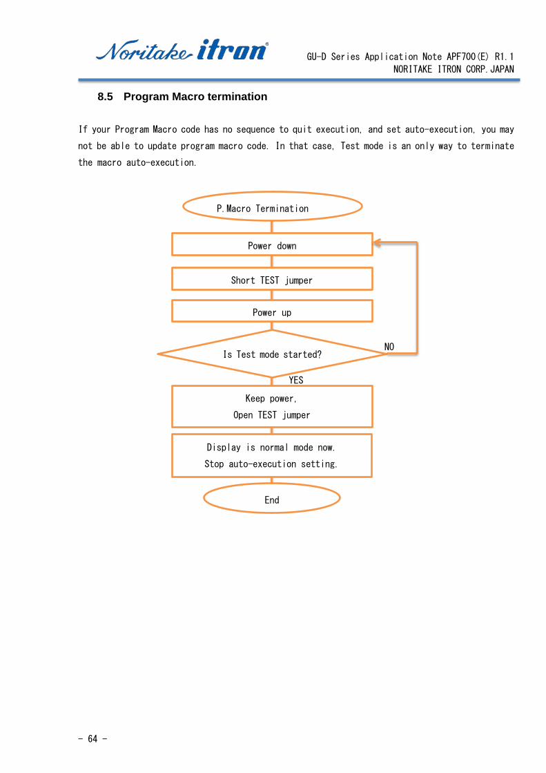
8.5 Program Macro termination
If your Program Macro code has no sequence to quit execution, and set auto-execution, you may
not be able to update program macro code. In that case, Test mode is an only way to terminate
the macro auto-execution.
P.Macro Termination
Power down
Short TEST jumper
Power up
Is Test mode started?
Keep power,
Open TEST jumper
Display is normal mode now.
Stop auto-execution setting.
End
YES
NO

GU-D Series Application Note APF700(E) R1.1
NORITAKE ITRON CORP.JAPAN
- 65 -
9 Support TOOL We can offer support tool for you, please contact from our website.
Homepage (Japanese): http://www.noritake-itron.jp/ (English): http://www.noritake-itron.jp/eng/ (Chinese): http://www.noritake-itron.jp/chinese/
9.1 GUD-10K
Platform: Windows PC
・ GUD10K is tutorial Software that offers guidance in creating, programming, sequencing
and displaying messages with the Noritake GU-D Series.
・ This tool offers a list of command sequences to perform complex operations with the
display screen.
9.2 Macro Compiler
This is an Editor/Compiler for Program macro code. Used language is similar to Basic Language,
and VFD control instructions are supported.
9.3 GU TOOL BOX
This may convenient to working with GU-D series display.
Feature:
Validate connection between PC and GU-D
Test and experience basic display functions
Observe initialize internal settings
Initialize Flash memory, memory switch etc.
Capture GU-D screen

GU-D Series Application Note APF700(E) R1.1
NORITAKE ITRON CORP.JAPAN
- 66 -
10 Environment We are committed to the understanding of environmentally hazardous substances established by
the Green Procurement Guideline.
We have also certification of ISO14000 and are keeping striving for the correspondence to an
environmental issue.
10.1 RoHS Compliance All standard module products including GU-D series are compatible with the RoHS Directive.
GU-D series is exempt from lead-containing component RoHS as follows:
・ Lead oxide in glass used in Vacuum Fluorescent display.
・ Lead oxide contained in the ceramic and glass in electronic components.
Ceramic capacitors do not contain lead.
・ Lead in high melting point solder components used to connect the internal semiconductor
11 Safety standard Printed circuit board materials are certified UL :94-V0 flame retardant grade.
The UL certification number is indicated on the printed circuit board.
12 Disclaimers and limitations The contents provided in this document are carefully created and managed by our company, but
we cannot guarantee to use these contents on all platforms. If you have any problems or questions,
please consult us.
Noritake sample codes are only for the use of Noritake products. Please carry out operating
verification for final products such as application software on your responsibility.
Support tools provided in a form of the installer may contain programs that are used under license.
These must not be reproduced, modified, or integrated, etc. as reverse engineered, reverse
compiled, or reverse assembled.
13 Contact us If you have any questions or requests, please consult our sales office or customer
support desk ([email protected]).
End of Document