Vacuum Design - 1
15
75 7. Vacuum System 7.1 Introduction Beam lifetime and beam stability are of major importance to any synchrotron; the interaction of the stored particles with the residual gas molecules leads to particles losses caused by scattering processes. Because of this a detailed design of the vacuum system is essential. Thus, the vacuum system design, requirements and the calculations for SESAME will be discussed and summarized here. In general the design will be based on ANKA, SLS and CLS vacuum system designs. 7.2 SESAME Parameters General characteristics of the machine are tabulated in Table (7.1) [1]: Table 7.1: SESAME main parameters Beam Energy (GeV) 2 Beam Current (mA) 400 Horizontal Emittance (nm) 16.960 Number of Straights 16 of which: 8 Wigglers 1 Injection 2 RF Cavities 5 Undulators Circumference (m) 120.0 Dipole Bending radius (m) 4.942 Dipole magnet length (m) 1.941 Dipole Magnetic Field (T) 1.350 These Parameters are the most important from vacuum point of view, others like photon flux, photodesorption yield, average pressure…etc will be calculated later on. 7.3 Requirements Basic requirements common to most storage ring UHV systems are: • Beam lifetime more than 10 hours • Smooth chamber to minimize electromagnetic fields induced by the beam • Sufficient cooling, to dissipate the heat load associated with synchrotron radiation • Good and sufficient monitoring; achieving the pressure is as much important as evaluating that pressure correctly • Separation of the sectors by pneumatic valves • Reasonable cost • Flexible system for improvements and upgrading • Reliable system 7.4 Materials for Vacuum Chamber 7.4.1 General In general, synchrotron light source vacuum chambers are fabricated from stainless steel, aluminium or copper. However copper is used internally for photon stop or radiation absorbers, where high heat loads have to be dissipated. Titanium, Beryllium, ceramics and Nickel alloys have also been used for special purposes.
-
Upload
sansur20004987 -
Category
Documents
-
view
219 -
download
0
Transcript of Vacuum Design - 1

8/3/2019 Vacuum Design - 1
http://slidepdf.com/reader/full/vacuum-design-1 1/15
75
7. Vacuum System
7.1 Introduction
Beam lifetime and beam stability are of major importance to any synchrotron; the interaction
of the stored particles with the residual gas molecules leads to particles losses caused by scattering
processes. Because of this a detailed design of the vacuum system is essential. Thus, the vacuum
system design, requirements and the calculations for SESAME will be discussed and summarized
here. In general the design will be based on ANKA, SLS and CLS vacuum system designs.
7.2 SESAME Parameters
General characteristics of the machine are tabulated in Table (7.1) [1]:
Table 7.1: SESAME main parameters
Beam Energy (GeV) 2
Beam Current (mA) 400
Horizontal Emittance (nm) 16.960
Number of Straights 16 of which: 8 Wigglers
1 Injection
2 RF Cavities5 Undulators
Circumference (m) 120.0
Dipole Bending radius (m) 4.942
Dipole magnet length (m) 1.941
Dipole Magnetic Field (T) 1.350
These Parameters are the most important from vacuum point of view, others like photon flux,
photodesorption yield, average pressure…etc will be calculated later on.
7.3 Requirements
Basic requirements common to most storage ring UHV systems are:
• Beam lifetime more than 10 hours
• Smooth chamber to minimize electromagnetic fields induced by the beam
• Sufficient cooling, to dissipate the heat load associated with synchrotron radiation
• Good and sufficient monitoring; achieving the pressure is as much important as
evaluating that pressure correctly
• Separation of the sectors by pneumatic valves
• Reasonable cost
• Flexible system for improvements and upgrading
• Reliable system
7.4 Materials for Vacuum Chamber 7.4.1 General
In general, synchrotron light source vacuum chambers are fabricated from stainless steel,
aluminium or copper. However copper is used internally for photon stop or radiation absorbers,
where high heat loads have to be dissipated. Titanium, Beryllium, ceramics and Nickel alloys have
also been used for special purposes.

8/3/2019 Vacuum Design - 1
http://slidepdf.com/reader/full/vacuum-design-1 2/15
76
Many factors need to be taken into account to select the suitable material to be used in the
vacuum system; vacuum performance, mechanical strength (stability, hardness), thermal
conductivity, magnetic permeability, surface resistivity, materials vapour pressure, how easy the
material is for fabrication, joining and cleaning.
Concerning vacuum performance; the main vacuum property to be discussed is the photon
desorption yield and its reduction with beam dose, see Figure (7.1) [2].
(a) Stainless Steel (b) Aluminium (c) Copper
Figure 7.1: Photon stimulation desorption yield reduction with accumulated beam dose for (a) stainless
steel, (b) aluminium and (c) copper
One can notice that almost all behave similarly, however copper and aluminium show higherphotodesorption initially than stainless steel. It has been shown by experiments that a surface which
has been vented after being ‘scrubbed’ by the beam will not give yields as high as a surface which
has not been ‘scrubbed’, however, aluminium is the worst in comparison to stainless steel and
copper.
Aluminium has good properties such as: it is easy for manufacturing by extrusion especially
for long beam tubes and complex chambers, also it has good thermal conductivity and it is
completely non magnetic. However aluminium has several disadvantages such as it has weak
mechanical properties, higher desorption yield and it is difficult for joining.
Copper (OFHC copper) is used for UHV applications; it has good thermal conductivity but it
has higher desorption yield compared to stainless steel. Also its production process is more
complicated and expensive in comparison to aluminium (if copper is used for vacuum vessels withan antechamber, the chambers need to be extruded separately from the antechamber and welded
together afterwards) [3].
Stainless steel (316LN alloy) is usually used for UHV applications. It has good mechanical
strength, is easy to weld, has high hardness and low outgassing rates. It also has a low magnetic
permeability so it can be used within magnets. The thermal conductivity of stainless steel is very
poor in comparison to copper, therefore to transport high heat loads (e.g. in absorbers) copper plates
need to be used. Also the value of electrical conductivity is very low (low eddy currents, resistive
wall effect) [4] for the stainless steel.
Stainless steel can be baked out up to (350°C) to remove water and fired (up to 900°C) to
reduce H2.
Stainless steel seems to be a suitable material for SESAME vacuum chambers because of its
properties, however OFHC copper should be used for the absorbers.
There are two more arguments for choosing stainless steel as the material for the vacuum
chamber:
• One should use a material, which can be handled by the accelerator laboratory and there
exist expertise to deal with them.

8/3/2019 Vacuum Design - 1
http://slidepdf.com/reader/full/vacuum-design-1 3/15
77
• The vacuum system should be build by the industry. Within the industry most experiences
are available with stainless steel.
All these arguments are in favor of stainless steel as the suitable material for the vacuum chamber.
7.4.2 Vacuum Chamber Design
The design of the vacuum chamber is not an easy task; many factors must be taken into
consideration to have the right size of the vacuum chamber; Touschek scattering, gas scattering,
closed-orbit errors, injection requirements and momentum acceptance. Taking these into account
will give the beam stay clear which therefore will give the minimum required aperture. The actualmachine aperture may lie out of this because of RF or engineering requirements.
There mainly are two principles for the vacuum chamber design: 1) a straight with full
antechamber design (3rd
generation synchrotron light sources like SLS and CLS) 2) a vacuum
chamber in which the antechamber is only in the bending and the first following focusing magnet
and a single chamber vacuum vessel with a distributed photon absorber in the rest of the ring (2nd
generation synchrotron light sources like ANKA).
Slit opening height between the vacuum chamber and the antechamber in the dipole must be
decided carefully to prevent the high local thermal stress, which can be achieved by increasing the
height of the slit or water-cooled copper shield along the vacuum chamber between the
antechamber
The introduction of the electrode of the BPM into the vacuum system can be done by one of
the following ways:
a) Welding it directly to the BPM blocks
b) Using a separate flange to hold the electrodes, which is connected to the BPM blocks
The BPM must be bolted rigidly to the magnet girders. To get rid of misreading of the BPM
two options are available:
1) The BPM electrode can be connected to bellows to allow movement of the vacuum
chambers.
2) The movements of the vacuum chamber are detected by optical sensors and can be
compensated for when reading the BPM [4], [5].
In order to avoid the extra cost of having a separate flange for the BPM one solution is toweld the BPM electrode directly to the BPM blocks and bolt it to the girders and connect it to the
bellows to get rid of the misreading.
Manufacturing should be done in such a way to eliminate trapped volumes (e.g. due to poor
welding) to get better vacuum performance since these volumes will increase the pump down time
due to virtual leaks appearing [6].
All components need to be cleaned properly. Cleaning procedures must guarantee that all
components will be suitable for UHV. Cleaning will reduce the evolution of the gases from the
surfaces, the source of these gases can be oils, greases, fluxes, fingerprints…etc. Cleaning should be
suitable for the material type and should not leave any deposits behind [6].
7.5 Calculations
Basic calculations for any vacuum system design need to be carried out in such a way to
achieve important values for the system; such as photon flux, pressure profile, power
dissipation…etc.
The pressure profile may be used for the optimization of the vacuum system. The profile
gives the best location for the pumps and type of pumps (lumped or distributed) needed to be
installed. The pressure profile can also give an indication of the location of the absorbers and the
required number to get the lowest average dynamic pressure.

8/3/2019 Vacuum Design - 1
http://slidepdf.com/reader/full/vacuum-design-1 4/15
78
The storage ring will be divided into 8 cells and each cell will contain one straight and two
dipole bending magnets; see Figure (7.2) and the discussion in section 5.1. Figure (7.2) shows the
unit cell with the pumps distributed along the chamber. This layout, which has been used for the
evaluation of the pressure profile, is simply based on the space available between the magnets to put
in the pumping ports. A further decision has to be made on the location of the pumping ports shown
in Figure (7.2). One possibility is to put the pumping ports underneath the vacuum chamber; this
will allow the designer to have a wider pumping port without limiting the available space, therefore,
decreasing the conductance limitation of the system.
Figure 7.2: SESAME cell (1/8 of the storage Ring) and basic layout for the pumps distribution
Calculations have been carried out for unbaked stainless steel vacuum chamber for CO (mass
28) at 293K. The vacuum and antechamber dimensions and profiles are described in sections 5.3,
5.4 and 5.5. The dipole vacuum chamber design is based on the one used for ANKA.
Evaluation of the pressure profile along the storage ring can be done in several ways; one
possible method is the Monte-Carlo simulation, which gives accurate results but exact dimensions
of the vacuum chamber should already be known. Since at this stage of the project there are no
detailed drawings of the vacuum chamber, it is not possible to use the Monte-Carlo simulation.
Instead, the pressure profile will be calculated analytically.
The calculations will be performed based on the gas dynamic balance equation inside a
vacuum chamber [7], as shown in Equation (7.1):
2
2
dL
nd ucnq
dt
dnV +−= (7.1)
Where: V is vacuum chamber volume,
n is the gas density,
q the gas desorption flux from both thermal desorption and photo stimulated desorption
q = η t F + η γ Γ (7.2)
Where: F is surface area,
Γ is the photon flux,
η t , η γ are the thermal and photo stimulation desorption yields,
L is the longitudinal axis of the vacuum chamber.
A detailed discussion along with the solution of this equation is presented in reference [7].
Detailed calculations1
for SESAME (under the previous conditions of the design) have been
carried out using the Mathcad program, however this report will include only the results achieved
for SESAME.
7.5.1 Photon Flux from the DipolesThe radiation from the dipoles will find its way into 3 possible places: 1) to the crotch
absorber 2) to the beam line front ends 3) It irradiates the walls of the vacuum chamber.
Equation (7.3) shows that the total photon flux for SESAME with a beam energy (E) of 2GeV
and a beam current (I) of 400mA is 6.43x10²⁰
photons/s.
1- Calculations have been carried out with the help of ASTeC Vacuum Science Group/ Daresbury Laboratories.
8/3/2019 Vacuum Design - 1
http://slidepdf.com/reader/full/vacuum-design-1 5/15
79
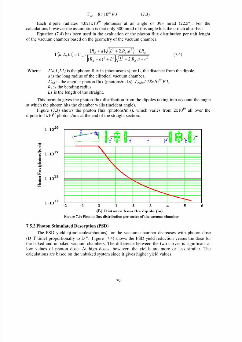
I E tot .108 20×=Γ (7.3)
Each dipole radiates 4.021x10¹⁹
photons/s at an angle of 393 mrad (22.5°). For the
calculations however the assumption is that only 300 mrad of this angle hits the crotch absorber.
Equation (7.4) has been used in the evaluation of the photon flux distribution per unit lenght
of the vacuum chamber based on the geometry of the vacuum chamber.
( )( ) ( )
[ ]2222
22
..2.)(
..2..1,,
aa R L La R
LRa R La R L La
d d
d d d
rad
++++
−++Γ =Γ (7.4)
Where: Γ (a,L,L1) is the photon flux in (photons/m.s) for L, the distance from the dipole,
a is the long radius of the elliptical vacuum chamber,
Γ rad is the angular photon flux (photons/rad.s), Γ rad=1.28x10²⁰
.E.I ,
Rd is the bending radius,
L1 is the length of the straight.
This formula gives the photon flux distribution from the dipoles taking into account the angle
at which the photon hits the chamber walls (incident angle).
Figure (7.3) shows the photon flux (photons/m.s), which varies from 2x10¹⁹
all over the
dipole to 1x10¹⁷
photons/m.s at the end of the straight section.
Figure 7.3: Photon flux distribution per meter of the vacuum chamber
7.5.2 Photon Stimulated Desorption (PSD)
The PSD yield η(molecules/photons) for the vacuum chamber decreases with photon dose
(D=Γ.time) proportionally to D
-α
. Figure (7.4) shows the PSD yield reduction versus the dose forthe baked and unbaked vacuum chambers. The difference between the two curves is significant at
low values of photon dose. At high doses, however, the yields are more or less similar. The
calculations are based on the unbaked system since it gives higher yield values.

8/3/2019 Vacuum Design - 1
http://slidepdf.com/reader/full/vacuum-design-1 6/15
80
Figure 7.4: PSD yield for CO for unbaked and baked vacuum chambers
Figure 7.5: Photodesorption yield for the straight section per unit length as a
function of the beam dose
The curve has been divided into 3 ranges according to the slope of the curve. Equation (7.4)
shows the ranges for each slope which have been used for the calculations.

8/3/2019 Vacuum Design - 1
http://slidepdf.com/reader/full/vacuum-design-1 7/15
81
×
⟨⟨
Ι≤
=
− (III) otherwise )D
10(102
(II) 10D10 )D
100.004(
)(10D 0.004
0.6520
3
20190.319
19
(7.5)
7.5.3 Photodesorption Along the Straight
The desorption flux (molecules/s) can be simply achieved by multiplying the yield by the
photon flux. Since the photon flux depends on the distance from the dipole, the values of the
photodesorption yield and flux will also vary with distance from the dipole. Figures (7.5) and (7.6)
show the desorption yield and the flux as a function of distance from the dipole for different beam
doses.
Figure 7.6: Desorption flux for the straight section per unit length and as a function of
the beam dose
7.5.4 Thermal Desorption
The thermal desorption have been calculated taking the following parts into consideration:
vacuum chamber, antechamber, the front ends (assuming the front ends length is 2.5m) and the
pumping ports (assuming the pumping ports are 0.5m long), the thermal outgassing rate of 10-11
mbar.lt/(sec.cm2).
7.5.5 Pressure Profile
For the evaluation of the pressure profile, the vacuum chamber has been divided into parts;
each defined upon its function (pumping part or not…) and location. This arrangement allows
definition of the parts and the distribution be changed more easily. Table (7.2) shows one of the
databases for the vacuum chamber of SESAME with one absorber (200 mm width) and pumps
along the chamber with 250 mm pumping ports (pumping port for the dipole pump is of 300 mm

8/3/2019 Vacuum Design - 1
http://slidepdf.com/reader/full/vacuum-design-1 8/15
82
width). l is the length of the part, L is the accumulated length from the beginning of the achromat,
xap and yap are the dimensions of the vacuum chamber.
Table 7.2: The vacuum chamber divided into sections for the calculation purposes
For this data and with 500l/s effective absorber pumping speed (assuming an efficiency of
50% at 10-9
mbar) and 150l/s nominal pumping speed for the pumps along the achromat (assume
100l/s effective pumping speed), an average pressure of 1.233x10⁻⁹
mbar has been achieved.
Figure (7.7) shows the base pressure profile (due to thermal desorption / without SR beam)
and the dynamic pressure (due to both the thermal and the photo stimulated desorption / with SR
beam).
ACHROMAT VACUUM CHAMBER ELEMENTS
l
(mm)
L
(mm)X (m) Y (m) Pumping Photons
Antechamber
(m)Element
250 250 0.035 0.015 Lumped pump Distributed flux 0Achromat end
pump
640 890 0.035 0.015 No pump Distributed flux 0 VC
250 1140 0.035 0.015 Lumped pump Distributed flux 0 Pump
570 1710 0.035 0.015 No pump Distributed flux 0 VC
500 2210 0.035 0.015 No pump Photons in the Dipole VC. 0.08094 Dipole VC
300 2510 0.035 0.015 Lumped pump Photons in the Dipole VC. 0.11181 Pump
891 3401 0.035 0.015 No pump Photons in the Dipole VC. 0.22059 Dipole VC
250 3651 0.035 0.015Lumped pump +
absorberPhotons in the Dipole VC. 0.39540
Absorber +
Pump
350 4001 0.035 0.015 No pump Distributed flux 0 VC
250 4251 0.035 0.015 Lumped pump Distributed flux 0 Pump
640 4891 0.035 0.015 No pump Distributed flux 0 VC
250 5141 0.035 0.015 Lumped pump Distributed flux 0 Pump
1084 6225 0.035 0.015 No pump Distributed flux 0 VC
250 6475 0.035 0.015 Lumped pump Distributed flux 0 Pump
1084 7559 0.035 0.015 No pump Distributed flux 0 VC
250 7809 0.035 0.015 Lumped pump Distributed flux 0 Pump
640 8449 0.035 0.015 No pump Distributed flux 0 VC
250 8699 0.035 0.015 Lumped pump Distributed flux 0 Pump
350 9049 0.035 0.015 No pump Distributed flux 0 VC
500 9549 0.035 0.015 No pump Photons in the Dipole VC. 0.08094 Dipole VC
300 9849 0.035 0.015 Lumped pump Photons in the Dipole VC. 0.11181 Pump
891 10740 0.035 0.015 No pump Photons in the Dipole VC. 0.22059 VC
250 10990 0.035 0.015Lumped pump +
absorberPhotons in the Dipole VC. 0.39540
Absorber +
Pump
570 11560 0.035 0.015 No pump Distributed flux 0 VC
250 11810 0.035 0.015 Lumped pump Distributed flux 0 Pump
640 12450 0.035 0.015 No pump Distributed flux 0 VC250 12700 0.035 0.015 Lumped pump Distributed flux 0 Pump
1025 13725 0.035 0.015 No pump Distributed flux 0 VC
250 13975 0.035 0.015 Lumped pump Distributed flux 0 Pump
1025 15000 0.035 0.015 No pump Distributed flux 0 VC
250 15250 0.035 0.015 Lumped pump Distributed flux 0 Pump

8/3/2019 Vacuum Design - 1
http://slidepdf.com/reader/full/vacuum-design-1 9/15
83
Figure 7.7: Pressure profile for one cell of the vacuum chamber (1/8 of the
storage ring), Pav,T = 9.35x10⁻¹⁰
mbar, Pav,PSD = 2.97x10⁻¹⁰
mbar, Pav
= 1.233x10⁻⁹ mbar
This is the profile that will be achieved from the design proposed in this stage of the project.
The following changes however could give lower values for the average pressure:
1) Increasing the pumping speed for the pumps close to the absorber to a value of 1000 l/s
will reduce the pressure to a value of 1.164x10⁻⁹
mbar.
2) Increasing the pumping speed for the pumps along the vacuum chamber from 150 l/s to
200 l/s (about 150 l/s effective pumping speed) will decrease the average pressure to
9.66x10⁻¹⁰ mbar.
3) Changing the design to have two absorbers with 200 mm width and 750 l/s pumping
speed, and pumps along the unit cell with 150 mm width and 150 l/s pumping speed
results an average dynamic pressure of 9.43x10⁻¹⁰
mbar as shown in Figure (7.8).

8/3/2019 Vacuum Design - 1
http://slidepdf.com/reader/full/vacuum-design-1 10/15
84
Figure 7.8: The pressure profile for SESAME cell with two absorbers of 200mm
width and 750l/s pumping speed, pumps along the achromat with150mm width and 150l/s pumping speed, Pav = 9.43x10
-10mbar
4) Increasing the pumping speed for the pump near the absorber to 1000 l/s for the case (3) will
decrease the average pressure down to 8.79x10⁻¹⁰
mbar.
5) Adding a third absorber to the case (3) in the straight section and before the third sextupole will
increase the average pressure to 1.107x10⁻⁹
mbar, because it will increase the base pressure due
to the area increase (the antechamber). Figure (7.9) shows the pressure profile for this case.
Figure 7.9: The pressure profile for the SESAME cell with 3 absorbers (200 mm
and 750 l/s) and pumps along the cell (150 mm and 150 l/s)

8/3/2019 Vacuum Design - 1
http://slidepdf.com/reader/full/vacuum-design-1 11/15
85
The increasing of the pumping speed may decrease the dynamic pressure of the system
however. Due to the conductance limitation, the improvements would reach to a point that further
increase would decrease the pressure slightly. Figure (7.10) shows the average pressure variation
with the absorber pumps pumping speed of 100 l/s and 150 l/s for the pumps distributed along the
chamber. Figure (7.11) shows the average pressure variation with different pumping speeds (1000
l/s, 750 l/s and 500 l/s) for the absorber pumps distributed along the chamber.
Figure 7.10: Average pressure variation with the absorber pumps pumping speed of 100 l/s
and 150 l/s and with the pumps distributed along the chamber
Figure 7.11: Average pressure variation with different pumping speeds, the absorber pumps are
distributed along the chamber
Figures (7.10) and (7.11) are for a system with two absorbers (200mm width) and pumps
along the vacuum chamber with 100mm width. The figures could be used to optimize the pumping
speed required for such a system. With absorbers effective pumping speed selected to be 500l/s,
pumps distributed along the vacuum chamber would be preferred to have pumping speed of 100-
200 l/s, because below 100 l/s the pressure value is not satisfactory, and over 200 the value of the
pressure has only small variations due to conductance limitation.
8/3/2019 Vacuum Design - 1
http://slidepdf.com/reader/full/vacuum-design-1 12/15
86
A proposal for the pumps pumping speed for SESAME could be made to have for the
absorbers an effective pumping speed of 750 l/s and for the pumps distributed along the storage ring
an effective pumping speed not less than 100 l/s.
Increasing the pumping speed may help getting better vacuum but some improvements in the
design may also give the same results; in general, increasing the area of port’s aperture (the width
and the gap) will increase the transmission probability (and so increasing the effective pumping
speed of the pumps), also opening out the spouts (wider profile up to the pump) will increase the
effective pumping speed (e.g. by a factor of two for nominal pumping speed of 500 l/s). Installation
of the pumping port underneath the vacuum chamber with short pumping port may also help having
better effective pumping speed.It is important to mention that in the estimated pressure profiles, synchrotron from the dipoles
was only considered and further calculations need to be done to consider the synchrotron radiation
from the insertion devices. Also it is worth mentioning that the calculated pressure values are just
estimations of the pressure values in the chamber, and the real values might be a little different. So
in order to be on the safe side, it is better to have an arrangement of the pumps that gives the lowest
value for the pressure.
7.6 Lumped or Distributed Pumping?
The decision of having lumped or distributed pumps along the vacuum chamber depends on
many factors; gas load, pressure profile, vacuum chamber profile, conditioning time, in-situ bake
out, engineering requirements, space available, cost…etc.In general for a gas molecule to be removed by the vacuum system, it has to find its way into
the pump and be trapped. Thus the rate at which gas can be removed from the system (i.e. the
pumping speed) is determined by the product of the arrival rate of the gas molecules at the pump
and the capture coefficient of the pump for such molecules.
If the capture coefficient is close to 1, then the only way to decrease the pressure is by
increasing the arrival rate.
For a lumped pump, the area of the pump entrance aperture and the transmission of the
molecules determine the arrival rate through the pump throat to the pump body.
For a distributed pump, only the area presented by the pump to the molecules determines the
arrival rate.
Lumped pumps are cheaper compared to the distributed pumps since they are of standard
ranges available in the market, while the distributed pumps are designed on request, which makes
them more expensive. The installation and maintenance of the lumped pumps could be easier
compared to the distributed pumps, because the installation and maintenance of the distributed
pumps may require removal of the major vacuum vessels. It should also be noted that the lumped
pumps could be separated easily from the system by using valves, which is not possible with the
distributed pumps.
Since the pressure profiles show clearly that lumped pumping of the system is sufficient to
achieve a pressure of 1.23x10⁻⁹
mbar, without considering any improvements, lumped pumping is a
good proposal for the vacuum system. Once the synchrotron radiation of the insertion devices was
included in the calculations, if places with high gas load (high pressure) originate, then distributed
pumps could be used (just in case the lumped pumps close to these areas couldn’t solve the
problem).To increase the transmission probability of the system, a proposal for the lumped pumping
can be made by allowing the pumping spout to be short, wide and as close to the vacuum chamber
as possible; installation of the pumping port underneath the vacuum chamber will give all of these
[8].

8/3/2019 Vacuum Design - 1
http://slidepdf.com/reader/full/vacuum-design-1 13/15
87
7.7 Pumps Selection
7.7.1 Rough Pumping
Rough pumping is required so as to achieve pressure below 10-6
mbar so that the UHV pumps
can be started. The time required to achieve such pressure is important during the conditioning
stage. The volume of the system and the gas flow conductance are the main factors in the evaluation
of the pumping down of the system.
It would be a good decision to use turbo molecular pump because of its good performance
(turbo molecular pumps are clean if magnetic bearings have been used, and provide pressure down
to 10-6 mbar). Taking the high cost of the turbo molecular pumps into consideration, and also the
requirements for another rough pump to reach high vacuum so that the turbo pump can operate, it is
better to have a station for the one quarter of the ring, if the calculations gave a short pumping time
for single station for two cells of the ring.
Scroll pumps are good candidates to be used with the turbo molecular pump to achieve
pressure 10-2
mbar; they are cheap, light and clean [9].
7.7.2 UHV Pumps
In General, Ion pumps and gutter pumps are used in the storage rings.
The ion pumps could be of several types: the Diode ion pump, the Noble Diode ion pump,
and the Triode ion pump.
The diode ion pump has a pumping speed twice higher than that of the triode pump at 10-9 mbar for all reactive gases; CO, CO2, H2. The pumping speed for noble gases is approximately 5%
less than that of the quoted pumping speed for N2. Also the further pumping liberates the previously
buried noble gas molecules and results in unstable pumping behavior ‘instability of the noble
gases’. Using Triode pumps reduces the instability of the noble gases, and the pumping speed for
the noble gases increases by 15% approximately. The Noble Diode pump utilizes a Tantalum
cathode in place of the Titanium cathode of the Diode pump, which increases pumping speed and
stability for noble gases.
The NEG and titanium sublimation pumps have a considerable pumping speed for hydrogen
and all reactive gases, but do not pump noble gases and hydrocarbons. Also the pumping material
requires periodic regeneration to maintain pumping performance, by heating to 400°C
approximately.Diode Ion pump is a good proposal and is sufficient to pump down the storage ring to the
required pressure. Using noble diode ion pump is effective in pumping the noble gases, and for high
pressure locations where a large pumping speed is required, NEG or TSP will solve the problem.
[10], [11]
7.8 Vacuum Instrumentation
The measurement of vacuum is as much important as providing the required vacuum. The
total and partial pressure must be correctly measured. Locations of the gauge heads throughout the
facility need to be determined, and the specifications and the types of gauges must be studied
carefully.
7.8.1 Total Pressure Gauges
It is necessary to measure total pressures down to UHV (i.e. < 10-9
mbar) throughout the
vacuum system and the gauge system is needed to do this. The storage ring and the beam port front
ends require reliable readings of total pressure at 1x10⁻¹⁰
mbar. The injector pressure measurement
system requires a reliable reading down to 1x10⁻⁹
mbar.
Unfortunately, it is not possible to cover the whole pressure range with a single gauge; a first
gauge is required to cover low and medium vacuum (from atm. to 10-3
mbar) and that will also be
8/3/2019 Vacuum Design - 1
http://slidepdf.com/reader/full/vacuum-design-1 14/15
88
useful to provide reading during pumping down the system and during vacuum failure. A second
gauge is required for UHV readings as well.
For low and medium vacuum ranges, since the reading is just required to give an indication of
the situation, there is no need to use a very accurate gauge, so a gauge such as Pirani gauge is a
good choice, and it covers the range from atm. to 10-3
mbar.
For the UHV range, two types of gauges are in common use on the accelerators around the
world: cold cathode gauges and hot cathode gauges.
The hot cathode gauge needs a third gauge to cover readings between 10-3
and 5x10⁻⁴
mbar.
Also penning discharge cold cathode gauge does not cover values below 10-9
mbar, while inverted
magnetron discharge cold cathode gauge covers pressure ranges from 10 -3 down to 10-11 mbar. Forthe injector, penning gauge could be used as long as pressure is below 10
-9mbar.
Each part of the accelerator must be covered by a pressure gauge. In general, each vacuum
section (area between two gate valves) should contain one pair of total pressure gauges, and may
require another gauge in case of failure of the first pair. Also the RF cavity, injection straight
section, injector vacuum system, rough pump set, all should have at least one pair of total pressure
gauges.
Interlock provision needs to be provided to switch on/off the ion pumps, rough pumps, valves,
operation of other gauges and RGAs [12].
7.8.2 Partial Pressure Gauges:
It is important for UHV applications to know the composition of the residual gases within thesystem. Quadrupole mass spectrometer used as Residual Gas Analyzer (RGA) measures the partial
pressure of the gases in the system.
The RGA should give full coverage for the vacuum sections and close to the crotch absorbers.
So it is required to locate them close to the down stream of the dipole magnets. At least one RGA is
needed for each part of the accelerator; the injector vacuum system, the injection straight section,
the RF cavity and the ID straight section.
Control units of all the gauges and the other vacuum equipments need to be provided with all
necessary cables, interlocks, front panels… etc, and they should have the ability to influence the
main control system.
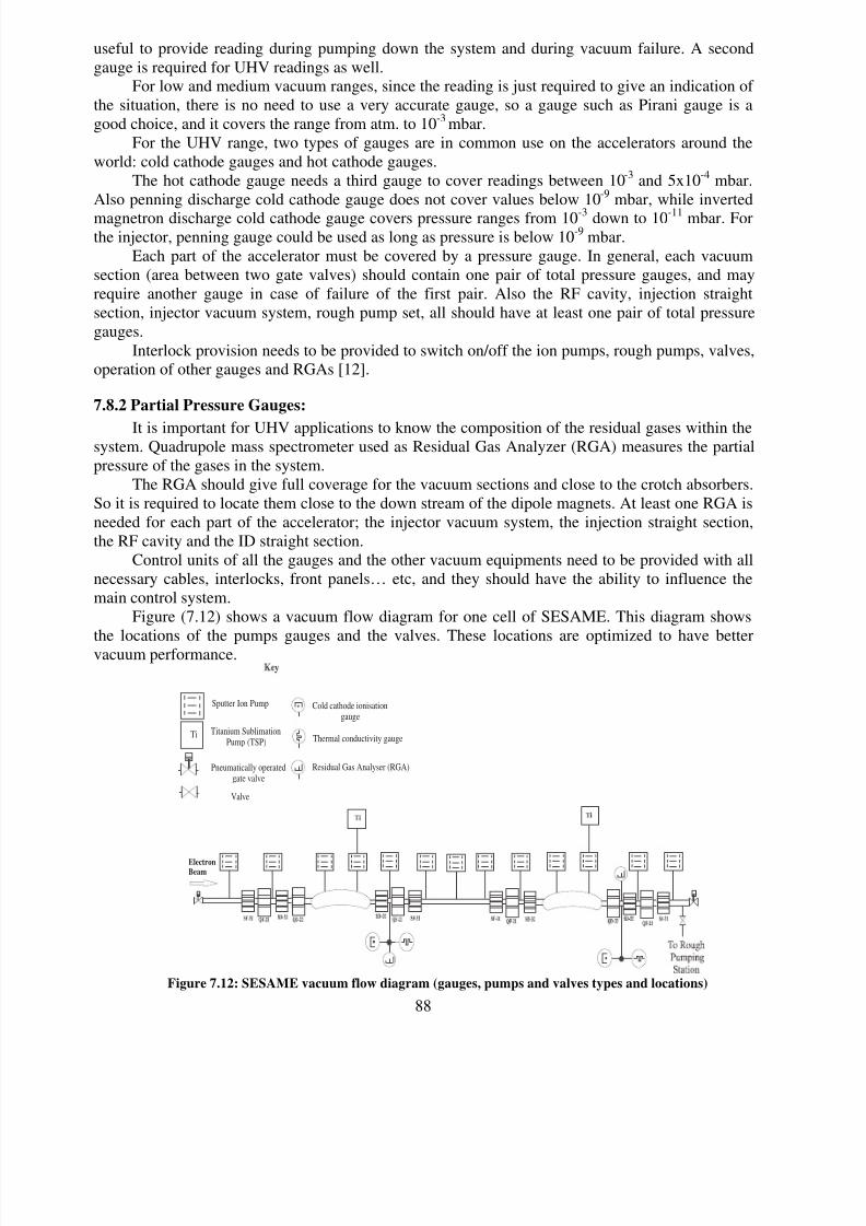
Figure (7.12) shows a vacuum flow diagram for one cell of SESAME. This diagram shows
the locations of the pumps gauges and the valves. These locations are optimized to have better
vacuum performance.
Electron
Beam
Sputter Ion Pump
Pneumatically operatedgate valve
Cold cathode ionisationgauge
Thermal conductivity gauge
Residual Gas Analyser (RGA)
Valve
Ti Titanium SublimationPump (TSP)
Figure 7.12: SESAME vacuum flow diagram (gauges, pumps and valves types and locations)

8/3/2019 Vacuum Design - 1
http://slidepdf.com/reader/full/vacuum-design-1 15/15
89
7.9 In-sit Bake Out
The in-situ bake out is mainly required in the early stages of a vacuum cycle, see Figure (7.4).
After beam scrubbing of 100A.h the results for in-situ bake out and not an in-situ bake out are just
the same for the lifetime of the beam. Also the thickness of the heater and the insulation leads to
larger magnets which directly affect the cost of the magnets. Also there are the cost of the in-situ
bake out system (heaters and insulation...) and other accelerator components.
Sufficient cleaning procedure and vacuum firing (900°C) under vacuum (10-5
Torr) and pre
bake out of the vacuum chamber improve the life time by decreasing the thermal desorption and
therefore the base pressure.
So for this stage of the machine design it is proposed not to have an in-situ bake out.
References:
[1] D. Einfeld, SESAME, “First Draft of the Conceptional Design, version 8”, March 2002.
[2] Ron Ried, “ Materials choice for Diamond Vacuum System”, (Internal Report) Oct. 2000.
[3] Erhard Huttel, “ Materials for Accelerator Vacuum System”.
[4] Lother Schulz, “Stainless Steel Vacuum Chambers” Oct. 2001.
[5] Shulz et al. Vacuum System for the Swiss Light Source”
[6] D. Lowe, “CLS Storage Ring Vacuum Chambers”, March 2001.
[7] Oleg Malyshev et al. “Calculated Pressure profile Along the Diamond Storage Ring Cell.”
(Internal Report) Jan 2002.
[8] Ron Reid, “ Lumped or Distributed Pumping?” (Vacuum Design Notes) Apr. 1996.[9] Keith Middleman et al. “ Rough Pumping Systems for Diamond Storage Ring, Part 1 and Part
2”, (Internal Report) Oct. 2001.
[10] E. Huttel, “The Vacuum System for the Synchrotron Radiation Source ANKA” [11] Tom Weston, “Capture pumps”, Vacuum Design Notes, Feb. 1996.
[12] Joe Herbert, “Vacuum Instrumentation for Diamond ”, (Internal Report) Jan 2002.