Steam turbines subject to flexible operation · VGB DIGITAL VGB PowerTech 11 l
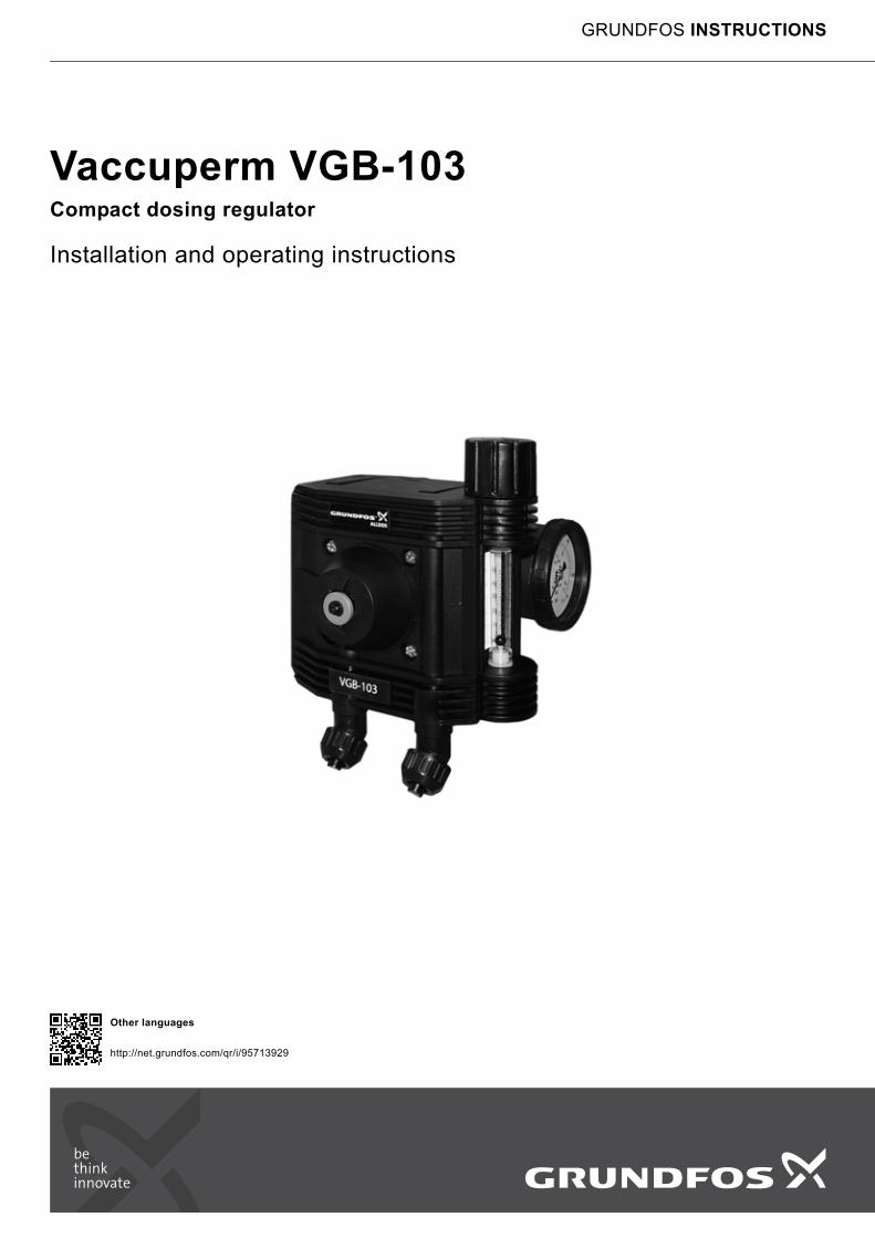
Vaccuperm VGB-103Compact dosing regulator
Installation and operating instructions
GRUNDFOS INSTRUCTIONS
Other languages
http://net.grundfos.com/qr/i/95713929
En
glis
h (G
B)
English (GB) Installation and operating instructions
Original installation and operating instructions
CONTENTSPage
1. Safety instructionsThese installation and operating instructions contain important information for the user of the product:
• Technical data
• Instructions for commissioning and use
• Safety instructions
If you require further information, or if problems occur that are not described in detail in this manual, please contact Grundfos.
1.1 Symbols used in this document
This manual contains the following standardised safety instructions about possible residual risks:
1.2 Safety advice for handling chlorine
1.2.1 Hazards of chlorine gas
• Causes whooping cough, dyspnoea and lacrimation.
• Has a slight paralysing effect to the central nervous system.
• Concentrations of more than 10 ppm chlorine gas in the respiratory air mean an acute danger to life.
• Inhaling air with a high concentration of chlorine gas for a long time is lethal.
1.2.2 Hazards of liquid chlorine
• Causes burns of skin.
• Causes reddening and blistering of skin.
1.2.3 Rules of conduct
• Change chlorine containers only with gas mask.
• Enter contaminated rooms only with protective suit and compressed-air respirator.
• In case of flight wear gas mask, if possible. Observe wind direction.
1.3 Protective equipment
1.3.1 Personal protective equipment
The operating authority of a chlorine gas dosing system has to provide respiratory equipment (full-sight gas mask), personally fitted, labelled by name, with an effective chlorine filter (B2P3) and at least 1 spare filter per gas mask, for each operator. The protective equipment must be stored easily accessible outside the chlorine rooms.
• For systems with chlorine drums at least 2 protective suits with compressed-air respirators must be available.
1.3.2 Obligations of the operating authority
• Introducing the operators to handling the protective equipment.
• The operators must use the personal protective equipment regularly, or carry out exercises with it at least every 6 months.
• The gas mask filters must be replaced regularly
– after the expiry of the date of durability
– at least 6 months after opening (note the opening date on the filter)
– after contact with chlorine.
• Observe employing prohibition according to the local laws.
1.3.3 Storage of the protective equipment
• Outside the chlorine rooms
• Well visible
• Easily available at any time
• Protected from dust and moisture.
1. Safety instructions 21.1 Symbols used in this document 21.2 Safety advice for handling chlorine 21.3 Protective equipment 21.4 First aid in case of accidents 31.5 Handling chlorine containers 31.6 Chlorine rooms 4
2. Introduction 52.1 Correct usage 52.2 Inappropriate usage 52.3 Qualification of the users 52.4 Responsibilities of the operator 52.5 Maintenance and service personnel 52.6 Type key VGB-103 compact dosing unit 62.7 Transport and storage 62.8 Unpacking 6
3. Technical data 73.1 General technical data 73.2 Dosing flow 73.3 Connections 73.4 Accessories 73.5 Dimensions 83.6 Physical and chemical data of chlorine 9
4. Design and function 94.1 Description of the device 94.2 Functional principle 10
5. Assembly and installation 115.1 Selection of vacuum lines 115.2 Connecting the compact dosing unit 125.3 Installation example 12
6. Startup 126.1 Checking the tightness 136.2 Chlorine extraction 14
7. Operation 157.1 Switching on the chlorine gas dosing system 157.2 Setting the dosing flow 157.3 Reading the dosing flow 157.4 Changing the chlorine container while the system is
running 157.5 Switching off the chlorine gas dosing system 16
8. Maintenance 16
9. Fault finding 17
10. Disposal 17
Warning
Prior to installation, read these installation and operating instructions. Installation and operation must comply with local regulations and accepted codes of good practice.
Warning
If these safety instructions are not observed, it may result in personal injury.
Caution If these safety instructions are not observed, it may result in malfunction or damage to the equipment.
NoteNotes or instructions that make the job easier and ensure safe operation.
Warning
Toxic by inhalation.
Irritating to eyes, respiratory system and skin.
2
En
gli
sh
(G
B)
1.4 First aid in case of accidents
1.4.1 First aid after inhaling chlorine
1. Keep calm.
2. Remove injured persons from the dangerous area.
3. Helpers must pay attention to personal protection.
4. Remove contaminated clothes.
5. Calm down injured persons and keep them warm with blankets.
6. Supply fresh air, use oxygen respirator, if possible.
– No mouth-to-mouth resuscitation!
7. Call medical aid or transport to hospital
– lying
– sitting in case of difficulty in breathing.
– State chlorine as the cause.
1.4.2 First aid after chemical burn of the skin
1. Keep calm.
2. Remove contaminated clothes.
3. Rinse skin with plenty of water.
4. Bandage the wound aseptically.
5. Seek medical aid.
– State chlorine as the cause.
1.4.3 First aid after chemical burn of the eyes
1. Keep calm.
2. Rinse eyes with plenty of water while the patient is lying.
– Protect healthy eye, if necessary.
– Spread eyelids widely, let the eye move to all sides.
3. Seek ophthalmologist.
– State chlorine as the cause.
1.4.4 First aid after internal chemical burn
1. Keep calm.
2. Drink water in short sips.
– If possible, take medical charcoal.
3. Seek medical aid.
– State chlorine as the cause.
1.5 Handling chlorine containers
Chlorine is stored in grey steel cylinders or drums in lockable chlorine rooms. Due to safety precautions, chlorine containers are only filled up to 95 % of their capacity.
Kind of gas, weight, owner, producing date and date of the last testing have to be noted clearly on the container.
Observe the following:
• Store chlorine containers fireproof.
• Protect chlorine containers from heat and sunlight.
• Chlorine containers should not be modified or repaired by the user.
• Keep full and empty containers closed.
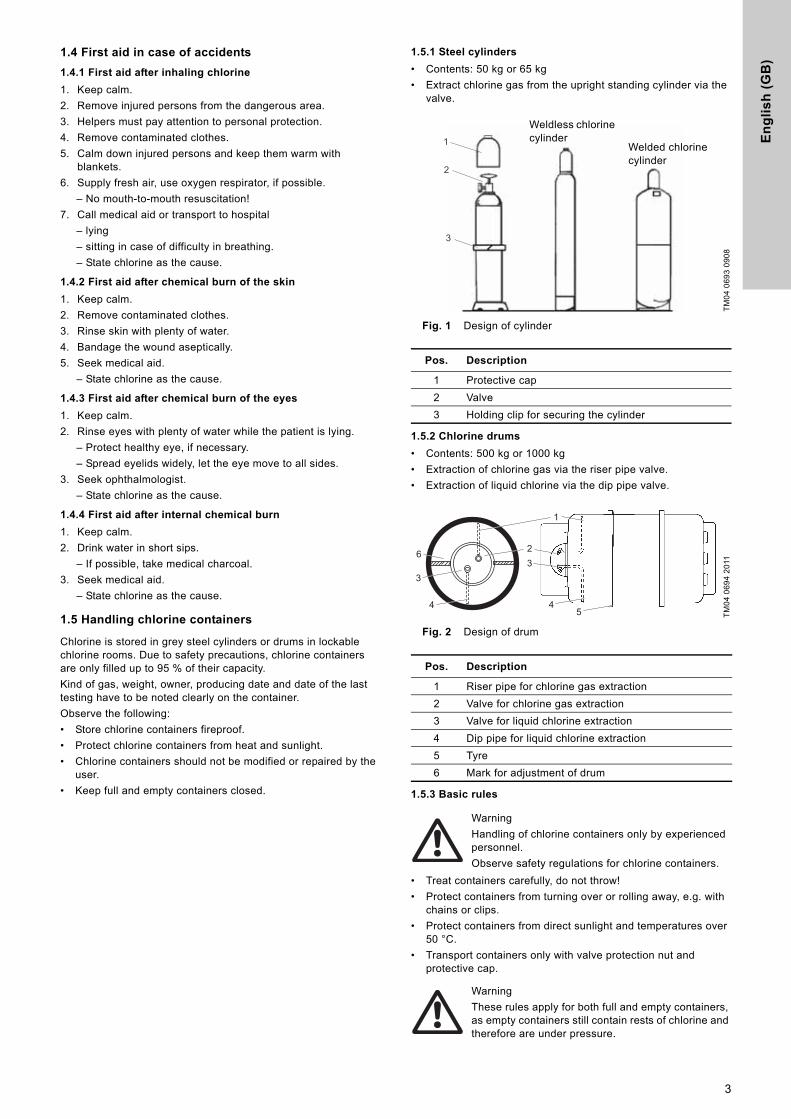
1.5.1 Steel cylinders
• Contents: 50 kg or 65 kg
• Extract chlorine gas from the upright standing cylinder via the valve.
Fig. 1 Design of cylinder
1.5.2 Chlorine drums
• Contents: 500 kg or 1000 kg
• Extraction of chlorine gas via the riser pipe valve.
• Extraction of liquid chlorine via the dip pipe valve.
Fig. 2 Design of drum
1.5.3 Basic rules
• Treat containers carefully, do not throw!
• Protect containers from turning over or rolling away, e.g. with chains or clips.
• Protect containers from direct sunlight and temperatures over 50 °C.
• Transport containers only with valve protection nut and protective cap.
TM
04
06
93
09
08
Pos. Description
1 Protective cap
2 Valve
3 Holding clip for securing the cylinder
TM
04
06
94
20
11
Pos. Description
1 Riser pipe for chlorine gas extraction
2 Valve for chlorine gas extraction
3 Valve for liquid chlorine extraction
4 Dip pipe for liquid chlorine extraction
5 Tyre
6 Mark for adjustment of drum
Warning
Handling of chlorine containers only by experienced personnel.
Observe safety regulations for chlorine containers.
Warning
These rules apply for both full and empty containers, as empty containers still contain rests of chlorine and therefore are under pressure.
1
2
3
Welded chlorine cylinder
Weldless chlorine cylinder
2
5
36
4
1
3
4
3
En
glis
h (G
B)
1.5.4 Valid regulations
In Germany, the following regulations apply:
• Regulations for accident prevention "Chlorination of water" with process instructions (GUV-V D5)
• Regulations concerning places of work (ArbStättV)
• Technical rules for pressurized gases (TRG 280, 310 and 330)
• Operation of baths (BGR 108)
• Chlorine gas dosing systems for water treatment (DIN 19606)
• Chlorine for water treatment (DIN 19607)
1.6 Chlorine rooms
Chlorine rooms are rooms, where a chlorine gas dosing system and/or chlorine containers are located. The chlorine in these rooms is under pressure.
1.6.1 Regulations for chlorine rooms
According to the German regulations for accident prevention "Chlorination of water", such rooms have to meet the following requirements:
• They should not have connections to other rooms, and must be separated gas-tight and fire-resistant.
• They must be at ground level, dry and air-conditioned. The recommended room temperature is 18-20 °C. It should be neither lower than 0 °C nor higher than 50 °C.
• Overpressure lines of dosing equipment must not end in the open air.
• Ventilation openings leading into the open air must be limited to 2 x 20 cm2.
• Appropriate exhaust devices with downstream absorption systems must be installed.
• Chlorine gas must not get into lower-lying rooms, shafts, pits, canals or aspirating holes of ventilation systems.
• Chlorine rooms must be equipped with a water sprinkling system to precipitate the escaping chlorine gas.
– The sprinkling system must have a run-off with air trap.
– Operation must be possible manually from outside the chlorine rooms.
• A chlorine gas warning system must be installed
– with optical and acoustical alarm device,
– with connection to the water sprinkling system,
– with a warning system that reactivates automatically after switch-off (e.g. for container exchange).
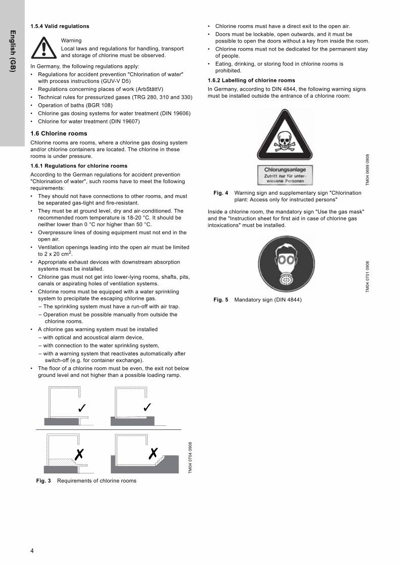
• The floor of a chlorine room must be even, the exit not below ground level and not higher than a possible loading ramp.
Fig. 3 Requirements of chlorine rooms
• Chlorine rooms must have a direct exit to the open air.
• Doors must be lockable, open outwards, and it must be possible to open the doors without a key from inside the room.
• Chlorine rooms must not be dedicated for the permanent stay of people.
• Eating, drinking, or storing food in chlorine rooms is prohibited.
1.6.2 Labelling of chlorine rooms
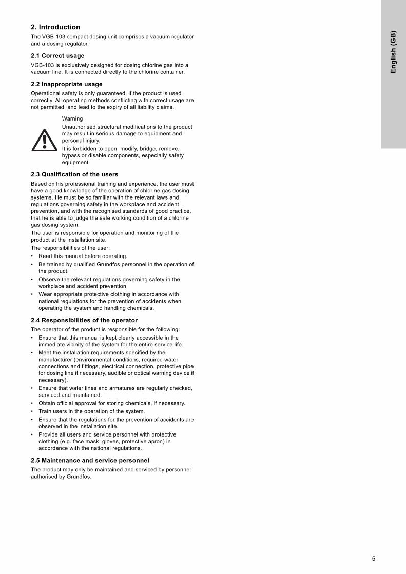
In Germany, according to DIN 4844, the following warning signs must be installed outside the entrance of a chlorine room:
Fig. 4 Warning sign and supplementary sign "Chlorination plant: Access only for instructed persons"
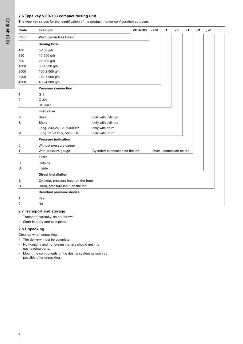
Inside a chlorine room, the mandatory sign "Use the gas mask" and the "Instruction sheet for first aid in case of chlorine gas intoxications" must be installed.
Fig. 5 Mandatory sign (DIN 4844)
Warning
Local laws and regulations for handling, transport and storage of chlorine must be observed.
TM
04
07
04
09
08
✓
✗ ✗
✓
TM
04
06
99
09
08
TM
04
07
01
09
08
4
En
gli
sh
(G
B)
2. IntroductionThe VGB-103 compact dosing unit comprises a vacuum regulator and a dosing regulator.
2.1 Correct usage
VGB-103 is exclusively designed for dosing chlorine gas into a vacuum line. It is connected directly to the chlorine container.
2.2 Inappropriate usage
Operational safety is only guaranteed, if the product is used correctly. All operating methods conflicting with correct usage are not permitted, and lead to the expiry of all liability claims.
2.3 Qualification of the users
Based on his professional training and experience, the user must have a good knowledge of the operation of chlorine gas dosing systems. He must be so familiar with the relevant laws and regulations governing safety in the workplace and accident prevention, and with the recognised standards of good practice, that he is able to judge the safe working condition of a chlorine gas dosing system.
The user is responsible for operation and monitoring of the product at the installation site.
The responsibilities of the user:
• Read this manual before operating.
• Be trained by qualified Grundfos personnel in the operation of the product.
• Observe the relevant regulations governing safety in the workplace and accident prevention.
• Wear appropriate protective clothing in accordance with national regulations for the prevention of accidents when operating the system and handling chemicals.
2.4 Responsibilities of the operator
The operator of the product is responsible for the following:
• Ensure that this manual is kept clearly accessible in the immediate vicinity of the system for the entire service life.
• Meet the installation requirements specified by the manufacturer (environmental conditions, required water connections and fittings, electrical connection, protective pipe for dosing line if necessary, audible or optical warning device if necessary).
• Ensure that water lines and armatures are regularly checked, serviced and maintained.
• Obtain official approval for storing chemicals, if necessary.
• Train users in the operation of the system.
• Ensure that the regulations for the prevention of accidents are observed in the installation site.
• Provide all users and service personnel with protective clothing (e.g. face mask, gloves, protective apron) in accordance with the national regulations.
2.5 Maintenance and service personnel
The product may only be maintained and serviced by personnel authorised by Grundfos.
Warning
Unauthorised structural modifications to the product may result in serious damage to equipment and personal injury.
It is forbidden to open, modify, bridge, remove, bypass or disable components, especially safety equipment.
5
En
glis
h (G
B)
2.6 Type key VGB-103 compact dosing unit
The type key serves for the identification of the product, not for configuration purposes.
2.7 Transport and storage
• Transport carefully, do not throw!
• Store in a dry and cool place.
2.8 Unpacking
Observe when unpacking:
• The delivery must be complete.
• No humidity and no foreign matters should get into gas-leading parts.
• Mount the components of the dosing system as soon as possible after unpacking.
Code Example VGB-103 -250 /1 -S -1 -O , -B 0
VGB Vaccuperm Gas Basic
Dosing flow
100 5-100 g/h
250 10-250 g/h
500 25-500 g/h
1000 50-1,000 g/h
2000 100-2,000 g/h
3000 150-3,000 g/h
4000 400-4,000 g/h
Pressure connection
1 G 1
2 G 3/4
3 US yoke
Inlet valve
B Basic only with cylinder
S Short only with cylinder
L Long, 230-240 V, 50/60 Hz only with drum
M Long, 110-115 V, 50/60 Hz only with drum
Pressure indication
0 Without pressure gauge
1 With pressure gauge Cylinder: connection on the left Drum: connection on top
Filter
O Outside
U Inside
Direct installation
B Cylinder, pressure input on the front
D Drum, pressure input on the left
Residual pressure device
1 Yes
0 No
6
En
gli
sh
(G
B)
3. Technical data3.1 General technical data
3.2 Dosing flow
3.3 Connections
3.4 Accessories
The following accessories are not included in the standard delivery:
• Hoses of different lengths
• Holding plate for wall fixing when changing containers
• Ammonia water for tightness check
• Liquid trap with long inlet valve
Accuracy ± 4 % of upper limit
Permissible medium
Cl2
Setting range 1:20
Empty signal Optical empty indication
FlowmeterAccording to the floater principle, ball in measuring glass, length of measuring glass 70 mm
Weight 1 kg
Pressure gauge0-10 bar, with/without limit contact for setting the minimum admission pressure
Short inlet valveSuitable for cylinder connection, without liquid trap (standard)
Long inlet valveSuitable for drum connection and liquid trap
5-100 g/h 0.2 - 5 lbs/day
10-250 g/h 0.5 - 14 lbs/day
25-500 g/h 1.5 - 26 lbs/day
50-1,000 g/h 2.5 - 50 lbs/day
100-2,000 g/h 5-100 lbs/day
150-3,000 g/h 10-150 lbs/day
400-4,000 g/h 30-220 lbs/day
Vacuum connection to the injector
for hose 8/11 mm
Pressure connection to the adsorption filter
for hose 8/11 mm
Pressure connection at the inlet valve
Union nut G 1
Union nut G 3/4
Closed yoke (US)
7
En
glis
h (G
B)
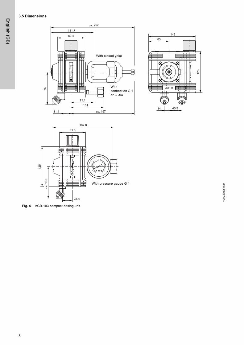
3.5 Dimensions
Fig. 6 VGB-103 compact dosing unit
TM
04
07
06
09
08
VGB-103
131.7
82.4
92
31.4 ca. 197
10171.1
14 40.3
126
14663
bar 160
Cl 2
0°C
ALL
DO
S2
187.8
81.8
125
ca.
100
31.4
ca. 257
With pressure gauge G 1
With closed yoke
With connection G 1 or G 3/4
8
En
gli
sh
(G
B)
3.6 Physical and chemical data of chlorine
Under normal conditions of pressure and temperature, chlorine is a yellowish green gas with a pungent odour, which exists as Cl2 molecule.
It is not flammable, but can promote the flammability of metals, hydrocarbons, etc.
Fig. 7 Vapour pressure curve of chlorine
Fig. 8 Solubility of chlorine gas in water
4. Design and function
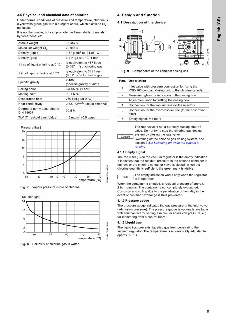
4.1 Description of the device
Fig. 9 Components of the compact dosing unit
4.1.1 Empty signal
The red mark (6) on the vacuum regulator is the empty indication. It indicates that the residual pressure in the chlorine container is too low, or the chlorine container valve is closed. When the chlorine quantity is sufficient, the green mark is visible.
When the container is emptied, a residual pressure of approx. 2 bar remains. The container is not completely evacuated. Corrosion and soiling due to the penetration of humidity in the event of container exchange is thus prevented.
4.1.2 Pressure gauge
The pressure gauge indicates the gas pressure at the inlet valve (admission pressure). The pressure gauge is optionally available with limit contact for setting a minimum admission pressure, e.g. for monitoring from a control room.
4.1.3 Liquid trap
The liquid trap prevents liquefied gas from penetrating the vacuum regulator. The temperature is automatically adjusted to approx. 60 °C.
Atomic weight 35.457 u
Molecular weight Cl2 70.941 u
Density (liquid) 1.57 g/cm3 at -34.05 °C
Density (gas) 3.214 g/l at 0 °C, 1 bar
1 litre of liquid chlorine at 0 °Cis equivalent to 457 litres (0.457 m3) of chlorine gas
1 kg of liquid chlorine at 0 °Cis equivalent to 311 litres (0.311 m3) of chlorine gas
Specific gravity2.486 (specific gravity of air: 1)
Boiling point -34.05 °C (1 bar)
Melting point -101.5 °C
Evaporation heat 269 kJ/kg (at 0 °C)
Heat conductivity 0.527 kJ/m2h (liquid chlorine)
Degree of purity according to DIN 19607
99.5 %
TLV (Threshold Limit Value) 1.5 mg/m3 (0.5 ppmv)
TM
04
06
91
09
08
TM
04
06
92
09
08
Temperature [°C]
0
4
8
12
16
20
-50 -30 -10 0 10 30 50 70
Pressure [bar]
10 30 50 70 90
2
6
14
0
10
Temperature [°C]
Solution [g/l]
TM
04
07
14
09
08
Pos. Description
1Inlet valve with pressure connection for fixing the VGB-103 compact dosing unit to the chlorine cylinder.
2 Measuring glass for indication of the dosing flow
3 Adjustment knob for setting the dosing flow
4 Connection for the vacuum line (to the injector)
5Connection for the overpressure line (to the adsorption filter)
6 Empty signal: red mark
Caution
The rate valve is not a perfectly closing shut-off valve. Do not try to stop the chlorine gas dosing system by closing the rate valve!
Switching off the chlorine gas dosing system, see section 7.5.3 Switching off while the system is running
NoteThe empty indication works only when the regulator is in operation.
12
3
6
VGB-103
45
6
9
En
glis
h (G
B)
4.2 Functional principle
The compact dosing unit comprises a vacuum regulator and a dosing regulator.
4.2.1 Vacuum regulator
The vacuum regulator is a pressure reducing valve, which reduces the overpressure from the chlorine tank side to the negative pressure on the vacuum side. The valve at the vacuum regulator opens, when after switching on the injector a sufficient vacuum has built up at the outlet side.
The vacuum regulator includes the following safety components.
• Safety relief valve: If the gas inlet valve of the regulator is soiled, the safety relief valve opens. The gas escapes through the overpressure line into the adsorption filter. If the filter is full, the gas sensor triggers an alarm.
• If the vacuum on the negative pressure side collapses, the valve in the regulator closes, and the chlorine gas flow is stopped.
• Liquid trap (option): A liquid trap can be installed upstream in order to prevent liquid chlorine from penetrating the regulator.
4.2.2 Dosing regulator
The dosing regulator regulates the chlorine gas flow with a valve. The flow is read at the top of the ball in the measuring glass.
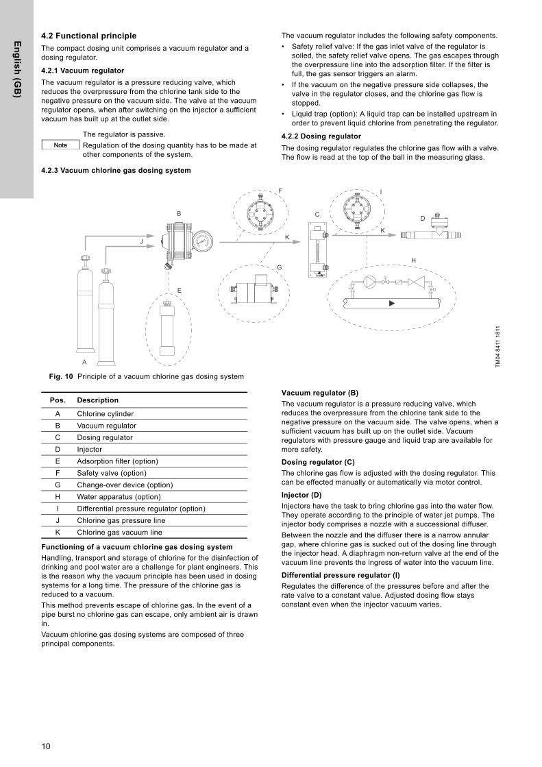
4.2.3 Vacuum chlorine gas dosing system
Fig. 10 Principle of a vacuum chlorine gas dosing system
Functioning of a vacuum chlorine gas dosing system
Handling, transport and storage of chlorine for the disinfection of drinking and pool water are a challenge for plant engineers. This is the reason why the vacuum principle has been used in dosing systems for a long time. The pressure of the chlorine gas is reduced to a vacuum.
This method prevents escape of chlorine gas. In the event of a pipe burst no chlorine gas can escape, only ambient air is drawn in.
Vacuum chlorine gas dosing systems are composed of three principal components.
Vacuum regulator (B)
The vacuum regulator is a pressure reducing valve, which reduces the overpressure from the chlorine tank side to the negative pressure on the vacuum side. The valve opens, when a sufficient vacuum has built up on the outlet side. Vacuum regulators with pressure gauge and liquid trap are available for more safety.
Dosing regulator (C)
The chlorine gas flow is adjusted with the dosing regulator. This can be effected manually or automatically via motor control.
Injector (D)
Injectors have the task to bring chlorine gas into the water flow. They operate according to the principle of water jet pumps. The injector body comprises a nozzle with a successional diffuser.
Between the nozzle and the diffuser there is a narrow annular gap, where chlorine gas is sucked out of the dosing line through the injector head. A diaphragm non-return valve at the end of the vacuum line prevents the ingress of water into the vacuum line.
Differential pressure regulator (I)
Regulates the difference of the pressures before and after the rate valve to a constant value. Adjusted dosing flow stays constant even when the injector vacuum varies.
NoteThe regulator is passive.
Regulation of the dosing quantity has to be made at other components of the system.
TM
04
84
11 1
811
A
B
E
G
F
C
H
D
I
JK
K
Pos. Description
A Chlorine cylinder
B Vacuum regulator
C Dosing regulator
D Injector
E Adsorption filter (option)
F Safety valve (option)
G Change-over device (option)
H Water apparatus (option)
I Differential pressure regulator (option)
J Chlorine gas pressure line
K Chlorine gas vacuum line
10

En
gli
sh
(G
B)
5. Assembly and installation5.1 Selection of vacuum lines
The vacuum needed for the transport of chlorine gas is built up by the injector, and maintained by the vacuum lines. Rigid PVC pipes or flexible PE hoses are used as vacuum lines.
The following tables show the recommended diameter of vacuum lines, depending on the line length and dosing quantity.
5.1.1 Vacuum lines between vacuum regulator and dosing regulator
* For the calculation, a pressure loss of p = 12.5 mbar in the vacuum line was assumed.
5.1.2 Vacuum lines between dosing regulator and injector
** For the calculation, a pressure loss of p = 50 mbar in the vacuum line was assumed.
Warning
Observe section 1. Safety instructions.
Max. length [m] of the vacuum lines between vacuum regulator and dosing regulator*
Dosing quantity [g/h]
40 100 250 500 1000 2000 4000
0 DN 8 DN 8 DN 8 DN 8 DN 8 DN 8 DN 10
10 DN 8 DN 8 DN 8 DN 8 DN 8 DN 8 DN 10
20 DN 8 DN 8 DN 8 DN 8 DN 8 DN 10 DN 15
30 DN 8 DN 8 DN 8 DN 8 DN 8 DN 10 DN 15
40 DN 8 DN 8 DN 8 DN 8 DN 8 DN 15 DN 15
50 DN 8 DN 8 DN 8 DN 8 DN 10 DN 15 DN 15
75 DN 8 DN 8 DN 8 DN 8 DN 10 DN 15 DN 15
100 DN 8 DN 8 DN 8 DN 8 DN 10 DN 15 DN 20
Max. length [m] of the vacuum lines between dosing regulator and injector**
Dosing quantity [g/h]
40 100 250 500 1000 2000 4000
0 DN 8 DN 8 DN 8 DN 8 DN 8 DN 8 DN 8
10 DN 8 DN 8 DN 8 DN 8 DN 8 DN 8 DN 8
20 DN 8 DN 8 DN 8 DN 8 DN 8 DN 8 DN 10
30 DN 8 DN 8 DN 8 DN 8 DN 8 DN 8 DN 10
40 DN 8 DN 8 DN 8 DN 8 DN 8 DN 8 DN 10
50 DN 8 DN 8 DN 8 DN 8 DN 8 DN 10 DN 15
75 DN 8 DN 8 DN 8 DN 8 DN 8 DN 10 DN 15
100 DN 8 DN 8 DN 8 DN 8 DN 8 DN 10 DN 15
11
En
glis
h (G
B)
5.2 Connecting the compact dosing unit
Fig. 11 Connections
1. Position chlorine containers and protect them from turning over or rolling away.
2. Clean and dry the connections, if necessary.
3. Remove the protective cap from the container valve.
4. Insert the gasket at the pressure connection of the compact dosing unit.
– Replace the filter at the pressure connection, if necessary.
5. Mount the compact dosing unit onto the container connection.
6. Connect the overpressure line (2) to the adsorption filter.
7. Connect the vacuum line to the injector.
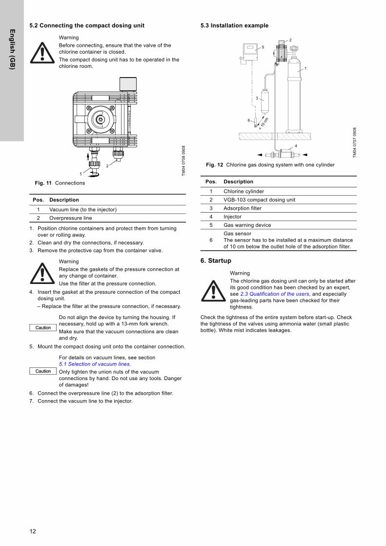
5.3 Installation example
Fig. 12 Chlorine gas dosing system with one cylinder
6. Startup
Check the tightness of the entire system before start-up. Check the tightness of the valves using ammonia water (small plastic bottle). White mist indicates leakages.
Warning
Before connecting, ensure that the valve of the chlorine container is closed.
The compact dosing unit has to be operated in the chlorine room.
TM
04
07
08
09
08
Pos. Description
1 Vacuum line (to the injector)
2 Overpressure line
Warning
Replace the gaskets of the pressure connection at any change of container.
Use the filter at the pressure connection.
Caution
Do not align the device by turning the housing. If necessary, hold up with a 13-mm fork wrench.
Make sure that the vacuum connections are clean and dry.
Caution
For details on vacuum lines, see section 5.1 Selection of vacuum lines.
Only tighten the union nuts of the vacuum connections by hand. Do not use any tools. Danger of damages!
1
2
TM
04
07
07
09
08
Pos. Description
1 Chlorine cylinder
2 VGB-103 compact dosing unit
3 Adsorption filter
4 Injector
5 Gas warning device
6Gas sensorThe sensor has to be installed at a maximum distance of 10 cm below the outlet hole of the adsorption filter.
Warning
The chlorine gas dosing unit can only be started after its good condition has been checked by an expert, see 2.3 Qualification of the users, and especially gas-leading parts have been checked for their tightness.
1
2
3
4
5
6
< 10
cm
12
En
gli
sh
(G
B)
6.1 Checking the tightness
Due to the heavy corrosiveness of humid chlorine gas, all leakages increase quickly. Therefore, even the smallest leakage must be eliminated immediately.
6.1.1 Checking the chlorine solution lines and the injector
Observe the installation and operating instructions of the injector.
6.1.2 Checking the vacuum lines
Vacuum lines are all lines between vacuum regulator and injector.
1. Close all chlorine container valves.
2. Close the rate valve.
3. Open the shut-off valve at the injection unit.
4. Open the motive water valve.
5. Switch on the booster pump.
6. Open the rate valve.
– If the floater shows a gas flow, or the vacuummeter indicates more than -9 m water column, the vacuum lines are leaky.
7. Close the rate valve.
8. Switch off the booster pump.
9. Close the motive water valve.
10. Close the shut-off valve at the injection unit.
11. Check the vacuum lines and connections. Re-tighten them carefully, if necessary.
12. Repeat the tightness check.
– If the floater shows no gas flow, and the vacuummeter indicates -9 m water column or less, the vacuum lines are tight.
6.1.3 Checking the gas pressure lines
Gas pressure lines are all lines leading from the chlorine containers to the vacuum regulator.
1. If the system is equipped with a nitrogen rinsing device, check the tightness roughly with nitrogen.
2. Detailed checking is made with ammonia.
Checking the tightness with nitrogen
1. Close all chlorine container valves.
2. Open container connection valves and all shut-off valves up to the chlorine gas dosing system.
3. Open the connection valve of the nitrogen cylinder.
4. Slowly open the valve of the nitrogen cylinder, until the lines have a pressure of about 10 bar (read at the pressure gauge of the vacuum regulator).
5. Apply soap water to all components under pressure.
– If bubbles form and/or pressure drops at the pressure gauge, the pressure lines are leaky.
6. Depressurise the system.
7. Eliminate the leakage.
8. Repeat the tightness check.
9. If no bubbles form, and the pressure at the pressure gauge does not drop significantly within one hour, the pressure lines are tight.
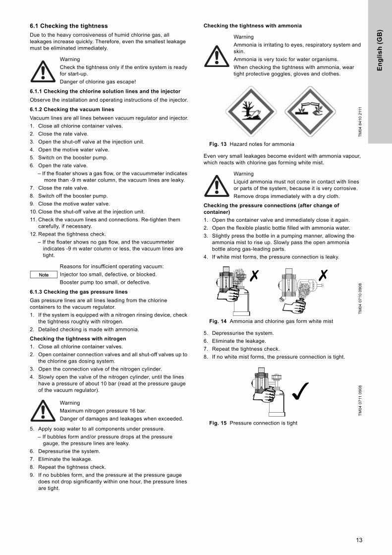
Checking the tightness with ammonia
Fig. 13 Hazard notes for ammonia
Even very small leakages become evident with ammonia vapour, which reacts with chlorine gas forming white mist.
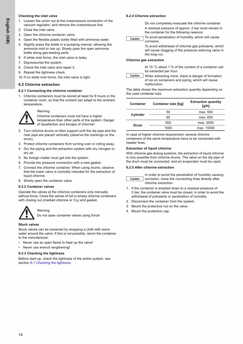
Checking the pressure connections (after change of container)
1. Open the container valve and immediately close it again.
2. Open the flexible plastic bottle filled with ammonia water.
3. Slightly press the bottle in a pumping manner, allowing the ammonia mist to rise up. Slowly pass the open ammonia bottle along gas-leading parts.
4. If white mist forms, the pressure connection is leaky.
Fig. 14 Ammonia and chlorine gas form white mist
5. Depressurise the system.
6. Eliminate the leakage.
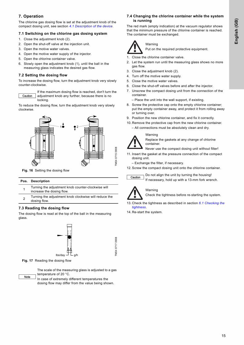
7. Repeat the tightness check.
8. If no white mist forms, the pressure connection is tight.
Fig. 15 Pressure connection is tight
Warning
Check the tightness only if the entire system is ready for start-up.
Danger of chlorine gas escape!
Note
Reasons for insufficient operating vacuum:
Injector too small, defective, or blocked.
Booster pump too small, or defective.
Warning
Maximum nitrogen pressure 16 bar.
Danger of damages and leakages when exceeded.
Warning
Ammonia is irritating to eyes, respiratory system and skin.
Ammonia is very toxic for water organisms.
When checking the tightness with ammonia, wear tight protective goggles, gloves and clothes.
TM
04
84
10
211
1
Warning
Liquid ammonia must not come in contact with lines or parts of the system, because it is very corrosive.
Remove drops immediately with a dry cloth.
TM
04
07
10
09
08
TM
04
07
11 0
90
8
13
En
glis
h (G
B)
Checking the inlet valve
1. Loosen the union nut at the overpressure connection of the vacuum regulator, and remove the overpressure line.
2. Close the inlet valve.
3. Open the chlorine container valve.
4. Open the flexible plastic bottle filled with ammonia water.
5. Slightly press the bottle in a pumping manner, allowing the ammonia mist to rise up. Slowly pass the open ammonia bottle along gas-leading parts.
6. If white mist forms, the inlet valve is leaky.
7. Depressurise the system.
8. Check the inlet valve and repair it.
9. Repeat the tightness check.
10. If no white mist forms, the inlet valve is tight.
6.2 Chlorine extraction
6.2.1 Connecting the chlorine container
1. Chlorine containers must be stored at least for 8 hours in the container room, so that the content can adapt to the ambient temperature.
2. Turn chlorine drums on their support until the dip pipe and the riser pipe are placed vertically (observe the markings on the drum).
3. Protect chlorine containers from turning over or rolling away.
4. Dry the piping and the extraction system with dry nitrogen or dry air.
5. No foreign matter must get into the system.
6. Provide the pressure connection with a new gasket.
7. Connect the chlorine container. When using drums, observe that the lower valve is normally intended for the extraction of liquid chlorine.
8. Slowly open the container valve.
6.2.2 Container valves
Operate the valves at the chlorine containers only manually without force. Close the valves of full or empty chlorine containers with closing nut (marked chlorine or Cl2) and gasket.
Stuck valves
Stuck valves can be loosened by wrapping a cloth with warm water around the valve. If this is not possible, return the container to the manufacturer.
• Never use an open flame to heat up the valve!
• Never use wrench lengthening!
6.2.3 Checking the tightness
Before start-up, check the tightness of the entire system, see section 6.1 Checking the tightness.
6.2.4 Chlorine extraction
Chlorine gas extraction
The table shows the maximum extraction quantity depending on the used container size.
In case of higher chlorine requirement, several chlorine containers of the same temperature have to be connected with header lines.
Extraction of liquid chlorine
With chlorine gas dosing systems, the extraction of liquid chlorine is only possible from chlorine drums. The valve on the dip pipe of the drum must be connected, and an evaporator must be used.
6.2.5 After chlorine extraction
1. If the container is emptied down to a residual pressure of 2 bar, the container valve must be closed, in order to avoid the withdrawal of pollutants or penetration of humidity.
2. Disconnect the container from the system.
3. Mount the protective nut on the valve.
4. Mount the protective cap.
Warning
Chlorine containers must not have a higher temperature than other parts of the system. Danger of liquefaction and escape of chlorine!
Warning
Do not open container valves using force!
Caution
Do not completely evacuate the chlorine container.
A residual pressure of approx. 2 bar must remain in the container for the following reasons:
To avoid penetration of humidity, which will cause corrosion.
To avoid withdrawal of chlorine gas pollutants, which will cause clogging of the pressure reducing valve in the long run.
Caution
At 15 °C about 1 % of the content of a container can be extracted per hour.
When extracting more, there is danger of formation of ice on containers and piping, which will cause malfunction.
Container Container size [kg]Extraction quantity
[g/h]
Cylinder50 max. 500
65 max. 650
Drum500 max. 5000
1000 max. 10000
CautionIn order to avoid the penetration of humidity causing corrosion, close the connecting lines directly after chlorine extraction.
14
En
gli
sh
(G
B)
7. OperationThe chlorine gas dosing flow is set at the adjustment knob of the compact dosing unit, see section 4.1 Description of the device.
7.1 Switching on the chlorine gas dosing system
1. Close the adjustment knob (2).
2. Open the shut-off valve at the injection unit.
3. Open the motive water valves.
4. Open the motive water supply of the injector.
5. Open the chlorine container valve.
6. Slowly open the adjustment knob (1), until the ball in the measuring glass indicates the desired gas flow.
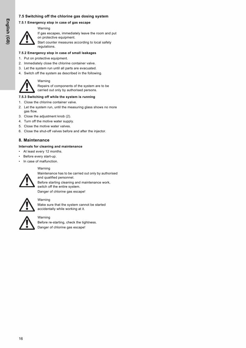
7.2 Setting the dosing flow
To increase the dosing flow, turn the adjustment knob very slowly counter-clockwise.
To reduce the dosing flow, turn the adjustment knob very slowly clockwise.
Fig. 16 Setting the dosing flow
7.3 Reading the dosing flow
The dosing flow is read at the top of the ball in the measuring glass.
Fig. 17 Reading the dosing flow
7.4 Changing the chlorine container while the system is running
The red mark (empty indication) at the vacuum regulator shows that the minimum pressure of the chlorine container is reached. The container must be exchanged.
1. Close the chlorine container valve.
2. Let the system run until the measuring glass shows no more gas flow.
3. Close the adjustment knob (2).
4. Turn off the motive water supply.
5. Close the motive water valves.
6. Close the shut-off valves before and after the injector.
7. Unscrew the compact dosing unit from the connection of the container.
– Place the unit into the wall support, if existing.
8. Screw the protective cap onto the empty chlorine container; put the empty container away, and protect it from rolling away or turning over.
9. Position the new chlorine container, and fix it correctly.
10. Remove the protective cap from the new chlorine container.
– All connections must be absolutely clean and dry.
11. Insert the gasket at the pressure connection of the compact dosing unit.
– Exchange the filter, if necessary.
12. Screw the compact dosing unit onto the chlorine container.
13. Check the tightness as described in section 6.1 Checking the tightness.
14. Re-start the system.
CautionIf the maximum dosing flow is reached, don't turn the adjustment knob any further, because there is no locking.
TM
04
07
15
09
08
Pos. Description
1Turning the adjustment knob counter-clockwise will increase the dosing flow.
2Turning the adjustment knob clockwise will reduce the dosing flow.
TM
04
07
17
09
08
Note
The scale of the measuring glass is adjusted to a gas temperature of 20 °C.
In case of extremely different temperatures the dosing flow may differ from the value being shown.
1 2
g/hlbs/day
Warning
Put on the required protective equipment.
Warning
Replace the gaskets at any change of chlorine container.
Never use the compact dosing unit without filter!
CautionDo not align the unit by turning the housing!
If necessary, hold up with a 13-mm fork wrench.
Warning
Check the tightness before re-starting the system.
15
En
glis
h (G
B)
7.5 Switching off the chlorine gas dosing system
7.5.1 Emergency stop in case of gas escape
7.5.2 Emergency stop in case of small leakages
1. Put on protective equipment.
2. Immediately close the chlorine container valve.
3. Let the system run until all parts are evacuated.
4. Switch off the system as described in the following.
7.5.3 Switching off while the system is running
1. Close the chlorine container valve.
2. Let the system run, until the measuring glass shows no more gas flow.
3. Close the adjustment knob (2).
4. Turn off the motive water supply.
5. Close the motive water valves.
6. Close the shut-off valves before and after the injector.
8. Maintenance
Intervals for cleaning and maintenance
• At least every 12 months.
• Before every start-up.
• In case of malfunction.
Warning
If gas escapes, immediately leave the room and put on protective equipment.
Start counter measures according to local safety regulations.
Warning
Repairs of components of the system are to be carried out only by authorised persons.
Warning
Maintenance has to be carried out only by authorised and qualified personnel.
Before starting cleaning and maintenance work, switch off the entire system.
Danger of chlorine gas escape!
Warning
Make sure that the system cannot be started accidentally while working at it.
Warning
Before re-starting, check the tightness.
Danger of chlorine gas escape!
16
En
gli
sh
(G
B)
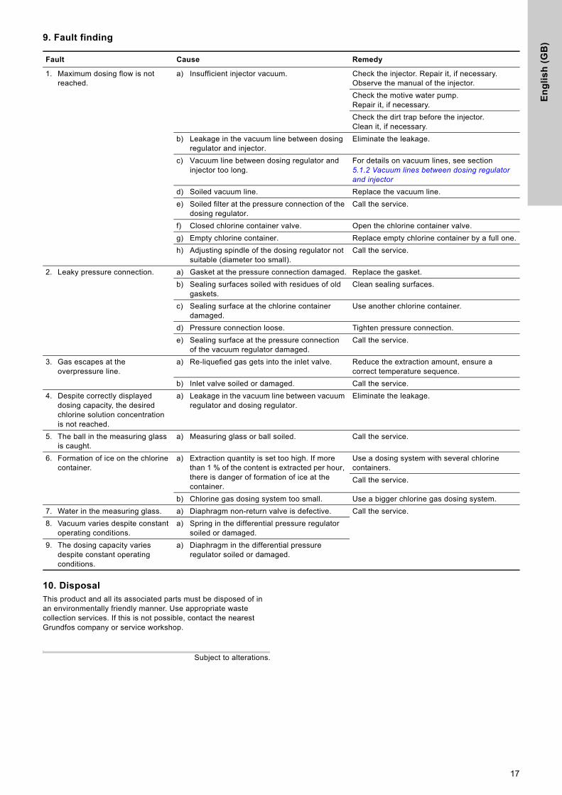
9. Fault finding10. DisposalThis product and all its associated parts must be disposed of in an environmentally friendly manner. Use appropriate waste collection services. If this is not possible, contact the nearest Grundfos company or service workshop.
Subject to alterations.
Fault Cause Remedy
1. Maximum dosing flow is not reached.
a) Insufficient injector vacuum. Check the injector. Repair it, if necessary. Observe the manual of the injector.
Check the motive water pump.Repair it, if necessary.
Check the dirt trap before the injector. Clean it, if necessary.
b) Leakage in the vacuum line between dosing regulator and injector.
Eliminate the leakage.
c) Vacuum line between dosing regulator and injector too long.
For details on vacuum lines, see section 5.1.2 Vacuum lines between dosing regulator and injector
d) Soiled vacuum line. Replace the vacuum line.
e) Soiled filter at the pressure connection of the dosing regulator.
Call the service.
f) Closed chlorine container valve. Open the chlorine container valve.
g) Empty chlorine container. Replace empty chlorine container by a full one.
h) Adjusting spindle of the dosing regulator not suitable (diameter too small).
Call the service.
2. Leaky pressure connection. a) Gasket at the pressure connection damaged. Replace the gasket.
b) Sealing surfaces soiled with residues of old gaskets.
Clean sealing surfaces.
c) Sealing surface at the chlorine container damaged.
Use another chlorine container.
d) Pressure connection loose. Tighten pressure connection.
e) Sealing surface at the pressure connection of the vacuum regulator damaged.
Call the service.
3. Gas escapes at the overpressure line.
a) Re-liquefied gas gets into the inlet valve. Reduce the extraction amount, ensure a correct temperature sequence.
b) Inlet valve soiled or damaged. Call the service.
4. Despite correctly displayed dosing capacity, the desired chlorine solution concentration is not reached.
a) Leakage in the vacuum line between vacuum regulator and dosing regulator.
Eliminate the leakage.
5. The ball in the measuring glass is caught.
a) Measuring glass or ball soiled. Call the service.
6. Formation of ice on the chlorine container.
a) Extraction quantity is set too high. If more than 1 % of the content is extracted per hour, there is danger of formation of ice at the container.
Use a dosing system with several chlorine containers.
Call the service.
b) Chlorine gas dosing system too small. Use a bigger chlorine gas dosing system.
7. Water in the measuring glass. a) Diaphragm non-return valve is defective. Call the service.
8. Vacuum varies despite constant operating conditions.
a) Spring in the differential pressure regulator soiled or damaged.
9. The dosing capacity varies despite constant operating conditions.
a) Diaphragm in the differential pressure regulator soiled or damaged.
17
De
cla
ratio
n o
f co
nfo
rmity
18
Declaration of conformity 1
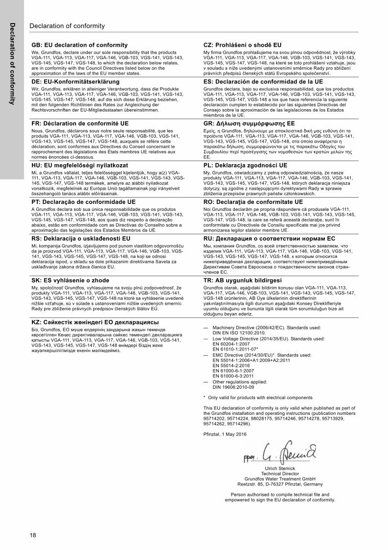
GB: EU declaration of conformityWe, Grundfos, declare under our sole responsibility that the products VGA-111, VGA-113, VGA-117, VGA-146, VGB-103, VGS-141, VGS-143, VGS-145, VGS-147, VGS-148, to which the declaration below relates, are in conformity with the Council Directives listed below on the approximation of the laws of the EU member states.
CZ: Prohlášení o shodě EUMy firma Grundfos prohlašujeme na svou plnou odpovědnost, že výrobky VGA-111, VGA-113, VGA-117, VGA-146, VGB-103, VGS-141, VGS-143, VGS-145, VGS-147, VGS-148, na které se toto prohlášení vztahuje, jsou v souladu s níže uvedenými ustanoveními směrnice Rady pro sblížení právních předpisů členských států Evropského společenství.
DE: EU-KonformitätserklärungWir, Grundfos, erklären in alleiniger Verantwortung, dass die Produkte VGA-111, VGA-113, VGA-117, VGA-146, VGB-103, VGS-141, VGS-143, VGS-145, VGS-147, VGS-148, auf die sich diese Erklärung beziehen, mit den folgenden Richtlinien des Rates zur Angleichung der Rechtsvorschriften der EU-Mitgliedsstaaten übereinstimmen.
ES: Declaración de conformidad de la UEGrundfos declara, bajo su exclusiva responsabilidad, que los productos VGA-111, VGA-113, VGA-117, VGA-146, VGB-103, VGS-141, VGS-143, VGS-145, VGS-147, VGS-148 a los que hace referencia la siguiente declaración cumplen lo establecido por las siguientes Directivas del Consejo sobre la aproximación de las legislaciones de los Estados miembros de la UE.
FR: Déclaration de conformité UENous, Grundfos, déclarons sous notre seule responsabilité, que les produits VGA-111, VGA-113, VGA-117, VGA-146, VGB-103, VGS-141, VGS-143, VGS-145, VGS-147, VGS-148, auxquels se réfère cette déclaration, sont conformes aux Directives du Conseil concernant le rapprochement des législations des États membres UE relatives aux normes énoncées ci-dessous.
GR: ∆ήλωση συμμόρφωσης ΕΕΕμείς, η Grundfos, δηλώνουμε με αποκλειστικά δική μας ευθύνη ότι τα προϊόντα VGA-111, VGA-113, VGA-117, VGA-146, VGB-103, VGS-141, VGS-143, VGS-145, VGS-147, VGS-148, στα οποία αναφέρεται η παρακάτω δήλωση, συμμορφώνονται με τις παρακάτω Οδηγίες του Συμβουλίου περί προσέγγισης των νομοθεσιών των κρατών μελών της ΕΕ.
HU: EU megfelelőségi nyilatkozatMi, a Grundfos vállalat, teljes felelősséggel kijelentjük, hogy a(z) VGA-111, VGA-113, VGA-117, VGA-146, VGB-103, VGS-141, VGS-143, VGS-145, VGS-147, VGS-148 termékek, amelyre az alábbi nyilatkozat vonatkozik, megfelelnek az Európai Unió tagállamainak jogi irányelveit összehangoló tanács alábbi előírásainak.
PL: Deklaracja zgodności UEMy, Grundfos, oświadczamy z pełną odpowiedzialnością, że nasze produkty VGA-111, VGA-113, VGA-117, VGA-146, VGB-103, VGS-141, VGS-143, VGS-145, VGS-147, VGS-148, których deklaracja niniejsza dotyczy, są zgodne z następującymi dyrektywami Rady w sprawie zbliżenia przepisów prawnych państw członkowskich.
PT: Declaração de conformidade UEA Grundfos declara sob sua única responsabilidade que os produtos VGA-111, VGA-113, VGA-117, VGA-146, VGB-103, VGS-141, VGS-143, VGS-145, VGS-147, VGS-148, aos quais diz respeito a declaração abaixo, estão em conformidade com as Directivas do Conselho sobre a aproximação das legislações dos Estados Membros da UE.
RO: Declaraţia de conformitate UENoi Grundfos declarăm pe propria răspundere că produsele VGA-111, VGA-113, VGA-117, VGA-146, VGB-103, VGS-141, VGS-143, VGS-145, VGS-147, VGS-148, la care se referă această declaraţie, sunt în conformitate cu Directivele de Consiliu specificate mai jos privind armonizarea legilor statelor membre UE.
RS: Deklaracija o usklađenosti EUMi, kompanija Grundfos, izjavljujemo pod punom vlastitom odgovornošću da je proizvod VGA-111, VGA-113, VGA-117, VGA-146, VGB-103, VGS-141, VGS-143, VGS-145, VGS-147, VGS-148, na koji se odnosi deklaracija ispod, u skladu sa dole prikazanim direktivama Saveta za usklađivanje zakona država članica EU.
RU: Декларация о соответствии нормам ЕСМы, компания Grundfos, со всей ответственностью заявляем, что изделия VGA-111, VGA-113, VGA-117, VGA-146, VGB-103, VGS-141, VGS-143, VGS-145, VGS-147, VGS-148, к которым относится нижеприведённая декларация, соответствуют нижеприведённым Директивам Совета Евросоюза о тождественности законов стран-членов ЕС.
SK: ES vyhlásenie o zhodeMy, spoločnosť Grundfos, vyhlasujeme na svoju plnú zodpovednosť, že produkty VGA-111, VGA-113, VGA-117, VGA-146, VGB-103, VGS-141, VGS-143, VGS-145, VGS-147, VGS-148 na ktoré sa vyhlásenie uvedené nižšie vzťahuje, sú v súlade s ustanoveniami nižšie uvedených smerníc Rady pre zblíženie právnych predpisov členských štátov EÚ.
TR: AB uygunluk bildirgesiGrundfos olarak, aşağıdaki bildirim konusu olan VGA-111, VGA-113, VGA-117, VGA-146, VGB-103, VGS-141, VGS-143, VGS-145, VGS-147, VGS-148 ürünlerinin, AB Üye ülkelerinin direktiflerinin yakınlaştırılmasıyla ilgili durumun aşağıdaki Konsey Direktifleriyle uyumlu olduğunu ve bununla ilgili olarak tüm sorumluluğun bize ait olduğunu beyan ederiz.
KZ: Сəйкестік жөніндегі ЕО декларациясыБіз, Grundfos, ЕО мүше елдерінің заңдарына жақын төменде көрсетілген Кеңес директиваларына сəйкес төмендегі декларацияға қатысты VGA-111, VGA-113, VGA-117, VGA-146, VGB-103, VGS-141, VGS-143, VGS-145, VGS-147, VGS-148 өнімдері біздің жеке жауапкершілігімізде екенін мəлімдейміз.
— Machinery Directive (2006/42/EC). Standards used:DIN EN ISO 12100:2010.
— Low Voltage Directive (2014/35/EU). Standards used:EN 60204-1:2007EN 61010-1:2011-07*
— EMC Directive (2014/30/EU)*. Standards used: EN 55014-1:2006+A1:2009+A2:2011EN 55014-2:2016EN 61000-6-1:2007EN 61000-6-3:2011
— Other regulations applied:DIN 19606:2010-09
* Only valid for products with electrical components
This EU declaration of conformity is only valid when published as part of the Grundfos installation and operating instructions (publication numbers 95714202, 95714224, 98028175, 95714246, 95714278, 95713929, 95714262, 95714296).
Pfinztal, 1 May 2016
Ulrich StemickTechnical Director
Grundfos Water Treatment GmbHReetzstr. 85, D-76327 Pfinztal, Germany
Person authorised to compile technical file andempowered to sign the EU declaration of conformity.
Op
era
tin
g m
an
ua
l E
AC
19
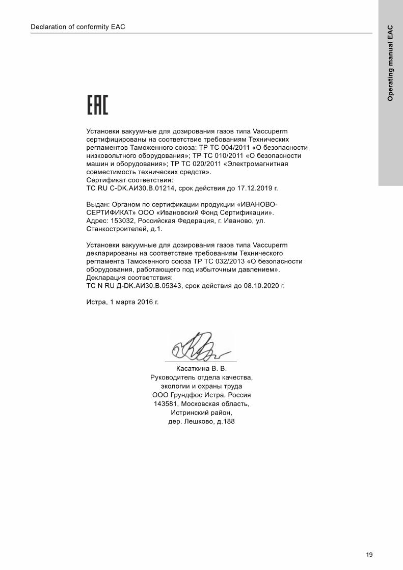
Declaration of conformity EAC 2
Установки вакуумные для дозирования газов типа Vaccuperm сертифицированы на соответствие требованиям Технических регламентов Таможенного союза: ТР ТС 004/2011 «О безопасности низковольтного оборудования»; ТР ТС 010/2011 «О безопасности машин и оборудования»; ТР ТС 020/2011 «Электромагнитная совместимость технических средств».Сертификат соответствия:TC RU C-DK.АИ30.В.01214, срок действия до 17.12.2019 г.
Выдан: Органом по сертификации продукции «ИВАНОВО-СЕРТИФИКАТ» ООО «Ивановский Фонд Сертификации». Адрес: 153032, Российская Федерация, г. Иваново, ул. Станкостроителей, д.1.
Установки вакуумные для дозирования газов типа Vaccuperm декларированы на соответствие требованиям Технического регламента Таможенного союза ТР ТС 032/2013 «О безопасности оборудования, работающего под избыточным давлением».Декларация соответствия:TC N RU Д-DK.АИ30.В.05343, срок действия до 08.10.2020 г.
Истра, 1 марта 2016 г.
Касаткина В. В.Руководитель отдела качества,
экологии и охраны трудаООО Грундфос Истра, Россия143581, Московская область,
Истринский район,дер. Лешково, д.188

20
Gru
nd
fos
co
mp
anie
s
ArgentinaBombas GRUNDFOS de Argentina S.A.Ruta Panamericana km. 37.500 Centro Industrial Garin1619 - Garin Pcia. de B.A.Phone: +54-3327 414 444Telefax: +54-3327 411 111
AustraliaGRUNDFOS Pumps Pty. Ltd. P.O. Box 2040 Regency Park South Australia 5942 Phone: +61-8-8461-4611 Telefax: +61-8-8340 0155
AustriaGRUNDFOS Pumpen Vertrieb Ges.m.b.H.Grundfosstraße 2 A-5082 Grödig/Salzburg Tel.: +43-6246-883-0 Telefax: +43-6246-883-30
BelgiumN.V. GRUNDFOS Bellux S.A. Boomsesteenweg 81-83 B-2630 Aartselaar Tél.: +32-3-870 7300 Télécopie: +32-3-870 7301
BelarusПредставительство ГРУНДФОС в Минске220125, Минскул. Шафарнянская, 11, оф. 56Тел.: +7 (375 17) 286 39 72, 286 39 73Факс: +7 (375 17) 286 39 71E-mail: [email protected]
Bosnia/HerzegovinaGRUNDFOS SarajevoTrg Heroja 16,BiH-71000 SarajevoPhone: +387 33 713 290Telefax: +387 33 659 079e-mail: [email protected]
BrazilBOMBAS GRUNDFOS DO BRASILAv. Humberto de Alencar Castelo Branco, 630CEP 09850 - 300São Bernardo do Campo - SPPhone: +55-11 4393 5533Telefax: +55-11 4343 5015
BulgariaGrundfos Bulgaria EOODSlatina DistrictIztochna Tangenta street no. 100BG - 1592 SofiaTel. +359 2 49 22 200Fax. +359 2 49 22 201email: [email protected]
CanadaGRUNDFOS Canada Inc. 2941 Brighton Road Oakville, Ontario L6H 6C9 Phone: +1-905 829 9533 Telefax: +1-905 829 9512
ChinaGrundfos AlldosDosing & DisinfectionALLDOS (Shanghai) Water Technology Co. Ltd.West Unit, 1 Floor, No. 2 Building (T 4-2)278 Jinhu Road, Jin Qiao Export Processing ZonePudong New Area Shanghai, 201206Phone: +86 21 5055 1012Telefax: +86 21 5032 0596E-mail: [email protected]
ChinaGRUNDFOS Pumps (Shanghai) Co. Ltd.10F The Hub, No. 33 Suhong RoadMinhang DistrictShanghai 201106PRCPhone: +86-21 6122 5222 Telefax: +86-21 6122 5333
COLOMBIAGRUNDFOS Colombia S.A.S.Km 1.5 vía Siberia-Cota Conj. Potrero Chico,Parque Empresarial Arcos de Cota Bod. 1A.Cota, CundinamarcaPhone: +57(1)-2913444Telefax: +57(1)-8764586
CroatiaGRUNDFOS CROATIA d.o.o.Cebini 37, BuzinHR-10010 ZagrebPhone: +385 1 6595 400 Telefax: +385 1 6595 499www.hr.grundfos.com
GRUNDFOS Sales Czechia and Slovakia s.r.o.Čapkovského 21779 00 OlomoucPhone: +420-585-716 111
DenmarkGRUNDFOS DK A/S Martin Bachs Vej 3 DK-8850 Bjerringbro Tlf.: +45-87 50 50 50 Telefax: +45-87 50 51 51 E-mail: [email protected]/DK
EstoniaGRUNDFOS Pumps Eesti OÜPeterburi tee 92G11415 TallinnTel: + 372 606 1690Fax: + 372 606 1691
FinlandOY GRUNDFOS Pumput AB Trukkikuja 1FI-01360 Vantaa Phone: +358-(0)207 889 500
FrancePompes GRUNDFOS Distribution S.A. Parc d’Activités de Chesnes 57, rue de Malacombe F-38290 St. Quentin Fallavier (Lyon) Tél.: +33-4 74 82 15 15 Télécopie: +33-4 74 94 10 51
GermanyGRUNDFOS Water Treatment GmbHReetzstraße 85D-76327 Pfinztal (Söllingen)Tel.: +49 7240 61-0 Telefax: +49 7240 61-177E-mail: [email protected]
GermanyGRUNDFOS GMBHSchlüterstr. 3340699 ErkrathTel.: +49-(0) 211 929 69-0 Telefax: +49-(0) 211 929 69-3799E-mail: [email protected] in Deutschland:E-mail: [email protected]
GreeceGRUNDFOS Hellas A.E.B.E. 20th km. Athinon-Markopoulou Av. P.O. Box 71 GR-19002 Peania Phone: +0030-210-66 83 400 Telefax: +0030-210-66 46 273
Hong KongGRUNDFOS Pumps (Hong Kong) Ltd. Unit 1, Ground floor Siu Wai Industrial Centre 29-33 Wing Hong Street & 68 King Lam Street, Cheung Sha Wan Kowloon Phone: +852-27861706 / 27861741 Telefax: +852-27858664
HungaryGRUNDFOS Hungária Kft.Park u. 8H-2045 Törökbálint, Phone: +36-23 511 110Telefax: +36-23 511 111
IndiaGRUNDFOS Pumps India Private Limited118 Old Mahabalipuram RoadThoraipakkamChennai 600 097Phone: +91-44 4596 6800
IndonesiaPT. GRUNDFOS POMPAGraha Intirub Lt. 2 & 3Jln. Cililitan Besar No.454. Makasar, Jakarta TimurID-Jakarta 13650Phone: +62 21-469-51900Telefax: +62 21-460 6910 / 460 6901
IrelandGRUNDFOS (Ireland) Ltd. Unit A, Merrywell Business ParkBallymount Road LowerDublin 12 Phone: +353-1-4089 800 Telefax: +353-1-4089 830
ItalyGRUNDFOS Pompe Italia S.r.l. Via Gran Sasso 4I-20060 Truccazzano (Milano)Tel.: +39-02-95838112 Telefax: +39-02-95309290 / 95838461
JapanGRUNDFOS Pumps K.K.1-2-3, Shin-Miyakoda, Kita-kuHamamatsu431-2103 JapanPhone: +81 53 428 4760Telefax: +81 53 428 5005
KoreaGRUNDFOS Pumps Korea Ltd.6th Floor, Aju Building 679-5Yeoksam-dong, Kangnam-ku, 135-916Seoul, KoreaPhone: +82-2-5317 600Telefax: +82-2-5633 725
LatviaSIA GRUNDFOS Pumps Latvia Deglava biznesa centrsAugusta Deglava ielā 60, LV-1035, Rīga,Tālr.: + 371 714 9640, 7 149 641Fakss: + 371 914 9646
LithuaniaGRUNDFOS Pumps UABSmolensko g. 6LT-03201 VilniusTel: + 370 52 395 430Fax: + 370 52 395 431
MalaysiaGRUNDFOS Pumps Sdn. Bhd.7 Jalan Peguam U1/25Glenmarie Industrial Park40150 Shah AlamSelangor Phone: +60-3-5569 2922Telefax: +60-3-5569 2866
MexicoBombas GRUNDFOS de México S.A. de C.V. Boulevard TLC No. 15Parque Industrial Stiva AeropuertoApodaca, N.L. 66600Phone: +52-81-8144 4000 Telefax: +52-81-8144 4010
NetherlandsGRUNDFOS NetherlandsVeluwezoom 351326 AE AlmerePostbus 22015 1302 CA ALMERE Tel.: +31-88-478 6336 Telefax: +31-88-478 6332 E-mail: [email protected]
New ZealandGRUNDFOS Pumps NZ Ltd.17 Beatrice Tinsley CrescentNorth Harbour Industrial EstateAlbany, AucklandPhone: +64-9-415 3240Telefax: +64-9-415 3250
NorwayGRUNDFOS Pumper A/S Strømsveien 344 Postboks 235, Leirdal N-1011 Oslo Tlf.: +47-22 90 47 00 Telefax: +47-22 32 21 50
PolandGRUNDFOS Pompy Sp. z o.o.ul. Klonowa 23Baranowo k. PoznaniaPL-62-081 PrzeźmierowoTel: (+48-61) 650 13 00Fax: (+48-61) 650 13 50
PortugalBombas GRUNDFOS Portugal, S.A. Rua Calvet de Magalhães, 241Apartado 1079P-2770-153 Paço de ArcosTel.: +351-21-440 76 00Telefax: +351-21-440 76 90
RomaniaGRUNDFOS Pompe România SRLBd. Biruintei, nr 103 Pantelimon county IlfovPhone: +40 21 200 4100Telefax: +40 21 200 4101E-mail: [email protected]
RussiaООО Грундфосул. Школьная, 39-41Москва, RU-109544, RussiaТел. (+7) 495 737 30 00, 564 8800Факс (+7) 495 737 75 36, 564 8811E-mail [email protected]
Serbia GRUNDFOS Predstavništvo BeogradDr. Milutina Ivkovića 2a/29YU-11000 Beograd Phone: +381 11 26 47 877 / 11 26 47 496Telefax: +381 11 26 48 340
SingaporeGRUNDFOS (Singapore) Pte. Ltd. 25 Jalan Tukang Singapore 619264 Phone: +65-6681 9688 Telefax: +65-6681 9689
SlovakiaGRUNDFOS s.r.o.Prievozská 4D 821 09 BRATISLAVA Phona: +421 2 5020 1426sk.grundfos.com
SloveniaGRUNDFOS LJUBLJANA, d.o.o.Leskoškova 9e, 1122 LjubljanaPhone: +386 (0) 1 568 06 10Telefax: +386 (0)1 568 0619E-mail: [email protected]
South AfricaGrundfos (PTY) Ltd.Corner Mountjoy and George Allen RoadsWilbart Ext. 2Bedfordview 2008Phone: (+27) 11 579 4800Fax: (+27) 11 455 6066E-mail: [email protected]
SpainBombas GRUNDFOS España S.A. Camino de la Fuentecilla, s/n E-28110 Algete (Madrid) Tel.: +34-91-848 8800 Telefax: +34-91-628 0465
SwedenGRUNDFOS AB (Box 333) Lunnagårdsgatan 6 431 24 Mölndal Tel.: +46 31 332 23 000 Telefax: +46 31-331 94 60
SwitzerlandGRUNDFOS ALLDOS International AGSchönmattstraße 4 CH-4153 ReinachTel.: +41-61-717 5555Telefax: +41-61-717 5500E-mail: [email protected]
SwitzerlandGRUNDFOS Pumpen AG Bruggacherstrasse 10 CH-8117 Fällanden/ZH Tel.: +41-44-806 8111 Telefax: +41-44-806 8115
TaiwanGRUNDFOS Pumps (Taiwan) Ltd. 7 Floor, 219 Min-Chuan Road Taichung, Taiwan, R.O.C. Phone: +886-4-2305 0868Telefax: +886-4-2305 0878
ThailandGRUNDFOS (Thailand) Ltd. 92 Chaloem Phrakiat Rama 9 Road,Dokmai, Pravej, Bangkok 10250Phone: +66-2-725 8999Telefax: +66-2-725 8998
TurkeyGRUNDFOS POMPA San. ve Tic. Ltd. Sti.Gebze Organize Sanayi Bölgesi Ihsan dede Caddesi,2. yol 200. Sokak No. 20441490 Gebze/ KocaeliPhone: +90 - 262-679 7979Telefax: +90 - 262-679 7905E-mail: [email protected]
UkraineБізнес Центр ЄвропаСтоличне шосе, 103м. Київ, 03131, Україна Телефон: (+38 044) 237 04 00 Факс.: (+38 044) 237 04 01E-mail: [email protected]
United Arab EmiratesGRUNDFOS Gulf DistributionP.O. Box 16768Jebel Ali Free ZoneDubaiPhone: +971-4- 8815 166Telefax: +971-4-8815 136
United KingdomGRUNDFOS Pumps Ltd. Grovebury Road Leighton Buzzard/Beds. LU7 4TL Phone: +44-1525-850000 Telefax: +44-1525-850011
U.S.A.GRUNDFOS Pumps Corporation 17100 West 118th TerraceOlathe, Kansas 66061Phone: +1-913-227-3400 Telefax: +1-913-227-3500
UzbekistanGrundfos Tashkent, Uzbekistan The Representative Office of Grundfos Kazakhstan in Uzbekistan 38a, Oybek street, Tashkent Телефон: (+998) 71 150 3290 / 71 150 3291Факс: (+998) 71 150 3292
Addresses revised 09.08.2017
95713929 0917
ECM: 1216875 The
nam
e G
rund
fos,
the
Gru
ndfo
s lo
go, a
nd b
e t
hin
k i
nn
ov
ate
are
regi
ster
ed tr
adem
arks
ow
ned
by G
rund
fos
Hol
ding
A/S
or G
rund
fos
A/S,
Den
mar
k. A
ll rig
hts
rese
rved
wor
ldw
ide.
© C
opyr
ight
Gru
ndfo
s H
oldi
ng A
/S
www.grundfos.com