V8 Gen. V Ford Mustang up to 2009
13
V8 Gen. V Ford Mustang up to 2009 N2MB WOT Box Installation Instructions NOTE: If you have a CDI (capacitive discharge ignition system) please contact us at [email protected] for additional instructions. Damage to your WOT Box can occur if the installation is not completed correctly! All stock ignitions are inductive, not capacitive; if you haven’t installed a capacitive ignition system on your vehicle, it doesn’t have one. WARNING: Spark‐based rev‐limiters can damage catalytic converters. If you have catalytic converters on your car, N2MB accepts no responsibility for damage caused by the WOT Box. This being said, many successful installs have been made on Catalytic‐Converter equipped vehicles. Damage usually is only caused by using the launch‐control feature for more than a few seconds, but once again, USE AT YOUR OWN RISK IF YOU HAVE CATALYTIC CONVERTERS! Please visit our website at http://www.n2mb.com for the latest version of the WOT Box software and installation instructions. Solder all joints. The N2MB recommended soldering method is available at http://www.n2mb.com . Use a multimeter to verify all wires before they are cut or tapped into. The colors of wires from model year to model year may differ, and may be different on your car from those described in these instructions. Where discrepancies are known, they are described, but there may be more discrepancies than those listed. The best way to know that you have the right wire is to check the connectivity to the ECU and/or sensor at the pins described. In these instructions, pictures include other aftermarket alterations in addition to the WOT Box. N2MB is not affiliated with these devices. In addition, if you see something that isn’t in your vehicle, don’t worry. Route wires in the manner that you want them to lie permanently before connecting them. Cut wires to length before soldering; avoid coiling wires of excessive length as they can cause noise in the circuit, altering the operation of the WOT Box. Spending some extra time here will enhance the aesthetics of the install. Zip ties are included to secure the wires away from heat, moving parts, sharp edges, or anything else that can damage the wires.
Transcript of V8 Gen. V Ford Mustang up to 2009

V8 Gen. V Ford Mustang up to 2009
N2MB WOT Box Installation Instructions
NOTE: If you have a CDI (capacitive discharge ignition system) please contact us at [email protected] for additional instructions. Damage to your WOT Box can occur if the installation is not completed correctly! All stock ignitions are inductive, not capacitive; if you haven’t installed a capacitive ignition system on your vehicle, it doesn’t have one.
WARNING: Spark‐based rev‐limiters can damage catalytic converters. If you have catalytic converters on your car, N2MB accepts no responsibility for damage caused by the WOT Box. This being said, many successful installs have been made on Catalytic‐Converter equipped vehicles. Damage usually is only caused by using the launch‐control feature for more than a few seconds, but once again, USE AT YOUR OWN RISK IF YOU HAVE CATALYTIC CONVERTERS!
Please visit our website at http://www.n2mb.com for the latest version of the WOT Box software and installation instructions.
Solder all joints. The N2MB recommended soldering method is available at http://www.n2mb.com. Use a multimeter to verify all wires before they are cut or tapped into. The colors of wires from model year to model year may differ, and may be different on your car from those described in these instructions. Where discrepancies are known, they are described, but there may be more discrepancies than those listed. The best way to know that you have the right wire is to check the connectivity to the ECU and/or sensor at the pins described.
In these instructions, pictures include other aftermarket alterations in addition to the WOT Box. N2MB is not affiliated with these devices. In addition, if you see something that isn’t in your vehicle, don’t worry.
Route wires in the manner that you want them to lie permanently before connecting them. Cut wires to length before soldering; avoid coiling wires of excessive length as they can cause noise in the circuit, altering the operation of the WOT Box. Spending some extra time here will enhance the aesthetics of the install. Zip ties are included to secure the wires away from heat, moving parts, sharp edges, or anything else that can damage the wires.
Included in the WOT BOX kit: • WOT Box• Wiring harness• USB to Serial Converter for future
software upgrades• Ground lug• Zip ties• Heat shrink tubing
You will need: • Wire Strippers• Soldering Iron or Station• Metric Socket Set• Sandpaper• Heat Shrink (if more than is included
in the kit is needed)• Electrical tape• Zip Ties (if more than is included in
the kit is needed)• Razor Blade or Sharp Knife• Multimeter or Ohm Meter• Screwdriver or other sharp object• RTV or Hot Glue (optional)• 7/16’ Rubber Grommet with ¼’
internal hole
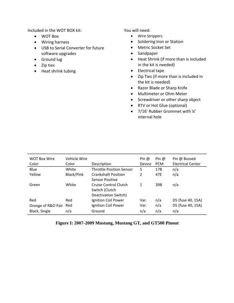
WOT Box Wire Color
Vehicle Wire Color Description
Pin @ Device
Pin @ PCM
Pin @ Bussed Electrical Center
Blue White Throttle Position Sensor 5 17B n/a Black/Pink Crankshaft Position
Sensor Positive 2 47E n/a
White Cruise Control Clutch Switch (Clutch Deactivation Switch)
1 39B n/a
Red Ignition Coil Power Var. n/a D5 (fuse 40, 15A) Red Ignition Coil Power Var. n/a D5 (fuse 40, 15A)
Yellow
Green
Red Orange of R&O Pair Black, Single n/a Ground n/a n/a n/a
Figure I: 2007-2009 Mustang, Mustang GT, and GT500 Pinout

WOT Box Wire Color
Vehicle Wire Color Description
Pin @ Device
Pin @ PCM
Pin @ Bussed Electrical Center
Blue White Throttle Position Sensor 5 17B n/a Black/Pink Crankshaft Position
Sensor Positive 1 47E n/a
White Cruise Control Clutch Switch (Clutch Deactivation Switch)
1 30T n/a
Red Ignition Coil Power 2 n/a C5 NOT B6 (fuse 42, 15A)
Red Ignition Coil Power 2 n/a C5 NOT B6 (fuse 42, 15A)
Yellow
Green
Red
Orange of R&O Pair
Black, Single n/a Ground n/a n/a n/a
Figure II: 2005-2006 Mustang and Mustang GT Pinout
Notes:
1) The letters after the PCM pin numbers indicate which of the three cam lock PCMconnectors the pin is a part of. E is the bottom connector, B is the middle connector,and T is the top connector (see step 10.)
2) Ignition Coil Power is on Pin 2 of each coil for 2007‐2009, and on pin 1 for 2005‐2006.
3) While the wire that the RED/ORANGE WOT Box Pair must be spliced to connects to Pin2 on the coils, it is split after the BEC and connected to Pin 2 on EACH coil. If theRED/ORANGE WOT Box Pair is connected at the coils, each wire of the pair must bespliced to pin 2 of each of the 8 coils. It’s far easier to disassemble the BEC and splice atthe fuse. Pin 2 on a coil may be used, however, for continuity checking to ensure thecorrect wire has been found.
4) These instructions were written with the help of a 2007 GT500. Your vehicle may differslightly.

Figure III: Installation Diagram

1) Open the hood and disconnect the 12V battery negative.
2) Remove passenger side front tire for access. Remove passenger side front fender liner for access
3) Remove passenger side right kick panel.
2)
3)
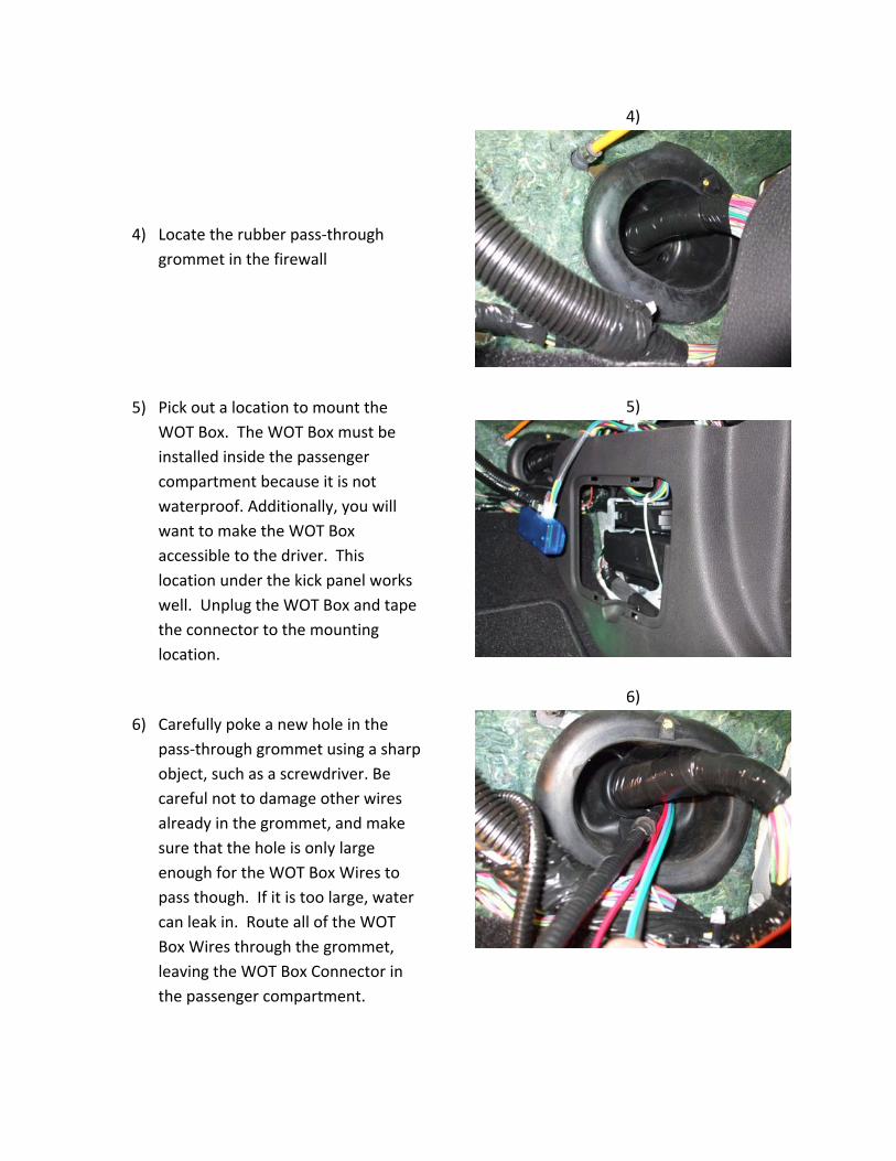
4) Locate the rubber pass‐through grommet in the firewall
5) Pick out a location to mount the WOT Box. The WOT Box must be installed inside the passenger compartment because it is not waterproof. Additionally, you will want to make the WOT Box accessible to the driver. This location under the kick panel works well. Unplug the WOT Box and tape the connector to the mounting location.
6) Carefully poke a new hole in the pass‐through grommet using a sharp object, such as a screwdriver. Be careful not to damage other wires already in the grommet, and make sure that the hole is only large enough for the WOT Box Wires to pass though. If it is too large, water can leak in. Route all of the WOT Box Wires through the grommet, leaving the WOT Box Connector in the passenger compartment.
4)
5)
6)

7) Underneath the battery, there’s a hole that will fit the 7/16” grommet. Install the grommet and route the WOT Box wires through it.
8) Route the WOT Box Wires towards the front of the vehicle along the inside of the fender. Here, a braided loom is used to protect the WOT Box Wires and enhance the aesthetics of the install.
9) The PCM is located in the front of the engine compartment on the passenger side. Unplug all 3 cam‐lock connectors from the PCM by unlocking the grey levers and pulling the connectors out.
7)
8)
9)

10) Determine which connector theGREEN WOT Box Wire goes to foryour car with the pinout chartsabove. Remove enough of the loombehind this connector to access thewires. Splice the GREEN WOT BoxWire into the WHITE wire on the pinindicated on your vehicle’s chart.Use the N2MB recommendedsoldering technique available atwww.n2mb.com.
11) If you haven’t already, removeenough of the loom behind themiddle connector to access thewires. Splice the BLUE WOT BoxWire into the WHITE wire on pin 17of the MIDDLE CONNECTOR. Usethe N2MB recommended solderingtechnique. Re‐install the loom on allconnectors accessed and tapesecurely with electrical tape.
12) Remove enough of the loom behindthe bottom connector to access thewires. Splice the YELLOW WOT BoxWire into the BLACK/PINK wire onpin 47 of the BOTTOM CONNECTOR.Use the N2MB recommendedsoldering technique. Re‐install theloom and tape securely withelectrical tape.
10)
11)
12)

13) The Bussed Electrical Center islocated directly to the passengerside of the PCM. Remove its cover.
14) Remove the 4 bolts in the center ofthe BEC and remove the top of it toallow access to the connectorsunderneath.
15) Remove the backshell on theconnector containing the pin required for the RED & ORANGE WOT Box Pair on your vehicle (see pinout chart.)
13)
14)
15)

16) On the Ignition Coil Power pin foryour vehicle, there are two red wiresfor 8 cylinder vehicles and one for 6cylinder vehicles. Make sure toleave enough room to strip andsplice, and cut this/these wires.
17) Join the RED WOT Box Wire to thewire end/ends coming from theconnector.
18) Join the ORANGE WOT Box Wire ofthe RED & ORANGE Pair to the wire end/ends going back into the harness. Here, the wire appears red on one side, but that’s only the residue from separating the Red & Orange Pair.
19) Replace the Back Backshell and re‐install the connectors into the upperportion of the BEC. Re‐assemble theBEC.
17)
18)
19)

20) Re‐install the 3 cam‐lock connectors.They each will only fit into theirintended socket on the PCM.
21) Near the battery on the suspensiontower, there’s a chassis ground.Route the SINGLE BLACK WOT BoxWire to this location, cut it tolength, strip it, and crimp theincluded eyelet on the bare end.
22) Remove the main ground bolt andensure that the surfaces under thehead of the bolt and on top of thechassis ground eyelet are clean. Ifthey are not, clean them withsandpaper. Slide first the SINGLEBLACK WOT Box Wire eyelet, thenthe chassis ground eyelet onto thebolt, and re‐install the bolt.
20)
22)

23) Reinstall the Fender Liner and Wheel. Ensure that everything that was removed forinstallation has been replaced besides the 12V battery negative. Insert the WOT Boxharness into the WOT Box, reconnect the 12V battery negative, and close the hood.
24) Test the WOT Box as described below, and then re‐install the right passenger side kickpanel.
Troubleshooting ‐ Testing the WOT Box 1. Key on the car but do not start the engine. Press the gas pedal to the floor. You should see
the LED on the WOT Box start to rapidly blink. If it does not, check your APP sensor signal connection (WOT Box BLUE wire).
2. Next, with the gas pedal still depressed, press the clutch pedal to the floor. You should see the LED on the WOT Box briefly go out, and then come back on solid for one second and then finally resume blinking rapidly. If you do not see this, check your Clutch Pedal Position Switch signal connection (WOT Box GREEN wire).
3. Next, start the engine. Quickly press the gas pedal to the floor and immediately step on the clutch. You should hear the engine start to rev up, stumble for a short period while the ignition is cut, then return back on and continue revving. Remove your foot from the gas before you hit the rev limiter. The 2‐step will not engage if the gas is depressed before the clutch. This is normal. If the engine does not stumble or pause when the LED turns out, then check the RED/ORANGE paired wire. Verify that the RED and ORANGE 16 AWG wires are wired facing the proper way. If they are reversed, the ignition cut will not work.
4. Lastly, test the 2‐Step. Press the clutch pedal down and then quickly press the gas pedal all the way down. The gas pedal must be floored for the 2‐step to engage. The engine should rev up to the desired RPM and hold. If it does not, be sure to remove your foot from the gas before you hit the rev limiter. If the 2‐step does not work, check the WOT Box YELLOW wire.
5. The WOT Box Graphical User Interface has some inherent troubleshooting capability. If you have access to a laptop, it may be useful for you to download the GUI atwww.n2mb.com/wotboxsoftware and follow the instructions there.
Usage
To use the WOT Shift feature, keep your foot fully on the gas and shift quickly using the clutch. Keep the gas fully depressed through the shift. The WOT Box will detect the clutch switch signal and briefly cut the ignition to enable an effortless shift.
To use the 2‐Step feature, fully depress the clutch. Next, fully depress the gas pedal to the floor. The engine will rev up and hold the RPM that you have set. Quickly release the clutch while leaving the gas fully depressed to launch the car.
CONGRATULATIONS!
You have successfully installed the N2MB WOT BOX!
N2MB Racing Limited Warranty N2MB Racing warrants that all of its products are free from defects in material and workmanship for a period of 1 year from the date of purchase. If an N2MB product is found to be defective within this period, N2MB Racing will repair or replace the product. The choice between these two methods of remedy is made at the sole discretion of N2MB Racing. This shall constitute the sole remedy of the purchaser and the sole liability of N2MB Racing to the extent permitted by law. This warranty is exclusive and in lieu of all other warranties or representations whether expressed or implied. This warranty is limited to the repair or replacement of the N2MB Racing product, and shall never exceed the purchase price of the N2MB Racing product. N2MB shall not be responsible for special or consequential damage or costs incurred as a result of the failure or use of the N2MB Racing Product except as required by law. Unauthorized alteration or repair of N2MB Racing products will void this warranty if the alteration or repair is found to have caused the N2MB Racing product to fail. In the event that a product is warranted, the purchaser shall be responsible for any and all shipping costs.
N2MB Racing reserves the right to improve its products at any time and is at no time responsible for exchange or upgrade of products that were manufactured previously.