
v2512 | v2012 | v2640 | v1840 UHS MANUAL
47
ULTRAHIGH-SPEED CAMERAS v2512 | v2012 | v2640 | v1840 UHS MANUAL When it’s too fast to see, and too important not to. ®
Transcript of v2512 | v2012 | v2640 | v1840 UHS MANUAL

ULTRAHIGH-SPEED CAMERASv2512 | v2012 | v2640 | v1840
UHS MANUAL
When it’s too fast to see, and too important not to.®

PN: ZDOC-64110-MA-0001 Rev 5Last Updated: July 2021
WWW.PHANTOMHIGHSPEED.COM
Phantom Ultrahigh-Speed Cameras
MANUAL
100 Dey RoadWayne, NJ 07470 USA+1.973.696.4500
When it’s too fast to see, and too important not to.®

Written and produced by the Marketing Department at Vision Research.
The contents of this manual are subject to change without notification.
1 Camera Overview 1
2 Connectors 5
3 Network Setup & Quick Start Guides 7
4 On-Camera Controls & On-Screen Displays 15
5 Working with Phantom CineMags 27
6 Phantom PCC Software: Camera Operation, Download and File Conversion 33
7 Programmable I/O Signal Architecture 45
8 Measurements with PCC 51
9 Accessories 59
10 FAQs & Support 63PN: ZDOC-64110-MA-0001 Rev 5Last Updated: July 2021
P H A N T O M H I G H S P E E D . C O M

v2512 v2012Max. Resolution 1280 x 800
Fps at Max. Res 25,700 22,600
Fps at Reduced Resolution
1,000,000 at 256x32 with FAST option (663,250 w/o)
1,000,000 at 128x32 with FAST option (651,150 w/o)
Minimum Fps 100
CAR 128 x 16
Sensor Size 35.8 mm x 22.4 mm
Pixel Pitch 28 µm size, 12-bit depth
Min. Exposure1 µs (standard)
265 ns with FAST option
1 µs (standard) 290 ns
with FAST option
Straddle Time 375 ns 400 ns
Native ISO (122232 SAT Method)
Monochrome: 32,000D Color: 6,400D
Adjustable Exposure Index (EI)
Mono: 32,000–160,000Color: 6,400–32,000
Memory 72GB, 144GB, 288GB high-speed internal RAM CineMag IV (1TB or 2TB), CineMag V (2TB or 8TB) non-volatile memory storage
Power 20–28VDC, 280 watt power supply included
Size & Weight 17 lbs, 8 oz. (8.1 Kg) (without lens)
Operational Temperature
Operating Temperature: -10 to +50°C10Gb Ethernet Operation: +5 to +50°C
CineMag V Run/Stop Operation: -10 to +40°CStorage Temperature: -20 to +70°C
Humidity: 95% non-condensing
Shock Rating Operational: 5.5 G, 11mSec sawtooth, 3 axes, 60 pulses totalNon-Operational: 30 G, 11mSec sawtooth, 3 axes, 60 pulses total
Ethernet Standard Gb Ethernet and 10Gb Ethernet (standard)
Video Two HD-SDI ports on camera; Analog video (NTSC or PAL), available on Break-out-Box; Component viewfinder port
On-Camera Controls (OCC) Full OCC menu plus B-Ref, Tools, Playback and Trigger buttons
Programmable I/O
4 ports; define parameters of F-Sync, Strobe, Event, Pre-trigger, Memgate, Timecode-out, Ready, Aux, Auto-trigger
Special Features
SYNC-to-Trigger, Image-Based Auto-Trigger, Burst Mode, PIV Exposure, Continuous Recording, Multi-Cine with memory partitioning, Quiet Fans
v2640 / v1840Standard Mode
(CDS)Standard Binned HS Mode HS Bright
Field Mode HS Binned
Max. Resolution 2048 x 1952 1024 x 976 2048 x 1952 2048 x 1944 1024 x 976
Fps at Max. Res 4,855 / 3,320 18,390 / 12,670 6,600 / 4,510 6,600 / 4,510 25,030 / 17,240
Read Out Noise (e-) 7.2 11.9 18.8 58 29.7
Dynamic Range (dB) (Typical) 64 66.2 56.7 59.8 58.5
CAR 128 x 8 128 x 16 128 x 8 128 x 8 128 x 16
Sensor Size 27.6 mm x 26.3 mm
Pixel Pitch 13.5 µm size, 12-bit depth
Min. Exposure 1 µs (standard), 499 ns with FAST option 1 µs (standard), 142 ns with FAST option
Straddle Time 490 ns 696 ns
Native ISO (122232 SAT Method)
Mono: 16,000DColor: 3,200D
Mono: 25,000DColor: 5,000D
Mono: 12,500DColor: 3,200D
Mono: 2,500DColor: 500D
Mono: 25,000DColor: 5,000D
Adjustable Exposure Index (EI)
Mono: 16,000–80,000
Color: 3,200–16,000
Mono: 25,000–125,000
Color: 5,000–25,000
Mono: 12,500–62,500
Color: 3,200–16,000
Mono: 2,500–12,500
Color: 500–2,500
Mono: 25,000–125,000
Color: 5,000–25,000
Memory 72GB, 144GB, 288GB high-speed internal RAM CineMag IV (1TB or 2TB), CineMag V (2TB or 8TB) non-volatile memory storage
Power 20–28VDC, 280 watt power supply included
Size & Weight 17 lbs, 8 oz. (8.1 Kg) (without lens)
Operational Temperature
Operating Temperature: -10 to +50°C10Gb Ethernet Operation: +5 to +50°C
CineMag V Run/Stop Operation: -10 to +40°CStorage Temperature: -20 to +70°C
Humidity: 95% non-condensing
Shock Rating Operational: 5.5 G, 11mSec sawtooth, 3 axes, 60 pulses totalNon-Operational: 30 G, 11mSec sawtooth, 3 axes, 60 pulses total
Ethernet Standard Gb Ethernet and 10Gb Ethernet (standard)
Video Two HD-SDI ports on camera; Analog video (NTSC or PAL), available on Break-out-Box; Component viewfinder port
On-Camera Controls (OCC) Full OCC menu plus B-Ref, Tools, Playback and Trigger buttons
Programmable I/O
4 ports; define parameters of F-Sync, Strobe, Event, Pre-trigger, Memgate, Timecode-out, Ready, Aux, Auto-trigger
Special Features
Correlated Double Sampling (CDS), SYNC-to-Trigger, Image-Based Auto-Trigger, Burst Mode, PIV Exposure, Continuous Recording, Multi-Cine with memory partitioning, Quiet Fans
SP
EC
IFIC
AT
ION
S

Vision Research, Inc. | Phantom Ultrahigh-Speed Camera Manual Chapter 1: Camera Over view | 1
CA
MER
A O
VER
VIE
W
INTRODUCTION The Phantom Ultrahigh-Speed (UHS) Series consists of 1 Megapixel (Mpx) and 4 Mpx cameras.
The 1 Mpx members are the v2012 and v2512. With throughputs up to 25 Gigapixels per second (Gpx/sec), these cameras are designed for very high frame rate applications. They use a proprietary CMOS sensor and have the very high light sensitivity needed for high-speed applications.
High throughput is important. At any given resolution, a camera with the highest throughput provides the highest possible frame rates.
The 4 Mpx members are the v1840 and v2640. They are designed to provide exceptional image detail and quality coupled with high throughput. They also use a proprietary CMOS sensor that offers flexibility with standard Correlated Double Sampling (CDS) mode, High Speed, Bright Field and Binned modes that can be switched in software.
All Phantom Ultrahigh-Speed cameras have global electronic shutters.
OPERATING MODES (v1840 / v2640)The v1840 and v2640 can operate in five different modes, selectable in PCC.
Standard Mode: Standard mode implements Correlated Double Sampling (CDS), providing the highest dynamic range and lowest noise.
High Speed (HS) Mode: HS mode does not incorporate CDS, but instead provides up to 34 percent increase in throughput.

Vision Research, Inc. | Phantom Ultrahigh-Speed Camera Manual Chapter 1: Camera Over view | 3
Binning: Binning groups four pixels in a square to create one large pixel. This effectively converts the 4 Mpx sensor with a maximum resolution of 2048 x 1952 pixels to a 1 Mpx sensor with a 1024 x 976 maximum resolution consisting of very large 27 micron (µm) pixels. Both monochrome and color cameras have Binning, however the image output is monochrome.
Binning is available in two modes, Standard (with CDS) and High Speed (HS).
Bright Field Mode: Bright Field mode is applied on the HS mode. It is specially engineered with a much larger full well, increasing the maximum Signal-to-Noise Ratio (SNR). This mode is ideal for clean images in bright to very bright backgrounds.
SENSITIVITY & EXPOSURE INDEXAll UHS cameras are available in monochrome or color versions and have the Exposure Index (EI) function. Using EI adjusts the tone curves in software without affecting the native data. It has eight selections to brighten the image by increasing the camera’s effective ISO.
The UHS-12 cameras have 28 µm pixels, resulting in very high light sensitivity. The UHS-40 cameras have 13.5 µm pixels, converting to 27 µm pixels and offering higher sensitivity in Binned mode. Sensitivity and ISO ratings for all Phantom cameras are measured in accordance with the ISO 12232 SAT method.
CAMERA CONTROLAll Phantom cameras come with PCC software for Ethernet-based setup and control. The Phantom Ultrahigh-Speed cameras also have an On-Camera Control (OCC) menu system for use with an attached video monitor. The OCC menu can adjust both basic and advanced settings. Capture, Play and Save-to-CineMag functions are also available via the camera’s OCC menu.
IMAGE STORAGEThe Phantom Ultrahigh-Speed cameras can be equipped with 72GB, 144GB or 288GB of high-speed memory. A camera with 288GB of memory, recording at 10,000 fps at 1280 x 800 can record a single high-speed shot (called a Cine) for almost 20 seconds.
All Phantom Ultrahigh-Speed Series cameras are also compatible with Phantom CineMag IV and V long recording non-volatile memory. CineMag V is available in 2TB and 8TB capacities, and can accurately save a 288GB Cine to an attached Phantom CineMag V in about 4.5 minutes.
Data on a CineMag can be downloaded via a Phantom CineStation IV, or the camera, using 1Gb or 10Gb Ethernet. The 10Gb Ethernet transfers data at up to 600 MB/second on optimized systems.
Cine Raw files are compatible with many of the video industry’s top editing programs, or they can be converted to a variety of formats (h264.mp4, Apple ProRes.mov, avi, tiff, etc.) using PCC software with the camera.
IMAGE MONITORING & VIDEO OUTPUTSPhantom UHS camera models have two 1.5G HD-SDI outputs on the rear of the camera and a component video/12V power viewfinder output on the side of the camera. The systems supported are: 720p at 50, 59.9, 60 Hz, 1080p (also psf and i) at 23.9, 24, 25, 29.9, 30. These make it easy to use a small on-camera monitor or viewfinder for composing the shot and watching a smooth playback without being tethered to a computer.
The feed from the video outputs are identical and can show either live video or playback.
ADDITIONAL FEATURESProgrammable I/O: Assign and define signal parameters. See Programmable I/O Signal Architecture section for more information.
Image-Based Auto-Trigger (IBAT): Trigger the camera (or a number of connected cameras) from motion detected within the live image.
Multi-Cine: Support for up to 63 partitions.
Burst Mode: Generate a precise number of frames with every frame sync pulse.
Quiet Fans: Turns the fans off to eliminate vibration.
Continuous Recording: Automatically and continuously saves Cines to external storage.
10Gb Ethernet: 10GBase-T (RJ45) Ethernet port for very fast data transfer.
Exposure in PIV Mode: Also known as Shutter Off Mode, Exposure in PIV turns off the shutter to maximize achievable exposure with minimal frame overhead.
P12L: The P12L feature is for situations where 12 linear bits of an image need to be downloaded. For most situations, the standard 10-bit packed method is sufficient, has no visible data loss and is significantly faster to download.
DHCP: Dynamic Host Configuration Protocol is a network protocol enabling the automatic assignment of IP addresses when using a DHCP router.

Vision Research, Inc. | Phantom Ultrahigh-Speed Camera Manual Chapter 2: Connectors | 5
CO
NN
ECTO
RS
A
B
C
D
E
F
G
K
I
M
P
H
L
O
J
N
Q
TRIGGER
TIME CODE IN
FSYNC /P
READY /P
STROBE /P
TC OUT /P
POWER SWITCH
1Gb ETHERNET
10Gb ETHERNET
PRIMARY DC INPUT
BACKUP DC POWER
CAPTURE PORT
REMOTE CONTROL PORT
RANGE DATA
GPS
HD-SDI 2 HD-SDI 1
TTL Pulse (Rising/Falling Edge), Switch Closure
IRIG-B In (Modulated/Unmodulated)
Programmable I/O (Default: F-Sync)
Programmable I/O (Default: Ready)
Programmable I/O (Default: Strobe)
Programmable I/O (Default: Time Code Out: (IRIG-B)
Off / Auto / On
CAT5 UTP (for control and data transfer)
RJ45 10GBase-T UTP (for control and data transfer)
20-28 Volts DC
20-28 Volts DC Backup
Ready, Strobe, A-Sync, Pre-trigger, NTSC/PAL, Video
RS-232 and Power (for Phantom Remote Control)
Used to stamp images with acquisition data (azimuth and elevation)
GPS input for GPS timing, longitude and latitude
The two HD-SDI ports can act as identical 4:2:2 HD-SDI ports with one set up to provide an on-screen display to monitor the on-camera controls and camera operation
Assign and define Programmable I/O ports using PCC. Instructions can be found in the Programmable I/O section of this manual.
A complete cable connector reference and pin-out guide is available in the last section of this manual.
View of Phantom UHS-12 and UHS-40 rear connector panel.
REAR CONNECTOR PANEL

Vision Research, Inc. | Phantom Ultrahigh-Speed Camera Manual Chapter 3: Network Setup & Quick Start Guides | 7
NET
WO
RK
SET
UP
&
QU
ICK
STA
RT
GU
IDES
SIDE CONNECTORVF PWR OR COMPONENT VF
7-pin Fischer provides +12V power and component signal for viewfinders. Also works with the Phantom YPRPB cable.
Phantom cameras are typically controlled with PCC software through a dedicated Ethernet network. PCC is compatible with the 32- and 64-bit versions of Windows 8 and 10 operating systems.
The latest version can be downloaded at: www.phantomhighspeed.com/PCC
1Gb & 10Gb ETHERNETAll Phantom UHS cameras come with standard Gigabit (Gb) Ethernet and 10-Gigabit (10Gb) Ethernet for use as a secondary means of connection. With 10Gb Ethernet, the Phantom UHS cameras can achieve significantly higher download speeds, which makes them a great option for saving large files quickly out of RAM.
The Gb Ethernet and 10Gb Ethernet have separate ports and different IP configurations, as described later in this section.
The ‘IP’ and ‘XIP’ addresses assigned to the camera (that begin with 100.100 and 172.16 respectively) can be found on the Serial Number and IP Address label.
Vision Research, Inc. | Phantom Ultrahigh-Speed Camera Manual Chapter 3: Network Setup & Quick Start Guides | 9
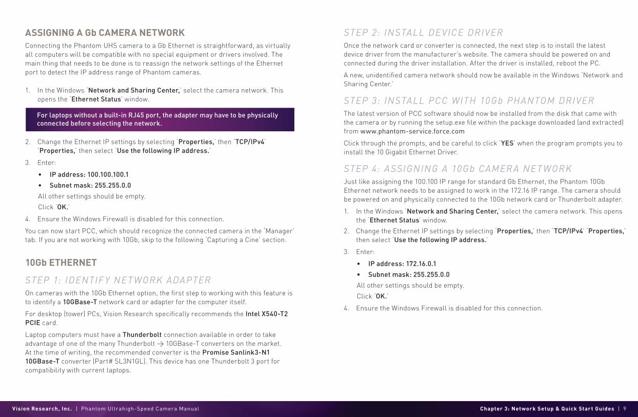
ASSIGNING A Gb CAMERA NETWORK
Connecting the Phantom UHS camera to a Gb Ethernet is straightforward, as virtually all computers will be compatible with no special equipment or drivers involved. The main thing that needs to be done is to reassign the network settings of the Ethernet port to detect the IP address range of Phantom cameras.
1. In the Windows ‘Network and Sharing Center,’ select the camera network. This opens the ‘Ethernet Status’ window.
2. Change the Ethernet IP settings by selecting ‘Properties,’ then ‘TCP/IPv4’ ‘Properties,’ then select ‘Use the following IP address.’
3. Enter:
• IP address: 100.100.100.1
• Subnet mask: 255.255.0.0
All other settings should be empty.
Click ‘OK.’
4. Ensure the Windows Firewall is disabled for this connection.
You can now start PCC, which should recognize the connected camera in the ‘Manager’ tab. If you are not working with 10Gb, skip to the following ‘Capturing a Cine’ section.
10Gb ETHERNET
STEP 1: IDENTIF Y NET WORK ADAPTER
On cameras with the 10Gb Ethernet option, the first step to working with this feature is to identify a 10GBase-T network card or adapter for the computer itself.
For desktop (tower) PCs, Vision Research specifically recommends the Intel X540-T2 PCIE card.
Laptop computers must have a Thunderbolt connection available in order to take advantage of one of the many Thunderbolt > 10GBase-T converters on the market. At the time of writing, the recommended converter is the Promise Sanlink3-N1 10GBase-T converter (Part# SL3N1GL). This device has one Thunderbolt 3 port for compatibility with current laptops.
STEP 2: INSTALL DEVICE DRIVEROnce the network card or converter is connected, the next step is to install the latest device driver from the manufacturer’s website. The camera should be powered on and connected during the driver installation. After the driver is installed, reboot the PC.
A new, unidentified camera network should now be available in the Windows ‘Network and Sharing Center.’
STEP 3: INSTALL PCC WITH 10Gb PHANTOM DRIVERThe latest version of PCC software should now be installed from the disk that came with the camera or by running the setup.exe file within the package downloaded (and extracted) from www.phantom-service.force.com
Click through the prompts, and be careful to click ‘YES’ when the program prompts you to install the 10 Gigabit Ethernet Driver.
STEP 4: ASSIGNING A 10Gb CAMERA NET WORKJust like assigning the 100.100 IP range for standard Gb Ethernet, the Phantom 10Gb Ethernet network needs to be assigned to work in the 172.16 IP range. The camera should be powered on and physically connected to the 10Gb network card or Thunderbolt adapter.
1. In the Windows ‘Network and Sharing Center,’ select the camera network. This opens the ‘Ethernet Status’ window.
2. Change the Ethernet IP settings by selecting ‘Properties,’ then ‘TCP/IPv4’ ‘Properties,’ then select ‘Use the following IP address.’
3. Enter:
• IP address: 172.16.0.1
• Subnet mask: 255.255.0.0
All other settings should be empty.
Click ‘OK.’
4. Ensure the Windows Firewall is disabled for this connection.
For laptops without a built-in RJ45 port, the adapter may have to be physically connected before selecting the network.
Vision Research, Inc. | Phantom Ultrahigh-Speed Camera Manual Chapter 3: Network Setup & Quick Start Guides | 11
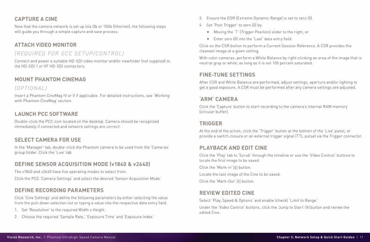
CAPTURE A CINENow that the camera network is set up (via Gb or 10Gb Ethernet), the following steps will guide you through a simple capture and save process.
ATTACH VIDEO MONITOR
(REQUIRED FOR OCC SETUP/CONTROL)Connect and power a suitable HD-SDI video monitor and/or viewfinder (not supplied) to the HD-SDI 1 or VF HD-SDI connectors.
MOUNT PHANTOM CINEMAG
(OPTIONAL)Insert a Phantom CineMag IV or V if applicable. For detailed instructions, see ‘Working with Phantom CineMag’ section.
LAUNCH PCC SOFTWAREDouble-click the PCC icon located on the desktop. Camera should be recognized immediately if connected and network settings are correct.
SELECT CAMERA FOR USEIn the ‘Manager’ tab, double-click the Phantom camera to be used from the ‘Cameras’ group folder. Click the ‘Live’ tab.
DEFINE SENSOR ACQUISITION MODE (v1840 & v2640)The v1840 and v2640 have five operating modes to select from.
Click the PCC ‘Camera Settings’ and select the desired ‘Sensor Acquisition Mode.’
DEFINE RECORDING PARAMETERSClick ‘Cine Settings’ and define the following parameters by either selecting the value from the pull-down selection list or typing a value into the respective data entry field.
1. Set ‘Resolution’ to the required Width x Height.
2. Choose the required ‘Sample Rate,’ ‘Exposure Time’ and ‘Exposure Index.’
3. Ensure the EDR (Extreme Dynamic Range) is set to zero (0).
4. Set ‘Post Trigger’ to zero (0) by:
• Moving the ‘T’ (Trigger Position) slider to the right, or
• Enter zero (0) into the ‘Last’ data entry field.
Click on the CSR button to perform a Current Session Reference. A CSR provides the cleanest image at a given setting.
With color cameras, perform a White Balance by right-clicking an area of the image that is neutral gray or white, as long as it is not 100 percent saturated.
FINE-TUNE SETTINGSAfter CSR and White Balance are performed, adjust settings, aperture and/or lighting to get a good exposure. A CSR must be performed after any camera settings are adjusted.
‘ARM’ CAMERAClick the ‘Capture’ button to start recording to the camera’s internal RAM memory (circular buffer).
TRIGGERAt the end of the action, click the ‘Trigger’ button at the bottom of the ‘Live’ panel, or provide a switch closure or an external trigger signal (TTL pulse) via the Trigger connector.
PLAYBACK AND EDIT CINEClick the ‘Play’ tab to ‘Scrub’ through the timeline or use the ‘Video Control’ buttons to locate the first image to be saved.
Click the ‘Mark-in’ button.
Locate the last image of the Cine to be saved.
Click the ‘Mark-Out’ button.
REVIEW EDITED CINESelect ‘Play, Speed & Options’ and enable (check) ‘Limit to Range.’
Under the ‘Video Control’ buttons, click the ‘Jump to Start’ button and review the edited Cine.
Vision Research, Inc. | Phantom Ultrahigh-Speed Camera Manual Chapter 3: Network Setup & Quick Start Guides | 13
SAVE TO COMPUTERClick the large ‘Save Cine...’ button on the bottom of the ‘Play’ panel.
In the ‘Save Cine’ window:
1. Navigate to the folder where you want to save the Cine file.
2. Enter a file name for the Cine file in the ‘File name:’ data entry field.
3. From the ‘Save as Type’ pull-down selection list, select the ‘Cine Raw, *.cine’ file format.
4. Click the ‘Save’ button to begin downloading the Cine file from the camera.
Confirm that the Cine is saved before deleting from internal memory.
CONFIRM COMPUTER SAVEClick the ‘Open File’ button.
Navigate to the folder and open the saved Cine file. Review the playback by scrubbing through the file and viewing the playback.
SAVE TO CINEMAG IV/V
(OPTIONAL)Click the down-arrow of the ‘Save Cine...’ button.
Select ‘Save RAM Cine to Flash’ (in pop-up window).
Click the ‘Save’ button to save the Cine file onto the Phantom CineMag.
Confirm ‘Flash Cine Save’ before deleting from internal memory.
CONFIRM CINEMAG SAVESelect the new Flash Cine from the top ‘Play / Cine’ pull-down list or via the ‘Manager’ tab. Double-click the ‘Cine F#’ file under the camera used to record the Cine.
Scrub through Cine file to review.
Vision Research, Inc. | Phantom Ultrahigh-Speed Camera Manual Chapter 4: On-Camera Controls & On-Screen Displays | 15
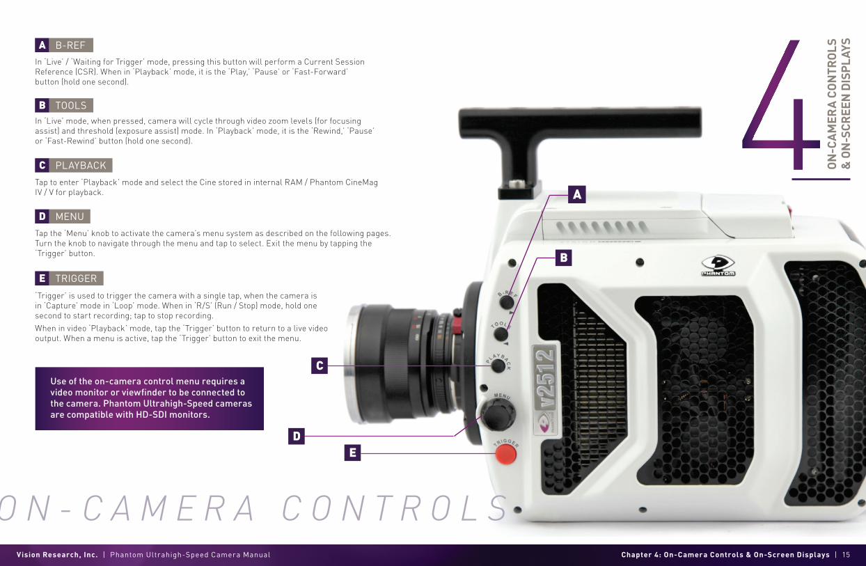
Tap the ‘Menu’ knob to activate the camera’s menu system as described on the following pages. Turn the knob to navigate through the menu and tap to select. Exit the menu by tapping the ‘Trigger’ button.
‘Trigger’ is used to trigger the camera with a single tap, when the camera is in ‘Capture’ mode in ‘Loop’ mode. When in ‘R/S’ (Run / Stop) mode, hold one second to start recording; tap to stop recording.
When in video ‘Playback’ mode, tap the ‘Trigger’ button to return to a live video output. When a menu is active, tap the ‘Trigger’ button to exit the menu.
Tap to enter ‘Playback’ mode and select the Cine stored in internal RAM / Phantom CineMag IV / V for playback.
In ‘Live’ mode, when pressed, camera will cycle through video zoom levels (for focusing assist) and threshold (exposure assist) mode. In ‘Playback’ mode, it is the ‘Rewind,’ ‘Pause’ or ‘Fast-Rewind’ button (hold one second).
In ‘Live’ / ‘Waiting for Trigger’ mode, pressing this button will perform a Current Session Reference (CSR). When in ‘Playback’ mode, it is the ‘Play,’ ‘Pause’ or ‘Fast-Forward’ button (hold one second).
ON
-CA
MER
A C
ON
TRO
LS
& O
N-S
CREE
N D
ISP
LAYS
Use of the on-camera control menu requires a video monitor or viewfinder to be connected to the camera. Phantom Ultrahigh-Speed cameras are compatible with HD-SDI monitors.
A
B
C
D
E
B-REF
TOOLS
PLAYBACK
TRIGGER
MENU
O N - C A M E R A C O N T R O L S

Vision Research, Inc. | Phantom Ultrahigh-Speed Camera Manual Chapter 4: On-Camera Controls & On-Screen Displays | 17
B
C
D
E
F
G
K
I
H
L
J
TIMECODE
BUFFER BAR WITH TRIGGER POINT
FLASH MEMORY STATUS
FRAME COUNT & DURATION
EF LENS APERTURE DATA
CINE INDICATOR
PLAYBACK
PLAYBACK BAR
PLAYBACK TIMECODE
CAMERA NAME
CAPTURE SETTINGS
ON-SCREEN DISPLAY (OSD) OVERVIEW The On-Screen Display (OSD) provides valuable information about the camera’s current status over the video outputs along with the live or playback images.
Frame count and playback duration based on current video settings, within the mark-in and mark-out points.
Indicates the IRIG timecode stamped to each frame.
This ‘timeline’ represents all frames available in camera RAM (‘Loop’ mode). The ‘T’ indicator represents the user-defined trigger point.
Displays the frame count and recording time based on the current camera settings.
Indicates the memory size of the Phantom CineMag (if present) and the total recording time available.
Displays the f-stop (aperture) the lens. Valid for Canon EF mounts only.
Indicates user-defined camera name. If not defined, the camera serial number is displayed.
Shows frame rate, exposure time and resolution.
Indicates the Cine number selected for playback.
A visual representation of the Cine timeline with the trigger (T) point, mark-in and mark-out (|) points, and play head indicated.
Shows the timestamp of each frame in IRIG format and the current frame number.
VIDEO DISPL AY, ‘LIVE’ MODE
VIDEO DISPL AY, ‘PL AYBACK’ MODE
A CAMERA STATEThe symbol changes based on the camera’s state:
Live: The camera is not recording and a live image is displayed from all SDI ports.
Capture: The camera is recording to internal memory (RAM) and awaiting a trigger signal.
Triggered: The camera has been triggered and is filling RAM memory (‘Post-Trigger’ frames).
Cine Stored: Recording has ended and a Cine is stored in RAM memory. The Cine must be erased from the RAM to begin recording again.
Playback: The camera is in ‘Playback’ mode. RAM Cines can be reviewed, edited and saved to flash.

Vision Research, Inc. | Phantom Ultrahigh-Speed Camera Manual Chapter 4: On-Camera Controls & On-Screen Displays | 19
1/6 CAMERAThe CAMERA menu page includes controls for the fundamental settings.
SPEED Sets the acquisition frame rate in frames-per-second.
SHUT TERSets the exposure time.
EISets the Exposure Index (EI).
AUTOE XPOSUREEnables autoexposure for changing lighting conditions.
WHITE BAL ANCEFor color cameras, place a white or neutral gray object in front of the camera. Ensure that the white subject is not fully saturated. Select the phrase ‘White Balance’ and rotate to select ‘OK.’
RESOLUTIONSets the acquisition resolution of the sensor.
TRIGGERSets the trigger point. The timeline represents all frames available in RAM.
SYNCChanges the frame sync (F-Sync) from internal to an external source.
AUTO B-REFWhen enabled, a black reference will be automatically performed when the camera enters ‘Capture’ mode.
MENU OVERVIEWThe Phantom Ultrahigh-Speed On-Camera Control menus provide access to almost all camera settings. The menu is activated with a press of the menu knob and displayed through the camera’s video outputs (SDI) as a video overlay, on top of the live image.
NAVIGATIONActivate the menu by pressing the ‘Menu’ knob on the side of the camera. Turn the knob to scroll through each menu item and press to select. The six menu pages can be quickly jumped between by selecting the page title (‘1/6 CAMERA’ in this example) and scrolling through them.
To exit the menu, tap the ‘Trigger’ button. The menu will also turn itself off after a period of inactivity.
The menu is subject to change as functionality may be added with future firmware updates.
M E N U S Y S T E M
SIX MENU PAGES1/6 CAMERA2/6 IMAGE3/6 SETTINGS4/6 INFO5/6 AUTO6/6 ADVANCED
Vision Research, Inc. | Phantom Ultrahigh-Speed Camera Manual Chapter 4: On-Camera Controls & On-Screen Displays | 21
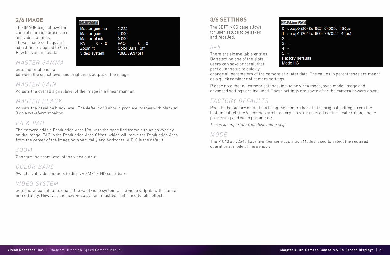
3/6 SETTINGSThe SETTINGS page allows for user setups to be saved and recalled.
0 –5 There are six available entries. By selecting one of the slots, users can save or recall that particular setup to quickly change all parameters of the camera at a later date. The values in parentheses are meant as a quick reminder of camera settings.
Please note that all camera settings, including video mode, sync mode, image and advanced settings are included. These settings are saved after the camera powers down.
FACTORY DEFAULTSRecalls the factory defaults to bring the camera back to the original settings from the last time it left the Vision Research factory. This includes all capture, calibration, image processing and video parameters.
This is an important troubleshooting step.
MODEThe v1840 ad v2640 have five ‘Sensor Acquisition Modes’ used to select the required operational mode of the sensor.
2/6 IMAGEThe IMAGE page allows for control of image processing and video settings. These image settings are adjustments applied to Cine Raw files as metadata.
MASTER GAMMA Sets the relationship between the signal level and brightness output of the image.
MASTER GAINAdjusts the overall signal level of the image in a linear manner.
MASTER BL ACKAdjusts the baseline black level. The default of 0 should produce images with black at 0 on a waveform monitor.
PA & PAOThe camera adds a Production Area (PA) with the specified frame size as an overlay on the image. PAO is the Production Area Offset, which will move the Production Area from the center of the image both vertically and horizontally. 0, 0 is the default.
ZOOMChanges the zoom level of the video output.
COLOR BARSSwitches all video outputs to display SMPTE HD color bars.
VIDEO SYSTEMSets the video output to one of the valid video systems. The video outputs will change immediately. However, the new video system must be confirmed to take effect.
Vision Research, Inc. | Phantom Ultrahigh-Speed Camera Manual Chapter 4: On-Camera Controls & On-Screen Displays | 23
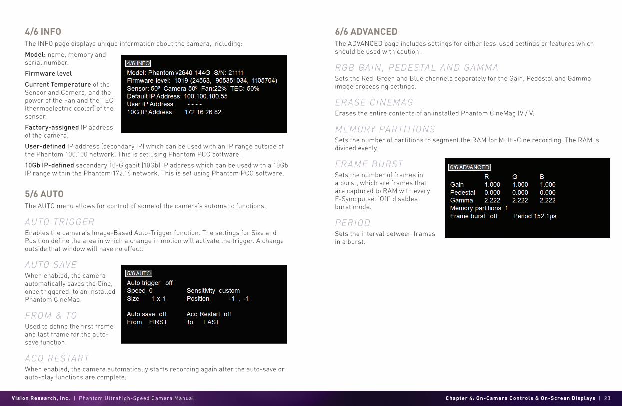
6/6 ADVANCEDThe ADVANCED page includes settings for either less-used settings or features which should be used with caution.
RGB GAIN, PEDESTAL AND GAMMA Sets the Red, Green and Blue channels separately for the Gain, Pedestal and Gamma image processing settings.
ERASE CINEMAGErases the entire contents of an installed Phantom CineMag IV / V.
MEMORY PARTITIONSSets the number of partitions to segment the RAM for Multi-Cine recording. The RAM is divided evenly.
FRAME BURSTSets the number of frames in a burst, which are frames that are captured to RAM with every F-Sync pulse. ‘Off’ disables burst mode.
PERIODSets the interval between frames in a burst.
5/6 AUTOThe AUTO menu allows for control of some of the camera’s automatic functions.
AUTO TRIGGEREnables the camera’s Image-Based Auto-Trigger function. The settings for Size and Position define the area in which a change in motion will activate the trigger. A change outside that window will have no effect.
AUTO SAVEWhen enabled, the camera automatically saves the Cine, once triggered, to an installed Phantom CineMag.
FROM & TOUsed to define the first frame and last frame for the auto-save function.
ACQ RESTARTWhen enabled, the camera automatically starts recording again after the auto-save or auto-play functions are complete.
4/6 INFOThe INFO page displays unique information about the camera, including:
Model: name, memory and serial number.
Firmware level
Current Temperature of the Sensor and Camera, and the power of the Fan and the TEC (thermoelectric cooler) of the sensor.
Factory-assigned IP address of the camera.
User-defined IP address (secondary IP) which can be used with an IP range outside of the Phantom 100.100 network. This is set using Phantom PCC software.
10Gb IP-defined secondary 10-Gigabit (10Gb) IP address which can be used with a 10Gb IP range within the Phantom 172.16 network. This is set using Phantom PCC software.

Vision Research, Inc. | Phantom Ultrahigh-Speed Camera Manual Chapter 4: On-Camera Controls & On-Screen Displays | 25
CAPTURE A CINECapture a Cine file to RAM:
Ensure camera is in ‘Capture’ mode.
Tap the ‘Trigger’ button to trigger the camera once the event happens.
With Cine in RAM, tap the ‘Playback’ button. The video output will switch to playback view, where you must select the Cine for playback. In the case of Multi-Cine (partitioned) RAM, there will be more than one RAM Cine present.
Once the take is selected, there are options to ‘Play,’ ‘Delete,’ ‘Delete All’ or ‘Go Back.’ Selecting ‘Play’ will close the menu and the video will begin to play forward.
Use the ‘Play Forward’ and ‘Play Backwards’ buttons and the menu knob to scrub through the Cine. A long press on the forward or reverse buttons will start a fast-forward and fast-reverse playback.
EDIT THE CINETap the menu knob to further edit and save the Cine to an installed CineMag IV / V. An action menu appears with more options.
Use the scroll knob to go through the Cine.
Set the in-point by selecting ‘Set In.’ This will be the first frame of the Cine saved to the installed Phantom CineMag. Scroll to the last frame you want to save and select ‘Set Out.’
SAVE THE CINE Select ‘Save’ to save the Cine to the Phantom CineMag. The OSD will report that the Phantom CineMag is saving and providing a countdown. Do not interrupt this saving process.
Once saved, the RAM can be cleared and the camera can go back into ‘Capture’ mode. The fastest way to do this is to hold down the ‘Trigger’ button for four seconds.
P L A Y B A C K & S A V E

Vision Research, Inc. | Phantom Ultrahigh-Speed Camera Manual Chapter 5: Working with Phantom CineMags | 27
PHANTOM CINEMAG IV & V INDICATORSOn the back of the Phantom CineMag are a number of LED indicators that show the current Phantom CineMag status.
P H A N T O M C I N E M A G I V / V
MAG CAPACIT Y INDICATORWhen a Phantom CineMag is empty, all lights will be illuminated. As material is recorded to the mag, the lights will turn off. The last light will always stay on to indicate power.
ERASE PROTECT SWITCHWhen the erase protect switch is in the lock position, the CineMag cannot be erased. Use an appropriate tool, such as a micro-flathead screwdriver, to flip the switch. ACTIVIT Y LED
Green for read activityRed indicates recordingOrange indicates erasing
WO
RK
ING
WIT
H
PHA
NTO
M C
INEM
AGS
INTRODUCTION The Phantom UHS-12 and UHS-40 cameras offer a CineMag compatibility option. Cameras that have CineMag compatibility may use either a CineMag IV or CineMag V. Only UHS-11 and UHS-10 cameras are compatible with CineMag II.
The Phantom CineMag is a high-speed solid-state storage module, compatible with the Phantom Ultrahigh-Speed cameras for recording, and the CineStation IV for downloading. It differs significantly from a traditional hard drive or solid-state disk in that there is no file system.
For high-speed recording, you must record to the camera’s RAM buffer first, review, and then transfer to the CineMag—this is known as ‘Loop’ mode. For lower speed recording, the camera can run in ‘Run/Stop’ mode, writing direct to the CineMag and allowing several minutes of recording. A 2TB CineMag V allows up to 880 fps at full resolution in a UHS-12 camera, and 226 fps at full resolution in a UHS-40 camera in ‘Run/Stop’ mode.
It is not possible to delete individual clips from a CineMag because all frames are recorded contiguously. Once the CineMag is full, you can only re-record on it by deleting its entire contents. For this reason, it is recommended that RAM Cines are reviewed and trimmed by setting in and out points prior to transfer from the RAM buffer to the CineMag.
.Cine files are downloaded over Ethernet (either 1Gb or 10Gb) using Windows-based Phantom PCC.
Vision Research, Inc. | Phantom Ultrahigh-Speed Camera Manual Chapter 5: Working with Phantom CineMags | 29
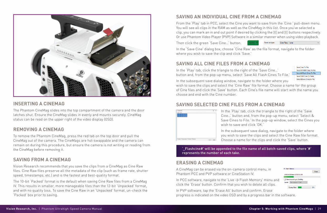
INSERTING A CINEMAGThe Phantom CineMag slides into the top compartment of the camera and the door latches shut. Ensure the CineMag slides in evenly and mounts securely. CineMag status can be read on the upper right of the video display (OSD).
REMOVING A CINEMAG To remove the Phantom CineMag, press the red tab on the top door and pull the CineMag out of the camera. The CineMags are hot-swappable and the camera can remain on during this procedure, but ensure the camera is not writing or reading from the CineMag before removing it.
SAVING FROM A CINEMAG Vision Research recommends that you save the clips from a CineMag as Cine Raw files. Cine Raw files preserve all the metadata of the clip (such as frame rate, shutter speed, timestamps, etc.) and is the fastest and best-quality format.
The 10-bit ‘Packed’ format is the default when saving Cine Raw files from a CineMag IV. This results in smaller, more manageable files than the 12-bit ‘Unpacked’ format, and with no quality loss. To save the Cine Raw in an ‘Unpacked’ format, un-check the ‘Packed’ box prior to saving.
SAVING AN INDIVIDUAL CINE FROM A CINEMAGFrom the ‘Play’ tab in PCC, select the Cine you want to save from the ‘Cine:’ pull-down menu. You will see all clips in the RAM as well as the CineMag in this list. Once you’ve selected a clip, you can mark an in and out point if desired by clicking the and buttons respectively. Or use Phantom Video Player (PVP) Software in a similar manner when using video playback.
Then click the green ‘Save Cine…’ button.
In the ‘Save Cine’ dialog box, choose ‘Cine Raw’ as the file format, navigate to the folder where you wish to save the clip and click ‘Save.’
SAVING ALL CINE FILES FROM A CINEMAGIn the ‘Play’ tab, click the triangle to the right of the ‘Save Cine…’ button and, from the pop-up menu, select ‘Save All Flash Cines To File.’
In the subsequent save dialog window, navigate to the folder where you wish to save the clips and select the ‘Cine Raw’ file format. Choose a name for the group of Cine files and click the ‘Save’ button. Each Cine’s file name will start with the name you choose and end with the Cine number.
SAVING SELECTED CINE FILES FROM A CINEMAGIn the ‘Play’ tab, click the triangle to the right of the ‘Save Cine…’ button and, from the pop-up menu, select ‘Select & Save Cines to File.’ In the pop-up window, select the Cines you wish to save and click ‘OK.’
In the subsequent save dialog, navigate to the folder where you wish to save the clips and select the Cine Raw file format. Choose a name for the clips and click the ‘Save’ button.
ERASING A CINEMAGA CineMag can be erased via the on-camera control menu, in Phantom PCC and PVP software or CineStation IV.
In PCC software, navigate to the ‘Live > Flash Memory’ menu and click the ‘Erase’ button. Confirm that you wish to delete all clips.
In PVP software, tap the ‘Erase All’ button and confirm. Erase progress is indicated on the video OSD and by a progress bar in the software.
‘_Flashcine#’ will be appended to the file name of all batch-saved clips, where ‘#’ represents the number of each take.
Vision Research, Inc. | Phantom Ultrahigh-Speed Camera Manual Chapter 5: Working with Phantom CineMags | 31
Once complete, all data on the CineMag will be erased and it will be ready for recording again immediately.
ERASE PROTECTIONIn order to protect the contents, there is a tiny erase protect switch on the front of the CineMag. When locked, the CineMag can be recorded to but not erased. If you find it impossible to erase the CineMag, check that the erase protect switch is in the unlocked position.
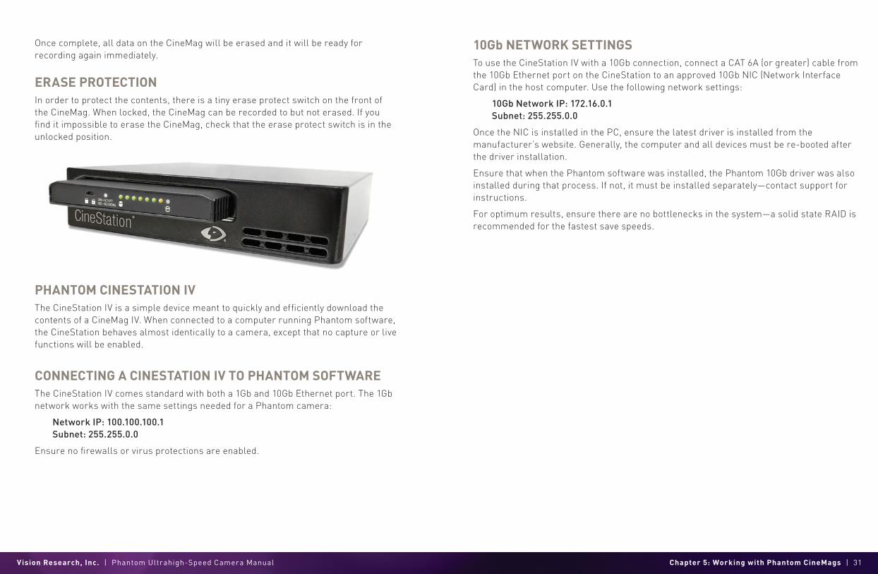
PHANTOM CINESTATION IV The CineStation IV is a simple device meant to quickly and efficiently download the contents of a CineMag IV. When connected to a computer running Phantom software, the CineStation behaves almost identically to a camera, except that no capture or live functions will be enabled.
CONNECTING A CINESTATION IV TO PHANTOM SOFTWARE The CineStation IV comes standard with both a 1Gb and 10Gb Ethernet port. The 1Gb network works with the same settings needed for a Phantom camera:
Network IP: 100.100.100.1Subnet: 255.255.0.0
Ensure no firewalls or virus protections are enabled.
10Gb NETWORK SETTINGSTo use the CineStation IV with a 10Gb connection, connect a CAT 6A (or greater) cable from the 10Gb Ethernet port on the CineStation to an approved 10Gb NIC (Network Interface Card) in the host computer. Use the following network settings:
10Gb Network IP: 172.16.0.1Subnet: 255.255.0.0
Once the NIC is installed in the PC, ensure the latest driver is installed from the manufacturer’s website. Generally, the computer and all devices must be re-booted after the driver installation.
Ensure that when the Phantom software was installed, the Phantom 10Gb driver was also installed during that process. If not, it must be installed separately—contact support for instructions.
For optimum results, ensure there are no bottlenecks in the system—a solid state RAID is recommended for the fastest save speeds.
Vision Research, Inc. | Phantom Ultrahigh-Speed Camera Manual Chapter 6: Phantom PCC Software | 33
PH
AN
TO
M
PC
C S
OF
TW
AR
E
PRE-INSTALLATION Phantom Camera Control (PCC) software is certified to operate with the following Microsoft Windows operating systems: Windows 8 and 10.
The computer and cameras must be associated with the same sub-network to communicate with one another. Typically, the IP address 100.100.100.1 and subnet 255.255.0.0 are defined to the control computer’s network card. When multiple computers are used to control the same camera, each computer requires a unique IP address. For example, 100.100.100.1 (255.255.0.0), 100.100.100.2 (255.255.0.0), and so on.
PHANTOM CAMERA CONTROL (PCC) APPLICATION OVERVIEWPhantom Camera Control software is built around a multi-layered work area that includes the following:
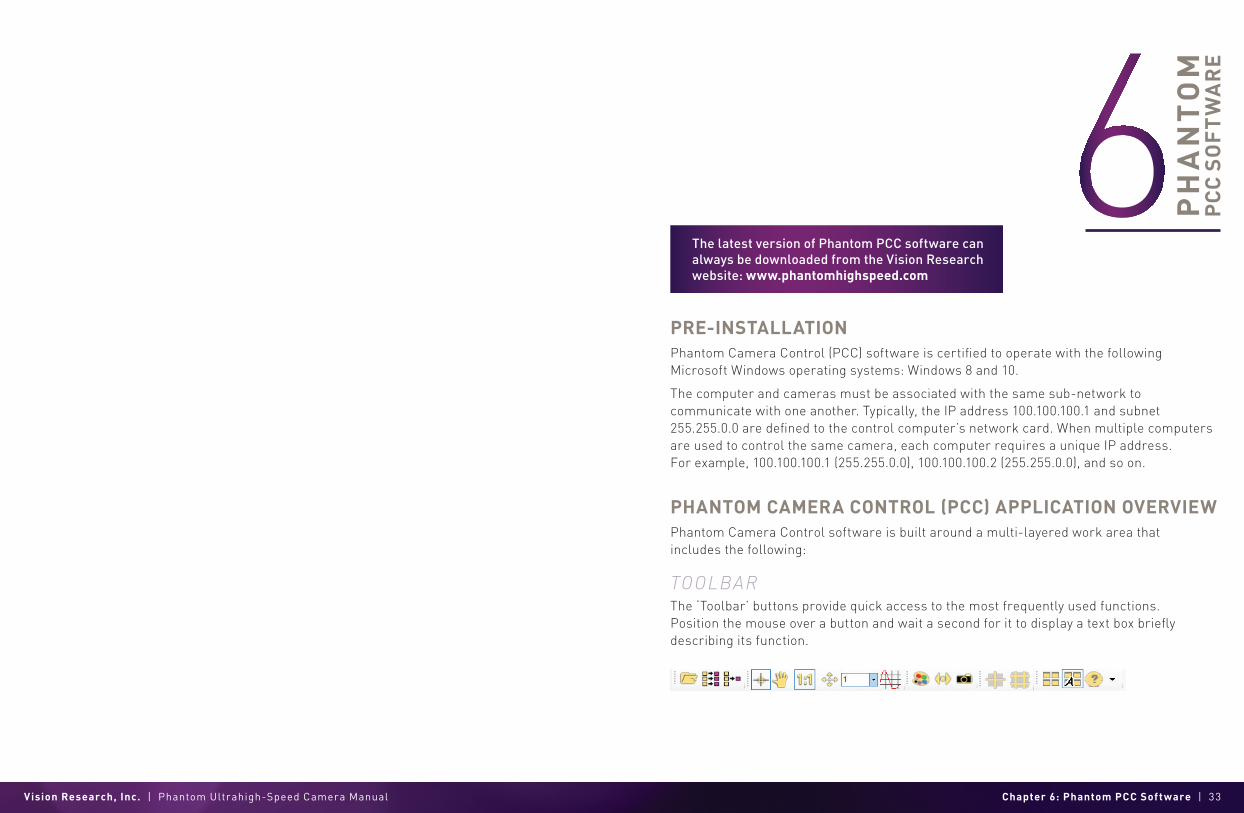
TOOLBARThe ‘Toolbar’ buttons provide quick access to the most frequently used functions. Position the mouse over a button and wait a second for it to display a text box briefly describing its function.
The latest version of Phantom PCC software can always be downloaded from the Vision Research website: www.phantomhighspeed.com

Vision Research, Inc. | Phantom Ultrahigh-Speed Camera Manual Chapter 6: Phantom PCC Software | 35
The ‘Help’ options provide valuable reference information, along with extensive documentation, relating to the software. Online tutorials can be found at www.phantomhighspeed.com/tutorials.
CONTROL TABSPCC provides three control tabs: ‘Live,’ ‘Play’ and ‘Manager.’
When first started, the ‘Manager’ tab is selected. It is in this tab that connected cameras are displayed, selected for use and renaming. It is also used to manage saved Cine files.
All camera control and capture parameters (sample rate, exposure time, etc.) are performed in the ‘Live’ tab.
Reviewing, editing and saving of Cine files, either from the camera’s internal RAM memory, installed Phantom CineMag IV or external hard drive, are performed in the ‘Play’ tab.
PHANTOM VIDEO PL AYER (PVP) APPLICATION OVERVIEW PVP can be launched directly from the desktop or by the ‘Video Out’ toolbar button in PCC.
PVP controls the video outputs (HD-SDI) connected to a computer monitor or viewfinder only.
PVP provides the ability to view, capture, review, edit and/or save a Cine recorded into the camera’s RAM, to a hard drive or installed Phantom CineMag. PVP is extremely effective when used with high-resolution cameras since most computers are not powerful enough to view live or captured raw files smoothly.
The camera’s video mode and display settings are also set through PVP. The best video system for the camera or project will vary based on the country you are in, what kind of video monitor is used and the required display resolution.
All available video systems for the connected cameras can be found in the ‘Settings’ menu of PVP, along with production area and other video overlay controls.
CAMERA CONTROL VIA PCCPCC provides the ability to select various units for specific camera parameters by clicking the ‘Preferences’ button at the bottom of the ‘Manager’ tab.
Units can be set to commonly used values (‘Presets’) or can be customized using the pull-down selection lists. First time users should use one of the three ‘Presets.’
The ‘Exp’ unit is probably the most important unit to be set. It specifies what unit to use when setting the exposure time. The other units to set are EDR and PTF (Post Trigger Frames) covered later in this section.
SELECTING A CAMERADouble-click the camera(s) to be controlled listed in the ‘Manager’ tab, or select the camera(s) from the ‘Camera’ pull-down list in the ‘Live’ tab.
Once a camera is selected, a ‘Preview’ panel will display to the left of the control tabs showing the current image being captured by the camera. This image may differ slightly to that of the image being output over the camera’s HD-SDI port due to display differences in the video monitor and computer screens.

Vision Research, Inc. | Phantom Ultrahigh-Speed Camera Manual Chapter 6: Phantom PCC Software | 37
IMAGE PROCESSING‘Image Tools’ provides extensive control over the look of the image, from color and contrast settings to image orientation and crop settings. The menu is accessed by clicking on the ‘Image Tools’ toolbar button (the one that looks like an artist’s palette).
The top of the ‘Image Tools’ window displays a ‘Histogram.’ This is a graphic representation of the pixel brightness levels of the displayed image. The left represents black, the right represents white and the height represents the proportionate number of pixels at that particular value. Unlike a waveform, the histogram’s shape is not representative of the content—it is simply an averaging of the brightness values.
Below the histogram are controls which change image settings of the live images, recorded images and the video output of the camera.
Some of the variables include; brightness, gain, gamma, saturation, toe, white balance adjustments (Temp (K) and Tint), individual red, green and blue pedestal, gain and gamma values, tone control and more.
At the bottom of the window is a ‘Default’ button that restores all parameters except white balance, tone and color matrix to their default values.
The ‘Default White Balance’ button restores white balance to the factory defaults on color cameras.
The Tone ‘Reset’ button restores the image tone to the default values, and the Color Matrix ‘Restore’ button returns the color matrix values to their default values.
The ‘Zoom Actual Size’ toolbar button resizes the images being displayed in the ‘Preview/Playback’ panel to their actual size.
The ‘Zoom Fit’ toolbar button resizes the images to fit the panel. Images can also be zoomed to a specific magnification ratio by selecting a number from the pull-down list to the right of the ‘Zoom Fit’ button.
Changes made here only affect the metadata of the Cine Raw file. They are applied in software but not “baked in.” If you are saving to a different format or recording the video output, ensure everything is set to values that produce the image you wish to record.
AUTOMATIC WHITE BAL ANCEPerforming a ‘White Balance’ should be the first step in color adjustment. (White Balance not applicable to monochrome cameras.)
Right click on an area that resembles white in the image in the ‘Preview’ or ‘Playback’ panel, then click on the ‘White Balance’ pop-up window. It is not necessary to fill the frame with white—a small target can be used.
It is recommended to perform the White Balance after a CSR and on a white or gray object that is not fully saturated.
CAPTURE SETUPJust below the ‘Camera’ selector in the ‘Live’ tab are a series of expandable headers, which contain groups of related camera settings.
CAMERA SET TINGS & CINE SET TINGS Set Time: Synchronizes the timestamps embedded in the recorded image data to the computer’s clock.
Bit Depth: All Phantom UHS cameras operate in 12-bit mode only.
Partitions: Select the number of desired partitions (evenly divided memory segments) from the ‘Partitions’ pull-down menu. For basic camera setups, this should be set to one.
This manual will cover the most commonly used settings—see the ‘PCC Help’ file for details of other settings.

Vision Research, Inc. | Phantom Ultrahigh-Speed Camera Manual Chapter 6: Phantom PCC Software | 39
Sensor Acquisition Mode: Used by the v1840 and v2640 to select the required operational mode of the sensor. When the operating mode is changed, settings default to factory settings for that mode.
Lens Control: Available for Canon EF lenses only, for control of aperture and focus.
Backup & Restore: Allows for user and factory settings to be saved and recalled from the camera’s memory.
Resolution: Sets the camera’s acquisition resolution. There are several options in the pull-down menu. Alternatively, type in a value and the closest valid resolution will be set.
Sample Rate: Sets the acquisition frame rate in frames-per-second (fps).
Exposure Time (shutter): Sets the exposure time in degrees, microseconds or percentage (this depends on how the PCC preferences are set).
EDR (Extreme Dynamic Range): Sets a secondary exposure time to pixels that may become fully saturated or overexposed. This is valuable for monochrome cameras, but be careful with color cameras as a color cast will occur on the areas of the image to which EDR is applied.
Exposure Index: Sets the exposure index (Effective ISO) of the image by loading preset tone curves. Adjusting gamma, gain and other settings will contribute to the overall EI value, and this combined value is what should be used to determine lighting.
CSR (Current Session Reference): Closes the camera’s internal shutter and resets the black point of every pixel for optimal image quality.
Image Range and Trigger Position: The slider represents the memory buffer, with the ‘Duration’ indicated in seconds and the total number of frames available.
The trigger position is indicated in the ‘Last’ pull-down menu and as the ‘T’ slider along the timeline. The trigger position is exactly when the trigger signal will be detected in the Cine.
KEY ADVANCED SET TINGSThe “Start/End of Recording Actions” section provides options of actions that can automatically be performed at the start or end of each shot, including:
• ‘Auto save to CineMag/Built-in Flash’: This feature saves a user-specified portion of a clip to the Phantom CineMag immediately after recording.
• ‘Auto play Video Out’: Begins playback after recording. The range marked under ‘Auto play Video Out’ affects both playback and saving to the Phantom CineMag.
• ‘Restart Recording’: When enabled, automatically restarts the recording process after the ‘Auto’ actions have been performed.
‘External Sync’ instructs the camera to utilize one of the following frame sync clock options:
• Internal: Instructs the camera to utilize its internal crystal oscillator to drive the camera’s frame rate.
• External: Should be selected when an externally supplied frame sync clock pulse is supplied to drive the frame rate. This can be used to synchronize two cameras together via F-Sync.
• IRIG: Should be selected when an IRIG-B signal is supplied to drive the camera’s frame rate.
• LockToVideo: Frame rate is driven by the camera’s current video rate. Fps will jump to the closest multiple of the current video rate (23.98, 24, 25, 29.97 or 30).
• Sync to Trigger: Instructs the camera to adjust its frame clock, upon detection of a trigger signal, to ensure all post trigger frames occur at the same moment in time from trigger when repetitive tests are required.
FL ASH MEMORYSpecifies the camera’s operation mode in relation to CineMag recording: ‘Loop’ (record to RAM first) or ‘R/S’ (bypass RAM and record directly to CineMag). It also displays the amount of free space and size (in Gigabytes) of the Phantom CineMag.
RECORDING A CINETo begin recording to the camera’s RAM click the red ‘Capture’ button.
The red ‘Capture’ button changes to ‘Abort Recording’ and the green ’Trigger’ button is enabled when the camera is recording. The ‘Abort Recording’ button instructs the camera to stop recording, leaving the camera’s RAM empty.

Vision Research, Inc. | Phantom Ultrahigh-Speed Camera Manual Chapter 6: Phantom PCC Software | 41
TRIGGERING THE CAMERASelecting the ‘Trigger’ button instructs the camera to immediately stop recording when the ‘Trigger Position’ is set to zero. If a value greater than zero is set, the camera will continue to record ‘post-trigger’ frames until the user-specified value is met.
Set ‘R/S’ (Run/Stop) mode by selecting the ‘Direct Recording to CineMag’ box in the ‘Flash Memory’ section. Start recording by clicking the red ‘Record’ button. Once the camera is recording directly to the Phantom CineMag, the ‘Record’ button changes to a ‘Stop Recording’ button.
REVIEWING A CINEOnce the camera has completed recording a Cine in the camera’s RAM or CineMag, it can be reviewed by selecting it from the ‘Cine’ pull-down selection list in the PCC ‘Play’ tab.
A previously saved Cine stored on the computer’s hard drive can be opened using the ‘Open File’ toolbar button. (When utilized, it also places the file under the ‘Cines’ group folder in the ‘Manager’ tab.)
Playback can be changed via the ‘Play Speed & Options’ and the Cines’ metadata can be viewed in the ‘Frame Info’ and ‘Cine Info’ sections.
Use the ‘Video Control’ buttons to review the Cine:
PERFORMING A QUICK SE ARCH THROUGH A CINEQuickly search through Cine files to find the points of interest:
‘Scroll’ (scrub) through the clip using the ‘Image Location’ slider or click anywhere on the timeline to jump to points in the Cine quickly.
‘Jump’ to the trigger frame by clicking on the ‘T’ button, or jump to specific frames by entering the frame number into the jump ‘#’ data entry field, then hit the enter key.
‘Image Search.’ The goal is to search or find an image change in the recording, based on the differences between image content. Right-click on the ‘Play’ button to begin the image search. Besides image content changes, ‘Image Search’ can also look for images that are tagged as ‘Event’ images.
EDITING A CINEUsing the following ‘Video Control’ buttons, locate the first image of the Cine to be saved and click the ‘Mark-In’ button.
Locate the last image of the Cine to be saved and click the ‘Mark-Out’ button.
Click ‘Play, Speed & Option’ and enable (check) ‘Limit to Range.’
Under the ‘Video Control’ buttons, click the ‘Jump to Start’ button and review the edited Cine.
If a clip exists in the camera’s memory, you will be asked if you are sure you wish to delete it before continuing. If yes, click ‘Delete Cine(s) and Start New Recording.’
Using the camera’s ‘Trigger’ button, or an external trigger signal, provides a more accurate trigger to the camera.
A
B
C
D
E
F
REVERSE PLAY
PAUSE
PLAY
REVERSE 1-FRAME
FAST REVERSE
ADVANCE 1-FRAME
G FAST FORWARD

Vision Research, Inc. | Phantom Ultrahigh-Speed Camera Manual Chapter 6: Phantom PCC Software | 43
SAVING A CINE Click the ‘Save Cine...’ button to save the edited Cine to the computer’s hard drive.
If you wish to save the clip to an attached Phantom CineMag, click the down arrow to the right of the ‘Save Cine...’ button and select ‘Save RAM Cine to Flash.’
WORKING WITH CINE FILESThe images recorded on the camera’s RAM or Phantom CineMag are stored in a Vision Research proprietary RAW (uncompressed) file structure called a ‘Cine’ file.
These Cine files can be converted to industry standard formats (ProRes, H264, DPX, DNG, TIFF, JPEG and more) with PCC software provided by Vision Research.
Phantom PCC and PVP software are only compatible with Windows operating systems. However, there are third party solutions available for working with Phantom cameras in Mac OS X.
COMPATIBILIT Y WITH VIDEO EDITING PROGRAMSSeveral popular video editing programs, such as DaVinci Resolve and Adobe Premiere, have incorporated the Phantom Cine Raw file format into their software. This means Cine files do not have to be converted and no additional software is required.
Please test the footage with the program you choose before committing, as updates to the program or Cine file format can sometimes break compatibility. For this reason, it is important to know how to properly convert Cine Raw files using PCC.
CONVERTING CINE RAW FILESSingle Cine files can be converted by selecting the desired format from the ‘Save as Type’ selection list in the ‘Save Cine’ dialogue window.
The file formats above the separator line in the ‘Save as Type’ selection list are ‘movie-like’ formats (meaning the entire clip will be saved as a single file), while the formats below the line are image formats (meaning each frame of Cine will be saved as a sequence of images).
To convert a Cine to a ‘movie-like’ format, select the desired format from the list, navigate to the destination folder, assign a file name to the clip and save.
Some valuable parameters can be found in the ‘Advanced Settings’ window, such as the particular codec.
Other formats, like .avi and .mp4, allow the compression ratio to be entered. The lowest compression is the default.
CONVERTING TO A SERIES OR STACK OF IMAGESTo convert a Cine clip into a sequence of images (frames), you must add one of the following annotations to the end of the file name: ‘!n’ or ‘+n’ (where n is a number between 1 and 8). This will assign the sequential frame numbers to the file name for each frame being created. Example: image_!5.tif
The ‘!’ annotator instructs the software to append the Cine’s image number (relative to the trigger point) to the file name. If the first frame in the clip is -100, then the first converted frame will have the name: image_-00100.tif
The ‘+’ annotator will add frame numbers starting from 1. Example: image_+5.tif. This will cause the first converted frame to have the name: image_00001.tif
BATCH CONVERTThe ‘Batch Convert Files’ toolbar button can be used to convert a single saved Cine file, or multiple saved Cine files, into any one of the supported file formats.
Use the shift and/or control keys to select the Cine files you wish to convert in the ‘Open Cine’ dialogue window, then click the ‘Open’ button.
Navigate to the destination folder in the ‘Multifile Convert Destination’ dialogue window and select the file format. The ‘File Name’ will depend on the type of file format you are converting to.
Re-saving a clip in the ‘Cine Raw’ format can be useful for creating sub-clips with no loss in image quality or metadata.
Ensure all image adjustments have been applied prior to initiating the conversion process. All metadata (gain, gamma, saturation, etc.) will be embedded into the converted images.
Vision Research, Inc. | Phantom Ultrahigh-Speed Camera Manual Chapter 7: Programmable I/O Signal Architecture | 45
If you are converting the Cine file into a ‘movie-like’ format, leave the file name as ‘All Selected File.’ The software automatically assigns the original file name to the converted file.
If converting each Cine file into a sequence of images, then the ‘+’ or ‘!’ annotators must be used, followed by the specified number (example: image+5).
PCC creates a separate folder for each Cine file, assigns the original file name and appends the appropriate image number and extension to each image.
Once the ‘Convert’ button is clicked, a progress window appears for the duration of the conversion process. Each converted Cine will be placed in its own folder named after the original Cine file.
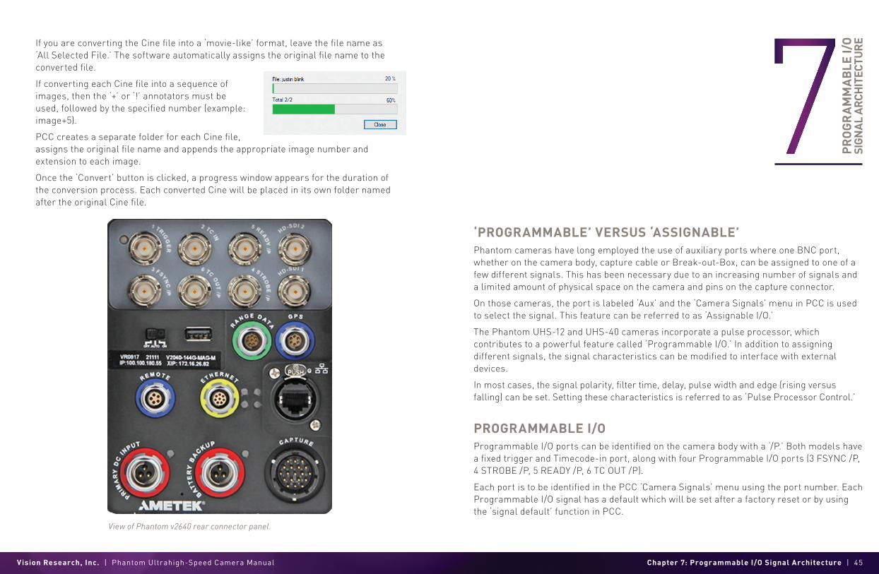
View of Phantom v2640 rear connector panel.
PR
OG
RA
MM
AB
LE I/
O
SIG
NA
L A
RCH
ITEC
TUR
E
‘PROGRAMMABLE’ VERSUS ‘ASSIGNABLE’ Phantom cameras have long employed the use of auxiliary ports where one BNC port, whether on the camera body, capture cable or Break-out-Box, can be assigned to one of a few different signals. This has been necessary due to an increasing number of signals and a limited amount of physical space on the camera and pins on the capture connector.
On those cameras, the port is labeled ‘Aux’ and the ‘Camera Signals’ menu in PCC is used to select the signal. This feature can be referred to as ‘Assignable I/O.’
The Phantom UHS-12 and UHS-40 cameras incorporate a pulse processor, which contributes to a powerful feature called ‘Programmable I/O.’ In addition to assigning different signals, the signal characteristics can be modified to interface with external devices.
In most cases, the signal polarity, filter time, delay, pulse width and edge (rising versus falling) can be set. Setting these characteristics is referred to as ‘Pulse Processor Control.’
PROGRAMMABLE I/OProgrammable I/O ports can be identified on the camera body with a ‘/P.’ Both models have a fixed trigger and Timecode-in port, along with four Programmable I/O ports (3 FSYNC /P, 4 STROBE /P, 5 READY /P, 6 TC OUT /P).
Each port is to be identified in the PCC ‘Camera Signals’ menu using the port number. Each Programmable I/O signal has a default which will be set after a factory reset or by using the ‘signal default’ function in PCC.

Vision Research, Inc. | Phantom Ultrahigh-Speed Camera Manual Chapter 7: Programmable I/O Signal Architecture | 47
SIGNAL ASSIGNMENTS
PCC INTERFACEThe ‘Camera Signals’ menu, located in the ‘Live’ tab, provides access to and control over these Programmable I/O signals. All listed signals are not active, including ‘Runstop’ and ‘Mstrobe.’
A summary of the current signal settings is found under the pull-down menu associated with each port. By clicking ‘Default All,’ PCC will reassign the factory-assigned defaults for the Programmable I/O signals.
PULSE PROCESSOR CONTROL After selecting the signal assignment, further configuration is possible by clicking the gear symbol next to each port. The ‘Pulse Control’ menu is opened, as shown on the next page.
A graphic representation of the signal behavior is also displayed. However, this is not to scale and should be used as reference only. Use of this feature requires an oscilloscope to truly visualize the signals and the subsequent changes with each adjustment.
SUMMARY OF PULSE PROCESSOR SETTINGS Invert: Inverts the signal at the output of the pulse processor.
Falling: Selects ‘Falling Edge’ mode for the pulse processor. This mode is only relevant if the ‘Width’ is also specified. When the ‘Falling’ token is present together with ‘Width,’ the pulse processor will generate a negative pulse, triggered from the negative edge of the input signal.
Width (Pulse Width): When a ‘Width’ token is present, a defined-length pulse is generated, which starts after the specified ‘Delay’ and after the active edge of the ‘input’ signal. The length of the pulse is specified in microseconds (as a floating point number) and internally converted to pixel clock units. The maximum pulse width is at least 10 seconds. However, if the period of the ‘input’ signal is lower than the selected width, the latter is dynamically clamped to the signal period. The minimum pulse width is one pixel clock.
Delay: Delays the output pulse by the specified time in ms, µs or camera clock multiples. If the ‘Width’ token is not present, both edges of the signal are delayed by the same amount. If present, the delay is measured from the rising edge of the input* signal unless the ‘Falling’ token is present, in which case the delay is measured from the falling edge of the input. The delay time is specified in microseconds (as a floating point number) and is internally converted and routed to pixel clock units.
*Input: When a signal is generated by the camera, it serves as an input to the ‘pulse processor.’ In this context, the term ‘ input’ does not represent an externally generated signal.
SIGNAL ASSIGNMENTPort 1 Trigger (fixed)
Port 2 Timecode-in (fixed)
Port 3 (P3) Prog I/O-Default F-Sync
Port 4 (P4) Prog I/O-Default Strobe
Port 5 (P5) Prog I/O-Default Ready
Port 6 (P6) Prog I/O Default Timecode-out
Range Data Yes, dedicated Fischer port
Vision Research, Inc. | Phantom Ultrahigh-Speed Camera Manual Chapter 7: Programmable I/O Signal Architecture | 49
Filter (Filter Time): When a ‘Filter’ token is present, the ‘input’ of the pulse processor is filtered through an edge filter of the specified time. The time of the filter can be between 0 and 1 second. In order for the output of the filter to be asserted, the ‘input’ signal must be continuously de-asserted for the same duration. The edges of the ‘input’ are thus delayed by the specified filter time (for a ‘clean’ input pulse). Filtering is applied before and independently of the delay and duration. The filter time is specified in microseconds (as a floating point number) and is internally converted and routed to pixel clock units.
PIXEL CLOCK The period of the pixel clock is the basic time interval for all camera timing.
Please note that pulse processors can sometimes generate pulses that are too short for the output drivers to switch properly and, as such, the processed signal should be verified with an oscilloscope before use.
PROGRAMMABLE SIGNALS & DESCRIPTIONS Ready: An isolated open collector output with 1k pull-up signal (active high). ‘Ready’ is asserted when the camera goes into ‘Capture’ mode and is de-asserted either when the Cine is triggered or when the Cine recording is completed. ‘Ready’ changes synchronously with frame capture (at the end of each exposure), so in ‘External Sync’ mode it will not change until F-Sync pulses are received.
Strobe: An isolated open collector output signal with 1k pull-up. When asserted (low) ‘Strobe’ indicates that the camera integrates. (The electronic shutter is open.) Strobe is low for the duration of the exposure.
F-Sync: The only signal can be set as an output or input. By default, it is output (sync-internal). Output signal is a frame sync pulse from the camera’s frame rate generator. A short (few hundred ns depending on camera model) negative pulse with the falling edge is used as timing reference. Input signal is active on falling edge. (Default state is high.)
TC-Out: A positive polarity time code signal. Normally an unmodulated (dc-shifted) IRIG-B (at RS-232 levels) which follows the internal time base of the camera. It is recommended not to process the ‘TC-Out,’ since a processed signal may no longer represent a standard or accurate time code.
Auto-Trigger: Used to output a hardware trigger signal or pulse with the duration.
Software Trigger: An active high-output signal (pulse) generated as a result of the trigger protocol command.
Recording: An active high-output signal. When active, indicates the camera is recording into a RAM partition.
Event In: If the input is sampled low at the end of an exposure, an ‘E’ (Event) bit in the frame’s timestamp is set.
Memory Gate In: If the input is sampled low at the end of an exposure, the corresponding frame is skipped from storage to RAM.
Pre-trigger: An active low-input (default high) signal. Keeping this signal low for enough time (10—500 ms or until ‘Ready’ signal goes high) will make the camera start recording, if it has an available RAM partition.
Aux Trigger: An input signal active on the rising edge (default high). This is an alternative trigger input that can be processed through the programmable port pulse processors and assigned to different ports.
THE CORE SIGNALSCore signals are copies of externally generated signals, routed through the camera and output to assigned ports. Core signals can be pulse-processed before being output.
The current list of signals is:
Core Event: Feedback output from the ‘Event In’ signal. The feedback is taken after any pulse processor for the output.
Core Memory Gate: Feedback output from the ‘Memory Gate In’ signal. The feedback is taken after any pulse processor for the output.
Core Frame Sync: Feedback output from the ‘F-Sync In’ signal. The feedback is taken after any pulse processor for the output, but before the delay element.
Core Pre-trigger: Feedback output from the ‘Pre-trigger’ signal. The feedback is taken after any pulse processor for the input.
Core Aux Trigger: Feedback output from the ‘Aux Trigger In’ signal. The feedback is taken after any pulse processor for the input.
Core Trigger: Feedback output from the main ‘Trigger’ input. The feedback is taken before the trigger signal is affected by the trigger polarity, filter or delay settings. ‘Core Trigger’ can be used like the ‘Trigger Out’ signal.
All descriptions are the signal’s default state prior to processing.

Vision Research, Inc. | Phantom Ultrahigh-Speed Camera Manual Chapter 8: Measurements | 51
ME
ASU
REM
ENTS
INTRODUCTION Included in PCC is a set of 2D motion analysis tools which go a step beyond the visual when it comes to providing valuable data about the subject. Analysis can perform timing, position, distance, velocity, angle and angular speed measurements, as well as track multiple points to compute and graph their XY-coordinates, speed or acceleration. The interface can also harmonize this measured data with images.
This chapter reviews various PCC measurement capabilities. Further documentation, including step-by-step procedures, can be found in the PCC help documentation available within the software.
TIMING MEASUREMENTSPCC utilizes the timestamp (date and time) embedded in every frame captured to accurately calculate time differences between two images (start/end of an event) or from the image being displayed in the ‘Playback’ panel and the trigger (t0) frame automatically.
To perform a timing measurement, click the ‘Frame Info’ selector. Locate the first image of the event and enter its image number (found above the center of the Cine editor bar) into the ‘Elapsed Time’ from: ‘Image#’ data entry field. Advance the Cine to the end of the event image.
PCC displays the time difference between the two images (start/end of event images) next to the Elapsed Time from fields; Elapsed Time from Trigger and Elapsed Time from: Image#.
Vision Research, Inc. | Phantom Ultrahigh-Speed Camera Manual Chapter 8: Measurements | 53
UNITS OF MEASUREMENTEstablishing the measurement ‘Units’ is an important first step to using the measure functions. ‘Units of Measurement’ specify the computing and reporting units for distance, speed, acceleration, angle and angular speed measurements.
Define the ‘Measurement Units’ in the ‘Preferences’ menu, accessible by clicking the wrench button from the ‘Manager’ tab. Open the ‘Measurement’ tab and select desired measurement ‘Units’ and ‘Other Options.’
‘Other Options’ in ‘Measurement Preferences’ include:
Unique scale per application: When enabled, the same scale will be applied to all subsequent opened Cines.
Auto advance to next image during collect points: The Cine advances to the next image automatically once all the collect (tracking) points have been manually specified on the displayed image. This option should be disabled (unchecked) if auto tracking points is to be used.
Auto update graphics during collect points: A graphical display of the tracked points will overlay the images during the collect point process.
MEASUREMENT SELECTORPCC measurement functions are found in the ‘Play’ tab and will work with saved files (Cine Raw or converted files) or directly from the camera’s RAM playback.
Calibration: To define a measurement scale, the first step is to use the ‘Calibrate’ function in the image with a known scale.
Click the ‘Calibrate’ button and specify both ends of the scale by clicking both end points of the scale. In the ‘Set Gauge’ dialogue window, enter the scale size. Once created, all measurements are computed and displayed using the scale unit.
Axes: Coordinate measurements are calculated from an ‘Origin’ point pixel, by default the top-left corner of the image. However, the ‘Origin’ can be changed when performing measurements. Each coordinate consists of two numbers (x1, y1) indicating the position of a pixel in the image on the two-dimensional plane from the ‘Origin’ point.
Your choice of origin will be largely dependent on the subject and the type of motion being studied.
Once the origin point is set, activate ‘Instant Measurements’ and select one of the available options for Distance, Angle, Speed and Angular Speed.
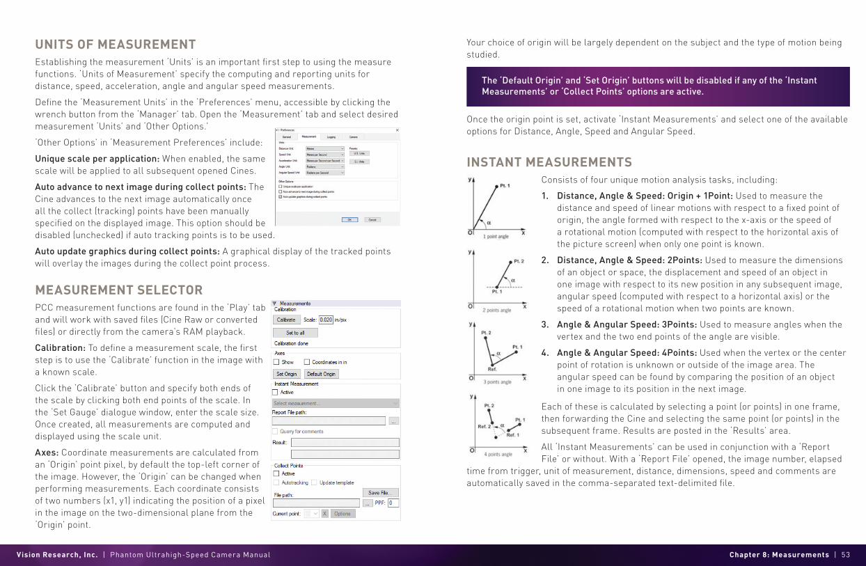
INSTANT MEASUREMENTSConsists of four unique motion analysis tasks, including:
Each of these is calculated by selecting a point (or points) in one frame, then forwarding the Cine and selecting the same point (or points) in the subsequent frame. Results are posted in the ‘Results’ area.
All ‘Instant Measurements’ can be used in conjunction with a ‘Report File’ or without. With a ‘Report File’ opened, the image number, elapsed
time from trigger, unit of measurement, distance, dimensions, speed and comments are automatically saved in the comma-separated text-delimited file.
1. Distance, Angle & Speed: Origin + 1Point: Used to measure the distance and speed of linear motions with respect to a fixed point of origin, the angle formed with respect to the x-axis or the speed of a rotational motion (computed with respect to the horizontal axis of the picture screen) when only one point is known.
2. Distance, Angle & Speed: 2Points: Used to measure the dimensions of an object or space, the displacement and speed of an object in one image with respect to its new position in any subsequent image, angular speed (computed with respect to a horizontal axis) or the speed of a rotational motion when two points are known.
3. Angle & Angular Speed: 3Points: Used to measure angles when the vertex and the two end points of the angle are visible.
4. Angle & Angular Speed: 4Points: Used when the vertex or the center point of rotation is unknown or outside of the image area. The angular speed can be found by comparing the position of an object in one image to its position in the next image.
The ‘Default Origin’ and ‘Set Origin’ buttons will be disabled if any of the ‘Instant Measurements’ or ‘Collect Points’ options are active.
Vision Research, Inc. | Phantom Ultrahigh-Speed Camera Manual Chapter 8: Measurements | 55
COLLECT POINTSCollect Points: Point data (for up to 99 points-per-image) can be collected and tracked within PCC software and imported by third party programs. This feature creates a separate comma-separated text-delimited file for coordinates, speed and/or acceleration.
COLLECT POINT DATA FOR TRACKING The point data can be collected two ways:
1. Manual Track: Used to track point positions (coordinates) from one image to the next once its starting point is defined.
2. Auto Track: Used to track point positions from one image to the next once its starting point is defined.
‘Auto Tracking’ is done during the play of the Cine (step forward, step backward, play forward, play reverse). It is very important that the images be in succession; ‘Auto Tracking’ will self-disable if they are not. To avoid this from occurring, ‘Play Speed & Options>Play Each Image’ is forced on. It will also disable itself when jumping from the last image to the first. However, the points will remain attached to those areas in the image, as they are stored in the user-specified ‘.ppf’ (pictures-per-frame) file. This allows the end-user to reopen a Cine and/or picture-per-frame file to overlay the points, or export the file to a spreadsheet.
AUTOTRACKING STEP-BY-STEPAfter the measurement units, calibration and origin points have been defined:
1. Locate the first frame with the points to be tracked.
2. Create a ‘.ppf’ (picture-per-frame) file by clicking the ‘...’ button near the ‘File Path’ box under ‘Collect Points.’
3. Navigate to the folder to save the ‘.ppf’ file, enter a name and click the ‘Open’ button.
4. Specify the number of points to be collected (tracked) in the ‘PPF’ field (99 max.).
5. Enable the ‘Active’ box.
6. Click the center of the point(s) to be tracked. Ideally, the selected points should be a small target or the edge of an object that will be in motion. Do this until all points have been manually specified. If the ‘Auto advance to next image during collect points’ has been enabled in the ‘Preferences>Measurements’ tab, step backward to the image with the defined points.
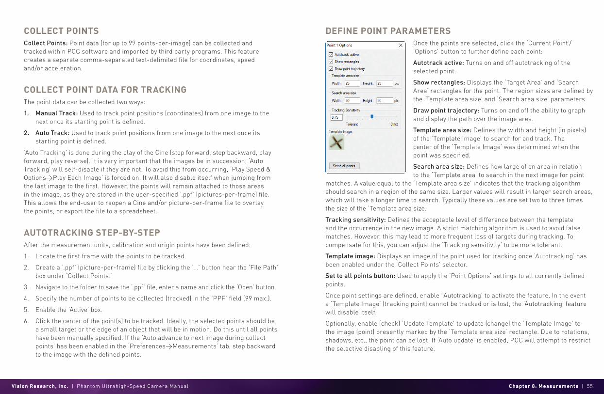
DEFINE POINT PARAMETERS Once the points are selected, click the ‘Current Point’/ ‘Options’ button to further define each point:
Autotrack active: Turns on and off autotracking of the selected point.
Show rectangles: Displays the ‘Target Area’ and ‘Search Area’ rectangles for the point. The region sizes are defined by the ‘Template area size’ and ‘Search area size’ parameters.
Draw point trajectory: Turns on and off the ability to graph and display the path over the image area.
Template area size: Defines the width and height (in pixels) of the ‘Template Image’ to search for and track. The center of the ‘Template Image’ was determined when the point was specified.
Search area size: Defines how large of an area in relation to the ‘Template area’ to search in the next image for point
matches. A value equal to the ‘Template area size’ indicates that the tracking algorithm should search in a region of the same size. Larger values will result in larger search areas, which will take a longer time to search. Typically these values are set two to three times the size of the ‘Template area size.’
Tracking sensitivity: Defines the acceptable level of difference between the template and the occurrence in the new image. A strict matching algorithm is used to avoid false matches. However, this may lead to more frequent loss of targets during tracking. To compensate for this, you can adjust the ‘Tracking sensitivity’ to be more tolerant.
Template image: Displays an image of the point used for tracking once ‘Autotracking’ has been enabled under the ‘Collect Points’ selector.
Set to all points button: Used to apply the ‘Point Options’ settings to all currently defined points.
Once point settings are defined, enable “Autotracking’ to activate the feature. In the event a ‘Template Image’ (tracking point) cannot be tracked or is lost, the ‘Autotracking’ feature will disable itself.
Optionally, enable (check) ‘Update Template’ to update (change) the ‘Template Image’ to the image (point) presently marked by the ‘Template area size’ rectangle. Due to rotations, shadows, etc., the point can be lost. If ‘Auto update’ is enabled, PCC will attempt to restrict the selective disabling of this feature.

Vision Research, Inc. | Phantom Ultrahigh-Speed Camera Manual Chapter 8: Measurements | 57
GRAPHICSOptionally, click the ‘Graphics’ toolbar button to view a chart of the tracked points. This opens a graphical interface (displayed to the right of the Cine image) which is used to display signal acquisition information or position/speed/acceleration, and the coordinate X or Y of tracked collect points. The displayed values take into account the global measurement preferences for position/speed/acceleration. Only windows for the types of signals that are present in the .Cine file will be available.
FINISHING STEPS 1. Deactivate (uncheck) ‘Collect Points.’
2. Click the ‘Save’ button to save the completed points and computation files that are required.
DATA ACQUISITION To investigate the effect environmental conditions may have on the recorded data, a National Instruments™ USB- or M-Series Data Acquisition (DAQ) module can also be used to acquire data from a wide range of sensors and synchronize it with slow-motion video images recorded on a Phantom camera, using Phantom Camera Control (PCC) software.
SYSTEM DEVELOPER KIT (SDK) Phantom Camera Control, Cine playback, analysis and measurements can be customized to meet specific test protocols using the Phantom System Developer Kit (SDK) for LabVIEW (Laboratory Virtual Instrument Engineering Workbench) or MATLAB (Matrix Laboratory) drivers.
The LabVIEW SDK contains visual instrument (VI) files needed to call Phantom SDK functions from LabVIEW, various utilities and demo applications. This SDK uses the LabVIEW interface to shared libraries to call functions from Phantom libraries.
The MATLAB SDK contains header files needed to call Phantom SDK functions from MATLAB, function wrappers, a simple object-oriented layer and demo scripts. This SDK uses the MATLAB interface to shared libraries to call functions from Phantom libraries.
SDKs allow, for example, automotive manufacturers to create command line scripts to control a Phantom camera directly from a computer or run in a Graphical User Interface specifically designed to perform or analyze airbag tests without having to use PCC. Anyone who wishes to have more control over their Phantom camera or the Cine files recorded would benefit from using one of these Phantom System Developer Kits.

Vision Research, Inc. | Phantom Ultrahigh-Speed Camera Manual Chapter 9: Accessories | 59
AC
CE
SSO
RIE
S
INTRODUCTION Phantom Ultrahigh-Speed cameras are shipped in a sturdy Pelican case with a power supply, Ethernet cable, PCC software and printed manual.
There are accessories to facilitate the use of the cameras for different applications.
VIEWFINDER & MONITOR OPTIONSViewfinders and monitors are available from third party sources.
In identifying a compatible unit, note that Phantom Ultrahigh-Speed cameras include a component video port, which is directly compatible with inexpensive component video monitors by using a Phantom YPRPB cable (Part #VRI-CBL-YPRPB-P65-0R8).
BATTERIESBatteries are available from third party sources.
For compatible units, Phantom UHS-12 and UHS-40 cameras come with a 3-pin Fischer connector labeled ‘Battery Backup.’ The battery must be able to supply 200W at greater or equal to 20V to be compatible.
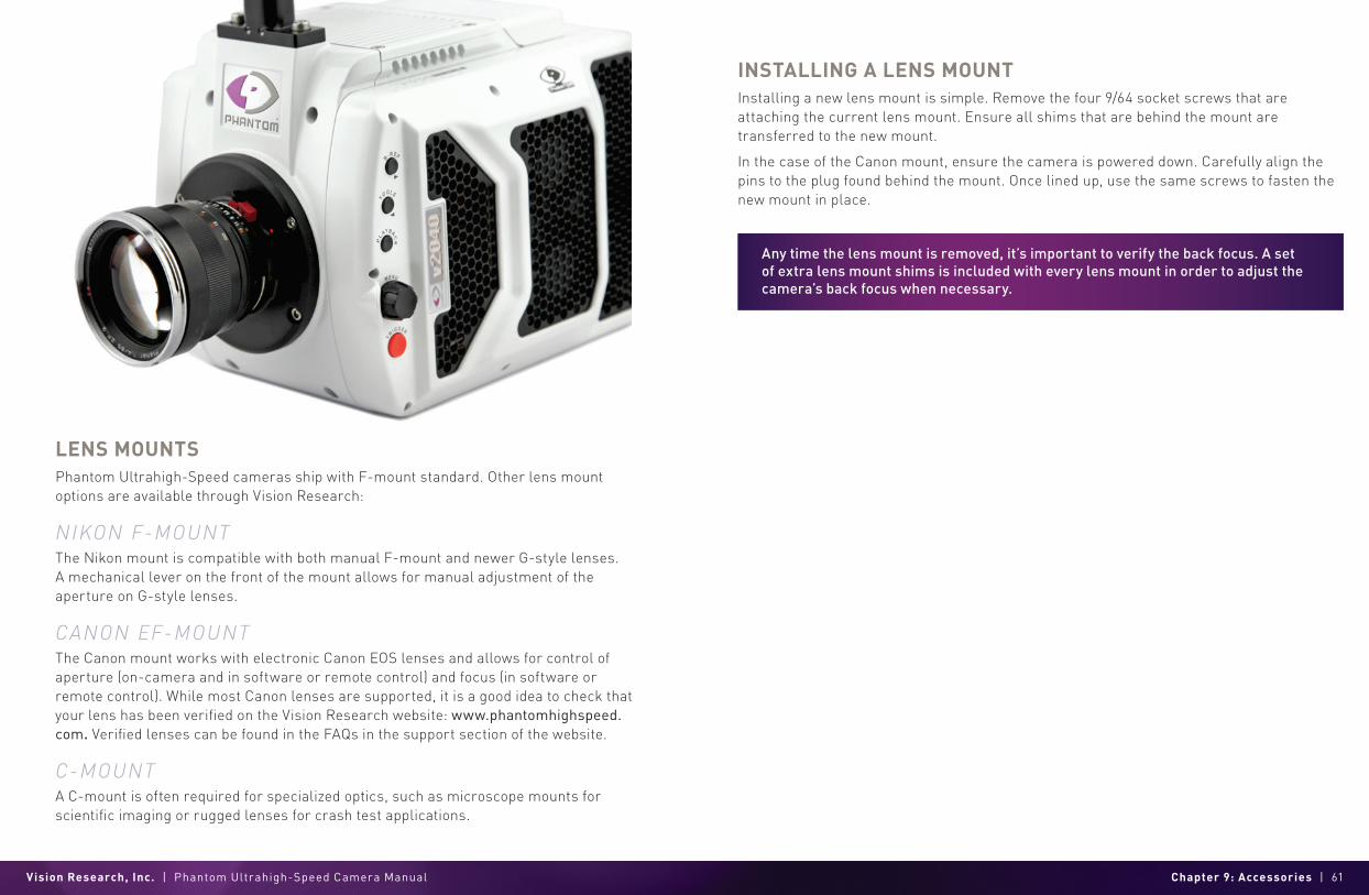
Vision Research, Inc. | Phantom Ultrahigh-Speed Camera Manual Chapter 9: Accessories | 61
Any time the lens mount is removed, it’s important to verify the back focus. A set of extra lens mount shims is included with every lens mount in order to adjust the camera’s back focus when necessary.
LENS MOUNTS Phantom Ultrahigh-Speed cameras ship with F-mount standard. Other lens mount options are available through Vision Research:
NIKON F-MOUNTThe Nikon mount is compatible with both manual F-mount and newer G-style lenses. A mechanical lever on the front of the mount allows for manual adjustment of the aperture on G-style lenses.
CANON EF-MOUNTThe Canon mount works with electronic Canon EOS lenses and allows for control of aperture (on-camera and in software or remote control) and focus (in software or remote control). While most Canon lenses are supported, it is a good idea to check that your lens has been verified on the Vision Research website: www.phantomhighspeed.com. Verified lenses can be found in the FAQs in the support section of the website.
C-MOUNTA C-mount is often required for specialized optics, such as microscope mounts for scientific imaging or rugged lenses for crash test applications.
INSTALLING A LENS MOUNTInstalling a new lens mount is simple. Remove the four 9/64 socket screws that are attaching the current lens mount. Ensure all shims that are behind the mount are transferred to the new mount.
In the case of the Canon mount, ensure the camera is powered down. Carefully align the pins to the plug found behind the mount. Once lined up, use the same screws to fasten the new mount in place.

Vision Research, Inc. | Phantom Ultrahigh-Speed Camera Manual Chapter 10: FAQs & Support | 63
FAQ
s &
SU
PP
OR
T
M E C H A N I C A L D R A W I N G S
FRONT VIEW(with and without CineMag)
RE AR VIEW(with and without CineMag)
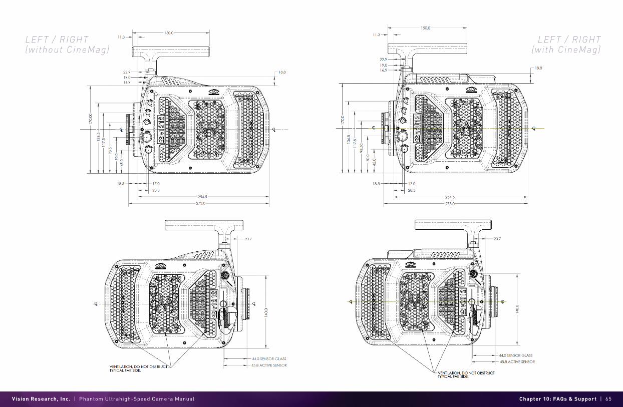
Vision Research, Inc. | Phantom Ultrahigh-Speed Camera Manual Chapter 10: FAQs & Support | 65
LEF T / RIGHT(without CineMag)
LEF T / RIGHT(with CineMag)
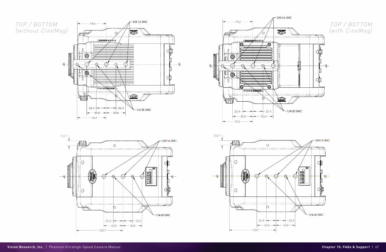
Vision Research, Inc. | Phantom Ultrahigh-Speed Camera Manual Chapter 10: FAQs & Support | 67
TOP / BOT TOM(without CineMag)
TOP / BOT TOM(with CineMag)

Vision Research, Inc. | Phantom Ultrahigh-Speed Camera Manual Chapter 10: FAQs & Support | 69
C O N N E C T O R P I N - O U T S
PHANTOM UHS-12 & UHS-4O SERIES BNC CONNECTORS I/O Signal ports
BNC
Gb ETHERNET CONNECTOR Gb Ethernet port
8-pin Fischer Part #SS 103 A 058-130
10Gb ETHERNET CONNECTOR 10Gb Ethernet port
8-pin RJ45
Use these schematics to build custom cables at your own risk. Miswired cables can cause serious damage to the camera, which is not covered under warranty. Vision Research recommends only using cables supplied by Vision Research.
All pin-out diagrams refer to the connector on the camera body. Part numbers indicated are for the cable’s connector.
PIN NOMENCLATURE/FUNCTION1 XMDI0+ / MDI 0 (positive)
2 XMDI0- / MDI 0 (negative)
3 XMDI1+ / MDI 1 (positive)
4 XMDI2+ / MDI 2 (positive)
5 XMDI2- / MDI 2 (negative)
6 XMDI1- / MDI 1 (negative)
7 XMDI3+ / MDI 3 (positive)
8 XMDI3- / MDI 3 (negative)
PIN WIRE NOMENCLATURE/FUNCTION1 Blue/White ETHRXP / 10/100/1000BASE-T Ethernet Receive (positive)
2 Blue ETHRXN / 10/100/1000BASE-T Ethernet Receive (negative)
3 Brown/White ETHTXP / 10/100/1000BASE-T Ethernet Transmit (positive)
4 Brown ETHTXN / 10/100/1000BASE-T Ethernet Transmit (negative)
5 Green/White MDI2P /10/100/1000BASE-T Media Dependent Interface 2 (positive)
6 Green MDI2N / 10/100/1000BASE-T Media Dependent Interface 2 (negative)
7 Orange/White MDI2P / 10/100/1000BASE-T Media Dependent Interface 3 (positive)
8 Orange MDI3N / 100/1000BASE-T Media Dependent Interface 3 (negative)
NOMENCLATURE/FUNCTION
1 Trigger
Dedicated I/O - Trigger-In / active-low isolated input. Can be activated by a switch to ground.
The trigger pulse needs to be at least three microseconds long.
2 TC In Dedicated I/O - Timecode In / can accept IRIG-B and SMPTE standards.
3 F-sync/P
ETHTXP / 10/100/1000BA Programmable I/O - Default F-Sync / +5V maximum threshold, input is also compatible with TTL levels and must be a properly terminated (50-ohms). SE-T Ethernet
Transmit (positive).
4 Strobe /P Programmable I/O - Default I/O Strobe / Isolated collector output with 1k pull-up.
5 Ready /P Programmable I/O - Default Ready / Isolated collector output with 1k pull-up.
6 TC Out /P Programmable I/O - Default Timecode Out / for IRIG-B or SMPTE timecode.
HD-SDI 1&2
Two HD-SDI ports can act as identical 4:2:2 HD-SDI ports with one set up to provide
an optional on-screen display to monitor the on-camera controls and camera operation. Or they can be configured as a single 4:4:4
Dual-Link HD-SDI port.

Vision Research, Inc. | Phantom Ultrahigh-Speed Camera Manual Chapter 10: FAQs & Support | 71
RANGE DATA CONNECTORRange Data port
8-pin Fischer Part #SS-103-Z-058-130
CAPTURE CONNECTORCapture port
19-pin Part #PTO6A-14-19S
GPS CONNECTORGPS (Ground Positioning System) port
6-pin Fischer Part #SS-103-Z-056-130
PIN NOMENCLATURE/FUNCTION1 GND / Power Ground
2 RxD / RS-232 Receive Data
3 Unused
4 +5V/0.2A / +5VDC (Direct Current) positive power to the Phantom camera at 0.2 amps.
5 pps In / Parts-per-Second In
6 pps Ground / Parts-per-Second Ground
PIN NOMENCLATURE/FUNCTION1 GND / Power Ground
2
ROUT+ / Remote/Range Data Out (Positive), (RS-422); +5V maximum. Depending on data transmission rates, RS-422 can be used at distances up to 4,000 feet (1,275 meters).
3
ROUT- / Remote/Range Data Out (Negative), (RS-422); +5V maximum. Depending on data transmission rates, RS-422 can be used at distances up to 4,000 feet (1,275 meters).
4
RIN+ / Remote/Range Data In (Positive), (RS-422); +5V maximum. Depending on data transmission rates, RS-422 can be used at distances up to 4,000 feet (1,275 meters).
5
RIN- / Remote/Range Data In (Negative), (RS-422); +5V maximum. Depending on data transmission rates, RS-422 can be used at distances up to 4,000 feet (1,275 meters).
6 +3V3R
7 +24VR
8 GND / Power Ground
PIN NOMENCLATURE/FUNCTION
A Event-In / active-low isolated input; signal must be active when strobe is high, and be 30 µs long minimum.
BTrigger / active-low isolated input. Can be activated by a switch to ground. The trigger pulse needs to be at least
three microseconds long. Capture cable = Red.
C Strobe Out / Isolated collector output with 1k pull-up.
D IRIG-In (Unmodulated) / IRIG-B timecode input.Capture cable = White.
E IRIG GND
F Video Out (Composite) / Standard (non-isolated) 75-ohm output level. Capture cable = Green.
G Video GND (Composite) / Ground / Shield (for signals: F and T).
H Serial (RS-232) Ground / Should only be connected to properly earthed equipment. (Serial ports are not isolated.)
J Chassis GND
K Transmit Data (RS-232) / standard RS-232 level.
L +12-30VDC / DC output (0.5A amp max.). Typically used to power Break-out-Boxes.
MPower GND / isolates power input and acquisition control signals from system ground to avoid system ground loops
only and should not be subjected to high voltages.
N Auto-Trigger Output / Pulled low when an Auto-Trigger condition is detected. Capture cable = Black.
P ISO GND / Ground / Shield (for signals: A, B, C, R, and V)
R
Pre-trigger In / MemGate InPre-trigger In / Places camera into the ‘Ready’ state or
‘Capture’ mode with detection of TTL (falling edge) pulse.Mem-Gate In / active-low isolated input.
Capture cable = Red.
S IRIG Out (Unmodulated) / IRIG-B timecode output. Swings to RS-232 levels of +/- 9V. Capture cable = Blue.
T
GenLock / Synchronizes playback to a properly terminated (75-ohm) video signal (not exceeding +1.56V
maximum), utilizing a composite video inbound signal, or sync live video, by synchronizing the SDI
outputs to the GenLock signal.
U Receive Data (RS-232) / standard RS-232 level.
V Ready / Isolated collector output with 1k pull-up.

Vision Research, Inc. | Phantom Ultrahigh-Speed Camera Manual Chapter 10: FAQs & Support | 73
POWER CONNECTOR (PRIMARY/BATTERY BACKUP)Power ports
3-pin Fischer Part #SS 104Z040-130
VIEWFINDER CONNECTORComponent VF port
7-pin Fischer Part #S103.A057
REMOTE CONNECTORRemote port (for Phantom RCU)
5-pin Fischer Part #SS-103-A-054-130
PIN NOMENCLATURE/FUNCTION1 +20–28VDC
2 CHGND / Chassis Ground
3 GND / Power Ground
PIN NOMENCLATURE/FUNCTION1 GND / Power Ground
2 GND / Power Ground
3 PB HD Blue Channel
4 PB HD Red Channel
5 Y HD Green Channel
6 GND / Power Ground
7 +12V Positive 12VDC / 1.5 Amp
PIN NOMENCLATURE/FUNCTION1 +24VDC
2
PNG / The power input and the acquisition control signals are isolated from the camera system ground.
This isolation is designed to avoid system ground loops only and should not be subjected to high voltages.
3 XRXD / Receive Data (RS-232); +5V maximum, normally limited to 50 feet (16 meters).
4 XTXD / Transmit Data (RS-232); +5V maximum, normally limited to 50 feet (16 meters).
5
IOGND2 / RS232 Ground - All the serial ports are not isolated (referred to system ground).
As such, they should only be connected to properly earthed equipment.

Vision Research, Inc. | Phantom Ultrahigh-Speed Camera Manual Chapter 10: FAQs & Support | 75
F R E Q U E N T L Y A S K E D Q U E S T I O N S
The UHS-12 (v2512, v2012), and UHS-40 (v1840 and v2640) all have a 10Gb Ethernet inter face. Tell me more about it and how to use it .
Yes, a copper UTP 10Gb Ethernet interface is standard on these cameras. When properly configured, this allows for Cine downloads at speeds up to four or five times that of the Gb Ethernet interface. While any compatible 10GBase-T interface card installed in a PC should work, we recommend using the Intel X540-T2 PCIE card.
Vision Research provides a ruggedized connector carrier to be used when connecting a standard CAT6 or CAT6A Ethernet cable between the camera and the interface card. The customer must supply the appropriate cable.
A CAT6A cable is recommended and gives you a maximum 100m distance between the camera and the interface card. (A CAT6 cable is limited to 50m.)
Additional information is available in a Phantom Note titled “10Gb Ethernet Solutions for Phantom Cameras and Accessories” and can be found at: www.phantomhighspeed.com/technotes
Can I use a v iew finder with the UHS-12 and UHS-40 cameras?Yes. There is a viewfinder port on the camera that will supply video and power to a viewfinder or monitor. All UHS-12 digital cameras come with a 280W power supply, which provides ample power for a camera with maximum 288GB memory, a CineMag and the viewfinder.
Will the l iquid in the heat pipe freeze and damage the heat pipe i f the camera is stored or transpor ted at temperatures below freezing?There is no danger. First, there is actually very little liquid in the heat pipe and it is under very low pressure. So, while the liquid might freeze, it will not damage the heat pipe. Soon after powering the camera, the liquid will thaw.
These cameras can have a lot of memor y! How long does it take to save a shot?All of the Phantom UHS-12 and UHS-40 cameras are equipped standard with 10Gb Ethernet and can be equipped with the unique CineMag interface, precisely for fast downloading.
The 10Gb Ethernet allows data transfer at up to 500 MB/second on optimized systems, meaning all 288GB of memory can be downloaded in approximately eight minutes.
The CineMag interface can transfer images from the camera’s high-speed memory to non-volatile, flash memory at about 1 Gpx/sec. A full resolution frame is 1 Mpx, so you can save about 1000 frames each second to a CineMag. In other words, you can save about 1.5 GB/sec to non-volatile mass-storage. A Phantom Ultrahigh-Speed camera, equipped with maximum memory of 288GB, can save its full memory buffer to a CineMag in just over three minutes.
Once a shot is saved to the CineMag, it is safely stored and available for later retrieval. This means you can immediately use the camera for another shot.
Images stored on a CineMag are available for later retrieval using the Phantom Camera Control (PCC) software, with the CineMag mounted on either the camera or the offline docking station known as a CineStation. They may be downloaded either through the camera or the CineStation, using their 10Gb Ethernet ports.
The UHS-12 and UHS-40 cameras are compatible with CineMag IV (1TB and 2TB capacities) and CineMag V (2TB and 8TB capacities).
Tell me more about the GPS por t on the back of the camera.The GPS port on the Phantom UHS-12 and UHS-40 cameras can be used to provide date, time and location information from the GPS satellite network. Vision Research sells a compatible GPS receiver (VRI-GPS-18X-LVC-5M). With the GPS receiver connected to the camera, assuming it has a valid satellite fix, GPS timing can be used similarly to IRIG timing. You can synchronize the camera’s internal clock to the GPS, timestamp frames with GPS timing accuracy, and even save the camera’s latitude and longitude with any Cine file. (Location error is < 3 meters after a satellite fix.)

Vision Research, Inc. | Phantom Ultrahigh-Speed Camera Manual Chapter 10: FAQs & Support | 77
The GPS connection supplies 5 volts at 0.2 A maximum and an RS-232 connection to a GPS device.
1 PPS pulse is used for timing in the camera.
Communication with the device is at 4800 baud over the NEMA 0183 standard protocol, which is very common.
The GPS position is recorded in the Cine header file.
Connection diagram is available.
I see there are two power input por ts . One is the Pr imar y DC Power and the other is the Batter y Backup. How do these work?The primary input is where you plug the 280W A/C power supply provided with the camera. This is your primary source of power for the camera. You can optionally connect a backup source of power, often a battery, to the backup battery power input. Connecting power to the battery backup port will not turn on the camera. (See FAQ about the AUTO/ON/OFF switch.) There is no drain from the connected battery unless a loss of primary power causes the power input to switch to the battery backup.
The battery backup port will not charge a connected battery.
What does the AUTO/ON/OFF switch do?When the switch is in the ON position, the camera will power up immediately, provided there is power connected to the primary DC power port OR the battery backup port on the camera.
There are several use-cases this scheme enables:
1. Battery backup for mission critical tests: Set the camera to AUTO. Power through the primary input and provide local battery backup power to the battery backup input. If primary power is lost, camera operation will continue and data is protected by the battery backup.
2. Remote power up: You can turn the camera on by providing power to the primary DC power input when the camera is in AUTO or ON.
3. Remote power cycle: If the camera will need to have power cycled remotely, set the switch to AUTO and do not use a battery for battery backup.
4. Battery operation: Connect a battery to the battery backup port. Set the switch to ON.
When the switch is set to AUTO, providing power to the primary DC input will power up (boot) the camera and it will be ready for use. In AUTO, providing power to the battery backup power input of an unpowered camera WILL NOT power up the camera.
When the switch is in the OFF position, the camera is off. Providing power to the primary DC power input or the battery backup input will not cause the camera to power up.
Prior to the introduction of the Phantom UHS-10 Series (the predecessors to the UHS-11 and UHS-12 Series), Phantom cameras did not have a physical power switch. Instead, the camera powered up any time an appropriate DC voltage appeared on the power input to the camera. This was done so that cameras could be powered up (booted) remotely by providing primary power and did not require physical access to the camera.
However, there is a physical power switch on the UHS-12 and UHS-40 cameras. It has three positions: AUTO, ON and OFF.
Can I use any V ision Research power supply with the UHS-12 and UHS-40 cameras? I have a power supply from a UHS-11 Ser ies camera, can I use it?No, you must use the 280W power supply shipped with the camera (Part #VRI-PWR-SUPPLY-280W-FIS). Spares and replacement power supplies are available from Vision Research.
What signals are available on the Capture Connector on the back of the camera and which of those are prov ided on the standard Capture Cable?There is a 19-pin Amphenol connector on the back of the camera that is called the Capture Connector. The connector has the following available signals:
• Event input (an external signal can ‘mark’ one or more frames with an event marker, making it easy to later find and view specific frames)
• Trigger input (provides a hardware trigger to the camera)
• Strobe output (is low during the frame exposure time)
• Ready output (is high when the camera is capturing Pre-trigger frames)
• IRIG-In (external sync and time stamping from a modulated or unmodulated IRIG source)
• IRIG-Out (provides an umodulated IRIG source that contains timing information from the camera)

Vision Research, Inc. | Phantom Ultrahigh-Speed Camera Manual Chapter 10: FAQs & Support | 79
• Video Out (a composite video signal, either NTSC or PAL)
• Serial Port input (for serial protocol control of camera)
• Power Out (24VDC, used to power the Break-out-Box)
• A-Sync output (optionally, signal goes low when a trigger event is detected by the Image-Based Auto-Trigger feature, allowing for multiple cameras to be synchronized to an event trigger)
• Pre-trigger/Memgate input (mode is set in software; if Memgate is low, acquired frames are discarded rather than saved to camera memory; Pre-trigger signal ‘arms’ the camera and starts the acquisition of Pre-trigger frames)
When the switch is set to AUTO, providing power to the primary DC input will power up (boot) the camera and it will be ready for use. In AUTO, providing power to the battery backup power input of an unpowered camera WILL NOT power up the camera.
When the switch is in the OFF position, the camera is off. Providing power to the primary DC power input or the battery backup input will not cause the camera to power up.
Detailed information about these signals is available using the PCC application’s Help feature.
An optional Capture Cable is available to connect to the Capture Connector and provides access to:
• Ready• Strobe• A-Sync• Pre-trigger/Memgate• Video
All other signals are accessible by using a Phantom Break-out-Box. See the related FAQ.
Does the Break-out-Box work with these cameras? What signals are available?Yes. Signals available on the Break-out-Box include (see FAQ on the Capture Connector for more details):
• IRIG-In• IRIG-Out• Video• Trigger
• Event• Strobe• A-Sync• Pre-trigger/Memgate
In addition, the Break-out-Box provides a Remote connector for use with the Phantom Remote Control Unit (RCU) and optional Bluetooth connectivity to the RCU.
Note: You cannot power the camera from the Break-out-Box.
Do the UHS-12 and UHS-40 cameras suppor t the use of Canon EOS lenses with sof tware control over aper ture and focus?Yes. You need to order the optional Canon EOS lens mount and use it with one of the tested and supported lenses. (Part #VRI-MNT-EOS-VSERIES.)
Can you descr ibe the cool ing system for the Phantom UHS-12 and UHS-40 cameras?To minimize noise and maximize image quality on any digital high-speed camera, it is important to control the sensor temperature. By keeping the sensor at a fixed temperature, you will get better, more repeatable images. For many years, Vision Research has used thermoelectric (TE) coolers based on the Peltier effect to control sensor temperature. The sensor die is attached to the TE cooler and by monitoring the temperature of the sensor, the camera can supply more or less power to the TE cooler to adjust the temperature.
The TE cooler is typically bonded to a heat sink cooled by an active fan-based cooling system. This technology is used on the UHS-12 and UHS-40 cameras. However, these cameras run so fast that additional cooling technology is employed. On these cameras, the sensor die is attached to the TE cooler, which in turn is bonded to a copper heat sink with heat pipes attached. The heat pipes carry excess heat away from the sensor area toward the sides of the camera where heat is removed using dual fans.
The heat pipe is a copper tube that is filled with a liquid under low pressure. One end of the heat pipe is bonded to the source of heat, in this case the copper heat sink. The other side is bonded to a heat sink which is fan-cooled. Liquid in the heat pipe moves toward the source of heat through capillary action. When it gets to the hot side of the pipe, it will turn to vapor and circulate back to the cool side where it gives up heat and turns back into liquid. The process then repeats.
Vision Research, Inc. | Phantom Ultrahigh-Speed Camera Manual Chapter 10: FAQs & Support | 81
What is the dif ference between the UHS-12 Ser ies (v2512, v2012 and the prev ious UHS-11 Ser ies (v2511, v2011, v1611 and v1211?)The UHS-12 Series cameras are similar to the UHS-11 Series, except for two differences. The first difference is the increase in memory. The UHS-12 Series can be equipped with either 72GB, 144GB or 288GB of RAM. The second difference is that the UHS-12 Series takes advantage of the CineMag IV with 1TB or 2TB of non-volatile memory, and the CineMag V with 2TB and 8TB of non-volatile memory. These enhancements are designed to make capturing, accessing and managing your critical data much easier. The UHS-12 cameras have the same excellent sensitivity and frame rates as the UHS-11 cameras, with the same Phantom features and outstanding image quality you have come to expect from Phantom digital high-speed cameras.
Are all of the Operating Modes included with UHS-40 cameras? Yes, every Phantom v2640 and v1840 camera includes Standard mode, High Speed (HS) mode, and High Speed Bright Field mode, as well as Binning in both Standard and HS modes. Please note that Binning in color cameras produces a monochrome image.
What is High Speed Br ight Field mode in the v1840 and v2640? ‘Bright Field’ is a specially engineered mode where we increased the Full Well of the pixel to create a much larger full well than the other mode. A larger Full Well gives a higher Signal-to-Noise Ratio (SNR). This gives a much cleaner image in applications with a very bright background, like a sky in daylight, or LEDs backlighting an experiment. We applied Bright Field to the High Speed mode, so the frame rates are the same.
What is FAST option and is i t included with the UHS-12 and UHS-40 cameras? FAST option is an export controlled option. In the UHS-12 cameras (v2512, v2012) FAST option allows up to 1,000,000 fps at lower resolutions and minimum exposures to be set as low as 265 ns, depending on the camera model. In the UHS-40 cameras (v1840 and v2640) FAST option allows the minimum exposure to be set as low as 142 ns in the High Speed mode. FAST option does not come automatically with the cameras and must be added.
How do I switch the modes in the v1840 and v2640? In Phantom Camera Control (PCC) software, go to ‘Camera Settings’ near the top of the menu. Select the mode you want from the pull-down menu and follow the dialog boxes. No need to reboot the camera or restart PCC. If you have Cines in RAM, you will be directed to either save them or delete them before mode switching.
I f I buy a v1840 now, can I upgrade to a v2640 later? Can I upgrade the UHS-12 cameras, for example from a v2012 to a v2512?Of course you can. You can also upgrade for more memory—up to 288GB—and even add CineMag compatibility.
Can I conver t a UHS-12 to a UHS-40? Unfortunately, no. While the cameras look identical, the internal components are very different.
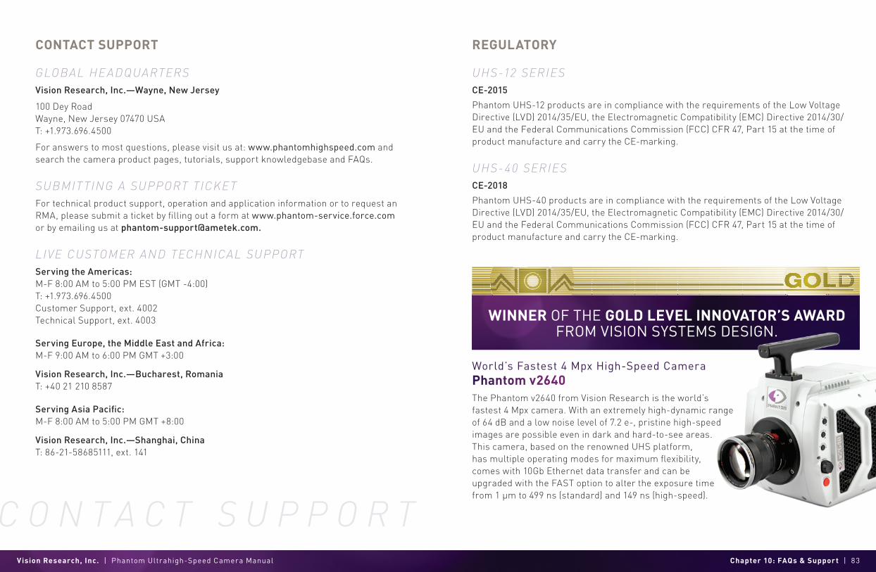
Vision Research, Inc. | Phantom Ultrahigh-Speed Camera Manual Chapter 10: FAQs & Support | 83
C O N T A C T S U P P O R T
CONTACT SUPPORT
GLOBAL HE ADQUARTERSVision Research, Inc.—Wayne, New Jersey
100 Dey RoadWayne, New Jersey 07470 USAT: +1.973.696.4500
For answers to most questions, please visit us at: www.phantomhighspeed.com and search the camera product pages, tutorials, support knowledgebase and FAQs.
SUBMIT TING A SUPPORT TICKETFor technical product support, operation and application information or to request an RMA, please submit a ticket by filling out a form at www.phantom-service.force.com or by emailing us at [email protected].
LIVE CUSTOMER AND TECHNICAL SUPPORTServing the Americas:M-F 8:00 AM to 5:00 PM EST (GMT -4:00)T: +1.973.696.4500Customer Support, ext. 4002 Technical Support, ext. 4003
Serving Europe, the Middle East and Africa:M-F 9:00 AM to 6:00 PM GMT +3:00
Vision Research, Inc.—Bucharest, RomaniaT: +40 21 210 8587
Serving Asia Pacific:M-F 8:00 AM to 5:00 PM GMT +8:00
Vision Research, Inc.—Shanghai, ChinaT: 86-21-58685111, ext. 141
REGULATORY
UHS-12 SERIESCE-2015
Phantom UHS-12 products are in compliance with the requirements of the Low Voltage Directive (LVD) 2014/35/EU, the Electromagnetic Compatibility (EMC) Directive 2014/30/EU and the Federal Communications Commission (FCC) CFR 47, Part 15 at the time of product manufacture and carry the CE-marking.
UHS-40 SERIESCE-2018
Phantom UHS-40 products are in compliance with the requirements of the Low Voltage Directive (LVD) 2014/35/EU, the Electromagnetic Compatibility (EMC) Directive 2014/30/EU and the Federal Communications Commission (FCC) CFR 47, Part 15 at the time of product manufacture and carry the CE-marking.
World’s Fastest 4 Mpx High-Speed Camera Phantom v2640The Phantom v2640 from Vision Research is the world’s fastest 4 Mpx camera. With an extremely high-dynamic range of 64 dB and a low noise level of 7.2 e-, pristine high-speed images are possible even in dark and hard-to-see areas. This camera, based on the renowned UHS platform, has multiple operating modes for maximum flexibility, comes with 10Gb Ethernet data transfer and can be upgraded with the FAST option to alter the exposure time from 1 µm to 499 ns (standard) and 149 ns (high-speed).
WINNER OF THE GOLD LEVEL INNOVATOR’S AWARD FROM VISION SYSTEMS DESIGN.

Chapter 2: Connectors | 85Vision Research, Inc. | Phantom Ultrahigh-Speed Camera Manual
CHANGE LOG
UHS Manual Rev 5
- Updated to reflect the retire of the v1212 and v1612 - Correction of pin depiction on Power port (page 72)- Clarified connector part numbers for:
Range Data connector; GPS connector; Power connector; Remote connector
Written and produced by the Marketing Department at Vision Research.
The contents of this manual are subject to change without notification.
PN: ZDOC-64110-MA-0001 Rev 5Last Updated: July 2021
P H A N T O M H I G H S P E E D . C O M
WWW.PHANTOMHIGHSPEED.COM
100 Dey RoadWayne, NJ 07470 USA+1.973.696.4500