V160 Stirling Engine_for a Total Energy System
7
-
Upload
casus-belli -
Category
Documents
-
view
43 -
download
3
Transcript of V160 Stirling Engine_for a Total Energy System
V160 STIRLING ENGINE ...for a Total Energy System.
Lennart Johansson JanAlpkvist William B. Lampert, III Lars Gimstedt Stirling Power Systems Roland Altin Ann Arbor, Michigan FFV
Linkoping, Sweden
ABSTRACT The Stirling Engine, an early concept in terms of modern technological development opens up new horizons and of-fers a fresh new approach for the future. The new power source meets the requirements for a fuel-hungry and en-vironmentally conscious world. Modern technology has made the Stirling Engine an attractive alternative to the internal combustion engine. The engine was designed to fill a need for a small, quiet, clean, multifuel powerplant. To meet the needs, and wide variety of new applications of the 1980's and beyond, the Stirling Engine is the ideal powerplant.
INTRODUCTION The modern Stirling-Cycle Engine is one which can meet today's growing demands on power sources for many appli-cations. In addition to meeting this demand Stirling Engines can provide:
• Multifuel Capability • Low Maintenance • Long Life • Clean Exhaust • Low Fuel Consumption • Low Noise • Low Vibration • Rejected Heat Concentrated in Engine Coolant
With this unique combination of attributes, the Stirling Engine has many potential applications. A Stirling Engine powered Total Energy System (TES) is only one example.
APPLICATIONS The application of interest is for a small Total Energy System. Such an application requires a 10 to 20 hp power source which will provide living environment comfort and conveni-ence without the noise, vibration, exhaust odor, high mainte-nance, or low reliability often associated with alternative power sources. Recreational applications such as recrea-tional vehicles, marine, and remote cottages are examples. Residential and light commercial applications are examples which require low fuel consumption in addition to providing living environment comfort and convenience.
The Stirling Engine's attributes make it a prime candidate for many other applications as well. For example, because of its multifuel capability it is well suited for applications in the petroleum, natural gas, and associated pipeline industries, for agricultural and general industrial applications where suitable burnable waste materials are available, and for ap-plications where solar energy is abundant. Because of its quiet operation the Stirling Engine could be used for military tactical generator sets and, with its clean exhaust, it has potential for underground mining applications. These are but a few of the many applications which can benefit from the Stirling Engine's unique combination of attributes.
2
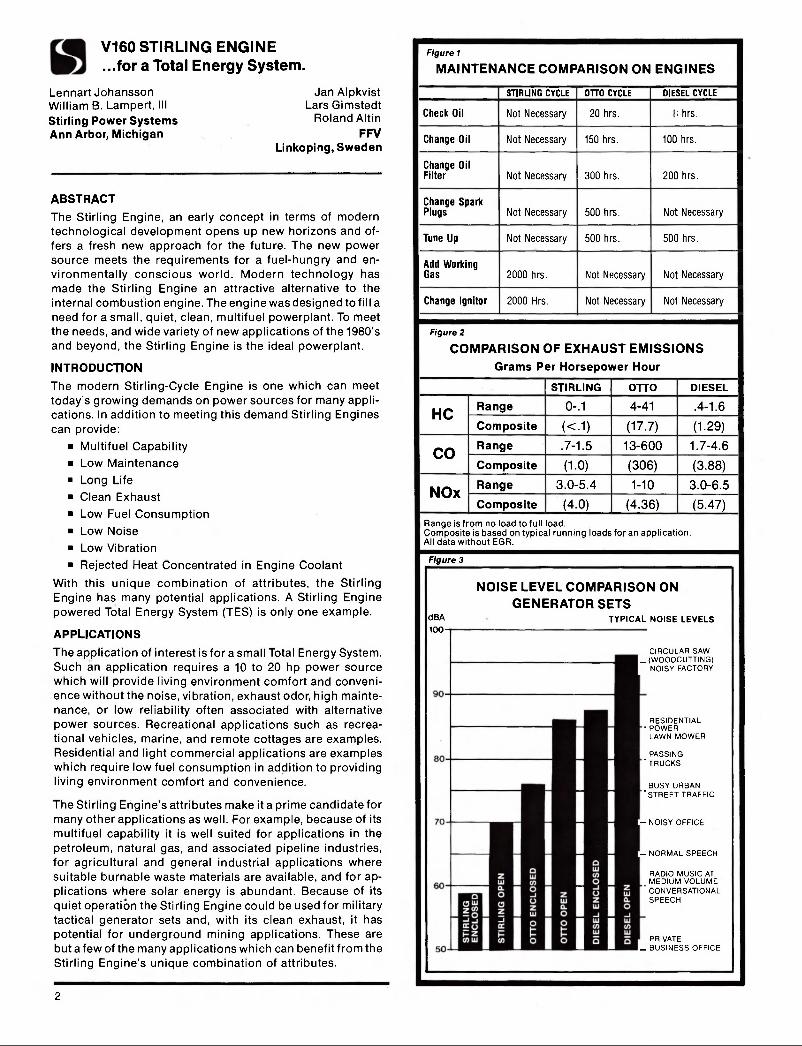
Figure 1
MAINTENANCE COMPARISON ON ENGINES
STIRLING CYCLE OTTO CYCLE DIESEL CYCLE
Check Oil Not Necessary 20 hrs. I hrs.
Change Oil Not Necessary 150 hrs. 100 hrs.
Change Oil Filter Not Necessary 300 hrs. 200 hrs.
Change Spark Plugs Not Necessary 500 hrs. Not Necessary
Tune Up Not Necessary 500 hrs. 500 hrs.
Add Working Gas 2000 hrs. Not Necessary Not Necessary
Change Ignitor 2000 Hrs. Not Necessary Not Necessary
Figure 2
COMPARISON OF EXHAUST EMISSIONS Grams Per Horsepower Hour
STIRLING OTTO DIESEL
HC Range 0-.1 4-41 .4-1.6 HC Composite « . 1 ) (17.7) (1.29)
CO Range .7-1.5 13-600 1.7-4.6 CO Composite (1-0) (306) (3.88)
NOx Range 3.0-5.4 1-10 3.0-6.5 NOx Composite (4.0) (4.36) (5.47)
Range is from no load to full load. Composite is based on typical running loads for an application. All data without EGR.
Figure 3
dBA 100-
NOISE LEVEL COMPARISON ON GENERATOR SETS
TYPICAL NOISE LEVELS
CIRCULAR SAW L (WOODCUTTING) I NOISY FACTORY
RESIDENTIAL • POWER
LAWN MOWER
PASSING "TRUCKS
BUSY URBAN "STREET TRAFFIC
- NOISY OFFICE
- NORMAL SPEECH
RADIO MUSIC AT MEDIUM VOLUME
' CONVERSATIONAL SPEECH
PRIVATE L BUSINESS OFFICE

MODERN STIRLING-CYCLE ENGINE ATTRIBUTES Multifuel Modern Stirling-Cycle Engines are closed cycle machines in which continuously alternating heating and cooling cause the enclosed working gas to expand and contract, thus pro-viding mechanical power. Heat is provided externally, usually by burning combustible materials of sufficient heating value (although solar heating is also possible). Because combus-tion takes place outside the engine cylinders, a Stirling En-gine can be adapted to burn a variety of fuel sources.
Low Maintenance and Long Life Furthermore, because combustion is external, combustion products do not contact the pistons, cylinders, or lubricating oil. This promotes longer engine life, low maintenance and minimal oil consumption. Compared to Otto-Cycle and Di-esel engines of similar size, the Stirling Engine reported herein, called the V160, requires less than half the mainte-nance and is at least equal to or better than the diesel in life. (Figure 1)
Low Exhaust Emissions Continuous external combustion permits good combustion control. This results in very low exhaust emissions without special exhaust treatment. The V160 Stirling Engine is lower in all emissions categories than comparable Otto-Cycle and Diesel engines (particularly regarding unburned hydro-carbons and carbon monoxide.) (Figure 2)
Low Fuel Consumption The ideal Stirling thermodynamic cycle has the same theoret-ical efficiency as the Carnot cycle. This, in addition to good control of the external combustion, results in high efficiency and, thus, low fuel consumption. The V160 Stirling Engine was designed for higher reliability and (ower manufacturing cost at the expense of a somewhat lower efficiency than Stirling Engines can achieve. Even so, the V160 is 15 to 50% lower in fuel consumption than a comparable Otto-Cycle engine over the load range and can be slightly better than diesel at part loads.
Low Noise and Vibration Within the closed Stirling cycle pressure variations of the working gas follow an almost sinusoidal curve. These smooth pressure variations result in low noise and vibration levels. Tests show that the V160 is several times lower in noise and vibration than comparable Otto-cycle and Diesel en-gines. (Figure 3)
Concentration of Rejected Heat Compared to internal combustion engines, the Stirling En-gine rejects the majority of unused heat in the engine cool-ant. In the Total Energy System application this rejected heat provides living environment heating whenever required.
The Stirling-Cycle Engine, with its unique combination of attributes, promises to meet the needs for a clean, quiet, economical power source in numerous applications. It is particularly well suited for a Total Energy System.
THE V160 STIRLING-CYCLE ENGINE The Stirling-Cycle Engine developed for the above-mentioned applications is called the V160. (Figure 4) This refers to the engine configuration (Figure 5), which is a two cylinder, V-type, 90 degree design with a 160 cubic centimeter swept volume (68mm bore, 44mm stroke). This design con-figuration maximizes the market potential by setting high
Figure 4 Stirling Engine
Figure S Stirling Engine (Cross Section)
3
priorities on the attributes of high engine reliability and minimum cost. Where design compromises have been necessary, they have been weighted in favor of these two attributes. The most significant compromises are that: 1. A modest reduction in potential efficiency is accepted in
choosing a simple single-acting Stirling-cycle design over alternative double-acting designs in order to reduce cost and complexity of this small Stirling Engine.
2. A reduction in power-to-weight ratio is accepted in op-timizing the V160 for 1800 rpm operation and 8KW power output in order to increase reliability. (The mechanical parts of the V160 have been designed for and will deliver 15KW at 3600 rpm. The complete V160 could be reop-timized to a high efficiency at this speed as well but the reliability could be reduced).
3. A slight reduction in power and efficiency also is accepted in optimizing the V160 for helium as the working gas rather than accepting the added costs and reduced relia-bility associated with hydrogen as the working gas. (The V160 could be reoptimized for hydrogen once materials and seals have been developed to achieve costs and relia-bility equivalent to the present V160 with helium working gas).
In summary, the V160 design philosophy is to achieve maximum market potential by developing a highly reliable, inexpensive small Stirling-Cycle Engine. The resulting basic design is a single-acting, V-type engine with a swept volume of 160 cc and helium working gas which operates at 1800 rpm and delivers 8KW. This design philosophy carries through, as well, to the design of each major engine subsystem, i.e.,
• Drive Unit • Heating System • Power Control • Air/Fuel System • Electronics and Electrical • Enclosure
THE V160 SUBSYSTEMS Drive Unit The Stirling Engine driving mechanism consists of:
• A cylinder block, cast nodular iron • One crankshaft • Two connecting rods • Two crossheads with piston rods • Two piston rod sealing units • Two pistons with piston rings • Compressor plunger with piston rings • Lubricating oil pump • Main bearing support • Flywheel • Flywheel cover • Engine mountings • Starting motor
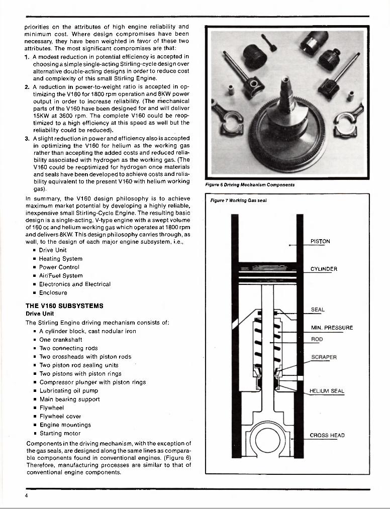
Components in the driving mechanism, with the exception of the gas seals, are designed along the same lines as compara-ble components found in conventional engines. (Figure 6) Therefore, manufacturing processes are similar to that of conventional engine components.
Figure 6 Driving Mechanism Components
Figure 7 Working Gas seal
PISTON
CYLINDER
MIN. PRESSURE
HELIUM SEAL
CROSS HEAD
4
Two identical gas seals, located on the piston rods (Figure 7), prevent gas from leaking into the crankcase, and conversely prevent oil from entering the working gas portion of the cycle. Seals developed for this engine are sliding type seals. A sealing ring compressed around the piston rod serves as the main seal. Above the main seal an oil scraper ring re-moves oil adhering to the piston rod. A cap in the upper portion of the seal serves as the first stage in the sealing system.
Finally, the drive unit block is designed with liquid coolant jackets to cool temperature sensitive drive parts and the working gas on its way to the compression cylinder. The, engine cooling system was designed for a 50/50 coolant mixture of water and glycol with a maximum mean cooling temperature of 70°C.
A coolant pump is mounted on the flywheel cover and is belt driven from the flywheel. The pump is a conventional cen-trifugal type pump and functions as a circulating pump for the coolant. The engine heat can be rejected from the coolant to the environmental heating system or to outside air through a radiator. The radiator can be mounted remotely or on the engine with a belt driven radiator fan.
Heating System The engine heating system includes the following: • PRIMARY HEAT EXCHANGER — consists of heating tubes
connected by ducts to the expansion cylinder and re-generator housing. Heater tubes contain helium working gas and are surrounded by a concentric mantle.
• REGENERATOR — located in a housing on top of the gas cooler.
• GAS COOLER — located in the cylinder block housing.
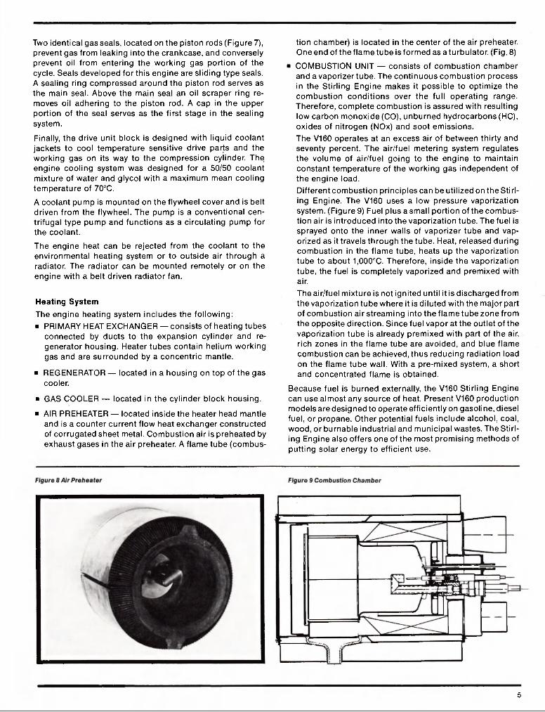
• AIR PREHEATER — located inside the heater head mantle and is a counter current flow heat exchanger constructed of corrugated sheet metal. Combustion air is preheated by exhaust gases in the air preheater. A flame tube (combus-
tion chamber) is located in the center of the air preheater. One end of the flame tube is formed as a tu rbulator. (Fig. 8)
• COMBUSTION UNIT — consists of combustion chamber and a vaporizer tube. The continuous combustion process in the Stirling Engine makes it possible to optimize the combustion conditions over the full operating range. Therefore, complete combustion is assured with resulting low carbon monoxide (CO), unburned hydrocarbons (HC), oxides of nitrogen (NOx) and soot emissions. The V160 operates at an excess air of between thirty and seventy percent. The air/fuel metering system regulates the volume of air/fuel going to the engine to maintain constant temperature of the working gas independent of the engine load. Different combustion principles can be utilized on the Stirl-ing Engine. The V160 uses a low pressure vaporization system. (Figure 9) Fuel plus a small portion of the combus-tion air is introduced into the vaporization tube. The fuel is sprayed onto the inner walls of vaporizer tube and vap-orized as it travels through the tube. Heat, released during combustion in the flame tube, heats up the vaporization tube to about 1,000°C. Therefore, inside the vaporization tube, the fuel is completely vaporized and premixed with air. The air/fuel mixture is not ignited until it is discharged from the vaporization tube where it is diluted with the major part of combustion air streaming into the flame tube zone from the opposite direction. Since fuel vapor at the outlet of the vaporization tube is already premixed with part of the air, rich zones in the flame tube are avoided, and blue flame combustion can be achieved, thus reducing radiation load on the flame tube wall. With a pre-mixed system, a short and concentrated flame is obtained.
Because fuel is burned externally, the V160 Stirling Engine can use almost any source of heat. Present V160 production models are designed to operate efficiently on gasoline, diesel fuel, or propane. Other potential fuels include alcohol, coal, wood, or burnable industrial and municipal wastes. The Stirl-ing Engine also offers one of the most promising methods of putting solar energy to efficient use.
5
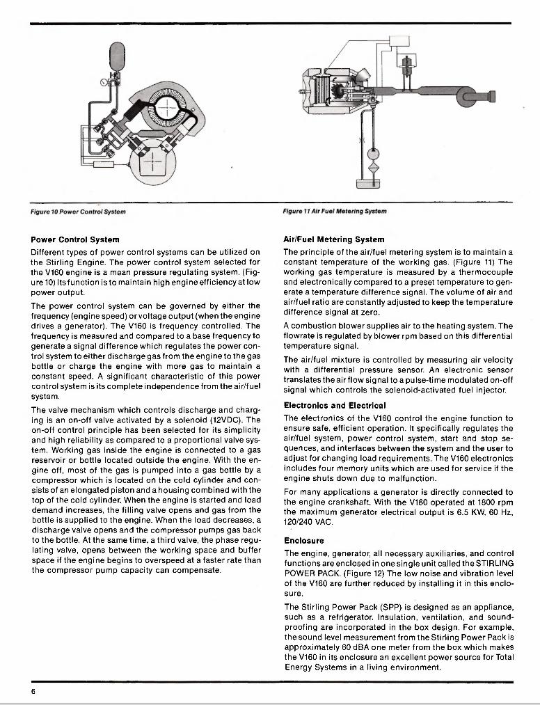
Power Control System Different types of power control systems can be utilized on the Stirling Engine. The power control system selected for the V160 engine is a mean pressure regulating system. (Fig-ure 10) Its function is to maintain high engine efficiency at low power output.
The power control system can be governed by either the frequency (engine speed) or voltage output (when the engine drives a generator). The V160 is frequency controlled. The frequency is measured and compared to a base frequency to generate a signal difference which regulates the power con-trol system to either discharge gas from the engine to the gas bottle or charge the engine with more gas to maintain a constant speed. A significant characteristic of this power control system is its complete independence from the air/fuel system.
The valve mechanism which controls discharge and charg-ing is an on-off valve activated by a solenoid (12VDC). The on-off control principle has been selected for its simplicity and high reliability as compared to a proportional valve sys-tem. Working gas inside the engine is connected to a gas reservoir or bottle located outside the engine. With the en-gine off, most of the gas is pumped into a gas bottle by a compressor which is located on the cold cylinder and con-sists of an elongated piston and a housing combined with the top of the cold cylinder. When the engine is started and load demand increases, the filling valve opens and gas from the bottle is supplied to the engine. When the load decreases, a discharge valve opens and the compressor pumps gas back to the bottle. At the same time, a third valve, the phase regu-lating valve, opens between the working space and buffer space if the engine begins to overspeed at a faster rate than the compressor pump capacity can compensate.
Air/Fuel Metering System The principle of the air/fuel metering system is to maintain a constant temperature of the working gas. (Figure 11) The working gas temperature is measured by a thermocouple and electronically compared to a preset temperature to gen-erate a temperature difference signal. The volume of air and air/fuel ratio are constantly adjusted to keep the temperature difference signal at zero.
A combustion blower supplies air to the heating system. The flowrate is regulated by blower rpm based on this differential temperature signal.
The air/fuel mixture is controlled by measuring air velocity with a differential pressure sensor. An electronic sensor translates the air flow signal to a pulse-time modulated on-off signal which controls the solenoid-activated fuel injector.
Electronics and Electrical The electronics of the V160 control the engine function to ensure safe, efficient operation. It specifically regulates the air/fuel system, power control system, start and stop se-quences, and interfaces between the system and the user to adjust for changing load requirements. The V160 electronics includes four memory units which are used for service if the engine shuts down due to malfunction.
For many applications a generator is directly connected to the engine crankshaft. With the V160 operated at 1800 rpm the maximum generator electrical output is 6.5 KW, 60 Hz, 120/240 VAC.
Enclosure The engine, generator, all necessary auxiliaries, and control functions are enclosed in one single unit called the STIRLING POWER PACK. (Figure 12) The low noise and vibration level of the V160 are further reduced by installing it in this enclo-sure.
The Stirling Power Pack (SPP) is designed as an appliance, such as a refrigerator. Insulation, ventilation, and sound-proofing are incorporated in the box design. For example, the sound level measurement from the Stirling Power Pack is approximately 60 dBA one meter from the box which makes the V160 in its enclosure an excellent power source for Total Energy Systems in a living environment.
6

Figure 14 ELECTRICAL CONTROL CENTER
ELECTRICAL CONTROL CENTER Energy for all electrical appliances, heating, and air condi-tioning is provided by the SPP. Therefore, it is logical to develop an electrical control center which simplifies the in-stallation and operation of appliances. The electrical center is a demand system which provides a signal to operate the SPP. (Figure 14)
The electrical center is connected to and monitors two power sources — Stirling Power Pack and land line connection. Switching between Stirling and land line is fully automatic. When electrical power requirements inside the coach exceed available land line power, the system automatically switches to the supply power from the SPP.
All necessary circuit breakers for the 120/240VAC and 12VDC are attached to the electrical control center which simplifies installation of appliances. Furthermore, a battery charger has been built into the electrical control center and provides necessary charging capacity and low power 12VDC. The charger has a maximum capacity of 60 amps. The control and sensing functions for the battery charger also are located in the electrical control center. When the batteries call for charging, the system (Stirling or land line) automatically en-gages the charger.
For further information on the Stirling Engine contact:
STIRLING POWER SYSTEMS P.O. BOX 1187 7101 JACKSON ROAD ANN ARBOR, Ml 48106 Tel: (313) 665-6767 Telex: 810-223-6010
Figure 15 CONTROL PANEL
CONTROL PANEL One of the primary objectives in the development of this system was SIMPLICITY OF OPERATION. Therefore, a con-trol panel was designed with three push buttons to activate the system. (Figure 15) These activate the automatic, Stirling, or land line functions. The control panel has six readout functions to indicate failure or service needs and six to indi-cate operating system loads. Function of the controls can be inspected in the momentary check position of the switch. Once the control panel has been switched to automatic mode, start-up, operation, and shut-down are automatically controlled. Service needs also are automatically identified by system on the control panel.
SUMMARY The Stirling Engine is a thoroughly researched, carefully designed and exhaustively tested product designed by FFV to meet the needs of the 1980's and beyond, for a small, quiet, clean, multifuel, powerplant. Potential uses of the Stirling Engine are aflmost limitless and have been tested in au-tomobiles and boats. The current Stirling V160 engine can be adapted to a variety of applications such as a Total Energy System (TES) for motorhomes, yachts, and cottages... pro-viding efficient homelike comfort and convenience. Other applications include generator sets, military field operations, and hybrid vehicles.
The Stirling Engine will be available as a bare engine or Stirling Power Pack incorporating a modular concept to meet various customer requirements.
8