
V. Stamati 1, G. Antonopoulos , Ph. Azariadis and I. Fudos · Technical Report TR-2011-4, Computer...
38
Technical Report TR-2011-4, Computer Science Department, University of Ioannina Page 1 ReJCAD: A Feature-based CAD System for Reconstructing Traditional Filigree Jewelry V. Stamati 1 , G. Antonopoulos 1 , Ph. Azariadis 2 and I. Fudos 1 Abstract This paper presents a novel approach to reconstructing traditional filigree jewelry. Our method aims at producing an editable CAD representation that can accurately capture the original design and be capable of re-parameterization and modification prior to manufacturing (for example to insert custom designs and abide to free-form artistic alterations). To achieve this, we have developed robust and accurate representations of patterns, used in the design of such jewelry, based on spirals, circular and elliptic arcs, curve segments and braids of various types; all optimized by fairness criteria for aesthetic purposes. We have also built a library of parametric, constraint-based, manufacturable solid patterns that occur frequently in filigree jewelry. For the purposes of this work, a suite of software tools called ReJCAD has been developed, that is able to process a highly accurate point-cloud of jewelry pieces and to detect features which are fitted by the primitives of the pattern library through user interaction. The point cloud, in the current framework, guides the assembling of all patterns into one robust manufacturable solid piece. We demonstrate the unique capabilities of ReJCAD by reconstructing a filigree brooch part commonly used in late 19th century at northwestern Greece. Keywords: filigree jewelry, parametric design, jewelry patterns, feature-based reconstruction, re- engineering 1 Introduction Computer Aided Design (CAD) systems are widely used in most industries and are increasingly used in jewelry manufacturing [1, 2]. While manual design of jewelry is still in wide use, this approach is both cumbersome and time consuming when compared to designing using 3D CAD systems. Editing and redesigning are feasible in a 3D CAD environment, as long as they are supported by parametric and constraint-based techniques [3, 4]. 3D rendering helps the artist to detect parts of the model that are unsatisfactory [5]. In addition, it is possible to redesign based on customer feedback after browsing the first version. Generally, current feature-based systems include various tools to assist in designing a piece of jewelry, including constraints, transformations, libraries of jewelry parts and other solid patterns such as cut stones and gems. Despite the effectiveness of current 3D CAD systems for jewelry, there are categories of jewelry that cannot be reconstructed even with modern CAD systems. Examples of such types of jewelry are 1 Department of Computer Science, University of Ioannina, Greece 2 Department of Product and Systems Design Engineering, University of the Aegean, Greece
Transcript of V. Stamati 1, G. Antonopoulos , Ph. Azariadis and I. Fudos · Technical Report TR-2011-4, Computer...

Technical Report TR-2011-4, Computer Science Department, University of Ioannina Page 1
ReJCAD: A Feature-based CAD System for Reconstructing Traditional Filigree Jewelry
V. Stamati1, G. Antonopoulos
1, Ph. Azariadis
2 and I. Fudos
1
Abstract
This paper presents a novel approach to reconstructing traditional filigree jewelry. Our method aims at
producing an editable CAD representation that can accurately capture the original design and be
capable of re-parameterization and modification prior to manufacturing (for example to insert custom
designs and abide to free-form artistic alterations). To achieve this, we have developed robust and
accurate representations of patterns, used in the design of such jewelry, based on spirals, circular and
elliptic arcs, curve segments and braids of various types; all optimized by fairness criteria for aesthetic
purposes. We have also built a library of parametric, constraint-based, manufacturable solid patterns
that occur frequently in filigree jewelry. For the purposes of this work, a suite of software tools called
ReJCAD has been developed, that is able to process a highly accurate point-cloud of jewelry pieces
and to detect features which are fitted by the primitives of the pattern library through user interaction.
The point cloud, in the current framework, guides the assembling of all patterns into one robust
manufacturable solid piece. We demonstrate the unique capabilities of ReJCAD by reconstructing a
filigree brooch part commonly used in late 19th century at northwestern Greece.
Keywords: filigree jewelry, parametric design, jewelry patterns, feature-based reconstruction, re-
engineering
1 Introduction
Computer Aided Design (CAD) systems are widely used in most industries and are increasingly used
in jewelry manufacturing [1, 2]. While manual design of jewelry is still in wide use, this approach is
both cumbersome and time consuming when compared to designing using 3D CAD systems.
Editing and redesigning are feasible in a 3D CAD environment, as long as they are supported by
parametric and constraint-based techniques [3, 4]. 3D rendering helps the artist to detect parts of the
model that are unsatisfactory [5]. In addition, it is possible to redesign based on customer feedback
after browsing the first version. Generally, current feature-based systems include various tools to assist
in designing a piece of jewelry, including constraints, transformations, libraries of jewelry parts and
other solid patterns such as cut stones and gems.
Despite the effectiveness of current 3D CAD systems for jewelry, there are categories of jewelry that
cannot be reconstructed even with modern CAD systems. Examples of such types of jewelry are
1 Department of Computer Science, University of Ioannina, Greece 2 Department of Product and Systems Design Engineering, University of the Aegean, Greece

Technical Report TR-2011-4, Computer Science Department, University of Ioannina
traditional pierced jewelry, filigree jewelry and modern jewelry of
made using a technique of twisting,
and silver) to create a lace-like effect of pierced jewelry
with precious stones, crystals or glasses to create both jewelry and non
forms of jewelry produced in filigree are earrings, bracelets, brooches, pendants, chains, necklaces and
buttons.
Findings in the Valley of the Kings
Egyptians. Wires of variable diameter were often used either to decorate precious metal surfaces or to
craft an entire jewelry piece. From Egypt the filigree technique spread to ancient Greece and Europe
and reached Persia and India [9]. In Tibet it was extensively use
traditional ga'u pendants which the Tibetans used as amulets or charms or credentials of authority
Figure 2 portraits the use of the filigree technique in such jewels.
India still remains a massive producer of filigree based jewelry.
Filigree is a technique that produces impressively elaborate artifacts, which combine elegance with the
aura of tradition. It became widespread, not only due to its elaborate and yet delicate results, but also
because it allows for the creation of maximum
(a)
Figure 2. Silver ga’u ornamented with (a
, Computer Science Department, University of Ioannina
igree jewelry and modern jewelry of free-form design.
twisting, bending, wrapping and braiding plain precious metal
like effect of pierced jewelry (Figure 1). The metalwork is often combined
with precious stones, crystals or glasses to create both jewelry and non-jewelry artifacts. Standard
jewelry produced in filigree are earrings, bracelets, brooches, pendants, chains, necklaces and
Figure 1. A filigree brooch.
Findings in the Valley of the Kings [8] suggest that this technique was first used by the an
Egyptians. Wires of variable diameter were often used either to decorate precious metal surfaces or to
From Egypt the filigree technique spread to ancient Greece and Europe
. In Tibet it was extensively used to decorate the inner parts of the
traditional ga'u pendants which the Tibetans used as amulets or charms or credentials of authority
the filigree technique in such jewels. The filigree technique flourished and
India still remains a massive producer of filigree based jewelry.
Filigree is a technique that produces impressively elaborate artifacts, which combine elegance with the
aura of tradition. It became widespread, not only due to its elaborate and yet delicate results, but also
because it allows for the creation of maximum size objects by consumption of a minimal amount of
(b)
. Silver ga’u ornamented with (a) gold, (b) silver filigree [9], and (c) detail
necklace [9].
Page 2
design. Filigree jewelry is
precious metal wires (gold
The metalwork is often combined
jewelry artifacts. Standard
jewelry produced in filigree are earrings, bracelets, brooches, pendants, chains, necklaces and
technique was first used by the ancient
Egyptians. Wires of variable diameter were often used either to decorate precious metal surfaces or to
From Egypt the filigree technique spread to ancient Greece and Europe
d to decorate the inner parts of the
traditional ga'u pendants which the Tibetans used as amulets or charms or credentials of authority [9].
The filigree technique flourished and
Filigree is a technique that produces impressively elaborate artifacts, which combine elegance with the
aura of tradition. It became widespread, not only due to its elaborate and yet delicate results, but also
size objects by consumption of a minimal amount of
(c)
, and (c) detail of a golden filigree

Technical Report TR-2011-4, Computer Science Department, University of Ioannina Page 3
precious metal. However it is very delicate, tedious and time-consuming, properties which have forced
local Mediterranean craftsmen to refrain from its use. This raised the need for a procedure that would
diminish the time consumed and remove the bulk of the labor of this technique.
In this paper, we present a novel approach to reconstructing, creating, and customizing jewelry of
filigree craftsmanship (Figure 1). A suite of CAD tools called as ReJCAD has been developed
providing the means to the end user to digitally reconstruct, personalize and manufacture filigree-type
jewelry using parametric and feature-based techniques. More specifically, this paper makes the
following technical contributions:
• Introduces a representation scheme for modeling filigree patterns using elliptical arcs, Bezier
segments, spirals and other curve segments. Geometric constraints are imposed on the model in the
underlying filigree design library to provide the necessary robustness, editability, and aesthetic
conformity to traditional design patterns.
• Describes a novel approach to modeling braids using rational Bezier curve segments which yields
an aesthetically improved class of braids.
• Presents a partially automated re-engineering process that aids the reconstruction of a CAD model
of traditional filigree jewelry using information derived from a point cloud acquired by high
precision 3D scanning.
The remainder of this paper is structured as follows. Section 2 summarizes the current state of art on
the open problems that have been tackled in this work. Section 3 presents the proposed classification
of parametric constraint-based patterns for creating editable 3D models of filigree jewelry.
Furthermore, it presents a new approach to modeling braids of strands using rational Bezier curves.
Section 4 describes the process of re-engineering and reconstructing filigree jewelry pieces, whereas
Section 5 presents evaluation results: an example case, a usability evaluation and examples of actual
manufactured jwelry. Finally, Section 6 offers conclusions.
2 Related Work
CAD tools are being used more and more in artistic and aesthetic applications. In these applications
the aim is not only to realize certain geometries and patterns but a main concern is the overall aesthetic
result. Examples serving this purpose are presented in [10, 11], where parametric sculpture generators
are implemented to create and modify artifacts belonging to certain conceptual families, and to
evaluate the final aesthetic result. In [12] an application concerning kinetic art, i.e., art that involves
movement, is presented. A system is proposed for designing original kinetic art objects where a 3D
Technical Report TR-2011-4, Computer Science Department, University of Ioannina Page 4
geometric-modeling interface and a rigid-body simulation are combined. A survey on CAD methods
used in another aspect of artistic expression, garment design, is provided in [13].
Jewelry design and construction is another example of combining CAD tools and aesthetics. Various
commercial software packages have been developed for designing and creating CAD jewelry models
such as JewelCAD [14], Rhino3D [15], ArtCAM JewelSmith/Delcam Designer [16], Matrix 3D
Jewelry Design Software [17] and 3Design CAD [18]. Most of these systems provide some form of
parametric and feature-based capabilities, graphical interfaces with excellent rendering capabilities,
built-in libraries focused on jewelry design that include different piece settings, cut gems and stones,
and advanced feature-based design tools. Some systems provide advanced functionality, such as
Matrix [17], which offers the use of builders for recording design steps and for defining parameter
values for parts to be used in the process. Also, the majority of these systems have the capability of
exporting models to rapid prototyping machines. All of these systems provide various tools for making
jewelry design a simpler and less time-consuming process.
These software packages are convenient for designing and creating various forms of generic style
jewelry. However, none of these systems is appropriate for designing and creating editable CAD
models of jewelry of a particular craftsmanship, such as filigree jewelry. In particular, for constructing
this type of jewelry, where the fine aesthetic result is achieved through twisting, bending and
combining wire strands to create complex designs, a system is required that provides the capability to:
i) create very accurate and robust solid models ready for reproduction, ii) create parametric models of
filigree jewelry that can be used for custom design and redesign and iii) incorporate filigree designs
into a solid model corresponding to a ring, bracelet, necklace, etc. In most commercial CAD systems
for jewelry, designing is performed manually using various tools and usually the design steps cannot
be programmed to be executed automatically and accurately. This means that each different piece of
pierced jewelry would have to be created basically from the beginning by hand which does not
conform to the requirement of redesign capability. Editing is then usually achieved through history
rollback, by returning to a prior design state of the model and applying modifications to the model.
Another CAD approach to designing and producing jewelry of a particular craftsmanship is
ByzantineCAD [6]. ByzantineCAD is an automated, parametric CAD system for designing and
producing pierced Byzantine jewelry where the user-designer sets some parameter values and
ByzantineCAD creates the jewelry model that corresponds to the specified values. This provides the
designer with the capacity to rapidly create custom-designed jewelry, based on the preferences of the
customers. ByzantineCAD introduces a feature-based and voxel-based approach to designing jewelry,
through the definition of elementary structural elements with specific attributes that are used as
building blocks to construct complex pierced designs. Modern free-form jewelry can only be partially

Technical Report TR-2011-4, Computer Science Department, University of Ioannina Page 5
described through predefined primitives and feature libraries, due to its abstract and artistic nature
which is often difficult to capture. It is usually created using curves (such as NURBS) and surface
modeling techniques. An alternative approach to reconstructing free-form artifacts is presented in [7].
A parametric approach to creating carved jewelry is also presented in [19]. Voxel elements are
constructed and combined to recreate jewelry depicting designs made from small carvings. This
system provides both design and rapid prototyping capabilities. In [20] a parametric feature based
jewelry modeler for designing and manufacturing Fret-worked bangles is presented. Fretwork designs
are encoded as features that are recurrently removed from stock-solid bangles. Finally, Kai et al [21]
developed a reverse engineering system for re-engineering rings. This method creates basic generic
models of the initial ring object. To manufacture the ring, the 3D model is transformed into a 2D
representation on which the engraving of the ring design will be performed. This method is appropriate
for creating blank generic models of rings that a designer will then use to create his/her own ring
model.
In general, editing parts of filigree designs in commercial jewelry design systems requires in depth
knowledge of feature-based design and solid modeling techniques. In contrast, our system offers an
easy, semi-automated procedure for creating and customizing jewelry featuring filigree designs. In our
system one defines the basic parameters that refer mostly to the appearance, size and content of the
final product and then the construction of the specified model is carried out by the system. By
parameterizing the process of creating filigree jewelry, it is easy to modify characteristics of the
jewelry such as the size and the designs represented. Furthermore, designing a piece of filigree jewelry
using a traditional CAD system may lead to models with robustness problems, which are inappropriate
for manufacturing, creating therefore the need for repairing tools and techniques. The technique used
in our system leads to robust models that can be directly sent to rapid prototyping machines for
manufacturing without any further intervention or repair.
3 Identifying and Reconstructing Filigree Features
Through studying the design of a series of filigree made jewelry, particularly those made by local
craftsmen in northwest Greece, we have concluded that certain primordial patterns are being used
repeatedly in various combinations. Examples of filigree patterns are shown in Figure 3. By studying
the craftsmanship of filigree jewelry, a core set of patterns that are used as building blocks in a wide
range of filigree designs is identified.
In this Section, we first enumerate the characteristics of wire strands which are the building elements
of filigree jewelry. Then we describe common elementary features observed in filigree jewelry.

Technical Report TR-2011-4, Computer Science Department, University of Ioannina Page 6
Finally, we report on the composition of more complex designs that are commonly used in this type of
craftsmanship.
In our models wires are allowed to slightly overlap each other to enforce coherency. Wire overlapping
is considered critical for manufacturability (during both 3D printing and casting) and does not affect
the aesthetics of the final jewelry piece if it remains within reasonable bounds (i.e., just enough to
make the construction manufacturable and coherent). Experienced craftsmen and artists have
determined that the edges of the resulting jewelry piece are even sharper than the original piece
because of the gluing material used by the craftsmen in filigree jewelry. To have better control of the
design sharpness we provide a parameter that affects the thickness of all the wires involved in feature
construction by a small percentage (up to 10%± ).
Figure 3. Various design elements observed in filigree jewelry [9]
3.1 Wire Strands
The basic idea behind filigree craftsmanship is to twist and bend strands of wires to build complex
designs. Certain properties (parameters) stand out regarding the wires used to build and decorate a
filigree jewelry piece: wire strand geometry (thickness and length), the number of wire strands and the
technique of combining strands to create larger decorative and more complex strands. A simple wire
strand is modeled as a solid translational sweep of a circular-disk profile of radius wr along a defining
curve trajectory of length l . By altering the radius wr of the circular face and the length l of the
profile curve, we obtain different combinations of wire length and thickness. Multiple strands of wires
can be combined to create more complex ornamental wires by twisting them in the same direction,
braiding them, or combining them in an intersecting formation.
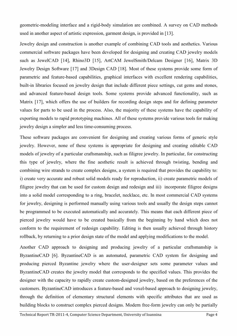
Twisted Wire Strands: It is a complex wire strand consisting of one or more twisted strands which
follow helical paths of the same direction (Figure 4). The equation describing the helical spiral curve is:
[ ]T( ) cos( ) sin( ) , t [0, ]C t r t r t ctθ θ ∞= + + ∈ , where r is the radius of the helix and c is the pitch
of the helix. Each strand is translated and placed such that the distance between the corresponding
helical paths of two adjacent strands is at least /d c n= , where n is the number of wire strands. The
Technical Report TR-2011-4, Computer Science Department, University of Ioannina Page 7
radius of each strand should be slightly larger than 2
d to achieve a small overlapping between adjacent
strands (Figure 4b).
The parametric surface representation of a twisting wire strand s can be derived by sweeping a circle
of radius wr on a helical path. Similarly we derive the representation of the surface of braids, teardrops
and other constructs made of 3D wires.
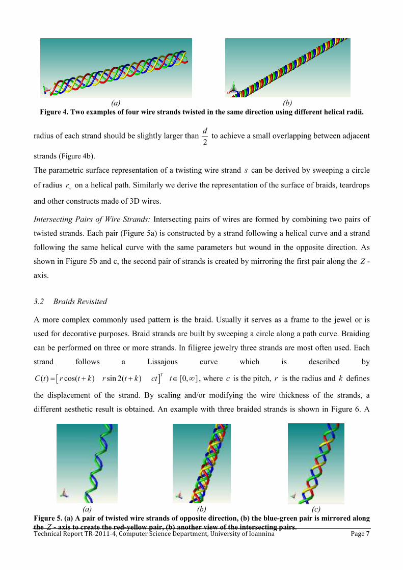
Intersecting Pairs of Wire Strands: Intersecting pairs of wires are formed by combining two pairs of
twisted strands. Each pair (Figure 5a) is constructed by a strand following a helical curve and a strand
following the same helical curve with the same parameters but wound in the opposite direction. As
shown in Figure 5b and c, the second pair of strands is created by mirroring the first pair along the Z -
axis.
3.2 Braids Revisited
A more complex commonly used pattern is the braid. Usually it serves as a frame to the jewel or is
used for decorative purposes. Braid strands are built by sweeping a circle along a path curve. Braiding
can be performed on three or more strands. In filigree jewelry three strands are most often used. Each
strand follows a Lissajous curve which is described by
[ ]( ) cos( ) sin 2( ) [0, ]T
C t r t k r t k ct t ∞= + + ∈ , where c is the pitch, r is the radius and k defines
the displacement of the strand. By scaling and/or modifying the wire thickness of the strands, a
different aesthetic result is obtained. An example with three braided strands is shown in Figure 6. A
(a) (b)
Figure 4. Two examples of four wire strands twisted in the same direction using different helical radii.
(a) (b) (c)
Figure 5. (a) A pair of twisted wire strands of opposite direction, (b) the blue-green pair is mirrored along
the Z - axis to create the red-yellow pair, (b) another view of the intersecting pairs.

Technical Report TR-2011-4, Computer Science Department, University of Ioannina Page 8
useful alternative to the Lissajous curve is outlined here by using rational Bezier segments to build
strands with improved fairness properties.
Figure 6. An example of braided strands.
A commonly used set of path curves is given by the sinusoidal parametric curve family described by
Eq.(1) [27], where n is the number of strands. In general, we can use alternative displacements for the
strand placement (besides the standard 2
in
π). Strand placement is important to ensure smooth intermix
of strands (i.e. strand touching with minimum overlapping). To safely avoid heavy strand overlapping
one may revert to approximate arc length parameterization in the expense of lower accuracy. This
approach may be used to ensure stable inter-strand distances by moving all strands by equal arc length
along the path curve. However, in practice it suffices to place the initial strand centers so as to achieve
a small overlap. The actual parametric description of the braid surface can be derived by sweeping a
circle along the curve path:
( ) 2 2cos sin 2( ) , [0, ], 0,1, , 1
T
iC t r i r i i nn
cn
π πθ θ θθ
= + + ∞ = − …ε (Eq. 1)
The above setting results in a representation with parameters: the radius r , the number n and the
placement of the strands, and the pitch c . However in jewelry design it is important to provide
aesthetically optimal braids. To this end, we present a sweep path route for building braid strands that
is more flexible as compared to the classic 3D extension of the simple Lissajous curve.
3.2.1 Revisiting Braids
We use cubic rational Bezier curves to realize braid strand path curves, a choice that offers a wider
range of parameters and essentially better aesthetic results. Our braid approach is a set of four such
curves, which are pair-wise symmetric. For cubic rational Bezier curves with control points ( ),m t jP and
weights ( ),m t jw with ( )m t being the curve index and j being the control point index, ( ) mod 4m t t= ,
0, ,3j = … , the position upon the curve at any given time t is given by:

Technical Report TR-2011-4, Computer Science Department, University of Ioannina Page 9
3 3
( ), ( ),0
3 3
( ),0
3( ) (1 ( ))
( )3
( ) (1 ( ))
( )
( ) ( ) , [0, ]
( )
j j
m t j m t jj
j j
m t jj
x i
i y i
i
t t t t P wj
CB t
t t t t wj
CB t k
C t CB t k t
c t k
−
=
−
=
− − −
=
− − −
+
= + ∈ ∞ +
∑
∑ (Eq. 2)
where ( ) CB t is the XY -plane projection of the sweep path curve, and i
k is the displacement that
corresponds to the i -th strand.
Figure 7 illustrates the construction of ( )CB t . The two pairs of symmetric curve segments that
contribute to the braid are depicted in red and blue. The control points are also depicted with their
indexing revealing the direction of movement along the curve.
Figure 7. Visualization of ( ) , [0,4]CB t tε .
Two main parameters that directly specify the control points 0,1 0,2 2,1 2,2, , , P P P P are the width and height
of the convex hull of the braid projection. To preserve horizontal and vertical symmetry we set
,0 ,3 1i iw w= = and
,1 ,2 .i iw w= This reduces the number of weight parameters for each braid to two.
Control points 0,3P and
1,1P are then set as follows (note that 0,3P and
1,0P are identical and 0,2P ,
0,3P ,
1,1 P , 2,2P are collinear) based on parameters a and β :
0,3 0,2 0,2 2,2|| || || ||P P a P P=− and
1,1 0,2 0,2 2,2|||| || ||P P P Pβ=− , where ( )1, 0,2
a β∈ . The rest of the control points are computed using the
horizontal and vertical symmetry of the curve segments.
3.2.2 Strand Placement
Braid strands should be placed so as to ensure slight overlap of the swept circles. First, one should
ensure that the braid strand centers do not collide. For an odd number n of strands we may just define
��,�=��,� ��,� ��,� ��,� ��,� = ��,� ��
��,� = ��,� ��,�
��,�
��,� = ��,� ��,�
��,�
��,�

Technical Report TR-2011-4, Computer Science Department, University of Ioannina Page 10
4ik i
n= , then it is easy to prove that there will be collision of the strand path curves. Indeed, the only
possible scenario that leads to a collision is for a strand center point to start from the opposite
symmetric location. For two locations to be anti-symmetric they need to have time-distance equal to 2.
So, for two strands ,i j with displacement ,i jk k with ,j i> the following equation must hold:
4 42 2( ) 0 2( )i j k i j k j i
k k+ = ⇔ + − = ⇔ = − which implies that k is some even number.
Likewise, for an even number of strands we have to enforce non-mirror symmetry between any pair of
strand centers. Figure 8 illustrates four braid strand route-paths projected on the XY -plane.
Figure 8. Strand movement scenario.
Figure 9. Determining strand thickness for the placement on the left by using mirroring and minimum
pair wise distance picking.
In practice an approach that works very well in determining the strand thickness is to derive the
minimum pair-wise distance D for the set of points that consists of the strand center points of the left-
side part and the symmetric center points of the right-side part (see Figure 9). Then we choose as
thickness a quantity slightly larger than 2
D. Note that D is the maximal minimum distance between
two strands since it corresponds to the tangent plane of the path curve being perpendicular to the XY -
plane.
3.2.3 Deriving Aesthetically Optimal Braids
By comparing the curvature values of our rational Bezier approach with those of the sinusoidal
approach we can adjust the parameters of the former to produce aesthetically different results.
�

Technical Report TR-2011-4, Computer Science Department, University of Ioannina
Figure 10. Rational Bezier curve mean curvature values
(a) Figure 11. (a) Rendering of braided strands created using (green) the sinusoid function and (red) rational
Bezier curves
The control points may be positioned so that the result will be as close to the shape of a sinusoid braid
as possible. Then we compute the curvature at each point on the rational Bezier curves. We consider
the mean of the curvature values within the specified ranges for both cur
two curves along with the corresponding sinusoidal part, since the rest are symmetric.
Figure 10 shows how the curvature of the rational Bezier braid progresses as the weights of the two
component curves increase. The wired plane represents the mean curvature of the
Indeed, the curvature of the Bezier braid rapidly becomes lower than the sinusoid braid mea
curvature, whose value is 0.9088≅
and 1,2 1,1 0.7w w= = , which are amongst the smallest, in value, weight pairs
than the sinusoid braid, we acquire the
apparent. Figure 11a presents a 3D
and with the sinusoid function (green).
compared to the more curvy sinusoid braid strand (green)
3.3 Shape Design Features
Filigree craftsmanship is applied to create and
rings, brooches and bracelets. There are specific shape primitives that are
solid base components or shape outlines
, Computer Science Department, University of Ioannina
Rational Bezier curve mean curvature values and the resulting optimal 2D projections
(b) ) Rendering of braided strands created using (green) the sinusoid function and (red) rational
Bezier curves. (b) Rendering of a single braid strand.
positioned so that the result will be as close to the shape of a sinusoid braid
we compute the curvature at each point on the rational Bezier curves. We consider
the mean of the curvature values within the specified ranges for both curves and examine only the first
two curves along with the corresponding sinusoidal part, since the rest are symmetric.
re of the rational Bezier braid progresses as the weights of the two
component curves increase. The wired plane represents the mean curvature of the
the curvature of the Bezier braid rapidly becomes lower than the sinusoid braid mea
0.9088 . Using the same positioning and weight values of
, which are amongst the smallest, in value, weight pairs that yield curvature lower
than the sinusoid braid, we acquire the curve paths shown in Figure 10. The aesthetic improvement is
3D rendering result of a three strand braid with rational Bezier (red)
and with the sinusoid function (green). Figure 11b illustrates a smoother Bezier braid strand (red) as
compared to the more curvy sinusoid braid strand (green).
plied to create and decorate all types of jewelry, i.e.
rings, brooches and bracelets. There are specific shape primitives that are commonly
solid base components or shape outlines.
Page 11
and the resulting optimal 2D projections
) Rendering of braided strands created using (green) the sinusoid function and (red) rational
positioned so that the result will be as close to the shape of a sinusoid braid
we compute the curvature at each point on the rational Bezier curves. We consider
ves and examine only the first
two curves along with the corresponding sinusoidal part, since the rest are symmetric.
re of the rational Bezier braid progresses as the weights of the two
component curves increase. The wired plane represents the mean curvature of the sinusoid braid.
the curvature of the Bezier braid rapidly becomes lower than the sinusoid braid mean
. Using the same positioning and weight values of 0,1 0,2 0.8w w= =
that yield curvature lower
The aesthetic improvement is
three strand braid with rational Bezier (red)
illustrates a smoother Bezier braid strand (red) as
i.e., necklaces, pendants,
commonly used either as
Technical Report TR-2011-4, Computer Science Department, University of Ioannina Page 12
Ellipse-Circle: An elliptic shape, an ellipsoid, a circle or a sphere can be used either as an outline of a
jewelry part or as a solid base on which the filigree design will be applied.
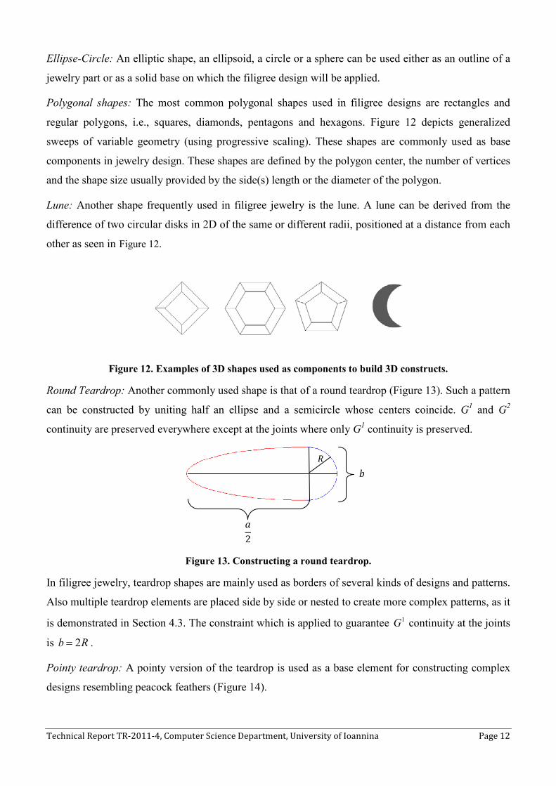
Polygonal shapes: The most common polygonal shapes used in filigree designs are rectangles and
regular polygons, i.e., squares, diamonds, pentagons and hexagons. Figure 12 depicts generalized
sweeps of variable geometry (using progressive scaling). These shapes are commonly used as base
components in jewelry design. These shapes are defined by the polygon center, the number of vertices
and the shape size usually provided by the side(s) length or the diameter of the polygon.
Lune: Another shape frequently used in filigree jewelry is the lune. A lune can be derived from the
difference of two circular disks in 2D of the same or different radii, positioned at a distance from each
other as seen in Figure 12.
Figure 12. Examples of 3D shapes used as components to build 3D constructs.
Round Teardrop: Another commonly used shape is that of a round teardrop (Figure 13). Such a pattern
can be constructed by uniting half an ellipse and a semicircle whose centers coincide. G1 and G
2
continuity are preserved everywhere except at the joints where only G1 continuity is preserved.
Figure 13. Constructing a round teardrop.
In filigree jewelry, teardrop shapes are mainly used as borders of several kinds of designs and patterns.
Also multiple teardrop elements are placed side by side or nested to create more complex patterns, as it
is demonstrated in Section 4.3. The constraint which is applied to guarantee 1G continuity at the joints
is 2b R= .
Pointy teardrop: A pointy version of the teardrop is used as a base element for constructing complex
designs resembling peacock feathers (Figure 14).
�
2
�

Technical Report TR-2011-4, Computer Science Department, University of Ioannina Page 13
The pointy teardrop is created by connecting a circular arc with two line segments originating from T
and being tangent to the circular arc at the endpoints 1S and 2S , as shown in Figure 14. 1S and 2S are
derived from the distance d of the center of the circular arc from T , the radius and center coordinates
of the circular arc. Note that G1 continuity is preserved everywhere except at the tip of the teardrop. G
2
continuity is preserved everywhere except at the tip and at the endpoints 1S and 2 S . To create a
peacock-like pattern pointy teardrops are scaled and placed adjacently with a common tip point T . The
angles ia formed by the line segments are then equal; however different patterns can be derived by
using different configurations for each peacock “feather”.
Figure 14. Pointy teardrops placed relative to each other so as to form a peacock pattern.
Free form shapes: Aside from the shapes described above, other free-form shapes can be used as
jewelry base components. These shapes may be derived after preprocessing [22] by curve fitting on 2D
or 3D points (see [23]) or by deriving 3D custom surfaces by constrained morphing [24].
Spiral Designs: A commonly used design pattern is the spiral. There are numerous spiral types
depending on the equation used. The polar equation of the Archimedean spiral (without rotation) is
r aθ= , where θ is the polar angle of a point on the spiral, and a is a constant that affects the spacing
between two adjacent spiral turns (see Figure 15a).
(a) (b)
Figure 15. (a) Archimedean spiral with radius r and spacing 2=d πα . (b) Logarithmic spiral with 2a =
and 0.2b = .
The affecting parameters of the shape of the spiral are the number of spiral turns k , the distance d
between two adjacent spiral turns, the radius r of the spiral, the total length s of the spiral curve and
the total length of a spiral with k complete spiral turns. Combinations of the above parameters can be
�
�
��
��
�
�
�
�
� �

Technical Report TR-2011-4, Computer Science Department, University of Ioannina Page 14
used to uniquely define a spiral with k complete spiral turns. Since a wire strand is modeled as a
translational sweep of a circular-disk profile of radius wr along a curve trajectory, the following
constraint is applied on the parameters of the spiral curve: the distance between adjacent spiral turns
should not be smaller than the diameter of the wire-cylinder, i.e., 2 wd a rπ= < .
Another type of spiral design that is often found in filigree jewelry is the logarithmic (or equiangular
/golden) spiral. The logarithmic spiral is described by ( ) cos( ) sin( )T
bt btC t ae t ae t = , where a and
b are positive real numbers and btr ae= . An example of the logarithmic spiral is shown in Figure 15b.
3.4 Complex Design Features
By building on the fundamental properties of the wire strands and the basic shapes and designs that are
frequently used in filigree jewelry we define a library of complex design features that are created by
combining the basic elements presented in Sections 3.1, 3.2 and 3.3. The features included in our
filigree design library are: spiral designs, teardrops, teardrop shapes containing spiral designs, nested
teardrop shapes, flower, leaf and peacock patterns, and free-form shapes built using rational Bezier
curves.
Teardrop shapes containing spiral designs: A teardrop filled with spirals is a common pattern
combination in filigree jewelry. To comply with the limitations imposed by the shape of the teardrop,
the radius of the spiral is constrained to fit inside the teardrop and join the teardrop boundary in two or
more points to ensure manufacturability. Teardrop-spiral combinations include either independent
spirals or pairs of spirals connected with a curve so as 1G continuity is preserved for the entire
construct. Figure 16 presents two examples of teardrops containing spirals and connected spiral pairs.
(a) (b)
Figure 16. (a) Teardrop with four spirals. (b) Teardrop with three pairs of connected spirals.
Each spiral should be positioned with respect to the teardrop and to the rest of the spirals. This is
accomplished by defining consecutive, non-overlapping disks fitted in the teardrop. Every new spiral
is drawn in one of these regions and is initially set to have the same center and a radius equal to the
radius of its containing region. Each circle is tangent to the elliptic portion of the teardrop at exactly
two points that are symmetrical with respect to the X -axis, except from the first circle that coincides
with the teardrop semicircle (see Figure 17). Formally, each time we seek the maximal inscribed circle
of the rest of the available area.

Technical Report TR-2011-4, Computer Science Department, University of Ioannina Page 15
Figure 17. Spiral with four inscribed circles
This process that is summarized by the following principle: start from the center of the ellipse (Figure
18) and seek the next circle ( , )n n nC P R that is tangent to the ellipse at some point ( , )aP x y :
2 2
2 2( ) 1 0 a
x yF P
a b= + − = , α n( F(P )) PaP λ+ ∇ = , and is also tangent to the previous circle ( , )p p pC x R :
n a n n sR P P x x= − = − , where s p px x R= + .
(a) (b) Figure 18. Searching for a new inscribed circle in (a) a teardrop and (b) a pointy teardrop.
A similar technique is used in the case where a spiral pair is placed in a pointy teardrop-shape
primitive. The first circle defined coincides with the teardrop semicircle and the next circle is tangent
to the triangular portion of the pointy teardrop at exactly two points. The corresponding equations for
this case are: 1( ) (1 )aP t tS t S= + − , 1( )( ( ) 0)a nS S P t P− − = , ( ) n a n n sR P t P x x= − = − . Consequently,
the formula that computes the next nx and nR in the algorithm becomes:)( s
n
d r xx
r d
+=
+, n n sR x x= − .
The radius of the spiral is the distance between its center and its last point, meaning that the rest of the
spiral points lie in a distance from its center that is less than the radius. As a result the spiral can only
touch one point on the teardrop (i.e., being tangent to the ellipse or the semicircle of the teardrop)
which is insufficient since at least two adjacency points are needed for reasons of manufacturability.
We inscribe a spiral inside a circle of radius cR by extending the spiral angle θ until the spiral touches
the circle, i.e., 2cRk
aθ π γ= = + , where k is the largest integer such that 2 cR
ka
π ≤ . The position of
each spiral endpoint is important to our construction method and therefore a rotation of the spiral is
��
��(�� + ��, 0) −�
��(�� , 0)
��
��
��
��(�� + ��, 0)
��( )
��(�� , 0)
��
��(�, !)

Technical Report TR-2011-4, Computer Science Department, University of Ioannina Page 16
performed by the angle needed for the end point to be drawn at angle ϕ with the y-axis as shown in
Figure 19. The right spiral of the pair is rotated by angle ( )2
πγ ϕ− +
around its center and the left
spiral by angle 3
( )2
πγ ϕ− + around its center (Figure 19). The choice of ϕ affects the aesthetic result
of the connection and is a design parameter.
(a) (b) (c)
Figure 19. (a) An inscribed spiral at its initial position ( 2cR
a
θ κπ γ= = + ), (b) rotated by angle ( )2
πγ ϕ− + to
derive the right part of a spiral pair, and (c) rotated by 3
( )2
πγ ϕ− + to derive the left part of a spiral pair
The first common tangency point between the spiral and the teardrop is either of the two circle/ellipse
tangency points (top or bottom). This is enforced by translating the spiral along the vector from the
center of the spiral towards the circle-ellipse tangency point. The translation is carried out so that the
closest point of the spiral coincides with the circle-teardrop tangency point. From the properties of the
spiral we derive that this will be a tangency point among the spiral, the circle and the teardrop ellipse.
The second adjacency point is created by smoothly connecting the end-point of the spiral with the
other adjacency point using a rational quadratic Bezier curve in an attempt to acquire a curve that
approximates a spiral extension and at the same time is tangent to the circle/teardrop touch point. The
first control point of the Bezier is the end-point of the spiral while the last is the other circle/ellipse
touch point (Figure 20).
To further enhance the approximation quality, 1w is adjusted to obtain a curve segment with curvature
value at control point 0P equal to the curvature value of the spiral at the end-point (note that we use the
standard form of the rational quadratic Bezier curve by setting 0 1 1w w= = ). Note that the curvature of
"
"

Technical Report TR-2011-4, Computer Science Department, University of Ioannina Page 17
a parametric curve [ ]( ) ( ) ( )T
C t x t y t= with parameter t (for an arbitrary non arc length
parameterization) is given by:
3
2 2 2
'( ) ''( ) ''( ) '( ) ( )
( '( ) '( ) )
i
x t y t x t y tk t
x t y t
−=
+
(Eq. 3)
Weight 1w can also be used to yield better aesthetic results. Alternatively, we can also use a cubic
Bezier curve for more degrees of freedom. Figure 20 illustrates how such an extension occurs along
with the corresponding control polygon of the rational Bezier curve.
In the case of single spiral construction, each spiral is constructed independently. However, for spiral
pairs a connector curve segment between the spirals must be established. We use the corresponding
arcs of inscribing circle for connecting the two spirals. This approach maintains G1
continuity and
provides nice aesthetic results for most configurations. Figure 20 shows a pair of non-connected spirals
and the two connecting circular arcs.
(a) (b)
Figure 20. (a) A non-connected pair of spirals and (b) a connected pair of spirals.
Nested Teardrops: Another complex pattern often observed in filigree jewelry is the nested teardrop
(Figure. 21a). This pattern is created by defining n concentric circular arcs of radius ir , such that
1 2 nr r r> >…> and n rational cubic Bezier curves with start and end points coinciding with the start
and end points of the respective circular arcs. The ( 1)n th+ − curve is defined to be a circle.
(a) (b)
Figure. 21 The nested teardrop pattern.
This pattern is frequently embedded in a pointy teardrop shape primitive (Figure. 21). For this to be
feasible, each nested teardrop is created in such a way that all the circular arcs have the same angular
extension, as determined by the distance of the tip of the pointy teardrop, the radius of each circular arc
��
�� �� �� �#
�$
� �$
�
��
�� ��
�� ��
��

Technical Report TR-2011-4, Computer Science Department, University of Ioannina Page 18
and the coordinates of the center of the circular arcs. Cubic rational Bezier curves are used to connect
the end points of the circular arcs with points on the line connecting the tip of the pointy teardrop with
the center C. The inner control points of each cubic Bezier curve are located on the tangents of the
curve end points. We use rational curves and symmetrically modify the weights of the inner control
curves to control the “sharpness” and placement of the tip of the curve. We enforce tangency
constraints at the curve ends to ensure that G1 continuity is preserved at the points where the arcs
connect with the Bezier curves. We may build only the outermost nested G1 pattern and then scale it
appropriately to produce the innermost patterns.
Affecting parameters for the shape of this feature are: the wire strand style (simple, braided,
intersecting pairs etc.) and thickness, the number of nested teardrops n, the center ( , , )C x y z of the n
concentric arcs and the distance d0 between the circle ( )1, nC r + and the tip of largest rational Bezier
curve, (for example in Figure. 21 the tip is 1P ), which affects the inner gap and is aesthetically
important.
To ensure the robustness and accuracy of the pattern, we impose constraints on some of the parameters
of the design. Given a constant thickness t of the wire(s) strand(s) used, the number of nested teardrop
strands that fit in the pattern is constrained by the distance (see Figure. 21). The maximum number of
teardrops n of wire strand thickness t that can be nested is 0 / n d t= .
Other design constraints are:
• The nested teardrop points iP are evenly spaced along 0d : 1 1 2( , ) ( , ),i i i id P P d P P+ + +=
1, , 2i n= −… .
• The nested teardrop arc end points ir are also evenly spaced along 1d : 1 i i sr r v+ = + , 1 , , 1i n= … − .
Given a specific teardrop size and number of nested teardrops, the total thickness of the wire strands t
that can be supported and used in the design can be respectively computed.
Flower Design: Flower designs are commonly used in filigree jewelry. Flower designs in general are
created by combining arch-shaped wires and solid spherical beads that represent the flower petals and
center respectively, thus creating a daisy-like pattern.
Figure 22 presents a 2D sketch of such a flower design. We consider concentric circles 1 1) ( ,C M R that
contain the flower design, and 3 2( , )C M R corresponding to the center of the flower. Given the number
of flower petals n to be used in the flower design, circles 1C and 3 C are divided into n equal
segments, whose borders are defined by lines ( 1, , ).iL i n= … The flower petal corresponding to each
segment is represented by a curve iF ( 1,...,i n= ) that interpolates points ,ijP where 1,...,i n= and
1,..., ,j k= with k referring to the number of points used for interpolation. The start and end points

Technical Report TR-2011-4, Computer Science Department, University of Ioannina Page 19
used for interpolation, i.e., 11P and 15P , are located on curve 3C and are common for adjacent flower
petals, whereas the point corresponding to the tip of each petal, for example 13P , represents the
position where 1C is tangent to the petal.
To ensure model robustness and efficiency, we require that adjacent petals not only have common start
and end points, but also have overlapping/intersecting segments. This is accomplished by considering
a circular guide curve 2 2( , )C M R where 2 3 R R s= + and s corresponding essentially to the length of
the overlapping petal curve segment. The points where lines ,iL that divide the circles into segments,
intersect with circle 2C are used are data input for the interpolating petal curve.
(a) (b)
Figure 22. (a) A 2D sketch of a flower design, (b) variations of the flower pattern
Affecting parameters for the flower design: the flower center bead size, which is defined by the radius
of the sphere constructed in the middle of the flower, the flower petal length, which is defined as the
length 1 3m R R= − , and the number of flower petals n.
Suppose the flower design is to be constructed so that it is not flat on a surface, but at an angle. The
end user specifies an angle α at which the petals are to be located and the circular pattern described
above is mapped onto a conic surface so as to achieve the desired result. The final result is depicted in
Figure 23.
To create the final 3D flower pattern, wire strands are created and transformed based on the profile
curves of the petals. The sphere corresponding to the center of the flower is translated along the
perpendicular axis to obtain a more aesthetically pleasing effect (Figure 23).
%&
��
��
�� '
()
*�
*�
*#
*$
*+
*&
,))
,)-
,).
,)/
,)0
L5
%�
%�
%# %�
%+

Technical Report TR-2011-4, Computer Science Department, University of Ioannina
(a)
Figure 23. (a) The final flower design,
center for a better fit with the petals,
Leaf Patterns: Another common pattern used in filigr
combining curves forming the shape border of the leaf
different approaches to creating leaf patterns
placement of the spirals in the leaf shapes is carried out by exploiting an interesting characteristic of
the golden spiral. Golden spirals are logarithmic spirals
ratio ϕ (Figure 25). Τhe golden rectangle of the spiral is used to implement the placement schemes for
the spirals in the leaves. Placement is performed
(a) Figure 24. (a) A pattern simulating a lanceolate shaped leaf
In the first placement scheme, lanceolate
long and wide in the middle. The shape of the leaf is formed using two symmetric parabolas. These
parabolas are expressed by the equation:
A line segment coinciding with the mirroring axis for the two parabolas is used to represent the spine
of the leaf. The starting points of the decorative golden spirals used are located on this line. Spirals are
placed so that each one intersects the leaf border at one point.
, Computer Science Department, University of Ioannina
(b) (c)
he final flower design, (b) initial flower pattern after construction,
center for a better fit with the petals, (d) alternative design with rounded petals.
Another common pattern used in filigree jewelry is the leaf.
forming the shape border of the leaf with golden spirals (Figure
different approaches to creating leaf patterns depending on the spiral placement scheme used. The
ent of the spirals in the leaf shapes is carried out by exploiting an interesting characteristic of
the golden spiral. Golden spirals are logarithmic spirals where the variable b
he golden rectangle of the spiral is used to implement the placement schemes for
Placement is performed from the bottom to the top of the leaf.
(b) ) A pattern simulating a lanceolate shaped leaf. (b) A pattern simulating a cordate shaped
leaf.
In the first placement scheme, lanceolate shaped leaf patterns are constructed. Lanceolate shapes are
long and wide in the middle. The shape of the leaf is formed using two symmetric parabolas. These
equation: ( ) 2 2 .T
C t at at =
with the mirroring axis for the two parabolas is used to represent the spine
of the leaf. The starting points of the decorative golden spirals used are located on this line. Spirals are
placed so that each one intersects the leaf border at one point.
Page 20
(d)
initial flower pattern after construction, (c) translated beaded
ee jewelry is the leaf. Leaves are created by
Figure 24). We present two
depending on the spiral placement scheme used. The
ent of the spirals in the leaf shapes is carried out by exploiting an interesting characteristic of
b is related to the golden
he golden rectangle of the spiral is used to implement the placement schemes for
from the bottom to the top of the leaf.
pattern simulating a cordate shaped
shaped leaf patterns are constructed. Lanceolate shapes are
long and wide in the middle. The shape of the leaf is formed using two symmetric parabolas. These
with the mirroring axis for the two parabolas is used to represent the spine
of the leaf. The starting points of the decorative golden spirals used are located on this line. Spirals are

Technical Report TR-2011-4, Computer Science Department, University of Ioannina Page 21
(a) (b) (c) Figure 25. (a) A golden rectangle and the corresponding golden spiral. (b) Assembling scaled tangent
golden spirals to form a leaf-like pattern. (c) A leaf-like pattern using freeform curves.
Initially, a golden spiral is placed such that its starting point is located on the spine of the leaf and the
golden rectangle is located inside the leaf. Scaling is performed on the spiral so that it intersects the
parabola at one point. The next spiral with its golden rectangle is placed on top of this spiral so they
are adjacent and then this too is scaled until it intersects the parabola at one point. This process is
carried out recursively either for a defined number of spirals or until no other spirals fit inside the leaf.
Since the leaf is symmetric, the created spirals are mirrored into the other half of the leaf.
Cordate shaped leaf patterns (i.e., heart-shaped leaves with the stem in the cleft) are constructed using
the second placement scheme. Suppose that the bottom left corner of this golden rectangle is
positioned at 1(0,0)P and its height is ph . We seek the height of the next golden spiral that is to be
placed adjacently on top such that the two spirals are tangent to each other at point ( , )TT x s (Figure
25b). Based on the properties of the golden rectangle the height of each newly placed golden spiral
depends on the height of the previously placed golden spiral and the golden ratio. This process is
performed recursively for the desired number of spirals. After placement, the border shape of the leaf
is created using interpolation. It is interesting to note that the top right corners of the golden rectangles
are collinear, due to the fact that the golden rectangles are similar (with a constant ratio). The start and
end points that are chosen for the interpolation, control how pointy and how heart-shaped the tip and
end are, respectively.
Our leaf pattern creation scheme can be generalized to apply not only to other types of spiral curves
but also to more general and/or freeform curves (Figure 25c). The constraint that these curves must
follow is that they intersect with their corresponding bounding box at one point on the top and one
point on the bottom of the bounding box and that these intersecting points are not symmetric.
Peacock Pattern: A peacock, fan-like pattern is often constructed by combining adjacent pointy
teardrop shapes. In this work, the peacock design consists of m pointy teardrop which are sequentially
1
"
ℎ�
ℎ�
�
ℎ�(" − 1)
"
ℎ�" − ℎ�
(0,0)

Technical Report TR-2011-4, Computer Science Department, University of Ioannina Page 22
placed within a center angle a of a virtual circle 1C . Given the center angle a , each pointy teardrop
shape is is placed within a contained angle /a mϕ = . To create each pointy teardrop shape, we use
lines il and jl dividing 1C into the corresponding segment as edges for the teardrop and an arc created
from the intersection points of 1C , il and jl (Figure 26). To create teardrops of different lengths we
assume more virtual circles kC of radius kr and use their intersecting points with the respective line
segments.
Figure 26. Examples of peacock-like patterns.
Affecting parameters: the number of teardrop segments m , the center angle a , the pattern reference
point ( , , )P x y z which is the center of the virtual circle 1C and the radius 1r of 1C , which defines the
actual size of the peacock and the teardrop segments. For this pattern to be robust, the following
constraints must hold: Point P is common for all pointy teardrops and 1
m
i
aϕ=
=∑ .
Free-Form Shapes and Designs: Free-form wire shapes were not very popular in traditional filigree
design. Indeed free-form design occurred usually as connectors between other patterns. Modern
filigree jewelry use higher degree curves that can be derived by interactive CAGD tools (see e.g., [25]
and [26]).
3.5 Decorative Elements
The final aesthetic effect of the designed jewelry is given by elements that are used for decorative
purposes. Solid beads of different sizes are frequently used to decorate the jewelry. These beads are
placed on the model and Boolean union is performed on them and their respective model component.
A plane corresponding to the local surface on which the model component lies at the point where the
bead is imported is used to cut the solid bead to create a flat surface. Jewels and stones can be
embedded in/on jewelry piece. Finally, decorative borders are used which are bolder, thicker,
decorative strands of wires, usually in the form of braids or intersecting pairs.
3 ��
�
4
45
�6
7
��
Technical Report TR-2011-4, Computer Science Department, University of Ioannina Page 23
4 Filigree Jewelry Re-engineering and Reconstruction
An overview of our filigree jewelry re-engineering, design and reconstruction tool suite is presented in
Figure 27. A reverse engineering option is provided that allows the user to load a point cloud and
extract information regarding feature regions and border sets that can be used as guides during the
reconstruction process. For experienced users, a straightforward feature-based computer-aided design
option is also available. Feature design and placement in the jewelry model is supported by inter-
feature constraint definition to allow re-design capabilities. This tool suite has been implemented using
the Microsoft Visual C++ programming environment and the ACIS R18 solid modeling library
provided by Spatial [28].
4.1 Jewelry Re-engineering
The issue of re-engineering jewelry, and especially filigree jewelry, presents many difficulties, mainly
due to the small size and fineness of detail. Re-engineering requires that the produced CAD models are
accurate and robust and fully parameterized to support custom design. To this end, one needs to exploit
the features of the original jewelry model and the relationships and constraints that hold among them.
By applying constraints and fitting features to the point cloud we enhance the semantics and achieve
better accuracy and parameterization. It is still difficult to develop fully automated reverse engineering
systems where there is no human intervention. It is more appropriate to design systems where the user
interacts with the system and provides information that can be used to acquire a more accurate and
complete CAD representation of the object. In our approach we aim to achieve some level of
automation without sacrificing real-time response and high accuracy. This approach has been adopted
successfully by general purpose reverse engineering systems [29].
Reverse engineering techniques have been integrated with our parametric feature-based representation
to achieve some level of automation and to provide reconstruction capabilities. In solid modeling and
computer-aided design, reverse engineering aims to analyze a real object and determine its
characteristics and structure mechanisms, with focus on editability and manufacturability. A piece of
filigree jewelry is usually scanned using a 3D laser scanner producing a point cloud. Due to the
generally small size of jewelry and the delicacy and fineness of their decorative details, scanning
techniques can adequately capture only major design features and their relative placement on the
object that is being scanned. Aesthetic detail cannot be captured in a way that is useful for
reconstruction. An example of a 3D point cloud of a filigree brooch, acquired using a handheld
Handyscan EXASCAN laser scanner (accuracy 40µm), is illustrated in Figure 28. It is clear that the
filigree details of the brooch cannot be inferred from the scanned data. However, we use the point

Technical Report TR-2011-4, Computer Science Department, University of Ioannina Page 24
cloud to extract the overall topology that will guide the identification and placement of the primitives
and the overall shape of the jewelry piece.
Figure 27. An overview of our filigree jewelry reconstruction tool suite.
(a) (b) (c)
Figure 28. (a),(b) The point cloud derived by using a 3D laser scanner on the brooch. (c) Feature
component detection and extraction performed on the point cloud.
4.1.1 Data segmentation
There are various methods that can be used for the segmentation of the initial object, such as [30] and
[31]. An thorough survey of 3D mesh segmentation methodologies examining their suitability for
CAD models is presented in [32]. To detect feature regions we have adapted a method developed
earlier in [33] for reverse engineering based on discovering features on the point cloud by detecting
local changes in the morphology of the underlying geometry. We applied this method on meshes,
where vertex adjacency information is provided a priori. By detecting rapid variations of the surface
Inter-feature
Constraint Definition
Final CAD model
Point cloud
Acquisition
Feature Area
Extraction
Symmetry
Detection
A Priori Feature
Data Extraction
Design/Pattern
Selection
Parameter
definition
Component
construction
Placement
Evaluation
Reverse Engineering Phase Feature Design Phase
for each feature
component
Redesign

Technical Report TR-2011-4, Computer Science Department, University of Ioannina Page 25
normal and measuring the concavity intensity we are able to apply a region-growing technique to
extract a number of regions that represent object features (Figure 28).
More specifically, the concavity intensity of a vertex iv of a mesh, denoted by )( iI v , is the distance of
iv from the convex hull of the mesh. This characteristic is used to detect concave features on the mesh.
Then a region growing is used in order to detect sets of vertices that belong to individual features.
Such an example is illustrated in Figure 28c. The feature regions that are detected correspond to the
basic brooch components: four decorative ensembles, the flower centerpiece and a number of
decorative beads.
By segmenting the point cloud into feature regions and boundary sets, we are able to reconstruct the
boundary contours for each area using curve approximation methods, such as [23]. Reconstructed
boundaries are used in conjunction with a symmetry detection technique [24] for adapting and placing
design elements.
From each detected feature the following data are retrieved:
a) the size of the area covered by the feature by computing the corresponding bounding box,
b) the orientation of the bounding box, based on the principal axes,
c) the feature boundary, by reconstructing the boundary contour from the border sets extracted
during mesh segmentation,
d) the morphology of the feature area, by deriving an initial surface representation using
approximation and fitting. Tensor product surfaces are used to approximate curved areas and
data concerning the curvature of the area is derived, to be used later on in the design process
for operations such as feature component bending.
4.1.2 Symmetry Detection
We use the principal axes of the point cloud to “divide” it into components in which we search for
symmetric feature areas. We create a proximity graph that captures local morphology information as
illustrated in Figure 29, for each part of the object. For each edge, we calculate the geodesic distances
between the centroids of the corresponding feature regions. The graphs are then simplified by reducing
the edges that correspond to large geodesic distances to facilitate region matching. In addition, small
regions that are insignificant are merged.
Elimination of large distance edges is performed motivated by the observation that usually meshes do
not exhibit a general structural similarity but rather a local feature one. In simple cases, where meshes
have an almost identical structure, matching of the corresponding graphs is trivial. For more complex
cases, meshes exhibit only local structural feature similarity. Therefore, by eliminating the edges with

Technical Report TR-2011-4, Computer Science Department, University of Ioannina Page 26
large geodesic distances we match only local neighborhoods in the graph. These local neighborhoods
still capture high-level information about the structure of the features, for example detect pattern
similarities between slightly different models. The reduced morphology graphs are used to perform a
3D alignment of the two sides of the model and establish a correspondence between the regions. This
is achieved by first matching the two highest degree nodes in the two graphs and then performing a 3D
alignment of the two components. The remaining regions are paired according to their degree and the
distance between them. Furthermore, we also take into consideration the area covered by each region
by favoring the matching of regions that have similar areas. We have used the following heuristic
similarity measure for matching:
{ , } { , }
{ , } { , }
max max||
mi min||
n
k mk i j m i j
ij i j
l nl i j n i j
a ds c c
a d= − ε ε
ε ε
(Eq. 4)
where ic and jc are the centroids of regions i and j , ia and
ja are the corresponding areas and id
and jd are the degrees of the nodes in the reduced morphology graphs.
For the example shown in Figure 28c, feature detection derives clusters corresponding to spherical
bead elements in the brooch. Using our symmetry detection method, these beads are matched in pairs
and constructed to fit the respective feature areas, therefore automating significantly the process of
constructing and placing the beads on the brooch. Furthermore, the detected decorative ensemble
components provide data that is used for placement of the ensembles during reconstruction, i.e.,
ensemble orientation and exact location in reference to the base component. Additional approximate
measures are acquired from the detected features in reference to component size and bending angles by
exploiting the oriented bounding box of each feature component data point set. By constructing and
placing one of the ensembles and using transformations to modify and place the remaining, we ensure
robustness and fairness in the model. Also, point sets are extracted that correspond to feature region
boundaries from which free form contours are reconstructed to approximate the border, providing
guide contours for aligning and fitting the design component elements. Finally, the base component of
the brooch is an area on which surface approximation can be performed to derive a basic shape to be
used in the feature-based design process.
The user interface for reverse engineering in ReJCAD is displayed in Figure 30. The user imports the
point cloud that she/he wants to process and performs feature detection to produce an initial list of all
the feature regions and borders. The user can process each feature region detected and either merge it
with others or split it into more components. Symmetry detection is carried out to produce a suggested
list of symmetries which the user can either confirm or reject. Symmetries are suggested to the end

Technical Report TR-2011-4, Computer Science Department, University of Ioannina Page 27
user in pairs of features, while an option is always provided to the user to add his own symmetries
between pairs of features.
(a) (b) Figure 29. (a) The original model divided into two components, according to the major and minor
principal axes. (b) The corresponding morphology graphs for each component.
Figure 30. A snapshot of the ReJCAD user interface.
4.2 The reconstruction process
The feature-based design process is carried out for each feature area that is detected and extracted from
the reverse engineering phase or for each feature component that the user plans on creating based on
her/his design concept.
1
2 3 4 5
6 7 0
A
B C D
E F
G O
A B
C
E
D
F G H
I
O
1 2
3
5
6
7 8
9
0
4
7
1 2 3 4 5 6
G
A B C D E F
5
2 9 3 4 6 7
8 1
E
B I C D F G
H A

Technical Report TR-2011-4, Computer Science Department, University of Ioannina Page 28
Initially the user creates a new feature by picking a pattern/design and defining the parameter values
for the corresponding attributes (Figure 31). If re-engineering has been performed prior to the design
process, then the user can choose a feature region from the feature region list as a guide for initial
parameter values and placement. Intra-feature constraints of designs and patterns are enforced during
parameter definition. For example, the peacock-like aesthetic result of the filigree brooch is secured by
defining the size of the base component pointy teardrops relative to each other. Three teardrop sizes
are used: s for the largest, 0.85s for the middle and 0.75s for the smallest. After construction the
feature is uploaded into a feature list that contains all the feature components (every instance of a
feature) that are part of the final jewelry model. A feature component is redesigned by editing its
parameters, reconstructing it and updating the feature list. The user can also create profile curves by
curve approximation on border point sets obtained through reverse engineering. These profile curves
are used either as guides for placement of a feature or for bending other components along these
curves.
After a feature component is constructed and added to the feature list, placement in the jewelry model
is carried out either manually by the user with free interactive placement or guided by the application,
if re-engineering has been previously performed (Figure 32). In re-engineering guided placement, the
user selects a feature region from the feature region list or a profile curve from the profile list by which
the component is initially aligned and scaled.
Figure 31. Feature-based design in ReJCAD.
Then the user has the ability to transform the component by translation, rotation or scaling, as desired.
Bending of a feature component can be performed prior to placement by specifying the bending
parameters, which include the bending axis/axes and the bending angle. Bending can also be
performed along a curve, by mapping the initial feature component on a profile curve and bending
accordingly, to create more freeform shapes. This option is used in cases where a complex wire strand

Technical Report TR-2011-4, Computer Science Department, University of Ioannina Page 29
(e.g. braid) is used as a decorative border along a base. Bending of compound features is executed after
a Boolean union of the separate features has been performed and the bending axes and angles have
been defined.
Feature placement is combined with inter-feature constraint definition. Constraints are derived and
enforced on the reconstructed jewelry representation to achieve model robustness, conformity to
filigree craftsmanship and to support editability. Constraints related to symmetry are derived through
re-engineering, whereas other constraints are set during the design of each component. The inter-
feature constraints that are supported in ReJCAD mainly refer to component size, bending and
placement. Specifically, size constraints are set either as equalities or symbolic relations. This also
holds for bending angles of feature components. Placement constraints refer to coincidence, tangency
and distance characteristics. More specifically we support the following categories of inter-feature
constraints (intra-feature constraints and parameters are explained in Section 3):
• Determining distances, angles and other geometric characteristics such as radius, area and
volume. Certain distances such as parallel distance between two lines, two planes, or a line and
a plane are translated into two or more primitive distance and angle constraints.
• Fixing geometric elements (thus reducing significantly the degrees of freedom). Over-usage of
fixing may yield inconsistently over-constrained configurations.
• Supporting symbolic relations of angles, distances and other geometric characteristics such as
radius, area, and volume. Symmetry is enforced through relations.
• Imposing “on” constraints. Usually these translate to distances except certain cases that
consume more degrees of freedom such as point on point (consumes three degrees of freedom,
one per coordinate).
• Tangency is supported only for a limited repertoire of geometric primitives.
• Finally, inequalities should be used with caution, since they can be enforced only during the
second step of nonlinear optimization. Otherwise, inequalities are checked through the list of
different solutions derived during the first step of the geometric solving (graph-constructive
solving). This process may take time exponential on the number of constraints.
We use a hybrid geometric constraint solving system. First building on the principles of [34], [35],
[36] we detect minimal concurrent non-linear systems and eliminate symbolic relations. Then we
employ interior point optimization to solve each linear system of geometric constraints [40]. Interior
point optimization is a fast local optimization technique that can be combined with overconstraining to
find efficiently unique solutions for the minimal system of geometric constraints. Root multiplicity is

Technical Report TR-2011-4, Computer Science Department, University of Ioannina Page 30
enabled by combining the subsystems to derive a solution for the entire system of geometric
constraints using the algorithms described in [34].
Figure 32. Placement and constraint definition in ReJCAD.
After the end user is done placing and editing the new component, a test can be performed on the
feature to determine if the final placement is satisfactory for a Boolean union to be performed to
integrate the feature in the final model. The actual union can be performed at a later phase, when the
user has finished with the entire model and its re-design. The final model is checked for robustness and
plausible problems that cannot be handled automatically are reported to the user for editing. The robust
model is exported as an STL file that can be submitted directly for reproduction.
5 ReJCAD Evaluation
In this section we provide a case study where we design and create a filigree brooch according to the
one shown in Figure 1. Also we present a usability study that has been performed to evaluate our
application and discuss the robustness and manufacturability of our constructed CAD models.
5.1 A case study
We present an example of designing and creating a filigree brooch similar to the one illustrated in
Figure 1. This piece of jewelry is made up of essentially two levels of components, the base or main
component and the decorative and complementary elements/subcomponents placed on top.

Technical Report TR-2011-4, Computer Science Department, University of Ioannina Page 31
Initially, the base component of the brooch is created. From the reverse engineering process we cannot
obtain sufficient data about the patterns used for this component, however the general shape,
morphology and size of the area are derived. This component is a complex pattern made up of pointy
teardrops placed in a peacock pattern. The peacock design covers an angle of 360° and consists of 14
pointy teardrop segments. Three circle guide curves are defined to create three different sizes of
teardrops (Figure 33). A simple wire strand type is chosen to create the pattern outline. The
origin/center O of the brooch is placed at the center of the peacock.
(a) (b) (c) Figure 33. (a) A wire outlined peacock pattern as a brooch base component. (b) Brooch base component
featuring nested teardrop patterns. (c) The decorated main component
Next, the design to be featured in each segment is chosen. The same design pattern is chosen for each
segment, the nested teardrop design. The user specifies style and thickness of the wire strands and the
number of strands (Figure 33). The base component is decorated with solid beads and a decorative
braided border. The decorative border is placed by sampling points on the outline of the base
component or using the shape boundary reconstructed from re-engineering, performing curve fitting to
derive the profile curve and then bending a straight braided complex wire of appropriate length to
follow this profile curve (Figure 33). In this case study, the border contour on which the decorative
braid (Figure 38) is fitted on is created using a segment of the boundary contour of each pointy
teardrop and connecting these segments with quadratic rational Bezier curves with 1G continuity. A
parameter k is defined which expresses the percentage of the boundary contour of the pointy teardrop
that is used as part of the braid contour. A larger k means that a larger segment of the available pointy
teardrop boundary is used as part of the braid profile contour; therefore the braid covers more of the
surface of the pointy teardrop (see Figure 34b). Quadratic rational Bezier curves are used to connect
adjacent curve segments. By modifying the weight of the middle control point, we adjust the depth of
the braid contour, which aesthetically affects how closely the braid contour follows the base
component (Figure 34).
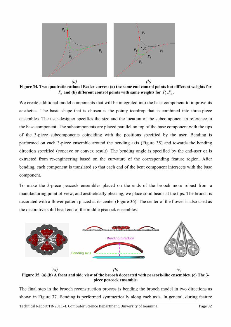
Technical Report TR-2011-4, Computer Science Department, University of Ioannina Page 32
(a) (b) Figure 34. Two quadratic rational Bezier curves: (a) the same end control points but different weights for
2P and (b) different control points with same weights for 2 4, P P .
We create additional model components that will be integrated into the base component to improve its
aesthetics. The basic shape that is chosen is the pointy teardrop that is combined into three-piece
ensembles. The user-designer specifies the size and the location of the subcomponent in reference to
the base component. The subcomponents are placed parallel on top of the base component with the tips
of the 3-piece subcomponents coinciding with the positions specified by the user. Bending is
performed on each 3-piece ensemble around the bending axis (Figure 35) and towards the bending
direction specified (concave or convex result). The bending angle is specified by the end-user or is
extracted from re-engineering based on the curvature of the corresponding feature region. After
bending, each component is translated so that each end of the bent component intersects with the base
component.
To make the 3-piece peacock ensembles placed on the ends of the brooch more robust from a
manufacturing point of view, and aesthetically pleasing, we place solid beads at the tips. The brooch is
decorated with a flower pattern placed at its center (Figure 36). The center of the flower is also used as
the decorative solid bead end of the middle peacock ensembles.
(a) (b) (c) Figure 35. (a),(b) A front and side view of the brooch decorated with peacock-like ensembles. (c) The 3-
piece peacock ensemble.
The final step in the brooch reconstruction process is bending the brooch model in two directions as
shown in Figure 37. Bending is performed symmetrically along each axis. In general, during feature
Bending direction
Bending axis
��
��
��
��
��
�+
�� �$ �#

Technical Report TR-2011-4, Computer Science Department, University of Ioannina
reconstruction and placement, the constraints that are imposed on the model of the filigree brooch can
be summarized as follows:
• All decorative beads is on pointy teardrops are equal in size, meaning same radius
• The peacock ensembles are all equal in size.
• Beads A and B (with centers
are equally distanced from the center
A BC O C O d= =
• The decorative flower is placed at the center of the brooch.
• The peacock ensembles are pair
• Peacock ensembles 1 E and
brooch along bending axis
• Peacock ensembles 3 E and
brooch and the decorative flower.
• The bending angles for all peacock ensembles are equal.
• The bending angle of the middle peacock ensembles
formed by the petals of the flower.
(a)
Figure 36. (a) A 3D model of a filigree brooch prior to bending
(a)
Figure 37. (a) The 3D CAD model of the brooch after bending is performed in two directions,
views of the brooch model after bending in the second direction
Bending
axis 8�
, Computer Science Department, University of Ioannina
reconstruction and placement, the constraints that are imposed on the model of the filigree brooch can
on pointy teardrops are equal in size, meaning same radius
The peacock ensembles are all equal in size.
(with centers AC and BC ) are placed on the horizontal axis
are equally distanced from the center O of the brooch:
The decorative flower is placed at the center of the brooch.
The peacock ensembles are pair-wise symmetric.
and 2E are placed so that their tips coincide with the two ends of the
brooch along bending axis 2 A (Figure 36 and Figure 38).
and 4E are placed so that their tips coincide
brooch and the decorative flower.
The bending angles for all peacock ensembles are equal.
The bending angle of the middle peacock ensembles 3E and 4E must be smaller than the angle
formed by the petals of the flower.
(b)
(c)
) A 3D model of a filigree brooch prior to bending. (b),(c) side views of the
after bending in one direction.
(b)
(c)
) The 3D CAD model of the brooch after bending is performed in two directions,
views of the brooch model after bending in the second direction
Bending
axis 8�
Page 33
reconstruction and placement, the constraints that are imposed on the model of the filigree brooch can
on pointy teardrops are equal in size, meaning same radius ir .
) are placed on the horizontal axis 2 A so that they
(Eq. 5)
are placed so that their tips coincide with the two ends of the
with the center of the
must be smaller than the angle
) side views of the model before and
) The 3D CAD model of the brooch after bending is performed in two directions, (b),(c) side
views of the brooch model after bending in the second direction.

Technical Report TR-2011-4, Computer Science Department, University of Ioannina Page 34
Figure 38. Elements of the brooch on which constraints are enforced.
Custom design and redesign is realized by selecting feature components and modifying their parameter
values. For example, the filigree brooch created above can be modified to achieve the result shown in
Figure 39. The decorative flower center has been removed and the two symmetric peacock ensembles
on the ends of the brooch have been translated to the brooch center, such that their tips touch. Also all
the peacock ensembles are slightly scaled up, to a point where the tips of the top and bottom ensembles
touch the decorative beads of the base component.
Figure 39. A modified version of the filigree brooch.
5.2 Usability Evaluation
We have evaluated our application by conducting a training process. Twelve experienced CAD users
(three engineers with experience on Rhino, four graduate students, two jewelry designers and three
postdocs all not involved in the project research and development) underwent a training session on
how to use the application, created a filigree jewelry model under the guidance of the developers and
then were asked to repeat the procedure by themselves by creating a simplified filigree brooch.
Following this, they were asked to fill in a questionnaire evaluating the application by grading specific
aspects of it on a scale of 0 (weak) to 7 (strong). The questions regarding the application concerned
questions that evaluated two of the major principles of usability: Learnability (Predictability,
Bead B Bead A
Bead
s
Decorative
Braid Border
Peacock
Ensemble
E2
Peacock
Ensemble E1
Peacock
Ensemble E3
Peacock
Ensemble
E4

Technical Report TR-2011-4, Computer Science Department, University of Ioannina Page 35
Familiarity, Generalizability, Consistency) and Robustness (Observability, Recoverability, Task
Conformance) and the three major parameters of usability: Satisfaction, Efficiency and Effectiveness.
The results derived an overall average of: 5.2 out of 7 for efficiency, 5.8 out of 7 for effectiveness and
4.4 out of 7 for subjective satisfaction. The evaluation revealed that users were able to create and
redesign a 3D CAD model of filigree jewelry with satisfactory precision. The general notion among
the users was that the tools provided by the application were sufficient for the task at hand and a
precise model can be constructed for reproduction, however an advanced level of knowledge and
experience in CAD systems is required to be able to use the application effectively and efficiently.
5.3 Robustness and Manufacturability
The CAD model of ReJCAD is exported in STL format and is robust and ready for manufacturing.
Robustness is ensured by performing a number of validity tests on the resulting STL model that results
in removing dangling faces, filling holes and correcting various inconsistencies. Important for the
manufacturability is the concept of feature element overlapping which guarantees stability and direct
casting manufacturability. To this end, besides the per feature wire thickness parameter we provide a
global wire thickness parameter that globally alters wire diameter by 10%± in all features. When
decreasing this parameter the object becomes sharper and when increasing this parameter the object
becomes more coherent. Subsequently, a number of manufacturing methods can be used to produce
jewelry or ornamental pieces.
For reconstructing jewelry pieces of high quality from a robust STL, direct investment casting of
precious metals is the process that yields fine jewelry pieces: First we use rapid prototyping with high
precision machines (with accuracy in the area of 10µm to 70µm voxels) to produce a high quality resin
(or other material) prototype by using 3D printing usually by high resolution photopolymerism
technology per layer. Then an investment is created (usually made of gypsum) from the resin that is
subsequently used for precious metal casting. Note that the resin is such that is vanished completely
without leaving residue and without interacting with the investment usually at moderate burn out
temperatures.
For an overview of such technologies the reader is referred to [37]. Several state of the art machines
supporting these production processes can be found in [38, 39].
For creating more inexpensive faux bijous pieces, current techniques use ceramic or other highly
resistant synthetic material for 3D printing and then a nickel, chrome of copper based mixture of metal
coating is applied. The result is solid and wearable and it may become colorful by using color agents in
the coating material or subsequent silver or gold plating to improve appearance and wearability. Metal
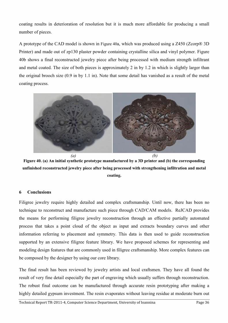
Technical Report TR-2011-4, Computer Science Department, University of Ioannina
coating results in deterioration of resolution but it is much more affordable for producing a small
number of pieces.
A prototype of the CAD model is shown in
Printer) and made out of zp130 plaster powder containing crystalline silica and
40b shows a final reconstructed jewelry piece after
and metal coated. The size of both pieces is approximately 2 in by 1.2 in which is slightly larger than
the original brooch size (0.9 in by 1.1 in).
coating process.
(a) Figure 40. (a) An initial synthetic prototype manufactured by a 3D printer and (
unfinished reconstructed jewelry piece
6 Conclusions
Filigree jewelry require highly detailed and comp
technique to reconstruct and manufacture such piece through CAD/CAM models. ReJCAD provides
the means for performing filigree jewelry reconstruction through an effective
process that takes a point cloud of the object as input and extracts boundary curves and other
information referring to placement and symmetry. This data is then used to guide reconstruction
supported by an extensive filigree
modeling design features that are commonly used in filigree craftsmanship.
be composed by the designer by using our core library.
The final result has been reviewed by jewelry artists and local craftsmen. They have
result of very fine detail especially the part of engraving which usually suffers through reconstruction.
The robust final outcome can be manufactured through accurate resin prototyping after making a
highly detailed gypsum investment. The r
, Computer Science Department, University of Ioannina
coating results in deterioration of resolution but it is much more affordable for producing a small
el is shown in Figure 40a, which was produced using a Z450 (Zcorp® 3D
Printer) and made out of zp130 plaster powder containing crystalline silica and
shows a final reconstructed jewelry piece after being processed with medium stren
of both pieces is approximately 2 in by 1.2 in which is slightly larger than
the original brooch size (0.9 in by 1.1 in). Note that some detail has vanished as a result of the metal
(b) initial synthetic prototype manufactured by a 3D printer and (
unfinished reconstructed jewelry piece after being processed with strengthening infiltration
coating.
Filigree jewelry require highly detailed and complex craftsmanship. Until now, there has been no
technique to reconstruct and manufacture such piece through CAD/CAM models. ReJCAD provides
filigree jewelry reconstruction through an effective
s a point cloud of the object as input and extracts boundary curves and other
information referring to placement and symmetry. This data is then used to guide reconstruction
filigree feature library. We have proposed schemes
modeling design features that are commonly used in filigree craftsmanship. More complex features can
be composed by the designer by using our core library.
The final result has been reviewed by jewelry artists and local craftsmen. They have
result of very fine detail especially the part of engraving which usually suffers through reconstruction.
The robust final outcome can be manufactured through accurate resin prototyping after making a
highly detailed gypsum investment. The resin evaporates without leaving residue at moderate burn out
Page 36
coating results in deterioration of resolution but it is much more affordable for producing a small
which was produced using a Z450 (Zcorp® 3D
Printer) and made out of zp130 plaster powder containing crystalline silica and vinyl polymer. Figure
with medium strength infiltrant
of both pieces is approximately 2 in by 1.2 in which is slightly larger than
Note that some detail has vanished as a result of the metal
initial synthetic prototype manufactured by a 3D printer and (b) the corresponding
strengthening infiltration and metal
lex craftsmanship. Until now, there has been no
technique to reconstruct and manufacture such piece through CAD/CAM models. ReJCAD provides
filigree jewelry reconstruction through an effective partially automated
s a point cloud of the object as input and extracts boundary curves and other
information referring to placement and symmetry. This data is then used to guide reconstruction
We have proposed schemes for representing and
More complex features can
The final result has been reviewed by jewelry artists and local craftsmen. They have all found the
result of very fine detail especially the part of engraving which usually suffers through reconstruction.
The robust final outcome can be manufactured through accurate resin prototyping after making a
esin evaporates without leaving residue at moderate burn out

Technical Report TR-2011-4, Computer Science Department, University of Ioannina Page 37
temperatures. Some experimentation should be performed based on the complexity of the investment
and the metal mixture used for achieving best results for castings using precious metals. A more
affordable solution for manufacturing is to use ceramic or highly resistant synthetic material 3D
printing followed by metal coating.
The feature library can be easily imported and used by other jewelry CAD software such as Rhino or
Matrix by exporting the models through ReJCAD to SAT, 3DM or other appropriate file format. The
same applies for the overall CAD model which can be imported to any jewelry CAD system for adding
precious stones or performing other artistic alterations and corrections in the expense of losing part of
the constraint-based editing capabilities.
7 Acknowledgments
This work was partially supported by Eureka Project #3506, REJCAD under a subcontract for the
Hellenic Center of Gold Silversmiths Trade.
8 References
1. Malagoli MG. CAD/CAM Technology – Transforming the Goldsmith’s Workshop. Gold
Technology, 2002; 34:31-35.
2. Molinari LC, Megazzini MC. The role of CAD/CAM in the modern jewellery business. Gold
Technology, 1998; 23:3-7.
3. Hoffmann C.M., Joan-Arinyo R. On User-defined Features. Computer Aided Design, 1998;
30(5):321-332.
4. Bronsvoort W., Bidarra R., van der Meiden H.,Tutenel T. The Increasing Role of Semantics in
Object Modeling. Computer Aided Design and Applications, 2010; 7(3):431-440.
5. Bohm W. Design Opportunities through production technology. Gold Technology, 1998; 23:8-
11.
6. Stamati V., Fudos I. A parametric feature-based CAD system for reproducing traditional
pierced jewellery. Computer Aided Design, 2005; 37(4):431.
7. Stamati V., Fudos I., Building editable Brep models from unorganized point clouds, 2010,
University of Ioannina, C.S. Dept., TR.2010-04
8. Andrews C., Ancient Egyptian Jewellery. 1990: British Museum Publications
9. Untracht O., Jewelry of India. 1997: Thames and Hudson.
10. Sequin C. CAD tools for aesthetic engineering. Computer-Aided Design, 2005; 37:737-750.
11. Sequin C. Computer-Aided Design and Realization of Geometrical Sculptures. Computer-
Aided Designs and Applications, 2007; 4(5):671-681.
12. Furuta Y., Mitani J., Igarashi T.,Fukui Y. Kinetic art design system comprising rigid body
simulation. Computer Aided Design and Applications, 2010; 7(4):533-546.
13. Liu Y., Zhang D.,Yuen M. A survey on CAD methods in 3D garment design. Computers in
Industry, 2010; 61:576-593.
14. Jewellery CAD/CAM Limited. JewelCAD. Available from: http://www.jcadcam.com.
15. Robert McNeel & Associates. Rhinoceros, NURBS modleing for Windows. Available from:
http://www.rhino3d.com/jewelry.htm.
16. Delcam. ArtCAM JewelSmith. Available from: http://www.artcamjewelsmith.com/.

Technical Report TR-2011-4, Computer Science Department, University of Ioannina Page 38
17. Gemvision. Matrix 3D Jewelry Design Software. Available from:
http://www.gemvision.com/html/products/matrix/matrix.html.
18. 3Design. 3Design CAD. Available from: http://www.3design.com/.
19. Gulati V., Singh H.,Tandon P. A parametric voxel based unified modeler for creating carved
jewerly. Computer Aided Design and Applications, 2008; 5(6):811-821.
20. Gulati V., Tandon P.,Singh H. A Jewelry Modeler for the Fret-worked Bangles. International
Journal of Computer Applications, 2010; 2(2):76-80.
21. Kai C.C.,Gay R. CAD/CAM/CAE for ring design and manufacture. Computer-Aided
Engineering 1991; February:13-24.
22. Liu Y., Paul J., Yong J., Yu P., Zhang H., Sun J.,Ramani K. Automatic least-squares projection
of points onto point clouds with applications in reverse engineering Computer-Aided Design
2006; 38(12):1251-1263.
23. Stamati V., Fudos I. On Reconstructing 3D Feature Boundaries. Computer Aided Design and
Applications, 2008; 5(1-4):316-324.
24. Athanasiadis T., Fudos I., Nikou C.,Stamati V. Feature-based 3D morphing based on
geometrically constrained sphere mapping optimization. in SAC 2010. 2010.
25. Llamas I., Kim B., Gargus J., Rossignac J.,Shaw C. Twister: a space-warp operator for the two-
handed editing of 3D shapes. in ACM SIGGRAPH 2003. 2003: ACM.
26. Rossignac J.,Schaefer S. JSplines. Journal of Computer-Aided Design, 2008; 40(10-11):1024-
1032.
27. Bates L., Wyvill B.,Yao C. The visualization of knots and braids. The Journal of Visualization
and Computer Animation, 1992; 3(2):91-104.
28. Spatial. ACIS 3D Modeling Available from: http://www.spatial.com.
29. Fisher R.B. Applying knowledge to reverse engineering problems. Computer-Aided Design,
2004; 36:501-510.
30. Varady T., Facello M.,Terek Z. Automatic extraction of surface structures in digital shape
reconstruction. Computer Aided Design, 2007; 39:379-388.
31. Stamati V., Reconstructing feature-based CAD models based on point cloud morphology, in
Dept. of Computer Science. 2008, University of Ioannina: Ioannina.
32. Agathos A., Pratikakis I., Perantonis S., Sapidis N.,Azariadis P. 3D Mesh Segmentation
Methodologies for CAD applications. Computer-Aided Design and Applications, 2007;
4(6):827-842.
33. Stamati V., Fudos I. A Feature-Based Approach to Re-engineering Objects of Freeform Design
by Exploiting Point Cloud Morphology. in SPM 2007: ACM Symposium on Solid and Physical
Modeling. 2007. Beijing, China.
34. Fudos I., Hoffmann C.M. A graph-constructive approach to solving systems of geometric
constraints. ACM Transactions on Graph(EnvisionTec)ics, 1997; 16(2):179-216.
35. Hoffmann C.M., Joan-Arinyo R. Symbolic Constraints in Constructive Geometric Constraint
Solving. J. Symbolic Computation 1997; 23:287-299.
36. de Regt R., van der Meiden H., Bronsvoort W. A Workbench for Geometric Constraint
Solving. Computer Aided Design and Applications, 2008; 5(1-4):471-482.
37. Wannarumon S., Bohez E. L. J. Rapid Prototyping and Tooling Technology in Jewelry CAD.
Computer Aided Design and Applications, 2004; 1(1-4):569-576.
38. LB Jewelry Design,Inc. Jewelry Design. Available from: http://www.lbjewelrydesign.com/.
39. EnvisionTec. (n.d.). EnvisionTec Jewelry. Retrieved from http://www.envisiontec.de