V-port segment valves - Metsovalveproducts.metso.com/documents/neles/IMOs/en/3R71en.pdf · 10.1 R1L...
24
V-port segment valves Series R1L Titanium Series R21L Titanium Series R2_S High consistency Installation, Maintenance and Operating Instructions 3 R 71 en • 9/2017
Transcript of V-port segment valves - Metsovalveproducts.metso.com/documents/neles/IMOs/en/3R71en.pdf · 10.1 R1L...

V-port segment valvesSeries R1L TitaniumSeries R21L TitaniumSeries R2_S High consistency
Installation, Maintenance andOperating Instructions
3 R 71 en • 9/2017

2 3 R 71 en
READ THESE INSTRUCTIONS FIRST!
These instructions provide information about safe handling and operation of the valve.If you require additional assistance, please contact the manufacturer or manufacturer's representative.Addresses and phone numbers are printed on the back cover.
SAVE THESE INSTRUCTIONS!
Subject to change without notice.All trademarks are property of their respective owners.
Table of Contents1 GENERAL ..............................................................3
1.1 Scope of the manual ...........................................31.2 Valve construction ...............................................31.3 Valve markings ......................................................31.4 Technical specifications .....................................41.5 Valve approvals ..................................................... 41.6 CE marking ..............................................................41.7 Recycling and disposal .......................................41.8 Safety precautions ...............................................5
2 TRANSPORTATION, RECEPTION AND STORAGE ..............................................................5
3 INSTALLATION AND COMMISSIONING ............. 53.1 General .....................................................................53.2 Installing in the pipeline ....................................53.3 Actuator ................................................................... 63.4 Commissioning .....................................................6
4 MAINTENANCE .................................................... 64.1 Maintenance general ..........................................64.2 Replacing the gland packing ...........................74.3 Detaching the actuator ...................................... 74.4 Removing the valve from the pipeline .........74.5 Replacing the seat ................................................74.6 Dismantling the valve .........................................94.7 Inspection of removed parts ......................... 104.8 Assembly .............................................................. 10
5 TESTING THE VALVE ..........................................106 INSTALLING THE ACTUATORS ..........................11
6.1 General .................................................................. 116.2 Installing B1C actuators ................................. 116.3 Installing B1J actuators .................................... 11
7 MALFUNCTIONS ................................................128 TOOLS ................................................................ 129 ORDERING SPARE PARTS ..................................1210 EXPLODED VIEW AND PARTS LISTS .................13
10.1 R1L and R21 Titanium ...................................... 1310.2 R2_S, sizes DN80 - 300/3" - 12" ..................... 1410.3 R2_S, sizes DN350 - 400/14" - 16" ................ 15
11 DIMENSIONS ......................................................1611.1 Series R1 ................................................................ 1611.2 Series R21 ............................................................. 1811.3 Series R2_S........................................................... 20
12 TYPE CODE .........................................................23
3 R 71 en 3
1 GENERAL
1.1 Scope of the manualThis manual provides essential information on R series V-port segment valves. Actuators and other accessories areonly discussed briefly. Refer to the individual manuals forfurther information on their installation, operation andmaintenance..
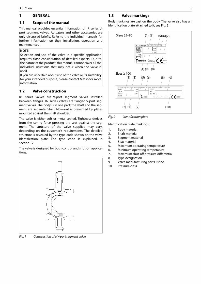
1.2 Valve constructionR1 series valves are V-port segment valves installedbetween flanges. R2 series valves are flanged V-port seg-ment valves. The body is in one part; the shaft and the seg-ment are separate. Shaft blow-out is prevented by platesmounted against the shaft shoulder.
The valve is either soft or metal seated. Tightness derivesfrom the spring force pressing the seat against the seg-ment. The structure of the valve supplied may vary,depending on the customer’s requirements. The detailedstructure is revealed by the type code shown on the valveidentification plate. The type code is explained insection 12.
The valve is designed for both control and shut-off applica-tions.
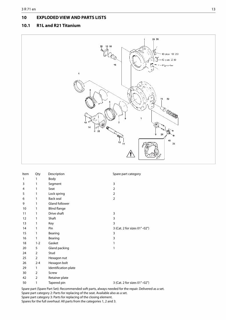
1.3 Valve markingsBody markings are cast on the body. The valve also has anidentification plate attached to it, see Fig. 3.
Identification plate markings:
1. Body material2. Shaft material3. Segment material4. Seat material5. Maximum operating temperature6. Minimum operating temperature7. Maximum shut-off pressure differential8. Type designation9. Valve manufacturing parts list no.10. Pressure class
NOTE:Selection and use of the valve in a specific applicationrequires close consideration of detailed aspects. Due tothe nature of the product, this manual cannot cover all theindividual situations that may occur when the valve isused.If you are uncertain about use of the valve or its suitabilityfor your intended purpose, please contact Metso for moreinformation.
Fig. 1 Construction of a V-port segment valve
Fig. 2 Identification plate
ATTENTION:
TYPE
BODY
No.SEATTRIM
max
psmin
INSTALLATION OR SERVICING.
tt
READ INSTRUCTIONS BEFORE
Made byMetso Flow Control
XXXX
BODYTRIMSHAFTSEAT
TYPE
RATINGNo.
t max.t min.
ps
ATTENTION: READ INSTRUCTIONS BEFORE INSTALLAT ION OR SER V IC ING. CONTACT METSO AUTOMATION FOR COPY.
Made by Me tso Flow Con t ro l XXXX
Sizes 25–80
Sizes ≥ 100
(1) (3) (5) (6)(7)
(4) (9) (8)
(1) (3) (5) (6) (8) (9)
(2) (4) (7) (10)

4 3 R 71 en
1.4 Technical specificationsFace-to-face length:
R1L: special lengthR21: according to ISA S75.04 and
IEC/DIN 534-3-2R2_S: special length
Body rating: see Section 12
Max. pressure differential: see Fig. 4 and 5
Temperature range: see Fig. 3
Flow direction: indicated by an arrow onthe body
Dimensions: see Section 11
Weights: see Section 11
1.5 Valve approvalsThe valve meets the Fire-safe requirements of BS6755/API607 Edition 3.
1.6 CE markingThe valve meets the requirements of the European Direc-tive 97/23/EC relating to pressure equipment, and has beenmarked according to the Directive.
1.7 Recycling and disposalMost valve parts can be recycled if sorted according tomaterial. Most parts have material marking. A material list issupplied with the valve. In addition, separate recycling anddisposal instructions are available from the manufacturer. Avalve can also be returned to the manufacturer for recyclingand disposal against a fee.
Fig. 3 Maximum pressure differentials of R series valves
Fig. 4 Maximum pressure differentials of acid-resistantand carbon-steel standard valves in control and on-off operation
Fig. 5 Maximum pressure differentials of standard tita-nium valves in control and on-off operation

3 R 71 en 5
1.8 Safety precautions
2 TRANSPORTATION, RECEPTION AND STORAGE
Check the valve and the accompanying devices for anydamage that may have occurred during transport.
Store the valve carefully before installation, preferablyindoors in a dry place.
Do not take the valve to the intended location and do notremove the flow port protectors until the valve is installed.
The valve is delivered in the closed position. A valveequipped with a spring-return actuator is delivered in theposition determined by the spring.
3 INSTALLATION AND COMMISSIONING
3.1 GeneralRemove the flow port protectors and check that the valve isclean inside.
3.2 Installing in the pipelineFlush or blow the pipeline carefully before installing thevalve. Foreign particles, such as sand or pieces of weldingelectrode, will damage the segment sealing surface andseats.
The valve has an arrow indicating the flow direction. Installthe valve in the pipeline so that the flow direction of thepipe corresponds to that marked on the valve. The mount-ing position does not place restrictions on operation of thevalve, actuator or positioner. You should, however, avoidinstalling the valve so that the shaft points downwardsbecause impurities travelling in the pipeline may then enterthe body cavity and damage the gland packing. See Fig. 7.
Choose flange gaskets according to the operating condi-tions.
Do not attempt to correct pipeline misalignment by meansof flange bolting.
Stress caused in the valve by pipeline vibration can bereduced by supporting the pipeline properly. Reducedvibration also helps ensure correct functioning of the posi-tioner.
CAUTION:Do not exceed the valve performance limitations!Exceeding the limitations marked on the valve may causedamage and lead to uncontrolled pressure release. Dam-age or personal injury may result.
CAUTION:Do not dismantle the valve or remove it from thepipeline while the valve is pressurized!Dismantling or removing a pressurized valve will result inuncontrolled pressure release. Always isolate the relevantpart of the pipeline, release the pressure from the valveand remove the medium before dismantling the valve.Be aware of the type of medium involved. Protect yourselfand the environment from any harmful or poisonous sub-stances. Make sure that no medium can enter the pipelineduring valve maintenance.Failure to do this may result in damage or personal injury.
CAUTION:Beware of the segment movement!Keep hands, other parts of the body, tools and otherobjects out of the open flow port. Leave no foreignobjects inside the pipeline. When the valve is actuated,the segment functions as a cutting device. The segmentposition may also change when the valve is moved. Closeand detach the actuator pressure supply pipeline for valvemaintenance. Failure to do this may result in damage orpersonal injury.
CAUTION:Protect yourself from noise!The valve may produce noise in the pipeline. The noiselevel depends on the application. It can be measured orcalculated using the Metso Nelprof software. Observe therelevant work environment regulations on noise emission.
CAUTION:Beware of a very cold or hot valve!The valve body may be very cold or very hot during use.Protect yourself against cold injuries or burns.
CAUTION:When handling the valve or the valve package, take itsweight into account!Never lift the valve or valve package by the actuator, posi-tioner, limit switch or their piping.Place the lifting ropes securely around the valve body (seeFig. 7). Damage or personal injury may result from fallingparts.
Fig. 6 Lifting the valve
CAUTION:When handling the valve or the valve package, take itsweight into account!

6 3 R 71 en
Servicing is facilitated if the valve needs no support. If neces-sary, you can support the valve by the body, using regularpipe clamps and supports. Do not fasten supports to theflange bolting or the actuator, see Fig. 8.
3.3 Actuator
The valve closed and open positions are indicated as fol-lows:
by a marking on the actuator, or by a groove at the end of the valve shaft.Both show the position of the segment with respect to theflow port. If there is any uncertainty about the marking,check the position of the segment by the groove at the endof the shaft, see Fig. 9.
If possible, install the valve so that the actuator can be dis-connected without removing the valve from the piping.
The actuator must not touch the pipeline, because pipelinevibration may damage it or interfere with its operation.
In some cases, for instance when a large-size actuator isused or when the pipeline vibrates heavily, supporting theactuator is recommended. Contact Metso’s Automationbusiness for further information.
3.4 CommissioningEnsure that no dirt or foreign objects are left inside thevalve or pipeline. Flush the pipeline carefully. Keep thevalve entirely open during flushing.
Check all joints, pipings and cables.
Check that the actuator, positioner and limit switches arecorrectly adjusted. Refer to their installation, operation andservice manuals.
The gland packing may leak after prolonged storage.Tighten the packing evenly at both nuts until the leakagestops.
4 MAINTENANCE
4.1 Maintenance generalAlthough Metso’s Neles valves are designed to work undersevere conditions, proper preventative maintenance can sig-nificantly help to prevent unplanned downtime and in realterms reduce the total cost of ownership. Metso recom-mends inspecting the valves at least every five (5) years. Theinspection and maintenance interval depends on the actualapplication and process condition. The inspection and main-tenance intervals can be specified together with your localMetso experts. During this periodic inspection the partsdetailed in the Spare Part Set should be replaced. Time instorage should be included in the inspection interval.
Maintenance can be performed as presented below. Formaintenance assistance, please contact your local Metsooffice. The part numbers in the text refer to the explodedview and to the parts list in Section 10, unless otherwisestated.
Fig. 7 Installing the valve into pipeline
Fig. 8 Supporting the valve
NOTE:When installing the actuator, make sure that the valve-actuator combination functions properly. Detailed infor-mation on actuator installation is given in Section 6 or inseparate actuator instructions.
Fig. 9 Closed and open positions
CAUTION:
Observe the safety precautions mentioned in Section1.8 before maintenance!
CAUTION:
When handling the valve or the valve package as awhole, bear in mind the weight of the valve or theentire package!
CAUTION:For safety reasons the retaining plates MUST alwaysbe installed acc. to Section 4.2.
CLOSED OPEN

3 R 71 en 7
4.2 Replacing the gland packing
In gland packings, tightness is ensured by the contactbetween the gland follower and the packing rings. SeeFig. 10.
The gland packing (20) must be replaced if leakage occurseven after the hexagon nuts (25) have been tightened.
Make sure that the valve is not pressurized. Unfasten the nuts (25) and remove the retaining
plates (42) and the gland follower (9). Remove the five old packing rings (20). Clean the packing ring counterbore. Mount the new
packing rings one by one using the gland follower asa tool. Mount the retaining plates with the textUPSIDE on top (see Fig. 10).
Place the nuts on the studs and tighten the glandpackings (see Table 1).
The actuator may be detached to facilitate the work.
4.3 Detaching the actuator
It is generally most convenient to detach the actuator andits auxiliary devices before removing the valve from thepipeline. If the valve package is small or if it is difficult toaccess, it may be more practical to remove the entire pack-age at the same time.
Disconnect the actuator from its power source;detach the air supply pipe and control signal cable-sor pipesfrom their connectors.
Unscrew the bracket screws. Detach the actuator using a suitable extractor. The
tool can be ordered from the manufacturer. Remove the bracket and coupling, if any.
4.4 Removing the valve from the pipeline
Make sure that the pipeline is not pressurized andthat it is empty. Also make sure that no medium isled into the pipeline while the valve is beingremoved or after it has been removed.
Place the hoisting ropes carefully, unscrew the pipeflange bolts and lift the valve from the pipeline usingthe ropes. Note the correct lifting method. See alsoFig. 6.
4.5 Replacing the seat
4.5.1 Detaching the seat The valve must be removed from the pipeline. Turn the segment (3) so that it does not touch the
seat, Fig. 11.
NOTE:When sending goods to the manufacturer for repair, donot disassemble them. Clean the valve carefully and flushthe valve internals. For safety reasons, inform the manu-facturer of the type of medium used in the valve (includematerial safety datasheets (MSDS)).
NOTE:In order to ensure safe and effective operation, always useoriginal spare parts to make sure that the valve functionsas intended.
NOTE:For safety reasons, replace pressure retaining bolting if thethreads are damaged, have been heated, stretched or cor-roded.
CAUTION:Do not dismantle the valve or remove it from the pipe-line while the valve is pressurized!
Fig. 10 Installing the retainer plates
Table 1 Torques for the gland packing nuts
Thread Torque, Nm5/16 UNC 103/8 UNC 201/2 UNC 50
CAUTION:When handling the valve or the valve package, take itsweight into account!
NOTE:Before dismantling, carefully observe the position of thevalve in relation to the actuator and positioner/limitswitch so as to make sure that the package can be prop-erly re-assembled.
CAUTION:Do not dismantle the valve or remove it from the pipe-line while the valve is pressurized!
Fig. 11 Turning the ball segment

8 3 R 71 en
In DN 25-40 valves (excluding the low-Cv versions),unfasten the flange (10) and push the segment intothe back position (Fig. 12).
DN 25 / 1" valves can be dismantled, as described in4.6, to make the replacement of the seat easier. Dis-mantling is always necessary when a DN 25 / 1" valvehas a low-Cv segment. If a DN 25 / 1" valve with alow-Cv segment has an extra bushing (ø 33 mm /1.3") in the downstream bore, send the valve to themanufacturer for repair.
Tap the seat (4) with a soft spindle all around the cir-cumference from the upstream side to make it fallinto the body, Fig. 13.
Turn the valve and lift the seat from the bodythrough the downstream flow port, Fig. 17.
Clean and check the removed parts.
4.5.2 Installing the seatThe back seal (6) of the segment seat (4) is normally a lipseal. The seat is easier to install if the back seal is precom-pressed. An O-ring seal does not need precompression.
Clean the flow port that houses the seat. Removeany burrs. Round off the edges using a fine abrasivepaper and clean the flow port carefully, see Fig. 15.
Place the back seal (6) onto the seat (4). Lubricate the flow port, seat (4) and back seal (6) and the
lock spring (5) with a volatile lubricant, e.g. Hyprez.Make sure that the lubricants are compatible withthe medium.
Only for a lip seal: Push the seal carefully into theflow port for about 15 minutes, Fig. 16. The followingwork phases must be completed before the precom-pression is lost.
Place the lock spring (5) on the seat. When the valve is opened, the ends of the spring
must be by the V-shaped opening, see Fig. 17.
Fig. 12 Removing the blind flange
Fig. 13 Knocking off the seat
Fig. 14 Lifting the seat
Fig. 15 Rounding the sharp edges
Fig. 16 Precompression of the lip seal
Fig. 17 Mounting the seat
sharp edgesmust berounded off
sharp edgesmust berounded off

3 R 71 en 9
Place the seat package into the body as shown inFigs. 18 and 19.
Check that the spring angles extend to the controlface.
Place a screwdriver on each visible spring angle oneafter the other and knock the spring into the groove,see Fig. 20.
Turn the segment 180° clockwise and knock the restof the spring angles into the groove, Fig. 21. A spe-cial tool available from the manufacturer may alsobe used for the work phases in Figs. 20 and 21.
Use a plastic spindle to ensure that the seat is cor-rectly placed and can move freely, Fig. 25.
4.6 Dismantling the valve Turn the valve into the closed position. Remove the pin lockings either by grinding or using
a spindle. Detach the pins (14 and 15) by drilling,Fig. 23. Be careful not to damage the original bores.Note! The pins and the drive shaft have beensecured by welding in the titanium version and inthe acid-resistant high-consistency version S.
Fig. 18 Slipping the seat into the body
Fig. 19 Pushing the the spring angles against the controlface
Fig. 20 Knocking the spring into the groove
Fig. 21 Knocking the spring after turning the seat around
Fig. 22 Securing with a plastic spindle
Fig. 23 Drilling the pin, R1L and R2_S
Conical pin
part no. 50
DN 25...300
A - A
AA
Cylindrical pin
part no. 14
DN 25...40
Cylindrical pin
part no. 14
DN 50...400
DN DRILL ø (mm) L (mm)
25, 40 2,0 18
50 3,5 25
80, 100 4,2 33
150 5,0 43
200 7,0 52
250, 300 8,8 60
350, 400 12,0 90
L
Cylindrical pin
part no. 15
DN 350...400
AA L

10 3 R 71 en
Detach the retainer plates (42). Detach the gland packings (20). Remove the shafts (11 and 12), Fig. 24. Lift the segment from the body. Remove the bearings (15 and 16) and clean the bear-
ing spaces. Remove the seat by pushing it evenly inside the
body.
4.7 Inspection of removed parts Clean the removed parts. See if the shafts (11, 12) and bearings (15, 16) are
damaged. Check if the sealing surfaces of the segment and the
seat (4) are damaged. If necessary, replace the parts with new.
4.8 Assembly Put the bearings (15, 16) in their places. Mount the seat as explained in Section 4.5.2. Mount the segment in the body in the closed posi-
tion. Press the segment to fit the shaft (12).
Install the drive shaft (11). Note the location of thepin hole and the keyway. See Fig. 25.
Please note the depth of the hole (L) for the conicalpin (Fig. 23). Put the pins (14, 50) in their places andlock them (Fig. 26). Both pins are locked with TIGwelding in the high-consistency acid-resistant ver-sion and in the standard and high-consistency tita-nium versions. Moreover, the drive shaft is welded tothe segment in the high-consistency versions. Con-tact the manufacturer for more information.
Install the blind flange (10) with gaskets (19), tightenthe bolts (26), see Table 2.
Install the gland packing (20) and retainer platesaccording to Section 4.2.
5 TESTING THE VALVE
We recommend that the valve body be pressure testedafter the valve has been assembled.
The pressure test should be carried out in accordance withan applicable standard using the pressure rating requiredby the pressure class or flange bore of the valve. The valvemust be in the open position during the test.
If you also want to test the tightness of the closure member,contact the manufacturer.
Fig. 24 Removing the shafts
Fig. 25 Segment and shaft position
SHAFT WITH KEYWAY marker line
segment ball surface
Fig. 26 Locking a pin
Table 2 Screw torques (for lubricated screws)
Screw M6UNC 1/4
M8UNC 5/16
M10UNC 3/8
M12UNC 1/2
Torque, Nm 8 18 35 65
CAUTION:Pressure testing should be carried out using equip-ment conforming to the correct pressure class!

3 R 71 en 11
6 INSTALLING THE ACTUATORS
6.1 GeneralDifferent Metso actuators can be mounted using suitablebrackets and couplings. The valve can be operated, forexample, by actuators of the B1 or Quadra-Powr series.
6.2 Installing B1C actuators
Drive the actuator piston to the extreme outwardposition and turn the valve into the closed position,see Fig. 9.
Clean the shaft bore and file off any burrs. Lubricatethe shaft bore.
If a coupling is needed between the actuator shaftbore and the valve shaft, lubricate the coupling andinstall it in the actuator.
Fasten the bracket loosely to the valve using lubri-cated screws.
Push the actuator carefully onto the valve shaft.Avoid forcing it, since this may damage the segmentand seat. We recommend mounting the actuator sothat the cylinder is pointing upwards.
Align the actuator as accurately as possible using thevalve as a guide. Lubricate the mounting screws.Install the washers and tighten all screws, seeTable 4.
Adjust the segment open and closed positions (lim-its to piston movement) by means of the actuatorstop screws, see Fig. 24. The correct opening angle is90°, for the R2_S valve 70°. The accurate position canbe seen in the flow port. Check that the yellow arrowindicates the position of the segment.Keep your fingers out of the flow port!
There is no need to adjust the stop screw if the actuator isre-installed in the same valve. Drive the actuator piston tothe housing end (open position).Turn the actuator by handuntil the valve is in the open position (unless it is alreadyopen). Fasten the actuator in this position. The actuatormay be installed in another position with respect to thevalve by selecting another keyway in the actuator, seeFig. 28.
Check the tightness of the stop screw at the end ofthe cylinder during cylinder operation. The threadsmust be sealed using an appropriate non-hardeningsealant, e.g. Loctite 225.
Check that the actuator is functioning correctly.Check the segment flow bore position and the actu-ator movement relative to the valve (clockwise:close, counterclockwise: open) after installing theactuator. The valve should be closed when the pis-ton is in the extreme outward position.
Check that the yellow arrow indicates the position ofthe segment. If necessary, change the position of thearrow.
6.3 Installing B1J actuatorsSpring-return actuators are used in applications wherevalve opening or closing movement is needed in case theair supply is interrupted. The B1J type is used for spring-to-close operation; the spring pushes the piston towards thecylinder end, the extreme outward position. In turn, theB1JA type is used for spring-to-open operation; the springis between the piston and the cylinder end and pushes thepiston towards the housing.
Spring-return actuators are installed in a manner similar toB1C series actuators, taking into account the following.
6.3.1 Type B1JInstall the actuator so that the piston is in the extreme out-ward position. The cylinder must not be pressurized and airsupply connections must be open. The valve must be in theclosed position, see Fig. 9.
6.3.2 Type B1JAInstall the actuator so that the piston is in the cylinder-endposition at housing side. The cylinder must not be pressur-ized and the air supply connection must be open. The valvemust be in the open position, see Fig. 9.
The rest of the installation procedure is the same as for B1Cactuators.
CAUTION:Beware of the segment movement!
Fig. 27 Open and closed positions of a B1 actuator
Stop screw for theOPEN position
Stop screw for theCLOSED position
Fig. 28 Changing the actuator position

12 3 R 71 en
7 MALFUNCTIONSTable 3 lists malfunctions that might occur after prolongeduse.
8 TOOLSIn addition to standard tools, the following special toolsmight be needed to facilitate working. The tools can beordered from the manufacturer.
For removal of the actuator- Extractor (ID-code table in actuator's IMO).
For mounting and removal of the seat- Seat mounting tool (table 4).
9 ORDERING SPARE PARTS
When ordering spare parts, always include the followinginformation:
type code, sales order number, serial number(stamped on a valve body)
number of the parts list, part number, name of thepart and quantity required
This information can be found from the identification plateor documents.
Table 3 Possible malfunctions
Symptom Possible fault Recommended actionLeakage through a closed valve
Wrong stop screw adjustment of the actuator Adjust the stop screw for closed positionFaulty zero setting of the positioner Adjust the positionerDamaged seat Replace seatDamaged segment Replace segmentSegment in a wrong position relative to the actuator
Select the correct keyway in the actuator
Irregular valve movements Actuator or positioner malfunction Check the operation of the actuator and positionerProcess medium accumalated on the segment surface
Clean the segment
Segment or seat damaged Replace the segment or seatCrystallizing medium has entered the bearing spaces
Flush the bearing spaces
Gland packing is leaking Gland packing set worn or damaged Replace the gland packing set
Table 4 Seat mounting tool (Valve Series R1, R2)
Product: ID:DN 01 273336DN 015 273337DN 02 273338DN 03 273339DN 04 273340DN 06 273341DN 08 273342DN 10 273343DN 12 273344
NOTE:Always use original spare parts to make sure that the valvefunctions as intended.
3 R 71 en 13
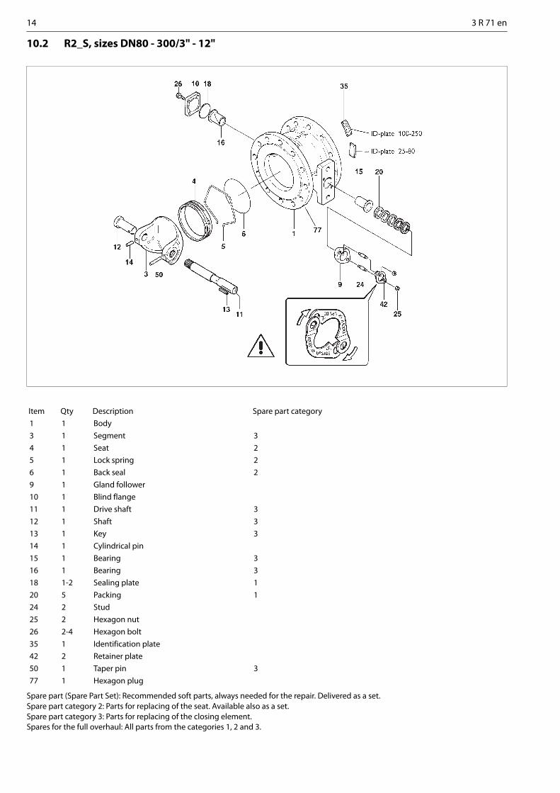
10 EXPLODED VIEW AND PARTS LISTS
10.1 R1L and R21 Titanium
Spare part (Spare Part Set): Recommended soft parts, always needed for the repair. Delivered as a set.Spare part category 2: Parts for replacing of the seat. Available also as a set.Spare part category 3: Parts for replacing of the closing element.Spares for the full overhaul: All parts from the categories 1, 2 and 3.
Item Qty Description Spare part category1 1 Body3 1 Segment 34 1 Seat 25 1 Lock spring 26 1 Back seal 29 1 Gland follower10 1 Blind flange11 1 Drive shaft 312 1 Shaft 313 1 Key 314 1 Pin 3 (Cat. 2 for sizes 01"–02")15 1 Bearing 316 1 Bearing 318 1-2 Gasket 120 5 Gland packing 124 2 Stud25 2 Hexagon nut26 2-4 Hexagon bolt29 1 Identification plate30 2 Screw42 2 Retainer plate50 1 Tapered pin 3 (Cat. 2 for sizes 01"–02")
14 3 R 71 en
10.2 R2_S, sizes DN80 - 300/3" - 12"
Spare part (Spare Part Set): Recommended soft parts, always needed for the repair. Delivered as a set.Spare part category 2: Parts for replacing of the seat. Available also as a set.Spare part category 3: Parts for replacing of the closing element.Spares for the full overhaul: All parts from the categories 1, 2 and 3.
Item Qty Description Spare part category1 1 Body3 1 Segment 34 1 Seat 25 1 Lock spring 26 1 Back seal 29 1 Gland follower10 1 Blind flange11 1 Drive shaft 312 1 Shaft 313 1 Key 314 1 Cylindrical pin15 1 Bearing 316 1 Bearing 318 1-2 Sealing plate 120 5 Packing 124 2 Stud25 2 Hexagon nut26 2-4 Hexagon bolt35 1 Identification plate42 2 Retainer plate50 1 Taper pin 377 1 Hexagon plug
3 R 71 en 15
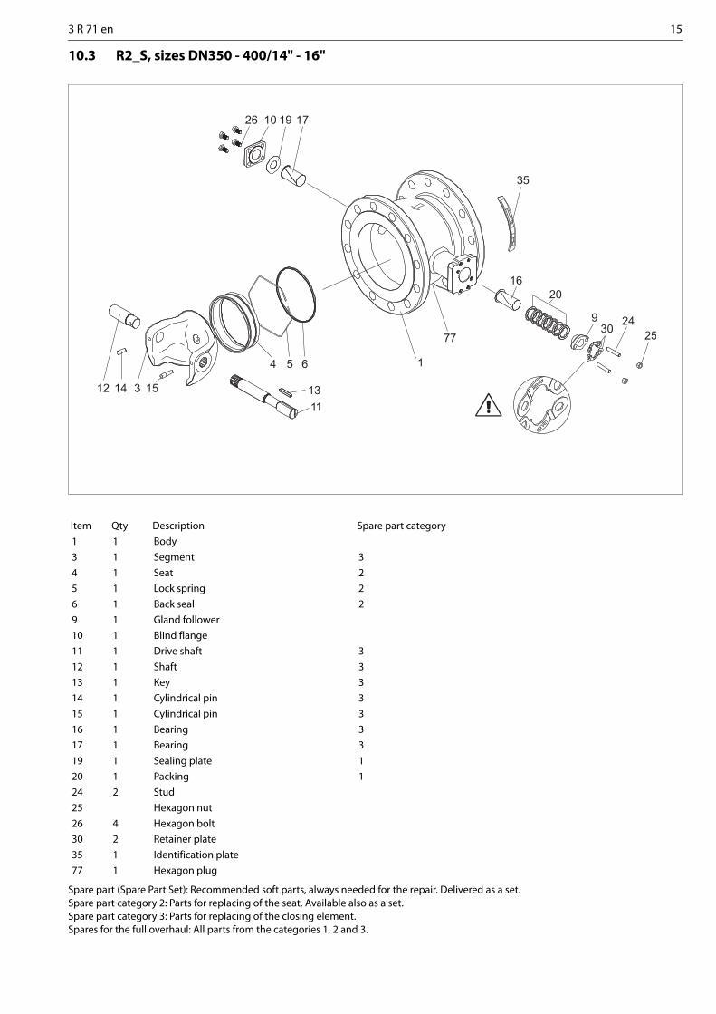
10.3 R2_S, sizes DN350 - 400/14" - 16"
Spare part (Spare Part Set): Recommended soft parts, always needed for the repair. Delivered as a set.Spare part category 2: Parts for replacing of the seat. Available also as a set.Spare part category 3: Parts for replacing of the closing element.Spares for the full overhaul: All parts from the categories 1, 2 and 3.
Item Qty Description Spare part category1 1 Body3 1 Segment 34 1 Seat 25 1 Lock spring 26 1 Back seal 29 1 Gland follower10 1 Blind flange11 1 Drive shaft 312 1 Shaft 313 1 Key 314 1 Cylindrical pin 315 1 Cylindrical pin 316 1 Bearing 317 1 Bearing 319 1 Sealing plate 120 1 Packing 124 2 Stud25 Hexagon nut26 4 Hexagon bolt30 2 Retainer plate35 1 Identification plate77 1 Hexagon plug

16 3 R 71 en
11 DIMENSIONS
11.1 Series R1
* Low capacity segment: max Cv 0.5, 1.5, 5 or 15
DN MAIN DIMENSIONS, mm SHAFT DIMENSIONS, mmD A A1 B C S T U
UNCkg O E R M P N Dl
25 33/38* 50 25 64 57 70 - 3/8 2.5 15 144 70 4.76 17 25 1540 49 60 25 82 63 70 - 3/8 3.5 15 151 71 4.76 17 25 1550 60 75 32 100 92 70 - 3/8 5 15 170 70 4.76 17 25 1580 89 100 45 131 108 90 - 1/2 9 20 196 79 4.76 22.2 35 20
100 113 115 50 158 117 90 - 1/2 11 20 205 80 4.76 22.2 35 20150 164 160 65 216 177 110 32 1/2 26 25 295 110 6.35 27.8 46 25200 205 200 80 268 200 130 32 1/2 48 25/30 346 140 6.35 27.8 46 30250 259 240 92 326 252 130 32 1/2 78 35 390 141 9.52 39.1 58 35
DNDN
CCEE
Ø D
SSSS
Ø B
A 1
U UM
TT
DN 25...100 / 1"-4" DN 150...250 / 6"-10"
MM
NN
PP
OO
A
R
R1

3 R 71 en 17
R1L-B1C, B1J/B1JA
R1L-B1C
* Supply pressure 5 bar
R1L-B1J/B1JA
* Supply pressure B1J 4 bar / B1JA 5 bar
NPT
1/4 NPT
NPT
1/4 NPT
ø B
A
C J
F
SUPPLY
SIGN AL
TYPE Max.Δp
bar*
DIMENSIONS, mm NPT Kg
A B C F J
R1L25-B1C6 25 50 64 57 400 405 1/4 10
R1L40-B1C6 25 60 82 63 400 410 1/4 11
R1L50-B1C6 25 75 100 92 400 430 1/4 13
R1L80-B1C6 25 100 131 108 400 445 1/4 17
R1L100-B1C6 25 115 158 117 400 455 1/4 19
R1L150-B1C6R1L150-B1C9
1025
160160
216216
177177
400455
530525
1/41/4
3436
R1L200-B1C9R1L200-B1C11
1525
200200
268268
200200
455540
575590
1/43/8
5763
R1L250-B1C11R1L250-B1C13
1525
240240
326326
252252
540635
630645
3/83/8
95110
TYPE Max.Δpbar*
DIMENSIONS, mm NPT Kg
A B C F J
R1L25-B1J8/B1JA8 25/25 50 64 57 560 400 3/8 19
R1L40-B1J8/B1JA8 25/25 60 82 63 560 405 3/8 20
R1L50-B1J8/B1JA8 25/25 75 100 92 560 425 3/8 22
R1L80-B1J8/B1JA8 25/25 100 131 108 560 445 3/8 26
R1L100-B1J8/B1JA8 25/25 115 158 117 560 450 3/8 28
R1L150-B1J8/B1JA8R1L150-B1J10/B1JA10
10/2525/25
160160
216216
177177
560650
525535
3/83/8
4354
R1L200-B1J10/B1JA10R1L200-B1J12/B1JA12
15/2525/25
200200
268268
200200
650800
590605
3/81/2
75100
R1L250-B1J12/B1JA12R1L250-B1J16/B1JA16
20/2525/25
240240
326326
252252
800990
645680
1/21/2
130170

18 3 R 71 en
11.2 Series R21
R21
* Low capacity segment: max Cv 0.5, 1.5, 5 or 15Cv 100 % of 95° travel. The allowed pressure differential in closed position is 25 bar / 370 psi.
DN DIMENSIONS, mm SHAFT DIMENSIONS, mm FLANGE DIMENSIONS, mm
ASME 150 ASME 300
D A C S T UUNC
O E R M P N B b1 F kg B b1 F kg
25 33/38*
102 57 70 - 3/8 15 144 70 4.76 17 25 108 14.5 1.6 3.5 17.5 1.6 5
40 49 114 63 70 - 3/8 15 151 71 4.76 17 25 127 14.5 1.6 5 156 21 1.6 8
50 60 124 92 70 - 3/8 15 170 70 4.76 17 25 152 16 1.6 8 165 22.5 1.6 10
80 89 165 108 90 - 1/2 20 196 79 4.76 22.2 35 191 19.5 1.6 15 210 29 1.6 20
100 113 194 117 90 - 1/2 20 205 80 4.76 22.2 35 229 24 1.6 23 254 32 1.6 31
200 205 243 200 130 32 1/2 25/30 346 140 6.35 27.8 46 343 29 1.6 70 381 41.5 1.6 95
250 259 297 252 130 32 1/2 35 390 140 9.52 39.1 58 406 30.5 1.6 105 445 48 1.6 140
300 300 338 270 160 40 5/8 40 462 165 9.52 44.2 68 483 32 1.6 155 520 51 1.6 205
DN FLANGE DIMENSIONS, mm
R21J PN10 R21K PN16 R21L PN25 R21M PN40
B b1 f kg B b1 f kg B b1 f kg B b1 f k
25 115 18 2 4.5 115 18 2 4.5 115 18 2 4.5 115 18 2 4.5
40 150 18 3 7 150 18 3 7 150 18 3 7 150 18 3 7
50 165 20 3 10 165 20 3 10 165 20 3 10 165 20 3 10
80 200 20 3 16 200 20 3 16 200 24 3 17 200 24 3 17
100 220 20 3 21 220 20 3 21 235 24 3 24 235 24 3 24
200 340 24 3 65 340 24 3 65 360 30 3 75 375 34 3 85
250 395 26 3 100 405 26 3 105 425 32 3 115 450 38 3 130
300 445 26 4 135 460 28 4 145 485 34 4 160 515 42 4 185
DN FLANGE DIMENSIONS, mm
R21R JIS 10K R21S JIS 16K R21T JIS 20K
B b1 f kg B b1 f kg B b1 f kg
25 125 14 1 5 125 14 1 5 125 16 1 5
40 140 16 2 6 140 16 2 6 140 18 2 7
50 155 16 2 8 155 16 2 8 155 18 2 8
65 175 18 2 10 175 18 2 10 175 20 2 12
80 185 18 2 14 200 20 2 14 200 22 2 16
100 210 18 2 19 225 22 2 22 225 24 2 23
150 280 22 2 40 305 24 2 45 305 28 2 50
200 330 22 2 65 350 26 2 70 350 30 2 75
250 400 24 2 100 430 28 2 110 430 34 2 120
300 445 24 3 135 480 30 3 150 480 36 3 160
DN
CCEE
Ø DØ B
SSSSMM
UU UUMM
TT
R21_A NN
PP
O
f b1
AA
R21_A200Ø 25 / 1" Ø 30 /1.18"
R
R21
DN 200...400 / 8"-16"DN 25...100 / 1"-4"

3 R 71 en 19
R21-B1C, B1J/B1JA
R21-B1C
* Supply pressure 5 bar
R21-B1J/B1JA
* Supply pressure B1J 4 bar / B1JA 5 bar
NPT
1/4 NPT
NPT
1/4 NPT
ø B C
A
J
F
TYPE Max.Δp
bar*
DIMENSIONS, mm NPT R21JPN 10
R21KPN 16
R21LPN 25
R21MPN 40
R21CASME 150
R21DASME 300
A C F J ØB kg ØB kg ØB kg ØB kg ØB kg ØB kg
R21_25-B1C6 25 102 57 400 405 1/4 115 9 115 9 115 9 115 9 108 8 124 9
R21_40-B1C6 25 114 63 400 410 1/4 150 11 150 11 150 11 150 11 127 9 156 12
R21_50-B1C6 25 124 92 400 430 1/4 165 14 165 14 165 14 165 14 152 12 165 14
R21_80-B1C6 25 165 108 400 445 1/4 200 20 200 20 200 21 200 21 191 19 210 24
R21_100-B1C6 25 194 117 400 455 1/4 220 25 200 25 235 28 235 28 229 27 254 35
R21_200-B1C9R21_200-B1C11
1525
243243
200200
455540
575590
1/43/8
340340
7580
340340
7580
360360
8590
375375
95100
343343
8085
381381
105110
R21_250-B1C11R21_250-B1C13
1525
297297
252252
540635
630645
3/83/8
395395
115130
405405
120135
425425
130145
450450
150165
406406
125140
445445
160175
R21_300-B1C13R21_300-B1C17R21_350-B1C13
19259
338338400
270270310
635770635
695730710
3/81/23/8
445445505
165190215
460460520
175200225
485485555
190215255
515515580
215240290
483483534
185210240
520520584
235260310
TYPE Max.Δp
bar*
DIMENSIONS, mm NPT R21KPN 10
R21KPN 16
R21LPN 25
R21MPN 40
R21CASME 150
R21DASME 300
A C F J OB kg OB kg OB kg OB kg OB kg OB kg
R21_25-B1J8/B1JA8 25/25 102 57 560 400 3/8 115 21 115 21 115 21 115 21 108 20 124 21
R21_40-B1J8/B1JA8 25/25 114 63 560 405 3/8 150 23 150 23 150 23 150 23 127 21 156 24
R21_50-B1J8/B1JA8 25/25 124 92 560 425 3/8 165 26 165 26 165 26 165 26 152 24 165 26
R21_80-B1J8/B1JA8 25/25 165 108 560 445 3/8 200 32 200 32 200 33 200 33 191 31 210 36
R21_100-B1J8/B1JA8 25/25 194 117 560 450 3/8 220 37 220 37 235 40 235 40 229 39 254 47
R21_200-B1J10/B1JA10R21_200-B1J12/B1JA12
15/2525/25
243243
200200
650800
590605
3/81/2
340340
95115
340340
95115
360360
105125
375375
115135
343343
100120
381381
125145
R21_250-B1J12/B1JA12R21_250-B1J16/B1JA16
20/2525/25
297297
252252
800990
645680
1/21/2
395395
150190
405405
155195
425425
165205
450450
185225
406406
160200
445445
195235
R21_300-B1J12/B1JA12R21_300-B1J16/B1JA16R21_300-B1J16/B1JA16
8/1820/2525/25
338338338
270270270
800990
1200
695730765
1/21/23/4
445445445
185225295
460460460
195235305
485485485
210250320
515515515
235275345
483483483
205245315
520520520
255295365

20 3 R 71 en
11.3 Series R2_S
Valve size
MAIN DIMENSIONS, mmDN D A C E S T O R M P N U
UNCPlugNPTF
80/100 80 102 165 108 196 90 - 20 79 4.8 22.2 35 1/2 1/2100/150 100 136 163 117 205 90 - 20 80 4.8 22.2 35 1/2 1/2150/200 150 190 207 177 295 110 32 25 110 6.4 27.8 46 1/2 1/2200/250 200 240 248 200 346 130 32 25 140 6.4 27.8 46 1/2 3/4250/300 250 296 297 250 390 130 32 35 141 9.5 39.1 58 1/2 3/4300/350 300 336 338 270 462 160 40 40 165 9.5 44.2 68 5/8 3/4350/400 350 390 400 311 513 160 40 45 200 12.7 50.4 80 M16 3/4400/450 400 450 400 353 584 160 55 50 230 12.7 55.5 90 M20 3/4
DN 150...400DN 80...100S U U
T
S
Ø B2
Ø D
Ø B1
f b 1
E
O
M
C
N
P
O
DN
f b2
A
R
R2_S
SIZEFLANGE DIMENSIONS, mm
R2JS PN 10 R2KS PN 16 R2LS PN 25 R2MS PN 40B1 b B2 b2 F kg B1 b B2 b2 F kg B1 b B2 b2 F kg B1 b B2 b2 F kg
80/100 200 20 220 20 3 16 200 20 220 20 3 16 200 24 235 24 3 18 - - - - - -100/150 220 20 285 22 3 24 220 20 285 22 3 24 235 24 300 28 3 30 - - - - - -150/200 285 22 340 24 3 43 285 22 340 24 3 43 300 28 360 30 3 52 - - - - - -200/250 340 24 395 26 3 68 340 24 405 26 3 69 360 30 425 32 3 80 - - - - - -250/300 395 26 445 26 3 98 405 26 460 28 3 100 425 32 485 34 3 110 - - - - - -300/350 445 26 505 26 4 165 460 28 520 30 4 175 485 34 555 38 4 195 - - - - - -350/400 505 26 565 26 2 166 520 30 580 32 2 177 555 38 620 40 2 206 580 46 660 50 2 244400/450 565 26 615 28 2 201 580 32 640 40 2 224 620 40 670 46 2 256 660 50 685 57 2 298
SIZEFLANGE DIMENSIONS, mm
R2CS ASME 150 R2DS ASME 300B1 b B2 b2 F kg B1 b B2 b2 F kg
80/100 191 19.5 229 24.0 1.6 17 210 24 254 24 2 19100/150 229 24.0 279 25.5 1.6 27 254 24 318 28 2 30150/200 279 25.5 343 29.0 1.6 46 318 28 381 34 2 50200/250 343 26.0 406 30.5 1.6 74 381 34 450 38 2 82250/300 406 30.6 483 32.0 1.6 105 450 38 521 42 2 115300/350 483 32.0 534 35.0 1.6 185 521 42 584 42 2 190350/400 535 35.4 595 37 2 192 585 54.4 650 57.6 2 257400/450 595 37 635 40.1 2 230 650 57.6 710 60.8 2 315
SIZEFLANGE DIMENSIONS, mm
R2RS JIS 10 K R2SS JIS 16 K R2TS JIS 25 KB1 b1 B2 b2 f kg B1 b1 B2 b2 f kg B1 b1 B2 b2 f kg
80/100 185 18 210 18 2 14 - - - - - - - - - - - -100/150 210 18 280 22 2 23 - - - - - - - - - - - -150/200 280 22 330 22 2 41 - - - - - - - - - - - -200/250 330 22 400 24 2 65 - - - - - - - - - - - -250/300 400 24 445 24 2 98 - - - - - - - - - - - -300/350 445 24 490 26 3 165 - - - - - - - - - - - -350/400 490 26 560 28 3 159 540 34 605 38 3 192 540 40 605 46 3 201400/450 560 28 620 30 3 201 605 38 675 40 3 247 605 46 675 48 3 260

3 R 71 en 21
R2_S-B1C, B1J/B1JA
R2_S-B1C
R2_S-B1J/B1JA
TYPE DIMENSIONS, mm NPT NPTF kg
DN A C D F G X V J H I
R2_S 80/100-BC 9 80 165 108 102 455 315 110 43 221 405 220 1/4 1/2 30
R2_S100/150-BC 9 100 163 117 136 455 315 110 43 229 425 220 1/4 1/2 42
R2_S150/200-BC11 150 207 177 190 540 375 135 51 310 570 225 3/8 1/2 69
R2_S200/250-BC13 200 248 200 240 635 445 175 65 367 665 235 3/8 3/4 113
R2_S250/300-BC17 250 298 252 296 700 470 175 78 420 760 260 1/2 3/4 170
R2_S300/350-B1C17 300 338 270 336 770 545 215 78 495 880 340 1/2 3/4 230
R2_S350/400-B17 350 400 311 390 770 545 215 78 582 1000 340 1/2 3/4 260
R2_S350/400-B20 350 400 311 390 840 575 215 97 601 1020 355 1/2 3/4 279
R2_S400/450-B25 400 400 353 450 1040 710 265 121 691 1177 390 1/2 3/4 387
TYPE DIMENSIONS, mm NPT NPTF kg
DN A C D F G X V J H I
R2_S 80/100-B1J10 80 165 108 102 640 480 175 51 225 420.5 225 3/8 1/2 48
R2_S 100/150-B1J10 100 163 117 136 640 480 175 51 234 438.5 225 3/8 1/2 60
R2_S 150/200-B1J12 150 207 177 190 815 620 215 65 330 614.5 235 1/2 1/2 109
R2_S 200/250-B1J16 200 248 200 240 990 760 265 78 396 728.5 340 1/2 3/4 180
R2_S 250/300-B1J20 250 298 252 296 1230 940 395 97 447 896.5 355 3/4 3/4 285
R2_S 300/350-B1J20 300 338 270 336 1230 940 395 97 509 976.5 355 3/4 3/4 370
R2_S 350/400-B1J20 350 400 311 390 1230 940 395 97 548 1056.5 355 3/4 3/4 419
R2_S 400/450-B1J25 400 400 353 450 1490 1140 505 121 632 1237.5 390 3/4 3/4 648
NPTF
FLOW DIRECTION
NPT
NPT
I
X
G
F
C J
H
V
A
DN
øD
Plug forflushing
22 3 R 71 en
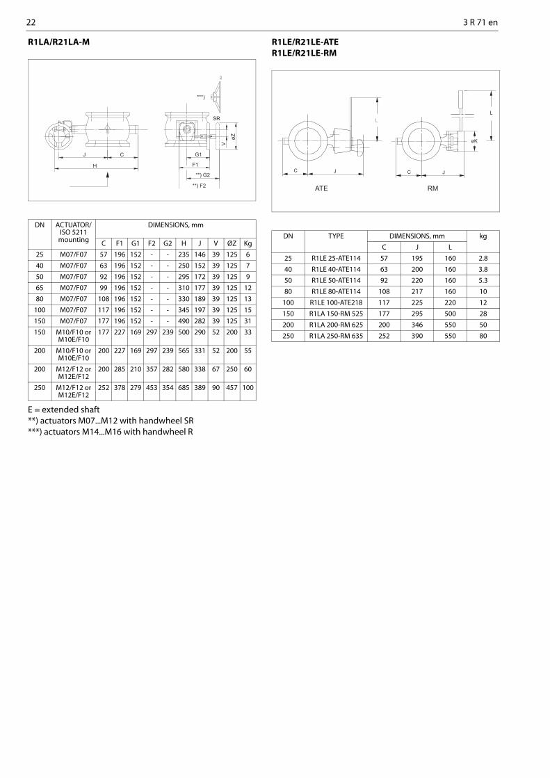
R1LA/R21LA-M
E = extended shaft**) actuators M07...M12 with handwheel SR***) actuators M14...M16 with handwheel R
R1LE/R21LE-ATER1LE/R21LE-RM
DN ACTUATOR/ISO 5211
mounting
DIMENSIONS, mm
C F1 G1 F2 G2 H J V ØZ Kg
25 M07/F07 57 196 152 - - 235 146 39 125 6
40 M07/F07 63 196 152 - - 250 152 39 125 7
50 M07/F07 92 196 152 - - 295 172 39 125 9
65 M07/F07 99 196 152 - - 310 177 39 125 12
80 M07/F07 108 196 152 - - 330 189 39 125 13
100 M07/F07 117 196 152 - - 345 197 39 125 15
150 M07/F07 177 196 152 - - 490 282 39 125 31
150 M10/F10 orM10E/F10
177 227 169 297 239 500 290 52 200 33
200 M10/F10 orM10E/F10
200 227 169 297 239 565 331 52 200 55
200 M12/F12 orM12E/F12
200 285 210 357 282 580 338 67 250 60
250 M12/F12 orM12E/F12
252 378 279 453 354 685 389 90 457 100
J C
H
G1
F1
**) G2
**) F2
SR
***)
V
øZDN TYPE DIMENSIONS, mm kg
C J L
25 R1LE 25-ATE114 57 195 160 2.8
40 R1LE 40-ATE114 63 200 160 3.8
50 R1LE 50-ATE114 92 220 160 5.3
80 R1LE 80-ATE114 108 217 160 10
100 R1LE 100-ATE218 117 225 220 12
150 R1LA 150-RM 525 177 295 500 28
200 R1LA 200-RM 625 200 346 550 50
250 R1LA 250-RM 635 252 390 550 80
øK
L
C JJC
ATE RM

3 R 71 en 23
12 TYPE CODE
Examble codes:R1 L A 100 T T T U - - / -R2 1 L A 100 T T T U F - / -R2 1 C A 04 T T T U T - / -R2 L S 100/150 C J J K V - / -
V-port segment valve, series R1, R21 and R2_S1. 2. 3. 4. 5. 6. 7. 8. 9. 10. 11. 11. 12.
R2 1 L A 100 T T T U T - /
1. CV-CODE FOR VALVE SIZE 01STANDARD Cv
Without signNON-STANDARD Cv
C005 Max. Cv = 0.5C015 Max. Cv = 1.5C05 Max. Cv = 5C15 Max. Cv = 15
2. PRODUCT SERIESR1 Flangeless, reduced boreR2 Flanged, reduced bore
3. FACE-TO-FACE DIMENSIONSFace-to-face length Neles factory standard, without sign
1 ISA S 75.04 and DIN/IEC 534 Teil 3-2
4. PRESSURE RATINGJ PN 10, flanged R21K PN 16, flanged R21L PN 25, flanged R21; flangeless R1M PN 40, flanged R21C ASME 150, flanged R21D ASME 300, flanged R21R JIS 10K, flanged R21S JIS 16K, flanged R21T JIS 20K, flanged R21
5. CONSTRUCTIONA Standard R1LA or R21_AS High-consistency version R2_S flangedY Special
6. SIZER1L
025, 040, 050, 065, 080, 100, 150, 200, 250
01, 1H, 02, 2H, 03, 04, 06, 08, 10R21
025, 040, 050, 080, 100, 200, 250, 300
01, 1H, 02, 03, 04, 08, 10, 12R2_S
080/100, 100/150, 150/200, 200/250, 250/300, 300/350, 350/400, 400/450
03/04, 04/06, 06/80, 08/10, 10/12, 12/14, 14/16, 16/18
7. BODY SCREWSA CF8M A4-80 / B8MC CG8M A4-80 / B8MD WCB A4-80 / B8MT Titanium TitaniumU CK3MCuN A4-70/B8MY Special Special
8. SEGMENTC CG8M + chromiumH Hastelloy CJ AISI 329 + chromiumK W. no. 1.4408 + chromiumL W. no. 1.4308/1.4306 + chromiumT Titanium + ceramic coatingR CG8MS AISI 329Y Special
9. SHAFTS, PINS/BEARINGSJ AISI 329 / PTFEH Hastelloy C / PVDFN Nitronic 50 / PTFET Titanium / PVDFY Special
10. SEATK Metal seat, general serviceS Stellite, back seal PTFE lipsealE Stellite, erosion resistant version, non-tightU Titanium, back seal Viton GFT PTFE + C25%, metal bodyY Special
11. OTHER PARTSF Graphite gland packing T Live loaded PTFE V-ring packingG Live loaded graphite packing V V-ring packing, PTFE Y Special, to be specified
12. FLANGE FACING- EN 1092-1 Type B1 (Ra 3.2 - 12.5), without sign.

24 3 R 71 en
Metso Flow Control Inc.
Europe, Vanha Porvoontie 229, P.O. Box 304, FI-01301 Vantaa, Finland. Tel. +358 20 483 150. Fax +358 20 483 151North America, 44 Bowditch Drive, P.O. Box 8044, Shrewsbury, M A 01545, USA. Tel. +1 508 852 0200. Fax +1 508 852 8172
South America, Av. Independéncia, 2500-Iporanga, 18087-101, Sorocaba-São Paulo, Brazil. Tel. +55 15 2102 9700. Fax +55 15 2102 9748 Asia Pacific, 238B Thomson Road, #17-01 Novena Square Tower B, Singapore 307685. Tel. +65 6511 1011. Fax +65 6250 0830
China, 11/F, China Youth Plaza, No.19 North Rd of East 3rd Ring Rd, Chaoyang District, Beijing 100020, China. Tel. +86 10 6566 6600. Fax +86 10 6566 2583Middle East, Roundabout 8, Unit AB-07, P.O. Box 17175, Jebel Ali Freezone, Dubai, United Arab Emirates. Tel. +971 4 883 6974. Fax +971 4 883 6836
www.metso.com/valves