V International PhD Student Workshop on Durability of Reinforced Concrete. From Composition to
182
V International PhD Student Workshop on Durability of Reinforced Concrete From Composition to Service Life Design • V I S I O N S • S C I E N C E • T E C H N O L O G Y • R E S E A R C H H I G H L I G H T S 65
Transcript of V International PhD Student Workshop on Durability of Reinforced Concrete. From Composition to

V International PhD Student Workshop on Durability of Reinforced ConcreteFrom Composition to Service Life Design
•VISIONS•S
CIE
NC
E•T
ECHNOLOGY•R
ES
EA
RC
HHIGHLIGHTS
65


VTT TECHNOLOGY 65
V International PhD Student Workshop on Durability of Reinforced Concrete From Composition to Service Life Design
Rui Miguel Ferreira VTT Technical Research Centre of Finland, Espoo, Finland & C-TAC, University of Minho Guimarães, Portugal
Joost Gulikers Rijkswaterstaat – Centre for Infrastructure Utrecht, The Netherlands
Carmen Andrade Research Centre for Safety and Durability of Materials and Structures CISDEM-UPM-CSIC Madrid, Spain

ISBN 978-951-38-7899-3 (soft back ed.) ISSN 2242-1211 (soft back ed.)
ISBN 978-951-38-7900-6 (URL: http://www.vtt.fi/publications/index.jsp) ISSN 2242-122X (URL: http://www.vtt.fi/publications/index.jsp)
Copyright © VTT 2012
JULKAISIJA – UTGIVARE – PUBLISHER
VTT PL 1000 (Tekniikantie 4 A, Espoo) 02044 VTT Puh. 020 722 111, faksi 020 722 7001
VTT PB 1000 (Teknikvägen 4 A, Esbo) FI-02044 VTT Tfn +358 20 722 111, telefax +358 20 722 7001
VTT Technical Research Centre of Finland P.O. Box 1000 (Tekniikantie 4 A, Espoo) FI-02044 VTT, Finland Tel. +358 20 722 111, fax + 358 20 722 7001
Kopijyvä Oy, Kuopio 2012

3
Preface This series of International PhD Student Workshops were started under the edu-cational activities of RILEM (Educational Activities Committee, EAC) and within the scope of the RILEM TC 213–MAI. The workshops have been held in various locations across Europe: Madrid-Spain (2007, 2010), Zagreb-Croatia (2008), Guimarães-Portugal (2009) and now Espoo-Finland (2012).
The objectives of the workshop were to bring together several PhD students, ei-ther just starting or well advanced in their study, from the same field of research in contact with each other, and promote a scientific dialogue between them. This achievement has helped the students to become more familiar with the presenta-tion of their research activities. In addition, many technical discussions on topics of interest were generated, stimulating the exchange of points of view in a relaxed and informal environment.
This workshop reflects the multi-disciplinary approach with which the durability of reinforced concrete structures is been tackled. Research varies from studying ad-vanced materials for concrete durability to the effects of climate change on deteriora-tion of structures. Other aspects addressed include assessment of repairs for rein-forced concrete structures, the performance of concrete with cracking, the service life assessment of existing reinforced concrete structures, and the modelling of chlo-ride ingress and the integrated effect of deterioration mechanisms.
It is our hope that this workshop has been useful to the participants and that it has helped them to become also aware of other aspects related to their work, and to the durability of concrete in general.
We would like to thank all the participants in the Workshop, for preparing and presenting their papers.
November 2012
Rui Miguel Ferreira, Joost Gulikers and Carmen Andrade
Editors

4
In the back (left to right): Miguel Ferreira, Zhengtian Song, Joost Gulikers, Christian Christodoulou, Lurdes Silva, Toni Pakkala, Andrjia Blagojević, Arto Köliö, Tapio Vehmas & Erika Holt.
In the front (left to right): Carmen Andrade, Fabiano Tavares, Zhengtian Yang, Renée Mors, Branko Šavija & Fahim Al-Neshawy.

5
Contents Preface ............................................................................................................. 3
Synthesis of modified hydrotalcites and preliminary evaluation of their corrosion protection effectiveness for reinforced concrete .................... 6
Advanced materials for concrete durability: Study of crystal growth modification with coated silicon carbide whiskers ................................ 18
Investigations on the incipient anode phenomenon following patch repairs for reinforced concrete structures ............................................. 24
Bacteria-based self-healing concrete – an introduction ............................... 32
Modelling chloride diffusion in cracked concrete: a lattice approach .......... 40
Studies on electrochemical lithium migration for remediation of Alkali-Silica Reaction at macro level in concrete structures .................. 50
Effects of climate change on deterioration of structures and repair need of existing building stock in Finland .............................................. 63
Research plan on the service life of existing concrete structures ............... 72
Impact of cracks on chloride-induced corrosion and durability of reinforced concrete structures – a literature review .............................. 80
Numerical modelling of chloride ingress through cracked concrete ........... 92
Effect of different repair techniques on the hygrothermal performance of concrete facades ......................................................... 107
Effect of supplymentary cements on minimising chloride ingress in high performance concrete ............................................................... 122
Corrosion data interpretation in concrete structures ................................. 132
Service life design of concrete subject to frost attack and carbonation/ chloride penetration .............................................................................. 142
Challenges facing innovations in corrosion control for sustainable RC constructions .................................................................................. 162

Synthesis of modified hydrotalcites and preliminary evaluation of their corrosion protection effectiveness for reinforced concrete
6
Synthesis of modified hydrotalcites and preliminary evaluation of their corrosion
protection effectiveness for reinforced concrete
Z. Yang, H. Fischer Materials innovation institute (M2i), Delft, The Netherlands
Materials and Environment, Faculty of Civil Engineering and Geosciences, Delft, The Netherlands
R. Polder
Materials and Environment, Faculty of Civil Engineering and Geosciences, Delft, The Netherlands
TNO Building Materials, Delft, The Netherland
ABSTRACT: Two modified hydrotalcites (MHTs) intercalated with nitrate and aminoben-zonate anions, (i.e., CaAl-MHT-NO3 and CaAl-MHT-pAB) have been synthesized. The intercalation of CaAl-MHT-pAB was achieved by anion exchange of nitrate in the host material, CaAl-MHT-NO3, which was prepared by a coprecipi-tation method. Materials characterization was conducted by means of X-ray dif-fraction (XRD), IR-spectroscopy and thermal analysis. The results of thermal anal-ysis combined with total organic carbon (TOC) analysis further confirmed p-aminobenzonate anion was successfully intercalated into the interlayer space of MHTs with a 33.1% intercalating rate. Volhard’s titrimetric analysis demonstrated that ion exchange occurred between free chloride ions in the simulated concrete pore solution and ions intercalated in MHTs. The preliminary results reported in this paper shed light on the promising use of MHTs as a new type of additive for improved corrosion protection of reinforced concrete.
1. Introduction
The use of reinforcing steel to improve the tensile properties of concrete has been an accepted practice for many years. The combination of steel and concrete is a composite which exhibits the best performance when the two materials are bond-ed together. The matrix material, concrete, however is porous and highly hetero-geneous. Exposed to service environment, the durability of concrete can be com-promised by the ingress of water with dissolved corrosive ions, chlorides, and other deleterious species which cause corrosion of the reinforcing steel. This oc-curs via deterioration of the passivation layer of the steel, present only at high pH values. Additionally, freeze-thaw cycles in cold climates may also undermine the protection of reinforcement. All of these factors potentially impose a serious threat
Synthesis of modified hydrotalcites and preliminary evaluation of their corrosion protection effectiveness for reinforced concrete
7
on the durability and serviceability of concrete structures (Bertolini et al. 2004, Gaal 2004, Shi et al. 2010). Typically present in de-icing salts and marine envi-ronment, chlorides penetration has been recognized as a critical process affecting the durability of reinforced concrete (Polder 2009, Yang et al. 2009).
Traditional standards oversimplify the complexity of the mechanisms involved and consequently, modern service life design approaches mainly aim at providing sufficient concrete cover depth to the reinforcing steel. New generation reinforce-ment such as stainless steel is much more expensive than ordinary reinforcing (carbon) steel (Cigna et al. 2002, Elsener et al. 2010). Cathodic prevention or protection may be also effective; however both are a special niche expertise and are thus not applied on a wide scale (Pedeferri 1996). Coatings on the concrete surface are not able to guarantee a long enough protection (10–20 years), which causes the need of a cycle of maintenance of its own (Cigna et al. 2002). The application of corrosion inhibitors has been proposed but they are generally not reliable in terms of long-term efficiency (Elsener 2001)
In the last two decades, more effort was focussed on the development of new or modified compounds able to prevent or stop corrosion and other durability related issues (Elsener 2001, Tatemastu and Sasaki 2003, Raki et al. 2004). The applica-tion of modified hydrotalcites (MHTs) may represent a promising strategy for use in concrete with the purpose to improve corrosion resistance. The MHTs’ structure represented by a general formula [MII
1-xMIIIx(OH)2]x+ [(An-
x/n)]x-·mH2O can accommo-date various cations in the hydroxide layers with varying MII/MIII ratios as well as a great variety of anionic species in the interlayer regions. The x value is in the range 0.22–0.33. A key feature of MHTs is their high anionic exchange capacity (2 to 4.5 milliequivalents/g) which makes exchange of the interlayer ion by a wide range of organic or inorganic anions versatile and easily achieved (Meyn et al. 1990). Hy-drotalcite or hydrotalcite-like phases have been found in hydrated slag cements, which are known to bind more chloride ions than pure Portland cements (Dhir et al.1996, Arya and Xu 1995, Glass and Buenfeld 2000). The existence of hy-drotalcite-like phases such as Friedl’s salt (a chloride-bearing AFm phase) or its iron analogue and/or Kuzel’s salt (a chloride- and sulfate-bearing AFm phase) have been believed to contribute to chloride binding and thus enhance the corrosion resistance of reinforced concrete (Birnin-Yauri and Glasser 1998). The beneficial effects of Friedl’s salt on binding chloride in cement support the idea of using MHTs in con-crete as an effective chloride scavenger and the increased binding would definitely slow down chloride transport through concrete matrix. For the envisaged use as an additive to concrete against chloride attack, certain inorganic or organic anions with known inhibitive properties could be intercalated in the structures of MHTs, which then can be slowly released, possibly 'automatic' upon arrival of chloride ions. Such inhibition would also increase the chloride threshold level for corrosion initiation and/or reduce the subsequent corrosion rate of the reinforce steel in concrete. The anion exchange process can be described according to the following Equation 1:
HT-Inh + Cl-(aq) ® HT-Cl + Inh-(aq) (1)
where Inh- represents the intercalated inorganic or organic inhibitive anions.

Synthesis of modified hydrotalcites and preliminary evaluation of their corrosion protection effectiveness for reinforced concrete
8
This paper reports on the synthesis of a calcium aluminate-based MHT as a model material and experiments designed to investigate the feasibility of MHTs with the selected intercalating inorganic or organic molecules of relevance to be able to act as a scavenger for chloride. The primary objective of the paper is there-fore to provide preliminary information to explore the promising use of the other various MHTs compositions with selected intercalating inhibitive anions suitable for additives for concrete with a perspective view to reduce chloride-induced cor-rosion of reinforced concrete.
2. Experimental
2.1 Materials and synthesis
Ca(NO3)2·4H2O, Al(NO3)3·9H2O and NaNO3 were obtained from Merck KGaA. NaOH, p-aminobenzonoic acid (pABA) and p-aminobenzonate sodium salt were obtained from Sigma-Aldrich. All reagents are ACS grade (>99% purity) and used as received without further purification. Boiled distilled water was used for the preparation of aqueous solution and filtration.
2.1.1 Preparation of CaAl-MHT-NO3
The CaAl-MHT-NO3 was synthesized by a pH-controlled coprecipitation synthetic method as described elsewhere (Meyn et al. 1990, Millange et al. 2000). Typically, 66.1g Ca(NO3)2·4H2O and 45g of Al(NO3)3·9H2O were mixed together in 320 ml of water and then the solution was added dropwise within 1.0 hour to a solution of 24g of NaOH and 34g of NaNO3 in 290 ml of water under vigorous stirring and N2 atmosphere. Once addition was completed, the resulting suspension was main-tained at 65°C for 16–18 hours under vigorous stirring, after which the solid precip-itate was collected and washed thoroughly with boiled distilled water. The product was then dried for 16–18 hours at 105°C under vacuum.
2.1.2 Preparation of CaAl-MHT-pAB
The intercalation of p-aminobenzoate was carried out using anion exchange reac-tions as previously reported studies (Raki et al. 2004, Millange et al. 2000, Perioli et al. 2006). Typically, 5.0 g of the CaAl-MHT-NO3 is dispersed in 500 ml 0.1 M aqueous solutions of 4-aminobenzoate sodium salt. The mixtures were allowed to react for 16 hours under N2 atmosphere and vigorous stirring at 65–70°C. The organic derivatives were isolated by filtration. After being washed thoroughly with boiled distilled water, the solid product was then dried under vacuum for 4 h at 105°C.

Synthesis of modified hydrotalcites and preliminary evaluation of their corrosion protection effectiveness for reinforced concrete
9
2.2 Characterisation
X-ray powder diffraction (XRD) was performed on a Bruker D5005 diffractometer equipped with Huber incident-beam monochromator and Braun PSD detector using Cu Kα radiation in the 2θ region between 5 and 90°. Thermal analyses on powder samples were carried out using a NETZSCH STA 449 F3 Jupiter® simul-taneous thermal analyzer TG/DSC under flowing Argon (50 ml/min) at a heating rate of 10 K/min from 40 to 1100°C. FT-IR spectra were recorded using a Perkin–Elmer Spectrum 100 Series spectrometer equipped with universal Attenuated Total Reflexion (ATR) unit over the wave number range of 4 000 to 6 000 cm−1. The samples were scanned 32 times each time with 4 cm−1 resolution. Shimadzu TOC-VCPH total organic carbon analyzer and a spectrophotometer (Spectroquant®
Nova 60, Merck Genmany) were employed respectively to analyze the intercala-tion rate of the corresponding organic anions and nitrate after dissolution of a known amount of intercalation compound in dilute HCl solution. Duplicate tests were conducted with the specimen involved.
2.3 Ion exchange behaviour of MHTs in alkaline chloride solutions
Ion exchange of MHTs with chloride was carried out in 0.1 M NaOH solution simu-lating the alkaline pore liquid of concrete. Two different chloride concentrations (i.e., 0.1 M and 1.0 M NaCl solutions) were selected. The two selected chloride concentrations are to represent the practical experience: the first value is close to the lower chloride critical threshold, which means corrosion of reinforcement would not occur, whilst the second value exceeds the critical range, which means the occurrence of corrosion conditions (Ormellese et al. 2009). Typically, a volume of 10 ml simulated pore solution with either of two selected chloride concentrations was mixed with 0.5g powder of MHTs respectively. The mixture was then put in a rotating device at room temperature for 24 hours to allow the occurrence of ion exchange of MHTs with chloride. Afterwards, the remaining solids were collected by centrifuging and washed thoroughly with boiled distilled water. For each sample, duplicates and blank solutions without mixing chloride were performed simultaneously. The chloride content in the remaining solid was determined by dissolution in nitric acid through Volhard’s titrimetric analysis.
3. Results and discussion
3.1 X-ray diffraction analysis
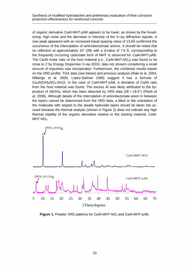
The diffraction patterns for the synthetic CaAl-MHT-NO3 as well as its organic derivative CaAl-MHT-pAB are shown in Figure 1. The diffraction pattern for CaAl-MHT-NO3 shows a typical layered structure with high crystallinity and a basal spacing d-value of 8.6Å comparable with those previously reported in the literature (Raki et al. 2004, Plank et al. 2006). Compared to CaAl-MHT-NO3, the crystallinity
Synthesis of modified hydrotalcites and preliminary evaluation of their corrosion protection effectiveness for reinforced concrete
10
of organic derivative CaAl-MHT-pAB appears to be lower, as shown by the broad-ening, high noise and the decrease in intensity of the X-ray diffraction signals. A new peak appeared with an increased basal spacing value of 13.6Å confirmed the occurrence of the intercalation of aminobenzonate anions. It should be noted that no reflection at approximately 10° (2θ) with a d-value of 7.6 Å, corresponding to the frequently occurring carbonate form of MHT is observed for CaAl-MHT-pAB. The Ca/Al molar ratio of the host material (i.e., CaAl-MHT-NO3) was found to be close to 2 by Energy Dispersive X-ray (EDX, data not shown) considering a small amount of impurities was incorporated. Furthermore, the combined results based on the XRD profile, TGA data (see below) and previous analysis (Raki et al. 2004, Millange et al. 2000, López-Salinas 1996) suggest it has a formula of Ca2Al(OH)6NO3·2H2O. In the case of CaAl-MHT-pAB, a deviation of Ca/Al ratio from the host material was found. The excess Al was likely attributed to the by-product of Al(OH)3 which has been detected by XRD data (2θ = 18.5°) (Plank et al. 2006). Although details of the intercalation of aminobezonate anion in between the layers cannot be determined from the XRD data, a tilted or flat orientation of the molecules with respect to the double hydroxide layers should be taken into ac-count because the thermal analysis (shown in Figure 2) does not indicate any high thermal stability of the organic derivative relative to the starting material, CaAl-MHT-NO3.
Figure 1. Powder XRD patterns for CaAl-MHT-NO3 and CaAl-MHT-pAB.
5 10 15 20 25 30 35 40 45 50 55 60 65 70
2Theta/degrees
CaAl-MHT-NO3
CaAl-MHT-pAB(003), d=13.6Å
(003), d=8.6Å

Synthesis of modified hydrotalcites and preliminary evaluation of their corrosion protection effectiveness for reinforced concrete
11
3.2 Thermal analysis
The thermal behaviors of intercalation compounds were investigated and the thermogravimetric analysis (TGA) curves and diffraction scanning calorimetry (DSC) thermograms are represented in Figure 2. For the CaAl-MHT-NO3, three major mass losses of 6.8% from 40 to 230°C, 14.7% between 230 and 450°C and 19.8% beyond 450°C can be observed. The corresponding DSC thermograms show three main features associated with the three mass losses. The first initial reduction in weight corresponds to physisorbed and interlayer water. The second weight loss results from a concomitant dehydroxylation (i.e., structural water) of the inorganic layers and a reduction of nitrates to nitrites (Plank et al. 2006, López-Salinas 1996). The third weight loss is caused by a further condensation of hy-droxyls including a collapse of the layered structures and decomposition of nitrites as reported elsewhere (López-Salinas 1996). The intercalated nitrate content was further determined by photometric analysis. 16.4% of nitrate was detected out of the gross mass of intercalation compound, CaAl-MHT-NO3 and this value is com-parable to the weight loss in the TGA curve which accounts for a concomitant dehydroxylation of the inorganic layers and the decomposition of nitrate. A possible reaction involved in such processes is shown as Equation 2 below:
2 6 3 2 2 2 xCa Al(OH) NO Ca AlO(OH) 2H O NO® + + (2)
In the case of CaAl-MHT-pAB, a similar trend of mass loss including three major effects was observed. The first weight loss in the range of 40 to 230°C is meas-ured as 10.6%. The second weight loss of 23.9% was observed between 230 and 500°C. The higher percentage of the second mass loss for CaAl-MHT-pAB, when compared to the starting material, CaAl-MHT-NO3, is attributable to the decompo-sition of pAB molecules which is further confirmed by the associated DSC thermo-grams and TOC analysis. As can be seen in Figure 2 ((B) and (C)), the DSC ther-mogram of pABA showed a sharp endothermic peak at around 190°C relative to the melting point of pure crystalline substance. When compared to CaAl-MHT-pAB, a noticeable small weak peak instead of the sharp strong endothermic peak at around 190°C in the thermogram of the intercalation compound is a confirma-tion that the intercalation of pAB occurred. On the other hand, this small weak shoulder peak indicates the decomposition of pAB started in the first temperature range and contributes to a certain percentage of weight loss in the associated TGA curve. The darkening of the specimen after thermogravimetry further indi-cates decomposition of pAB molecules. The third weight loss caused by further decomposition of pAB and condensation of hydroxyls including a collapse of the layered structures was found to be 7.8%. The pAB content was confirmed by the TOC analysis after MHT destruction in acidic medium. 11.8% of pAB was detected out of the gross mass of intercalation compound, CaAl-MHT-pAB from TOC and this value is comparable to the second weight loss in the TGA curve which ac-counts for a concomitant dehydroxylation of the inorganic layers and the decom-position of pAB molecules. If we assume that the intercalation compound has a

Synthesis of modified hydrotalcites and preliminary evaluation of their corrosion protection effectiveness for reinforced concrete
12
formula of Ca2Al(OH)6(H2NC6H4COO)·2H2O derived from the starting material, Ca2Al(OH)6NO3·2H2O, then the pAB content is calculated to be 35.7%. Based on this assumption, the intercalating rate of pAB in this case is 33.1% which is in agreement with the corresponding XRD pattern with high noise (Figure 1).
Figure 2. TGA/DSC curves for (A) CaAl-MHT-NO3, (B) CaAl-MHT-pAB and (C) pABA.
3.3 Infrared analysis
FT-IR Spectra of CaAl-MHT-NO3 and CaAl-MHT-pAB are shown in Figure 3. For both CaAl-MHT-NO3 and CaAl-MHT-pAB, a broad band between 3 600 and 3 400 cm-1 are observed representing the stretching vibrations of the hydrogen-bonded hydroxyl group of both hydroxide layers and interlayer water and a peak at 1 361 cm-1 due to the nitrate group is observed in the case of CaAl-MHT-NO3 (Perioli et al. 2006). For CaAl-MHT-pAB, characteristic peaks of pAB were present in the spectrum at 1 521 cm-1 and 1 388 cm-1corresponding respectively to the asymmetric and symmetric stretching vibrations associated with -COO- in carboxylic acid salts. Furthermore, a characteristic peak for the -NH2 bending mode is observed at 1 607 cm-1 and the aromatic C = C stretching mode appears at 1588 cm-1. The presence of these peaks is comparable with previously reported studies (Perioli et
TGA/DSC-CaAl-MHT-NO3
556065707580859095
100
0 200 400 600 800 1000
Temperature/℃
Mas
s cha
nge/
%
-0.80-0.60-0.40-0.200.000.200.400.600.801.001.20
Hea
t flo
w/(μ
v/m
g)
TGA/% DSC/(μv/mg)
exo
A
TGA/DSC-CaAl-MHT-pAB
50556065707580859095
100
0 200 400 600 800 1000
Temperature/℃
Mas
s cha
nge/
%
-0.80-0.60-0.40-0.200.000.200.400.600.801.00
Hea
t flo
w/(μ
v/m
g)
TGA/% DSC/(μv/mg)
exo
B TGA/DSC-pABA
0102030405060708090
100
0 200 400 600 800 1000Temperature/℃
Mas
s cha
nge(
%)
-1.50
-1.00
-0.50
0.00
0.50
1.00
1.50
2.00
Hea
t flo
w (μ
v/m
g)
TGA/% DSC/(μv/mg)
exo
C

Synthesis of modified hydrotalcites and preliminary evaluation of their corrosion protection effectiveness for reinforced concrete
13
al. 2006, Hsueh 2003) and indicates that p-aminobenzoate anions have been intercalated into the structure of MHTs.
Figure 3. FT-IR Spectra of CaAl-MHT-NO3 and CaAl-MHT-pAB.
3.4 Ion-exchange in chloride alkaline solutions
The ion exchange behavior between the MHTs (i.e., CaAl-MHT-NO3 and CaAl-MHT-pAB) and chloride was studied in 0.1 M NaOH solution. The chloride loading (in mg per unit mass of MHTs) in remaining solids and the anion-exchange of MHTs (in molar ratio) were obtained respectively by the following equations Equation 3 and Equation 4 and the results are listed in Table 1:
- b
MHT
mCl loadingm
= (3)
int- int-A
- ( )
b cl
MHT A
m MAnion exchange ratiom W M
= (4)
Where mb (mg) is the bound chloride in the remaining solid MHTs; mMHT (g) is the mass of dry solid MHT (i.e., CaAl-MHT-NO3 and CaAl-MHT-pAB); Mcl (g/mol) is the molecular weight of chloride; Mint-A (g/mol) and Wint-A are the molecular weight of interlayer anion and its percentage content by mass of MHTs, respectively. It should be noted that Wint-A was calculated as 16.4% resulting from the photometric measurements in the case of CaAl-MHT-NO3, whilst 11.8% was used for CaAl-MHT-pAB according to the detected results of TOC analysis.

Synthesis of modified hydrotalcites and preliminary evaluation of their corrosion protection effectiveness for reinforced concrete
14
Table 1. Ion exchange of MHTs with chloride in simulated concrete pore solution.
Sample of synthetic MHTs used for chloride exchange in alkaline solution
Cl-loading in MHTs (mg/g)
Anion-exchange ratio of MHTs
0.1MNaCl+0.1MNaOH+CaAl-MHT-NO3 17.05 0.18
1.0MNaCl+0.1MNaOH+CaAl-MHT-NO3 82.45 0.88
0.1MNaCl+0.1MNaOH+CaAl-MHT-pAB 9.75 0.32
1.0MNaCl+0.1MNaOH+CaAl-MHT-pAB 11.57 0.38
As can be seen from Table 1, considerable ion-exchange indeed occurred be-tween the MHTs and the free chloride ions in simulated concrete pore solution containing a low or high chloride concentration. The results shown in Table 1, particularly of CaAl-MHT-NO3 are comparable with the other hydrotalcite-like compounds in nitrate form reported in the literature (Lv et al. 2009) in which the exchange reaction was conducted under the protection of N2 atmosphere in solu-tions with a lower chloride concentration. As for CaAl-MHT-pAB, however, when compared to CaAl-MHT-NO3, the chloride loading is relatively low, especially when chloride concentration is as high as 1.0 M. In terms of the molar ratio of anion exchange, it is interesting to see that the obtained values for CaAl-MHT-pAB are comparable to and even higher than those of CaAl-MHT-NO3, particularly when the chloride concentration is as low as 0.1 M. Considering the relatively low inter-calating ratio of pAB (33.1%, in this case) in MHTs, it is reasonable to believe that the use of CaAl-MHT-pAB as one kind of new additives in concrete for inhibiting chloride-induced corrosion is promising as long as the intercalating rate of pAB is increased by optimizing the techniques for synthesis. The overall lower values obtained for CaAl-MHT-pAB could be explained by either low content (11.8% by mass) of exchangeable pAB incorporated in the intercalation compound (see aforementioned thermal analysis section and TOC results) or by insufficient or non-optimum time for ion-exchange reactions. Nevertheless, it should be noted that the preliminary study reported in this paper did not take into account some factors that may influence the chloride exchange efficiency of the MHTs such as exchange time and temperature, pH effect of simulated solution and relationship between dosage of MHTs and chloride concentration. Individual or combination of these factors may significantly alter the chloride-uptake efficiency of the corre-sponding MHTs.
4. Conclusions
Two modified hydrotalcites intercalated with nitrate and aminobenzonate anions, (i.e., CaAl-MHT-NO3 and CaAl-MHT-pAB) have been synthesized and character-ized by means of XRD, TGA/DSC, IR and ESEM. TOC analysis and TGA results further confirmed p-aminobenzonate anion was successfully intercalated into the interlayer space of MHTs with a 33.1% intercalating rate of pAB. The preliminary

Synthesis of modified hydrotalcites and preliminary evaluation of their corrosion protection effectiveness for reinforced concrete
15
results from Volhard’s titrimetric analysis demonstrated that ion exchange indeed occurred between free chloride ions in simulated pore solution and nitrate or pAB anions intercalated in MHTs, thereby reducing the free chloride concentration, which is equivalent to increased binding of chloride present in concrete. Such results shed light on the promising use of MHTs as new additives for improved corrosion protection of reinforced concrete and are expected to contribute to the effort of searching for effective measures to improve the durability of reinforced concrete.
5. Acknowledgements
The research was carried out under the project number M81.609337 in the framework of the Research Program of the Materials innovation institute (M2i) (www.m2i.nl).
References
Arya, C. and Xu, Y. 1995. Effect of cement type on chloride binding and corrosion of steel in concrete. Cem. Conc. Res. 25(4), pp. 893–902.
Bertolini, L., Elsener, B., Pedeferri, P. and Polder, R.B. 2004. Corrosion of steel in concrete: Prevention, diagnosis, repair. Weinheim: Wiley-VCH.
Birnin-Yauri, U.A. and Glasser F.P. 1998. Friedel’s salt: Its solid solutions and their role in chloride binding. Cem. Concr. Res. 28(12), pp. 1713–1723.
Cigna, R., Andrade, C., Nürnberger, U., Polder, R., Weydert R. and E. Seitz (Eds.) 2002. COST 521: Final report. Luxembourg.
Dhir, R.K., El-Mohr, M.A.K. and Dyer, T.D. 1996. Chloride binding in GGBS con-crete. Cem. Conc. Res., 26(12), pp. 1767–1773.
Elsener, B. 2001. Corrosion Inhibitors for Steel in concrete-state of the art report. EFC Publication No. 35, London: IOM Communications.
Elsener, B., Addari, D., Coray, S. and Rossi, A. 2010. Stainless steel reinforcing bars-reason for their high pitting corrosion resistance. Mater. Corros. 61, pp. 1–9.
Gaal, G.C.M. 2004. Prediction of deterioration of concrete bridges. Ph.D. thesis, Delft: Delft University of Technology.
Synthesis of modified hydrotalcites and preliminary evaluation of their corrosion protection effectiveness for reinforced concrete
16
Glass, G.K. and Buenfeld, N.R. 2000. The influence of chloride binding on the chloride induced corrosion risk in reinforced concrete. Corros. Sci. 42(2), pp. 329–344.
Hsueh, H-B. and Chen, C.-Y. 2003. Preparation of properties of LDHs/Polyimide Nanocomposites. Polymer 44(4), pp. 1151–1161.
Lo´pez-Salinas, E., Llanos Serrano, M.E., Corte´s Ja´come, M.A. and Schifter Secora, I. 1996. Characterization of synthetic hydrocalumite-type: [Ca2AI(OH)6]NO3.mH2O: Effect of the calcination temperature. J. Porous Mater 2(4), pp. 291–297.
Lv, L., Sun, P., Gu, Z., Du, H., Pang, X., Tao, X., Xu, R. and Xu, L. 2009. Removal of chloride ion from aqueous solution by ZnAl-NO3 layered double hydrox-ides as anion-exchanger. J. Hazard. Mater. 161(2–3), pp. 1444–1449.
Meyn, M., Beneke, K. and Lagaly, G. 1990. Anion-exchange reactions of layered double hydroxides. Inorg. Chem. 29(26), pp. 5201–5207.
Millange, F., Walton, R., Lei, L. and O’Hare, D. 2000. efficient separation of ter-ephtalate and phtalate anions by selective ion-exchange intercalation in the layered double hydroxide Ca2Al(OH)6.NO3.2H2O. Chem. Mater. 12(7), pp. 1990–994.
Ormellese, M., Lazzari, L., Goidanich, S., Fumagalli, G. and Brenna, A. 2009. A study of organic substances as inhibitors for chloride-induced corrosion in concrete. Corros. Sci. 51(12), pp. 2959–2968.
Pedeferri, P. 1996. Cathodic protection and cathodic prevention. Constr. Bldg. Mater. 10(5), pp. 391–402.
Perioli, L., Ambrogia, V., Bertinia, B., Riccia, M., Nocchettib, M., Latterinib, L. and Rossia, C. 2006. Anionic clays for sunscreen agent safe use: Photopro-tection, photostability and prevention of their skin penetration. Eur. J. Pharm. Biopharm. 62(2), pp. 185–193.
Plank, J., Dai, Z. and Andres, P.R. 2006. Preparation and characterization of new Ca-Al-polycarboxylate layered double hydroxides”. Mater Lett 60(29–30), pp. 3614–3617.
Polder, R.B. 2009. Critical chloride content for reinforced concrete and its relation-ship to concrete resistivity. Mater. Corros. 60(8), pp. 623–630.

Synthesis of modified hydrotalcites and preliminary evaluation of their corrosion protection effectiveness for reinforced concrete
17
Raki, L., Beaudoin, J.J. and Mitchell, L. 2004. layered double hydroxide-like mate-rials: Nanocomposites for use in concrete. Cem. Conc. Res. 34(9), pp. 1717–1724.
Shi, X., Fay, L., Peterson, M.M. and Yang, Z. 2010. Freeze-thaw damage and chemical change of a portland cement concrete in the presence of diluted deicers. Mater Struct 43(7), pp. 933–946.
Tatematsu, H. and Sasaki, T. 2003. Repair Materials System for Chloride-induced Corrosion of Reinforcing Bars. Cem. Conc. Res. 25(1), pp. 123–129.
Yang, Z., Shi, X., Creighton, A.T. and Peterson, M.M. 2009. Effect of Styrene-Butadiene Rubber Latex on the Chloride Permeability and Microstructure of Portland Cement Mortars. Constr. Bldg. Mater. 23(6), pp. 2283–2290.
Advanced materials for concrete durability: Study of crystal growth modification with coated silicon carbide whiskers
18
Advanced materials for concrete durability: Study of crystal growth modification with
coated silicon carbide whiskers
Tapio Vehmas, Anna Kronlöf Technical Research Centre of Finland VTT, Espoo, Finland
ABSTRACT: Mechanical properties of silicon carbide (SiC) additions in mortar sam-ples were studied. Studies included pristine SiC-whiskers and calcium-silicate-hydrate (C-S-H) coated whiskers, in order to induce crystal growth from the whisker’s surface. It was observed that crystal growth propagating from the whisker surfaces improved compression- and flexural strengths of mortar prisms, compared to pristine SiC-whiskers.
1. Introduction
One of the biggest problems in the concrete industry is durability of reinforced concrete structures. Traditional materials, even with the best possible knowledge, produce structures with a limited service life. In Finland, service life of concrete structures is designed from 50 years up to 100 years (Suomen Betoniyhdistys 2004). Harsh climate conditions, with unpredictable chemical stresses make it very ques-tionable, if the designed service life is reached. Also a minor mistake during con-struction or the design process could have a drastic decrease on the planned service life. Evaluation of service life with models, maintenance and repair is com-pulsory. For society, maintenance and repair is economically inefficient, compared to maintenance-free solutions.
One of the fundamental problems of concrete durability lies in the structure of hydrated cement. Hydrated cement is a porous material, which enables penetra-tion of foreign substances into concrete. The porosity of hydrated cement can be divided to nanometre gel porosity, nano- to micro-metre scale capillary porosity and larger scale compaction pores. The effects of compaction pores can be avoided with careful casting processes and the use of plasticizers has improved the process significantly.
Capillary pores originate from the cement hydration process. According to cur-rent knowledge, cement hydration is a heterogeneous nucleation and crystal growth process (Bullard et al. 2011). The main reaction is precipitation of calcium-silicate-hydrate (C-S-H) and calcium hydroxide by dissolution of impure tricalcium silicate (alite). The crystal growth of calcium-silicate-hydrates begins from a certain sites in cement (or cement-like) surfaces (Garrault-Gauffinet 1999, Thomas 2009). Further crystal growth creates a web-like structure that densifies to the final struc-ture of calcium-silicate hydrate (C-S-H). The unfilled space can be understood as capillary porosity. Some of the unfilled spaces are filled with re-crystallization of calcium hydroxide.
Advanced materials for concrete durability: Study of crystal growth modification with coated silicon carbide whiskers
19
Increased information about formation and structure of various porosities has offered a chance to improve properties of hydrated cement. For each porosity class, a certain mechanism can be identified, which should be deployed to gain an optimal structure of hydrated C-S-H. By mimicking various processes, it can be possible to increase concretes’ durability.
In this study, a multi-scale approach is used to mimic the natural hydration pro-cesses to gain optimal performance structures. This paper will focus on the size scale of crystal growth, which is from ten nanometers to ten microns.
In the current study, the structure created by heterogeneous nucleation and crystal growth was modified by adding additional aligned surfaces, which directs the crystal growth process, in order to attain a more homogenous microstructure. A method to study the possibility to control nucleation and align crystal growth was a dope mixture with fine material having the desired geometry. In this study, silicon carbide (SiC)-whiskers were chosen as the doping material. SiC-whiskers are a long needle-like material, having a width of a few microns and longitude of several tens microns. In order to change the SiC-surfaces to be more favourable to calci-um-silicate-hydrate (C-S-H), the whiskers were coated with a thin layer of C-S-H. According to current understanding, the C-S-H surface is a highly favourable nu-cleation surface in cement hydration and therefore crystal growth should also propagate from the SiC-whiskers’ surface.
2. Materials and methods
The cement used was Aalborg white cement. The plasticizer used was Glenium C151 from BASF. Aggregates were finnish granite with grading d90 = 0,5 mm, d50 = 0,3 mm, d10 = 0,125 mm. Silicon carbide whiskers were purchased from Advanced Composite Materials, (SILAR SC-9, Figure 1). Silicon carbide whiskers were coated with calcium-silicate-hydrate. In order to coat the whiskers, the whiskers were exposed to supersaturated C-S-H solution for heterogeneous precipitation of C-S-H to silicon carbide surface. Exposure period was 15 minutes. Supersaturated C-S-H was produced by mixing an aqueous solution of sodium silicate and crystal-line Ca(OH)2 respectively in the presence of silicon carbide whiskers. The sodium silicate was Zeopol 33 from Huber Engineered Materials and the Ca(OH)2 was pur-chased from Fluka Analytical. Similar C-S-H precipitation was also done without SiC- whiskers, in order to compare the effects to pure C-S-H seeding.
Silicon carbide whiskers were dispersed to batch water in the presence of a dispersing agent (Glenium C151) using an ultrasonic probe (Hielscher UP400S, exposure time 1 minute with H40 probe) before mixing. Mixing of mortars was done with a 5 litre Hobart mixer having a mixing time of five minutes. Halfway through the mixing, the mixing bowl was scraped to ensure homogeneity of the sample. Three parallel samples were cast. Semi-adiabatic calorimeter was per-formed according to RILEM TC-119-TCE (1997). Samples were stored in RH 100% for 24h, then for 1–28 days the samples were stored in water. Compression strength and flexural strength were tested according to SFS-EN 12390-3 and SFS-

Advanced materials for concrete durability: Study of crystal growth modification with coated silicon carbide whiskers
20
EN 12390-5. The density of the samples was determined with the buoyancy meth-od SFS-EN 12390-7. The studied samples are listed in Table 1.
Figure 1. Scanning electron images of silicon carbide whiskers. Left: Pristine whiskers, Right C-S-H coated whiskers.
Table 1. Mix design of samples. Cement dosage for mortars was 916 kg/m3.
Label a/c w/c sp/c SiC/c Coating
Ref Ref (1% C-S-H) Ref (2% C-S-H) SiC (1%) SiC (2%) SiC (1% coated C-S-H) SiC (2% coated C-S-H)
1,00 0,99 0,98 0,99 0,98 0,99 0,98
0,40 0,40 0,40 0,40 0,40 0,40 0,40
0,005 0,005 0,005 0,005 0,005 0,005 0,005
- 0,01 0,02 0,01 0,02 0,01 0,02
no yes yes no no yes yes
3. Results and discussion
Table 2 summarizes the results from semi-adiabatic calorimeter studies. The greatest hydration acceleration was observed with C-S-H coated silicon carbide whiskers, where the hydration was over twice as fast compared to the reference. The combined effects of C-S-H seeds and silicon carbide cannot explain the ac-celeration caused by the C-S-H coated silicon carbide whiskers. The acceleration effect was much higher than the combined C-S-H and silicon carbide effects:
Combined effect of pristine SiC + 1% C-S-H seeds < C-S-H precipitated SiC whiskers
(2,28h) + (0,36h) = 2,64h < 5,12h
This lead to the conclusion that silicon carbide whiskers were covered with C-S-H during the coating treatment. During hydration, they offered additional nucleation sites for hydration products, causing much higher acceleration. This phenomenon can be considered as evidence for the hydrated propagating surface of silicon carbide whiskers.

Advanced materials for concrete durability: Study of crystal growth modification with coated silicon carbide whiskers
21
Table 2. Results from calorimetric studies.
t(70kJ) h
t(x)-t(ref) h
Ref Ref (1% C-S-H) Ref (2% C-S-H) SiC (1%) SiC (2%) SiC (1% coated C-S-H) SiC (2% coated C-S-H)
13,36 13,00 10,12 11,08 9,92 8,24 7,95
0 -0,36 -3,24 -2,28 -3,44 -5,12 -5,41
Pristine SiC-whiskers and C-S-H coated whiskers were cast to mortar samples according to Table 1. Figure 2 presents the mortar samples’ compression strengths, flexural strengths and sample densities. Replacement of aggregates with silicon carbides lowered densities of the samples, although silicon carbide was highly dense material (ρ = 3210 kg/m3). It is a known fact that fine particles have a tendency to incorporate air in the samples, Kronlöf (1997). This phenome-non caused lowering of sample densities and lowered compression strengths. Although compression strengths lowered, an increase in flexural strengths was observed. As the replacement ratio was double from 1% to 2%, the flexural strength lowered while compression strengths were observed to increase. A clear picture cannot be seen behind these results. However, the results are far too con-cisely to be overruled by simple divergence.
Figure 2. Compressions strength, flexural strength and density of mortar samples as a function of silicon carbide dosage.

Advanced materials for concrete durability: Study of crystal growth modification with coated silicon carbide whiskers
22
An interesting detail was that C-S-H coated silicon carbide whisker and pristine whiskers had similar results, but the coated version had constantly higher flexural and compression strengths. Similar behaviour can be found in literature in the case of carboxylated carbon nanotubes (Li et al. 2005). The addition of fine nee-dle–like material lowered compression strength and increased flexural strength. In the case of surface treatment to make more favourable C-S-H contact, improve-ments of compression strengths were observed similarly with increased flexural strengths. In referred article and our case, this improvement originated from a density increase rather than improvement of contact between C-S-H and admix-ture material.
4. Conclusions
The experiments with silicon carbide whiskers demonstrated that small additions of surface treated micron-sized needle-like material can be used to change the mode of microstructure development. However, the observed phenomenon was insignificant from the practical side. It was observed that surface treatments had positive effects in all samples compared to uncoated silicon whiskers. This is probably due to crystal growth propagating from SiC-whisker surfaces, leaving a less porous structure or improved contact between silicon carbide whisker and calcium-silicate-hydrate. Similar observations were also noted in literature.
5. Future studies
From the practical side, valuable needle-like material should not be mixed into the whole sample. Small reinforcing zones could have a greater effect on the overall performance. In the future reinforcing zones will be deployed. A method to create these zones will be based on intelligent printing. Intelligent printing enables error-free, fully automated structure production.
In the future, studies are planned to extend this work to the nanoscale structure of calcium-silicate-hydrate. Some publications suggest that the strongest C-S-H observed consists of a composite on nano-calcium hydroxide and C-S-H globules (Chen 2010). The future goal will be to produce similar sized calcium carbonate and create artificial C-S-H/calcium carbonate nanocomposites.
6. Acknowledgements
These results and ideas are gathered from the MIMECOMP –project, which is funded by VTT Technical Research Centre of Finland and Finnish funding agency for Technology and innovation Tekes.

Advanced materials for concrete durability: Study of crystal growth modification with coated silicon carbide whiskers
23
References
Kronlöf, A. 1997. Filler Effect of Inert Mineral Powder in Concrete. VVT publications Espoo.
RILEM TC-119-TCE, TCE:1. 1997. Adiabatic and Semi-adiabatic calorimetry to determine the temperature increase in concrete due to hydration heat of cement. Materials and Structures 30, pp. 451–464.
Garrault-Gauffinet, S. and Nonat, A. 1999. Experimental investigation of calcium silicate hydrate (C-S-H) nucleation. J. of Cryst. Growth 200, pp. 565–574.
Suomen Betoniyhdistys. 2004. Betoninormit BY 50. Gummerus kirjapaino Oy, Jyväskylä.
Li, G., Wang, P. and Zhao, X. 2005. Mechanical behaviour and microstructure of cement composites incorporating surface-treated multi-walled carbon nanotubes. Carbon 43, pp. 1239–1245.
Thomas, J., Jennings, H. and Chen, J. 2009. Influence of nucleation seeding on the hydration mechanisms of tricalcium silicate and cement. J. Phys. Chem C 113, pp. 4327–4334.
Chen, J., Sorelli, L., Vandamme, M., Ulm, F.-J. and Chanvillard, G. 2010. A coupled SEM/EDS study on low Water/Cement Ratio Protalnd Cement Paste: Ev-idence for C-S-H/Ca(OH)2 Nanocomposites. J. Am. Ceram. Soc. 93(5), pp. 1484–1493.
Bullard, J., Jennings, H., Livingston, R., Nonat, A., Schrerer, G., Schweitzer, J., Scrivener, K. and Thomas, J. 2011. Mechanisms of cement hydration. Cem. Conc. Res. 41(12), pp. 1208–1223.

Investigations on the incipient anode phenomenon following patch repairs for reinforced concrete structures
24
Investigations on the incipient anode phenomenon following patch repairs for
reinforced concrete structures
Christian Christodoulou, John Webb AECOM Europe, Birmingham, United Kingdom
C. Chris Goodier, Simon Austin
Loughborough University, Loughborough, United Kingdom
Gareth Glass Concrete Preservation Technologies, Nottingham, United Kingdom
ABSTRACT: Patch repairs are a common repair technique for corrosion-damaged reinforced concrete structures. However, this repair method is sometimes associ-ated with limited durability and in many cases further corrosion damage has been noted around the repaired patches, a phenomenon known as the “incipient anode” effect. The aim of this work was to examine the on-site performance of patch re-pairs from a full-scale reinforced concrete structure in order to identify the factors affecting the formation of incipient anodes. The results indicate that even after 250 days following application of the repair, the steel within several of the repairs in-vestigated retained more negative potentials than the surrounding steel in the parent concrete, indicating that the formation of incipient anodes is not necessarily attributed to an electrochemical imbalance.
1. Introduction
Corrosion of steel-reinforced concrete structures is a common phenomenon of our ageing infrastructure. Patch repairs are commonly employed as a repair technique for reinforced concrete structures due to their simplicity and low capital cost. How-ever, their durability has been questioned (Nounou and Chaudhary 1999) as a result of future corrosion damage which in many cases has been attributed to the phenomenon of “incipient anodes”.
It has been argued that the incipient or ring anode is occurring due to macrocell corrosion effects (Broomfield 1997, Page and Sergi 2000). Following cleaning of the steel reinforcement from corrosion deposits and the application of a new and alkaline repair material the steel within the patch repair will repassivate. The “sac-rificial” cathodic protection offered to the surrounding steel (cathodes) from the corroding spot (anode) has now been removed. However, the steel in the parent concrete surrounding the repair area will still be at risk either from residual levels of chlorides or an advanced carbonation front. Due to this residual risk corrosion

Investigations on the incipient anode phenomenon following patch repairs for reinforced concrete structures
25
may initiate in these areas of steel in parent concrete around the patch repair and form new anodes around the perimeter of the patch repairs.
The aim of this work was to examine the on-site performance of patch repairs from a full-scale reinforced concrete structure in order to identify the factors affect-ing the formation of incipient anodes.
2. Methodology
This section describes the details of the parent structures selected, the materials utilised and the testing regime.
2.1 Structures
A multi-storey reinforced concrete car park (MSCP) was used to examine the factors affecting the formation of incipient anodes on concrete patch repairs. The car park was refurbished due to extensive corrosion damage and a large number of concrete repairs were available for experimental purposes. Its typical structural arrangement is illustrated by Figure 1.
Figure 1. One-way spanning slab – MSCP structural arrangement.
The MSCP exhibited significant structural damage due to chloride induced corro-sion. This was evident both on the decks and soffits with exposed reinforcement and significant concrete spalling. In addition, the structure suffered from a significant amount of dynamic cracking and water ingress through the expansion joints. The chloride analysis testing indicated that 85% of the test locations throughout the car park had chloride levels exceeding the suggested threshold of 0.3% by weight of cement (DMRB 1990). In several cases chloride concentration was up to 2.92% by weight of cement even at a depth of 30 to 55 millimetres with an overall slab depth between beams of 80 mm and typical cover to the reinforcement of only 15–20 mm.

Investigations on the incipient anode phenomenon following patch repairs for reinforced concrete structures
26
2.2 Testing regime
The performance of the repairs was assessed by means of surface potential map-ping. Measuring steel potentials against the potential of a standard reference electrode is a well established non-destructive monitoring technique (Stratful 1957, Elsener 2001, Concrete Society 2004, ASTM 2009).
A portable Ag/AgCl/0.5M KCl reference electrode was used for the testing to-gether with a high impedance multi-meter. Direct steel reinforcement connections were not always possible and for this reason a connection was made to the adja-cent surface mounted steel fences following localised cleaning of the steel fence.
2.3 Repair materials
Table 1 describes the details of the repair materials used for the concrete repairs. For commercial reasons the materials cannot be named directly. However, their chemical constituents and properties are described.
Both repair materials complied with the requirements of BS EN 1504-3 (2005) and have improved characteristics with regards to capillary absorption, residual chloride ion content, elastic modulus and restrained shrinkeage/expansion.
Table 1. Repair materials details.
Material Repair location Chemical base and characteristics
A Deck Flowable polymer-modified concrete
B Soffits & vertical faces
Class R3 (British Standards Institution 2009b), Hand-placed polymer-modified cementitious high build repair mortar.
Primer Various Brush applied cement-modified epoxy resin
3. Results
This section describes the findings obtained from the potential mapping monitoring of the concrete patch repairs.
Figure 2 illustrates the potential mapping results for a concrete patch repair using Material A after a period of 10 and 30 days. It can be observed that following the repair, the potentials of the steel within the repair area were pushed to more nega-tive values.

Investigations on the incipient anode phenomenon following patch repairs for reinforced concrete structures
27
Figure 2. Potential mapping monitoring of material type A on MSCP repair Nr 498.
Figure 3 illustrates performance monitoring of a repair using Material A over a period of 248 days. It can be observed that even after 248 days following repair the steel potentials within the patch area were depressed more negatively than the potentials in the parent concrete.
Figure 3. Potential mapping monitoring on MSCP repair Nr 98.
Figure 4 illustrates the steel potentials for a repair using Material B in conjunction with a steel primer. It can be observed that the steel potentials within the patch moved to more negative values as opposed to steel in the parent concrete.

Investigations on the incipient anode phenomenon following patch repairs for reinforced concrete structures
28
Figure 4. Potential mapping monitoring on MSCP repair Nr 1976.
4. Discussion
Examining the performance of Material A it was observed that the potentials of the steel within the patch repair remained more negative than the potentials of the steel in the parent concrete even after approximately 250 days. The use of flowable polymer-modified concrete appeared to have a permanent effect on the steel potentials within the patch repair. Material B had similar characteristics to Material A but it was used in conjunction with an epoxy primer steel coating to promote adhesion between the repair material and parent concrete. It was observed that even after 80 days, steel potentials within the patch repair remained more negative than potentials of steel in the adjacent parent concrete.
Oxygen availability has a significant effect on steel potentials as restricted oxy-gen access will result in a sharp drop in steel potentials (Elsener 2001). The ma-jority of modern repair materials have special formulations of selected additives in order to reduce shrinkage cracking effects during the hardening process which usually also results in lower permeability characteristics. As a result, following application of a repair material the patch repair area will have very low oxygen availability which can also contribute to very negative potential steel values.
The results presented by the current study appear to be in line with the study by Cleland et al. (1997) and Nounou and Chaudhary (1999) and steel potentials within the repair area may be depressed permanently to more negative values as opposed to steel in the parent concrete. Furthermore, a previous study by Elsener (2001) also reported that steel potentials on repairs utilising polymer modified concrete may be permanently depressed to very negative values.
Upon closer examination at the interface of the various repairs, a number of micro-fractures were identified. Such a typical occurrence can be illustrated by Figure 5. These micro-fractures occurred despite the application of quality control proce-

Investigations on the incipient anode phenomenon following patch repairs for reinforced concrete structures
29
dures to ensure installation was in accordance with the repair material manufac-turer recommendations and use of curing agent to assist the hydration process.
Figure 5. Observed micro-fracture at the repair interface.
Chadwick (1993) in his PhD thesis also investigated the corrosion protection af-forded by specimens cast in two halves with a vertical construction joint. A major reduction in the corrosion protection was observed for the two-half specimens when compared to the single cast specimens. It was suggested that the interface between parent and repair material had a major influence in the formation of incipient anodes.
It is therefore suggested that chlorides may penetrate easily the interface due to the formation of these micro-fractures and then diffuse preferentially to the parent concrete which will exhibit higher permeability characteristics, as opposed to the repair area. Together with the restricted oxygen access to the repaired area and the protection provided to the steel by the freshly alkaline repair material, incipient anodes may form preferentially in the parent concrete.
5. Conclusions
From the results obtained during this work the following conclusions may be drawn:
i) The use of polymer-modified cement-based repair materials may reduce the steel potentials within the repair area compared with the potentials of the steel in the parent concrete. In addition, the use of steel primers will re-sult in similar occurrences.

Investigations on the incipient anode phenomenon following patch repairs for reinforced concrete structures
30
ii) Micro-fractures can develop at the repair interface, thus potentially provid-ing a path for chlorides to penetrate into the substrate (containing the rein-forcement). The extent of micro-fractures will be dependent on surface preparation, application techniques and material properties.
iii) When repairing full-scale structures, parent concrete will usually be signifi-cantly older and exhibit higher permeability compared with the repair material. The work reported in this paper suggests that this difference in material properties contributes to the formation of incipient anodes adjacent to the repairs.
iv) This work suggests that the formation of incipient anodes is not necessarily due to electrochemical imbalance between parent and repair material but due to a difference in physical properties and micro-fractures.
References
ASTM C 876. 2009. Standard test method for corrosion potentials of uncoated reinforcing steel in concrete. American Society for Testing and Materials, West Conshohocken, Pennsylvania, USA.
British Standards Institution. 2005. BS EN 1504-3:2005 Products and systems for the protection and repair of concrete structures – Definitions, require-ments, quality control and evaluation of conformity – Part 3: Structural and non-structural repair. BSI, London.
Broomfield, J.P. 1997. Corrosion of steel in concrete, understanding, investigation and repair. London, UK: E & FN Spon.
Chadwick, R. 1993. Performance of concrete repair materials as corrosion protection for reinforcement. PhD thesis, University of Surrey.
Cleland, D.J, Yeoh, K.M. and Long, A.E. 1997. Corrosion of reinforcement in concrete repair. Construction and Building Materials 11(4), pp. 233–238.
Concrete Society. 2004. Technical Report 60. Electrochemical tests for reinforcement corrosion, Surrey, UK.
Elsener, B. 2001. Half-cell potential mapping to assess repair work on RC structures. Construction and Building Materials 15, pp. 133–139.
Nounou, G. and Chaudhary, Z.U.L. 1999. Reinforced concrete repairs in beams. Construction and Building Materials 13, pp. 195–212.

Investigations on the incipient anode phenomenon following patch repairs for reinforced concrete structures
31
Page, C.L. and Sergi, G. 2000. Developments in cathodic protection applied to reinforced concrete. Journal of Materials in Civil Engineering 1, pp. 8–15.
Stratful, R.E. 1957. The corrosion of steel in a reinforced concrete bridge. Corrosion 13, pp. 43–48.
Bacteria-based self-healing concrete – an introduction
32
Bacteria-based self-healing concrete – an introduction
Renée M. Mors, Henk M. Jonkers Microlab, Faculty of Civil Engineering and Geosciences, Delft University of Technology, Delft, The Netherlands
ABSTRACT: Crack formation in concrete is common, but a typical phenomenon related to durability. Percolation of cracks may lead to leakage problems or ingress of deleterious materials, causing deterioration of the concrete matrix or corrosion of embedded steel reinforcement. Durability can be enhanced by preventing further ingress of water and other substances. In recent years a bacteria-based self-healing concrete is being developed to extend the service life. A two component healing agent is added to the concrete mixture. The agent consists of bacteria and an organic mineral precursor compound. Whenever cracks occur and water is present the bacteria become active and convert the incorporated organic com-pounds into calcium carbonate, which precipitates and is able to seal and block cracks. This paper aims to review the development of bacteria-based self-healing concrete, introducing the proposed healing system. Different stages in the devel-opment are discussed, and some recommendations for further research are given.
1. Introduction
Concrete in most structures is designed to crack in order to let embedded steel reinforcement take over tensile stresses. Crack formation is also a typical phe-nomenon related to durability. Percolated cracks may lead to leakage problems or ingress of harmful materials, which can cause deterioration of the concrete matrix or reinforcement corrosion. Durability can be enhanced by preventing further in-gress of water and other substances.
Self-healing is characterized by regaining performance after a defect occurs. Damage targeted in bacteria-based self-healing concrete particularly relates to increased durability and leakage prevention and extending service life of concrete structures. Jonkers (2007) introduced a two-component healing agent to be added to the concrete mixture, consisting of bacteria and a mineral precursor compound. Upon cracking the system is activated by ingress water. Bacteria convert the min-eral precursor compound into the mineral calcium carbonate, better known as limestone. Precipitation of the limestone on the crack surface enables sealing and plugging of the cracks, making the matrix less accessible to water and other dele-terious materials.
In the laboratory a fully functional bacteria-based self-healing system exists, which will be introduced in this paper. New studies will focus on further develop-ment of the system in order to make practical application of the material feasible.

Bacteria-based self-healing concrete – an introduction
33
2. Concept
2.1 Self-healing
Current material design in engineering follows the concept of damage prevention. An alternative design principle is that of self-healing materials, according to the concept of damage management as introduced by Van der Zwaag (2007). Dam-age formation does not necessarily cause problems, if it is subsequently healed in an autonomous process. Self-healing materials have to serve some roles and meet several properties. Damages should be sensed, followed by transportation of healing agent to the damage site, triggering repair of the damage. In the ideal case self-healing materials are cheap and have properties equal or superior to currently used materials, with the ability to heal defects of any size, multiple times, completely and autonomously.
In case of concrete durability performance is mainly considered for damage to be healed, in order to reduce costs of repair and maintenance. An overview of characteristics for self-healing concrete is given by Jonkers (2007). Target for self-healing concrete is to reduce matrix permeability by sealing or blocking cracks. Healing agent is incorporated in the concrete matrix and acts without human inter-vention. Preference lies in agents working as a catalyst, enabling multiple healing events. To make the material technically and economically competitive, healing agent should be cheap in relation to the low price of concrete, remain potentially active for long periods of time and be concrete compatible to not negatively affect material characteristics.
2.2 Microbial healing
Concrete already has a built-in healing mechanism due to on-going chemical, physical and mechanical processes. Most significant is precipitation of calcium carbonate (Edvardsen 1999). Average limit for which healing can still occur is a crack width of 0.2 mm. Carbonation reaction lies at the base of the calcium car-bonate production, where diffused carbon dioxide reacts with the hydration prod-uct calcium hydroxide as can be seen in Equation 1.
2 2 3 2( )CO Ca OH CaCO H O+ ® + (1) The principle of microbial healing also lies in the precipitation of calcium carbonate (Jonkers et al. 2010). Ingress water activates dormant bacteria. Dense layers of calcium carbonate are produced by bacterial conversion of an incorporated mineral precursor compound. In case of calcium lactate the reaction is as given in Equa-tion 2, where bacteria only act as a catalyst.
3 5 2 2 2 3 2 2( ) 7 5 5Ca C H O O CaCO CO H O+ ® + + (2)

Bacteria-based self-healing concrete – an introduction
34
From the metabolic conversion of calcium lactate carbon dioxide is produced, which further reacts with the calcium hydroxide from the concrete matrix according to the chemical reaction in Equation 1, producing additional calcium carbonate. Massive production of large, over 100 µm sized (Van der Zwaag et al. 2009), crystalline calcium carbonate precipitates seal and block cracks, preventing further ingress of water and possible other substances that may attack the concrete matrix or embedded reinforcement, see Figure 1.
Metabolic pathways for bacterial influenced carbonate production are diverse. Several researchers selected hydrolysis of urea as a suitable pathway for bioce-mentation (e.g. de Belie and de Muynck 2008, Ramachandran et al. 2001). During the ureolytic induced carbonate formation the surroundings are alkalinized, favouring the precipitation of calcium carbonate in the form of calcite (Dick et al. 2006). In the overall reaction one mole of urea is hydrolysed into one mole of carbonate and two moles of ammonium ions. Jonkers (2007) deliberately chose a metabolic pathway based on organic calcium salts utilization instead of hydrolysis of urea to prevent possible detrimental effects on the concrete matrix or embedded rein-forcement when produced ammonia is further oxidized to nitric acid by bacteria.
3. Healing agent
3.1 Direct addition
Healing agent mainly consists of bacteria and a mineral precursor compound. First important consideration was to choose concrete compatible bacteria. Bacteria should survive and remain active in the highly alkaline environment. Since con-crete structures are designed to last at least 50 to 100 years, bacteria should remain viable for a long period of time. Therefore a specific group of alkaliphilic spore-forming bacteria was selected. The thick cell-walled spores are produced by bacteria when living conditions become less favourable. Spores are characterized by resistance to high mechanical and chemical stress (Sagripanti and Bonifacino 1996) and have extremely long life spans in dormant state, for some species up to 200 years (Schlegel 1993). When conditions are suitable spores germinate and trans-form into active vegetative bacteria, namely in alkaline surroundings with access to water and a food source. Several species were selected from the genus Bacillus for concrete incorporation (Jonkers 2007). Tests on concrete compatibility showed no significant influence on flexural and compressive strength characteristics for concentrations of added bacteria up to 109 cm-3.
Special interest lies in the effect of incorporated mineral precursor compounds on concrete properties. Majority of healing agent consists of the organic mineral precursor compound which is by the bacteria metabolically converted to carbonate ions which subsequently precipitate with calcium ions in form of limestone on the crack surface. Several organic precursor materials such as specific amino acids appeared suitable candidates as these hardly affected concrete compressive strength (Jonkers 2007). Calcium lactate however, appeared to be the most suitable

Bacteria-based self-healing concrete – an introduction
35
compound as its application as main healing agent ingredient resulted in even enhanced concrete compressive strength values (Jonkers and Schlangen 2009).
The combination of suitable bacteria and calcium lactate as mineral precursor compound calcium lactate indeed resulted in production of calcium carbonate precipitates in concrete cracks. The observed mineral production in time however appeared limited when calcium lactate and bacterial spores were directly added in unprotected form to the concrete mixture, probably due to full integration of the precursor compound in the matrix limiting its access to bacteria (Jonkers and Schlangen 2009). Also viability of bacterial spores appeared limited to 2–4 months by direct addition. This is likely due to continuing reduction in pore size of the cement paste by further cement hydration. Mercury intrusion porosimetry (MIP) shows that in time pore diameters come below 1 µm, the average size of Bacillus spores (Jonkers et al. 2010).
Increased potential for long-term viability and activity may be reached when in-tegrated bacterial spores are immobilized or protected and the precursor com-pound is kept accessible for bacterial conversion. Opted solution is encapsulation of the two-compound healing agent in a protective reservoir (Jonkers and Schlangen 2009, Jonkers et al. 2010).
Figure 1. Scenario of crack-healing by concrete-immobilized bacteria (Jonkers 2007). Ingress water activates bacteria on fresh crack surfaces, bacteria start to multiply and precipitate calcium carbonate, which eventually seal and plug the crack and protect embedded steel reinforcement from further external attack.

Bacteria-based self-healing concrete – an introduction
36
3.2 Encapsulation LWA
In order to substantially increase functionality in time, the incorporated two-component healing agent was protected by immobilization porous expanded clay particles (Wiktor and Jonkers 2011). Impregnation of the light weight aggregates (LWA) occurred under vacuum, twice with a calcium lactate solution and finished with a bacterial spore suspension. LWA were dried in an oven in between impreg-nation treatments and before application. After completion of the impregnation treatments expanded clay particles contained 6% healing agent by weight.
In order to make a concrete mixture self-healing, part of the aggregate material in the range of 2–4 mm was replaced by similarly sized healing agent containing LWA, corresponding to a healing agent content of 15 kg m-3 concrete (Jonkers 2011). Replacement of a significant fraction of sand and gravel for LWA changed the material into light weight concrete, affecting material characteristics such as a substantial reduction in compressive strength.
Capacity to heal cracks was substantially improved for concrete containing in LWA encapsulated healing agent (Jonkers 2011, Wiktor and Jonkers 2011). Viability of incorporated bacterial spores increased to 6 months, with experiments on-going.
4. Evaluation
According to De Muynck et al. (2010) significant added value for self-healing materi-als can be expected in case of substantially reduced need for manual inspection and repair. In a recent publication Wiktor and Jonkers (2011) quantified the crack-healing capacity of concrete containing LWA encapsulated self-healing agent. Maximum crack width for full healing was found to be ≤ 0.46 mm for bacteria-based speci-mens, what was significantly higher than the ≤ 0.18 mm found for control specimens.
Activity of the bacterial system with LWA was shown by oxygen consumption measurements as oxygen is required for the metabolic conversion of calcium lactate (Wiktor and Jonkers 2011). Production of calcium carbonate was support-ed by microscopic inspection, Energy Dispersive X-ray (EDAX) analyses and measurements on Fourier-Transform Infrared (FT-IR) spectra, showing formation of calcite and aragonite. Concrete crack-healing in specimens containing LWA encapsulated healing agent was also functionally tested by permeability meas-urements which showed complete healing of cracks within a two week healing period (Jonkers 2011).
Concrete properties should not be negatively affected by addition of a healing agent to the concrete mixture. However, as was shown in aforementioned studies, incorporation of a large amount of bacteria and certain mineral precursor com-pounds like calcium lactate do substantially influence concrete compressive and tensile strength when the healing agent is added to the concrete mixture in larger volumes in form of LWA encapsulated healing agent. Optimization of healing agent characteristics is therefore still needed to decrease its effects on concrete strength reduction.
Bacteria-based self-healing concrete – an introduction
37
5. Considerations
In order to consider practical application several characteristics have to be deter-mined. Viability and functionality of incorporated bacteria is enhanced until several months after concrete casting. For practice long-term self-healing capacity is needed, ideally for the duration of the service life of the concrete structure. Also multiple healing events should be possible.
At the moment full healing of cracks is accomplished for crack widths until about 500 µm. For acceptable appearance maximum crack width allowed in practice is 0.4 mm as stated in Eurocode 2 (NEN 2005). As the values are promising, crack formation larger than 0.5 mm is common in practice, mainly compromising durability. For practical applications possibility for localised plugging or sealing off surfaces of cracks with larger widths is recommended, preventing penetration of substances into the concrete matrix, extending the need for repair and maintenance.
Cost efficiency is also important. Concrete is a relatively cheap construction material, and adding a self-healing material to the concrete mixture has to be economically feasible. E.g. the return on investment price could come from sav-ings on otherwise needed repair and maintenance costs. In order to minimize the price of the healing agent, its production should be straightforward with large out-put and little loss, minimizing the use of complex procedures, heating and cooling.
Also efficiency of the healing agent is an important factor. E.g. the above-described system that uses LWA as a protective reservoir for the healing agent only contains 6% of healing agent by weight (Wiktor and Jonkers 2011). While in this specific case the self-healing capacity of concrete is significantly improved, its compressive strength is concomitantly reduced, limiting possibility for application to constructions in which leakage proofing and high strength is preferred. There-fore, development of a more efficient and economical healing agent could sub-stantially widen the range of potential applications.
6. Future perspectives
Currently a fully functional bacteria-based self-healing concrete system using LWA as storage reservoir is available on the laboratory scale. On-going studies in our laboratory investigate the possibility to use this system in practical applications.
A next step towards widening application possibilities is the development of a more efficient and economical agent that does not negatively affect concrete strength properties. Possibility for easy application and production on industrial scale at low costs should be considered. Next to healing capacity, long-term be-haviour and improvement of durability characteristics of the bacteria-based self-healing concrete material need to be determined, such as resistance to chloride penetration and freeze-thaw cycles. Long-term monitoring of larger scale experi-ments executed in the outdoors environment may reveal material behaviour in practice. Feasibility of implementing the material in the market should then finally be determined by a full cost-benefit analysis.
Bacteria-based self-healing concrete – an introduction
38
7. Summary
The goal of this paper is to introduce bacteria-based self-healing concrete, cur-rently being developed in the Microlab of TU Delft. On the lab-scale a fully func-tional system exists. To the concrete mixture a healing agent is added, consisting of two components immobilized in expanded clay particles. Due to bacterial activity a calcium carbonate layer is deposited on the crack surface, sealing and blocking entrance to deteriorating substances. Further research and development is needed in order to make the material ready for application in practice. The system currently available may limit the field of application. Addition of a substantial quantity of light weight aggregates not only affects material properties, it can also impose economic restraints. Since potential advantages are mainly anticipated in reduction of costs for maintenance and repair and service life extension of concrete structures, the self-healing material needs to be cost efficient and durable.
References
De Belie, N. and de Muuynck, W. 2009. Crack repair in concrete using biodeposi-tion. In: M.G. Alexander et al. (Eds.). Concrete Repair, Rehabilitation and Retrofitting II; Proc. Intern. Conf., Cape Town, 24–26 November, London. Taylor & Francis Group. Pp. 777–781.
de Muynck, W. et al. 2010. Microbial carbonate precipitation in construction materials: A review. Ecological Engineering 36(2), pp. 118–136.
Dick, J. et al. 2006. Bio-deposition of a calcium carbonate layer on degraded lime-stone by Bacillus species. Biodegradation 17(4), pp. 357–367.
Edvardsen, C. 1999. Water permeability and autogenous healing of cracks in concrete. ACI Materials Journal 96(4), pp. 448–454.
Jonkers, H. 2007. Self healing concrete: a biological approach. In: S. van der Zwaag (Ed.). Self Healing Materials: An alternative approach to 20 centu-ries of materials science. Pp. 195–204. The Netherlands: Springer.
Jonkers, H. 2011. Bacteria-based self-healing concrete. HERON 56(1), pp. 1–12.
Jonkers, H.M. and Schlangen, H.E.J.G. 2009. Bacteria-based self-healing con-crete. Restoration of Buildings and Monuments 15(4), pp. 255–266.
Jonkers, H.M. et al. 2010. Application of bacteria as self-healing agent for the development of sustainable concrete. Ecological Engineering 36(2), pp. 230–235.
Bacteria-based self-healing concrete – an introduction
39
NEN 2005. Eurocode 2: Design of concrete structures – Part 1-1: General rules and rules for buildings. NEN-EN 1992-1-1:2005. The Netherlands: Ne-derlands Normalisatie-instituut.
Ramachandran, S.K. et al. 2001. Remediation of concrete using micro-organisms. ACI Materials Journal 98(1), pp. 3–9.
Sagripanti, J.L. and Bonifacino, A. 1996. Comparative sporicidal effects of liquid chem-ical agents. Applied and environmental microbiology 62(2), pp. 545–551.
Schlegel, H.G. 1993. General microbiology. England: Cambridge University Press.
van der Zwaag, S. 2007. Self healing materials: an alternative approach to 20 centuries of materials science. The Netherlands: Springer.
van der Zwaag, S. et al. 2009. Self-healing behaviour in man-made engineering materials: bioinspired but taking into account their intrinsic character. Philosophical Transactions of the Royal Society A: Mathematical, Physi-cal and Engineering Sciences 367(1894), pp. 1689–1704.
Wiktor, V. and Jonkers, H.M. 2011. Quantification of crack-healing in novel bacteria-based self-healing concrete. Cement and Concrete Composites. 33(7), pp. 763–770.

Modelling chloride diffusion in cracked concrete: a lattice approach
40
Modelling chloride diffusion in cracked concrete: a lattice approach
Branko Šavija, Erik Schlangen Delft University of Technology, Faculty of Civil Engineering and Geosciences,
Delft, the Netherlands
ABSTRACT: In this paper, a 3D lattice model is proposed as a tool to simulate chloride diffusion in (cracked) cement based materials. The procedure consists of two (computationally independent) steps: simulating fracture with the fracture lattice model, previously developed, and simulating chloride diffusion process using the newly developed transport lattice model. Essentially, the output of the first step is used as an input for the second. In this manner, coupling between the mechanics and the transport simulation is achieved. In the paper, basic proce-dures for both steps are outlined, with the emphasis on the chloride transport simulation. Chloride penetration is assumed to be driven only by the diffusion process, while other mechanisms are neglected. Diffusion coefficient of chloride through the cracks is assumed to depend on the crack width, using relationships available in the literature. This study should provide more insight to the process of chloride penetration in cracked concrete, and allow quantification of the influ-ence of cracking on the process.
1. Introduction
An increasing number of reinforced concrete infrastructures are deteriorated in industrialized countries. The principal cause of deterioration is chloride induced corrosion of reinforcing steel. Chloride ions, present in sea water and de-icing salts used in cold regions create a hostile environment for reinforced concrete. When a sufficient amount of chloride ions penetrates into the concrete and accu-mulates at the level of reinforcement, the passive layer, which normally protects reinforcing steel from corrosion, breaks down. After this, a period of active steel corrosion commences. Kinetics of the corrosion process depends on many parameters, such as the concrete composition and moisture content (Bertolini et al. 2004), and is not fully quantifiable yet. Therefore, in presently accepted service life models (e.g. fib Model Code 2006), it is usually assumed that the service life of a structure ends with the depassivation of steel (i.e. with the end of the initiation and beginning of the propagation period). This conservative approach puts the emphasis on deter-mining the speed of chloride ingress in reinforced concrete structures.
Most of the studies have focused on chloride penetration in uncracked concrete (e.g. Costa and Appleton 1999). In practice, however, concrete structures are always cracked, be it due to mechanical loading, thermal or hygral cycles, shrink-age, freezing and thawing, and so on. No matter what their cause is, cracks are

Modelling chloride diffusion in cracked concrete: a lattice approach
41
fast routes for penetration of chloride ions into concrete. However, their impact on the chloride penetration and subsequent reinforcement corrosion has not been fully understood yet. For example, in the new fib Model Code (2006) it is stated that “the minimum structural reliability of a cracked reinforced concrete structure has to be of comparable magnitude as the minimum reliability of a comparable exposed uncracked structure”. However, the means of achieving this are not clear. Therefore, an increasing number of studies were undertaken in recent years to study the phenomenon. An overview of experimental studies from the literature is given in the paper by the authors (Šavija and Schlangen 2010).
Very recently, several numerical models, based on different approaches, were proposed for simulating the phenomenon. These models can be divided in two broad classes: models which treat cracking implicitly (i.e. cracks are treated as notches or spatial discontinuities in the concrete continuum), and models which treat cracking explicitly (cracking is simulated using fracture mechanics). First group consists of different models based on finite elements (e.g. Boulfiza et al. 2003) or lattice-type models (e.g. Wang and Ueda 2011). In the second group, first, crack-ing is simulated using the smeared crack approach (e.g. Ožbolt et al. 2010) or a lattice-type model (e.g. Grassl 2009), followed by chloride or moisture ingress simulation. Clearly, this approach should result in a more accurate prediction, since more realistic crack distribution and shapes are used as input for the chlo-ride penetration simulation.
In this paper, an irregular 3D lattice model for simulating fracture and chloride ingress is presented. Both models (i.e. fracture and chloride penetration models) are briefly outlined. Preliminary simulation results are presented, and some sug-gestions for further work are given.
2. Method
2.1 Fracture modelling background
Lattice models have long been used for simulating fracture processes in concrete (Schlangen 1993). A continuum is treated as an assembly of truss or beam ele-ments, unlike the conventional FE approaches. In the model, all elements are linear elastic. When loading (or a prescribed displacement) is applied, a crack is formed by removing the element which has the highest stress/strength ratio. These steps are repeated until the system fails. Realistic cracking patterns are therefore achieved. The model has been successfully used in fracture modelling of concrete on both the macro and meso-scale, fibre-reinforced concrete, and so on. Details on the underlying equations for the 3D analysis, element matrices, and implementation can be found in Schlangen and Qian (2009), and Qian et al. (2011). The only difference is that, in the current analysis, cross sectional areas of individ-ual elements were determined using the so-called Voronoi scaling method, as proposed by Yip et al. (2005).

Modelling chloride diffusion in cracked concrete: a lattice approach
42
2.2 Chloride ingress modelling
Recently, several lattice type models for simulating transport phenomena in concrete have been proposed. Concrete is discretized as a set of connected “pipes”, one-dimensional elements through which chloride transport takes place. Each element has only two degrees of freedom, one at each end. An assembly of these elements creates a 2D or 3D domain, enabling complex simulations using relatively simple governing equations. Two dimensional models have been developed by Grassl (2009) for the macro-scale, and Wang and Ueda (2011) for the meso-scale simulations.
In the proposed model, an irregular 3D lattice is used: similar to the fracture model, different material (e.g. diffusion coefficients) properties can be assigned to different elements in order to simulate the heterogeneous nature of concrete. As a basis for the material structure, either a microCT scan (Schlangen 2010) or a computer generated microstructure (Qian, in prep.) can be used.
A governing equation for the chloride ingress simulation is the Fick’s second law:
2
2
C CDt x
¶ ¶=
¶ 
(1)
Here, C is the chloride content, D the chloride diffusion coefficient, and x the spa-tial coordinate. Using the standard Galerkin procedure, the following system of linear equations arises (in matrix form):
MC KC f+ =& (2)
Here, M is the element mass matrix, K the element diffusion matrix, and f the forcing vector. The dot over C indicates a time derivative. If the forcing vector is discarded (i.e. no flux boundary conditions are applied), element matrices have the following form:
2 1 1 1,
1 2 1 16Al DAM K
lw-é ù é ù
= =ê ú ê ú-ë û ë û
(3)
Here, l is the element length, A element cross sectional area, and D its diffusion coefficient. Depending on the analysis, ω takes value of 1, 2 or 3 for one, two, and three-dimensional cases respectively (Bolander and Berton 2004). Using the Crank-Nicholson procedure, the system of linear equations is discretized in time, and the following equation results:
11 1( ) ( )2 2
n nM t K C M t K C -+ D × = - D × (4)
his equation is then solved for each discrete time step (Δt) and chloride profiles are obtained.
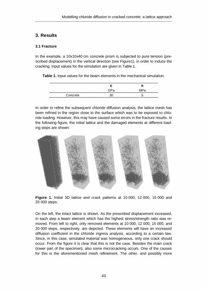
Modelling chloride diffusion in cracked concrete: a lattice approach
43
3. Results
3.1 Fracture
In the example, a 10x10x40 cm concrete prism is subjected to pure tension (pre-scribed displacement) in the vertical direction (see Figure1), in order to induce the cracking. Input values for the simulation are given in Table 1.
Table 1. Input values for the beam elements in the mechanical simulation.
E ft GPa MPa
Concrete 30 5
In order to refine the subsequent chloride diffusion analysis, the lattice mesh has been refined in the region close to the surface which was to be exposed to chlo-ride loading. However, this may have caused some errors in the fracture results. In the following figure, the initial lattice and the damaged elements at different load-ing steps are shown:
Figure 1. Initial 3D lattice and crack patterns at 10 000, 12 000, 15 000 and 20 000 steps.
On the left, the intact lattice is shown. As the prescribed displacement increased, in each step a beam element which has the highest stress/strength ratio was re-moved. From left to right, only removed elements at 10 000, 12 000, 15 000, and 20 000 steps, respectively, are depicted. These elements will have an increased diffusion coefficient in the chloride ingress analysis, according to a certain law. Since, in this case, simulated material was homogeneous, only one crack should occur. From the figure it is clear that this is not the case. Besides the main crack (lower part of the specimen), also some microcracking occurs. One of the causes for this is the aforementioned mesh refinement. The other, and possibly more

Modelling chloride diffusion in cracked concrete: a lattice approach
44
important, cause is that, in the analysis, only the beam cross sectional areas were scaled using the Voronoi scaling, while the shape of the cross-sections was as-sumed to be circular, i.e. no preferential directions for shear and bending are pre-sent. However, in order to achieve a truly homogeneous response, also the inertial moments in both principal directions need to be scaled (Yip et al. 2005), as well as the polar moment of inertia. Further work is needed to refine the present fracture model. Since the emphasis of this work has been the chloride diffusion simulation, no further attempt has been made to achieve realistic mechanical behaviour, and these results were used as input for chloride penetration simulations.
3.2 Chloride diffusion
In the analysis, it is assumed that the diffusion coefficient of a specific lattice ele-ment depends on its damage state: for the uncracked elements and elements with crack widths smaller than 50 μm it is assumed that the diffusion coefficients are equal to those of uncracked concrete (assumed in the analysis to be 6·10-12 m2/s), for elements with crack widths bigger than 200 μm the diffusion coefficient is 106 times higher, while for crack widths between these two values linear interpolation is used. The lower limit is, roughly, consistent with the results of numerous exper-imental studies (Šavija and Schlangen 2010), which state that crack smaller than about 50 μm can self-heal, and in general do not increase the diffusivity. The dif-fusivity adopted for larger cracks is, on the other hand, consistent with the findings of Wang and Ueda (2011), who suggested that the diffusion coefficient of chloride in large cracks is much higher than that in free bulk water, due to additional transport mechanisms which take place inside the crack. These could be, according to them, “convection current due to the small temperature gradient and/or small hydraulic pressure gradient”. The values for diffusion coefficient proposed by Wang and Ueda (2011) were obtained by fitting the numerical results to experi-mental data from the literature, and it could very well be possible that there is no clear physical meaning behind these (high) values, i.e. that these are only applicable for lattice modelling purposes. Therefore, any physical and/or chemical interpreta-tion of the (fitted) values needs to be taken with caution. Still, for this preliminary study, these values were adopted, and will be further examined in future research. The lower and upper boundary crack widths used in this study are taken some-what arbitrarily: different studies suggest values spanning over several orders of magnitude. Therefore, additional experiments are needed to verify these values.
At the exposed surface, a surface chloride concentration of 5·10-3 g/cm3 of con-crete has been prescribed. Chloride penetration depth is defined as the depth at which chloride content equals 12·10-4 g/cm3of concrete, which is approximately the concentration detected by using the silver nitrate spraying. Total simulation time was two years (730 days), with a time step of one day. The results are summa-rized in Table 2 and some of them compared in Figure 2:

Modelling chloride diffusion in cracked concrete: a lattice approach
45
Table 2. Penetration depths at different times and different damage levels (UC-uncracked; EC-number of elements cracked; t-penetration through the whole specimen).
Exposure Maximum penetration depth (mm)
days UC 10 000 EC
10 500 EC
11 000 EC
11 500 EC
12 000 EC
12 500 EC
15 000 EC
20 000 EC
30 6.13 6.13 6.13 6.13 16.37 16.37 19.77 22.5 t
90 9.79 9.79 9.79 9.79 22.61 22.61 22.83 48.79 t
180 14.27 14.27 14.27 14.27 23.16 24.66 28.43 56.33 t
365 20.44 20.44 20.44 20.44 27.38 28.69 32.98 t t
730 29.7 29.7 29.7 31.65 33.69 36.11 46.73 t t
Figure 2. Comparison of penetration depths versus time for different damage levels (EC-number of elements cracked).
In Figure 2 chloride penetration depths are shown only for certain damage levels. In cases of more than 15 000 cracked elements, chloride penetration is very fast, and goes all the way through the specimen, 10 cm in the direction of penetration (in less than 30 days for the case of 20 000 cracked elements). For the cases of 12 500 and 15 000 cracked elements, chloride profiles at different times are de-picted in Figures 3–4 (chloride loading is applied on the left side):
Pene
tratio
n de
pth
(mm
)
Time (days)
Chloride penetration
Uncracked10000 EC11000 EC12000 EC15000 EC

Modelling chloride diffusion in cracked concrete: a lattice approach
46
Figure 3. Chloride penetration profiles for the case of 12 500 cracked elements at 30, 90, 180, 365, and 730 days (from left to right).
Figure 4. Chloride penetration profiles for the case of 15 000 cracked elements at 30, 90, 180, 365, and 730 days (from left to right).

Modelling chloride diffusion in cracked concrete: a lattice approach
47
4. Discussion
The simulation results show that, according to the proposed model, cracking has a marked effect on the chloride penetration. Until a certain threshold is reached, microcracking does not enhance the chloride penetration (see Table 2 and values for 10–12 000 cracked elements). However, when the main (macro) crack starts developing in the specimen, its influence on the chloride penetration depths is obvious. As it gets wider, the penetration becomes faster and faster, which, in a structure, would lead to earlier initiation of the corrosion process, thus greatly reducing the service life. As a matter of fact, this fast penetration could end the service life very fast, if the service life would only include the initiation period. It is also possible to deduce that, for smaller cracks, cracking has a much higher impact in the beginning of the diffusion process, while its impact diminishes with time (see Figure 3). In other words, the penetration front is sharper in the beginning of the process, and becomes flatter with time. The same phenomenon was observed by Marsavina et al. (2009) when simulating the rapid chloride migration in notched specimens. For non-loading induced cracks, which may not penetrate all the way through the concrete cover and reach the reinforcing steel, this could mean the following: the prescribed service life of a structure can be achieved by simply increasing the concrete cover by a certain margin (e.g. as suggested by Yoon et al. 2007). However, when bend-ing cracks do appear, achieving the desired durability becomes more difficult: as shown by Pease (2010), bending cracks propagate all the way to the reinforcement even when the surface crack width is very small. This implies that even for struc-tures which have cracks within limits prescribed by the codes, their service life would be very short. However, in order to properly assess the impact of cracking on the corrosion of reinforcing steel, further research is needed.
5. Conclusions
In the paper, a three-dimensional random lattice model for modelling the chloride penetration in cracked concrete is proposed. A procedure for discretizing the gov-erning equation in space and time has been shown. Using the proposed model, it is now possible to model the three-dimensional chloride diffusion in concrete using an assembly of one-dimensional “pipe” elements. Using a two-step procedure, coupling of the mechanical and transport model has been achieved.
The effect of different cracking levels on the chloride ingress can be assessed. However, in order for the model to be reliable, further experimental and numerical investigations need to be conducted in order to fine-tune the diffusion properties of cracked elements. Also, the model needs to be expanded to include the non-saturated condition- chloride penetration can be governed by transport processes other than pure diffusion. Binding of chloride ions also needs to be included in the model. This should allow quantification of the impact of cracking on the corrosion initiation period, and enable adjusting of accepted service life models in order to take cracking into account.

Modelling chloride diffusion in cracked concrete: a lattice approach
48
6. Acknowledgements
Financial support by the Dutch Technology Foundation (STW) for the project 10978-“Measuring, Modelling, and Monitoring Chloride ingress and Corrosion initiation in Cracked Concrete (M3C4)” is gratefully acknowledged.
References
Bertolini, L., Elsener, B., Pedeferri, P. and Polder, R.B. 2004. Corrosion of steel in concrete: prevention, diagnosis, repair. Weinheim, Wiley-VCH.
Bolander, J.E. and Berton, S. 2004. Simulation of shrinkage induced cracking in ce-ment composite overlays. Cement & Concrete Composites 26, pp. 861–871.
Boulfiza, M., Sakai, K. Banthia, N. and Yoshida, H. 2003. Prediction of chloride ions ingress in uncracked and cracked concrete. ACI Materials Journal 100(1), pp. 38–48.
Costa, A. and Appleton, J. 1999. Chloride penetration into concrete in marine environment- part 1: Main parameters affecting chloride penetration. Ma-terials and Structures 32, pp. 252–259.
Fédération internationale du béton. 2006. Model code for service life design, Inter-national Federation for Structural Concrete (fib), Lausanne.
Grassl, P. 2009. A lattice approach to model flow in cracked concrete. Cement & Concrete Composites 31, pp. 454–460
Marsavina, L., Audenaert, K., De Schutter, G., Faur, N. and Marsavina, D. 2009. Experimental and numerical determination of the chloride penetration in cracked concrete. Construction and Building Materials 23, pp. 1638–1648.
Ožbolt, J., Balabanić, G., Periškić, G. and Kušter, M. 2010. Modelling the effect of damage on transport processes in concrete. Construction and Building Materials 24, pp. 1638–1648.
Pease, B.J. 2010, Influence of concrete cracking on ingress and reinforcement corrosion. PhD thesis, Lyngby, Denmark.
Qian, Z., Schlangen, E., Ye, G., van Breugel, K. 2011. 3D lattice fracture model: theory and computer implementation. Key Engineering Materials 452–453, pp. 69–72.

Modelling chloride diffusion in cracked concrete: a lattice approach
49
Qian, Z. Multiscale modeling of fracture in cementitious materials. PhD thesis, Delft University of Technology, The Netherlands. (In preparation.)
Šavija, B. and Schlangen, E. 2010. Chloride ingress in cracked concrete – a litera-ture review. Advances in Modeling Concrete Service Life, Proc. 4th In-ternational PhD Workshop held in Madrid, Spain, November 19, 2010.
Schlangen, E. 1993. Experimental and numerical analysis of fracture processes in concrete. PhD thesis, Delft University of Technology, The Netherlands.
Schlangen, E. and Qian, Z. 2009. 3D modeling of fracture in cement-based materials. Journal of Multiscale Modelling 1(2), pp. 245–261.
Schlangen, E. and Copuroglu, O. 2010. Modeling of expansion and cracking due to ASR with a 3D lattice model. Fracture mechanics of concrete and con-crete structure, Proc.intern.symp. Seoul, Korea.
Wang, L. and Ueda, T. 2011. Mesoscale modelling of the chloride diffusion in cracks and cracked concrete. Journal of Advanced Concrete Technology 9(3), pp. 241–249.
Yip, M., Mohle, J. and Bolander, J.E. 2005. Automated modeling of three-dimensional structural components using irregular lattices. Computer-Aided Civil and Infrastructure Engineering 20, pp. 393–407.
Yoon, I.S., Schlangen, E., de Rooij, M. and van Breugel, K. 2007. The effect of cracks on chloride penetration into concrete. Key Engineering Materials 348–349, pp. 769–772.

Studies on electrochemical lithium migration for remediation of Alkali-Silica Reaction at macro level in concrete structures
50
Studies on electrochemical lithium migration for remediation of Alkali-Silica Reaction at
macro level in concrete structures
Lourdes M.S. Souza TU Delft, Faculty of Civil Engineering and Geosciences, Delft, The Netherlands
Rob B. Polder
TU Delft, Faculty of Civil Engineering and Geosciences/Materials and Environment, Delft, The Netherlands –
TNO Built Environment and Geosciences/ Civil Infrastructure
ABSTRACT: Alkali-silica reaction (ASR) is a deleterious mechanism known to affect several concrete structures worldwide. During this process, alkali ions pre-sent in the pore solution react with reactive components of the aggregate particle and, as a result a hygroscopic gel is formed. The produced gel absorbs water from the surrounding cement paste and swells. This process might result in expansion and cracking of the concrete. Lithium ions are known to combine with the alkali-silica gel, forming a non-expansive gel. In fresh mixtures, they may be incorpo-rated by the use of lithium based admixtures. However, in existing concrete struc-tures, the ions need to be transported into the cementitious matrix. The ionic mi-gration seems to be more effective than other transport mechanisms, such as diffusion or absorption, reaching higher penetration depths. Nevertheless, little is known on the transport mechanisms involved or on the effects of lithium migration on ASR. In this paper, a review on current literature on lithium migration as a pos-sible ASR mitigation procedure is presented.
1. Introduction
Alkali-silica reaction (ASR) is known as one of the major durability problems in con-crete structures. During the reaction, the reactive siliceous compounds from aggre-gates react with alkalis present in the pore solution, producing a hygroscopic alkali-silica gel. The gel water from surrounding cement paste and swells. The swelling might lead to deleterious expansion and posterior cracking of the concrete.
The most common methods to prevent ASR attempt to limit the availability of one of the three basic components: reactive silica, alkalis and moisture. Using nonreactive aggregate, incorporating supplementary cementitious materials and limiting the equivalent sodium oxide (Na2Oe) content of cement are some of those techniques. As the traditional preventive methods are not always viable, alterna-tives have been suggested, such as the use of lithium compounds as admixtures.
The incorporation of lithium based admixtures has been investigated since the 1950’s. Indeed, McCoy and Cadwell (1951) reported the beneficial effects of the

Studies on electrochemical lithium migration for remediation of Alkali-Silica Reaction at macro level in concrete structures
51
addition of lithium salts in the reduction or prevention of ASR deleterious expan-sion. Since then, several authors (e.g. McCoy and Cadwell 1951, Stark 1992, Hooper et al. 2004) have studied the influence of the addition of varied lithium salts (LiNO3, LiOH·H2O, Li2CO3, amongst others) in concretes and mortars com-posed by different reactive aggregates. It is generally agreed that lithium salts, in the absence of other alkalis, combine with reactive silica in order to produce a gel that does not result in expansion of concretes (Feng et al. 2005). In high alkali content concrete, the minimum lithium to alkali molar ratio necessary to prevent expansion varies between 0.6 and 1.2, for different combinations of reactive ag-gregate, alkali content and lithium compound. If the dosage of lithium is insufficient, a negative effect on the expansive behaviour can be observed. This is probably due to the increase of alkalinity with the addition of the lithium compound, especially LiOH. It is worth noting that different lithium salts do not exhibit the same efficacy in the combat of ASR and LiNO3 appears as the most effective compound (Hooper et al. 2004, Feng et al. 2005, Thomas et al. 2007).The use of lithium based admixtures is a valuable preventive method to be taken into account during the design of con-cretes structures. Nevertheless, regarding the treatment of affected existing concrete structures, the incorporation into the fresh mixture is, obviously, no longer possible. In this case, lithium ions need to be driven into the concrete.
Potential treatment methods of existing structures such as topical applications, vacuum impregnation (Stokes at al. 2002, Thomas et al. 2007) have been investi-gated. However, in those studies, most lithium ions do not penetrate more than about 25 mm (Stoke et al. 2002). Some laboratory investigations compared different methods, such as submitting samples to immersion, vacuum impregnation, wet-dry cycles or electrochemical migration and the latter showed to be the most suitable, providing deeper penetration and higher lithium concentration (Thomas and Stokes 2004, Santos Silva et al. 2008).
This paper brings a review on the investigation of the migration of lithium ions into concrete and its effects on the expansion behaviour of concrete affected by ASR. It also presents some field application of lithium electrochemical treatment on existing concrete structures.
2. Electrochemical lithium ion transport
In an aqueous solution, when an electrical field is applied, the velocity of a given ion is proportional to its characteristics (charge and size) and to the strength of the electrical field. In concrete and mortars, the pores are interconnected and, de-pending of the relative humidity of the environment, they might be partially or completely filled by water. Because of the water-filled pore system, the ion move-ment principles are basically the same as the ones applied in solutions. Positive ions migrate towards the negative electrode (cathode) and the negative ones go in the opposite direction, attracted by the anode. One major difference is that, unlike in bulk solutions, where the ions are able to move through the shortest route, in

Studies on electrochemical lithium migration for remediation of Alkali-Silica Reaction at macro level in concrete structures
52
cementitious materials, they need to pass along narrow and tortuous capillary pores (Bertolini et al. 2004).
Ionic migration in concretes and mortars are applied in treatment techniques, such as cathodic protection (CP), electrochemical realkalization (ER) and electro-chemical chloride extraction (ECE). During these treatments, an electrical field is imposed between the reinforcing steel bar and an external electrode (immersed in an anolyte). Particularly in the case of ER and ECE, a relatively high current (1 to 2 A/m²) is applied and ions are transported towards the anode and cathode. In ECE, chloride ions are forced out of the concrete, attracted by an external anode, whereas in ER, alkali ions are formed at the reinforcement steel. A schematic diagram describing ECE principles is shown in Figure1.
Figure 1. Schematic diagram of the electrochemical chloride extraction set-up.
Driving lithium ions into concrete by means of an electrical field was first suggest-ed by Page (1995), who said that those ions could be introduced in the anolyte during ECE. This way, they would migrate towards the reinforcing steel and miti-gate the effects of ASR on the affected concrete between electrodes. From that idea, the initial investigations came as an adaptation of usual ECE method and some of the further works were done based on the techniques normally used to investigate chloride transport in concrete.
The current studies on the lithium transport and effects on concrete affected by ASR carried out in laboratories can basically be divided in two groups: those which use set-ups similar to those used in rapid chloride migration tests (RCM, NTBuild492 or the comparable ASTM C 1202 – 10), and those that use reinforcement bars as electrodes. Work on the application of the adapted method in existing structures forms a third group. In the following sub-sections, studies of each group will be presented.
2.1. Investigation on “rapid chloride migration test” like set-ups
Some authors have studied the lithium migration through concrete or mortar speci-mens in experimental set ups much similar to the one described in ASTM C 1202-10 – “Standard test method for electrical indication of concrete's ability to resist chlo-ride ion penetration”. In this type of investigation, the sample is placed between two electrolytic cells, as shown in Figure 2. The anodic cell receives the solution

Studies on electrochemical lithium migration for remediation of Alkali-Silica Reaction at macro level in concrete structures
53
with lithium ions, which composition and concentration varied amongst authors. In fact, parameters such as time of test, applied voltage and solution used as catho-lyte and anolyte changed from one work to another. The initial condition of the specimen also varied: in some studies, the samples were previously attacked by ASR, while in others, they were exposed to ARS inducing conditions after the test, and, there was also the case when the reaction was not induced at all. On the other hand, the thickness of the specimen did not exhibit great variation amongst works and it was generally of 50 mm (as it is in the case of the RCM test).
Figure 2. Schematic diagram of “RCM like” set-up.
In a preliminary study of migration of lithium ions, Pacheco and Polder (2010) tested nonreactive mortar samples of water/cement (w/c) ratio of 0.5. They used as anolyte a solution of 1 M LiNO3 and a 0.3 M solution of NaOH as catholyte. The migration mechanism was evaluated in tests with applied voltages of 20 and 40 V, for 28 days. Some samples were also tested at 40 V for 7 days. During the tests, the passing current was recorded and, once they were finished, the lithium content was evaluated in steps of 5 mm by acid dissolution and atomic absorption spec-trometry (AAS). The results showed that the lithium concentration profile after the test depended on the time and applied voltage. Nevertheless, the concentration of lithium decreased towards the downstream side regardless of the conditions of the test. After four weeks of treatment, the content of lithium in the first 10 mm was between 600 and 900 ppm. The maximum concentration was obtained in the test with applied voltage of 40 V during four weeks and it was about 1000 ppm in the first 5 mm. The authors observed an increase of cell resistance during the test, that disappeared over 24 hours after the test. They suggested this might be related to chemical changes in the pore solution due to the migration process.
Thomas and Stokes (2004) submitted reactive concrete specimens to ASR ac-celerating conditions (storage over water at 38°C) until different degrees of expan-sion and cracking, according to Table 1. In the concrete mixture, reactive siliceous limestone as coarse aggregate and high-alkali Portland cement were used. The level of alkali was raised to 1.25% Na2Oe by the addition of NaOH. Once different levels of the reaction were achieved (as specified in Table 1), the specimens re-ceived the electrochemical treatment, in a RCM-like set-up. The catholyte was a

Studies on electrochemical lithium migration for remediation of Alkali-Silica Reaction at macro level in concrete structures
54
solution of 0.3 M KOH with 0.1 NaOH saturated with Ca(OH)2 and the voltage of 20 V was applied until the flow of lithium reached steady state. As the different degrees of cracking implied in more or less paths for the entrance of ions, the time for achieving the steady state flow varied amongst samples between 35 and 101 days. Although it is complicated to compare the results of the treatments for the various times of exposure, it can be concluded that the depth of penetration of lithium ions is proportional to the degree of expansion and cracking. In cracked concrete, greater penetration can be observed even after shorter time of treat-ment. It was noted that, in cracked concrete, depths superior to 30 mm were reached by lithium ions after 35 days. In the first 10 mm, the lithium content varied between 0.10 and 0.15% (or 1000 and 1500 ppm) for all specimens. In fact, the authors pointed out that the lithium to alkali molar ratio necessary to stop the ex-pansion (i.e. [Li]/[Na+K] = 0.74) was achieved in depths superior to 30 mm.
Table 1. Expansion and cracking of tested specimens over time (Thomas and Stokes 2004).
Time (days) Expansion (%) Cracking 28 0.018 No visible cracking
70 0.061 Hairline cracks
112 0.107 Significant map cracking (crack width up to 1 mm)
Lee et al. (2008) investigated the influence of the thickness of the specimens on lithium ion migration. For that, concrete specimens thicknesses varying from 50 to 200 mm were tested at the age of 28 days. In the concrete mixture, reactive sand-stone was used as aggregate, the Na2Oe was adjusted to 1.25% by addition of NaOH and the w/c was 0.6.
The specimens were tested under constant current density of 9 A/m² during 30 days. A solution 1 N of LiOH·H2O and a saturated solution of Ca(OH)2 were used as electrolytes. During the test, sodium content of the cathodic cell solution was measured and the results showed the sodium ions were removed from the speci-mens. Regarding the movement of lithium ions, the authors concluded that the time for the ions to pass through the sample is directly proportional to its thick-ness. Nevertheless, the average Li/Na molar ratios of all samples, regardless the size, were higher than 2.0, above the known mitigation values. However, most lithium ions were concentrated in the first 25–30 mm from the exposed surface.
It is noteworthy that CaCO3 crystals blocking the pores were found in all speci-mens, leading to the increase of resistivity of the samples during the test. In order to evaluate the effect of the treatment on the expansive behaviour, treated speci-mens were submitted to ASR accelerating conditions (38°C and 100% R.H.) for one year and the results, shown in Table 2, indicate reduction of the expansion.

Studies on electrochemical lithium migration for remediation of Alkali-Silica Reaction at macro level in concrete structures
55
Table 2. Expansion behaviour after one year curing at 38°C and 100% R.H. (Lee et al. 2008).
Expansion (%) Specimen’s height (cm) Control Treated
5 0.289 -0.252
10 - -0.090
15 - 0.004
20 0.836 0.008
Instead of evaluating the treatment of cast specimens, Santos Silva et al. (2008) tested cores from railway concrete sleepers which were cracked by ASR and delayed ettringite formation. The cores with length of 50 mm and diameter of 74 mm were treated for a week and voltages of 20, 40 and 60 V were evaluated. In this study, the electrolytes were water and a solution 30% of LiNO3. Like in other studies, the authors observed the influence of the applied voltage on the efficacy of the ionic transport. The alkali removal from the cores was also noted. The effect of the electrochemical treatment on the expansion behaviour was evaluated on cores treated at 60 V and then placed in a fog chamber at 20ºC and 95% R.H for 180 days. The results indicated that the electrochemical treatment had better effect on the expansion than the application of coatings. However, untreated samples were not evaluated, making it difficult to analyse the efficacy of the treatments.
The behaviour of the sodium, potassium and lithium ions in mortar under an electrical field was investigated by Liu et al. (2011) in a RCM like set-up, where the electrolytes were a solution 1 N of LiOH·H2O and a saturated solution of Ca(OH)2. The concrete was produced with reactive meta sandstone, w/c of 0.5 and the total Na2Oeq was 11.37 kg/m³. The specimens were cured for 3 months at 23ºC and 100% R.H. before being tested. Five different voltages were used, 12, 18, 24, 30 and 40 V, and the tests stopped once the flow of lithium had reached steady state (approximately 33 days for the test at 40 V and 50 for the rest).
The authors observed that the removal time of sodium and potassium ions de-pended on the applied voltage. It was also noted that the time for lithium ions to go through the sample decreased when the applied voltage increased. Nevertheless, only about 10% of the applied charge was used to remove the alkalis and 1.4–3.6% of the applied charge was used to impregnate the sample with lithium ions. Finally, the alkali contents of the samples at the end of the test were less than 0.6 kg/m3 and the average Li/(Na+K) molar ratios were above 9. Once again, it must be noted that most ions were concentrated at the first 30 mm from the ex-posed surface.
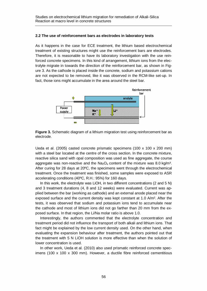
Studies on electrochemical lithium migration for remediation of Alkali-Silica Reaction at macro level in concrete structures
56
2.2 The use of reinforcement bars as electrodes in laboratory tests
As it happens in the case for ECE treatment, the lithium based electrochemical treatment of existing structures might use the reinforcement bars are electrodes. Therefore, it is reasonable to have its laboratory investigation with the use rein-forced concrete specimens. In this kind of arrangement, lithium ions from the elec-trolyte migrate in towards the direction of the reinforcement bar, as shown in Fig-ure 3. As the cathode is placed inside the concrete, sodium and potassium cations are not expected to be removed, like it was observed in the RCM-like set-up. In fact, those ions might accumulate in the area around the steel bar.
Figure 3. Schematic diagram of a lithium migration test using reinforcement bar as electrode.
Ueda et al. (2005) casted concrete prismatic specimens (100 x 100 x 200 mm) with a steel bar located at the centre of the cross section. In the concrete mixture, reactive silica sand with opal composition was used as fine aggregate, the course aggregate was non-reactive and the Na2Oe content of the mixture was 8.0 kg/m³. After curing for 28 days at 20ºC, the specimens went through the electrochemical treatment. Once the treatment was finished, some samples were exposed to ASR accelerating conditions (40ºC, R.H.: 95%) for 160 days.
In this work, the electrolyte was LiOH, in two different concentrations (2 and 5 N) and 3 treatment durations (4, 8 and 12 weeks) were evaluated. Current was ap-plied between the bar (working as cathode) and an external anode placed near the exposed surface and the current density was kept constant at 1.0 A/m². After the tests, it was observed that sodium and potassium ions tend to accumulate near the cathode and most of lithium ions did not go farther than 20 mm from the ex-posed surface. In that region, the Li/Na molar ratio is above 1.0.
Interestingly, the authors commented that the electrolyte concentration and treatment period did not influence the transport of both alkali and lithium ions. That fact might be explained by the low current density used. On the other hand, when evaluating the expansion behaviour after treatment, the authors pointed out that the treatment with 5 N LiOH solution is more effective than when the solution of lower concentration is used.
In other work, Ueda et al. (2010) also used prismatic reinforced concrete spec-imens (100 x 100 x 300 mm). However, a ductile fibre reinforced cementitious

Studies on electrochemical lithium migration for remediation of Alkali-Silica Reaction at macro level in concrete structures
57
composite (DFRCC) layer containing lithium with an embedded steel mesh was the anode. In the concrete mixture, reactive course aggregate and non-reactive fine aggregates were used, in the ratio of 7:3 and the Na2Oe content of the con-crete was 8.0 kg/m³.
Two different lithium salts (LiOH and LiNO3) were investigated as admixtures in the DFRCC layer,. After 28 days of curing at 20ºC, the reinforced beams were immersed in the electrolyte (0.1 mol/l Li3BO3) and the electric current between the anodic layer and the reinforcement bar was supplied. Two different current densi-ties were applied: 0.05 A/m² during 16 weeks and 1.0 A/m² for 8 weeks. After the tests, alkali concentration near the cathode was observed and the lithium ions mainly concentrated near the exposed surface, in the first 20 mm of the concrete beam, regardless of the intensity of the current. Anyhow, it was highlighted that the lithium permeation was not as effective as expected.
A different reinforcement arrangement was used in the work of Bentivegna et al. (2011). Large-scale reinforced cylindrical concrete columns (0.61 m of diameter and 1.22 m of height) were cast with reactive aggregate and “sufficient alkali” in order to be expansive and result in cracking. After achieving the expansion of 0.1%, two specimens were submitted to the treatment, using the reinforcement bars as electrodes and LiNO3 solution as electrolyte, during five weeks. As result of the test, in the first 40 mm from the exposed surface, the levels of lithium ions would be enough to supress the reaction and most of the ions concentrated on the first 20 mm. It is important to comment that the authors considered 100 ppm as the necessary concentration of lithium ions to mitigate ASR. The expansion was monitored for over 1000 days and the treated and untreated specimens exhibited similar behaviour.
2.3 The treatment of existing structures
As mentioned before, the first attempts of application of the electrochemical lithium treatment in existing structures suffering effects were derived from modifications of ECE procedure. In these structures, where ECE treatment was already needed, ASR was also observed; therefore, the combination of both techniques was interesting.
Whitmore and Abbot (2000) described the application of the electrochemical lithium treatment in conjunction with the ECE in two bridge decks located in the USA. The ECE procedure was modified by the substitution of the usual electrolyte (water) for lithium borate solution and the treatment lasted 8 weeks. The rein-forcement steel bars were used as cathodes, but the authors pointed out the pos-sibility of using extra cathodes in structures with little reinforcement. The results showed that lithium migration was achieved in a relatively short time of treatment. However, neither the maximum depth of penetration nor the effects of the treat-ment were evaluated.
In the work of Bentivegna et al. (2011), the mitigation of ASR was the primary goal, in contrast with other cases. They reported the 5-week treatment of bridge columns affected by ASR with the use of LiNO3 as electrolyte. In order to obtain migration not only on the surface, holes were drilled to a depth of several centime-

Studies on electrochemical lithium migration for remediation of Alkali-Silica Reaction at macro level in concrete structures
58
tres behind the rebar. Into them, extra anodes and irrigation tubes were inserted to provide impregnation from inside the rebar cage. The arranged set-up is shown in Figure 4. The final effects were evaluated by the monitoring of both expansion and propagation of the cracking. According the authors, the treatment did not reduce the expansion or cracking. In fact, cracks were noted in treated columns after five years. It was also emphasized that the electrochemical procedure is a time-consuming and high-cost mitigation method.
Figure 4. The field application of the electrochemical lithium treatment in a bridge in USA (Bentivegna et al. 2011).
3. Concluding remarks
From the review above, it can be seen that some principles of lithium migration and its effect on concrete affected by ASR are still not fully understood. The variability amongst the experimental procedures adopted by the several mentioned authors makes it difficult to compare the results. A question should be raised about the differences between the types of tests and their influence on the final results. For example, in investigations using RCM like set-ups, alkali ions are removed, result-ing in a situation that might be better than when rebars are used as electrodes. The accumulation of alkali ions in the region around the rebar should not be ne-glected, as it might lead to a worse situation in that area with regard to ASR.
Regarding the parameters that control the migration of lithium ions, it is gener-ally agreed that the applied voltage and time of the test influence the rate of pene-tration and the final concentration profile. In Table 3, it is worth noting that, in some lithium migration studies, significantly higher current density have been used than it is common in ECE and ER of concrete (Bertolini at al. 2004). In fact, when the current density value is comparable to that applied during ECE or ER, lithium
Studies on electrochemical lithium migration for remediation of Alkali-Silica Reaction at macro level in concrete structures
59
impregnation is not expressive (e.g. Ueda et al. 2005, 2010). This might be ex-plained by the relatively poor efficiency of the migration of lithium ions pointed out by Liu et al. (2011).
Nevertheless, the present studies have not been able to enhance the maximum penetration depth, leaving areas beyond the first 30–40 mm relatively untreated. It seems interesting to study possibilities of either anodes (with lithium) or cathodes placed inside the concrete. Also, the influence of other parameters such as the type and concentration of lithium solution used and lithium binding are still not clear.
Table 3. Applied or measured current densities of reviewed studies.
Studies where constant voltage was applied
Studies where constant current density was applied
Research work
Voltage (V)
Current density (A/m²)
Research work
Current density (A/m²)
Pacheco and Polder (2010)
40 (1 week)
15.0–13.0 Ueda et al. (2005)
1.0
20 (4 weeks)
4.0–5.0 Ueda et al. (2005)
0.05
40 (4 weeks)
7.0 Ueda et al. (2010)
1.0
Liu et al. (2011)
12 3.9
18 5.7
24 7.1
30 9.4
40 21.8
It is interesting to notice that, in the reviewed papers, little or nothing has been said about the pore structure of the material. As before mentioned, the ionic transport through concrete or mortars depends on the tortuosity of the path and comparing results without the characterization of the pore structure can lead to unreliable conclusions. A similar remark can be made concerning the pore solution composition.
Another important aspect is the Li/Na2Oe molar ratio that should be reached in order to mitigate ASR. The current works have been comparing the ratios obtained during the electrochemical treatment of hardened concrete with values from the literature for preventing the reaction on new concrete. The literature values were obtained from the case when the lithium salt is incorporated to the fresh mixture and the mechanism of action of lithium ions on ASR in hardened concrete might be different.
Further work on elucidating the parameters that control lithium ion transport and the mechanisms by which the ions retard ASR in hardened concrete is still needed. A treatment procedure can only be developed once these questions can be answered.

Studies on electrochemical lithium migration for remediation of Alkali-Silica Reaction at macro level in concrete structures
60
4. Acknowledgements
The authors are grateful to the Dutch Technology Foundation (STW) for the finan-cial support for the project 10971: “Modelling, non-destructive testing and Li-based remediation of deleterious Alkali-Silica Reaction in concrete structures”.
References
Bentivegna, A.F., Giannini, E.R. and Folliard, K.J. 2011. Use of electrochemical migration to mitigate alkali-silica reaction in large scale concrete struc-tures. In: Concrete Solutions; Proc. 4th intern. conf. of Concrete Repair, Dresden, Germany, September 2011.
Bertolini, L., Elsener, B., Pedeferri, P. and Polder, R.P. 2004. Corrosion of steel in concrete. Weinheim: Wiley.
Feng, X., Thomas, M.D.A., Bremner, T.W., Balcom, B.J. and Folliard, K.J. 2005. Studies on lithium salts to mitigate ASR-induced expansion in new concrete: a critical review. Cement and Concrete Research 35(9), pp. 1789–1796.
Hooper, R.L., Nixon, P.J., Thomas, M.D.A. 2004. Considerations when specifying Lithium admixtures to mitigate the risk of ASR. In: T. Mingshu and D. Min, Peking (Eds.). 12th International Conference on Alkali-Aggregate Reaction in Concrete, Proceedings, Beijing, October 2004. Beijing: Bei-jing World Publishing Corporation. Pp. 554–563.
Lee, C., Liu, C.C. and Wang, W.C. 2008. Effect of the distance between elec-trodes on the performance of using electrochemical technique to repair the concrete damaged by AAR. In: M. Broekmans and B.J. Wigum (Eds.). 13th International Conference on Alkali-Aggregate Reaction in Concrete (ICAAR), Proceedings, Trondheim, June 2008.
Liu, C.-C., Wang, W.-C. and Lee, C. 2011. Behavior of cations in mortar under accelerated lithium migration technique controlled by a constant voltage. Journal of Marine Science and Technology 19(1), pp. 26–34.
Marcotte, T.D., Hansson, C.M. and Hope, B.B. 1999. The effect of the electro-chemical chloride extraction treatment on steel – reinforced mortar. Part I: Electrochemical measurements. Cement and Concrete Research 29(10), pp. 1561–1568.
McCoy, E.J. and Caldwell, A.G. 1951. New approach to inhibiting alkali-aggregate expansion. Journal of the American Concrete Institute 22, pp. 693–706.

Studies on electrochemical lithium migration for remediation of Alkali-Silica Reaction at macro level in concrete structures
61
Pacheco Farias, J. and Polder, R.B. 2010. Preliminary study of electrochemical lithium migration into cementitious mortar. In: K. van Breugel, G. Ye and Y. Yuan (Eds.). 2nd International symposium on service life design for in-frastructure, Proceedings, Delft, October 2010, Bagneux, France: RILEM publications. Pp. 1093–1100.
Page, C.L. and Yu, S.W. 1995. Potential effects of electrochemical desalination of concrete on alkali-silica reaction. Magazine of Concrete Research 47(170), pp. 23–31.
Santos Silva, A., Salta, M., Melo Jorge, M.E., Rodrigues, M.P. and Cristino, A.F. 2008. Research on the suppression expansion due to ASR. Effect of coatings and lithium nitrate In: M. Broekmans and B.J. Wigum (Eds.). 13th International Conference on Alkali-Aggregate Reaction in Concrete (ICAAR), Proceedings, Trondheim, June 2008.
Stark, D.C. 1992. Lithium salt admixtures – an alternative method to prevent ex-pansive alkali – silica reactivity In: Proceedings of the 9th International Conference on Alkali–Aggregate Reaction, Concrete Society of U.K, London. P. 1017.
Stokes, D.B., Pappas, J., Thomas, M.D.A. and Folliard, K.J. 2002. Field cases involving treatment or repair of ASR-affected concrete using lithium. In: V.M. Malhotra (Ed.). Sixth CANMET/ACI International Conference on Du-rability of Concrete, Proceedings, Greece, Supplementary Papers, Farm-ington Hills: American Concrete Institute. Pp. 631–642.
Thomas, M.D.A. and Stokes, D.B. 2004. Lithium impregnation of ASR-affected concrete: preliminary studies. In: T. Mingshu and D. Min, Peking (Eds.). 12th International Conference on Alkali-Aggregate Reaction in Concrete, Proceedings, Beijing, October 2004, Beijing: Beijing World Publishing Corporation. Pp. 659–667.
Thomas, M.D.A., Fournier, B., Folliard, K.J., Ideker, J.H. and Resendez Y. 2007. The use of lithium to prevent or mitigate alkali-silica reaction in concrete pavements and structures. Report from Federal Highway Administration FHWA-HRT-06-133, Washington D.C: U.S. Department of Transportation.
Ueda, T., Yoshida, Y., Yamaguchi, K. and Ashida, M. 2005. Effect of electrochem-ical penetration of lithium ions on ASR expansion of concrete. In: Third International Conference on Construction Materials, Proceedings, Van-couver, August 2005.

Studies on electrochemical lithium migration for remediation of Alkali-Silica Reaction at macro level in concrete structures
62
Ueda, T., Kameda, T., Maeda, T. and Nanasawa, A. 2010. Suppression of ASR expansion due to electrochemical penetration of lithium supplied by DFRCC anode system. In: Sixth International Conference on Concrete under Severe Conditions, Proceedings, Merida, June 2010. Pp. 1229–1236.
Whitmore, D. and Abbot, S. 2000. Use of an applied electric field to drive lithium ions into alkali-silica reactive structures. In: M.A. Bérubé, B. Fournier and B. Durand (Eds.). 11th International Conference on Alkali-Aggregate Re-action in Concrete (ICAAR), Proceedings, Quebec City, June 2000. Pp. 1089–1098.

Effects of climate change on deterioration of structures and repair need of existing building stock in Finland
63
Effects of climate change on deterioration of structures and repair need of existing
building stock in Finland
T. Pakkala, J. Lahdensivu, M. Pentti Tampere University of Technology, Department of Civil Engineering, Finland
ABSTRACT: An enormous share of Finland’s national property consists of the existing building stock which makes this study significant from an economic point of view. The maintenance and protection of the existing building stock are highly important for the welfare of the nation. In Finland its significance is emphasized due to buildings’ exposure to severe weather conditions.
A soon beginning research project concentrates on studying the effects of cli-mate change on the existing building stock in Finland. At first, the project explores different climate change scenarios and then, based on earlier studies, determines how the different scenarios may affect deterioration of structures and the repair need of existing buildings. As a result this project should be able to produce esti-mations of the accumulated amount of deterioration and the rate of different dete-rioration mechanisms and processes of existing apartment blocks in Finland in 2030 and 2050 based on different climate change scenarios and probabilities of each scenario.
1. Background and significance
This research project concentrates on researching effects of climate change to existing building stock in Finland. At first the project gets acquainted on different climate change scenarios and then, based on earlier studies, studies how the different scenarios may effect on deterioration of structures and repair need of existing buildings. As a result it should also give ideas for new structural solutions.
An enormous share of Finnish national property consists of the existing building stock which makes this study significant from an economic point of view. Thus maintenance and protection actions of the existing building stock are remarkably important for welfare of the nation. In Finland their significance is emphasized because of severe outdoor exposure to weather conditions. Detached houses are delimited out of the research because they are structurally highly heterogeneous and they are built in different periods of time. Otherwise Finnish building stock is relative young and homogenous compared to the rest of Europe. As a conse-quence of urbanization, starting in 1960s, a considerable amount of buildings has come near to the end of their technical service life i.e. caused, to a great extent, by weathering. Thus, it is important to explore the possible scenarios of the climate change.

Effects of climate change on deterioration of structures and repair need of existing building stock in Finland
64
1.1 Finnish building stock
Over 70% of Finnish national property is attached to built environment and 47% in the building stock only. The estimated value of the building stock is 360 billion €. The building stock consists of 2.4 million buildings which include over 1.2 million residential buildings. Most of the residential buildings are detached houses in which almost half of the Finnish population live. Apartment houses are concentrated in big cities and they cover only 4.5% of the total amount of the residential buildings however 34% of the population of Finland live in these housings. (ROTI 2011)
Wood covers 35% and brickwork 27% of all façade areas in Finnish building stock. That is mostly because wood is still a main material for facades of detached houses and brickwork has been one of the main façade materials in both detached houses and apartment houses over the decades. Uncoated or coated (e.g. with brick tiles or ceramic tiles) precast concrete walls cover 11% of all facades and rendering 7% of all facades. (Vainio et al. 2005)
The value of house building was 20.5 billion € in 2010. New building amounted to 10.9 billion € whereas renovation amounted to 9.6 billion € (ROTI 2011). In 2008 residential building part was 4.9 billion € (Rakennuslehti 2011, referenced: VTT/RT, Tilastokeskus). The volume of the renovation is increasing because the Finnish building stock is homogenous and fairly new compared to e.g. South and Middle Europe. Most of the stock is built after the 1960s. For example construction with precast concrete panels increased at that time because of the urbanization and most of it is built during the 1960s and 1970s. Buildings constructed at that time are coming at the end of their service life and they need to be renovated. In 2000 costs of renovating precast concrete facades was 125 million € (Vainio et al. 2002). Although the share of precast concrete panels and other concrete facades is only 18% of all the facades its renovation volume is and will be significant within near future. (Lahdensivu 2010)
1.2 Finnish climate and its effect on buildings in Finland
Climate exposure such as outdoor temperature, relative humidity and amount of rain vary annually considerably but average changes are minor. Based on the data of the Finnish Meteorological Institute the annual average temperature has risen slightly after the 1970s. However, there has been a need for repair of the buildings as a consequence of ageing caused by exposure to the climate. The weathering has caused quality weakening, also known as deterioration, of building materials such as frost damage, corrosion of reinforcement and damage caused by micro-organisms. (Lahdensivu 2010)
Climate has a great affect on deterioration and thermal and humidity function of structural elements. Normally climate change is considered as a global warming caused by increased greenhouse gases, e.g. carbon dioxide. The climate change is also considered to have effect on rain, wind conditions, cloudiness, air humidity and solar radiation. (Jylhä 2009)

Effects of climate change on deterioration of structures and repair need of existing building stock in Finland
65
Globally, there are several different climate models for estimating forecasts of the climate change. The climate models are based on future scenarios of green-house gas emissions in which different assumptions about future development of e.g. growth of population, economics and energy production modes are estimated. (Jylhä 2009)
In an ACCLIM project the Finnish Meteorological Institute has examined the dif-ferent climate models, estimated models for Finnish climate conditions and adapta-tion to climate change. In all gas emission scenarios the average temperature raises equivalently and equally fast until the year 2040. The biggest differences between scenarios are predicted to occur after the middle of the century. (Jylhä 2009)
Nowadays calculated life cycle in building design is typically 50–100 years and service life of older building stock is tried to be lengthened by renovation. Thus there is major need for functionality studies on repaired structures and repair methods taking into account future climate. These studies are a major part of a FRAME project which is at the present moment in progress at Tampere University of Technology. The project is based on data of the ACCLIM project (Jylhä 2009). However, the ACCLIM project is based on only one future scenario of greenhouse gas emissions.
The ACCLIM and FRAME projects have shown that in the future climate condi-tions are likely to become worse considering durability of facades and structures. It is shown with precast concrete buildings that the present deterioration of facades and balconies is faster in the coastal areas and southern Finland than inland, eastern and northern Finland (Köliö & Lahdensivu 2011). According to the data of the ACCLIM project again, precipitation during winter season is going to increase while the form of raining is going to change to more water and wet snow. At the same time circumstances for drying are going to get worse. Thus, the failure rate of the structures will increase in most of Finland if maintenance and protection actions are neglected. (Lahdensivu 2010)
Rendering of the facades almost stopped in the beginning of the 1960s when rendered brickwork gave way for buildings made of precast concrete panels. However, tightened insulation regulations in Finland within the last decade have lead to an increasing use of rendering with external thermal insulation systems (ETICS). It is a commonly used method especially with renovation of precast con-crete element buildings because it gives a possibility to easily improve the heat insulation capacity of the external walls. However, there have been many prob-lems especially with frost damage of the backing coat. Thus both ETICS and con-crete element buildings have their own research problems with changing climate. (Pakkala & Suonketo 2011)
2. Research questions
The goal of this research project is to determine proper actions on the building site for adaptation to the climate change. It should cover both the adaptation of exist-ing buildings and new structural solutions. It requires understanding of the climate change itself and the models based on different greenhouse gas emission

Effects of climate change on deterioration of structures and repair need of existing building stock in Finland
66
amounts. Also it requires becoming acquainted with the BeKo-database which consists of information and measured data of condition investigation reports of about 950 existing Finnish concrete buildings (Lahdensivu et al. 2010).
The following questions are to be addressed in the research:
1. How do different greenhouse gas emission scenarios affect climate change and which are the probabilities of occurrence of each scenario?
2. How do the different climate change scenarios affect rain intensity, windiness, wind direction and freeze-thaw cycles?
3. How do the scenarios change the difference between coastal areas and in-land?
4. How does the existing building stock adapt to climate change?
5. How does the climate change have an effect on occurrence of and deterio-ration by micro-organisms?
6. What will be the requirements for new structural solutions when climate change is taken into account?
3. Research design and methods
3.1 Research material
The Finnish Meteorological Institute (FMI) has weather data since 1961 in digital form from several meteorological stations which cover whole Finland. The data consists of temperature, relative humidity, rain intensity, wind speed and direction, solar ration variables etc. These observations have been collected at least daily and three times a day at best. In the REFI-B project the FMI has also made an estimation of prevailing climates on four localities (Vantaa, Jokioinen, Jyväskylä, Sodankylä) for three time periods (until 2030, 2050 and 2100). The estimation is based on the average of 19 different models which are all based on greenhouse gas emission scenario A2. The A2 scenario is based on a situation where green-house gases are assumed to increase heavily, thus it is considered to be a sort of worst-case estimation. The FMI has also information of the other significant greenhouse gas emission scenarios which are A1B (quite large emissions) and B1 (small emissions). (Jylhä et al. 2011).
A comprehensive database of 947 façade condition assessment reports has been assembled during a previous research project “BeKo – Repair Strategies of Concrete Facades and Balconies” in 2006–2009 by the Department of Civil Engi-neering of Tampere University of Technology (TUT). This unique data consists of degradation related material properties of the structures including e.g. porosity, tensile strength and carbonation depth of the concrete and the cover depth meas-urements of reinforcement as well as the observed degradation by visual inspec-

Effects of climate change on deterioration of structures and repair need of existing building stock in Finland
67
tion and through thin section analysis made in the laboratory. The buildings in the database are built during 1961–1996. (Lahdensivu et al. 2011)
Micro-organisms have not been a considerable problem for facades in Finland because the climate is not optimal for microbial growth. Therefore there have not been extensive studies on microbial growth. In 1999 “Microbiological Functionality of Precast Concrete Panels” was published where the microbial growth inside precast concrete exterior walls of 26 multi-storey buildings in southern Finland were studied. The buildings represented different ages and surfaces finishes in concrete. The study was made by analyzing mesophilic bacteria and fungal spores with the cultivation method and the total amount of samples was 1713. (Pessi et al. 1999) What was the conclusion of this study on microbiologial degradation?
3.2 Research methods
The research work will be performed using statistical examination and calculus of probability of the material described above, literature research and comparison to experimental measurements of degradation using accelerated weathering tests. The BeKo–database on the material properties and degradation of concrete fa-cades and weather data provided by the FMI is available for these tasks.
The aim with literature research is to understand meteorological phenomena and different degradation models. It should give comprehension to process the related data. The statistical examinations and calculus of probability are needed because estimations of prevailing climate made by the FMI in REFI-B project have two major downsides: there is no estimation for the factor of uncertainty and no consideration how restrictions of greenhouse gases will affect the estimations. However, both of the downsides can be solved by studying all the different mod-els. This study has to be done with certain restrictions, e.g. all models cover tem-perature quantities but only 10 cover wind quantities and 7 humidity quantities. The A1B and B1 models are supposed to be used in the research to compare the results of A2-model to more conservative estimations. The examinations and calculations are made in co-ordination with the FMI.
The BeKo-database is used to gather information of present degradation and to consider how the degradation modes will respond to changing climate. The BeKo-database with climate data by the FMI has given information about e.g. the rela-tion between annual rainfall and corrosion rate of reinforcement in existing con-crete facades. In addition it has given information that in coastal areas more frost weathering occurs because the amount of rain is higher and the wind speed is higher, despite the fact that more freeze-thaw cycles occur inland than in coastal areas. (Lahdensivu 2010). Thus the BeKo-database has given significant infor-mation about the reason for failures in the present climate and that can be used for estimating the degradation in the future climate when the amounts of quantities which represent climate conditions (e.g. temperature, rain intensity, wind speed etc.) are within at present known limits.
Although in Finland extensive problems with damages on facades caused by micro-organisms have not occurred, recent observations have indicated that in

Effects of climate change on deterioration of structures and repair need of existing building stock in Finland
68
future degradation by micro-organisms is likely to happen more often. It is sup-posed to be a consequence of milder winters and more rainy autumns but there have no researches been made on this subject after 1999. At that time only 6.6% of all the samples were distinctly contaminated. In this research the damages caused by microbes are not the main focus but a possible tendency of climate exposure to microbe growth because of climate change will be determined.
The accelerated weathering tests will be used for researching the effect of changing climate conditions which are heavier or more intensive than at present, e.g. amount of rain, rain intensity and wind speed are estimated to be much higher than at present. The accelerated weathering tests will be used also for testing new structural solutions. A relevant testing machine already exists at the Structural Laboratory of the Department of Civil Engineering at TUT. In addition, required new testing machines and methods can be made in the above-mentioned labora-tory with experienced researchers.
3.3 The facilities for research
Work for this research project will be carried out in the Department of Civil Engi-neering of Tampere University of Technology (TUT). The degradation of concrete structures and the behaviour of different construction materials in laboratory as well as in field exposure have been studied at the TUT Department of Civil Engi-neering since the 1980s. Condition assessment systematics and various repair methods for concrete facades, nowadays common in every repair project in Fin-land, have been developed at TUT. Renovation of structures is one of the most active research domains of the Department of Civil Engineering.
This project utilizes the results of recent research projects conducted at TUT Department of Civil Engineering (Lahdensivu et al. 2010). The expertise of a group of ten researchers and research assistants, currently working on service life engi-neering of structures, is available to contribute to the work of the PhD student. The leader of the research group, research manager Jukka Lahdensivu, will act as an instructor for the research work. Professor Matti Pentti will act as the supervisor of the research project and for the doctoral dissertation work. The research work will be done by PhD student Toni Pakkala.
This project is carried out in parallel and in cooperation with another PhD pro-ject which is starting at the same time. The two projects supplement each other while the first project concentrates on the different climate scenarios and their impact on the existing building stock the other concentrates on developing a new methodology for the estimation of service life concentrating on the existing building stock and the actual impact of outdoor climate.
Cooperation regarding this research project will be arranged with the Finnish Meteorological Institute (FMI). The liaisons with the institutes are Reija Ruuhela, climatic conditions, FMI, Kirsti Jylhä, the impact of climate change, FMI and Kimmo Ruosteenoja, estimation of climate models, FMI.
The researchers of the Department of Civil Engineering at TUT have estab-lished extensive personal contacts with the leading researchers in the field of

Effects of climate change on deterioration of structures and repair need of existing building stock in Finland
69
expertise in Europe and in the United States during previous international and national research projects. Thus, the researcher exchange possibilities are highly achievable.
4. Expected results and dissemination
This project is meant to produce estimations of deterioration levels and methods of at present existing apartment houses in Finland at 2030, 2050 and 2100 based on different climate change scenarios. The estimations are highly important base for considering upcoming renovations and also new structural solutions.
A major part of Finnish national property is in existing building stock and a sig-nificant portion of it is in critical stage of their service life based on the present propagation state of degradation. It is a consequence of a measure of precast concrete panel buildings which were built in the largest cities because of the ur-banization since the 1960s. The repair need of prefabricated concrete facades built in 1965–1995 in Finland has been estimated to 3.5 billion € (Köliö 2011). Thus, the correct renovation methods are extremely important for lengthening of the service lives of such valuable national property. This research should provide the methods and actions which should be made to assure the extended service life.
The estimations of deterioration levels and methods will be based on a unique BeKo-database where different deterioration levels and methods of about 950 buildings are collected. However, changing climate exposures may produce new kinds of deterioration methods and that will be determined by different accelerated weathering tests. For example rain intensity is going to rise and with accelerated weathering with relevant testing machine already available at the Structural La-boratory of the Department of Civil Engineering at TUT tests can be made. The result should assist the construction industry to produce durable solutions for structural materials.
5. Timetable and financial plan
The research project will start January 1st 2012 with a comprehensive study of the current state of the art of commonly used climate change scenarios based on different greenhouse gas emission scenarios and well-known deterioration meth-ods of structures. The first results of the literary study are expected to be ready in mid 2012. The adaptation of the building stock to the climate change will start after the literature study. The experimental period is scheduled from the beginning of 2013 until the end of 2014 including accelerated weathering tests for known and upcoming structures. The schedule is yet fairly open because the tests depend partially on the previously done studies in the project. The results related to the tests will be presented during the year 2014. The last year of the project will be used to validate and disseminate the results obtained and for the completion of the doctoral dissertation. Researcher exchange will be arranged depending on a funding,

Effects of climate change on deterioration of structures and repair need of existing building stock in Finland
70
the project timetable and the situation in life of the PhD student. The project will end December 31st 2015.
The expenses of this project are composed of salary, travel expenses, out-sourcing service (gathering of weather data and calculus of probability, FMI) and laboratory tests. The funding applications are sent to RYM-TO scholarship and to the Academy of Finland which hopefully could cover most of the expenses. The rest of the expenses are supposed to be funded by real estate companies and internally by the Department of Civil Engineering of TUT.
References
Jylhä, K., Ruosteenoja, K., Räisänen, J., Venäläinen, A., Tuomenvirta, H., Ruoko-lainen, L., Saku, S. and Seitola, T. 2009. The changing climate in Finland: estimates for adaption studies. ACCLIM project report 2009. Finnish Meteo-rological Institute. Reports 2009:4. Helsinki. 78 p. + app. 36 p. (In Finnish)
Jylhä, K. et al. 2011. Rakennusfysiikan ilmastollisten testivuosien sääaineistot nykyisessä ilmastossa ja arviot tulevaisuuden muutoksista. Väliraportti. Finnish Meteorological Institute. Helsinki. 6 p. + app. 20 p. (In Finnish.)
Köliö, A. and Lahdensivu, J. 2011. Calculation example for anticipating the repair need of concrete façade and balcony structures. Proceedings of XII In-ternational Conference on Durability of Building Materials and Compo-nents, Vol. 3. Porto, Portugal 12.–15.4.2011. Pp. 1275–1282.
Köliö, A. 2011. Betonilähiöiden julkisivujen tekninen korjaustarve (Degradation induced repair need of concrete facades). Tampere University of Tech-nology. Department of Civil Engineering. Tampere. MSc thesis. 74 p. + app. 36 p.
Lahdensivu, J., Varjonen, S. and Köliö, A. 2010. Repair strategies of concrete facades and balconies. Tampere University of Technology. Structural Engineering. Research report 148. Tampere. 79 p.
Lahdensivu, J. 2010. The Durability of facades and balconies in a changing climate. Ministry of the Environment. Department of the Built Environment. The Finnish Environment 17/2010. Helsinki. 64 p. (In Finnish.)
Pakkala, T. and Suonketo, J. 2011. hygrothermal behaviour testing of external thermal insulation composite systems with rendering in Nordic climate. Proceedings of XII International Conference on Durability of Building Materials and Components, Vol. 1. Porto, Portugal 12.–15.4.2011. Pp. 359–366.

Effects of climate change on deterioration of structures and repair need of existing building stock in Finland
71
Pessi, A.-M., Suonketo, J., Pentti, M. and Rantio-Lehtimäki, A. 1999. Microbiological Functionality of Precast Concrete Panels. Tampere University of technology. Structural Engineering. Publication 101. Tampere. 88 p. + app. 6 p.
Rakennuslehti. 2011. Konowledge about building trade. (WWW). (Referenced: 9.9.2011). http://www.rakennuslehti.fi/tietoa/talonrakentaminen/. (In Finnish.)
ROTI 2011. 2011. The state of the built environment. Finnish Assosiation of Civil Engineering, RIL. Helsinki. 46 p. (In Finnish.)
Vainio, T., Jaakkonen, L., Nippala, E., Lehtinen, E. and Isaksson, J. 2002. Korjaus-rakentaminen 2000–2010 (Renovation 2000–2010). Espoo. VTT Tiedot-teita - Research Notes 2154. 60 p. (In Finnish). http://www.vtt.fi/inf/pdf/ tiedotteet/2002/T2154.pdf.
Vainio, T., Lehtinen, E. and Nuuttila, H. 2005. Julkisivujen uudis- ja korjausra-kentaminen (New building and renovation of the facades). Tampere. VTT Civil Engineering and Community Development. 26 p. + 13 app. (In Finnish.)
Research plan on the service life of existing concrete structures
72
Research plan on the service life of existing concrete structures
A. Köliö, J. Lahdensivu, M. Pentti Tampere University of Technology, Department of Civil Engineering,
Tampere, Finland
ABSTRACT: Concrete structures that are subjected to weathering are many in our building stock. Most of these are but few decades old structures, where the initiation of degradation processes is already ongoing. Any service life require-ments have not been set for these structures in the time of their construction. This paper presents research questions on how to model different degradation pro-cesses using real measured data on concrete degradation as well as weather conditions that have prevailed during the service life of these structures. A set of laboratory tests have been planned to complement the gathered research material. Answering the questions in this paper can give more valuable information on the progression of degradation in concrete structures and on the residual service life of existing concrete structures where the current Finnish methods cannot apply.
1. Introduction
This paper introduces a research plan for a PhD project for developing further the service life estimation methodology especially for existing concrete structures subjected to outdoor environment in Finnish climate conditions. The key aspects of this study are the scatter in material and structural properties resulting in the construction process which have an impact on the durability of structures, and defining the actual observed climate conditions in which the degradation takes place. The study will bring new information available for the problems in rehabilita-tion of concrete buildings related to the selecting, planning and scheduling of re-pairs in the Finnish building stock.
2. Background and significance
2.1 Service life design of concrete structures
Starting from the 1960s, concrete structures have become prevalent in Finnish construction. Apartment, office and public buildings, which are commonly made of concrete, make up 34% of the whole building stock. Between 1960 and 1979 the country produced a building stock of now 30–50 year old buildings that now makes up 38% of all apartment, office and public buildings and 13% of the whole building stock. This mass of concrete buildings is essential for its financial and functional

Research plan on the service life of existing concrete structures
73
impact on Finnish society, where one third of the population lives in apartment blocks. The main reasons for facade degradation in the Finnish climate are frost weathering of concrete and corrosion of reinforcement induced by carbonation of the surrounding concrete (Pentti et al. 1998). The concrete structures of this build-ing stock that are subject to degradation are facades and balconies, commonly built of prefabricated sandwich facade panels and balcony slab, frame and parapet elements. These structures and their construction techniques have remained comparatively uniform for many decades. The total repair need of the prefabricat-ed concrete facades of Finnish apartment blocks built in 1965–1995 has been estimated to be €3.5 billion if repair methods are chosen according to the need. (Köliö 2011).
The durability of concrete structures has traditionally been promoted by choos-ing the reinforcement cover depth and concrete composition according to envi-ronmental loads. In Finland, more attention has been paid to the sustainability of structures since the late 1970s by increasing the requirements for structures and materials in contact with outdoor climate. Finnish building guidelines have required service life design of structures based on calculated service life in the construction of new concrete structures since 2005. This calculational design is based on anal-ysis where the target service life is set by the client, normally 50 to 200 years, which is then achieved by optimizing material and structural properties with math-ematical models. These properties are then used in the design and construction of the structure (The Concrete Association of Finland 2004).
The service life of a structure is defined as the period of time for which the properties of a structure remain, with a given probability, above an acceptable level. It is assumed that presently the most common method for the calculational estimation of the service life of a structure or a component is the factor method. In this method the impact of different material properties and structural dimensions, workmanship, environment and maintenance are represented as factors that ei-ther improve/maintain (factor ≥ 1) or shorten (factor < 1) an experimentally or empirically determined reference service life (RSL) to produce a case specific estimated service life (ESL). (ISO 15686-1:2011). Finnish service life design of concrete structures is also based on the factor method. Although the method itself is very simple, the difficulty lies in defining the factors correctly and producing reliable RSL data for different structures (Corvacho 2011). It requires the devel-opment of degradation models. So far, many mathematical models have been introduced for describing different phases of degradation (Biondini et al. 2004, Flourenzou et al. 2000, Basheer et al. 1996, Vesikari 1988). Many of the models deal with phenomena related to reinforcement corrosion in concrete structures.
As suggested by Tuutti (1982) in his widely recognized model, the degradation process of concrete reinforcement consists of two phases called initiation and propagation. The initiation phase includes the onset of favourable conditions for corrosion meaning either the ingress of chlorides or the advancement of the car-bonation process whereby the alkalinity of the surrounding concrete, that protects the reinforcement, is destroyed by carbon dioxide penetrating through the con-crete cover. The actual corrosion of reinforcement happens in the propagation

Research plan on the service life of existing concrete structures
74
stage which begins when favourable conditions have been achieved. (Broomfield 1995). Even though this degradation model was developed to study the corrosion of reinforcement, its principle of initiation and propagation phases could be applied to depict other degradation mechanisms such as frost damage.
The current topics of discussion in the field of service life prediction are the practical application of the factor method and definition of reference service life data for different structures and materials as well as the correct factors for the properties that have an effect on the service life of these structures (Corvacho 2011). Inclusion of the statistical nature of the properties and degradation factors in service life prediction was studied in many articles of the proceedings of the 2nd Service Life Design for Infrastructure 2010 and the 12th Durability of Building Materi-als and Components 2011 conferences. The Joint Committee on Structural Safety of RILEM recognized a decade ago in its publication the development of service life design and the assessment of existing structures as a vital research domain (Dia-mantidis 2001).
2.2 Scope
This research project is going to study the possibilities for estimation of the residu-al service life of existing concrete structures. This project is significant in two ways: firstly, it concentrates on existing concrete structures, i.e. buildings where the majority of people live and industry, public utilities and services currently mainly operate, and secondly, it examines the impact of actual weather conditions (tem-perature, rain, humidity, wind) and the actual durability properties of concrete structures to the degradation. The repair and maintenance of old concrete build-ings has been under much debate in the last ten years and the repair of these buildings is already active. It is believed, that this project can bring more infor-mation on when to initiate repairs and in what extent.
The goal of this research project is to develop the assessment of the residual service life of existing concrete structures from the basis of earlier service life models in the Finnish climate to enable estimating repair needs of the building stock more precisely than today. This research will be focused on the degradation of reinforced concrete structures through corrosion of reinforcement and frost damage. These degradation processes will be studied in the existing Finnish build-ing stock from the 1960s onwards in Finnish climate conditions.
The following questions are to be addressed by the research:
1. How do different climate conditions and construction faults affect the initiation of degradation?
2. How does the propagation phase of degradation process proceed in pre-vailing climate conditions after the initiation phase?
3. Can the propagation phase be reliably modeled?
4. How can the propagation of degradation be included in the service life es-timation process in a controlled way?

Research plan on the service life of existing concrete structures
75
5. How can the scatter in material properties and construction faults be taken into account in models that predict service life?
6. How does a change in environmental conditions induced by climate change affect the service life estimation process?
3. Future development
As a starting point, any new model that estimates the service life of concrete struc-tures in the Finnish climate should include both of the main degradation mecha-nisms. A key requirement for maintaining the existing building stock is the as-sessment of the service life of existing structures (RIL 2011). In a model for exist-ing structures, as opposed to current guidelines for new structures, the scatter in structural and material properties has to be taken into account. The loss of the protective effect of concrete is approximately ten times faster for a rebar at a cover depth of 5 mm than at 15 mm. Earlier research clearly indicates that in both cover depths of reinforcement and frost resistance of concrete significant faults have occurred (Lahdensivu et al. 2010). The parameters of the model should also be such that they can be measured from existing structures. The result is that the calculation cannot follow the same logic as the models for new structures.
Cracks that decrease the usability and stability of structures begin to emerge only after a relatively long propagation of the corrosion process. Because this propagation time is not taken into account in current models, it puts the service life estimate roughly on the safe side. This limits the use of this method on existing concrete structures due to the fact that in the majority of these structures the initia-tion stage has already passed. Thus, the calculation would produce a residual service life of 0 years. Despite this, the amount of actual observed damages in these structures is still low (Lahdensivu et al. 2010, Lahdensivu et al. 2011).
The corrosion rate of a reinforcing bar varies depending on, for instance, the moisture content of the surrounding concrete. Boundary values for annual rainfall for very fast and very slow reinforcement corrosion have already been established. (Mattila 2003). The connection between freeze-thaw cycles and visual frost dam-age has been established by combining degradation data from condition assess-ments and weather data provided by the Finnish Meteorological Institute. A com-plete model for the frost weathering of concrete can be assembled by adding the influence of precipitation to degradation speed. Data on amount of precipitation is already available to establish this correlation. The Finnish Meteorological Institute has made weather observations in Finland since 1846. The data from 1961 on is in digital form. (Jylhä et al. 2009). This strong knowledge base on weather condi-tions enables a more precise determination of degradation processes.

Research plan on the service life of existing concrete structures
76
4. Research design and methods
4.1 Research material
A comprehensive database of up to 947 facade condition assessment reports has been assembled by the Department of Civil Engineering at Tampere University of Technology. In all, stored in this database there are 280,000 measurements from concrete facades and 155,000 measurements from balconies from existing build-ings built in 1961–1996. The database consists of measured degradation related material properties of the structures including, among others, 9,535 measured values of pore structure, 3 442 of tensile strength, 1 076 of chloride content and 6,050 measured carbonation depths of the concrete and 383,207 measured cover depths of reinforcement as well as the degradation indicated by visual inspection and thin section analysis made in a laboratory. (Lahdensivu et al. 2010). A doctor-al thesis on the actual reasons for concrete facade and balcony degradation will be completed in the near future. This project also utilizes the results of recent research projects at TUT Department of Civil Engineering (Lahdensivu et al. 2010; Mattila and Pentti 2004).
The Finnish Meteorological Institute has digitized weather data since 1961 from a network of meteorological stations covering all of Finland. The weather data consists of temperature, relative humidity, rain intensity, wind speed and direction, solar radiation variables, etc. These observations have been collected at least daily (every 3 hours at best). This data can be used in determining the actual weather conditions that prevailed during the lifetime of the buildings under study.
4.2 Research methods
The research work consists of literature review, statistical examination of the re-search material described above, simulations with service life prediction models and comparison of results of calculations with those of experimental measure-ments of degradation based on accelerated weathering tests. The database on the material properties and degradation of concrete facades together with the weather data provided by the Finnish Meteorological Institute is available for these tasks.
The goal of the literature review is to establish theories and research data be-hind the different service life prediction models for concrete structures and to find out if an existing model could be used as a basis for this work. The properties of these models are compared to find models applicable to Nordic climate conditions and to pinpoint problems regarding the reliability of these models. The possibilities of combining different prediction models to get the best result will also be studied.
Classification and determination of correlation between material and durability properties of concrete, actual degradation and climate data can be achieved by fairly straightforward statistical methods. Aspects that are to be taken into account in the statistical evaluation of the data and in the building of the degradation model are the differences of in-land and coastal areas as well as on facades that are due

Research plan on the service life of existing concrete structures
77
to wind direction often subjected to driving rain or on the contrary, sheltered from it. Material properties of existing structures that have been collected in the data-base scatter widely which indicates that faults have occurred during construction. The influence of these defects can be established by statistical evaluations and in laboratory tests.
The propagation of the major degradation mechanisms, their interrelations, and the degradation rate in relation to climate conditions are studied with accelerated weathering tests for specimens taken from existing concrete structures. Results from active corrosion measurements exist from earlier research, where boundaries for very fast and very slow corrosion were determined (Mattila 2003). The im-provement of this information with targeted series of tests is the primary goal of this study. By exposing sets of specimens to accelerated weathering and performing specific laboratory analyses (thin section analysis, tensile stress measurement) at different time intervals, the propagation of frost damage in a certain combination of conditions e.g. using certain freezing cycle at a certain moisture level can be de-termined. The material properties of the specimen (pore structure, strength) and weather conditions (amount and direction of precipitation and number of freeze-thaw cycles) will be varied in order to find out their impact on degradation speed.
5. Expected results
This research can produce significant information for reliable estimation of the residual service life of the current building stock in Finland. That information can be applied directly in the development of better repair strategies for the existing building stock by increasing knowledge on when to initiate repairs and in what extent. The Finnish building stock includes approximately 60 million m2 of concrete facades built in 1960–2005. Approximately 38% of these facades are 30–50 years old, whose residual service life is presently unknown. Especially the increasing repair need of concrete buildings erected in the 1960s and ’70s has been subject to active discussion for over ten years. New ways of controlling this repair need are essential for real estate companies that currently own large numbers of buildings of this age.
The change of local climate due to estimated global climate change will in-crease precipitation especially during winter. A larger share of the rain will also be in liquid form that can be absorbed into concrete and cause frost damage as it freezes in the pore structure. When compatible climate variables are selected for the degradation model, the assessment of future degradation is possible through many climate scenarios.
A website for this research project will be set up in the tut.fi domain for dissemi-nation of current findings. It will also allow financiers and other interested parties to follow the progress of the project and to communicate with the researchers. Arti-cles will be written on the sub-goals of the research project that are presumed to be of international or national interest. The topics will be related to the influence of relevant weather conditions on degradation, the propagation phase of degradation

Research plan on the service life of existing concrete structures
78
and comparison of different models created for degradation processes. A doctoral dissertation will be written on the basis of these publications as a set of articles.
References
Basheer, P., Chidiac, S. and Long, A. 1996. Predictive models for deterioration of concrete structures. Construction and Building Materials 10(1), pp. 27–37.
Biondini, F. et al. 2004. Cellular automata approach to durability analysis of con-crete structures in aggressive environments. Journal of Structural Engi-neering 130(11), pp. 1724–1737.
Broomfield, J. 1995. Corrosion of Reinforcement in Concrete. London, E & F Spon.
Concrete Association of Finland. 2007. BY 51, Betonirakenteiden käyttöikäsuun-nittelu.
Corvacho, H. and Quintela, M. 2011. Establishing specific criteria for the applica-tion of ISO15686 factor method for service life estimation. Proceedings of XII International Conference on Durability of Building Materials and Components, Vol. 3. Porto, Portugal 12.–15.4.2011.
Diamantidis, D. 2001. Probabilistic assessment of existing structures. The Joint Committee on Structural Safety (JCSS). RILEM Publications Sarl. France
Flourenzou, F., Brandt, E. and Wetzel, C. 2000. MEDIC – a method for predicting residual service life and refurbishment investment budgets. Energy and Buildings 31, pp. 167–170.
ISO 15686-1. 2011. Buildings and constructed assets, Service life planning part 1: General principles and framework.
Jylhä, K., Ruosteenoja, K., Räisänen, J., Venäläinen, A., Tuomenvirta, H., Ruoko-lainen, L., Saku, S. and Seitola, T. 2009. Arvioita Suomen muuttuvasta ilmastosta sopeutumistutkimuksia varten. ACCLIM-hankkeen raportti 2009. (The changing climate in Finland: estimates for adaptation studies. ACCLIM project report 2009.) Ilmatieteen laitos, Raportteja 2009:4, 102.
Köliö, A. 2011. Betonilähiöiden julkisivujen tekninen korjaustarve. (Degradation induced repair need of concrete facades) Tampere University of Tech-nology. MSc thesis.
Research plan on the service life of existing concrete structures
79
Lahdensivu, J., Tietäväinen, H. and Pirinen P. 2011. Corrosion of reinforcement in existing concrete facades. Proceedings of XII International Conference on Durability of Building Materials and Components, Vol. 3. Porto, Portugal 12.–15.4.2011.
Lahdensivu, J., Varjonen, S. and Köliö, A. 2010. Betonijulkisivujen korjausstrategiat. (Repair strategies of concrete facades and balconies). Tampere University of Technology, Department of Civil Engineering. Research report 148.
Mattila, J. and Pentti, M. 2004. Suojaustoimien tehokkuus suomalaisissa betonijulki-sivuissa ja parvekkeissa. TTY, Tutkimusraportti 123.
Mattila, J. 2003. On the durability of cement-based patch repairs on Finnish con-crete facades and balconies. Tampere University of Technology. Doctoral dissertation.
Pentti, M., Mattila, J. and Wahlman, J. 1998. Repair of concrete facades and balco-nies. Part I: structures, degradation and condition investigation. Tampere, Tampere University of Technology, Structural Engineering. Publication 87. 157 p. (In Finnish.)
RIL – Finnish Association of Civil Engineers. 2011. ROTI – Rakennetun omaisuuden tila 2011 –raportti (State of the built environment 2011 report)
Vesikari, E. 1988. Service life of concrete structures with regard to corrosion of reinforcement. VTT, Research report 553.
Impact of cracks on chloride-induced corrosion and durability of reinforced concrete structures – a literature review
80
Impact of cracks on chloride-induced corrosion and durability of reinforced
concrete structures – a literature review
Andrija Blagojević, Sonja Fennis, Joost C. Walraven Delft University of Technology, Faculty of Civil Engineering and Geosciences,
Delft, the Netherlands
ABSTRACT: Chloride-induced corrosion of steel reinforcement is one of the major threats to durability of reinforced concrete structures in a marine environment. This deterioration mechanism can shorten the remaining service life of structures signif-icantly. Many research projects have been conducted on sound concrete to im-prove the quantification of residual service life. However, cracks which are inevita-ble in practice facilitate the transport of chloride ions, moisture and oxygen initiat-ing the corrosion of steel reinforcement faster than in sound concrete. In this paper the most important factors affecting chloride-induced corrosion in cracked con-crete are discussed. The impact of crack width on chloride-induced corrosion is analysed in a marine environment, depending on binder type, water-binder ratio, cover depth, type of loading, crack frequency, crack geometry and orientation, crack depth, mitigating mechanisms etc. It is recommended to involve variable crack width limits, based on aforementioned factors, in improved structural codes. Some other recommendations for future research are also proposed.
1. Introduction
The durability of concrete structures is one of the most important criteria with re-spect to the design of new structures and to extend service life of existing struc-tures. Therefore, understanding the most dominant deterioration mechanisms which can occur during the service life of a structure is very important. Several deterioration mechanisms can shorten the remaining service life of reinforced concrete structures significantly. Chloride-induced corrosion of steel reinforcement is one of the major threats to durability of reinforced concrete structures in a ma-rine environment. In a marine environment the splash and tidal zones are consid-ered as the area which is subject of the highest corrosion risk of reinforcing steel due to alternating wetting and drying cycles. Service life is divided into two phas-es, the initiation period and the propagation period (Tutti et al. 1982). During the initiation period chloride ions, water and oxygen penetrate through the concrete cover to the steel reinforcement. The initiation period is finished when aggressive substances reach the depth of the reinforcing steel in a critical concentration, destroying the passive layer. After activation of corrosion, a propagation phase occurs where corrosion products induce concrete cracking which facilitates pene-

Impact of cracks on chloride-induced corrosion and durability of reinforced concrete structures – a literature review
81
tration of aggressive substances through cracks. Furthermore, this leads to possi-ble spalling of concrete cover and reduction of structural safety.
Many research projects have been conducted to improve quantification of re-sidual service life but in most of these projects concrete structures have been considered undamaged e.g. Model Code (2006) and Tang (1996). Unfortunately, cracks are inevitable due to thermal effects, loading, restrained shrinkage and the expansive reactions. Cracks facilitate ingress of chloride ions, moisture and oxy-gen through concrete cover, especially if cracks are interconnected, because then concrete becomes more permeable. Cracks appear during service life of concrete structure mostly due to low tensile strength of concrete. Furthermore, the steel reinforcement is in the cracked zone which is subjected to higher chloride penetration through the concrete cover. The tensile strain capacity of concrete varies with age and with the rate of strain application.
The purpose of this paper is to emphasize the impact of cracks on chloride-induced corrosion and durability of reinforced concrete structures in a simulated marine environment depending on binder type, water-binder ratio, cover depth, type of loading, crack frequency, crack geometry and orientation, crack depth and mitigating mechanisms.
2. Factors affecting chloride penetration and chloride-induced corrosion in cracked concrete
Many factors can have a significant influence on chloride-induced corrosion in concrete. Literature review shows that the quality of concrete is the most important influencing parameter. Concrete quality depends on binder type, water-binder ratio, supplementary cementitious materials, curing, execution, porosity, aggregate size etc. Besides the quality of the concrete, the exposure to environmental condi-tions is also important to take into consideration. This includes factors such as exposure time, chloride content, temperature and relative humidity. Most of the time reinforced concrete structures are subjected to loads during their service life. According to the type of loading (static, dynamic, compressive, tensile or unload state) different behaviour of chloride-induced corrosion can be expected.
Many studies were conducted to examine the influence of aforementioned fac-tors on chloride penetration and chloride-induced corrosion in sound concrete. Some efforts have been undertaken recently to compare those results with ob-tained data on cracked concrete specimens exposed to chlorides e.g. Otieno (2010) and Win (2004). Some factors have a more or less similar impact on cracked concrete compared to sound concrete with respect to chloride penetration and chloride-induced corrosion. However, there are some factors which are typi-cally used to investigate their influence on the steel corrosion in cracked speci-mens. The role of these factors is discussed.
Impact of cracks on chloride-induced corrosion and durability of reinforced concrete structures – a literature review
82
2.1 Binder type
Several research projects have been executed to investigate the impact of the binder type on chloride penetration and chloride-induced corrosion in cracked concrete e.g. Konin (1998), Garces Rodriguez (2003), Scott and Alexander (2007). Besides OPC (ordinary Portland cement), blends of Portland cement with fly ash, silica fume, blast furnace slag were tested. At the end of those experi-ments it is generally concluded that samples including SCM-s (supplementary cementitious materials) have more resistance to chloride penetration than samples with OPC. It occurs due to chemical and physical reasons. SCM-s can bind more chlorides than OPC. Furthermore, pore structure of OPC is more prone to chloride penetration in comparison with pore structure of SCM-s. In a study by Konin (1998) chloride penetration was decreased in the presence of silica fume in cracked con-crete specimens and a similar observation was made by Jang (2011) in the pres-ence of fly ash and by Garces Rodriguez (2003) who used blast furnace slag.
In a study by Scott and Alexander (2007) the influence of binder type on corro-sion rate was investigated using seven different concrete mixtures comprising OPC and blends of Portland cement with ground granulated blast furnace slag, silica fume and fly ash. It was concluded that the use of any SCM leads to a signif-icant reduction in corrosion rate compared to the use of only OPC due to higher resistivity of SCM-s. For example, average resistivity and corrosion rate values for 20 mm concrete cover and 0.2 mm crack width specimens were around 15 kΩcm , 35 kΩcm, 100 kΩcm and 2.5 µA/cm2, 0.7 µA/cm2, 0.6 µA/cm2 after 85 weeks of chloride exposure for OPC, silica fume and fly ash respectively. It is important to note that samples with Portland cement show a high reduction in corrosion rate when the cover depth of 20 mm is compared to 40 mm. However, negligible corro-sion rate reduction was obtained in the case of samples with SCM-s when the cover depth was doubled from 20 mm to 40 mm. It means that the corrosion rate of the samples cast with SCM-s is controlled by resistivity and that a limitation of oxygen availability by increased concrete cover has negligible impact. However, in the case of samples with OPC which have low resistivity, an increased cover depth leads to a significant reduction in corrosion rate due to decreasing the avail-ability of oxygen. On the other hand, all samples with SCM-s showed a lower corrosion risk with a cover depth of 20 mm and a 0.7 mm crack width than OPC with 40 mm cover depth and 0.2 mm crack width. It was concluded that the binder type is much more important with respect to steel corrosion than concrete cover and crack width for a constant water-binder ratio. However, these results were obtained on samples with one single crack and static loading. It is expected that results will be different in the case of many cracks under a variable load, which is more similar to reality. Further research is needed for better understanding the relationship between binder type, concrete cover and cracks (crack width, crack frequency and crack depth).
It can be concluded that concrete including SCM-s is more resistant to chloride-induced corrosion than concrete with OPC. The resistivity of SCM-s leads engi-

Impact of cracks on chloride-induced corrosion and durability of reinforced concrete structures – a literature review
83
neers to utilize this binder in severe environmental conditions due to lower risk of deterioration with respect to durability of reinforced concrete structures.
2.2 Water-binder ratio
The water-binder ratio is an important factor with regard to chloride penetration and chloride-induced corrosion in cracked concrete. It was concluded by the au-thors Djerbi (2008), Konin (2008) and Win (2004) that the higher is the water-binder ratio, the higher is chloride ingress in concrete. A higher water-binder ratio leads to a more permeable concrete cover and a higher corrosion rate. In a study by Mohammed (2001) the influence of crack width and water-binder ratio on cor-rosion rate was investigated on 28 days old concrete prisms. It was concluded that the relationship between water-cement ratio and corrosion rate of steel reinforce-ment in cracked concrete is more relevant than the relationship between crack width and corrosion rate. In study by Otieno (2010) the influence of two types of binder, OPC and 50/50 OPC/GGCS (ground granulated Corex slag) blend, on the corrosion rate in cracked concrete was investigated. It was found that the corrosion rate is decreased when the water-binder ratio is decreased, but OPC specimens are much more sensitive to changes in water-binder ratio than Corex slag specimens.
2.3 Loading
During laboratory research several methods have been developed to induce cracks in concrete specimens after some standard procedure of preparation as described by Šavija and Schlangen (2010). In most investigations cracked sam-ples have been exposed to chloride ingress in the unloaded state. In reality how-ever cracks and steel reinforcement are in the tensile zone of the structure in the loaded state. Consequently, these measurements in the unloaded state might differ from reality. Antoni (2005), Gowripalan (2000) and Lim (2000) took into ac-count this important influencing parameter by measuring chloride penetration in a loaded state. In a study by Gowripalan (2000) a flexural sustained load was ap-plied during chloride exposure which was executed in the form of an immersion test. It was concluded that under flexural loading, at the tensile face higher chlo-ride ingress occurs than at the compressive face.
A sustained compressive load as well as cyclic loading was applied on plain and fibre reinforced concrete samples in a study by Antoni (2005). Under a low level of static loading the results showed a slight reduction of chloride ingress, but under higher stresses an increased ingress has been recorded. Chloride ingress is increased even more at cyclic loading conditions showing different behaviour of fibre reinforced concrete and plain concrete for a different number of cycles and load levels. The influence of cyclic loading on chloride penetration was also stud-ied by Küter (2005) and Wang (2011) who found different effects for static and cyclic loading. It was concluded, in a study by Küter (2005), that cyclic opening and closing of concrete cracks leads to higher chloride ingress than obtained with

Impact of cracks on chloride-induced corrosion and durability of reinforced concrete structures – a literature review
84
constant cracks under static loading. Crack opening and closing under dynamic load leads to increased chloride ingress, especially towards the crack tip. The increased chloride penetration in dynamic cracks is controlled more by the fre-quency and rate of load application than by the crack width. Wang (2011) came to similar conclusions, but the influences of temperature and water-binder ratio were combined with dynamic loading which resulted in an increased chloride ingress into concrete. It can be concluded that preferably variable loading conditions have to be simulated during laboratory testing, rather than static or unloaded, as more similar to reality.
3. Influence of cracks
Many inconsistencies are found in structural codes with respect to limitations of surface crack width in order to control corrosion of steel reinforcement. The maxi-mum allowable crack width depends on the exposure class only and differs from country to country. For example, as a value for the most severe environment, British Standard 8110 (1997) and ENV (1991-1-1) prescribe 0.30 mm, but ACI (1994) prescribes 0.15 mm as the maximum allowable surface crack width. How-ever, the Dutch code NEN 6720 prescribed a value of 0.2 mm in reinforced con-crete members exposed to aggressive environmental conditions. It was stated by CEB Bulletin 182 (1987) that the quality and the thickness of the concrete cover is by far more important than the maximum width of the cracks, as long as they are below 0.4 mm under the governing loading condition. However, if the concrete cover is larger, the surface crack width will be wider and therefore cannot be ac-cepted by aforementioned rules despite of the fact that a larger concrete cover provides a better protection to chloride-induced steel corrosion. The crack width limitations are not even discussed in the fib report, on service life design (2006), and only uncracked concrete has been taken into consideration.
In recent years, the influence of cracks on chloride penetration and chloride-induced corrosion in concrete has been investigated in a wide range e.g. Moham-med (2001), Adiyastuti (2005), Francois (2006), Audenaert (2009), Pease (2010). Some of these researchers report that limitation of surface crack width is not an appropriate factor to control the effect of cracks on the durability of concrete struc-tures. It was reported by Gowripalan (2000) that surface crack width-concrete cover ratio should be the relevant parameter to be considered in relation to the durability performance of cracked reinforced concrete. The influence of cracks on chloride penetration and chloride-induced corrosion depend on crack width, crack frequency, crack geometry, crack orientation with respect to the steel reinforce-ment, crack depth and steel-concrete interface.
3.1 Crack width
As far as the influence of cracks on chloride-induced corrosion in cracked concrete is concerned, surface crack width is considered the most important parameter.
Impact of cracks on chloride-induced corrosion and durability of reinforced concrete structures – a literature review
85
While it is generally accepted that appropriate crack width might accelerate corro-sion initiation, there is still debate about the effect of cracks on corrosion propaga-tion. On the one hand some authors state that cracks do not influence the propa-gation period e.g. Francois (1998) and Schießl (1997), while on the other hand it is believed e.g. Otieno (2010) and Otsuki (2000) that cracks affect both initiation and propagation period. In long term corrosion measurements of reinforced concrete by Francois and Arliguie (1999) and Francois (2006), the corrosion process in relation to mechanical cracks and the mechanical behaviour in relation to corro-sion intensity were investigated. It was found that the corrosion development had no correlation with the crack width (for widths less than 0.5 mm) or even presence of cracks. It was stated that the load applied to the reinforced concrete beam is more important than the crack width below 0.5 mm with respect to chloride-induced corrosion. In a study by Otsuki (2000) the influence of bending cracks and water-cement ratio on chloride-induced corrosion of reinforcing bars and stirrups was investigated. A significant effect of bending cracks and water-cement ratio on the corrosion rate was obtained. Furthermore, macrocell corrosion occurred and an increased corrosion rate was observed in the vicinity of a bending crack.
The influence of crack widths on the corrosion rate of steel reinforcement was investigated by Mohammed (2001). The relationship between crack width and corrosion rate was obvious in the first two weeks of exposure. In this period a wider crack leads to higher corrosion rate. However, the relation changes after four weeks of exposure. Taking into consideration the service life of a concrete structure, which is determined on the basis of the initiation period, the presence of cracks is more important than their widths with respect to corrosion of steel reinforcement. It should also be mentioned that uncracked specimens were negligibly corroded even after 13 weeks of exposure. In a study by Schießl (1997) a wider crack leads to increased corrosion of steel reinforcement, but on the long term the concrete cover and the concrete composition have a larger influence on corrosion than the crack width due to fact that the crack width decreased during the time of exposure. No significant relationship between crack width and corrosion rate was found. It was concluded that the corrosion rate in the cracked zone is influenced by the conditions between the cracks and the problem of reinforcement corrosion in the cracked zone cannot be solved by crack width limitation between 0.3 mm and 0.5 mm.
In a study by Otieno (2010) the influence of crack width on the corrosion rate of steel reinforcement for different types of binder and water-binder ratios was inves-tigated for 31 weeks and with constant concrete cover. Two times reloading was applied during exposure time, where the crack widths were maintained wider for 24 hours under higher load before relaxing to the previous crack width level. It was noted that for the same water-binder ratio, the influence of crack widths is higher in the case of OPC than slag cement with respect to the corrosion rate. The influ-ence of crack width on corrosion rate is less between 0.4 mm and 0.7 mm crack widths than between the uncracked and incipient cracked samples. It is obvious that adoption of unique threshold crack width can lead to overestimation or under-estimation of the corrosion process. Consequently, various threshold crack widths have to be determined for a different concrete cover, binder type and water-binder

Impact of cracks on chloride-induced corrosion and durability of reinforced concrete structures – a literature review
86
ratio. The statement that 0.4 mm is the threshold crack width is not valid any more, after that study, due to the fact that incipient cracks, in the case of OPC, lead to a significant effect on the corrosion rate during both phases, initiation and propaga-tion. Corrosion of reinforcing steel was accelerated by reloading due to reactiva-tion of self-healed cracks, damage on the concrete-steel interface, increased stress in the steel, aggregate-paste interfaces etc. The process of self-healing was stopped by reloading, but reloading was applied just twice during exposure. How-ever, in reality loading and unloading occurs every day, which leads to reopening of cracks more often.
It can be concluded that variable loading should be experimentally applied to observe the effect of variable crack width on chloride-induced corrosion for a spe-cific binder type, water-binder ratio and concrete cover. Generally, there is no relationship between crack width and corrosion, but the initiation period is shorter if the crack is wider. However, the influence of crack width on corrosion initiation and propagation is still not sufficiently explored, especially regarding the propaga-tion period, and there is a need for further investigations.
3.2 Crack frequency
Chloride-induced corrosion in cracked concrete does not depend only on the sur-face crack width. Also the crack frequency (number of cracks per specific length) plays a significant role. In a study by Arya and Ofori-Darko (1996) the effect of crack frequency on the corrosion of reinforcing steel was investigated using rein-forced concrete beams with a varying number of parallel sided cracks per meter. However, the crack depth was constant and the sum of total crack width in each series was 2.4 mm. The water-binder ratio and the concrete cover were constant. An increased crack frequency leads to a higher corrosion rate except in the case of 20 cracks where the process of self-healing was active. It was concluded that limiting the crack frequency is more important than limiting the surface crack width in order to control corrosion of steel reinforcement. However, in real structures flexural cracks do not have the same depth along the beam. Although these smooth cracks can be easily controlled by a researcher, disadvantages of this method prevent the use of crack width limitations for practical purposes. For in-stance, crack roughness, crack tortuosity and crack shape are only a few factors which are the most important with regard to difference between real-induced and artificially induced cracks. Self-healing could occur due to the unloaded state of the beam. On the contrary, under a variable load self-healing and crack blocking by corrosion products might be very small. Consequently, the effect of crack fre-quency on steel corrosion in function of time would be different for real structures.
3.3 Crack orientation and geometry
As far as crack orientation is concerned two groups can be distinguished: longitu-dinal (coincident) cracks and transverse (intersecting) cracks. While coincident

Impact of cracks on chloride-induced corrosion and durability of reinforced concrete structures – a literature review
87
cracks are parallel to the reinforcement, intersecting cracks are perpendicular to the reinforcement. Coincident cracks can be extremely dangerous for corrosion of steel reinforcement due to easy access of chlorides, moisture and oxygen to a huge area of the steel reinforcement. The corrosion process will occur even faster in time. Therefore, coincident cracks can significantly shorten the service life of a concrete structure. As far as transverse cracks are concerned, the cathode site is situated between the cracks, where oxygen and moisture have to reach the em-bedded steel through sound concrete in order to enable the corrosion process. However, it remains an open question, to what extent intersecting cracks affect steel corrosion during the propagation phase.
In a study by Arya (1995) it was concluded that the corrosion rate in the propa-gation phase depends on crack, concrete and steel properties. In the case of crack properties, the crack propagation state and crack geometry should not be neglected with respect to the effect of cracks on the corrosion of steel reinforce-ment. While some crack widths do not vary with time (dormant cracks), the other can vary (live cracks). Cracks can be different with respect to their propagation state due to the self-healing process and crack blocking by corrosion products. On the one hand, dormant cracks can be blocked or self-healed. On the other hand, live cracks cannot be blocked due to loading, shrinkage, thermal effects and other expansion reactions. Crack geometry should also be taken into consideration with respect to crack properties. While it is simple to measure the surface crack width, the crack width at the bar surface cannot be observed in practice. Furthermore, the crack width at the bar surface is not related to the surface crack width. It de-pends on the origin of the crack, the cover depth, steel stresses, the distance between bars, bar diameters and the depth of the tensile zone. It should be em-phasized that crack width at the bar surface is more important than surface crack width with respect to corrosion of steel reinforcement.
3.4 Crack depth
The impact of crack depth on chloride penetration in concrete was emphasized in a study by Audenaert and Marsavina (2009 a, b). It was reported that the influence of crack depth is of major importance compared to crack width, and this influence is more emphasized if the duration of exposure is longer. However, the cracks are artificially induced with parallel-wall. It is obvious that such testing conditions devi-ate from practice where the cracks are V-shaped and crack width and depth are correlated as opposed to experiment, where constant crack width and variable crack depth are created.
An appropriate experimental set-up is required to interconnect the impact of crack width, crack depth, crack frequency and loading on chloride-induced corro-sion in a simulated marine environment by future researchers.

Impact of cracks on chloride-induced corrosion and durability of reinforced concrete structures – a literature review
88
4. Conclusion
The uncertainty about the maximum allowable crack width in reinforced concrete structures has large economic consequences. For many existing structures a larger allowable crack width would save huge amounts of money due to the fact that expensive durability repair and maintenance measures can be reduced, de-layed or even cancelled. The value of 0.4 mm is generally adopted as threshold crack width based on experimental and field results. It is believed that if the sur-face crack width is below of 0.4 mm, corrosion of reinforcing steel occurs in a similar way as in uncracked concrete. This simplification by adopting one unique threshold crack width is not very reliable. Other factors such as binder type, water-binder ratio, loading, exposure conditions, crack frequency, crack orientation and geometry, crack depth and mitigating mechanisms influence the effect of crack width on corrosion of reinforcing steel. The threshold crack width in current struc-tural codes based only on exposure class is unsatisfactory. There is a need for an improved approach to this problem. The maximum allowable crack width should not be a unique value due to the complexity of the problem. The threshold crack width depends on the type of concrete structure, the location within the structure, concrete quality, exposure class, loading, cover depth, crack frequency, crack orientation and geometry, crack depth, mitigating mechanisms etc. All these fac-tors should be taken into account, directly or indirectly. It can be concluded that the unique limit value of 0.4 mm is just deterministic solution so far, but it is obvi-ous that appropriate stochastic solution is required to limit crack width. Conse-quently, variable crack width limits should be accepted depending on aforemen-tioned factors by structural codes.
Although there is no direct relationship between crack width and corrosion rate, cracks have an influence on corrosion initiation and, therefore, it was generally adopted that the initiation period is shorter if the crack is wider. Taking into con-sideration that service life predictions of concrete structures are still based only on the initiation period, the role of cracks should not be neglected in prediction mod-els. However, interconnected impact of crack width, crack frequency and crack depth on chloride-induced corrosion is not explored a sufficiently with regard to the initiation and propagation phase under simulated environmental conditions in a marine environment.
5. Acknowledgement
Financial support by the Dutch Technology Foundation (STW) and industrial sponsors for project “Chloride penetration in cracked and uncracked concrete structures” is gratefully acknowledged.

Impact of cracks on chloride-induced corrosion and durability of reinforced concrete structures – a literature review
89
References
ACI, American Concrete Institute, 1994. MI, Detroit.
Adiyastuti, S.M. 2005. Influence of cracks on chloride induced corrosion in rein-forced concrete flexural members. PhD thesis, The University of New South Wales, Sydney, Australia. 186 p.
Antoni, T.H. and Saeki, N. 2005. Chloride penetration into fiber reinforced con-crete under static and cyclic compressive loading. International Confer-ence on Durability of Building Materials and Components, Lyon, France. Pp. 52–59.
Arya, C. and Ofori-Darko, F. 1996. Influence of crack frequency on reinforcement corrosion in concrete. Cement and Concrete Research, 26(3), pp. 345–353.
Arya, C., and Wood, L. 1995. The relevance of cracking in concrete to reinforce-ment corrosion. The Concrete Society, Technical Report No. 44.
Audenaert, K., Marsavina, L., De Schutter, G. 2009. Influence of cracks on the service life of concrete structures in a marine environment. Key Engi-neering Materials 399, pp. 153–160.
British Standards Institution, BS 8110, 1997. London.
CEB Bulletin 182, 1987. Durable concrete structures, CEB-Rilem International workshop – Final report.
Djerbi, A., Bonnet, S., Khelidj, A. and Baroghel-Bouny, V. 2008. Influence of trav-ersing crack on chloride diffusion into concrete. Cement and concrete re-search, 3, pp. 877–883.
Eurocode 2, 1992-1-1. Design of concrete structures – Part 1–1, General rules and rules for buildings.
fib, 2006. fib Bulletin 34, Model code for service life design. International Federa-tion for Structural Concrete (fib), Lausanne, Switzerland. 126 p.
Francois, R. and Arliguie, G. 1999. Effect of microcracking and cracking on the development of corrosion in reinforced concrete members. Magazine of Concrete Research, 51(2), pp. 143–150.
Francois, R. and Arliguie, G. 1998. Influence of service cracking on reinforcement corrosion. Journal of Materials in Civil Engineering 10(1), pp. 14–20.

Impact of cracks on chloride-induced corrosion and durability of reinforced concrete structures – a literature review
90
Francois, R., Castel, A., Vidal, T. and Vu, N.-A. 2006. Long term corrosion behaviour of reinforced concrete structures in chloride environment. Journal de Physique IV France 136, pp. 285–293.
Garces Rodriguez, O. and Hooton, R.D. 2003. Influence of cracks on chloride ingress into concrete. ACI Materials Journal 100(2), pp. 120–126.
Gowripalan, N., Sirivivatnon, A. and Lim, C.C. 2000. Chloride diffusivity of con-crete cracked in flexure. Cement and concrete research 30, pp. 725–730.
Jang, S.Y., Kim, B.S. and Oh, B.H. 2011. Effect of crack width on chloride diffu-sion coefficients of concrete by steady-state migration tests. Cement and concrete research 4, pp. 9–19.
Konin, A., Francois, R. and Arliguie, G. 1998. Penetration of chlorides in relation to the microcracking state into reinforced ordinary and high strength con-crete. Materials and Structures 31, pp. 310–316.
Küter, A., Geiker, M.R., Olesen, J.F., Stang, H., Dauberschmidt, C. and Raupach, M. 2005. Chloride ingress in concrete cracks under cyclic loading, Proceed-ings of ConMat’05, Vancouver, BC, Canada. Pp. 1–10.
Lim, C.C., Gowripalan, N. and Sirivivatnon, V. 2000. Microcracking and chloride permeability of concrete under uniaxial compression. Cement & Concrete Composites 22, pp. 353–360.
Marsavina, L., Audenaert, K., De Schutter, G., Faur, N. and Marsavina, D. 2009. Experimental and numerical determination of the chloride penetration in cracked concrete. Construction and Building Materials 23, pp. 264–274.
Mohammed, T.U., Otsuki, N., Hisada, M. and Shibata, T. 2001. Effect of crack width and bar types on corrosion of steel in concrete. Journal of Materials in Civil Engineering 13(3), pp. 194–201.
Otieno, M.B., Alexander, M.G. and Beushausen, H.-D. 2010. Corrosion in cracked and uncracked concrete – influence of crack width, concrete quality and crack reopening. Magazine of Concrete Research 62(6), pp. 393–404.
Otsuki, N., Miyazato, S.I., Diola, N.B. and Suzuki, H. 2000. Influences of bending crack and water-cement ratio on chloride-induced corrosion of main rein-forcing bars and stirrups. ACI Materials Journal 97(4), pp. 454–464.

Impact of cracks on chloride-induced corrosion and durability of reinforced concrete structures – a literature review
91
Pease, B.J. 2010. Influence of concrete cracking on ingress and reinforcement corrosion. PhD thesis, Technical University of Denmark, Lyngby, Den-mark. 169 p.
Šavija, B. and Schlangen, E. 2010. Chloride ingress in cracked concrete. Proceed-ings of 4th International RILEM PhD Workshop held in Madrid, Spain, November 19, 2010. Pp. 133–142.
Schießl, P. and Raupach, M. 1997. Laboratory studies and calculations on the influence of crack width on chloride-induced corrosion of steel in con-crete. ACI Materials Journal 94(1), pp. 56–61.
Scott, A. and Alexander, M. 2007. The influence of binder type, cracking and cover on corrosion rates of steel in chloride-contaminated concrete. Magazine of Concrete Research, 59(7), pp. 495–505.
Tang, L.P. 1996. Chloride transport in concrete – measurement and prediction. PhD thesis, Chalmers University of Technology, Gotenburg.
Tutti, K. 1982. Corrosion of steel in concrete. Swedish cement and concrete Re-search Institute Report, Stockholm.
Wang, C., Jiang, J., Sun, G., Han, J. and Qiao, Y. 2011. The research of the effect of dynamic load and temperature on the diffusion performance of chloride ion in concrete. Advanced Materials Research 163–167, pp. 3167–3173.
Win, P.P., Watanabe, M. and Machida, A. 2004. Penetration profile of chloride ion in cracked reinforced concrete. Cement and concrete research 34, pp. 1073–1079.

Numerical modelling of chloride ingress through cracked concrete
92
Numerical modelling of chloride ingress through cracked concrete
Fabiano Tavares, Carmen Andrade CISDEM, CSIC-UPM, Madrid, Spain
Bruno Capra
Oxand, Paris, France
ABSTRACT: Several models for chloride ingress are being developed in order to calculate service life of the reinforcement. This work presents a numerical solution to approach the behaviour of a highly corroded beam in presence of chloride envi-ronment during 26 years. The study comprised of a comparison of the numerical pattern of fracture with real specimens during the experimental test and also was made the comparison of the real curve charge-displacement with the numerical simulation. For the calculations, cohesive and embedded theories of fracture where applied to study the cracking process induced by corrosion. The volume change resulted from oxidation is implemented as a radial displacement imposed at the concrete-steel interface. The numerical model reproduces the patterns of the opening of cracks observed in the experimental data of a 26 years old con-crete beam exposed to chloride environment supplied by The Commissariat à l’Energie Atomique (CEA) in France where this work was carried out.
1. Introduction
Chloride-induced corrosion of steel bars in reinforced concrete is considered the major cause of deterioration of structures. When a structure is corroding, depending on humidity, environmental temperature [1–5], a mixture of iron oxides is formed, generally named “rust” which composition depends upon de oxygen availability and the chloride concentration in the case of chloride attack, or the pH value in the case of carbonation. The oxides formed vary in relative composition and usually contain ferrous and ferric oxides and oxide-hydroxides: magnetite, akaganeite or goethite [6]. These oxides are poorly crystallized in the initial stages of corrosion and in several occasions have been identified as “green rust” of colloidal nature. Their identification is not easy as they oxidize to higher valences rapidly.
Regarding their volume, Figure 1 shows a known representation of their relative expansion curve with respect to base iron. However, this relative scale may not strictly apply during a corrosion process, as the oxides are a mixture and they are not well crystallized and can be partially colloidal micelles, which move away from the bar by diffusion.
However, for the case of present work, it is well-known that, this increase in volume, on the one hand, builds up pressure at the steel-concrete interface, together with the

Numerical modelling of chloride ingress through cracked concrete
93
frictional effects, the bond strength is enhanced; and on the other hand, it exerts tensile stresses in the surrounding concrete and leads to cracking and spalling of the concrete cover [7]. Once the cracked cover releases completely the built-up pres-sure at the interface, the bond strength deteriorates rapidly. This has been confirmed by experimental data (see for example, [8–10]), which showed that the ultimate bond strength initially increased with an increase in the degree of corrosion, until it at-tained a maximum value of about 4% rebar corrosion (or steel weight loss), then it decreased rapidly with an increase in the corrosion level.
Figure 1. Relative volume of the corrosion products with respect to iron.
On the other hand, when a steel rebar is being corroded, the process is not neces-sarily uniform, actually pitting occurs at the interface. Torres-Acosta et al. [11–15] have shown that it is the maximum pit depth, not the average penetration, which is the most important parameter affecting the flexural-load capacity reduction in corroded beams.
The objective of this work is to approach by finite elements methodology the behaviour of a highly corroded beam in presence of chloride environment during 26 years in order to study the comparison of the numerical pattern of fracture with the real one found during the experimental test and also compare the real curve charge-displacement with the numerical simulation.
1.1 Methodology
In this work, cohesive and embedded theories of fracture where applied to study the cracking process induced by corrosion. The volume change resulted from

Numerical modelling of chloride ingress through cracked concrete
94
oxidation is implemented as a radial displacement imposed at the concrete-steel interface. The work can be divided into four parts:
1. Description of the experimental procedure carried out to verify the mechan-ical behaviour of long-term corroded reinforced concrete beam.
2. Numerical simulation of the diffusion through the concrete cover, of the chloride contained in the salt fog until, reaching a critical value at the con-crete-rebar interface. One important aspect to take into account in the sim-ulation is the fact that the experimental report affirmed that the corrosion has been much more intense in the bars located in the zone of traction and very low in those of the compression zone. According to the calculations of chloride penetration achieved in this work, the critical chloride concentra-tion reaches the rebar just after 24 years. However, as the beam was placed from the beginning of the experimental test in a chamber in pres-ence of salt fog and under mechanical load, such load induced micro cracks from its application that appeared in the concrete in the zone of trac-tion, thus enabling the penetration of chloride through the cracks until reaches the critical concentration in a period of less than one year. This phenomenon is not produced in compression zone. Then, the chloride threshold “front” is not homogeneously advancing. It progresses much quicker in the traction zone due to the presence of transversal (with respect to the bar direction) cracks.
3. To save computational resources, a simulation of the fracture behaviour in two-dimensions has been carried out in a section of the beam to determine the pattern of fracture caused by the increase in volume of the corrosion products that has been confirmed by the experimental tests. To accomplish this simulation was used cohesive elements of fracture in order to check how growths the cracks until to be visible on the surface of the concrete cover.
4. To simulate the behaviour of the beam submitted to both actions: of the ex-ternal load and the internal load caused by the corrosion products, a 3-D simulation has been performed using elements of imbedded fracture in or-der to plot the curve of the deflection of the central region of the beam ver-sus the external load to compare it with the experimental data.
2. Experimental procedure
2.1 Overview
The experimental program was started at Laboratoire Matériaux et Durabilité des Construction in INSA-Toulouse using reinforced concrete specimens presented in Figure 2.

Numerical modelling of chloride ingress through cracked concrete
95
Figure 2. The layout of reinforced concrete beam.
The compositions of concrete and is used to perform this test is specified below:
· 1220 kg/m3 of Rolled gravel (silica + limestone) with size of 5/15 mm. · 820 kg/m3 of Sand with size of 0/5 mm · 400 kg/m3 of Portland cement: OPC HP (high perform) · 200 kg/m3 of Water.
The mechanical properties obtained on cylinder specimens (110×220 mm) were:
· The average compressive strength: 45 MPa at 28 days. · The average elastic modulus: 32 GPa at 28 days.
Unfortunately the energy of fracture of the concrete was not declared on the paper presented by INSA. In this case a value of 150 N/m will be taken in order to carry out the numerical simulation.
2.2 Cycle of environmental conditions
The beams were kept in aggressive chloride environment. The aggressive envi-ronment was a salt fog (35g/l of NaCl corresponding to the salt concentration of sea water) generated through the use of four sprays located in each upper corner of a confined room (Figure 3). After 6 years of storage, the beams were subjected to wetting–drying cycles in order to accelerate the corrosion process:
· 0 to 6 years: continuous spraying under laboratory conditions (T°≈20°C),
· 6 to 9 years: cycles spraying under laboratory conditions (T°≈20°C), one week of spraying and one week of drying.
· 9 to 19 years: cycles spraying, one week of spraying and one week of dry-ing, however the confined room was transferred outside, so the beams were exposed to the temperature of the south-west of France climate, ranging from -5°C to 35°C.
· 19 to 26 years: cycles have been stopped, unloaded; the beams submitted to the temperature of the southwest of France and had corroded naturally.
The beams were loaded in a three-point flexure by coupling a type A beam with a type B beam (beam type B was not considered in this work) (see Figure 2). Ac-cording to French standards the loading level (M = 21.2kN m) for type A beams corresponds to the working load determined at ultimate load limit state ULS.

Numerical modelling of chloride ingress through cracked concrete
96
During the first period of 6 years, the loading level was checked by a device us-ing strain gauges and springs to allow a constant load in spite of creep of con-crete. After 6 years, creep effects were smaller and then the load was not re-adjusted with time.
Figure 3. Environment and load condition of the beam.
2.3 Numerical simulation of the chloride diffusion
The numerical simulation of the chloride diffusion has to take into account the fact that there are not visible cracks on the concrete surface located in the compres-sive zone while there are microcracks from the application of the external load in the traction zone of the beam. Thus, these microcracks enable deeper penetration of chlorides reaching the critical concentration faster than the concentration found on the compression zone. The advance of the chloride front is then not homoge-neous; it should much deeper in the traction zone. This is confirmed by the fact that the bars located in the traction zone are very much corroded than those in the compression one.
The initial mesh is generated by GMSH using quadratic six-node finite element. During the simulation this initial mesh is going to be changed into two different meshes to couple the chloride diffusion process and the mechanical behaviour of the concrete crack caused by the corrosion process. The diffusional mesh is formed dividing each quadratic six node element into 4 three node linear element. The mechanical mesh is formed duplicating each node to insert a cohesive quad-ratic element between 2 quadratic six node element of the initial mesh as shown in Figure 4.
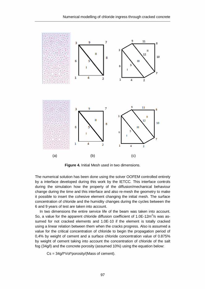
Numerical modelling of chloride ingress through cracked concrete
97
(a) (b) (c)
Figure 4. Initial Mesh used in two dimensions.
The numerical solution has been done using the solver OOFEM controlled entirely by a interface developed during this work by the IETCC. This interface controls during the simulation how the property of the diffusion/mechanical behaviour change during the time and this interface and also re-mesh the geometry to make it possible to insert the cohesive element changing the initial mesh. The surface concentration of chloride and the humidity changes during the cycles between the 6 and 9 years of test are taken into account.
In two dimensions the entire service life of the beam was taken into account. So, a value for the apparent chloride diffusion coefficient of 1.0E-12m2/s was as-sumed for not cracked elements and 1.0E-10 if the element is totally cracked using a linear relation between them when the cracks progress. Also is assumed a value for the critical concentration of chloride to begin the propagation period of 0,4% by weight of cement and a surface chloride concentration value of 0.875% by weight of cement taking into account the concentration of chloride of the salt fog (34g/l) and the concrete porosity (assumed 10%) using the equation below:
Cs = 34g/l*Vol*porosity/(Mass of cement).

Numerical modelling of chloride ingress through cracked concrete
98
Figure 5 shows that the chloride threshold value would be reached on the tensile zone and no micro-cracks existence is considered, in about 24 years. This result explains the reason why the reinforcement located on compressive zone has a low amount of corrosion after 26 years.
Taking into account in the simulation the presence of micro-cracks located in tensile zone since of the beginning of application of the external load, it can seen in Figure 6 (a) that the chloride concentration around the rebars at tensile zone is much higher (about 100 times) than those found on profile (A). It happens be-cause in the computation it has been assumed a chloride diffusion coefficient in the cracked zone up to 100 times higher. This assumption seems to be close of the real behaviour.
(b) (B)
Figure 5. Chloride concentration distribution after 24 years not considering the presence of the micro-cracks.

Numerical modelling of chloride ingress through cracked concrete
99
(a) (A)
Figure 6. (a) Chloride concentration distribution considering the presence of mi-cro-cracks found since of the beginning caused by the external loads. (A) Chloride concentration distribution not considering the presence of the micro-cracks.
3. The pattern of fracture
To save computational resources, a simulation of the fracture behaviour in two-dimensions has been carried out in a section of the beam to determine the pattern of fracture caused by the increase in volume of the corrosion products that has been confirmed by the experimental tests. This was accomplished by using cohe-sive elements of fracture in order to check crack growth until it is visible on the surface of the concrete.
3.1 Loss of diameter of reinforcement
To perform the numerical simulation is very important to know the loss of diameter of reinforcement as input data for the simulation. The experimental test provided by INSA shows (Figure 7) that the average loss of diameter on both front and back side bars at failure location is 21.6%. Considering that for reinforcements located at the tensile zone begins to corrode at the beginning of the test, the rate of loss of diameter is 132 microns per year.

Numerical modelling of chloride ingress through cracked concrete
100
Figure 7. Loss of diameter of reinforcement along the length provided by INSA.
With this mechanical fracture simulation we represent the crack pattern of a slice of the beam, as can seen in Figure 8, which depicts the numerical specimen rep-resenting the real crack pattern found on the real beam.
(a) (b)
Figure 8. Crack pattern of the beam provided by INSA.
Numerical modelling of chloride ingress through cracked concrete
101
4. 3D Simulation
To simulate the behaviour of the beam on both actions: the external load and the internal caused by the corrosion products, a 3-D simulation has been performed using elements of imbedded fracture in order to plot the curve of the deflection of the central region of the beam versus the external load to compare with the exper-imental data.
The numerical simulation in three dimensions was carried out to take into ac-count the load history applied to the beam. But in this case, just the propagation period has been taken into account. We assumed that all the rebar has uniform corrosion and a uniform corrosion current. The mesh was generated using Linear 3D eight – node finite elements divided into three different zones:
· Concrete bulk: Rotating crack model for concrete. Virgin material is mod-elled as isotropic linear elastic material (described by Young modulus and Poisson ratio). The onset of cracking begins, when principal stress reaches tensile strength. Further behaviour is then determined by linear softening law, governed by principle of preserving of fracture energy Gf . For large elements, the tension strength can be artificially reduced to preserve frac-ture energy. The transition to scalar damage model takes place, when the softening stress reaches the specified limit. Multiple cracks are allowed. The elastic unloading and reloading is assumed. In compression regime, this model corresponds to isotropic linear elastic material.
· Rebar: Rotating crack model for Steel.
· Interface concrete/rebar: this zone uses the same material of the concrete bulk, but works like a 1 mm thick ring to simulate the loss of adherence when this zone is cracked.
To perform the relation between the deflection of the beam and its load, a 3D numerical simulation has been performed. The problem of this kind of simulation is the fact that is very time consuming in computing terms.
In Figure 9 is shown the curve of the relation between the deflection of the cen-tral region of the beam and the external load. It can be remarked that the numeri-cal simulation presents a rigidity of the beam lower than the real experiment. Such phenomenon happens because of some possible causes: a)The assumed energy of fracture differs from the real one (it was not measured), b) The loss of diameter is not homogeneous along the rebars as assumed in the computation and c) for the simulation, the average value on the crack zone has been taken.

Numerical modelling of chloride ingress through cracked concrete
102
Figure 9. Curve of the deflection of the central region of the beam versus the external load (numerical and experimental data).
5. Conclusion
As the lower beam side bars were corroding in the moment this computation exer-cise is made, it was necessary to introduce in the 2D simulation the diffusion of chloride in presence of micro-cracks on the tensile zone, in order to reproduce the real pattern of corrosion-induced cracks on the tensile zone which was different of that of compression one. This is due to the flexural loading of the beam.
Corrosion-induced cracking has been studied to model the concrete fracture by means of a cohesive model to take into account the topological change as multiple cracks form and propagate. Present cohesive model has enabled to follow on 2D the cracking pattern and how the material is being disintegrated around the bar. This model type then will serve to study the evolution of the crack pattern at further and advanced stages of the corrosion.
The 3D simulation enabled to verify the behaviour of the beam when a coupled situation is produced: a external load is applied together with the presence of the corrosion process of the rebars. This simulation enables to approach the curve of the deflection of the central region of the beam versus the external load and com-pare it with the experimental data.
Numerical modelling of chloride ingress through cracked concrete
103
6. Acknowledgements
The authors are grateful to the facilities provided by the Commissariat à l’Energie Atomique (CEA) in France for developing present work. In particular they are grateful to Allain Millard and Valerie L’Hostis for the support given to F. Tavares during its stay in Saclay installations and for providing the corrosion data of the beams. The authors also acknowledge the funding obtained from the Ministry of Science and Innovation and the CSIC of Spain through the CONSOLIDER-SEDUREC project which had supported the visit of F. Tavares to Oxand – Paris- France.
References
1. Andrade, C., Alonso, C. and Molina, F.J. 1993.Cover cracking as a function of rebar corrosion.1. Experimental test. Mater Struct 26(162), pp. 453–464.
2. Andrade, C., Alonso, C. and Sarria, J. 1998. Influence of relative humidity and temperature on-site corrosion rates. Mater Constr. 48(251), pp. 5–17.
3. Andrade, C., Alonso, C. and Sarria, J. 2002. Corrosion rate evolution in con-crete structures exposed to the atmosphere. Cem Concr Compos. 24(1), pp. 55–64.
4. Andrade, C. and Castillo, A. 2003. Evolution of reinforcement corrosion due to climatic variations. Mater Corros. 54(6), pp. 379–386.
5. Andrade, C., Martinez, I. and Zuloaga, P. 2006. Environmental influence in the corrosion parameters registered in a buried pilot nuclear waste container. J Phys IV. 136:321–329.
6. Beverskog, B. and Puigdomenech, I. 1996. Revised Pourbaix diagrams for iron at 25–300ºC. Corrosion Science 38(12), pp. 2121–2135.
7. Coronelli, D. 2002. Corrosion cracking and bond strength modeling for corroded bars in reinforced concrete. ACI Struct J. 99(3), pp. 267–276.
8. Almusallam, A.A., AlGahtani, A.S., Aziz, A.R. and Rasheeduzzafar. 1996. Effect of reinforcement corrosion on bond strength. Constr Build Mater. 10(2), pp. 123–129.
9. Amleh, L. and Ghosh, A. 2006. Modeling the effect of corrosion on bond strength at the steel-concrete interface with finite-element analysis. Ca-nadian Journal of Civil Engineering 33(6), pp. 673–682.

Numerical modelling of chloride ingress through cracked concrete
104
10. Amleh, L. and Mirza, S. 1999. Corrosion influence on bond between steel and concrete. ACI Struct J. 96(3), pp. 415–423.
11. Rodriguez, J., Ortega, L.M. and Casal, J. 1997. Load carrying capacity of concrete structures with corroded reinforcement. Constr Build Mater. 11(4), pp. 239–248.
12. Ruiz, G., Elices, M. and Planas, J. 1999. Size effect and bond-slip depend-ence of lightly reinforced concrete beams. Minimum Reinforcement in Concrete Members 24, pp. 67–97.
13. Ruiz, G. 2001. Propagation of a cohesive crack crossing a reinforcement layer. Int J Fract. 111(3), pp. 265–282.
14. Torres-Acosta, AA. and Martinez-Madrid, M. 2003. Residual life of corroding reinforced concrete structures in marine environment. Journal of Materials in Civil Engineering. 15(4), pp. 344–353.
15. Torres-Acosta, A.A., Navarro-Gutierrez, S. and Teran-Guillen, J. 2007. Residual flexure capacity of corroded reinforced concrete beams. Engineering Structures 29(6), pp. 1145–1152.
16. Cabrera, J.G. 1996. Deterioration of concrete due to reinforcement steel cor-rosion. Cem Concr Compos 18(1), pp. 47–59.
17. Castel, A., Francois, R. and Arliguie, G. 2000. Mechanical behaviour of cor-roded reinforced concrete beams – Part 1: Experimental study of corroded beams. Mater Struct 33(233), pp. 539–544.
18. Coronelli, D. and Gambarova, P. 2004. Structural assessment of corroded reinforced concrete beams: Modeling guidelines. J Struct Eng-ASCE 130(8), pp. 1214–1224.
19. Bhargava, K., Ghosh, A.K,. Mori, Y. and Ramanujam S. 2007. Corrosion-induced bond strength degradation in reinforced concrete – Analytical and empirical models. Nucl Eng Des 237(11), pp. 1140–1157.
20. Dagher, H.J. and Kulendran, S. 1992. Finite-element modeling of corrosion damage in concrete structures. ACI Struct J 89(6), pp. 699–708.
21. El Maaddawy, T., Soudki, K. and Topper, T. 2005. Computer-based mathe-matical model for performance prediction of corroded beams repaired with fiber reinforced polymers. Journal of Composites for Construction 9(3), pp. 227–235.

Numerical modelling of chloride ingress through cracked concrete
105
22. Berra, M., Castellani, A., Coronelli, D., Zanni, S. and Zhang, G. 2003. Steel-concrete bond deterioration due to corrosion: finite-element analysis for different confinement levels. Mag Concr Res 55(3), pp. 237–247.
23. Lundgren, K. 2002. Modelling the effect of corrosion on bond in reinforced concrete. Mag Concr Res 54(3), pp. 165–173.
24. Bhargava, K., Ghosh, A.K, Mori, Y. and Ramanujam, S. 2006. Analytical mod-el for time to cover cracking in RC structures due to rebar corrosion. Nucl Eng Des 236(11), pp. 1123–1139.
25. Xu, G., Wei, J., Zhang, K.Q. and Zhou, X.W. 2007. A calculation model for corrosion cracking in RC structures. Journal of China University of Geo-sciences 18(1), pp. 85–89.
26. Bhargava, K., Ghosh, A.K, Mori, Y. and Ramanujam, S. 2006. Model for cover cracking due to rebar corrosion in RC structures. Engineering Structures 28(8), pp. 1093–1109.
27. Vidal, T., Castel, A. and Francois, R. 2004. Analyzing crack width to predict corrosion in reinforced concrete. Cem Concr Res 34(1), pp. 165–174.
28. Du, Y.G., Chan, A.H.C. and Clark, L.A. 2006. Finite element analysis of the effects of radial expansion of corroded reinforcement. Computers & Structures 84(13–14), pp. 917–929.
29. El Maaddawy, T. and Soudki, K. 2007. A model for prediction of time from corrosion initiation to corrosion cracking. Cem Concr Compos 29(3), pp. 168–175.
30. Ruiz, G., Ortiz, M. and Pandolfi, A. 2000. Three-dimensional finite-element simulation of the dynamic Brazilian tests on concrete cylinders. Int J Numer Methods Eng 48(7), pp. 963–994.
31. Ruiz, G., Pandolfi, A. and Ortiz, M. 2001. Three-dimensional cohesive modeling of dynamic mixed-mode fracture. Int J Numer Methods Eng 52(1–2), pp. 97–120.
32. Ortiz, M. and Pandolfi, A. 1999. Finite-deformation irreversible cohesive elements for three-dimensional crack-propagation analysis. Int J Numer Methods Eng 44(9), pp. 1267–1282.
33. Yu, R.C. and Ruiz, G. 2006. Explicit finite element modeling of static crack propagation in reinforced concrete. Int J Fract 141(3–4), pp. 357–372.

Numerical modelling of chloride ingress through cracked concrete
106
34. Ahmed, S.F.U., Maalej, M. and Mihashi, H. 2007. Cover cracking of reinforced concrete beams due to corrosion of steel. ACI Mater J 104(2), pp. 153–161.
35. Wang, X.H. and Liu, X.L. 2004 Modeling bond strength of corroded reinforcement without stirrups. Cem Concr Res 34(8), pp. 1331–1339.
36. Pantazopoulou, S.J. and Papoulia, K.D. 2001. Modeling cover-cracking due to reinforcement corrosion in RC structures. Journal of Engineering Mechanics-Asce 127(4), pp. 342–351.
37. Camacho, G.T. and Ortiz, M. 1996. Computational modelling of impact damage in brittle materials. International Journal of Solids and Structures 33(20–22), pp. 2899–2938.
38. Molina, F.J, Alonso, C. and Andrade, C. 1993. Cover cracking as a function of rebar corrosion. 2. Numerical model. Mater Struct 26(163), pp. 532–548.
39. Khan, I., François, R. and Castel, A. 2011. Mechanical Behavior of Long–Term Corroded Reinforced Concrete Beam. RILEM Bookseries 5, pp. 243–258.

Effect of different repair techniques on the hygrothermal performance of concrete facades
107
Effect of different repair techniques on the hygrothermal performance of
concrete facades
F. Al-Neshawy, J. Piironen, E. Sistonen, J. Puttonen Aalto University, School of Engineering,
Department of Civil and Structural Engineering, Espoo, Finland ABSTRACT: Building facades constructed of concrete are common for many residential and in-stitutional buildings. Most of the facades constructions used in Finland during the 60’s and 70’s were sandwich element facades. The structure of sandwich elements consists of an outer and inner panel made of concrete, with thermal insulation in between them. The insulation can be mineral wool, polyurethane or polystyrene. The concrete panels of sandwich elements are joined together using trusses. Part of these sandwich facades have been repaired during the last 20 years. One major factor in the physical deterioration of these facades is the environmental exposure with cyclic changes of moisture and temperature. Concrete building facade deterioration may occur for two principal reasons: corrosion of the embedded steel due to carbonation and freezing-thawing damage of the concrete. Concrete deterioration is usually related to moisture, and is typically in the form of cracking, spalling and delamination of the concrete. The continuous monitoring of moisture and temperature is used to ensure that the building facade is functioning as planned.
The aim of this paper is to present the results of the field monitoring of moisture and temperature of three concrete facades repaired with different methods. The first facade was repaired by demolishing the outer concrete panel and the insulation. New mineral wool insulation was added and the original outer concrete panel was replaced by a cladding of bricks with a ventilation gap. The second facade was repaired by adding external EPS insulation and a rendering system. The third facade was repaired by adding external mineral wool insulation and a rendering system. The moisture and temperature of the different layers of the facades were measured at regular interval of 1 hour since the year 2004. The field monitoring was carried out using the RHT-MS monitoring network system, which was developed for this purpose.
The results of moisture and temperature monitoring provide an opportunity to take a closer look at the hygrothermal performance of the wall assembly and the effect of different repairing methods on it.
1. Introduction
Moisture originated damage can be divided into three types of deterioration processes: biological, chemical, and physical which may lead to mechanical and

Effect of different repair techniques on the hygrothermal performance of concrete facades
108
structural degradation in the form of loss of stiffness, excessive deformation, cracking, delamination, spalling, and, in severe cases, to structural failure. (Carmeliet et. al. 2009)
Concrete building facade deterioration may occur for two principal reasons: corrosion of the embedded steel resulting in concrete deterioration, and degradation of the concrete itself. Concrete deterioration due to corrosion of embedded steel is usually related to moisture, and is typically in the form of cracking and delamination of the concrete. Freeze-thaw damage results from the freezing of concrete that is saturated with water. This type of damage appears as degradation of the surface, including severe cracking, extending into the concrete. Alkali-aggregate reactions result when alkalis normally present in cement react with silicious aggregates in concrete that is exposed to moisture. The reaction produces a toothpaste-like gel that develops over years or decades until the forces created expand and crack the concrete. (Lemieux 2009).
One goal of this study was to develop a moisture and thermal monitoring method help to understand the moisture and thermal performance of the repaired building facades. For that purpose, the RHT-MS network and RHT-MS monitoring software were developed. For testing the developed RHT-MS monitoring network, a field research was carried out for monitor the relative humidity and temperature of two facades that were repaired using different methods.
This paper is presenting the result of the field monitoring of moisture and temperature of three repaired concrete facades and the effect of their different methods.
1.1 Repairing of building facades
The building facade repair process involves determining the cause of the defects and their effect, concrete evaluation, analysis, and choosing the repair strategy. The choice of repair method and repair material depends to a great extent on the correct and accurate interpretation of the results the accurate identification of the cause of building façade degradation (Pretorius 2001). According to Haukijärvi (2006), the concrete facade renovation methods can be classified as protective repair methods, additional thermal insulation and cladding, or demolition of outer layer and rebuilding. Alternatives of common repair methods for concrete facades are shown in Figure 1.

Effect of different repair techniques on the hygrothermal performance of concrete facades
109
Figure 1. Alternative repair methods for concrete facades.
Protective repair methods are suitable mainly for structures where deterioration has just begun and the damage is not widespread. Potential protective repair methods suitable for concrete facades are divided into:
· Resealing of element joints with elastic sealants · Painting over the old paint · Protective painting after removal of old paint · Thorough patch repair and protective painting.
Additional thermal insulation and cladding methods are used with severely damaged structures, but the original outer façade leaf is to be preserved. The original structure is covered with an additional thermal insulation and a new outer layer as shown in Figure 2.
The common cladding systems are:
· Cladding brick wall or concrete facade elements · External thermal insulation with rendering coats · Different facade panel products (metal cassettes, fibre cement panels,
polymer composite panels, etc.).
Effect of different repair techniques on the hygrothermal performance of concrete facades
110
Thermal insulation, ventilation gap and cladding bricks
Thermal insulation and rendering coat
Thermal insulation and cladding panels
Figure 2. Additional thermal insulation and cladding methods for concrete facades (Haukijärvi 2005).
Replacement of the original outer façade panel is the most extreme procedure and has to be considered if the facade is damaged severely and the outer panel is strongly weathered. In this case, the method of repair can be the building of a new facade panel with outside insulation and a rendering system or rain screen cladding. The old outer leaf can be demolished if it is too weak to be anchored or bolted to the inner panel.
1.2 Hygrothermal performance of building facades
The exterior walls are primarily subjected to wind, moisture and thermal load gradients. Moisture in the wall materials can come from many sources: (exterior) rain and snow, (interior) condensation of indoor water vapour, soil and underground water and moisture during construction or renovation (Mukhopadhyaya 2003). The sources of moisture in building envelope walls are shown in Figure 3.
Figure 3. Sources of the moisture in the building envelop wall materials (Holm 2003).

Effect of different repair techniques on the hygrothermal performance of concrete facades
111
Hygrothermal (combined heat-air and moisture) performance in building facades prescribes to a large extent the durability and service life of the building facades. The dominant role of hygrothermal performance on the resistance to deterioration is mainly because hygrothermal processes can occur in all three states namely vapour, liquid and ice. Deterioration can exist in different forms:
· surface damage (discolouring by efflorescence), · aging processes (chemical changes, moisture induced salt migration), · structural cracking (due to thermal and moisture change), · spalling caused by freeze-thaw action, · corrosion of steel, and · mould or bacteria growth.
The hygrothermal performance of a building envelope depends on the integral performance of the building envelope system under consideration and its subsystems (Salonvaara. and Karagiozis 2003).
The magnitude and nature of the hygrothermal loads vary with time and the hygrothermal response of building materials and wall systems are also time dependent. The hygrothermal performance of an external wall assembly depends on the following facts:
· the outdoor air conditions · the indoor air conditions · the wall assembly solution and used materials.
1.3 Thermal and moisture definitions
1.3.1 Water vapor content
The vapour pressure of water that can be held by the atmosphere is called saturation pressure, which can be assumed to be dependent only on temperature. The saturated water vapour pressure is calculated according to the German standard DIN 4108-5 “Heat insulation in buildings; Calculation methods” as shown in Equation 1.
( ) *100
n
sTp T a bæ ö= +ç ÷
è ø (1)
where:
ps is the saturated vapour pressure, Pa
T is the temperature, °C
a, b & n
are constants a = 288.68 Pa, b = 1.098, and n = 8.02 for 0 ≤ T ≤ 30°C a = 4.689 Pa, b = 1.486, and n = 12.3 for -20 ≤ T < 0°C.

Effect of different repair techniques on the hygrothermal performance of concrete facades
112
The amount of water vapour that can be held by the atmosphere depends on saturated water vapour pressure as shown in Equation (2) according to the German standard DIN 4108-5 “Heat insulation in buildings; Calculation methods.”
( ) ( ) ** (273.15 )
Ws s
Mv T p TR T
æ ö= ç ÷+è ø
(2)
where:
vs is the saturated water vapour content, g/m³ ps is the saturated vapour pressure, Pa R is the gas constant, J/(K.mol). (R = 8.3145 J/(K.mol)) T is the temperature, °C Mw is the molecular weight of water, g/mol (Mw = 18.01528 g/mol).
1.3.2 Saturation deficit
The saturation deficit of the ventilation gap is the difference between the saturation water vapour content in the ventilation gap air and the actual water vapor content in the outdoor ambient air at the same temperature (Lehtinen and Viljanen 2001).
, ( , 100%) , ( , )a a as s gap T RH a outdoor T RHD V V== -
(3)
where:
Ds is the drying potential between the ventilation gap and outdoors, g/m³
vs, gap is the saturated water vapour content of the ventilation gap, g/m³
va, outdoor is the actual water vapour content outdoors, g/m³
Ta is the actual temperature, °C
RHa is the actual relative humidity, %.

Effect of different repair techniques on the hygrothermal performance of concrete facades
113
2. Field monitoring using RHT-MS monitoring network system
2.1 Monitoring network system
Figure 4. Schematic diagram of the (RHT-MS) monitoring network system (Al-Neshawy 2007).
The RHT-MS network consists of a controller (LIC04) and nodes to which the relative humidity and the temperature sensors are connected. The controller provides configuration services and enables communication with the data acquisition system. The network system may contain up to 200 nodes connected to a twisted-pair CAT5 cable with a maximum total length of 1000 meters. A schematic diagram of the RHT-MS monitoring network system is illustrated in Figure 4.
2.2 Installing of the monitoring network
The monitoring of humidity and temperature using RHT-MS-monitoring network system was carried out in three sandwich-type building facades repaired with different methods, as shown in Figure 5. The first facade (I) was repaired by adding a new insulation, ventilation gap and cladding with bricks after removing the outer leaf of the original sandwich panel and insulation. The second facade (II) was repaired by adding external insulation (EPS) and a rendering coat over the original sandwich panel. The third facade (III) was repaired by adding external mineral wool insulation and a rendering coat over the original sandwich panel.

Effect of different repair techniques on the hygrothermal performance of concrete facades
114
Facade (I) Facade (II) Facade (III)
Figure 5. Positions of the humidity and temperature sensors installation in the repaired concrete facades (I), (II) and (III).
2.3 RHT-MS monitoring network sensors
The relative humidity and temperature sensors installed in all of the repaired facades are shown in Table 1. The relative humidity and temperature sensors were installed at points 1, 2, 3, 4 and 5, as shown in Figure 4. There were also two relative humidity and temperature sensors for outdoors measurements.
Table 1. Humidity and temperature sensors used on the monitoring system.
Sensor Humidity and temperature sensor Monitored parameters and location
HMP 44 Accuracy of ±2% to ±3% RH Relative humidity of the original outer concrete panel and outdoors
SHT15 Accuracy of ±2% to ±4% RH and ±0.3°C
Relative humidity of the original insulation, the new external insulation and the rendering system
PT100 Platinum resistance thermometer. Accuracy of ±0.3°C at 0°C
Temperature of the original insulation, the original outer concrete panel, the new external insulation, the rendering system and outdoors

Effect of different repair techniques on the hygrothermal performance of concrete facades
115
3. Results and data analysis
3.1 Using ventilated exterior wall
The ventilated exterior wall assembly includes an exterior cladding wall portion, ventilation gap, wind barrier, thermal insulation, and interior wall portion. The main idea behind using the external facade cladding is to serve aesthetic and protective purposes. The protective features of covering materials are to increase mechanical strength, increase resistance to thermal shocks, and reduce water absorption.
The purpose of the gap is to remove excess moisture from the structure by the flow of air, and keep it dry to ensure proper functioning. The air flow in the gap is normally upwards. Openings are designed at the bottom to allow the air to enter the gap. In the gap the air warms, picking up moisture and flows up until released through the openings at the top of the wall. A wind barrier is used to stop the wind from blowing through thermal insulation and from causing forced convection in the insulation. This would have a negative impact on the thermal performance of the insulation. The wind protection should also have relevant moisture vapour transfer capability in order to transfer moisture vapour into the ventilated air gap.
Figure 6 presents the average daily temperature of the ventilation gap air and the outdoor ambient air. The temperature in the ventilation gap was always higher than the temperature outdoors, which increased the air movement from the ventilation gap outdoors.
Figure 6. The daily average temperature outdoors and inside the ventilation gap of the repaired facade (I) between August 2004 and February 2007.
To describe the drying potential of the ventilation gap and the façade wall, the saturation deficit was calculated using Equation 3. The saturation deficit of the ventilation gap is the difference between the saturation water vapour content in the ventilation gap air and the actual water vapour content in the outdoor ambient air at the same temperature (Lehtinen et al. 2001). As shown in Figure 7, the drying

Effect of different repair techniques on the hygrothermal performance of concrete facades
116
potential at the ventilation gap was higher during the hottest months of the year. The maximum values of the vapour saturation deficit were 29.6 and 27.8 g/m³ during July 2006 in the southeast and southwest respectively.
Figure 7. The saturation deficit in the ventilation gap of the repaired facade (I).
3.2 Adding external insulation with rendering coat
Adding external insulation with rendering coat involves mechanical and adhesive fixing of insulation boards on the outside of a building, which is then covered with mesh reinforcement, a base coat and a final decorative finish. This layered method encloses the original facade and helps to prevent heat from escaping from the building unnecessarily. The effect of adding external insulation with rendering coat is to improve the thermal performance of the original façade, reduce thermal bridging, minimize condensation and heat loss, and transfer the dew-point outside the structural wall element.
3.2.1 Effect on the thermal performance of the original facade
The effect of adding extra EPS insulation wall and a rendering coat on the thermal performance of the original facade is shown in Figure 8. The results show that the minimum temperature under the new EPS insulation layer, original outer concrete façade, and the surface of the original mineral wool insulation dropped below 0°C twice during February 2006, while the temperature of the rendering coat and outdoor ambient air was -24°C. The minimum temperature on the surface of the original inner concrete panel was +12°C during February 2006. During July 2006 the maximum temperature on the surface of the original inner concrete panel was +32°C, while the temperature of the outdoor air was +30°C.

Effect of different repair techniques on the hygrothermal performance of concrete facades
117
Figure 8. The effect of the EPS insulation on the temperature of the original facade between June 2005 and February 2007 for the repaired façade (II).
The effect of adding extra mineral wool insulation wall and a rendering coat on the thermal performance of the original facade is shown in Figure 9. The minimum temperature under the new insulation layer and the original outer concrete dropped shortly below 0°C twice during February 2006, while the temperature of the rendering coat and outdoor ambient air was -26°C. The minimum temperature on the surface of the original inner concrete panel was +14°C during February 2006. During July 2006 the maximum temperature on the surface of the original inner concrete panel was +33°C, while the temperature in outdoor air was +31°C.
Figure 9. The effect of the mineral wool insulation on the temperature of the original facade between June 2005 and February 2007 for the repaired façade (III).
3.2.2 Drying of the original concrete façade
Figure 10 shows the drying of the original outer panel of the sandwich concrete façade (II) after one and a half years of the installation of the external wall insulation and the rendering coat. The relative humidity of the outer concrete

Effect of different repair techniques on the hygrothermal performance of concrete facades
118
panel, where EPS (50 mm) was used, dropped from 97% to 67% in the façade facing the northeast and 63% in the façade facing the southwest between June 2005 and February 2007. The water vapour content of the outer concrete panel dropped from 24 g/m³ (northeast) and 29 g/m³ (southwest) to 6 g/m³ between June 2005 and February 2007. The water vapour content of the original outer concrete panel of the repaired facade (II) decreased during the winter of 2005–2006 down to 3 g/m³, and then increased again to 20g/m³ during the following summer. The water vapour content was still 70% and 80% drier than at the repairing time in northeast and southwest respectively.
Figure 10. The relative humidity and water vapour content of the original outer concrete panel of the repaired façade (II).
Figure 11 shows the drying of the original outer panel of the repaired façade (III) after one and a half years of the installation of the external mineral wool insulation (70 mm) and the rendering coat. The relative humidity of the outer concrete panel dropped from 88% to 67% in the façade facing southwest and from 64% to 54% in the façade facing northeast between June 2005 and February 2007. The water vapour content of the outer concrete panel dropped from 16 g/m³ (northeast) and 23 g/m³ (southwest) to 4 and 6 g/m³ respectively between June 2005 and February 2007. The water vapour content of the original outer concrete panel of the repaired facade (III) decreased during the winter of 2005–2006 down to 2 g/m³, and then increased again to 15 g/m³ during the following summer. The water vapour content was still 60% lower than the repairing time in southwest. In general, buildings facades gradually achieve moisture equilibrium by releasing moisture during the first and second years after repairing and their moisture content increases during the humidity of summer, and decreases during the dryness of winter.

Effect of different repair techniques on the hygrothermal performance of concrete facades
119
Figure 11. The relative humidity and water vapour content of the original outer concrete panel of the repaired façade (III).
4. Conclusions
Monitoring equipment is becoming more reliable, easier to use and more economical. The temperature and relative humidity devices fall into two categories: those that provide a record of conditions at a specific period of time and those that provides a continuous record of the conditions. The RHT-MS monitoring network system is used for long-term monitoring of thermal and moisture conditions.
The field monitoring research was carried out to monitor the relative humidity and temperature of three facades that were repaired with different methods in two cardinal directions. The first façade was repaired by demolishing the outer panel and insulation of sandwich panel and by adding new mineral wool insulation and cladding of bricks with a ventilation gap. The second and third facade was repaired by external wall insulation and rendering system. The main target of the research was to check the thermal and moisture performance of the facade walls that were repaired with different repairing methods and materials.
The temperature in the ventilation gap was always higher than the temperature outdoors, which increased the air movement from the ventilation gap outdoors. The drying potential at the ventilation gap was higher during the hottest months of the year.
The advantage of external insulation walls is that they improve the thermal performance of the original wall, reduce thermal bridging, minimize condensation and heat loss, reduce thermal stress on the structure, and transfer the dew-point outside the structural wall element.
The results of the thermal and moisture monitoring of facades repaired by adding external wall insulation and rendering system show drying of original outer concrete panel of the repaired façade after one year from repairing. The insulation wall thickness has an impact on the drying of the original façade: the thicker the insulation faster the drying of the façade wall.
The external insulation and rendering system is a preferred method for repairing existing building facades for economic and environmental reasons. Its main advantage is that the original outer façade leaf is preserved and no
Effect of different repair techniques on the hygrothermal performance of concrete facades
120
demolishing is needed and it is usually possible to install the insulation while the building is in use, thus reducing the disturbance to the occupier and the additional cost of decanting the occupants. Based on the hygrothermal performance of the repaired facades, It also makes it possible to deal with heat and moisture transfer problems in a more comprehensive way.
References
Al-Neshawy, F. 2007. A Network system for monitoring the thermal and moisture performance of repaired concrete facades. Licentiate Thesis, Helsinki University of Technology, Faculty of Engineering and Architecture, Department of Structural Engineering and Building Technology, Espoo, Finland, 2007. 127 p.
Carmeliet, J., Roels, S. and Bomberg, M.T. 2009. Towards development of methods for assessment of moisture-originated damage. Chapter 28 in Moisture Control in Buildings: The Key Factor in Mold Prevention, MNL18-2nd, edited by Heinz R. Trechsel and Mark Bomberg-2nd ed., ASTM international. Pp. 591–605.
DIN 4108-5. Heat insulation in buildings; Calculation methods” 81/08/00.
Haukijärvi, M. and Lahdensivu, J. 2005. JUKO: Technical documentation for the repairing of building facades (in Finnish: JUKO -ohjeistokansio). Tampere university of technology, Finland. Online at: http://www.julkisivu yhdistys.fi/julkkari/juko/. (Accessed 12.12.2012.)
Haukijärvi, M., Lahdensivu, J. and Pentti, M. 2006. Finnish manual for facade repair systems. Proceedings of the European symposium on service life and serviceability of concrete structures, ESCS2006. 12–14 June, 2006. Espoo, Finland. Pp. 359–364.
Holm, A. and Künzel, H.M. 2000. Non-isothermal moisture transfer in porous building materials. Proceedings of the materials week 2000, International congress on advanced materials, their processes and applications, 25–28 September, 2000. Munich, Germany. 9 p.
Lehtinen, T. and Viljanen, M. 2001. A new approach for the hygrothermal design of building structures” Laboratory of structural engineering and building physics, Helsinki university of technology, Espoo, Finland. 30 p. + app. 58 p. (In Finnish.)
Effect of different repair techniques on the hygrothermal performance of concrete facades
121
Lemieux, D.J. and Totten, P.E. 2009. Building Envelope Design Guide – Wall Systems. http://www.wbdg.org/design/env_wall.php Accessed 15.8.2012.
Mukhopadhyaya, P., Kumaran, K., Rousseau, M.Z., Tariku, F., van Reenen, D. and Dalgliesh, W.A. 2003. Application of hygrothermal analyses to optimise exterior wall design. The proceedings of the 2nd international conference on research in building physics. 14. September, 2003. Leuven, Belgium. Pp. 417–426.
Pretorius, J. 2001. Volume prediction for concrete repair. Faculty of engineering, Rand Afrikaans University. Johannesburg, South Africa. 122 p. + app.
Salonvaara, M.H. and Karagiozis, A.N. 2003. Influence of waterproof coating on the hygrothermal performance of a brick facade wall system. ASTM Special Technical Publication, 1314, ASTM Symposium on Water Leakage Through Building Facades (Orlando, Florida, U.S.A. 17.3.1996), (NRCC-40129) (ASTM-STP-1314), 1998. Pp. 295–311.
Effect of supplymentary cements on minimising chloride ingress in high performance concrete
122
Effect of supplymentary cements on minimising chloride ingress in high
performance concrete
M.R. Jones, Z.T. Song, H.R. Xu Concrete Technology Unit, School of Civil Engineering, University of Dundee,
Scotland, UK ABSTRACT: An experimental investigation was designed to evaluate the chloride resistance of high performance concrete containing supplementary cementitious materials in both binary and ternary systems by using the Rapid Chloride Permea-bility test (ASTM C 1202) and Rapid Migration Test (NT BUILD 492). The results demonstrated that the incorporation of fly ash in concrete exhibited higher chloride resistance than 100% PC reference concretes, and the addition of silica fume and metakaolin as third cement gave further benefits compared to FA blended con-crete on durability properties. The ternary mix (60%PC/30%FA/10%SF) indicated best performance among all tested mixes on resisting chloride attack during the test period for w/c ratio of 0.35, 0.40 and 0.45. Replacement of 10% LS as ternary components cannot improve compressive strength development compared to corresponding binary control concretes, and showed different effect on permeabil-ity and chloride ingress in concretes. The results from the Rapid Chloride Perme-ability test and Rapid Migration test showed a good correlation between each other. There was no significant improvement on durability properties by reducing w/c ratio in ternary mixes at later age.
Keywords High performance concrete; chloride ingress; fly ash; ground granu-
lated blast furnace slag; silica fume
1. Introduction
The concept of high performance concrete [1–5] is that it is specifically designed for a particular application (and therefore should not be confused with high strength concrete), which usually contains one or more cementitious material, typically fly ash (FA), ground granulated blast furnace slag (GGBS), limestone (LS), silica fume (SF) and metakaolin (MK).
It is established that Portland cement blended with these cementitious materials results into improved durability properties of concrete, particularly regarding chloride resistance. Many studies on this subject have been completed [6–9].The literature has reported [10, 11] that combinations with a third cement can offer further benefits. The main cement combinations tested comprised FA up to 35% and GGBS up to 90%. The third blended cement was LS up to 35%, SF up to 10%, and MK up to

Effect of supplymentary cements on minimising chloride ingress in high performance concrete
123
15%.Therefore, this study aims to investigate the effectiveness of these cementitious materials on chloride resisting properties of high performance concrete.
2. Experimental details
2.1 Materials
The cements used in this study were Portland cement (PC) complying with BS EN 197-1 (2000) CEM 1 42.5 N, fly ash equivalent to BS EN 450:2005, ground granu-lated blast furnace slag manufactured according to BS EN 15167: 2006, limestone according to BS 7979:2001, condensed silica fume and metakaolin conforming to BS EN 13263: 2005 and BS 8500: 2006, respectively. The physical and chemical properties of these materials are given in Table 1. A high range water reducing admixture conforming to BS EN 934 (BSI, 2008) was used in all mixes in order to maintain consistency.
2.2. Concrete mixes
The mixes were designed initially by following the procedure according to the British Research Establishment (BRE) mix design method. Considering both me-chanical and durability properties of high performance concrete, the mix propor-tions of binary systems were designed referencing from the studies of cement combinations in Dundee University, with 30% and 50% replacement of PC by FA and GGBS, respectively. The replacement level of the third blended cement was designed with 10% for LS, 15% for MK, and 10% addition for SF. The final mix designs were obtained after having done many trials as to achieve a slump be-tween 90 and 110 mm at w/c ratios of 0.35, 0.40 and 0.45, total cement content of 400 kg/m3. The details of the concrete mixes are given in Table 2.
2.3. Test methods
2.3.1 Standard Cube Strength test
The compressive strength of the concrete was determined by crushing two cubes of 100 mm size at the age of 3, 7, 28, 56 and 90days for each mix. The test was carried out according to BS EN 12390-3.
2.3.2 Rapid Chloride Permeability test
The chloride ion permeability of concrete was determined following the procedures of ASTM C1202-97 using 50-mm thick portions as sample obtained from 100 by 300 mm concrete cylinders. The resistance of concrete against chloride ion pene-tration is expressed as an electrical indication: the total charge passed in cou-lombs during a test period of 6 hours.

Effect of supplymentary cements on minimising chloride ingress in high performance concrete
124
Table 1. Physical and chemical properties of the used cementitious materials in this study.
PHYSICAL PROPERTIES PC FA SF LS MK Fineness, (m²/kg) 414 367 22400 1550 13025 Particle Density, (g/cm³) 3.14 2.25 2.20 2.63 2.49 Loss on Ignition, (%) 1.74 6.02 2.49 42.84 0.97
Chemical composition (% by mass)
CaO 62.91 3.34 0.29 77.33 ND SiO₂ 18.77 42.13 98.41 0.12 54.53 Al₂O₃ 4.55 19.65 0.66 0.15 35.98 Fe₂O₃ 2.88 10.27 0.07 0.02 0.61 MgO 1.07 1.30 0.295 0.16 0.28 MnO 0.05 0.08 0.016 0.02 0.01 TiO₂ 0.42 1.03 0.00 ND 0.00 K₂O 0.64 2.70 0.509 ND 2.25
Na₂O 0.31 1.65 0.148 0.04 0.11 P₂O₅ 0.21 0.40 0.028 0.01 0.11
Cl 0.08 0.02 0.012 ND ND SO₃ 2.59 1.77 0.089 ND ND
ND: not detected
Table 2. mix constituent proportions for studied concretes.
MIX CODE
W/C RATIO
FREE WATER
CEMENTITIOUS MATERIALS (Kg/m3) SAND 0/4
mm
AGGREGATE
PC FA LS SF MK 4/10 mm
10/20 mm
PC35
0.35
140 400 - - - - 780 390 780
PF35 140 280 120 - - - 760 380 760
PFL35 140 240 120 40 - - 760 380 760
PFS35 140 240 120 - 40 - 730 765 730
PFM35 140 220 120 - - 60 740 370 740
PC40
0.40
160 400 - - - - 760 380 760
PF40 160 280 120 - - - 740 370 740
PFL40 160 240 120 40 - - 740 370 740
PFM40 160 220 120 - - 60 720 360 720
PC45
0.45
180 400 - - - - 735 370 735
PF45 180 280 120 - - - 720 360 720
PFL45 180 240 120 40 - - 715 360 715
PFS45 180 240 120 - 40 - 680 340 680
PFM45 180 220 120 - - 60 695 350 695
Effect of supplymentary cements on minimising chloride ingress in high performance concrete
125
2.3.3 Rapid migration test
On these cores a non-steady state migration test was performed following the method of Tang and Nilsson [12] as described in NT BUILD 492. Firstly the spec-imens are vacuum saturated with a saturated Ca(OH)2 solution. Afterwards, a voltage (for the tests described here between 30 V and 60 V) that forces the chlo-ride ions from the 10% NaCl solution to migrate into the specimens, is applied across the specimen for a limited duration. The test duration varied depends on the initial current, as prescribed by NT BUILD 492. Two specimens were tested simultaneously. After the test, the specimens are axially split. On the freshly split sections, a 0.1 M AgNO3 solution is sprayed and the chloride penetration depth is measured on each part at 7 points from the visible white silver chloride precipita-tion. This colorimetric method is described by Qtsuki [13]. For each concrete core, two penetration depths are obtained.
In this way, penetration depths were obtained for each composition and con-crete age. From the mean penetration depth, the non-steady state chloride migra-tion coefficient Dnssm can be calculated, as described in NT BUILD 492.
3. Results and discussion
3.1 Standard cube strength
The standard cube strength of control, binary and ternary blended mixes at differ-ent ages is listed in Table 3. In line with expected behavior, the standard cube strength of all concretes increased with the reductions of w/c ratio, as well as with increasing test age. Compared to 100% PC mixes, the incorporation of FA re-duced the strength development at all test ages. The reduction was pronounced especially at early age and at low w/c ratio of 0.35. The negative influence on strength was due to the dilution effect of pozzolan and the slow reaction of fly ash in concrete. Comparison of binary and ternary cement systems shows that the incorporation of the third addition can enhance strength (for 10% SF and 15% MK) or reduce (for 10% LS). With 10% SF, the strength approached that of 100% PC concretes at 28 days, and surpassed those at 90 days at w/c ratio of 0.45. The improvement in strength by adding the SF was attributed to the extremely fineness and the high reactivity, leading to the denser microstructure and stronger paste-aggregate bonding. MK at 15% exhibited a pronounced increase in strength de-velopment at early age compared to the binary references, due to higher reactivity. However, the introduction of 10% LS reduced the strength development at all ages compared to binary cement concretes (PC/FA).
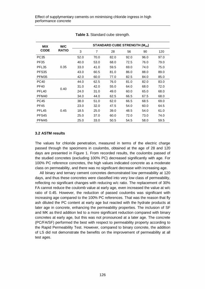
Effect of supplymentary cements on minimising chloride ingress in high performance concrete
126
Table 3. Standard cube strength.
MIX CODE
W/C RATIO
STANDARD CUBE STRENGTH (Mpa)
3 7 28 56 90 120
PC35
0.35
52.0 70.0 82.0 92.0 96.0 97.0 PF35 40.0 53.0 68.0 72.5 76.0 79.0 PFL35 33.0 41.0 59.5 69.0 74.0 75.0 PFS35 43.0 60.5 81.0 86.0 88.0 89.0 PFM35 42.0 60.0 77.0 82.5 84.0 85.0 PC40
0.40
44.0 62.5 76.0 81.0 82.0 83.0 PF40 31.0 42.0 55.0 64.0 68.0 72.0 PFL40 24.0 31.0 49.0 60.0 65.0 68.0 PFM40 34.0 44.0 62.5 66.5 67.5 68.0 PC45
0.45
38.0 51.0 62.0 66.5 68.5 69.0 PF45 23.0 32.0 47.5 54.0 60.0 64.5 PFL45 18.5 25.0 39.0 48.5 54.0 61.0 PFS45 25.0 37.0 60.0 72.0 73.0 74.0 PFM45 25.0 33.0 50.5 54.5 58.0 59.5
3.2 ASTM results
The values for chloride penetration, measured in terms of the electric charge passed through the specimens in coulombs, obtained at the age of 28 and 120 days are presented in Figure 1. From recorded results, the coulombs passed of the studied concretes (excluding 100% PC) decreased significantly with age. For 100% PC reference concretes, the high values indicated concrete as a moderate class on permeability, and there was no significant decrease with increasing age.
All binary and ternary cement concretes demonstrated low permeability at 120 days, and thus these concretes were classified into very low class of permeability, reflecting no significant changes with reducing w/c ratio. The replacement of 30% FA cannot reduce the coulomb value at early age, even increased the value at w/c ratio of 0.45. However, the reduction of passed coulombs was significant with increasing age compared to the 100% PC references. That was the reason that fly ash diluted the PC content at early age but reacted with the hydrate products at later age in concrete, enhancing the permeability properties. The inclusion of SF and MK as third addition led to a more significant reduction compared with binary concretes at early age, but this was not pronounced at a later age. The concrete (PC/FA/SF) performed the best with respect to permeability property according to the Rapid Permeability Test. However, compared to binary concrete, the addition of LS did not demonstrate the benefits on the improvement of permeability at all test ages.

Effect of supplymentary cements on minimising chloride ingress in high performance concrete
127
Figure 1. Total passed coulombs varying with age.
3.3 NT BUILD results
Figure 2 shows the values obtained for the non-steady state chloride migration coefficient as calculated from the chloride penetration depth, where each value is the average of two measurements. A lower migration value obtained at the end of the test indicates better resistance to chloride ion penetration and thus, higher durability property. The migration coefficient of these mixes in the test decreased with age and w/c ratio reduction. Among all studied mixes, the mix (PC/FA/SF) performed best regarding the resistance against chloride ingress, presenting the lowest chloride migration coefficient.
The same trend was observed in the ASTM test, where the FA addition demon-strated no improvement on lowering the chloride permeability, but resulted in an increase of the value compared to 100% PC mix at 28 days. However, the im-provement was significant with increasing age, achieving a great reduction at 120 days. The addition of LS as the third cement did not give any further benefits com-pared to the FA binary cement concretes at both 28 and 120 days. The introduc-tion of SF and MK reduced the diffusion coefficient greater than binary concretes at 28 days, but MK mix performed worse resistance than binary mix at 120 days. REMARK: for each test refer to the actual property determined; for NT Build this is the migration coefficient and not the diffusion coefficient
Having a fine particle size and spherical sharp geometry, fly ash can reduce water demand and the presence of voids between cement particles, leading to a denser structure of concrete. It possesses pozzolanic properties resulting from siliceous and aluminous ingredients, however, the reaction of fly ash in concrete needs a long time. Therefore, at an early age, the incorporation of fly ash did not

Effect of supplymentary cements on minimising chloride ingress in high performance concrete
128
improve the durability of concrete, especially at higher w/c ratio where the dilution effect was more pronounced. At a later age, the pozzolanic reaction with hydrate products makes pores finer and results into stronger bonding between aggregate and paste, achieving better durability properties. Therefore, there was a significant reduction with time elapsing. Silica fume is a very reactive material with its high content of silica and extremely fineness. Physically, silica fume particles act as nucleation sites in accelerating the hydration of tricalcium silicates (C3S) present in Portland cement, while also improving particle packing effects on concretes [14]. Secondary, pozzolanic reaction with hydrate products is beneficial for the initial interfacial transition zone (ITZ) in concrete [7,15]. The improvement on du-rability properties was pronounced at 28 days because the pozzolanic reaction started at an early age. Metakaolin is a reactive alumino silicate pozzolan, which also results into an improvement in concrete at early age. For limestone as filler having no pozzolanic properties, the addition in FA blended concrete cannot make a further improvement in durability properties although it has fineness advantage.
Figure 2. Chloride diffusion coefficients with varying age.
3.4 Correlation between the RCPT and RMT
The Rapid Chloride Permeability test was used to test the permeability of concrete by collecting total coulombs passed through, and the Rapid Migration test was applied to evaluate the non-steady state chloride migration coefficients by analyzing chloride penetration depth of concrete. Both of them are closely related to the pore structure and the chemistry of pore solution. By linear regression analysis of each other, the results show a good correlation between two test methods in Figure 3

Effect of supplymentary cements on minimising chloride ingress in high performance concrete
129
and Table 4, with high correlation coefficient, 0.9481. The concretes having a w/c ratio of 0.40 show the best correlation compared to w/c ratio of 0.35 and 0.45. The mix PFL demonstrated the highest correlation coefficient and mix PFS with the lowest value among all tested mix series.
Table 4. Correlation coefficients between coulombs and migration coefficients.
TOTAL W/C MIX SERIES
R2 0.9481 0.35 0.40 0.45 PC PF PFL PFS PFM
0.9345 0.9938 0.9515 0.8773 0.9444 0.9749 0.8502 0.9212
Figure 3. Correlation coefficient between RCPT and RMT.
4. Conclusions
The objective of this experimental investigation was to study the chloride durability properties of binary and ternary system concretes. Based on the above results and discussion, the following conclusions can be drawn:
1. The replacement of PC by FA reduced the strength development. The ad-dition of SF or MK as third blended cement can increase the strength to some extent, especially at early age, however, the strength was lower than for 100% PC reference concrete.
2. The addition of FA as a binary cement performed better on reducing chlo-ride migration coefficient compared to the 100% PC reference concretes,

Effect of supplymentary cements on minimising chloride ingress in high performance concrete
130
and the use of SF and MK as the third cement gave further benefits on im-proving chloride resistance, especially at early age.
3. The incorporation of LS in FA binary concrete did not show any further im-provement on the durability property at all test ages, according to the 2 tests applied in the study.
4. There is a good correlation between Rapid Chloride Permeability test and NT BUILD 492 test. In this study it was demonstrated that the determina-tion of the electrical conductance of concrete by the RCPT is capable of providing an indication of its resistance to the penetration of chloride ions.
5. The further improvement of chloride durability with reducing w/c ratio was slightly better for binary and ternary cement concretes at later age.
References
1. Shi, C. 2004. Effect of mixing proportions of concrete on its electrical conductivity and the rapid chloride permeability test (ASTM C1202 or ASSHTO T277) results. Cement and Concrete Research,34(3), pp. 537–545.
2. Poon, C.S. et al. 2006. Compressive strength, chloride diffusivity and pore structure of high performance metakaolin and silica fume concrete. Con-struction and Building Materials 20(10), pp. 858–865.
3. Ghrici, M. et al. 2007. Mechanical properties and durability of mortar and con-crete containing natural pozzolana and limestone blended cements. Cement and Concrete Composites 29(7), pp. 542–549.
4. Yazici, H. et al. 2010. Mechanical properties of reactive powder concrete con-taining high volumes of ground granulated blast furnace slag. Cement and Concrete Composites 32(8), pp. 639–648.
5. Bemal, S.A. et al. 2011. Effect of binder content on the performance of alkali-activated slag concretes. Cement and Concrete Research 41(1), pp. 1–8.
6. Khan, M.I. et al. 2002. Strength, permeability, and carbonation of high-performance concrete. Cement and Concrete Research 32(1), pp. 123–131.
7. Song, H.W. et al. 2007. VA estimate of the diffusivity of silica fume concrete. Building and Environment 42, pp. 1358–1367.
8. Elahi, A. et al. 2010. Mechanical and durability properties of high performance concretes containing supplementary cementitious materials. Construction and Building Materials 24(3), pp. 292–299.

Effect of supplymentary cements on minimising chloride ingress in high performance concrete
131
9. Huang, Y. et al. 2010. Investigation on phosphogypsum-steel slag-granulated blast-furnace slag-limestone cement. Construction and Building Materials 24(7), pp. 1296–1301.
10. Bai, J. et al. 2003. Chloride ingress and strength loss in concrete with different PC-PFA-MK binder compositions exposed to synthetic seawater. Ce-ment and Concrete Research 33(3), pp. 353–362.
11. Pierre, M. et al. 2011. Improvement of the early-age reactivity of fly ash and blast furnace slag cementitious systems using limestone filler, Materials and Structures 44(2), pp. 437–453.
12. Tang, L. et al. 1992. Rapid determination of chloride diffusivity of concrete by applying an electric field. ACI Materials Journal 89, pp. 49–53.
13. Qtsuki, N. et al. 1992. Evaluation of AgNO3 solution spray method for measure-ment of chloride penetration into hardened cementitious matrix materials. ACI Materials Journal 89(6), pp. 587–92.
14. Bamforth, P.B. 2004. Enhancing reinforced concrete durability. Guidance on selecting measured something is missing here for minimising the risk of corrosion of reinforcement in concrete, Concrete Society Report No. 61.
15. Justnes, H. 2002. Chapter 6. Condensed silica fume as a cement extender, Structure and performance of cements, 2nd edition. J. Bensted and P. Barnes (Eds.). Spon Press. Pp. 399–408.
Corrosion data interpretation in concrete structures
132
Corrosion data interpretation in concrete structures
C. Andrade Research Centre for Safety and Durability of Materials and Structures
CISDEM-UPM-CSIC Madrid-Spain
ABSTRACT: Concrete protects the embedded reinforcing steel until the carbonation front or the chloride threshold reaches the rebar. Thereupon a corrosion process develops. In the present paper the corrosion process is analyzed from its onset a definition of which is given. The techniques for its measurement are described and also a model for the corrosion propagation period is given as well as some alterna-tive methods by assuming a value of the corrosion rate, based on the values of the concrete resistivity. Finally, the functional relationship between the corrosion rate and the structural consequences are commented.
Keywords concrete, corrosion rate, climate, prediction
1. Introduction
The concrete is a good protector of the embedded steel until the carbonation front or the chloride threshold reach the rebar level. When the corrosion develops, four are the main structural consequences [1]: the decrease in the steel ductility, the steel cross section and the steel/concrete bond, and additionally, the stresses generated by the expansive character of the oxides produced lead into the cover cracking. Al theses consequences compromise the structural integrity and there-fore it is crucial to design the concrete to sustain the environmental aggressivity and if the corrosion is produced during the structure life, to detect and prevent further attack. This is especially important in critical structures as those in nuclear installations. In present work it is described the corrosion initiation and propaga-tion, what the corrosion rate generated means from a structural point of view, how to measure it on site and how to analyze the values from the standpoint of the calculation of the service life.
2. The corrosion process
2.1 Corrosion onset
Corrosion develops when the chlorides, beyond a certain threshold level, or the carbonation front reach the rebar. At that moment, identified as depassivation or corrosion onset, the passive layer dissolves and several iron oxides, described with the term “rust”, start to form and grow.

Corrosion data interpretation in concrete structures
133
Generally, depassivation is localized, as the chlorides or the carbonation arrive first to the surface of the rebar closest to the external surface. When the corrosion progresses, the oxides formed, first diffuse through the pores and, after that, in-duce cracking of the concrete cover. The corroded steel extends progressively with time in area and depth. The rate of this corrosion is defined as the amount of metal corroding referred to the unit of surface area and time.
Having in mind the classical Service Life model [2] of considering an Initiation and a Propagation period, the first to be briefly considered is the fact that the de-passivation process cannot be understood as an instantaneous process. In the case of chlorides this is due to the fact that the threshold may vary from one part of the bar to another owing to the several unhomogeneities of the steel and the concrete. In the case of carbonation the front arrives first to the external part of the bar and therefore the corrosion increases as referred to the total surface. Then, events of activity-passivity may develop during a long period of time.
Therefore the achievement of a situation with a constant active corrosion state may last significantly. However, during this active-passive time period the corro-sion progresses and a localized loss in cross section is produced. The fact that the definite onset may last months or years introduces a certain difficulty on the defini-tion of the end of the initiation period, ti. However if the accumulated corrosion, Cac (Integration of the Corrosion Rate, Icorr with time) is plotted instead of the instanta-neous corrosion rate (Figure 1) the identification of the end of ti can be better de-fined by a certain loss in cross section, as indicated by the figure.
Figure 1. Left: Corrosion rate in function of the time. Right: Accumulated corrosion (5 mm is suggested as limit of corrosion penetration Px).
3. Measurement techniques
The only electrochemical technique having a quantitative ability regarding the corrosion rate is based on the so-called Polarization Resistance, Rp [3]. This tech-nique has been extensively used in the laboratory as in addition it gives the corro-sion potential and the resistivity of the concrete [4–5]. It is based on the application of a small electrical perturbation to the metal by means of a counter and a refer-
0.01
0.10
1.00
0 1 2 3 4 5
Equivalent Time (Years)
Icor
r (uA
/cm
2)
-0.5
1.5
3.5
5.5
7.5
0 1 2 3 4 5
Equivalent Time (years)
Deg
ree
of c
orro
sion
(um
)

Corrosion data interpretation in concrete structures
134
ence electrode. Provided the electrical signal is uniformly distributed throughout the reinforcement, the DE/DI ratio defines Rp. The corrosion current, Icorr, is in-versely proportional to Rp, Icorr= B/Rp where B is a constant. Rp can be measured by means of D.C. or A.C. techniques [5], both of which have specific features in order to obtain a reliable corrosion current value in agreement with gravimetric losses.
3.1 On site measurements
Direct estimation of True Rp values from DE/DI measurements is usually unfeasi-ble in large real concrete structures [6]. This is because the applied electric signal tends to vanish with distance from the counter electrode, CE, rather than spread uniformly across the working electrode, WE. Therefore, the polarization resulting from the electric signals will not be uniform and it reaches a certain distance that is named the critical length, Lcrit. Hence, DE/DI measurements on large structures using a small counter electrode will provide an apparent polarization resistance (Rp
app) that differs from the true Rp value depending on the experimental condi-tions. Thus, if the metal is actively corroding, the current applied from a small CE located on the concrete surface is 'drained' very efficiently by the metal and it tends to confine itself on a small surface area. Conversely, if the metal is passive and Rp is high, the current applied tends to spread far away (e.g., around 50 cm) from the application point. Therefore, the apparent Rp,app approaches the true Rp only for actively corroding reinforcement, but when the steel is passive, the large distance reached by the current needs a quantitative treatment.
3.2 Modulated confinement of the current (guard ring) method [6]
There are several ways of accounting for a True Rp value, among which the most extended one is the use of a guard ring [6], in order to confine the current in a partic-ular rebar area, as Figure 2 depicts. The measurement is made by applying a gal-vanostatic step, lasting 30–100 seconds, from the central counter electrode. Then, from a second counter electrode located in the external ring current is applied, and this external current is modulated by means of the two reference electrodes called “ring controllers” in order to equilibrate internal and external currents, which enables a correct confinement, and therefore, calculation of Rp. By means of this electrical delimitation to a small zone of the polarized area, any localised spot or pit can be localised first, and then its measurement can be made by minimising the inherent error of Rp. Not all guarded techniques are efficient. Only that using a “Modulated Confinement” controlled by two small sensors for the guard ring control placed be-tween the central auxiliary electrode and the ring, as shown in Figure 2, is able to efficiently confine the current within a predetermined area. The use of guard rings without this control leads into too high values of the Icorr for moderate and low values, and the error introduced in the case of localized pits, is very high.
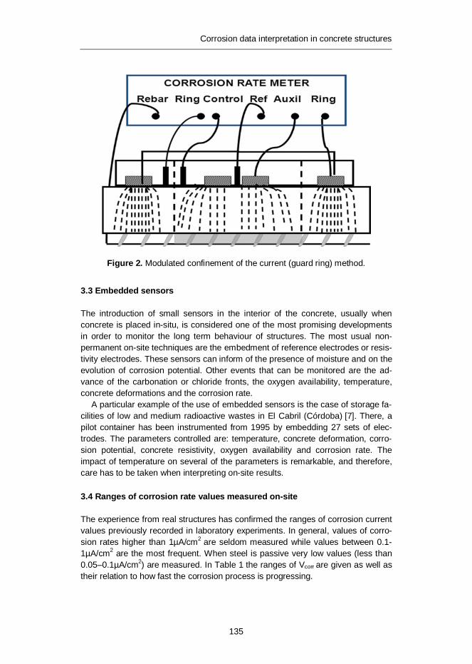
Corrosion data interpretation in concrete structures
135
Figure 2. Modulated confinement of the current (guard ring) method.
3.3 Embedded sensors
The introduction of small sensors in the interior of the concrete, usually when concrete is placed in-situ, is considered one of the most promising developments in order to monitor the long term behaviour of structures. The most usual non-permanent on-site techniques are the embedment of reference electrodes or resis-tivity electrodes. These sensors can inform of the presence of moisture and on the evolution of corrosion potential. Other events that can be monitored are the ad-vance of the carbonation or chloride fronts, the oxygen availability, temperature, concrete deformations and the corrosion rate.
A particular example of the use of embedded sensors is the case of storage fa-cilities of low and medium radioactive wastes in El Cabril (Córdoba) [7]. There, a pilot container has been instrumented from 1995 by embedding 27 sets of elec-trodes. The parameters controlled are: temperature, concrete deformation, corro-sion potential, concrete resistivity, oxygen availability and corrosion rate. The impact of temperature on several of the parameters is remarkable, and therefore, care has to be taken when interpreting on-site results.
3.4 Ranges of corrosion rate values measured on-site
The experience from real structures has confirmed the ranges of corrosion current values previously recorded in laboratory experiments. In general, values of corro-sion rates higher than 1µA/cm2 are seldom measured while values between 0.1-1µA/cm2 are the most frequent. When steel is passive very low values (less than 0.05–0.1µA/cm2) are measured. In Table 1 the ranges of Vcorr
are given as well as their relation to how fast the corrosion process is progressing.

Corrosion data interpretation in concrete structures
136
Table 1. Ranges of the corrosion rate and their relation to the velocity of the process.
Range of Vcorr (mm/year) Corrosion progression < 1 Negligeable 1–5 Low 5–10 Moderate > 10 High
4. Corrosion evolution
4.1 Influence of environment
The two parameters that influence the corrosion rate most are the moisture content in the concrete pores and the temperature. The moisture content depends on the atmospheric Relative Humidity and on the raining intensity [8]. Then, the levels of corrosion rate and its changes over time will depend on the climatic parameters.
Figure 3. evolution of Icorr of the reinforcement of a concrete specimen fully car-bonated and placed unsheltered from rain in Madrid atmosphere.
0,001
0,01
0, 1
1
10
0 200 400 600 800 1000 1200 1400 1600 1800 2000 2200 2400
T i e mp o ( d ía s )
0,001
20,001
40,001
60,001
80,001
100,001
120,001
140,001
160,001
180,001
0 200 400 600 800 1000 1200 1400 1600 1800 2000 2200 2400
Tim e (days)
Accu
mul
ated
Cor
rosi
on (u
A/cm
2)
Corrosion data interpretation in concrete structures
137
One can expect that if the concrete is maintained in chambers with constant hu-midity and temperature, the corrosion rate would remain constant as well. Howev-er, this appears not to be true because corrosion is a dynamic process in which the continuous formation of oxides and the extension or increase in depth of the local attack, makes the circumstances different in each new step. This is exempli-fied in Figure 3 corresponding to a concrete beam having in the mixing water 3% CaCl2 by cement weight and exposed to Madrid atmosphere non-sheltered from rain. The evolution of corrosion rate in open atmosphere is shown in Figure 3-left where the changes of Icorr with time are plotted. However, when plotted as Accu-mulated corrosion (Figure 3-right) the trend is much clearer and can be used for the calculation of the loss in cross section or Corrosion Penetration Px.
4.2 Determination of a representative corrosion rate
However, previously it has been shown that the corrosion rate does not have a constant value over time, neither in environments with constant humidity and tem-perature and much less when the structure is exposed to the open atmosphere. Therefore, for the correct modeling there is a need to calculate what has been named a “Representative corrosion rate, Vcorr, REP”. Its value can be the result of the integration of the instantaneous Icorr-time curves as represented in figures 2 to 5 or by the calculation of an annually averaged value. The averaging can be made in several manners depending on the number of available readings per year.
When direct readings of the corrosion rate for the particular structure are not available, another approach to estimate annual averaged values for Vcorr, REP can be to ascribe a value in function of the aggressivity of the particular environment or to estimate Vcorr, REP indirectly from other parameters, such as the pore water con-tent or the values of concrete resistivity. These alternatives for the estimation of an averaged Vcorr, REP are summarized in Table 2.
Table 2. Possibilities of estimation of the averaged corrosion rate. These three possibilities of establishing Vcorr, REP cannot be described in detail in the present paper but, for the sake of illustration, in Table 3 the following approach 2) is given of Table 2 the averaged Vcorr, REP for the exposure classes of EN 206.
AVAILABLE POSSIBILITIES OF ESTIMATION
METHOD OF ESTIMATION OF VCORR, REP
1) from direct measurements of Icorr Integration of the curves Icorr- time
2) From a Classification of ambient aggressivity
By ascribing a value to each ambient class. See Table 3
3) Indirectly, from a concrete charac-teristic related to Icorr as pore water content or concrete Resistivity
a) From pore water content by an algorithm
b) From concrete Resistivity taking account of its evolution with time and with pore water content
Table 3. Averaged corrosion rates Vcorr, REP for the exposure classes of EN206.

Corrosion data interpretation in concrete structures
138
EXPOSURE CLASS
Vcorr, REP (mm/year)
0 No risk of corrosion, very dry 0 XC1 Dry or permanent wet 0 XC2 Wet rarely dry 4 XC3 Moderate humidity 2 XC4 Cyclic wet dry 5 XD1 Moderate humidity 4 XD2 Wet, rarely dry 30 XD3 Cyclic, wet and dry 30 XS1 Airborne salt conditions 30 XS2 Submerged Not corrosion expected or 10 XS3 Tidal, splash and spray zones 70
The corrosion rate can be also calculated from the concrete resistivity as it reflects the degree of water saturation [3, 7, 9].
5. Engineering application of the corrosion rate
5.1 Basic model of corrosion propagation
A model for the propagation Period has to express the advance of corrosion with time [10]. As the accumulated corrosion has been defined as corrosion penetration Px or loss in diameter, the model can be based on the multiplication of the corro-sion rate Vcorr by the time:
Px (mm) = Vcorr (mm/year) × t (years) (1)
5.2 Damage functions for the structural consequences of the corrosion
Corrosion of the reinforcement results into several important structural damages [11–13]. The main are known to be:
· The loss of bar diameter · The loss of metal ductility · The cracking of concrete cover with the resulting loss in concrete cross section · The loss in reinforcement/concrete bond.
Reinforcement corrosion can be treated as a “limit state” in which several effects or consequences should be verified. Figure 4 [11] shows an illustration of the several effects or limit states due to corrosion to be verified as a function of Pcorr.

Corrosion data interpretation in concrete structures
139
Figure 4. Possible limit states due to corrosion to be verified as a function of cor-rosion penetration.
The verification implies the calculation of the time to reach a certain limit state, which can be now expressed in terms of corrosion propagation period, tp, as:
REPcorrp V
Pt,
lim= , (2)
where: Plim is the chosen limit of the attack penetration Px (mm) for the Limit State considered. Then, the reduced section and the loss in bond and the cover cracking should be taken into consideration for the recalculation of the damaged structural element. Table 4 gives some “damage functions” [12–16] related to the conse-quences of corrosion with the advance of the process or corrosion penetration Px.
Table 4. Some damage functions relating consequences of corrosion and corro-sion penetration.
CONSEQUENCES OF CORROSION DAMAGE FUNCTION
loss of bar diameter Px (mm) = 0.0116·Icorr, mean · a · t
loss of metal ductility Damage function not produced yet
Cover (C in mm) cracking (w = crack width in mm, Ø = bar diameter in mm and fct = indirect splitting strength)
÷÷ø
öççè
æ=
fCP
kw x with k = 5-10
spctX fCP ,333
0 10·6.2210·4.710·8.83 --- -÷øö
çèæF
+=
loss in reinforcement / concrete bond (fb)
With stirrups : fb = 5.25 - 2.72 Px
With external pressure p: fb = (4.75-4.64 Px)/(1-0.098 p)
initiation propagation
t5
t4
t3
t2
t1
possible limit states
Level of damage
timeDespasivation
Corrosion
Cracking
Section Loss
Structural Safety loss
initiation propagation
t5
t4
t3
t2
t1
possible limit states
Level of damage
timeDespasivation
Corrosion
Cracking
Section Loss
Structural Safety loss

Corrosion data interpretation in concrete structures
140
6. Final comments
In the design of a reinforced concrete structure is necessary to take into account the environment and its aggressivity in order to identify the degradation processes that may occur and to provide the measures to prevent reinforcement corrosion to occur during the service life of the structure. Although accurate models of service life do still not exist, as the available ones have not been calibrated, some approximate calculations can be undertaken. It is necessary to identify the sensitive zones of the structure and to calculate the time to corrosion onset and which will be the progres-sion of the corrosion if developed. It is desirable to foresee in these sensitive zones monitoring of the possible appearance of reinforcement corrosion. Once the loss in steel cross section is calculated, the other structural consequences can be deduced from the modification of present formulas in the Codes taken into account the reduced properties of the concrete and the reduced sections and steel/concrete bond.
7. Acknowledgements
The authors would like to acknowledge the financing of the Ministry of Science and Innovation for the INGENIO 2010-CONSOLIDER Project on “Safety and Du-rability of Structures: SEDUREC”.
References
1. Andrade, C., Alonso, C. and Molina, F. J. 1993. Cover cracking as a function of rebar corrosion: Part I – Experimental test. Materials and Structures 26, pp. 453–464.
2. Tuutti, K. 1982. Corrosion of steel in concrete. Swedish Cement and Concrete Institute, (CBI) no. 4–82, Stockholm 486.
3. Andrade, C. and Gónzalez, J.A. 1978. Quantitative measurements of corrosion rate of reinforcing steels embedded in concrete using polarization re-sistance measurements. Werkst. Korros. 29(8), pp. 515–519.
4. ASTM C876-91. standard test method for half cell potentials of uncoated rein-forcing steel n concrete.
5. Elsener, B. and Böhni, H. 1990. corrosion rates of steel in concrete. N.S. Berke, V. Chaker and D. Whiting (Eds.). ASTM STP 1065. Pp. 143–156.
6. Feliú, S., González, J.A., Feliú, S. Jr. and Andrade, C. 1990. Confinement of the electrical signal or in-situ measurement of Polarization Resistance in Re-inforced concrete. ACI Mater. J. 87(5), pp. 457–460.

Corrosion data interpretation in concrete structures
141
7. Andrade, C., Sagrera J.L., González, J.A., Jiménez, F., Bolaño, J.A. and Zu-loaga, P. 1996. Corrosion monitoring of concrete structures by means of permanent embedded sensors. Niza. Eurocorr’96.
8. Andrade, C. and Castillo, A. 2003. Evolution of reinforcement corrosion due to climatic variations. Materials and Corrosion 54(6), pp. 379–386.
9. Millard, S.G. and Gowers, K.R. 1992. Resistivity assessment of in-situ concrete: the influence of conductive and resistive surface layers. Proc. Inst. Civil Engrs. Struct. & Bldgs, 94, paper 9876, pp. 389–396.
10. Andrade, C., Alonso, C. and Rodríguez, J. 1998. Remaining service life of corroding structures, IABSE Symposium on Durability, Lisboa, (Sep 1989). Pp. 359–363.
11. Duracrete. Probabilistic performance based on durability design of concrete structures. EU-Brite EuRam Project BE95-1347. A number of reports available from CUR Centre for Civil Engineering Research and Codes, Gouda, The Netherlands.
12. Rodríguez, J., Ortega, L.M., Casal, J. and Díez, J.M. 1996. Corrosion of rein-forcement and service life of concrete structures. Proceedings of Durability of Building Materials and Components Stockholm, Vol. I. C. Sjöstrom (Ed.). E&FN Spoon Publishers. Pp. 117–126.
13. Torres Acosta, A.A. 1999. Cracking induced by localized corrosion of rein-forcement in chloride contaminated concrete. Ph. D. Thesis, University of South Florida, Florida, USA, 1999.
14. Vidal, T., Castel, A. and Francois, R. 2004. Analyzing crack width to predict corrosion in reinforced concrete. Cement and Concrete Research 34, pp. 165–174.
15. Martín–Perez, B. 1998. Service life modeling of RC highway structures ex-posed to chlorides. Ph.D. dissertation, Dept. of Civil Engineering, University of Toronto, 1998.
16. CONTECVET IN30902I. 2001. A validated users manual for assessing the residual life of concrete structures, DG Enterprise, CEC, (2001). (The manual for assessing reinforced structures affected by reinforcement cor-rosion can be seen at the web sites of IETcc (www.ietcc.csic.es) and GEOCISA (www.geocisa.es))

Service life design of concrete subject to frost attack and carbonation/ chloride penetration
142
Service life design of concrete subject to frost attack and carbonation/
chloride penetration
Erkki Vesikari, Miguel Ferreira VTT Technical Research Centre of Finland, Espoo, Finland
ABSTRACT: Traditional service life design of a reinforced concrete structure is normally based on the performance of concrete when subject to a dominating degradation mechanism. However, this rarely occurs in real-life exposure where reinforced concrete structures are subject to the simultaneous effect of several degradation mechanisms. Practical experience and research results have shown that this is not a conservative approach to SLD. The combination of several deg-radation mechanisms can result in a shorter service life due to the possible syner-getic effects which currently have not been considered in SLD.
In this paper an empirical model for the combined effect of frost attack and car-bonation/chloride penetration is presented. Based on the results of laboratory exposure tests, the effects of frost attack on the rate of carbonation and chloride penetration as an interacted degradation were developed. In addition, a procedure for service life design based on the use of interaction factors is presented where the synergistic effect of both internal frost attack and frost scaling on carbonation and chloride penetration are considered.
Results showed that, if frost attack is rapid, it is usually the dominating degra-dation mechanism, marginalising reinforcement corrosion initiated by carbonation or chloride penetration. If frost attack proceeds slowly, reinforcement corrosion can become dominant and the interaction effects should be considered in the service life design of reinforced concrete.
1. Introduction
The research results presented in this paper derive from the Finnish DuraInt re-search project – Effect of Interacted Deterioration Parameters on Service Life of Concrete Structures in Cold Environments [1–3], set up to understand the com-bined effect of degradation mechanisms such as, frost attack, carbonation and chloride penetration, on concrete performance. Although scarce, the research published on the combined effect of degradation mechanism is usually related to the effect of one specific degradation mechanism on another. Most research ad-dresses the interaction between carbonation and chloride penetration in concrete [4–6]. Research on modelling the interaction is typically based on multi-scale and numerical approaches [4–7].
Concrete infrastructure such as dams, power-plants, highways, quays, among others; located in cold climates frequently suffer from the effect of frost action

Service life design of concrete subject to frost attack and carbonation/ chloride penetration
143
during the winter periods. Frost action can result in the superficial scaling of con-crete caused by freezing of a saline solution on the surface of concrete (salt scaling), and in the internal cracking of concrete caused by cyclic freezing/thawing cycles resulting in a reduction of strength and elasticity modulus. Salt scaling and internal cracking are distinct and separate mechanisms that can occur in similar environmen-tal conditions. While salt scaling occurs in the presence of salts, internal cracking depends mainly on the uptake of water and the critical degree of saturation.
In cold climates, salts (mostly NaCl, CaCl2) are regularly used to de-ice roadways. As a result, salt scaling is one of the major durability issues facing concrete in this climate. While salt scaling alone will not render a structure useless, it results in ac-celerated ingress of aggressive species, such as chlorides. It renders the body sus-ceptible to corrosion of the reinforcing steel [8–10]. The propensity for a high degree of saturation in the presence of salts can result in strength loss from internal frost action [11–13]. Both of these effects diminish the expected lifetime of concrete [3].
Since the 1940’s much research has been done concerning the causes and mecha-nism of frost action, with the initial work of Powers [14, 15] in the USA. Microstructure of concrete became clearer even though the theories proposed could not explain all the phenomena of frost damage. Since then, much research has been done on the topic, with significant contributions by Kukko [16–19], Penttala [20] and Fagerlund [21–24]. More recently Setzer [25, 26], Marchand [27], Jacobsen [28], and Valenza [29, 30] have suggested descriptions for the phenomena of frost damage.
Despite all the advances in the research of frost attack, very little attention has been given to its effect on chloride penetration. Frost attack affects this phenome-non by reducing the concrete cover, and more importantly, by changing the char-acteristics of the surface and internal concrete due to cracking [29]. As a result, it has been shown that frost attack affects chloride penetration, but that it is not yet understood [31].
Research by Li [32] into the influence of chloride penetration by the effect of salt concentration, air-entrainment agents and the addition of silica fume in the concrete showed that there is a pessimum concentration of chloride related to the amount of scaling damage of the concrete surface. In addition, the use of air en-trainment and silica fume improved the performance of the concrete with regards to chloride penetration (measuring migration coefficients), but does not explain the moisture uptake, chloride transport and binding in the concrete.
Wang et al. [33] has simulated theoretically the cracking of concrete in the inter-facial zone, and the increase of concrete porosity. Theoretical diffusion coefficients have been compared to published results with little success, mainly as a result of the scarce availability of data.
Bouteille et al. [34] also studied chloride penetration into concrete during labor-atory testing for salt scaling. Based on the probability distribution curves of the chloride concentration fronts and that of the scaled surface they concluded that the phenomena are distinct and not interrelated. While the assumption that they are distinct is correct, they are interrelated as the consequences of frost scaling changes the properties of the concrete surface which in turn influence the penetra-tion of chlorides.
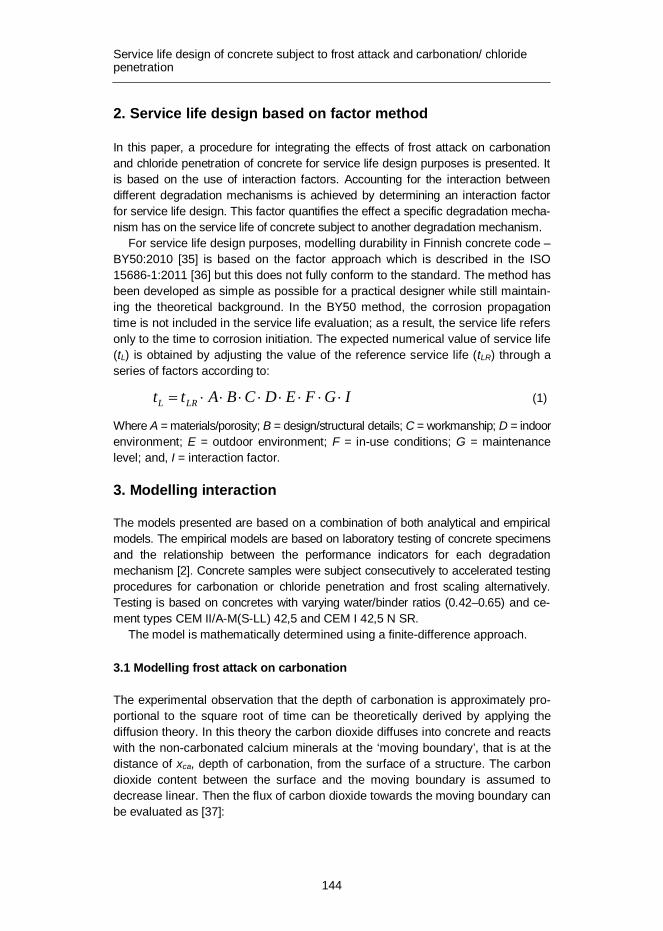
Service life design of concrete subject to frost attack and carbonation/ chloride penetration
144
2. Service life design based on factor method
In this paper, a procedure for integrating the effects of frost attack on carbonation and chloride penetration of concrete for service life design purposes is presented. It is based on the use of interaction factors. Accounting for the interaction between different degradation mechanisms is achieved by determining an interaction factor for service life design. This factor quantifies the effect a specific degradation mecha-nism has on the service life of concrete subject to another degradation mechanism.
For service life design purposes, modelling durability in Finnish concrete code – BY50:2010 [35] is based on the factor approach which is described in the ISO 15686-1:2011 [36] but this does not fully conform to the standard. The method has been developed as simple as possible for a practical designer while still maintain-ing the theoretical background. In the BY50 method, the corrosion propagation time is not included in the service life evaluation; as a result, the service life refers only to the time to corrosion initiation. The expected numerical value of service life (tL) is obtained by adjusting the value of the reference service life (tLR) through a series of factors according to:
IGFEDCBAtt LRL ××××××××= (1)
Where A = materials/porosity; B = design/structural details; C = workmanship; D = indoor environment; E = outdoor environment; F = in-use conditions; G = maintenance level; and, I = interaction factor.
3. Modelling interaction
The models presented are based on a combination of both analytical and empirical models. The empirical models are based on laboratory testing of concrete specimens and the relationship between the performance indicators for each degradation mechanism [2]. Concrete samples were subject consecutively to accelerated testing procedures for carbonation or chloride penetration and frost scaling alternatively. Testing is based on concretes with varying water/binder ratios (0.42–0.65) and ce-ment types CEM II/A-M(S-LL) 42,5 and CEM I 42,5 N SR.
The model is mathematically determined using a finite-difference approach.
3.1 Modelling frost attack on carbonation
The experimental observation that the depth of carbonation is approximately pro-portional to the square root of time can be theoretically derived by applying the diffusion theory. In this theory the carbon dioxide diffuses into concrete and reacts with the non-carbonated calcium minerals at the ‘moving boundary’, that is at the distance of xca, depth of carbonation, from the surface of a structure. The carbon dioxide content between the surface and the moving boundary is assumed to decrease linear. Then the flux of carbon dioxide towards the moving boundary can be evaluated as [37]:

Service life design of concrete subject to frost attack and carbonation/ chloride penetration
145
caxcDJ D
= (2)
Where J – flux of carbon dioxide into concrete, g/(m2s); D – diffusion coefficient with respect to carbon dioxide, m2/s; xca – distance of the moving carbonation boundary from the surface of the structure, m; Dc = cs - cx, g(CO2)/m3; cs - CO2 content of air at the surface of concrete, g/m3; and, cx- CO2 content of air at the moving boundary, g/m3.
The carbon dioxide flux into concrete must be in balance with the rate of mass growth of bound CO2:
dtdQJ ca=
(3)
Where Qca is the mass of chemically bound CO2 in concrete, kg. The mass of already bound CO2 in concrete can be presented as
caca xaQ ×= (4)
Where a is the CO2-binding capacity of concrete, kg/m3.
dtdxa
dtdQ caca =
(5)
Where t time, s. By combining Equations 2 and 5 and integrating over time (xca = 0 when t = 0),
the following solution is obtained:
atcDxca×D×
=2
(6)
From Equation 6 it can be seen that at constant conditions and with constant ma-terial properties the depth of carbonation is proportional to the square root of time. The depth of carbonation can be evaluated in a simple manner using the square root of time formula [38]:
tkx caca = (7)
Where xca = depth of carbonation, mm; t = age of concrete, years; and kca = coefficient of carbonation, mm/year0.5.
The coefficient of carbonation depends on the permeability of concrete, quality of cement, possible cement replacements (blast furnace slag, silica fume etc.) and the environmental conditions. A less permeable concrete will yield a slower car-bonation rate. In wet concrete, carbonation is much slower than in only slightly moist concrete. Assuming that the increase of the depth of carbonation is propor-tional to the square of the coefficient of carbonation and inversely proportional to

Service life design of concrete subject to frost attack and carbonation/ chloride penetration
146
the depth of carbonation itself, the increase of the depth of carbonation in an in-crement of time can be presented as:
ttx
ktttxca
caca D××=D+D
)(1
2),(
2
(8)
where Dxca = increase of carbonation depth during the time step Dt, mm, at time t. The total carbonation depth can be determined by summing the incremental
depths of carbonation as follows:
åD= caca xtx )( (9)
3.1.1 Effect of internal cracking on carbonation
When concrete is subject to internal cracking due to frost attack, it is assumed that the carbonation coefficient increases with the increasing internal damage of the concrete. Even in this case, Equation 8 is assumed to apply. The total depth of carbonation is determined as the sum of incremental depths of carbonation which are determined from Equation 9. The coefficient of carbonation kca,IF increases with time with increasing frost deterioration in concrete [38]:
ttx
tktttx
IFca
IFcaIFca D××=D+D
)(1
2)(
),(,
2,
, (10)
Where kca.IF = coefficient of carbonation of frost interacted concrete, mm/year0.5; and xca.IF = depth of carbonation in internally damaged concrete, mm.
In Figure 1, an example of the relationship between the performance indicators of concrete subject to different degradation mechanisms is presented.

Service life design of concrete subject to frost attack and carbonation/ chloride penetration
147
Figure 1. The effect of internal frost attack (measured by RDM) on the depth of carbonation.
Concrete specimens were subject to accelerated carbonation and frost attack testing. The relationship between the depth of carbonation and the relative dynamic modulus (RDM) was determined. The RDM is a qualitative measure of the amount of internal damage that concrete presents, in this case, as a result of internal cracking induced by frost attack [39].
The following empirical relationship is suggested for the frost-interacted coeffi-cient of carbonation and the original coefficient of carbonation, as an average for the concretes tested. Based on the data reported in [2] the regression parameters in Equation 6 are determined.
32.1,
100164.01 ÷
øö
çèæ -×+=
RDMk
k
ca
IFca (11)
Where RDM = relative dynamic modulus of concrete, %. The relationship presented in Equation 6 is not representative for all cement
types. Additional data is required to be able to model the relationship by cement type including the influence of water/binder ratio.
3.1.2 Effect of surface scaling on carbonation
The rate of carbonation is considered to be inversely proportional to the thickness of the already carbonated concrete. When the frost scaling reduces the thickness of the already carbonated concrete, Equation 8 is modified so that the depth of scaling is deducted from the depth of the already carbonated concrete as presented in Equation 12. As a result of the frost scaling, the rate of carbonation increases.
R² = 0,7368
R² = 0,615
0
2
4
6
8
10
12
14
16
0,0 0,5 1,0
Car
bona
tion
dept
h (m
m)
RDM (-)
w/b = 0.60 w/b = 0.65

Service life design of concrete subject to frost attack and carbonation/ chloride penetration
148
ttxtx
ktttxFSFSca
caFSca D×
-×=D+D
)()(1
2),(
,
2
, (12)
where xca,FS = depth of carbonation as influenced by frost scaling (measured from the initial surface of the structure) during the time step t+Dt, mm; and xFS = depth of frost scaling, mm.
The total carbonation depth considering the influence of frost scaling can be de-termined by summing the incremental depths of carbonation as follows:
åD= FScaFSca xx ,, (13)
3.2 Modelling the influence of frost attack on chloride penetration
The chloride penetration into concrete can be assumed to comply with Fick’s 2nd law of diffusion. Assuming a semi-infinite wall with no time dependent changes in material properties the following solution can be derived for the chloride content in concrete:
÷÷ø
öççè
æ÷ø
öçè
æ×
-=tD
xerfcc cls 2
1 (14)
Where cS – chloride content at the surface of concrete, g/m3. Although Equation 14 complies with Fick’s 2nd law of diffusion it cannot be
considered exact in case of chloride penetration into concrete. That is because the assumptions made – constant surface content, constant environmental conditions and homogeneous quality of concrete (during the whole service life) – are practi-cally never fulfilled. In addition, the error-function solution is not user friendly – especially considering differentiation of factors for the factor approach. That is why the use of a simpler model is justified. A possible alternative is the use of the pa-rabola function to approximate the chloride content gradient [2].
HxHxcc S £÷øö
çèæ -×=
2
1 (15)
where H – depth of chloride ion penetration, m (the distance between the surface and the lowest point of the parabola).

Service life design of concrete subject to frost attack and carbonation/ chloride penetration
149
Figure 2. Chloride profile on concrete surface.
The parabola solution brings many benefits in practice. Not only the factorization for the factor approach is easier with the parabola solution but also the mathemat-ical treatment of problems related to cracks, coatings, time-related changes in concrete quality and interaction with other degradation types are much easier to treat with the parabola model [38]. The application of the error-function in the most simple case of chloride diffusion is not justified if it entails mathematical trade-offs in the more complicated cases.
From Equation 15 an equation for the depth of chloride penetration, H, is de-rived by assuming that the chloride ion flux into concrete must be in balance with the mass growth of chloride ions in concrete. The flux of chloride ions into con-crete can be presented as:
sxcDJ ÷øö
çè涶
= (16)
Where J – flux of chloride ions into concrete, g/m2s; D – diffusion coefficient of concrete with respect to chloride ion, m2/s; (dc/dx)S – gradient of the chloride con-tent at the surface (x = 0), mol/m3/m.
Applying Equation 15 to Equation 16 the following solution is obtained:
HcDJ s2=
(17)
cs
ccritxcl
H

Service life design of concrete subject to frost attack and carbonation/ chloride penetration
150
The existing mass of chloride ions in concrete is:
30
HcdxcQ sH
cl == ò (18)
Thus the rate of mass growth is:
3scl c
dtdH
dtdQ
= (19)
By combining Equations 17 and 19, separating the variables, and integrating (H = 0 when t = 0) the equation becomes:
tDH ××= 12 (20)
Inserting this into Equation 15 results in [40]:
2
321 ÷
ø
öçè
æ××
-×=tD
xcc S
(21)
The depth of the critical chloride content (with respect to initiation of corrosion) can be presented as a function of time by solving it from Equation 21 and replacing chloride content by the critical chloride content ccrit.
tDccx
S
critCl ××÷÷
ø
öççè
æ-= 321
(22)
Where xCl – depth of critical chloride content at moment t, m; ccrit - critical chloride content, g/m3.
In this form the depth of the critical chloride content approximately complies with the “square-root-of-time” law in an identical manner as the depth of carbonation:
tkx clCl = (23)
Where kcl – coefficient of chloride penetration, mm/year0.5 and t- time, year. The coefficient of chloride penetration can be determined as:
÷÷ø
öççè
æ-×=
s
critcl c
cDk 132 (24)

Service life design of concrete subject to frost attack and carbonation/ chloride penetration
151
Assuming that the increase of the depth of critical chloride content front is propor-tional to the square of the coefficient of chloride penetration and inversely propor-tional to the depth of critical chloride content front itself, the increase of depth of critical chloride content front can be presented as:
ttx
ktttxcl
clcl D××=D+D
)(1
2),(
2
(25)
The total depth of the critical chloride content can be determined by summing the incremental depths of chloride penetration as follows:
åD= clcl xtx )( (26)
The proposed model does not yet take into account the time dependency of the coefficient of chloride penetration, and it is assumed that the surface concentration of chloride on the exposed surface is constant.
3.2.1 Effect of internal cracking on chloride penetration
The depth of the critical chloride content in concrete exposed to frost attack in-duced internal cracking can be determined from Equation 27:
ttx
tktttx
IFcl
IFclIFcl D××=D+D
)(1
2)(
),(,
2,
, (27)
where kcl,IF = coefficient of chloride penetration in concrete exposed to frost action (dependent on time); and, xcl,IF = depth of critical chloride content, mm.
The effect of internal frost attack (as measured by RDM) on the chloride migration coefficient of concrete is presented in Figure 3. The tests results are reported in [2].
The relationship between the coefficient of chloride penetration and the diffu-sion coefficient is given by [38]:
÷÷ø
öççè
æ-×=
s
critcl c
cDk 132 (28)
where D = apparent diffusion coefficient of concrete with respect to chloride ions, mm2/year; ccrit = critical chloride content, %; and cs = surface chloride content of concrete, %.

Service life design of concrete subject to frost attack and carbonation/ chloride penetration
152
Figure 3. The effect of internal frost attack (measured by RDM) on the chloride migration coefficient of concrete (non-steady state migration).
The following relationship is suggested for the coefficient of chloride penetration in internally damaged concrete (RDM < 100%) and in intact concrete (RDM = 100%).
93.0,
100130.01 ÷
øö
çèæ -×+=
RDMk
k
cl
IFcl (29)
Based on the data from Leivo et al. [2], of which Figure 2 is an example, the re-gression parameters in Equation 28 are determined.
3.2.2 Effect of surface scaling on chloride penetration
The analogy with carbonation continues for evaluating the effects of frost scaling on the rate of chloride penetration. When the frost scaling reduces the thickness of the concrete that has been contaminated with chlorides, Equation 10 is modified so that the depth of scaling is deducted from the depth of the critical chloride front as presented in Equation 29. As a result the depth of critical chloride content can be determined as follows:
ttxtx
ktttxFSFScl
clFScl D×
-×=D+D
)()(1
2),(
,
2
, (30)
where: xcl,FS = depth of chloride penetration, mm; and, xFS = depth of frost scaling, mm.
The total depth of the critical chloride front considering the influence of frost scaling can be determined by summing the incremental depths as follows:
R² = 0,754
R² = 0,7015
05
1015202530354045
0,0 0,5 1,0
Diff
usio
n co
effic
ient
(10-1
2m
2 /s)
RDM (-)
w/b = 0.50 w/b = 0.65

Service life design of concrete subject to frost attack and carbonation/ chloride penetration
153
åD= FrScclFrSccl xx ;; (31)
4. Determining the interaction factors
4.1 Interaction factor for carbonation and internal cracking
Considering that the internal damage of concrete increases linearly with time until the end of service life, and assuming that the service life limit state with respect to internal frost attack is 2/3 of the original relative dynamic modulus, this can be represented by:
IFLtttRDM.
3.33100)( ×-= (32)
where tL,IF = predicted service life of the structure with respect to internal frost attack; and, t = time, years.
By inserting Equation 32 into Equation 11 the following relationship is obtained between the original carbonation coefficient and the frost interacted carbonation coefficient with time
÷÷
ø
ö
çç
è
æ
÷÷ø
öççè
æ×+×=
32.1
,, 21.01
IFLcaIFca t
tkk (33)
Considering further that the predicted initiation time of corrosion with respect to carbonation penetration without the effect of frost attack is tca the coefficient of carbonation can be simplified to:
caca t
Ck = (34)
where tca = original predicted initiation time of corrosion with respect to chloride penetration, and, C = concrete cover, mm.
The interaction coefficients for the initiation time of corrosion calculated using Equations 26, 33 and 34 are presented in Table 1. The interaction coefficients are tabulated with the original initiation time of corrosion, tca, and the service life with respect to internal frost attack, tL,IF, as they are assumed to be determined first in the process of service life evaluation. Concrete cover is not a relevant parameter in this case. The corrected value of the initiation time of corrosion is determined as follows:
caIF.caIF,ca tIt ×= (35)
where tca,IF = corrected value of the initiation time of corrosion when interacted by internal frost attack (carbonation initiation), years, and, Ica,IF = interaction factor for the effect of internal frost attack on the initiation time of corrosion (carbonation initiation).

Service life design of concrete subject to frost attack and carbonation/ chloride penetration
154
Table 1. Interaction factor for the effect of internal cracking on the initiation time of carbonation induced corrosion, Ica,IF.
tcl tL,IF 20 30 40 50 60 70 80 90 100 110 120
20 0.85 0.88 0.90 0.93 0.95 0.95 0.95 0.95 0.95 0.95 0.95 30 0.80 0.85 0.90 0.92 0.93 0.93 0.93 0.95 0.97 0.97 0.97 40 0.73 0.79 0.85 0.88 0.90 0.91 0.93 0.94 0.95 0.95 0.95 50 0.71 0.78 0.84 0.87 0.90 0.91 0.92 0.93 0.94 0.95 0.96 60 0.66 0.74 0.81 0.84 0.86 0.88 0.90 0.92 0.93 0.94 0.95 70 0.62 0.70 0.78 0.81 0.84 0.86 0.88 0.90 0.91 0.92 0.93 80 0.59 0.67 0.75 0.78 0.82 0.85 0.87 0.89 0.90 0.91 0.91 90 0.57 0.65 0.72 0.76 0.80 0.83 0.85 0.87 0.88 0.89 0.90 100 0.55 0.62 0.70 0.74 0.79 0.81 0.84 0.85 0.87 0.88 0.89 110 0.52 0.60 0.68 0.72 0.76 0.79 0.82 0.83 0.85 0.87 0.88 120 0.50 0.58 0.66 0.71 0.75 0.77 0.80 0.82 0.84 0.85 0.87
4.2 Interaction factor for carbonation and surface scaling
Considering the concrete as being homogenous, the depth of frost scaling is usu-ally considered to vary linearly with time, unless internal frost action takes place. The depth of frost scaling can be determined as follows:
tkx FScaFSca ×= ,. (36)
where kFS = coefficient of frost scaling, mm/year. Considering as a serviceability limit state (SLS) for frost scaling a depth of
15 mm, then the coefficient kFS for frost scaling can be determined by:
FSSLFS t
mmk,
15= (37)
where tSL,FS is the service life of the concrete with regard to frost scaling, years. Prior to calculation, the service life for each individual degradation mechanism
is defined. Then, using Equations 8, 12, and 37, the interaction factor for the cal-culation of the SLS of corrosion initiation induced by carbonation and frost scaling is determined by
FSca
caFSca t
tI
,,0
,0, = (38)
where Ica,FS = interaction factor for the effect of frost scaling on the initiation time of carbonation induced corrosion; t0,ca = time to reach SLS due to carbonation, years; and, t0,ca,FS = updated value of the time to reach SLS due to carbonation with the effect of frost scaling, years.
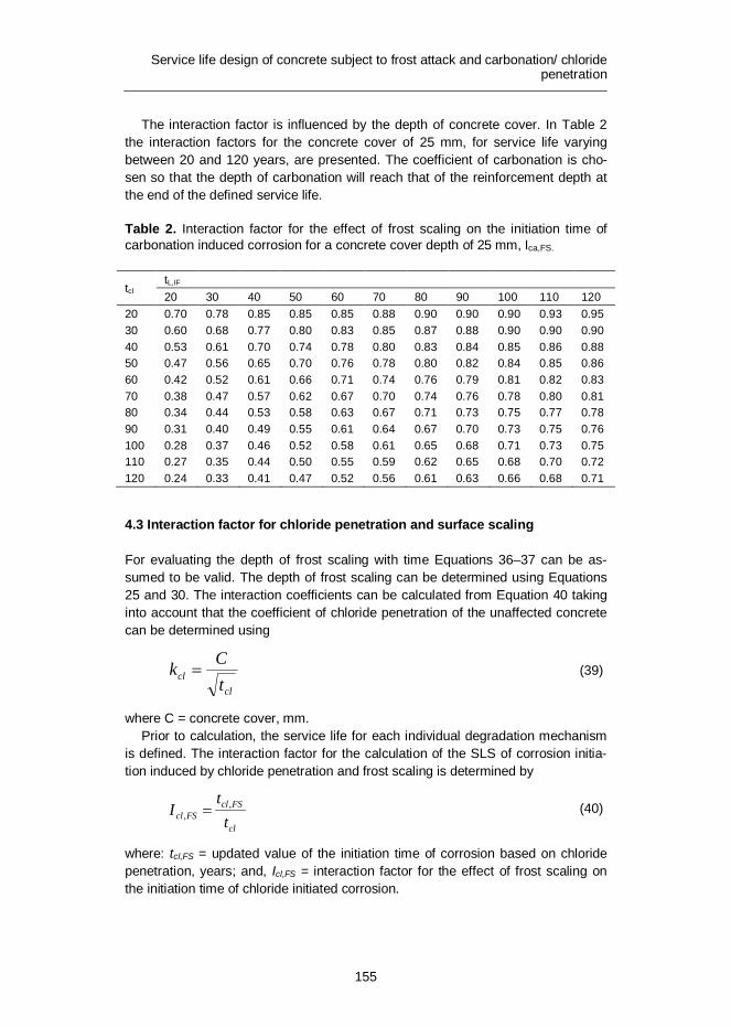
Service life design of concrete subject to frost attack and carbonation/ chloride penetration
155
The interaction factor is influenced by the depth of concrete cover. In Table 2 the interaction factors for the concrete cover of 25 mm, for service life varying between 20 and 120 years, are presented. The coefficient of carbonation is cho-sen so that the depth of carbonation will reach that of the reinforcement depth at the end of the defined service life.
Table 2. Interaction factor for the effect of frost scaling on the initiation time of carbonation induced corrosion for a concrete cover depth of 25 mm, Ica,FS.
tcl tL,IF 20 30 40 50 60 70 80 90 100 110 120
20 0.70 0.78 0.85 0.85 0.85 0.88 0.90 0.90 0.90 0.93 0.95 30 0.60 0.68 0.77 0.80 0.83 0.85 0.87 0.88 0.90 0.90 0.90 40 0.53 0.61 0.70 0.74 0.78 0.80 0.83 0.84 0.85 0.86 0.88 50 0.47 0.56 0.65 0.70 0.76 0.78 0.80 0.82 0.84 0.85 0.86 60 0.42 0.52 0.61 0.66 0.71 0.74 0.76 0.79 0.81 0.82 0.83 70 0.38 0.47 0.57 0.62 0.67 0.70 0.74 0.76 0.78 0.80 0.81 80 0.34 0.44 0.53 0.58 0.63 0.67 0.71 0.73 0.75 0.77 0.78 90 0.31 0.40 0.49 0.55 0.61 0.64 0.67 0.70 0.73 0.75 0.76 100 0.28 0.37 0.46 0.52 0.58 0.61 0.65 0.68 0.71 0.73 0.75 110 0.27 0.35 0.44 0.50 0.55 0.59 0.62 0.65 0.68 0.70 0.72 120 0.24 0.33 0.41 0.47 0.52 0.56 0.61 0.63 0.66 0.68 0.71
4.3 Interaction factor for chloride penetration and surface scaling
For evaluating the depth of frost scaling with time Equations 36–37 can be as-sumed to be valid. The depth of frost scaling can be determined using Equations 25 and 30. The interaction coefficients can be calculated from Equation 40 taking into account that the coefficient of chloride penetration of the unaffected concrete can be determined using
clcl t
Ck = (39)
where C = concrete cover, mm. Prior to calculation, the service life for each individual degradation mechanism
is defined. The interaction factor for the calculation of the SLS of corrosion initia-tion induced by chloride penetration and frost scaling is determined by
cl
FSclFScl t
tI ,
, = (40)
where: tcl,FS = updated value of the initiation time of corrosion based on chloride penetration, years; and, Icl,FS = interaction factor for the effect of frost scaling on the initiation time of chloride initiated corrosion.

Service life design of concrete subject to frost attack and carbonation/ chloride penetration
156
The interaction factor is influenced by the depth of concrete cover. In Table 3 the interaction factors for the concrete cover of 50 mm, for service life varying between 20 and 120 years, are presented.
Table 3. Interaction factor for the effect of frost scaling on the initiation time of chloride induced corrosion for a concrete cover depth of 50 mm, Icl,FS.
tcl tL,FS 20 30 40 50 60 70 80 90 100 110 120
20 0.85 0.88 0.90 0.93 0.95 0.95 0.95 0.95 0.95 0.95 0.95 30 0.77 0.82 0.87 0.88 0.90 0.92 0.93 0.93 0.93 0.93 0.93 40 0.70 0.76 0.83 0.85 0.88 0.89 0.90 0.91 0.93 0.93 0.93 50 0.65 0.72 0.80 0.83 0.86 0.88 0.90 0.91 0.92 0.93 0.94 60 0.61 0.69 0.76 0.80 0.83 0.86 0.88 0.89 0.90 0.91 0.92 70 0.57 0.65 0.74 0.78 0.81 0.83 0.86 0.87 0.88 0.89 0.90 80 0.53 0.62 0.71 0.75 0.78 0.81 0.84 0.85 0.86 0.87 0.89 90 0.49 0.58 0.67 0.72 0.76 0.79 0.82 0.84 0.85 0.87 0.88 100 0.46 0.56 0.65 0.70 0.75 0.77 0.80 0.81 0.83 0.84 0.86 110 0.44 0.53 0.62 0.67 0.72 0.75 0.78 0.80 0.82 0.83 0.84 120 0.41 0.51 0.61 0.66 0.71 0.74 0.76 0.79 0.81 0.82 0.83
Table 4. Interaction factor for the effect of internal cracking on the initiation time of chloride induced corrosion, Icl,IF.
tcl tL,IF 20 30 40 50 60 70 80 90 100 110 120
20 0.90 0.93 0.95 0.95 0.95 0.95 0.95 0.95 0.95 0.95 0.95 30 0.86 0.88 0.90 0.92 0.93 0.93 0.93 0.95 0.96 0.96 0.96 40 0.82 0.86 0.90 0.91 0.92 0.92 0.92 0.94 0.95 0.95 0.95 50 0.81 0.85 0.89 0.90 0.91 0.92 0.93 0.94 0.95 0.95 0.95 60 0.79 0.84 0.88 0.90 0.91 0.92 0.93 0.94 0.94 0.94 0.94 70 0.76 0.81 0.85 0.87 0.89 0.90 0.91 0.92 0.92 0.93 0.94 80 0.74 0.79 0.84 0.86 0.88 0.90 0.91 0.92 0.92 0.93 0.93 90 0.73 0.78 0.83 0.85 0.87 0.88 0.89 0.90 0.91 0.92 0.93 100 0.71 0.76 0.81 0.83 0.85 0.87 0.88 0.89 0.90 0.91 0.91 110 0.69 0.74 0.79 0.82 0.85 0.87 0.88 0.89 0.89 0.90 0.91 120 0.68 0.73 0.78 0.81 0.84 0.86 0.87 0.88 0.89 0.90 0.90

Service life design of concrete subject to frost attack and carbonation/ chloride penetration
157
4.4 Interaction factor for chloride penetration and internal cracking
By inserting Equation 20 into Equation 14 the following relationship was obtained:
÷÷
ø
ö
çç
è
æ
÷÷ø
öççè
æ×+×=
93.0
,, 11.01
IFLclIFcl t
tkk (41)
Considering that the predicted initiation time of corrosion without the effect of frost attack is tcl the coefficient of chloride penetration and the depth of chloride pene-tration (of the unaffected concrete) can be determined as follows:
clcl t
Ck = (42)
where tcl = original predicted initiation time of corrosion with respect to chloride penetration, and, C = concrete cover, mm.
Analogically with the case of carbonation, the interaction coefficients can now be determined as a function of tcl and tL,IF. The results are presented in Ta-ble 4.The initiation time of corrosion can be updated using the values presented in Table 4 as follows:
clIFclIFcl tIt ×= ,, (43)
Where tcl,IF = is the updated value of the initiation time of corrosion based on chlo-ride penetration and interacted by internal frost attack, years, and, Icl,IF = interac-tion factor for the effect of internal frost attack on the initiation time of chloride initiated corrosion.
5. Conclusions
Models for concrete performance and service life assessment are presented for the combined degradation mechanism of frost attack and carbonation/chloride penetration. The models presented are based on a combination of both analytical and empirical expressions. The empirical models are based on laboratory testing of concrete specimens and the relationship between the performance indicators for each degradation mechanism.
These models are based on a limited amount of laboratory testing, i.e., for two cement types and water/binder ratios varying between 0.42 and 0.65. In addition, it is assumed that the durability performance of concrete does not vary with time (constant diffusion coefficient), therefore caution is recommended in analysing and using results.
The determination of the interaction factor shows that frost attack clearly has an effect on the rate of carbonation/chloride penetration. Note that the effect of frost scaling on the rate of carbonation/chloride penetration was not verified with in situ

Service life design of concrete subject to frost attack and carbonation/ chloride penetration
158
data. This remains as one requirement to be fulfilled in the future. As a result, service life design and assessment should take into account the combined effect degradation mechanism.
It is expected that, if frost attack is rapid, it is usually the dominating degrada-tion mechanism. If frost attack proceeds slowly, reinforcement corrosion due to carbonation/chloride penetration becomes dominant, and the interaction effects should be considered in the service life design of reinforced concrete structures.
References
1. Kuosa, H. 2011. Concrete durability field testing. Field and laboratory results 2007–2010. In DuraInt Project.VTT. Research Report VTT-R-00481-11. 93.
2. Leivo, M., Sistonen, E., Al-Neshawy, F., Piironen, J., Kuosa, H., Holt, E. and Nordqvist, C. 2011. Effect of interacted deterioration parameters on ser-vice life of concrete structures in cold environments. Laboratory results 2009–2010. In DuraInt Project.VTT. Research Report VTT-R-04799-11.
3. Vesikari, E. and Ferreira, R.M. 2011. Frost deterioration process and interaction with carbonation and chloride penetration. In DuraInt Project. VTT. Research Report VTT-R-02782-11. 45.
4. Puatatsananon, W. and Saouma, V.E. 2005. Nonlinear coupling of carbonation and chloride diffusion in concrete. J Mat Civil Engineering 17(3), pp. 264–275.
5. Ožbolt, J., Balabanić, G., Periškić, G. and Kušter, M. 2010. Modelling the effect of damage on transport processes in concrete. Const Building Mat. 24(9), pp. 1638–1648.
6. Meijers, S., Bijen, J., de Borst, R. and Fraaij, A. 2005. Computational results of a model for chloride ingress in concrete including convection, drying-wetting cycles and carbonation. Mat Struct. 38(2), pp. 145–54.
7. Maekawa, K., Ishida, T. and Kishi, T. 2008. Multi-scale modeling of structural concrete. CRC Press. P. 672.
8. Bertolini, L., Elsener, B., Pedeferri, P. and Polder R. 2005. Corrosion of steel in concrete: Prevention, diagnosis, repair. Wiley-VCH Verlag GmbH. P. 409.
9. Reddy, B., Glass, G.K., Lim, P.J. and Buenfeld, N.R. 2002. On the corrosion risk presented by chloride bound in concrete. Cement and Concrete Composites 24(1), pp. 1–5.

Service life design of concrete subject to frost attack and carbonation/ chloride penetration
159
10. Alonso, C., Andrade, C., Castellote, M. and Castro, P. 2000. Chloride threshold values to depassivate reinforcing bars embedded in a standardized OPC mortar. Cem. Concr. Res. 30, pp. 1047–1055.
11. Fagerlund, G. 1977. The international cooperative test of the critical degree of saturation method of assessing the freeze/thaw resistance of concrete. Mater. Constr. 10(58), pp. 230–251.
12. Scherer, G.W. 1999. Crystallization in pores. Cem. Concr. Res. 29, pp. 1347–1358.
13. Scherer, G.W. and J.J. Valenza. 2005. Mechanisms of frost damage. In: J. Skalny and F. Young (Eds.). Materials science of concrete. Vol. VII. American Ceramic Society. Pp. 209–246.
14. Powers, T.C. 1945. A working hypothesis for further studies of frost resistance of concrete. PCA-Bulletin 5.
15. Powers, T.C. and Helmuth, R.A. 1953. Proceedings of the Highway Research Board 32. 285 p.
16. Kukko, H. 1992. Frost effects on the microstructure of high strength concrete, and methods for their analysis. Espoo, Technical Research Centre of Finland. VTT Publications 126. 133 p.
17. Kukko, H. 1999. Concrete and its constituents: image analysis in characteriz-ing concrete and its constituents. 7th Euroseminar on Microscopy applied to Building Mat. TNO. Delft. Pp. 521–530.
18. Kukko, H. and Paroll, H. 1993. Round Robin tests on concrete frost resistance. 1st Int. Workshop Resist. of Concrete to Scaling due to Freezing in the Presence of Deicing Salts, CRIB, Laval. Pp. 263–272.
19. Kukko, H. and Tattari, K. 1995. Durability of high strength concrete. VTT Julkaisuja 808. 33 p.
20. Penttala, V.E. 1998. Freezing-induced strains and pressures in wet porous materials and especially in concrete mortars. Advanced in Cement Based Materials 7, pp. 8–19.
21. Fagerlund, G. 1977. The international cooperative test of the critical degree of saturation method of assessing the freeze/thaw resistance of concrete. Mater. Constr. 10(58), pp. 230–251.
Service life design of concrete subject to frost attack and carbonation/ chloride penetration
160
22. Fagerlund, G. 1995. The required air content of concrete. Contribution to the Workshop on “Mass Energy Transfer and Deterioration of Building Com-ponents”, Paris, January 1995.
23. Fagerlund, G. 1994. Predicting the service life of concrete exposed to frost action through modelling of the water absorption process in the air-pore system, Lund IT., Building Materials, TVBM- 7085.
24. Fagerlund, G. 1995. Moisture uptake and service life of concrete exposed to frost. Pro. Int. Conf. on Concrete under Severe Conditions, Sapporo, Japan, Vol. 1, E & FN Spon, Tokyo, Aug. 2–4 1995.
25. Setzer, M. 2001. Micro-ice-lens formation in porous solid 1. J. Colloid Interface Sci. 243(1), pp. 193–201.
26. Setzer, M. 2005. Micro ice lens formation, artificial saturation and damage during freeze thaw attack. Buildings and Structures 6. Wiley-VCH Verlag GmbH & Co.
27. Marchand, J., Sellevold, E.J. and Pigeon, M. 1994. The deicer salt scaling deterioration of concrete – An overview. Am. Concr. Inst. SP 145-1, pp. 1–46.
28. Jacobsen, S. 1995. Scaling and cracking in unsealed freeze/thaw testing of Portland cement and silica fume concretes. Thesis report 1995: 101, NTNU, Trondheim.
29. Valenza, J. and Scherer, G. 2007. A review of salt scaling: I. Phenomenology, Cem.Concr. Res. 37, pp. 1007–1021.
30. Valenza, J. and Scherer, G. 2007. A review of salt scaling: II. Mechanisms, Cem.Concr. Res. 37, pp. 1022–1034.
31. Scherer, G.W. and Valenza, J.J. 2005. Mechanisms of frost damage. In: J. Skalny and F. Young (Eds.). Materials Science of Concrete, Vol. VII. American Ceramic Society. Pp. 209–246.
32. Li, B. 2009. Chloride transport in concrete under frost action – An experi-mental study. Master Thesis. TCH. Göteborg. 156 p.
33. Wang, L. and Ueda, T. 2009.Mesoscopic simulation of chlorides ions diffusion in frost-damaged concrete. Int. J Modelling, Identification and Control. 7–2, pp. 148–154.

Service life design of concrete subject to frost attack and carbonation/ chloride penetration
161
34. Bouteille, S. et al. 2010. Penetration of chlorides in hardened concrete during grost salt cycles. EPJ Web of Conferences, 6, 22017.
35. BY50 – Betoninormit 2004.Suomenbetonitieto Oy. 214 p.
36. ISO 15686-1:2011. 2011. Buildings and constructed assets – Service Life Plan-ning. Part 1: General principles. International Organization for Standards. 52 p.
37. Schieβl, P. 1979. Zur Frage der zulässigen Rissbreite und der erforderlichen Betondeckung in Stahlbetonbau unter besonderer Berücksichtigung der Karbonatisierung des Betons (On the question of allowable crack width and adequate concrete cover in reinforced concrete structures with spe-cial attention to carbonation of concrete). Berlin, DeutscherAusschuss für Stahlbeton, Heft 255. 175 p.
38. Vesikari, E. 2009. Carbonation and chloride penetration in concrete with special objective of service life modelling by the Factor Approach. VTT. Research Report VTT-R-04771-09. 38 p.
39. Hanjari, K.Z., Utgenannt, P. and Lundgren, K. 2011. Experimental study of the material and bond properties of frost-damaged concrete. CemConcr Res. 41(3), pp. 244–54.
40. Bazant, Z.P. 1979. Physical model for steel corrosion in concrete sea struc-tures – application. Journal of the Structural Division ASCE 1979: June, pp. 1155–1165.

Challenges facing innovations in corrosion control for sustainable RC constructions
162
Challenges facing innovations in corrosion control for sustainable RC constructions
Joost Gulikers Ministry of Infrastructure and The Environment, Centre for Infrastructure,
Utrecht, The Netherlands ABSTRACT: For large infrastructure projects of the Dutch Ministry of Infrastructure it is required for the contractor to demonstrate the residual service life of existing infra-structure facilities. As in practice no generally accepted methods exist, Rijkswater-staat Centre for Infrastructure has developed a set of preliminary guidelines which allow for an objective quantification of the actual condition with respect to rein-forcement corrosion induced by carbonation and chloride ingress. This assess-ment of the actual condition at the time of inspection is employed as the starting point for a prediction over time of the condition level which may serve as an input for decision-making regarding preventative and corrective maintenance options.
1. Introduction
The Dutch national infrastructure comprises a wide variety of structures which are all managed by the Ministry of Infrastructure. A significant portion of these struc-tures involves bridges and viaducts. In view of their high economic significance, it is considered a major task to keep these infrastructure facilities in a serviceable and structurally safe condition throughout their full operational service life.
Since several years there is a tendency to allow the contractor more freedom in design and maintenance options by imposing fewer restrictions. On the other hand, more responsibilities and thus risks are shifted towards the contractor. This approach has come into effect in projects using a so-called DBFM (Design, Build, Finance and Maintain) contract, in which the contractor is not only responsible for the design and construction, but in addition also for financing and maintenance during a time period ranging from 20 to 30 years. Within these projects not only new structures are involved but also a considerable number of existing structures within a highway area covering a length of 20 to 40 kilometres. In general, the task is expressed by: The contractor shall demonstrate that for all structures involved within the project a residual service life of X years applies, taking into account all relevant degradation mechanisms.
For the design of new reinforced and prestressed concrete structures it is common to apply a design service life of 80 or 100 years. This implies that for existing concrete structures the contractor shall demonstrate that each structure will present a residual service life equal to 100 or 80 years minus the age of a structure at the start of the contract. However, in the relevant codes no methods for calculation of residual service life regarding durability are addressed. In stead,

Challenges facing innovations in corrosion control for sustainable RC constructions
163
for the design of new concrete structures, it is common to find requirements on cement content, water to cement ratio, cover depth and curing are mentioned. If this so-called deemed-to-satisfy approach is followed in practice, it is assumed that the desired design service life will be achieved without unplanned major maintenance activities. Consequently, it is not made possible to predict the devel-opment of the condition level of a structure or it’s components over time with re-spect to deterioration due to reinforcement corrosion induced by either carbona-tion or chloride ingress. Therefore, a comparison between the actual condition determined at a certain age through results obtained by inspection and the pre-dicted condition level based on as-built information cannot be made. This situation poses several questions on the possibilities to fulfil the requirement to demonstrate a certain residual service life and to specify maintenance activities. To this end Rijkswaterstaat has developed a set of preliminary guidelines, see e.g. Gulikers (2009a and 2009b)
2. Objectives
For condition assessment and prediction of residual service life with respect to reinforcement corrosion an objective and straightforward calculation method will be required. Information obtained from on-site inspections will serve as the major input . The actual condition of a structure at the age of inspection shall present a quantified and representative measure for the occurrence of reinforcement corro-sion induced by either carbonation or chloride ingress of the concrete cover. Therefore, for each structural component a quantifiable condition indicator Z will be defined, with 0.0 < Z < 1.0. The situation Z = 1.0 corresponds to a condition level at the start of the operational service life (without any reinforcement corro-sion) and the situation Z = 0.0 refers to widespread active corrosion (or better depassivation) of the reinforcing steel over the complete structural component. The calculated condition level of an existing concrete component at the age of inspection, tinsp, i.e. Z(tinsp), will serve as the starting point for the prediction of the development of the condition level over time, Zp(t). At the end of the design ser-vice life of a component, t = tdsl, the predicted level Zp(tdsl) will be compared with the threshold level, Zcrit, defined by the principal, i.e. the Ministry of Infrastructure, see Figure 1.
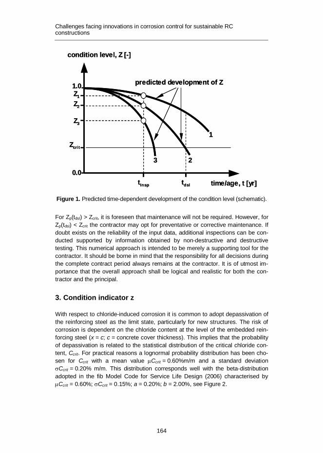
Challenges facing innovations in corrosion control for sustainable RC constructions
164
Figure 1. Predicted time-dependent development of the condition level (schematic).
For Zp(tdsl) > Zcrit, it is foreseen that maintenance will not be required. However, for Zp(tdsl) < Zcrit the contractor may opt for preventative or corrective maintenance. If doubt exists on the reliability of the input data, additional inspections can be con-ducted supported by information obtained by non-destructive and destructive testing. This numerical approach is intended to be merely a supporting tool for the contractor. It should be borne in mind that the responsibility for all decisions during the complete contract period always remains at the contractor. It is of utmost im-portance that the overall approach shall be logical and realistic for both the con-tractor and the principal.
3. Condition indicator z
With respect to chloride-induced corrosion it is common to adopt depassivation of the reinforcing steel as the limit state, particularly for new structures. The risk of corrosion is dependent on the chloride content at the level of the embedded rein-forcing steel (x = c; c = concrete cover thickness). This implies that the probability of depassivation is related to the statistical distribution of the critical chloride con-tent, Ccrit. For practical reasons a lognormal probability distribution has been cho-sen for Ccrit with a mean value mCcrit = 0.60%m/m and a standard deviation sCcrit = 0.20% m/m. This distribution corresponds well with the beta-distribution adopted in the fib Model Code for Service Life Design (2006) characterised by mCcrit = 0.60%; sCcrit = 0.15%; a = 0.20%; b = 2.00%, see Figure 2.
condition level, Z [-]
1.0
Zcrit
time/age, t [yr]tdsl
predicted development of Z
tInsp
Z2
Z3
0.0
Z1
1
23
condition level, Z [-]
1.0
Zcrit
time/age, t [yr]tdsl
predicted development of Z
tInsp
Z2
Z3
0.0
Z1
1
23

Challenges facing innovations in corrosion control for sustainable RC constructions
165
Consequently, the condition indicator Z is defined through:
depPZ -= 1 (1)
where Pdep = probability of reinforcing steel depassivation.
Figure 2. Statistical distribution of the critical chloride content, Ccrit (lognormal).
4. Mathematical model for chloride ingress
In practice the most commonly employed mathematical model for the description of chloride ingress in concrete is based on Fick’s 2nd law of diffusion. For defined boundary and initial conditions this differential equation is analytically solved by using the error-function. This results in a mathematical expression for the predic-tion of chloride ingress as a function of time and distance to the exposed concrete surface, see Figure 3.
( ) ( ) ÷÷ø
öççè
æ
××--=
tDxerfCCCt,xC
aiss 2
(2)
where C(x,t) = chloride content at depth x (exposed concrete surface: x =0 mm) at age t, [%m/m cement], Cs = effective chloride content at the exposed concrete surface (x = 0 mm), [%m/m cement], Ci = initial chloride content), [%m/m cement], x = distance to exposed concrete surface, [mm], Da = apparent chloride diffusion coefficient at time of inspection t, [mm2/yr] and t = age of concrete or structural component, [yr].
0,0
0,2
0,4
0,6
0,8
1,0
0,0 0,2 0,4 0,6 0,8 1,0 1,2chloride content, C [%m/m]
prob
. of d
epas
siva
tion,
Pde
p [-]
mCcrit = 0.60%m/msCcrit = 0.20%m/mlognormal

Challenges facing innovations in corrosion control for sustainable RC constructions
166
Figure 3. Chloride profiles according to Equation 3; Da = 0.5, 2.0 and 8×10-12m2/s (15.8, 63.1, 252.5 mm2/yr), respectively; t = 25yr.
Regarding the chloride content, it should be noted that in practice the total amount of chloride is determined, which includes both free as well as chemically and phys-ically bound chloride. Most often the chloride content is expressed as a percent-age by mass of cement. The initial chloride content reflects the sum of the contam-ination of each ingredient of the fresh concrete mix. The maximal permissible initial chloride content of fresh concrete is limited in the codes depending on the application. Most often the initial chloride content is discarded in the mathematical expressions although Ci can demonstrate significant levels, particularly for old concrete structures for which dune sand or sea dredged aggregates are used.
In the mathematical solution of Fick’s 2nd law of diffusion it is assumed that the effective chloride content at the exposed concrete surface, Cs, remains constant over time. However, in practice this situation will be achieved for exposure periods in excess of 10 years. In the near- surface layer chloride transport is primarily determined by capillary suction, whereas diffusion is the major transport mecha-nism at greater depths. Consequently, for intermittent exposure to chlorides, e.g. for bridge decks (de-icing salt), Equation 2 can only be applied for depths x > 10 mm. The near-surface layer is subjected to significant variations due to the alternate exposure to splash water followed by evaporation. In the vicinity of de-fects, e.g. cracks or gravel pockets, chlorides can permeate relatively fast and deep in the concrete cover.
Most often, a constant level of the chloride diffusion coefficient is assumed, however analyses of measured chloride profiles from real structures have clearly demonstrated that Da essentially reflects a time-dependent model parameter. The
0
1
2
3
0 20 40 60 80
distance to concrete surface, x [mm]
chlo
ride
cont
ent,
C [%
m/m
] Cs
Ci
Cs = 2.60%m/mCi = 0.25%m/mtinsp = 25yr
8·10-12
2·10-120.5·10-12
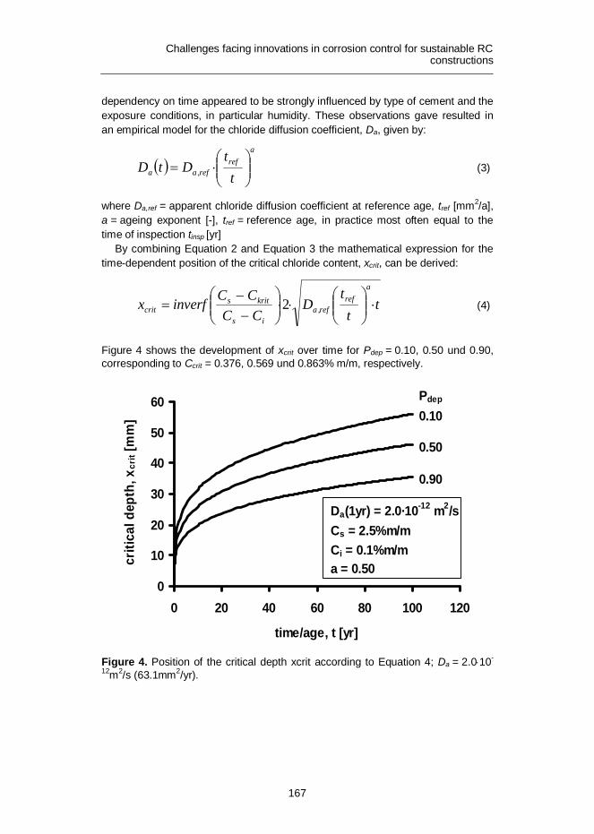
Challenges facing innovations in corrosion control for sustainable RC constructions
167
dependency on time appeared to be strongly influenced by type of cement and the exposure conditions, in particular humidity. These observations gave resulted in an empirical model for the chloride diffusion coefficient, Da, given by:
( )a
refref,aa t
tDtD ÷÷
ø
öççè
æ×= (3)
where Da,ref = apparent chloride diffusion coefficient at reference age, tref [mm2/a], a = ageing exponent [-], tref = reference age, in practice most often equal to the time of inspection tinsp [yr]
By combining Equation 2 and Equation 3 the mathematical expression for the time-dependent position of the critical chloride content, xcrit, can be derived:
tt
tD
CCCCinverfx
aref
ref,ais
kritscrit ×÷÷
ø
öççè
æ××÷÷
ø
öççè
æ--
= 2 (4)
Figure 4 shows the development of xcrit over time for Pdep = 0.10, 0.50 und 0.90, corresponding to Ccrit = 0.376, 0.569 und 0.863% m/m, respectively.
Figure 4. Position of the critical depth xcrit according to Equation 4; Da = 2.0×10-
12m2/s (63.1mm2/yr).
0
10
20
30
40
50
60
0 20 40 60 80 100 120
time/age, t [yr]
criti
cal d
epth
, xcr
it [m
m] 0.10
0.50
0.90
Pdep
Da(1yr) = 2.0·10-12 m2/sCs = 2.5%m/mCi = 0.1%m/ma = 0.50

Challenges facing innovations in corrosion control for sustainable RC constructions
168
5. Practice conditions
The chloride profile measured at an age of the concrete structure tinsp, i.e. the age at which inspections are performed, reflects the influence of the ambient condi-tions regarding exposure to de-cing salt. For the determination of the chloride profile, i.e. the distribution of the chloride content with respect to distance to the exposed concrete surface, normally samples are retrieved from the concrete struc-ture which are analysed in the laboratory by wet chemical analysis. With the usual quantitative techniques for chloride analysis the total chloride content will be de-termined being the sum of the free and bound chloride. Moreover, the chloride content corresponds to the average chloride content of the sampled concrete layer. It is essential that an experienced engineer will be involved to identify the most suitable locations for retrieving chloride samples.
As the measured chloride profiles will be used to quantify the model parameters contained in Equation 1, higher requirements regarding sampling have to intro-duced. In practice this means that concrete cores of at least 50 mm diameter shall be drilled; in view of the high costs associated with the chemical analysis each core will be sawn in sections having a thickness of approximately 10 mm.
Figure 5. Measured chloride contents and continuous chloride profile resulting from regression analysis.
As an example, Figure 5 shows an ideal situation with a chloride profile (10 mm depth intervals) measured at an inspection time tinsp = 25yr as well as the continu-ous chloride profile resulting from regression analysis. The chloride content C1 of the 1st depth interval 0–8 mm representing the near-surface layer, normally does
0
1
2
3
0 20 40 60 80
distance to concrete surface, x [mm]
chlo
ride
cont
ent,
C [%
m/m
]
Cs
Ci
Cs = 2.60%m/mCi = 0.25%m/mDa = 2·10-12m2/stinsp = 25yr
extrapolation
C2C1 C3
C4

Challenges facing innovations in corrosion control for sustainable RC constructions
169
not fit into the mathematical profile as predicted by Equation 1, due to effects resulting from capillary suction, evaporation, and carbonation. Consequently, C1 is usually not taken into account in the regression analysis. The effective chloride content at the exposed concrete surface, Cs, is derived through a mathematical extrapolation of the profile to x = 0. Incidentally, this extrapolation results in unreal-istically high values for Cs. The chloride content determined at greater depths would correspond to the initial chloride content, Ci. For older structures concrete is sometimes contaminated by the use of dune sand or sea-dredged aggregates, exemplified by values for Ci > 0.4%. In practice there is also a risk of systematic errors in the chemical analysis resulting into artificially high initial chloride contents.
In many situations encountered in practice a chloride profile is characterised by 3 chloride contents only. Consequently, the reliability of the interpretation is strongly dependent on the reliability (accuracy) of the measured chloride contents. By using a regression analysis (sum of least squares) each measured chloride profile can be described by the model parameters Cs, Ci, und Da(tinsp) following Equation 1.
6. Probability profile
The calculated continuous chloride profile can be combined with the statistical distri-bution of the critical chloride content, see Figure 2, which results in a so-called de-passivation probability profile. Figure 6 shows the result when the chloride profiles of Figure 1 are used. For tinsp = 25a the probability of depassivation changes from 100% bis 0% within the depth range 20–45 mm. In case the minimum cover depth cmin = 45 mm there will nowhere be a risk for reinforcement corrosion.
Figure 6. Profile of probability of depassivation, Pdep.
0,0
0,2
0,4
0,6
0,8
1,0
0 20 40 60 80
distance to concrete surface, x [mm]
prob
. of d
epas
siva
tion,
Pde
p [-]
100a25a5a

Challenges facing innovations in corrosion control for sustainable RC constructions
170
7. Calculation of the probability of depassivation
Normally, the concrete cover thickness demonstrates a certain variation which can be described in statistical way by an average value mc, a standard deviation sc and a suitable type of probability distribution. A sound statistical interpretation can be achieved by performing extensive on-site measurements. Figure 7 shows an example with mc = 40 mm, sc = 5 and 10 mm, according to a normal distribution. The probability density of the cover depth can be combined with the profile of the depassivation probability as to calculate the probability of depassivation for the steel reinforcement embedded in a specified concrete area. It should be noted that the assumption is made that the measured chloride profile is sufficiently repre-sentative for the specified concrete area. The thus calculated results are presented in Figure 8 as a function of the average cover depth mc for tinsp =25yr.
For t = 25yr and a mean cover depth mc = 45 mm this results into depassivation probabilities Pdep = 0.048 (sc = 5 mm) and 0.137 (sc = 10 mm). Consequently, according to Equation 1 the concrete area considered is characterised by condi-tion levels Z = 0.952 (sc = 5 mm) and Z = 0.863 (sc = 10 mm).
Figure 7. Probability density of the cover depth, c.
0,00
0,05
0,10
0 20 40 60 80concrete cover depth, c [mm]
prob
abili
ty d
ensi
ty, p
[-]
mc = 40mmnormal distribution
sc=5mm
sc=10mm

Challenges facing innovations in corrosion control for sustainable RC constructions
171
Figure 8. Probability of depassivation for tinsp = 25yr as a function of mean cover depth, mc.
8. Prediction of the development of the condition level over time
The starting point for a prediction of the future condition is the condition level Z(tinsp) calculated for the time of inspection. Through application of Equation 2 and Equation 3 it is possible to predict the rate of chloride penetration during the time period t > tinsp. It should be noted that in this prediction the ageing exponent, a, plays a significant role. This is exemplified in Figure 9 for the time-dependent development of the chloride content at a fixed depth x = 55 mm for a wide range of value of the ageing exponent. From the chloride profile measured at inspection time tinsp = 30yr an apparent chloride diffusion coefficient Da(30yr) = 0.5·10-12m2/s is derived. Using this value as a starting point chloride contents C(55 mm) = 0.42 (a = 0.30), 0.38 (a = 0.50) und 0.33 %m/m (a = 0.70) can be predicted for t = 50a. These chloride contents correspond to probabilities of depassivation Pdep = 0.182 (a = 0.30), 0.103 (a = 0.50) und 0.051 (a = 0.70), respectively.
0,0
0,1
0,2
0,3
0,4
0,5
30 40 50 60 70
mean concrete cover depth, mc [mm]
prob
. of d
epas
siva
tion,
Pde
p [-] Cs = 2.5%m/m
Ci = 0.1%m/ma = 0.50t = 25yr
sc=10mm
sc=5mm

Challenges facing innovations in corrosion control for sustainable RC constructions
172
Figure 9. Influence of the ageing exponent, a, on the development of the chloride content at x = 55 m.
The value for the ageing exponent is dependent on cement type and the prevailing exposure conditions, notably humidity. Most often the values reported in literature are obtained from results of relative short term tests on labcrete and these condi-tions are considered hardly representative for long term conditions occurring in practice for realcrete. Internationally, there is no consensus on accepted values for the ageing exponent.
For a specific component of a structure the ageing exponent can be quantified in a reliable way when a series of chloride profiles is available for at least 2 signifi-cantly different times of inspection. The ageing exponent can then be calculated through:
÷÷ø
öççè
æ
÷÷ø
öççè
æ
=
2
1
1
2
ref
ref
ref,a
ref,a
tt
ln
DD
ln
a (5)
Information on the statistical characterisation of the ageing exponent, a, can be found in literature, e.g. fib Model Code for Service life Design (2006). The infor-mation provided in this fib Model Code clearly indicates that a significant variation can be expected, see Figure 10. Full probabilistic calculations have identified that even the standard deviation of the ageing exponent has a pronounced influence
0,0
0,2
0,4
0,6
0,8
0 20 40 60 80 100 120
time/age, t[yr]
chlo
ride
cont
ent,
C [%
m/m
]
a
0.30
0.50
0.70
t insp
Da(30yr) = 0.5·10-12m2/sCs = 2.5%m/mCi = 0.1%m/mCi

Challenges facing innovations in corrosion control for sustainable RC constructions
173
on the computed results. For practice this highlights the care to be exercised in choosing a value for the ageing exponent to be used as an input for (residual) service life prediction.
Figure 10. Probability density of the ageing exponent, a, according to fib Model Code (2006).
9. Practical calculation example
The approach will be exemplified by a 34 year old reinforced concrete beam. For condition assessment each side of this beam is subdivided into 4 surface areas, see Figure 11.
Figure 11. Probability density of the ageing exponent, a, according to fib Model Code (2006).
0
1
2
3
4
0,0 0,2 0,4 0,6 0,8 1,0ageing exponent, a [-]
prob
abili
ty d
ensi
ty, p
(a) [
-]
CEM I
CEM II/B-V
CEM III/B
CementCEM I
CEM III/BCEM II/B-V
m0.300.450.60
s0.120.200.15
8m
A B C D
concrete cores
8m
A B C D
concrete cores

Challenges facing innovations in corrosion control for sustainable RC constructions
174
In each area a 50 mm diameter concrete core is drilled for chloride analysis. In addition, 10 cover depths are measured at locations randomly distributed over an area. Figure 12 shows the results obtained for the chloride profiles and Figure 13 provides the results of the measured cover depths.
The collected data is used to calculate the actual condition level Z(34yr) with respect to chloride-induced reinforcement corrosion. For the complete beam this results into Z(34yr) = 0.95 representing the average value of the 4 concrete sur-faces considered.
For the prediction of the condition level over time, the ageing exponent is as-sumed to be constant with a = 0.50 (CEM III/B-XD3) which allows the calculation of the development of the chloride profiles. The calculated time-dependent devel-opment of Z(t) for each surface area as well as for the complete beam is shown in Figure 14.
Figure 12. Measured chloride contents as a function of depth, x.
0
1
2
3
0 10 20 30 40 50
distance to concrete surface, x [mm]
chlo
ride
cont
ent,
C [%
m/m
]
C
AD
B

Challenges facing innovations in corrosion control for sustainable RC constructions
175
Figure 13. Measured cover depths and characterisation d by statistical parameters.
Thus it can be predicted that an age of 100 years the concrete beam will achieve a condition level Zp(100yr) = 0.78. This outcome can be considered acceptable as for the time being Zcrit(t) = 0.70 is considered the minimum acceptable condition level. Consequently, at t = 34yr no major maintenance needs to be planned by the contractor for the near future. However, from Figure 14 it can be deduced that surface area C shows a significantly worse condition development over time. For this area it would be justified to perform additional non-destructive measurements.
The different performance of area C is also clear in Figure 15. which shows the time-dependent development of the chloride content at the level of the mean cover depth (49.7 mm). For t > 40yr the predicted chloride content will be significantly higher than 0.40% and this indicates a high probability of depassivation.
40
45
50
55
60
A B C Dconcrete surface area
conc
rete
cov
er d
epth
, c [m
m]
mc = 49.2mmsc = 5.7mm
mc = 46.2mmsc = 3.8mm
mc = 49.7mmsc = 5.6mm
mc = 49.9mmsc = 4.3mm

Challenges facing innovations in corrosion control for sustainable RC constructions
176
Figure 14. Development of the condition level over time for the individual concrete surface areas and for the complete beam.
Figure 15. Development of the chloride content over time at the mean cover depth.
10. Concluding remarks
A calculation procedure for quantitative assessment of the condition level for exist-ing concrete structures has been developed. This procedure allows a prediction of
0,0
0,2
0,4
0,6
0,8
1,0
1,2
20 40 60 80 100 120time/age, t [yr]
cond
ition
leve
l, Z
p [-]
BDA
C
beam
0
0,2
0,4
0,6
0,8
20 40 60 80 100 120time/age, t [yr]
chlo
ride
cont
ent,
C [%
m/m
]
C; 49.7mm
A; 49.2mm
B; 46.2mmD; 49.9mm

Challenges facing innovations in corrosion control for sustainable RC constructions
177
the condition level over time taking into account the prevailing exposure conditions and the quality and thickness of the concrete cover. The results may be used by an experienced contractor to plan the nature and extent of maintenance activities at an early stage, and by the asset manager to allocate financial resources.
Until now this procedure has been applied as a pilot in 2 projects. It is conclud-ed that such calculation approach could be useful, however sound engineering judgement will always remain the major basis for condition assessment. Major improvements are suggested which will be implemented in the forthcoming years. In future it is anticipated that modifications resulting from experience obtained in projects will be continually implemented.
References
fib Bulletin 34. 2006. Model Code for Service Life Design. International Federation of Structural Concrete, Lausanne.
Gulikers, J. 2009. Determination of chloride profiles on drilled cores retrieved from existing concrete structures. Utrecht. Rijkswaterstaat. (In Dutch.)
Gulikers, J. 2009. Determination of the condition and residual service life of exist-ing concrete structures with respect to chloride-induced reinforcement corrosion. Utrecht. Rijkswaterstaat. (In Dutch.)


Series title and number VTT Technology 65
Title V International PhD Student Workshop on Durability of Reinforced Concrete From Composition to Service Life Design
Author(s) Rui Miguel Ferreira, Joost Gulikers & Carmen Andrade (Eds.)
Abstract The durability of reinforced concrete structures is more than ever the focus of research. The drive towards a more sustainable society burdens us with the respon-sibility to produce longer lasting structures, with fewer needs for rehabilitation, and using materials with smaller ecological footprints. This is an overwhelming chal-lenge, but one that has been tackled systematically from many different directions.
This workshop, that brought together doctoral students working on the durability of reinforced concrete, reflects the multi-faceted approach with which this challenge is been tackled. Research varies from studying advanced materials for concrete durability to the effects of climate change on deterioration of structures. Other aspects addressed include assessment of repairs for reinforced concrete struc-tures, the performance of concrete with cracking, the service life assessment of existing reinforced concrete structures, and the modelling of chloride ingress and the integrated effect of deterioration mechanism.
ISBN, ISSN ISBN 978-951-38-7899-3 (soft back ed.) ISSN 2242-1211 (soft back ed.) ISBN 978-951-38-7900-6 (URL: http://www.vtt.fi/publications/index.jsp) ISSN 2242-122X (URL: http://www.vtt.fi/publications/index.jsp)
Date December 2012
Language English
Pages 177 p.
Keywords Corrosion, crystal growth, repairs, self-healing, chloride diffusion, Alkali-Silica Reaction, modelling, sustainability, durability, concrete, service life design
Publisher VTT Technical Research Centre of Finland P.O. Box 1000, FI-02044 VTT, Finland, Tel. 020 722 111

VT
T T
EC
HN
OL
OG
Y 6
5
V In
tern
atio
nal P
hD
Stu
den
t Wo
rksh
op
on
Du
rab
ility of R
ein
forc
ed
...ISBN 978-951-38-7899-3 (soft back ed.) ISBN 978-951-38-7900-6 (URL: http://www.vtt.fi/publications/index.jsp)ISSN 2242-1211 (soft back ed.) ISSN 2242-122X (URL: http://www.vtt.fi/publications/index.jsp)
V International PhD Student Workshop on Durability of Reinforced ConcreteFrom Composition to Service Life Design
The durability of reinforced concrete structures is more than ever the focus of research. The drive towards a more sustainable society burdens us with the responsibility to produce longer lasting structures, with fewer needs for rehabilitation, and using materials with smaller ecological footprints. This is an overwhelming challenge, but one that has been tackled systematically from many different directions.
This workshop, that brought together doctoral students working on the durability of reinforced concrete, reflects the multi-faceted approach with which this challenge is been tackled. Research varies from studying advanced materials for concrete durability to the effects of climate change on deterioration of structures. Other aspects addressed include assessment of repairs for reinforced concrete structures, the performance of concrete with cracking, the service life assessment of existing reinforced concrete structures, and the modelling of chloride ingress and the integrated effect of deterioration mechanism.