V 5.0 / V 6.0 DISCONTINUED - Home | Atlas Scientific · · 2017-10-05All commands must be...
15
Dissolved Oxygen Circuit AtlasScientific Biology • Technology V 5.0 / V 6.0 Features • Full range Dissolved Oxygen readings +/- 0.01 • Accuracy within three significant figures (XX.XXX Mg/L) • Temperature dependent, or independent readings • Fresh water/Saltwater/Brackish water readings • Conductivity dependent, or independent readings • Simple calibration • Simple asynchronous serial connectivity (voltage swing 0-VCC) • Single reading, or continuous reading modes • Simple asynchronous serial connectivity with 8 different baud rates • Automatic baud rate detection • Simple instruction set consisting of only 10 commands • Debugging LED's • 2.5V to 5.5V operational voltage • Low power consumption • ROHS compliant 1 Atlas-Scientific.com 4.7 mA at 3.3V in active mode* 4.0 mA at 3.3V in quiescent mode* *LED's off Description Building upon our ever increasing expertise in the field of chemical anal- ysis and robotics, D.O. 5 is our most advanced circuit yet. The Atlas Scientific D.O. 5 is even easier to use than any circuit before with simple calibration, accurate readings, new auto baud rate detection and improved LED debugging capabilities. Copyright © Atlas Scientific LLC All Rights Reserved as of 11/19/14 DISCONTINUED
Transcript of V 5.0 / V 6.0 DISCONTINUED - Home | Atlas Scientific · · 2017-10-05All commands must be...

Dissolved Oxygen Circuit
AtlasScientificBiology • Technology
V 5.0 / V 6.0
Features• Full range Dissolved Oxygen readings +/- 0.01 • Accuracy within three significant figures (XX.XXX Mg/L)• Temperature dependent, or independent readings• Fresh water/Saltwater/Brackish water readings• Conductivity dependent, or independent readings• Simple calibration• Simple asynchronous serial connectivity (voltage swing 0-VCC)• Single reading, or continuous reading modes• Simple asynchronous serial connectivity with 8 different baud rates• Automatic baud rate detection• Simple instruction set consisting of only 10 commands• Debugging LED's• 2.5V to 5.5V operational voltage• Low power consumption• ROHS compliant
1Atlas-Scientific.com
4.7 mA at 3.3V in active mode*4.0 mA at 3.3V in quiescent mode**LED's off
DescriptionBuilding upon our ever increasing expertise in the field of chemical anal-ysis and robotics, D.O. 5 is our most advanced circuit yet. The Atlas Scientific D.O. 5 is even easier to use than any circuit before with simple calibration, accurate readings, new auto baud rate detection and improved LED debugging capabilities.
Copyright © Atlas Scientific LLC All Rights Reserved
as of 11/19/14DISCONTINUED

AtlasScientificBiology • Technology
ContentsSystem Overview ..................................................................Pin Out .................................................................................Absolute Maximum Ratings ..................................................Device operation ..................................................................L1 ......................................................................................... L0 .........................................................................................R ...........................................................................................C ........................................................................................... % ........................................................................................... E ........................................................................................... X ...........................................................................................TT.TT, CCCCC ........................................................................TT.TT,B ..................................................................................TT.TT,S ..................................................................................M ..........................................................................................Z0 .........................................................................................Z(1-8) ...................................................................................I ...........................................................................................Wiring .................................................................................Footprint ............................................................................Warranty .............................................................................
3344666777788999
1010111213
2Atlas-Scientific.com Copyright © Atlas Scientific LLC All Rights Reserved
AtlasScientificBiology • Technology
Atlas-Scientific.com 3
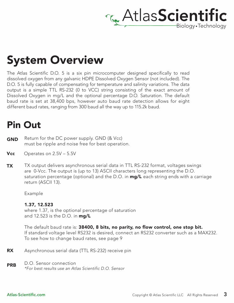
System OverviewThe Atlas Scientific D.O. 5 is a six pin microcomputer designed specifically to read dissolved oxygen from any galvanic HDPE Dissolved Oxygen Sensor (not included). The D.O. 5 is fully capable of compensating for temperature and salinity variations. The data output is a simple TTL RS-232 (0 to VCC) string consisting of the exact amount of Dissolved Oxygen in mg/L and the optional percentage D.O. Saturation. The default baud rate is set at 38,400 bps, however auto baud rate detection allows for eight different baud rates, ranging from 300 baud all the way up to 115.2k baud.
Pin Out
RX
Return for the DC power supply. GND (& Vcc)must be ripple and noise free for best operation.
GND
Vcc Operates on 2.5V – 5.5V
TX output delivers asynchronous serial data in TTL RS-232 format, voltages swingsare 0-Vcc. The output is (up to 13) ASCII characters long representing the D.O. saturation percentage (optional) and the D.O. in mg/L each string ends with a carriagereturn (ASCII 13).
Example
1.37, 12.523where 1.37, is the optional percentage of saturationand 12.523 is the D.O. in mg/L
The default baud rate is: 38400, 8 bits, no parity, no flow control, one stop bit.If standard voltage level RS232 is desired, connect an RS232 converter such as a MAX232.To see how to change baud rates, see page 9
TX
Asynchronous serial data (TTL RS-232) receive pin
PRB D.O. Sensor connection*For best results use an Atlas Scientific D.O. Sensor
Copyright © Atlas Scientific LLC All Rights Reserved

AtlasScientificBiology • Technology
Atlas-Scientific.com 4
Absolute Maximum Ratings*
Device operation
Parameter MIN TYP MAX Units
Storage temperature(D.O. Circuit)
-40 125 C°
1 9925
3.3
C°
2.5 5.5 V
Storage temperature(D.O. probe)
VCC
*Note: Stresses above those listed under “Absolute Maximum Ratings” may cause permanent damage to the device. Exposure to maximum rating conditions for extended periods may affect device reliability
When the D.O. Circuit is first powered up it will immediately begin outputting D.O. Sensor readings Q 650mswhether a D.O. Sensor is connected or not. The data is the detected D.O. in mg/L (+/- 0.01 mg/L) transmitted through the TX pin at a baud rate of 38,400 bps ( 8 data bits, 1 stop bit, no parity, no flow control).The red LED will blink if an unknown command has been transmitted to the D.O Circuit. The D.O. Circuit willrapidly blink red/green if it has no set baud rate (see setting baud rate for more information).
There are a total of 10 different commands that can be given to the D.O. system.All commands must be followed by a carriage return <CR>.Commands are not case sensitive.
A typical D.O. probe takes approximately 2 minutes to fully respond to a change in its environment. A small amount of fluctuation in the readings is normal.
Copyright © Atlas Scientific LLC All Rights Reserved
An Atlas Scientific D.O. Sensor (not included) can operate continuously for approx. 24 months without needing recalibration. The D.O. Sensor (not included)can be fully submerged indefinitely excluding recalibration and cleaning.

Command listQuick reference
Command Function Default state
L1
L0
R
TT.TT, CCCCC
TT.TT,B; TT.TT,S
C
E
X
Enables debugging LEDs
Disables debugging LEDs
Returns a basic D.O. reading. Where the temperature is 20 ° Celsius and the conductivity is 0
Returns a temperature/ conductivity compensatedD.O. reading (conductivity can be 0 if in fresh water)
Returns a temperature/ conductivity compensatedD.O. reading. Where “s” is salt water or “b” is brackish water
Returns continues readings Q 500ms at the temperature /conductivity previously used.
Stops all readings. Enter standby/quiescent mode.
Factory Reset
Enabled
Disabled
Disabled
N/A
Enabled
% Toggles on/off the percentage of D.O. saturation Disabled
N/A
N/A
Z0 Change baud rate 38,400 bps
Z(1-8) Set fixed baud rate Z6 (38,400 bps)
I Instructs the DO Circuit to transmit its version number. N/A
M Calibrates the D.O. N/A
N/AS= 54,000µsB=19,900 µs
AtlasScientificBiology • Technology
Atlas-Scientific.com 5Copyright © Atlas Scientific LLC All Rights Reserved
Atlas-Scientific.com
AtlasScientificBiology • Technology
6
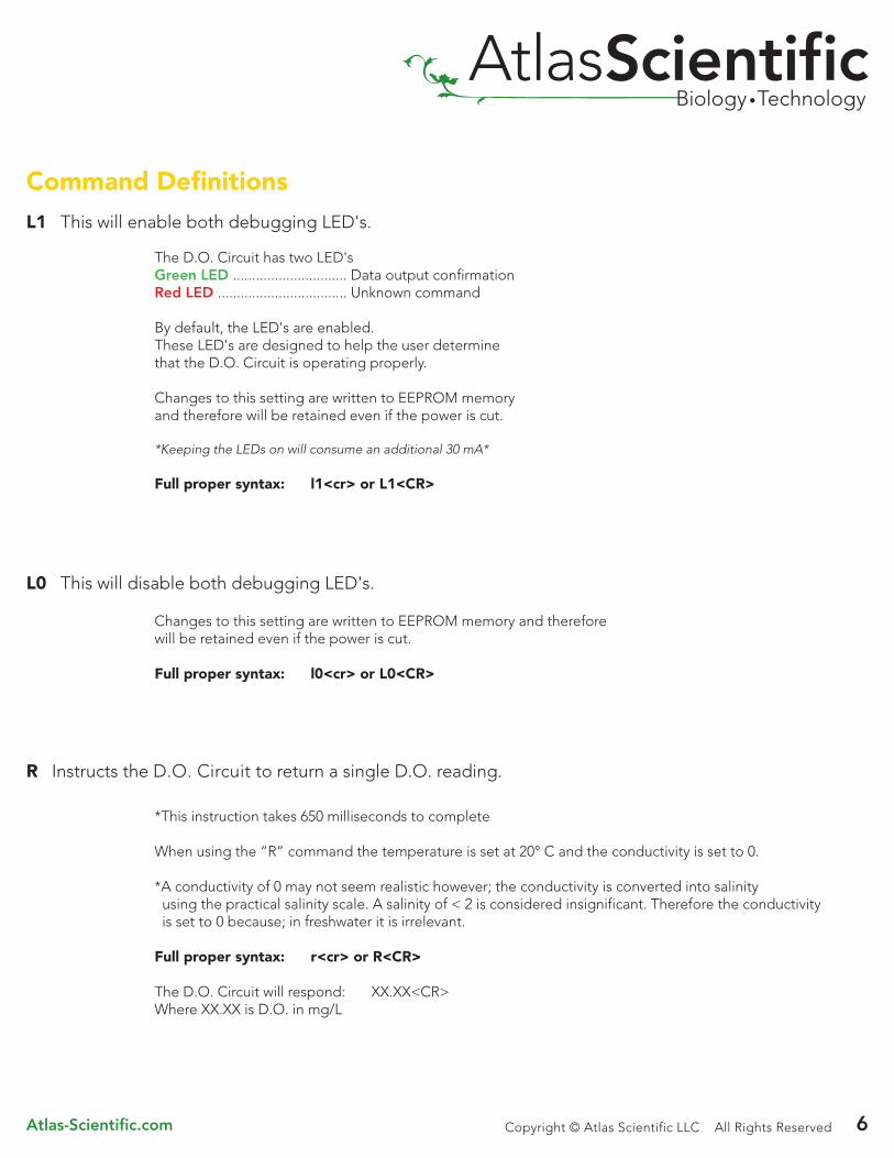
Command DefinitionsL1 This will enable both debugging LED's.
The D.O. Circuit has two LED'sGreen LED .............................. Data output confirmationRed LED .................................. Unknown command
By default, the LED's are enabled.These LED's are designed to help the user determine that the D.O. Circuit is operating properly.
Changes to this setting are written to EEPROM memoryand therefore will be retained even if the power is cut.
*Keeping the LEDs on will consume an additional 30 mA*
Full proper syntax: l1<cr> or L1<CR>
L0 This will disable both debugging LED's.
Changes to this setting are written to EEPROM memory and thereforewill be retained even if the power is cut.
Full proper syntax: l0<cr> or L0<CR>
R Instructs the D.O. Circuit to return a single D.O. reading.
*This instruction takes 650 milliseconds to complete
When using the “R” command the temperature is set at 20° C and the conductivity is set to 0.
*A conductivity of 0 may not seem realistic however; the conductivity is converted into salinity using the practical salinity scale. A salinity of < 2 is considered insignificant. Therefore the conductivity is set to 0 because; in freshwater it is irrelevant.
Full proper syntax: r<cr> or R<CR>
The D.O. Circuit will respond: XX.XX<CR>Where XX.XX is D.O. in mg/L
Copyright © Atlas Scientific LLC All Rights Reserved

Atlas-Scientific.com
AtlasScientificBiology • Technology
7
C Instructs the D.O. Circuit to take continues reading at the parameters previously set
E Instructs the D.O. Circuit to cease continuous mode and enter its standby/quiescent mode.
Delivering this instruction when not in continuous mode will have no effect on the D.O. Circuit
Full proper syntax: e<cr> or E<CR>
The D.O. Circuit will respond by ceasing data transmission.There is no ASCII response to this instruction.
Full proper syntax: %<CR>
% Instructs the D.O. Circuit to toggle on/off the percentage D.O. Saturation.
If the % command is transmitted the output of the D.O. circuit will append the percentage saturationfollowed by a comma. This number will be an integer.
Example
12.523 - Data output with percentage saturation disabled.
1, 12.523 - Data output after “%” command has been sent.
To disable this output, simply send the “%” command again.
Copyright © Atlas Scientific LLC All Rights Reserved
X Instructs the D.O. Circuit to return to its original factory settings.
Transmitting this command will:Reset the measured calibration back to factory defaultReset default temperature back to 20°CSet debugging LED to on.
Full proper syntax: x<CR> or X<CR>
The D.O. Circuit will respond: reset<CR>

Atlas-Scientific.com
AtlasScientificBiology • Technology
8
Instructs the D.O. Circuit to set the temperature and /orconductivity compensation.
This instruction will not produce a response
TT.TT,CCCCCTT.TT,BTT.TT,S
• Temperature is always in Celsius.• Conductivity is always in Microsiemens• “B” is a short hand way of setting the conductivity to that of brackish water: 19,900 µs• “S” is a short hand way of setting the conductivity to that of salt water: 54,000 µs
If you are taking a reading in fresh water simply set the conductivity to zero.
Adding the Microsiemens (the conductivity) will have no positive effect on the readings IN FRESH WATER AND SHOULD BE OMITED. ADDING CONDUCTIVITY IN FRESH WATERMAY LEAD TO INACURATE READINGS.
Example:
Temperature compensated reading in freshwater:19,0<CR>
Else19,1200<CR> Here we take a temperature reading at 19 °C and at a conductivity of 1200 µs.
Or
19,b<CR> Here we take a temperature reading at 19 °C and at a conductivity ofbrackish water 19,900 µs
Or
19,s<CR> (here we take a temperature reading at 19 °C and at a conductivity ofsalt water 54,000 µs
Or
19,80123 <CR> Here we take a temperature reading at 19 °C and at a conductivity of very salty water 80123 µs
*The conductivity can be set as high as 99,999 or as low as 0*The temperature can be set as high as 99 or as low as 0
Copyright © Atlas Scientific LLC All Rights Reserved

Example
Setting baud rate
Transmitting the “Z0<cr>” command will set the D.O. Circuit to auto baud detection mode.The red/green LEDs will rapidly blink, the D.O. Circuit will be waiting to receive the letter “U” (Ascii 85) followed by a <cr> at one of the eight possible baud rates.
(at default baud rate 38.4k bps)Z0<CR> or z0<cr>The D.O. circuit will now begin rapid red/green LED blinking
Change your TX baud rate to your desired setting - i.e. 9600 baud and send the “U” commandU<CR>
The D.O. Circuit will now operate at 9600 baud
The Atlas Scientific D.O. circuit is set to a default rate of 38,400 bps. This baud rare can be changedto one of eight possible different baud rates.
1: 300 baud2: 1200 baud3: 2400 baud4: 9600 baud5: 19.2k baud6: 38.4k baud7: 57.6k baud8: 115.2k baud
Atlas-Scientific.com
AtlasScientificBiology • Technology
9Copyright © Atlas Scientific LLC All Rights Reserved
Z0 Set the auto baud rate
M Instructs the D.O. Circuit to take a measured calibration reading.
A measured calibration should be done the first time the D.O. circuit is used. Dip your probe in water (just to get it wet). Let it sit in the air for 2 minutes. Do not leave it in water, it must calibrate to the oxygenlevel in the surrounding atmosphere. After 2 minutes, transmit the “m” command to calibrate. The greenLED light will blink twice.
The D.O. Circuit will then transmit: “calibration set: nn” Where nn is the atmospheric oxygen partialpressure measured in millivolts. The calibration data will be stored in eeprom and will be used as thebasis for all future readings. This data will not be lost due to power failure.
Full proper syntax: m<cr> or M<CR>

Example
Z(1-8) Set fixed baud rate
(at default baud rate 38.4k bps)
z4<cr> OR Z4<CR>
The D.O. Circuit baud rate has now been changed from 38.4k bps to 9600 bpsThe baud rate can be changed at any time, and as many times as you like.
Sending the Z(1-8) command will instantly set the D.O Circuit to a new baud rate. This new baud rate will be stored to EEPROM and will be retained even if the D.O. Circuit is powered off.
Atlas-Scientific.com
AtlasScientificBiology • Technology
10Copyright © Atlas Scientific LLC All Rights Reserved
* By using the Z0 command the D.O. circuit will enter baud rate detection mode each time it is powered up.If this is not desired simply use the Z(1-8) command
I Instructs the DO Circuit to transmit its version number.
D,V5.0,1/13<CR>
Full proper syntax: i<cr> or I<CR>
A comma separated string will be transmitted that will contain 3 values.
1. The type of device: 2. The firmware version number: 3. The firmware version date:
The D.O. Circuit will respond:
“D” (for D.O.)“V5.0”“1/13” (January / 2013)
REMEMBER ALL TRANSMITIONS ARE TERMANATED WITH A <CR>. THEY ARE NOT TERMANATED WITH A <CR><LF>.MAKE SURE YOUR CODE DOES NOT INADVERTENTLY SEND <CR><LF> AT THE END OF A TRANSMITION.
OK= I<CR> NOT OK = I<CR><LF>

Atlas-Scientific.com
AtlasScientificBiology • Technology
11
* A typical D.O. Sensor should be considered inaccurate if it has been frozen* A typical D.O. Sensor should be considered inaccurate if it has been boiled
We recommend connecting the D.O. circuit as shown.13.9 mm
20 mm
Copyright © Atlas Scientific LLC All Rights Reserved
NC
Do not use this type of connection
Do not use protoboard
AtlasScientificBiology • Technology
Atlas-Scientific.com 12Copyright © Atlas Scientific LLC All Rights Reserved
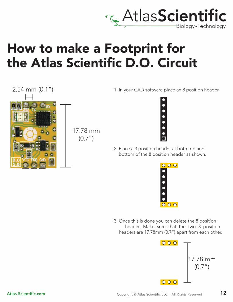
How to make a Footprint forthe Atlas Scientific D.O. Circuit
1. In your CAD software place an 8 position header.
2. Place a 3 position header at both top and bottom of the 8 position header as shown.
3. Once this is done you can delete the 8 position header. Make sure that the two 3 position headers are 17.78mm (0.7”) apart from each other.
2.54 mm (0.1”)
17.78 mm(0.7”)
17.78 mm(0.7”)

AtlasScientificBiology • Technology
Atlas-Scientific.com 13Copyright © Atlas Scientific LLC All Rights Reserved
Warranty
The debugging phase
Atlas Scientific warranty’s the D.O. Circuit to be free of defect during the debugging phase of device implementation, or 30 days after receiving the D.O. Circuit (which ever comes first).
The debugging phase is defined by Atlas Scientific as the time period when the D.O. Circuit is insert-ed into a bread board or shield and is connected to a microcontroller according to this wiring diagram. Reference this wiring diagram for a connection to USB debugging device, or if a shield is being used, when it is connected to its carrier board.
If the D.O. Circuit is being debugged in a bread board, the bread board must be devoid of other components. If the D.O. Circuit is being connected to a microcontroller, the microcontroller must be running code that has been designed to drive the D.O. Circuit exclusively and output the D.O. Circuit’s data as a serial string.
It is important for the embedded systems engineer to keep in mind that the following activities will void the D.O. Circuit’s warranty:
• Soldering any part of the D.O. Circuit• Running any code that does not exclusively drive the D.O. Circuit and output its data in a serial string• Embedding the D.O. Circuit into a custom made device • Removing any potting compound

AtlasScientificBiology • Technology
Atlas-Scientific.com 14Copyright © Atlas Scientific LLC All Rights Reserved
Reasoning behind this warranty Because Atlas Scientific does not sell consumer electronics; once the device has been embedded into a custom made system, Atlas Scientific cannot possibly warranty the D.O. Circuit against the thousands of possible variables that may cause the D.O. Circuit to no longer function properly.
Please keep this in mind:
*Atlas Scientific is simply stating that once the device is being used in your application, Atlas Scientific can no longer take responsibility for the D.O. Circuit continued operation. This is because that would be equivalent to Atlas Scientific taking responsibility over the correct operation of your entire device.
1. All Atlas Scientific devices have been designed to be embedded into a custom made system by you, the embedded systems engineer.
2. All Atlas Scientific devices have been designed to run indefinitely without failure in the field. 3. All Atlas Scientific devices can be soldered into place, however you do so at your own risk.