V-2927 CLOCK CONTROL CARD FOR THE V-2924A · TALKBACK INTERCOM SYSTEM ... • 486 or higher...
13
Issue 2 1 947012 TALKBACK INTERCOM SYSTEM V-2927 CLOCK CONTROL CARD FOR THE V-2924A INTRODUCTION The V-2927 Clock Control Card is an optional plug-in card designed for use with the V-2924A Talkback Intercom System with a V-2928 Option Card. It provides correction and control functions for various impulse and synchronous clocks. The V-2927 also provides a digital output used with the V-DCPI, Digital Clock Protocol Interface, to provide time correction data to Valcom wired and wireless clocks. Programming of various clock types is performed via Windows compatible Programming Tool. The V-2927 requires the use of the V-CIO Clock Interface Board when used with mechanical time clocks. DIMENSIONS/WEIGHT • 5.30”L x 3.00”W x 1.10”D (13.46cm x 7.62cm x 2.79cm) • 0.9 lbs. (0.41 kg) FEATURES • Valcom Digital Output • Two clock ports, independently programmable • 24 mechanical clock types supported (see code list on next page for types) • Manual clock advance (operation dependent on clock types), dial code accessible • Programmable adjustment for daylight savings time (DST) (operation dependent on clock types) • Automatic clock correction after time update • Automatic clock correction after power disruption • Windows Programming Tool MINIMAL SYSTEM REQUIREMENT • V-2924A Control Unit with V-2928 Option Card • V-2927 Clock Control Card • Rev 2.00 Programming Tool • Rev 2.02 Control Unit Software • 486 or higher personal computer with Windows 95, Windows 98 or Windows NT 4.0 operating system, 8 MB RAM, 30 meg free system disk space • V-CIO Interface Board (for impulse clocks) • 1 available DB9 serial communications port
Transcript of V-2927 CLOCK CONTROL CARD FOR THE V-2924A · TALKBACK INTERCOM SYSTEM ... • 486 or higher...
Issue 2
1 947012
TALKBACK INTERCOM SYSTEMV-2927 CLOCK CONTROL CARD
FOR THE V-2924A
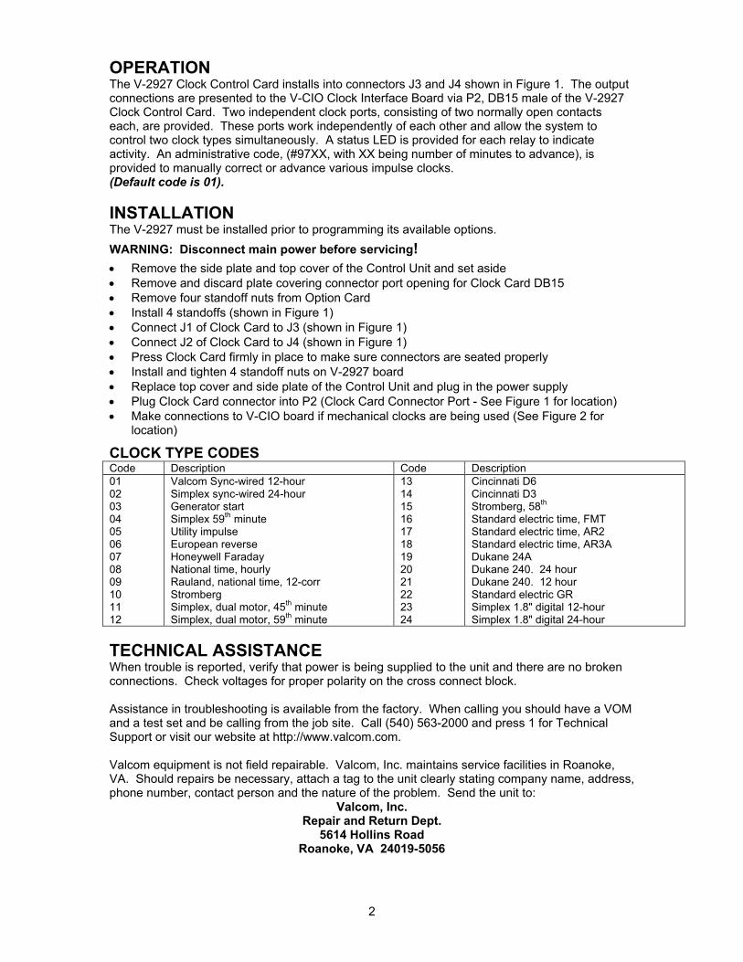
INTRODUCTIONThe V-2927 Clock Control Card is an optional plug-in card designed for use with the V-2924ATalkback Intercom System with a V-2928 Option Card. It provides correction and controlfunctions for various impulse and synchronous clocks. The V-2927 also provides a digital outputused with the V-DCPI, Digital Clock Protocol Interface, to provide time correction data to Valcomwired and wireless clocks. Programming of various clock types is performed via Windowscompatible Programming Tool. The V-2927 requires the use of the V-CIO Clock Interface Boardwhen used with mechanical time clocks.
DIMENSIONS/WEIGHT• 5.30”L x 3.00”W x 1.10”D
(13.46cm x 7.62cm x 2.79cm)• 0.9 lbs. (0.41 kg)
FEATURES• Valcom Digital Output• Two clock ports, independently programmable• 24 mechanical clock types supported (see code list
on next page for types)• Manual clock advance (operation dependent on clock types), dial code accessible• Programmable adjustment for daylight savings time (DST) (operation dependent on clock
types)• Automatic clock correction after time update• Automatic clock correction after power disruption• Windows Programming Tool
MINIMAL SYSTEM REQUIREMENT• V-2924A Control Unit with V-2928 Option Card• V-2927 Clock Control Card• Rev 2.00 Programming Tool• Rev 2.02 Control Unit Software• 486 or higher personal computer with Windows 95, Windows 98 or Windows NT 4.0
operating system, 8 MB RAM, 30 meg free system disk space• V-CIO Interface Board (for impulse clocks)• 1 available DB9 serial communications port
2
OPERATIONThe V-2927 Clock Control Card installs into connectors J3 and J4 shown in Figure 1. The outputconnections are presented to the V-CIO Clock Interface Board via P2, DB15 male of the V-2927Clock Control Card. Two independent clock ports, consisting of two normally open contactseach, are provided. These ports work independently of each other and allow the system tocontrol two clock types simultaneously. A status LED is provided for each relay to indicateactivity. An administrative code, (#97XX, with XX being number of minutes to advance), isprovided to manually correct or advance various impulse clocks.(Default code is 01).
INSTALLATIONThe V-2927 must be installed prior to programming its available options.WARNING: Disconnect main power before servicing!• Remove the side plate and top cover of the Control Unit and set aside• Remove and discard plate covering connector port opening for Clock Card DB15• Remove four standoff nuts from Option Card• Install 4 standoffs (shown in Figure 1)• Connect J1 of Clock Card to J3 (shown in Figure 1)• Connect J2 of Clock Card to J4 (shown in Figure 1)• Press Clock Card firmly in place to make sure connectors are seated properly• Install and tighten 4 standoff nuts on V-2927 board• Replace top cover and side plate of the Control Unit and plug in the power supply• Plug Clock Card connector into P2 (Clock Card Connector Port - See Figure 1 for location)• Make connections to V-CIO board if mechanical clocks are being used (See Figure 2 for
location)
CLOCK TYPE CODESCode Description Code Description010203040506070809101112
Valcom Sync-wired 12-hourSimplex sync-wired 24-hourGenerator startSimplex 59th minuteUtility impulseEuropean reverseHoneywell FaradayNational time, hourlyRauland, national time, 12-corrStrombergSimplex, dual motor, 45th minuteSimplex, dual motor, 59th minute
131415161718192021222324
Cincinnati D6Cincinnati D3Stromberg, 58th
Standard electric time, FMTStandard electric time, AR2Standard electric time, AR3ADukane 24ADukane 240. 24 hourDukane 240. 12 hourStandard electric GRSimplex 1.8" digital 12-hourSimplex 1.8" digital 24-hour
TECHNICAL ASSISTANCEWhen trouble is reported, verify that power is being supplied to the unit and there are no brokenconnections. Check voltages for proper polarity on the cross connect block.
Assistance in troubleshooting is available from the factory. When calling you should have a VOMand a test set and be calling from the job site. Call (540) 563-2000 and press 1 for TechnicalSupport or visit our website at http://www.valcom.com.
Valcom equipment is not field repairable. Valcom, Inc. maintains service facilities in Roanoke,VA. Should repairs be necessary, attach a tag to the unit clearly stating company name, address,phone number, contact person and the nature of the problem. Send the unit to:
Valcom, Inc.Repair and Return Dept.
5614 Hollins RoadRoanoke, VA 24019-5056

3
HIGH VOLTAGE AREADISCONNECT POWERBEFORE SERVICING
J3J4
InstallStandoffs
Here
FIGURE 1 - CLOCK CARD PLACEMENT ON THE CONTROL BOARD
Side View
Top View
P10 P1
RS232 Serial Portfor SMDR (DB9Connector)
PC ProgrammingPort (located onOption Board)
J1 and J2 are located on the underside of the Clock Card
Clock ControlCard Port(located on Clock Card -DB15 Connector)Remove anddiscard plate coveringconnector port
P2
Align J1 on the Clock Card directly over J3.Align J2 on the Clock Card directly over J4.Press V-2927 firmly in place.
Clock Cardpositionsdirectly overthe OptionBoard
4
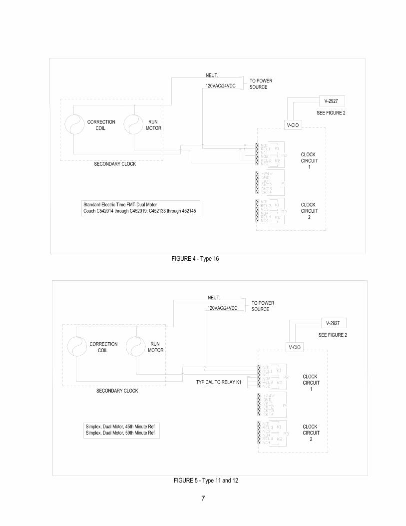
CLOCK TYPE CODESType # Description Figure #
11234456789
10111213141516
1718192021222324
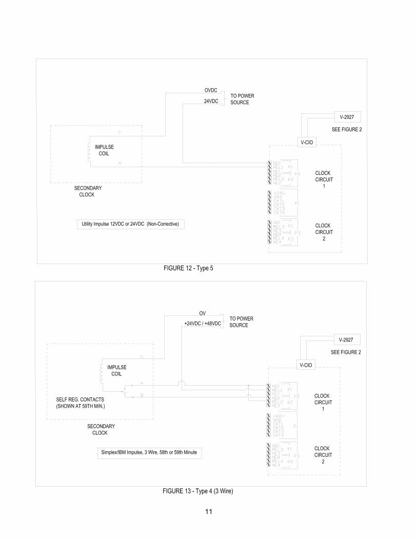
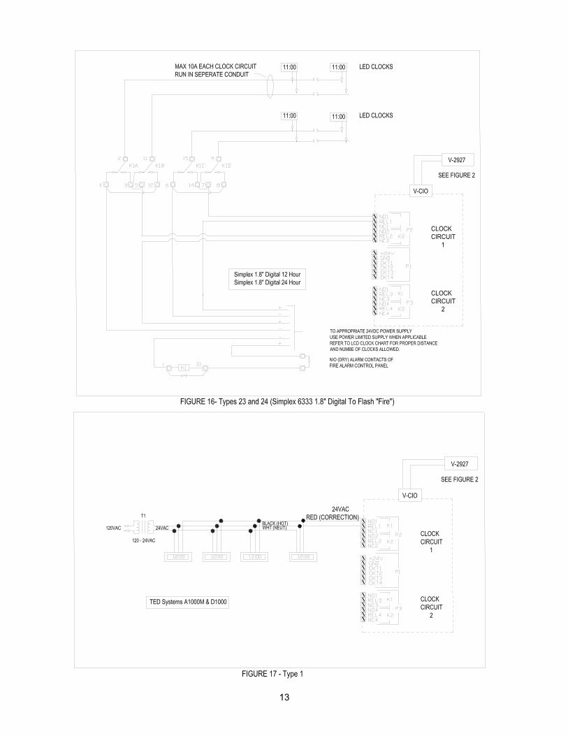
Valcom Sync-wired 12-hourTED Systems A1000M & D1000Simplex/Edwards Sync-wired 24-hourSimplex Generator Start (12 hour & Hourly Correction)Simplex/IBM Impulse, 3 Wire, 58th or 59th MinuteSimplex Impulse, 2 Wire, 59th Minute RefUtility Impulse 12VDC or 24VDC (Non-Corrective)European Duplex Reverse Polarity (24VDC or 48VDC)Honeywell Faraday (1300 Series) / Cincinnati (D Synchronous)National Time HourlyRauland, National Time, 12 Hour CorrectionStromberg (Synchronous, 56th Minute Ref, Electronic)Simplex, dual Motor, 45th Minute RefSimplex, dual Motor, 59th Minute RefCincinnati D6 (Impulse, 12 Hour Correction)Cincinnati D3 (Impulse, 59th Minute Ref)Stromberg (Impulse, 58th Minute Ref)Standard Electric Time FMT-Dual Motor Couch C542014 throughC452019; C452133 through 452145Standard Electric Time, AR2, Impulse, 59th Minute refStandard electric Time, AR3A, Impulse, 60th Minute RefDukane 24A, 24 Hour CorrectionDukane 240, 24 Hour CorrectionDukane 240, 12 Hour CorrectionStandard Electric GR Sync 12 Hour CorrectionSimplex 1.8” digital 12 HourSimplex 1.8” digital 24 Hour
31739
131412113333556664
87
10333
15/1615/16
Simplex 6333 Series LED Load Chart14 AWG 16 AWG 18 AWG 20 AWG 22 AWG 24 AWG
2 4960’ 3109’ 1956’ 1250’ 781’ 481’4 2480’ 1555’ 978’ 625’ 391’ 240’6 1653’ 1036’ 625’ 417’ 260’ 160’8 1240’ 777’ 489’ 313’ 195’ 120’10 992’ 622’ 391’ 250’ 156’ 96’12 827’ 518’ 326’ 208’ 130’ 80’14 709’ 444’ 279’ 179’ 112’ 69’16 620’ 389’ 245’ 156’ 98’ 60’18 551’ 345’ 217’ 139’ 87’ 53’20 496’ 311’ 196’ 125’ 78’ 48’22 451’ 283’ 178’ 114’ 71’ 44’24 413’ 259’ 163’ 104’ 65’ 40’26 382’ 239’ 150’ 96’ 60’ 37’28 354’ 222’ 140’ 89’ 56’ 34’30 331’ 207’ 130’ 83’ 52’ 32’32 310’ 194’ 122’ 78’ 49’ 30’34 292’ 183’ 115’ 74’ 46’ 28’36 276’ 173’ 109’ 69’ 43’ 27’38 261’ 164’ 103’ 66’ 41’ 25’
Num
ber O
f Clo
cks
40 248’ 155’ 98’ 63’ 39’ 24’

5
1
2
3
4
5
6
7
8
9
10
11
12
13
14
15
DB15P2 CLOCKCONTROLS
V-2927
V-CIO
NO1
REL1
NC1
NO2
REL2
NC2
NO3
REL3
NC3
NO4
REL4
NC4
K1
K2
K1
K2
CLOCK CIRCUIT 1P2
P1
CLOCK CIRCUIT 2P3
+24V
GND
CKT1
CKT2
CKT3
CKT4
DIGITAL OUT+
DIGITAL OUT-
GND
FIGURE 2V-CIO CLOCK INTERFACEBOARD CONNECTIONS
TO V-C6124PPOWERSUPPLY
V-2927 CLOCK CONTROL CONNECTIONSPIN # FUNCTION WIRE COLOR
1 2 3 4 5 6 7 8 9101112131415
NOT USEDNOT USEDDIGITAL OUT+DIGITAL OUT-NOT USEDNOT USEDCLK 1 K1 CCLK 1 K1 N/OCLK 1 K4 CCLK 1 K4 N/OCLK 2 K3 CCLK 2 K3 N/OCLK 1 K2 CCLK 2 K2 N/OGND
BLACKWHITEREDGREENORANGEBLUEWHITE/BLACKRED/BLACKGREEN/BLACKORANGE/BLACKBLUE/BLACKBLACK/WHITERED/WHITEGREEN/WHITEBLUE/WHITE
EACH CLOCK I/O P.C. BOARD CAN SUPPORT 2 CLOCK CIRCUITS: CLK 1 AND CLK 2.EACH CIRCUIT CONSISTS OF TWO RELAYS K1 AND K2: FORM C CONTACTS RATED 10A @ 30VDC/10A @125VAC
WARNING: DO NOT ATTEMPT TO OPERATE CLOCKS DIRECTLY FROM MASTER CLOCK BOARD! CONTACTS OF RELAYS ON MASTER CLOCK BOARD ARE NOT PROTECTED.

6
VALCOM LIMITED WARRANTYValcom, Inc. warrants its products to be free from defects in materials and workmanship under conditions of normal use and servicefor a period of one year from the date of shipment. The obligation under this warranty shall be limited to the replacement, repair orrefund of any such defective device within the warranty period, provided that:
1. inspection by Valcom, Inc. indicates the validity of the claim; 2. the defect is not the result of damage, misuse, or negligence after the original shipment; 3. the product has not been altered in any way or repaired by others and that factory sealed units are unopened
(a service charge plus parts and labor will be applied to units defaced or physically damaged); 4. freight charges for the return of products to Valcom are prepaid; 5. all units 'out of warranty' are subject to a service charge. The service charge will cover minor repairs
(major repairs will be subject to additional charges for parts and labor).This warranty is in lieu of and excludes all other warranties, expressed or implied and in no event shall Valcom, Inc. beliable for any anticipated profits, consequential damage, loss of time or other losses incurred by the buyer in connectionwith the purchase, operation or use of the product.
This warranty specifically excludes damage incurred in shipment. In the event a product is received in damaged condition, thecarrier should be notified immediately. Claims for such damage should be filed with the carrier involved in accordance with theF.O.B. point.
Headquarters:Valcom, Inc.
5614 Hollins RdRoanoke, VA 24019
Phone: (540) 563-2000FAX: (540) 362-9800
7

8

9

10
11

12
13


![arXiv:1608.00292v4 [math.GN] 12 Oct 2016 · 2016-10-13 · We show that the answer is no, ... i2!Ki.! K1 K2 K3 K0 K1 K2 K3 K0! K1 K2 K3 K0 K1 K2 K3 K0 Figure 2. K! K1 K2 K3 K0 K1](https://static.fdocuments.in/doc/165x107/5e779fd8cdc8f45d52235a34/arxiv160800292v4-mathgn-12-oct-2016-2016-10-13-we-show-that-the-answer-is.jpg)