UV LASERS: KEY TOOLS FOR MICROMACHING, BY C. PAUL CHRISTENSEN
4
Reprinted from Medical Device & Diagnostic Industry, January 1995 TECHNOLOGY MANUFACTURING UV Lasers: Key Tools for Micromachining c. Paul Christensen Many components used in modern prod- ucts are getting smaller. Over the last three decades, features in integrated-circuit tech- nology have been reduced in size by ap- proximately two orders of magnitude, and micromotors as small as a human hair have been fabricated using photolithography. A similar phenomenon is occurring in the medical device industry: Implantable de- vices are shrinking to ever smaller dimen- sions; catheters are becoming more complex, filled with miniature wires, fibers, probes, and sensors. As feature sizes fall below one-thousandth of an inch, cutting, drilling, and shaping are no longer possible with mechanical ap- proaches. New materials such as chemical vapor-deposited diamond, exotic ceramics, and some organic polymers are difficult or impossible to process using traditional tech- niques. The increased demand for micro- mechanical structures has created the need for new manufacturing tools and techniques. In many instances, lasers are being used to bring original and useful fabrication capa- bilities to advanced materials processing. BACKGROUND After the laser was invented in the early I 960s, it quickly became integrated into ma- chine tools. Early lasers, such as the carbon dioxide (C0 2 ) and neodymium and yttrium, aluminum, and garnet (Nd:YAG) models, generated output in the infrared (IR) portion of the spectrum. They are well suited to cutting and welding materials such as stain- less steel and ceramic, on parts with rela- tively large feature sizes. However, IR pro- cessing usually results in thermal damage to surrounding material (see Figure I). This limits the ability to work in tight spaces in most materials and makes IR lasers unsuit- able for processing many heat-sensitive polymers. Unlike CO 2 and Nd:YAG lasers, excimer lasers, introduced in the mid-1970s, oper- ate in the ultraviolet (UV) region of the spec- trum. Together with frequency-converted Nd:YAG sources, these UV lasers offer a wide range of material-processing capabil- ities not previously available at other wave- lengths. For example, the hardness of diamond makes the use of traditional me- chanical tools too time-consuming and cost- ly. But since UV radiation is strongly ab- sorbed by the diamond substrate, small excimer lasers can be used in combination with high-resolution imaging and precision motion-control systems to cut through the diamond and to produce structures with smoothly sloping walls and continuous depth relief. ADVANTAGES OF UV In 1982, researchers at IBM's Watson Re- search Center (Yorktown Heights, NY) re- ported that organic polymers could be spon- taneously evaporated or etched away when irradiated with pulsed UV light. I They noted several important characteristics of UV in- teraction with polymers that were different from IR interaction with materials, including lack of thermal damage to the substrate and precise control over the etch depth. The term photoablation was coined to describe ma- terial processing with UV lasers. Both the short wavelength and short pulse duration of UV lasers contribute to the re- duction of thermal damage. Since the short- wavelength UV photons can directly break chemical bonds, UV lasers can often vapor- ize a material with minimal heat transfer to the surrounding substrate. The resulting gas flows away from the surface, and the sub- (a) (b) strate tends to be free from melting, recast, or other evidence of thermal damage. The duration of the UV laser pulse is typ- ically a few tens of nanoseconds. Within this time frame, any residual heat produced in the ablation region during the pulse does not have time to diffuse very far into the sur- rounding area. The combination of short wavelength and -short pulse duration effec- tively isolates the region illuminated by the focused beam, resulting in sharply defined edges and imparting a new degree of preci- sion to the ablation process. Another important characteristic of UV lasers is improved focusability. Since the As feature sizes fall below one-thousandth of an inch, cutting, drilling, and sbaping are no longer possible with mechanical approaches. minimum focal spot size that can be pro- duced by an optic is proportional to wave- length, the use of short UV wavelengths allows smaller spot sizes to be produced. Focal spot sizes on the order of I 11m can be easily achieved with current UV optics. Materials that are transparent to light at other wavelengths often begin to exhibit strong absorption in the UV spectrum. The stronger the UV absorption by a material, the less penetration achieved by the UV wavelength. In many solids, each UV pulse may penetrate the material to a depth of less than 111m. By controlling the number Figure 1_ Examples of 300-llm-diam holes cut in a 75-llm-thick polyimide sheet using different lasers, illustrating the ability of UV lasers to cut precise shapes without damaging surrounding material.- (a) was drilled with a pulsed, Q-switched Nd: fAG laser operating at 1.06 11m; (b) was drilled with a fast, axial-flow C02 laser operating in a pulsed mode; and (c) was drilled with an excimer laser at 248 nm. Photos courtesy Lu- monics Inc. (Kanata, Ontario, Canada)_ Copyright © 1995 Canon Communications, Inc.
-
Upload
michael-adelstein -
Category
Documents
-
view
219 -
download
0
description
any components used in modern products are getting smaller. Over the last three decades, features in integrated-circuit technology have been reduced in size by approximately two orders of magnitude, and micromotors as small as a human hair have been fabricated using photolithography. A similar phenomenon is occurring in the medical device industry: Implantable devices are shrinking to ever smaller dimensions; catheters arc becoming more complex, filled with miniature wires, fibers, probes, and sensors.
Transcript of UV LASERS: KEY TOOLS FOR MICROMACHING, BY C. PAUL CHRISTENSEN

Reprinted from Medical Device & Diagnostic Industry, January 1995 TECHNOLOGY MANUFACTURING
UV Lasers: Key Tools for Micromachining c. Paul Christensen
Many components used in modern products are getting smaller. Over the last three decades, features in integrated-circuit technology have been reduced in size by approximately two orders of magnitude, and micromotors as small as a human hair have been fabricated using photolithography. A similar phenomenon is occurring in the medical device industry: Implantable devices are shrinking to ever smaller dimensions; catheters are becoming more complex, filled with miniature wires, fibers, probes, and sensors.
As feature sizes fall below one-thousandth of an inch, cutting, drilling, and shaping are no longer possible with mechanical approaches. New materials such as chemical vapor-deposited diamond, exotic ceramics, and some organic polymers are difficult or impossible to process using traditional techniques. The increased demand for micromechanical structures has created the need for new manufacturing tools and techniques. In many instances, lasers are being used to bring original and useful fabrication capabilities to advanced materials processing.
BACKGROUND
After the laser was invented in the early I 960s, it quickly became integrated into machine tools. Early lasers, such as the carbon dioxide (C02) and neodymium and yttrium, aluminum, and garnet (Nd:YAG) models, generated output in the infrared (IR) portion of the spectrum. They are well suited to cutting and welding materials such as stainless steel and ceramic, on parts with relatively large feature sizes. However, IR processing usually results in thermal damage to surrounding material (see Figure I). This limits the ability to work in tight spaces in most materials and makes IR lasers unsuitable for processing many heat-sensitive polymers.
Unlike CO2 and Nd:YAG lasers, excimer lasers, introduced in the mid-1970s, operate in the ultraviolet (UV) region of the spectrum. Together with frequency-converted Nd:YAG sources, these UV lasers offer a wide range of material-processing capabilities not previously available at other wave
lengths. For example, the hardness of diamond makes the use of traditional mechanical tools too time-consuming and costly. But since UV radiation is strongly absorbed by the diamond substrate, small excimer lasers can be used in combination with high-resolution imaging and precision motion-control systems to cut through the diamond and to produce structures with smoothly sloping walls and continuous depth relief.
ADVANTAGES OF UV
In 1982, researchers at IBM's Watson Research Center (Yorktown Heights, NY) reported that organic polymers could be spontaneously evaporated or etched away when irradiated with pulsed UV light. I They noted several important characteristics of UV interaction with polymers that were different from IR interaction with materials, including lack of thermal damage to the substrate and precise control over the etch depth. The term photoablation was coined to describe material processing with UV lasers.
Both the short wavelength and short pulse duration of UV lasers contribute to the reduction of thermal damage. Since the shortwavelength UV photons can directly break chemical bonds, UV lasers can often vaporize a material with minimal heat transfer to the surrounding substrate. The resulting gas flows away from the surface, and the sub
(a) (b)
strate tends to be free from melting, recast, or other evidence of thermal damage.
The duration of the UV laser pulse is typically a few tens of nanoseconds. Within this time frame, any residual heat produced in the ablation region during the pulse does not have time to diffuse very far into the surrounding area. The combination of short wavelength and -short pulse duration effectively isolates the region illuminated by the focused beam, resulting in sharply defined edges and imparting a new degree of precision to the ablation process.
Another important characteristic of UV lasers is improved focusability. Since the
As feature sizes fall below one-thousandth of an inch, cutting, drilling, and sbaping are no longer possible with mechanical approaches. minimum focal spot size that can be produced by an optic is proportional to wavelength, the use of short UV wavelengths allows smaller spot sizes to be produced. Focal spot sizes on the order of I 11m can be easily achieved with current UV optics.
Materials that are transparent to light at other wavelengths often begin to exhibit strong absorption in the UV spectrum. The stronger the UV absorption by a material, the less penetration achieved by the UV wavelength. In many solids, each UV pulse may penetrate the material to a depth of less than 111m. By controlling the number
Figure 1_ Examples of 300-llm-diam holes cut in a 75-llm-thick polyimide sheet using different lasers, illustrating the ability of UV lasers to cut precise shapes without damaging surrounding material.- (a) was drilled with a pulsed, Q-switched Nd: fAG laser operating at 1.06 11m; (b) was drilled with a fast, axial-flow C02 laser operating in a pulsed mode; and (c) was drilled with an excimer laser at 248 nm. Photos courtesy Lumonics Inc. (Kanata, Ontario, Canada)_
Copyright © 1995 Canon Communications, Inc.

--
TECHNOLOGY
of laser pulses, precise etch depth can be achieved, enabling applications such as patterning thin coatings on a substrate or producing blind holes.
With the high lateral resolution available at UV wavelengths, fabrication of threedimensional microstructures by laser ablation is also possible. The essence of the fabrication process is variation of the local UV exposure over the work surface. The best results are usually achieved with materials that transform directly to a vapor phase at high temperatures, and in cases when the laser and material parameters are matched to maximize UV absorption (for example, the excimer laser ablation of polyimide or diamond).
Finally, the UV photon can initiate chemical reactions. Processes such as deposition, polymerization, or UV curing can be combined with photoablation to create multistep operations that address complex microfabrication problems. One such application could potentially occur if an area needed to be covered by a protective surface that provided restricted access. In this case, a laser could be used to polymerize a gas or liquid to produce a polymer coating on the substrate surface. Then the laser intensity could be increased to cut a small hole in the newly created coating. In this manner, UV-laser processing can provide the basis for a full set of advanced microfabrication tools .
UY PAmRNING TECHNIQUES
As Figure 2 illustrates, two different approaches can be used for surface patterning with UV lasers: mask projection and direct
Mask Lens Substrate
Mask Projection
Laser
x-v work table
Substrate ~ ""
Lens
Direct Writing
Figure 2. Two types of UV patterning techniques.
writing. Mask projection involves using a high-energy laser to backlight a mask. Some masks are composed of thin metal foil s ; higher-quality masks are composed of thin dielectric film layers. After the laser beam passes through the mask, the optical image is projected through the lens. The lens then focuses the optical image onto the work surface.
Mask projection exposes large surface areas simultaneously, resulting in the rapid
production of fixed patterns. For example, if insulation needed to be 'removed from a large area of a flex circuit, a mask could be used to define the shape of the area needing to be cut away. If a laser beam were then projected through the mask, all the patterned insulation would be ablated. In order to change the pattern, a new mask would have to be generated. Consequently, mask projection is well suited to high-volume production of a fixed shape.
Figure 3. A IOO-/lm-diam hole and 400-/lm-diam slot etched into polyimide tubing using direct writing.
Figure 4. A 300-/lm-diam gear etched into diamond using direct writing with a IO-/lm-diam beam. Photos courtesy Potomac Photonics, Inc. (Lanham, MD).
Laser Pulse
Energy (m}) Wavelength
(nm) Maximum Pulse Rep. Rate (Hz)
Cost ($K)
Waveguide excimer Nd:YAG (hannonics) Miniature excimer Standard excimer
0.D3-0.1 0.1-0.3
1-5 10-1000
248,308,351 355,266 351,308,248, 193 351,308,248, 193
2000 4000
100 500
25 80 20
60-200
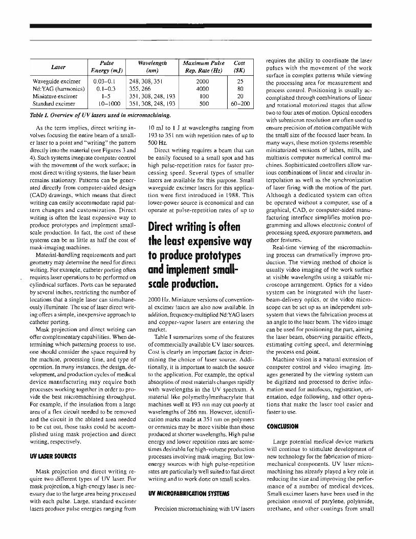
Table l. Overview of UV lasers used in micromachining.
As the term implies, direct writing involves focusing the entire beam of a smaller laser to a point and "writing" the pattern directly into the material (see Figures 3 and 4). Such systems integrate computer control with the movement of the work surface; in most direct writing systems, the laser beam remains stationary. Patterns can be generated directly from computer-aided design (CAD) drawings, which means that direct writing can easily accommodate rapid pattern changes and customization. Direct writing is often the least expensive way to produce prototypes and implement smallscale production. In fact, the cost of these systems can be as little as half the cost of mask-imaging machines.
Material-handling requirements and part geometry may determine the need for direct writing. For example, catheter porting often requires laser operations to be performed on cylindrical surfaces. Ports can be separated by several inches, restricting the number of locations that a single laser can simultaneously illuminate. The use of laser direct writing offers a simple, inexpensive approach to catheter porting.
Mask projection and direct writing can offer complementary capabilities. When determining which patterning process to use, one should consider the space required by the machine, processing time, and type of operation. In many instances, the design, development, and production cycles of medical device manufacturing may require both processes working together in order to provide the best micromachining throughput. For example, if the insulation from a large area of a flex circuit needed to be removed and the circuit in the ablated area needed to be cut out, those tasks could be accomplished using mask projection and direct writing, respectively.
UV WER SOURCES
Mask projection and direct writing require two different types of UV laser. For mask projection, a high-energy laser is necessary due to the large area being processed with each pulse. Large, standard excimer lasers produce pulse energies ranging from
10 mJ to I J at wavelengths ranging from 193 to 351 nm with repetition rates of up to 500 Hz.
Direct writing requires a beam that can be easily focused to a small spot and has high pulse-repetition rates for faster processing speed. Several types of smaller lasers are available for this purpose. Small waveguide excimer lasers for this application were first introduced in 1988. This lower-power source is economical and can operate at pulse-repetition rates of up to
Direct writing is often the least expensive way to produce prototypes and in1plen1ent smallscale production. 2000 Hz. Miniature versions of conventional excimer lasers are also now available. In addition, frequency-multiplied Nd:YAG lasers and copper-vapor lasers are entering the market.
Table I summarizes some of the features of commercially available UV laser sources. Cost is clearly an important factor in determining the choice of laser source. Additionally, it is important to match the source to the application. For example, the optical absorption of most materials changes rapidly with wavelengths in the UV spectrum. A material like polymethylmethacrylate that machines well at 193 nm may cut poorly at wavelengths of 266 nm. However, identification marks made at 351 nm on polymers or ceramics may be more visible than those produced at shorter wavelengths. High pulse energy and lower repetition rates are sometimes desirable for high-volume production processes involving mask imaging. But lowenergy sources with high pulse-repetition rates are particularly well suited to fast direct writing and to work done on small scales.
UV MICROFABRICATION SYSTEMS
Precision micromachining with UV lasers
requires the ability to coordinate the laser pulses with the movement of the work surface in complex patterns while viewing the processing area for measurement and process control. Positioning is usually accomplished through combinations of linear and rotational motorized stages that allow two to four axes of motion. Optical encoders with submicron resolution are often used to ensure precision ofmotion compatible with the small size of the focused laser beam. In many ways, these motion systems resemble miniaturized versions of lathes, mills, and multiaxis computer numerical control machines. Sophisticated controllers allow various combinations of linear and circular interpolation as well as the synchronization of laser firing with the motion of the part. Although a dedicated system can often be operated without a computer, use of a graphical, CAD, or computer-aided manufacturing interface simplifies motion programming and allows electronic control of processing speed, exposure parameters, and other features.
Real-time viewing of the micromachining process can dramatically improve production. The viewing method of choice is usually video imaging of the work surface at visible wavelengths using a suitable microscope arrangement. Optics for a video system can be integrated with the laserbeam-delivery optics, or the video microscope can be set up as an independent subsystem that views the fabrication process at an angle to the laser beam. The video image can be used for positioning the part, aiming the laser beam, observing parasitic effects, estimating cutting speed, and determining the process end point.
Machine vision is a natural extension of computer control and video imaging. Images generated by the viewing system can be digitized and processed to derive information used for autofocus, registration, orientation, edge following, and other operations that make the laser tool easier and faster to use.
CONCLUSION
Large potential medical device markets will continue to stimulate development of new technology for the fabrication of micromechanical components. UV laser micromachining has already played a key role in reducing the size and improving the performance of a number of medical devices. Small excimer lasers have been used in the precision removal of parylene, polyimide, urethane, and other coatings from small

TECHNOLOGY
wires and probes. Miniature flex circuits can be excised and modified with UV laser tools, and precision orifices and apertures are readily formed with focused UV radiation.
UV micromachining has allowed the fabrication of miniature ceramic and diamond components with feature sizes far smaller than those achievable with mechanical tools. Inscription of identification numbers on small metal, plastic, and ceramic components with a UV tool can simplify tracking and quality control. All the tools used in these examples use a UV laser, a system for moving and handling the part, and a viewing system for real-time observation.
As the size of medical devices continues to decrease and new materials become viable, laser shaping and patterning equip
ment will be joined with advanced optical imaging and measurement instruments to produce accurate, easy-to-use microfabrication tools.
REFERENCE
1. Braren B, and Srinivasan R, "Ablative Photodecomposition of Polymers by UV Laser Radiation," in Lasers in Polymer Science and Technology: Applications, vol 3, Fouassier JP, and Rabek JF (eds), Boca Raton, FL, CRC Press, pp 133-177, 1990.
C. Paul Christensen, PhD, is president of Potomac Photonics, Inc. (Lanham, MD), a company that provides the medical device industry with UV laser micromachining equipment and services .•