UV Dose Monitoring That Does Not Require a UVTMonitor · a bUVA Q D S S I UVA ln log 10 0 + ...
8
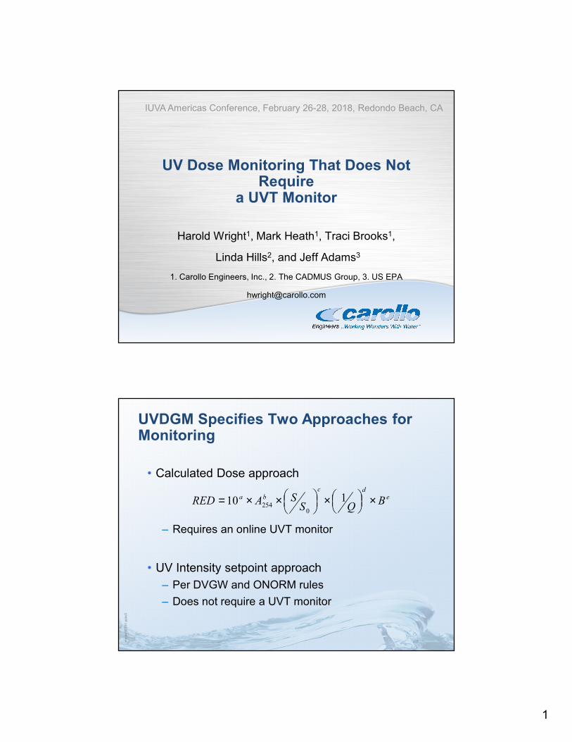
1 UV Dose Monitoring That Does Not Require a UVT Monitor Harold Wright 1 , Mark Heath 1 , Traci Brooks 1 , Linda Hills 2 , and Jeff Adams 3 1. Carollo Engineers, Inc., 2. The CADMUS Group, 3. US EPA [email protected] IUVA Americas Conference, February 26-28, 2018, Redondo Beach, CA mmwd1013i1.pptx/2 UVDGM Specifies Two Approaches for Monitoring • Calculated Dose approach – Requires an online UVT monitor • UV Intensity setpoint approach – Per DVGW and ONORM rules – Does not require a UVT monitor e d c b a B Q S S A RED × × × × = 1 10 0 254
Transcript of UV Dose Monitoring That Does Not Require a UVTMonitor · a bUVA Q D S S I UVA ln log 10 0 + ...
1
UV Dose Monitoring That Does Not Require
a UVT Monitor
Harold Wright1, Mark Heath1, Traci Brooks1,
Linda Hills2, and Jeff Adams3
1. Carollo Engineers, Inc., 2. The CADMUS Group, 3. US EPA
IUVA Americas Conference, February 26-28, 2018, Redondo Beach, CA
mm
wd1013i1
.pptx
/2
UVDGM Specifies Two Approaches for Monitoring
• Calculated Dose approach
– Requires an online UVT monitor
• UV Intensity setpoint approach
– Per DVGW and ONORM rules
– Does not require a UVT monitor
edc
ba BQS
SARED ×
×
××= 110
0254

2
mm
wd1013i1
.pptx
/3
UV Intensity Setpoint Approach – Pros and Cons
Pros Cons
Simple – great for small
systems
Does not report UV dose
Inexpensive validation Specific to one UV dose target,
e.g. 40 mJ/cm2
Does not require an online UVT
monitor
Requires an optimized UV sensor
location
mm
wd1013i1
.pptx
/4
log I vs combined variable S/Q/DL follows single relation at a given UVT
0.00
1.00
2.00
3.00
4.00
5.00
6.00
7.00
0 0.001 0.002 0.003 0.004 0.005
logI
S/Q/DL
70 80 90 95 98 2 cm WL
UV sensor Flow Microbe UV Sensitivity

3
mm
wd1013i1
.pptx
/5
Conservative logI vs S/Q/DL relation can be used for Monitoring
0.00
1.00
2.00
3.00
4.00
5.00
6.00
7.00
0 0.001 0.002 0.003 0.004 0.005
logI
S/Q/DL
70 80 90 95 98 2 cm WL
mm
wd1013i1
.pptx
/6
Efficiency of Approach Depends of UV Sensor-to-Lamp Water Layer Distance
0.00
1.00
2.00
3.00
4.00
5.00
6.00
7.00
0 0.001 0.002 0.003 0.004 0.005
logI
S/Q/DL
70 80 90 95 98 2 cm WL
0.00
1.00
2.00
3.00
4.00
5.00
6.00
7.00
0 0.0005 0.001 0.0015 0.002 0.0025 0.003
logI
S/Q/DL
70 80 90 95 98 3 cm WL
0.00
1.00
2.00
3.00
4.00
5.00
6.00
7.00
0 0.0002 0.0004 0.0006 0.0008 0.001 0.0012 0.0014
logI
S/Q/DL
70 80 90 95 98 5 cm WL
0.00
1.00
2.00
3.00
4.00
5.00
6.00
7.00
0 0.0002 0.0004 0.0006 0.0008 0.001
logI
S/Q/DL
70 80 90 95 98 6 cm WL

4
mm
wd1013i1
.pptx
/7
Optimal UV Sensor Location
• Select location such that conservative UVT is an intermediate UVT
– E.g. Monitoring curve defined at 90% UVT
– 70 and 80% UVT give a higher log inactivation
0.00
1.00
2.00
3.00
4.00
5.00
6.00
7.00
0 0.0002 0.0004 0.0006 0.0008 0.001 0.0012 0.0014
logI
S/Q/DL
70 80 90 95 98 5 cm WL
mm
wd1013i1
.pptx
/8
Fit Conservative Relation to Define Algorithm that Does Not Require UVT
0.00
1.00
2.00
3.00
4.00
5.00
6.00
7.00
0 0.0002 0.0004 0.0006 0.0008 0.001 0.0012 0.0014
logI
S/Q/DL
70 80 90 95 98 5 cm WL
���� = � �
× �
�
���� = � �
× �+ � ×
�
× �
�

5
mm
wd1013i1
.pptx
/9
Can Develop Equations Specific to Pathogen Inactivation Credit
• Equation incorporates DL of target pathogen and validation factor
0
2
4
6
8
10
12
14
16
0.00 0.20 0.40 0.60 0.80 1.00
Cry
pto
Va
lidate
d D
ose
(mJ/c
m2)
S/Q
�,������ = � × �� + � × �
��
mm
wd1013i1
.pptx
/10
Step 1. During Functional Testing, Define UV Sensor Reading Dependence on Water Layer
• Requires adjustable UV sensor port
• Measure UV sensor readings vs. UVTand lamp power setting at three or more water layers

6
mm
wd1013i1
.pptx
/11
Step 2. Conduct Biodosimetry and Develop Equation
( )UVAdc
L
UVAba
DQ
SS
UVAI
ln
010log
×+
×
×××=
mm
wd1013i1
.pptx
/12
Step 3. Use Equation to Predict logI vs. S/Q/DL for at Least 4 UVTs and Identify Optimal UV Sensor Location
0.0
0.5
1.0
1.5
2.0
2.5
3.0
3.5
4.0
4.5
0.00 0.20 0.40 0.60 0.80 1.00 1.20 1.40 1.60 1.80
Lo
g i M
eas
ure
d
S/Q/DL
0.0
0.5
1.0
1.5
2.0
2.5
3.0
3.5
4.0
4.5
0.00 0.05 0.10 0.15 0.20 0.25 0.30 0.35 0.40 0.45
Lo
g i M
eas
ure
d
S/Q/DL
0.0
0.5
1.0
1.5
2.0
2.5
3.0
3.5
4.0
4.5
0.00 0.05 0.10 0.15 0.20 0.25 0.30
Lo
g i M
eas
ure
d
S/Q/DL
2 cm
6 cm
7.5 cm
0.0
0.5
1.0
1.5
2.0
2.5
3.0
3.5
4.0
4.5
0.00 0.05 0.10 0.15 0.20
Lo
g i M
eas
ure
d
S/Q/DL
10 cm

7
mm
wd1013i1
.pptx
/13
Step 4. Define Final Algorithm and Validated Range
• Final Algorithm
– ���� = � ×�
�×��+ � ×
�
���
�
– Or:
– �,������ = � × �� + � ×
���
• Validated Range
– Minimum and maximum flow
– Maximum logI
mm
wd1013i1
.pptx
/14
Benefits of Combined Variable that Does Not Use UVT
• No UVT Monitor
• 4-log adenovirus credit using MS2 phage
• Equation can incorporate DL of target pathogen and validation factor
• Simplifies validated range

8
UV Dose Monitoring That Does Not Require
a UVT Monitor
Harold Wright1, Mark Heath1, Traci Brooks1,
Linda Hills2, and Jeff Adams3
1. Carollo Engineers, Inc., 2. The CADMUS Group, 3. US EPA
IUVA Americas Conference, February 26-28, 2018, Redondo Beach, CA