UTRAN
55
1 U101 UMTS Network Systems Overview UTRAN UTRAN UTRAN
-
Upload
raeefsaleh -
Category
Documents
-
view
277 -
download
7
Transcript of UTRAN

1U101 UMTS Network Systems Overview
UTRAN
UTRANUTRAN

2U101 UMTS Network Systems Overview
Contents and Session AimsContents and Session AimsUTRAN
• This session aims to explain the roles and procedures behind UTRAN
! To describe in detail the entities comprising the UTRAN
! To examine the role of UTRAN in Soft Handover
! To look at Call Admission, Congestion control and Radio Resource Management Algorithms
! To look at how the air interface is affected by power control algorithms
•UTRAN•RNS, RNC and Node-B•Handover in UMTS
•Transmit Diversity•Cell Search and Synchronisation•Power Control
•Admission Control•Load Control•Radio Resource Management

3U101 UMTS Network Systems Overview
UTRANUTRAN• UTRAN is the UMTS Terrestrial Radio Access Network• For any network UTRAN consists of:
! One or more RNSs with their associated RNCs, Node Bs and Cells
• The functions of UTRAN (as described above) are:! System access control! Security and privacy! Handover! Radio resource management and control
UTRAN

4U101 UMTS Network Systems Overview
Radio Network Subsystem (RNS)Radio Network Subsystem (RNS)• A Radio Network Subsystem
consists of:! A single RNC! One or more Node B’s! Cells belonging to Node B’s
• The UMTS equivalent of the GSM BSS
RNC
Node B
Cell
Cell
Cell
Node B
Cell
Cell
Cell
Iur
Iu
Uu
UTRAN

5U101 UMTS Network Systems Overview
Radio Network Controller (RNC)Radio Network Controller (RNC)• Responsible for the use and
integrity of the radio resources within the RNS
• Responsible for the handover decisions that require signalling to the UE
• Provides a combining/splitting function to support macro diversity between different Node Bs
UTRAN
RNC
NodeB
Cell
Cell
Cell
NodeB
Cell
Cell
Cell
Iur
Iu
Uu

6U101 UMTS Network Systems Overview
Node BNode B• Logical node responsible for radio
transmission / reception in one or more cells to/from the UE
• Dual mode Node B can support FDD and TDD mode
• Not necessarily a single site according to the standards
! Most current implementations use a single site
UTRAN
RNC
NodeB
Cell
Cell
Cell
NodeB
Cell
Cell
Cell
Iur
Iu
Uu

7U101 UMTS Network Systems Overview
CellCell• A cell is an area of radio coverage
serviced by one or more carriers
UTRAN
RNC
NodeB
Cell
Cell
Cell
NodeB
Cell
Cell
Cell
Iur
Iu
Uu

8U101 UMTS Network Systems Overview
UTRAN Security and privacyUTRAN Security and privacy• Use of temporary identifier • Encryption for radio channel• Decryption for radio channel
UTRAN

9U101 UMTS Network Systems Overview
Use of Temporary IdentifierUse of Temporary Identifier• There are a number of different types of equipment and user
identifiers used by UMTS• They have been taken directly from GSM to provide some
backwards compatibility! International Mobile Subscriber Identity (IMSI)! Temporary Mobile Subscriber Identity (TMSI)! Temporary Logical Link Identity (TLLI)! Mobile Station ISDN (MSISDN)! International Mobile Station Equipment Identity (IMEI)
UTRAN
10U101 UMTS Network Systems Overview
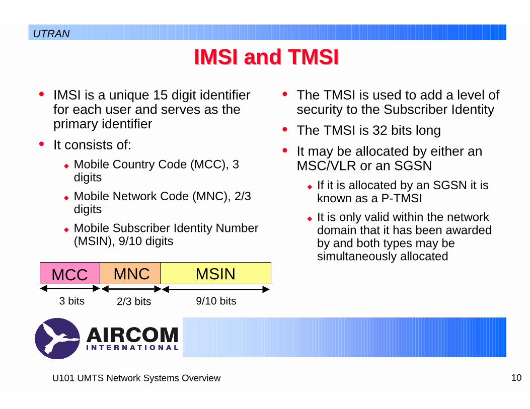
IMSI and TMSIIMSI and TMSI• IMSI is a unique 15 digit identifier
for each user and serves as the primary identifier
• It consists of:! Mobile Country Code (MCC), 3
digits! Mobile Network Code (MNC), 2/3
digits! Mobile Subscriber Identity Number
(MSIN), 9/10 digits
• The TMSI is used to add a level of security to the Subscriber Identity
• The TMSI is 32 bits long• It may be allocated by either an
MSC/VLR or an SGSN! If it is allocated by an SGSN it is
known as a P-TMSI! It is only valid within the network
domain that it has been awarded by and both types may be simultaneously allocated
MCC MNC MSIN3 bits 2/3 bits 9/10 bits
UTRAN

11U101 UMTS Network Systems Overview
UTRAN HandoverUTRAN Handover• Radio environment survey • Handover decision• Macro diversity control• Handover control • Handover execution • Handover completion• SRNS relocation• Inter-system handover
UTRAN
12U101 UMTS Network Systems Overview
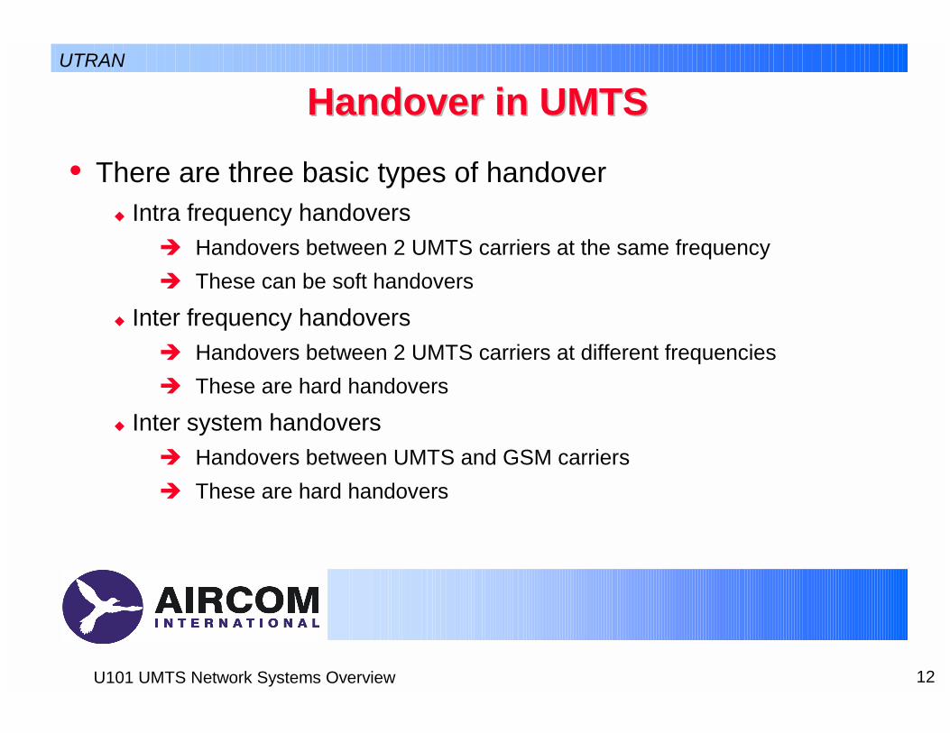
Handover in UMTSHandover in UMTS• There are three basic types of handover
! Intra frequency handovers" Handovers between 2 UMTS carriers at the same frequency" These can be soft handovers
! Inter frequency handovers" Handovers between 2 UMTS carriers at different frequencies" These are hard handovers
! Inter system handovers" Handovers between UMTS and GSM carriers" These are hard handovers
UTRAN
13U101 UMTS Network Systems Overview
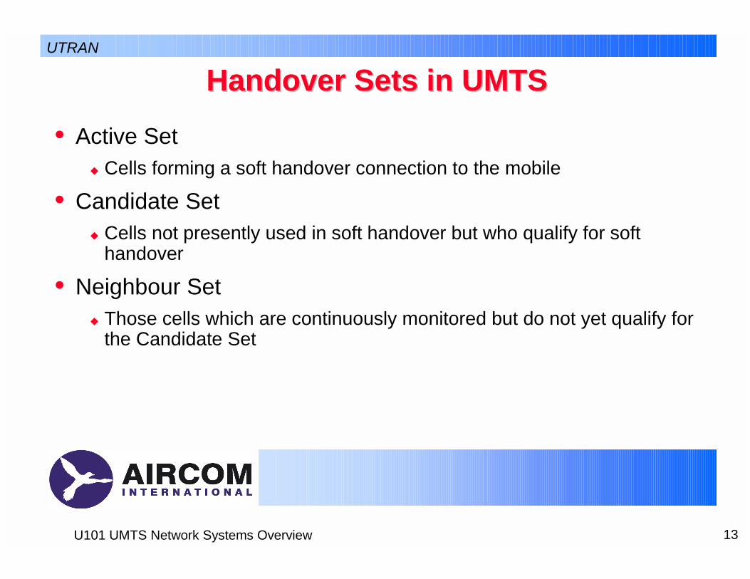
Handover Sets in UMTSHandover Sets in UMTS• Active Set
! Cells forming a soft handover connection to the mobile
• Candidate Set! Cells not presently used in soft handover but who qualify for soft
handover
• Neighbour Set! Those cells which are continuously monitored but do not yet qualify for
the Candidate Set
UTRAN

14U101 UMTS Network Systems Overview
Handover Decisions in UMTSHandover Decisions in UMTS
Pilot Ec/Io
Window_ADD Window_DROP
Direction of Travel
Add Time Delay Drop Time DelayReplace Time Delay
Window_REPLACE
Active set = 1Cell A
= 2Cell A and Cell B
= 2Cell A and Cell C
UTRAN

15U101 UMTS Network Systems Overview
Macrodiversity Macrodiversity between Cells on the Same between Cells on the Same Node BNode B
• If an active set consists of two connections to cells parented to the same Node B then the combining of the two channels occurs at the Node B
• This is known as a softer handover
• This has no transmission implication if cells are collocated.
RNC
Node B
Cell
Cell
Cell
Node B
Cell
Cell
Cell
Iur
Iu
Uu
UTRAN

16U101 UMTS Network Systems Overview
Macrodiversity Macrodiversity between Node B’sbetween Node B’s• If an active set consists of two
connections to cells parented to different Node Bs then the combining of the two channels occurs at the RNC
• This is known as a soft handover
• This doubles the transmission ‘cost’ of the call
RNC
Node B
Cell
Cell
Cell
Node B
Cell
Cell
Cell
Iur
Iu
Uu
UTRAN
17U101 UMTS Network Systems Overview
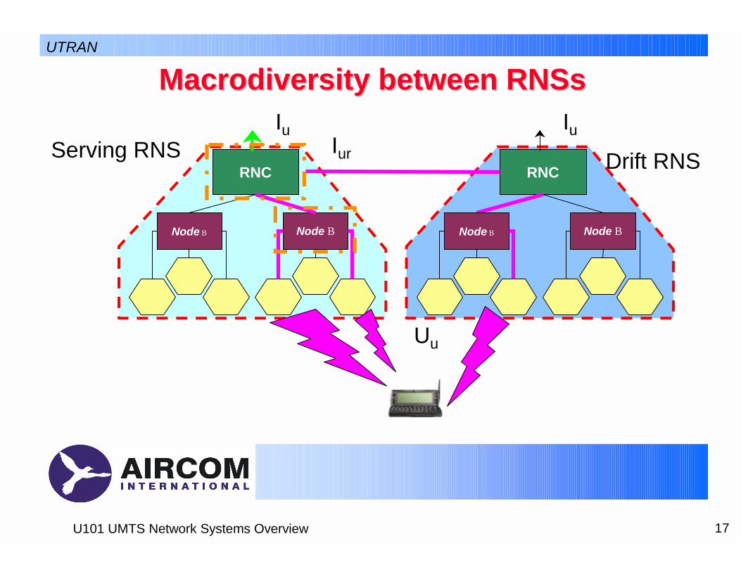
Macrodiversity Macrodiversity between between RNSsRNSs
RNC
Node BNode B
Iu
Uu
RNC
Node BNode B
Iur
IuServing RNS Drift RNS
UTRAN

18U101 UMTS Network Systems Overview
Macrodiversity Macrodiversity between between RNSsRNSs• SRNS provides link between the Core Network and the UE• SRNS also provides the selection function for the different
channels• DRNS relays frames to SRNS through Iur
• As the UE moves then some diversity paths may be dropped and others established
• When the DRNS has more paths than the SRNS the two can exchange function
! Reduces traffic on Iur
UTRAN

19U101 UMTS Network Systems Overview
UTRAN
Site Selection Diversity Transmit Power Site Selection Diversity Transmit Power ControlControl
• Site selection diversity transmit power control (SSDT) is an optional macro diversity method in soft handover mode.
• The UE selects one of the cells from its active set to be ‘primary’, all other cells are classed as ‘non primary’.
• The main objective is to only transmit data on the downlink fromthe primary cell
! Reducing the interference caused by multiple transmissions in a soft handover mode.
• A second objective is to achieve fast site selection without network intervention
! Maintaining the advantage of the soft handover.
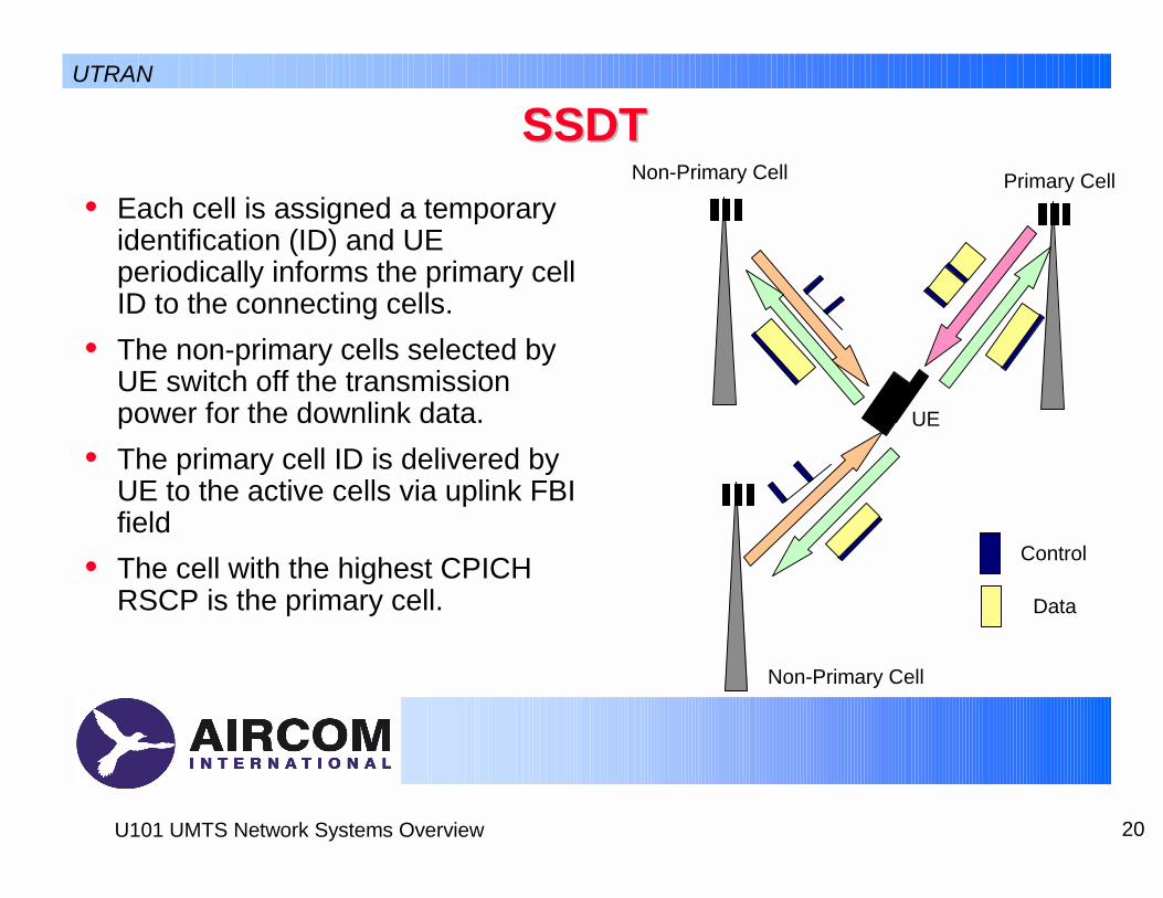
20U101 UMTS Network Systems Overview
UTRAN
SSDTSSDT• Each cell is assigned a temporary
identification (ID) and UE periodically informs the primary cell ID to the connecting cells.
• The non-primary cells selected by UE switch off the transmission power for the downlink data.
• The primary cell ID is delivered by UE to the active cells via uplink FBI field
• The cell with the highest CPICH RSCP is the primary cell.
Primary CellNon-Primary Cell
Non-Primary Cell
UE
Control
Data

21U101 UMTS Network Systems Overview
Hierarchical Cell structuresHierarchical Cell structuresUTRAN
• Cell Layers in UMTS work on a ‘per carrier’ basis
Microcell/Macrocell Scenario Hotspot ScenarioFrequency 1 Frequency 2 Frequencies 1 & 2

22U101 UMTS Network Systems Overview
Hierarchical Cell StructuresHierarchical Cell Structures• Typically operators will be awarded
2 or 3 carriers• If they are awarded 3 carriers it is
then possible to implement HCS by! Using 2 paired carriers for the
macrocell layer! Using 1 paired carrier for the
microcell layer! Using any unpaired spectrum
allocated for the picocell layer using TDD mode
Macro
Micro
Picro
FDD
FDD
TDD
Carrier 1
Carrier 2Carrier 3
Carrier 4
UTRAN
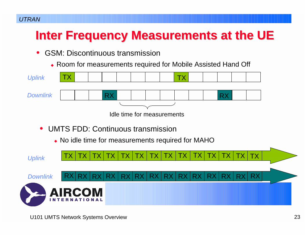
23U101 UMTS Network Systems Overview
Inter Frequency Measurements at the UEInter Frequency Measurements at the UE• GSM: Discontinuous transmission
! Room for measurements required for Mobile Assisted Hand Off
Downlink
TX TXUplink
Idle time for measurements
Downlink
Uplink
UTRAN
RXRX
TX TX TX TX TX TX TX TX TX TX TX TX TX TX
RX RX RX RX RX RX RX RX RXRXRX RX RX RX
• UMTS FDD: Continuous transmission! No idle time for measurements required for MAHO

24U101 UMTS Network Systems Overview
Compressed ModeCompressed Mode• In Compressed Mode a Transmission Gap is created• This allows inter-frequency and inter-system measurements• Probably only required for inter-frequency handover and inter-
mode handover to GSM1800! GSM900 dual mode terminals will probably have separate receivers
UTRAN
Spanning two frames
Spanning a single frame
One Frame, 10ms

25U101 UMTS Network Systems Overview
Compressed ModeCompressed Mode• The Transmission Gap is created
by not transmitting for a number of slots
• Other slots in the frame impacted are then forced to transmit at a higher bit rate, a lower spreading factor and a higher power to maintain the user bit rate
• It is possible to have gaps of 3, 4, 7, 10 and 14 slots
! It is only possible to have gaps of 10 or 14 slots by using two frames
UTRAN
12 13 14 0 1 2 3 4 5 10 11 12 13 14 0 1 2 3 4 5 6 7
4 slot gap

26U101 UMTS Network Systems Overview
Radio Environment SurveyRadio Environment Survey• Received Signal Code Power
! The received code power of the pilot
• Received Signal Strength Indicator! The total in-band signal strength of the carrier
• Ec/Io can be derived from these two items
UTRAN

27U101 UMTS Network Systems Overview
UTRAN System Access ControlUTRAN System Access Control• Admission control• Congestion control • System information broadcasting
UTRAN

28U101 UMTS Network Systems Overview
Admission ControlAdmission Control• If loading is allowed to increase excessively then the coverage
area of the cell reduces below that planned - Admission Control aims to avoid this
• Admission Control functionality is located at the RNC to take the impact on multiple cells into account
• The Admission Control algorithm estimates the impact of adding an additional bearer on both uplink and downlink
! Only if both ‘pass’ is the call admitted
• There are two broad categories of algorithm! Wideband Power Based Admission Control algorithms! Throughput based Admission Control algorithms
UTRAN

29U101 UMTS Network Systems Overview
Wideband Power Based Admission ControlWideband Power Based Admission Control• Uplink Algorithm:
• Downlink Algorithm:
Itotal_old +∆Itotal > Ithreshold
Ptotal_old +∆Ptotal > Pthreshold
Interference
load
Max Planned Noise Rise
Itotal_old
Ithreshold
∆Itotal
∆L
UTRAN

30U101 UMTS Network Systems Overview
Throughput Based Admission ControlThroughput Based Admission Control• Uplink Algorithm
• Downlink Algorithm
ηUL+∆L > ηUL_threshold
ηDL+∆L > ηDL_threshold
UTRAN

31U101 UMTS Network Systems Overview
Congestion (Load) ControlCongestion (Load) Control• Admission control should ensure that the system is not
overloaded• If it is then congestion control returns the system back to the
targeted load• Possible actions include
! Downlink fast load control (deny downlink power up commands)! Uplink fast load control (reduce uplink Eb/No target)! Reduce packet data traffic throughput! Handover to another WCDMA carrier! Handover to GSM! Decrease bit rates for real time users (e.g. AMR bit rates)! Drop calls in a controlled fashion
UTRAN

32U101 UMTS Network Systems Overview
UTRAN Radio Resource ManagementUTRAN Radio Resource Management• Radio bearer set up and release• Reservation and release of physical radio channels • Allocation and release of physical radio channels• Allocation of downlink channelisation codes• Packet data transfer over radio function• Radio channel coding and control • Initial access detection and call handling• Power control
UTRAN

33U101 UMTS Network Systems Overview
Packet Data TransferPacket Data Transfer• Packet Access is controlled in UMTS by a Packet Scheduler
(PS)• The tasks of the PS are to:
! Divide the available air interface capacity between packet users! Decide which transport channels to use for each users packet data! Monitor the packet allocations and the system load
• The PS is typically located at the RNC
UTRAN

34U101 UMTS Network Systems Overview
Common Transport channels for packet Common Transport channels for packet datadata
• The Common Transport channels that can be used for packet access are:
! RACH! FACH
• Low setup time• Link level performance worse than that
of dedicated channels due to lack of closed loop power control and soft handover
• Most Suitable for small individual packets
! SMS! Text only email! Web Page request
Bitrate
Time
User 1
User 2
User 3
User 4
User 5
User 6
User 7
Time based packet scheduling is the mechanism employed when using the common and shared channels
UTRAN

35U101 UMTS Network Systems Overview
Dedicated Transport channels for packet Dedicated Transport channels for packet datadata
• Slow setup time• Link level performance better than
that of common channels due to fast closed loop power control and ability to use soft handover
• Most Suitable for medium or large amounts of data
Bitrate
TimeCode/Transmit based packet scheduling is the mechanism employed when using the dedicated channels
User 1
User 5
User 3User 4
User 2
UTRAN
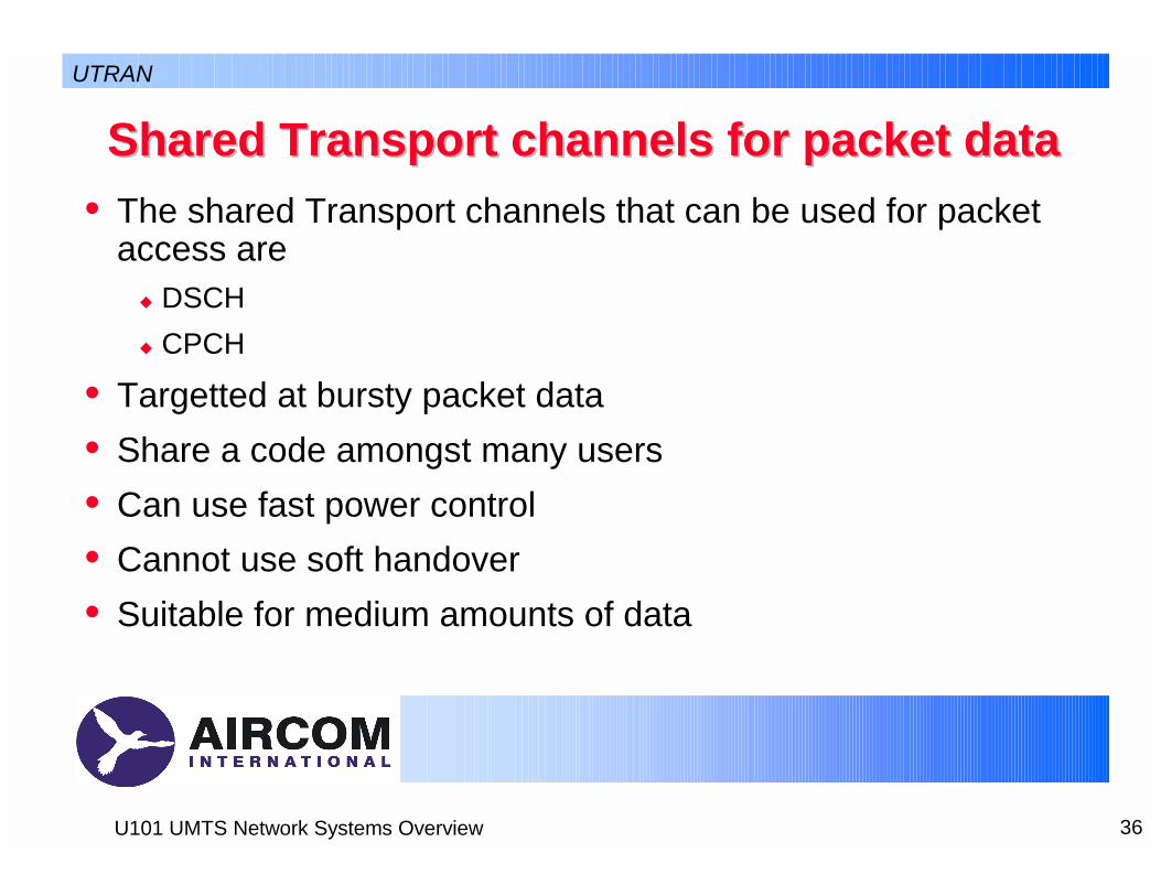
36U101 UMTS Network Systems Overview
Shared Transport channels for packet dataShared Transport channels for packet data• The shared Transport channels that can be used for packet
access are! DSCH! CPCH
• Targetted at bursty packet data• Share a code amongst many users• Can use fast power control• Cannot use soft handover• Suitable for medium amounts of data
UTRAN

37U101 UMTS Network Systems Overview
Packet scheduling in UMTSPacket scheduling in UMTS• In reality the packet scheduler
users a combination of time and code based packet scheduling
• The packet scheduler will work with the admission control algorithm to achieve the target load at a cell
Bitrate
User A
User E
User CUser D
User B
User 1
User 2
User 3
User 4
User 5
User 6
User 7
TimeLoadTarget Load
Non Controllable Real Time Load
Free Capacity
UTRAN

38U101 UMTS Network Systems Overview
Downlink Multiplexing and Channel Coding Downlink Multiplexing and Channel Coding ChainChain
CRC Attachment
Transport Block Concatenation/ Code Block Segmentation
Channel Coding
Rate Matching
Insertion of DTX Indication (fixed Positions only)
First Interleaving (20, 40 or 80ms)
Radio Frame Segmentation
Other Transport Channels Transport Channel
Multiplexing
Insertion of DTX indication (With Flexible
Positions only)
Physical Channel Segmentation
Second Interleaving
(10ms)
Physical Channel Mapping
DPDCH#1
DPDCH#2
DPDCH#n
UTRAN

39U101 UMTS Network Systems Overview
Uplink Multiplexing and Channel Coding Uplink Multiplexing and Channel Coding ChainChain
CRC Attachment
Transport Block Concatenation/ Code Block Segmentation
Channel Coding
Radio Frame Equalisation
Rate Matching
First Interleaving (20, 40 or 80ms)
Radio Frame Segmentation
Other Transport Channels Transport Channel
Multiplexing
Physical Channel Segmentation
Second Interleaving
(10ms)
Physical Channel Mapping
DPDCH#1
DPDCH#2
DPDCH#n
UTRAN

40U101 UMTS Network Systems Overview
CRC AttachmentCRC Attachment• The Cyclic Redundancy Check is used to detect errors in the
transport blocks at the receiving end• There are five lengths of CRC that can be inserted
! 0, 8, 12, 16 and 24 bits
• The more bits the CRC contains the lower the probability of undetected error
UTRAN

41U101 UMTS Network Systems Overview
Code Block Concatenation/SegmentationCode Block Concatenation/Segmentation• The received transport block is either concatenated to other
transport blocks or segmented to allow it to fit into an appropriate block size for the channel coding scheme chosen
• It is typically better to concatenate as:! It reduces the encoder tail bits overhead! It can improve the performance of channel coding to have larger block
sizes
• However over a certain limit segmentation is required to limit complexity
UTRAN

42U101 UMTS Network Systems Overview
Channel CodingChannel Coding• In UTRA two channel coding method are used
! 1/2 and 1/3 rate convolutional coding! 1/3 turbo coding
" 8 state Parallel Concatenated Convolutional Code
UTRAN

43U101 UMTS Network Systems Overview
InterleavingInterleaving• Two different levels of interleaving are used:
! Inter Frame interleaving" When the delay budget allows more than 10ms of interleaving" It is possible to have interleaving over 20, 40 and 80ms time periods
! Intra Frame Interleaving " Over a 10ms time period
UTRAN
44U101 UMTS Network Systems Overview
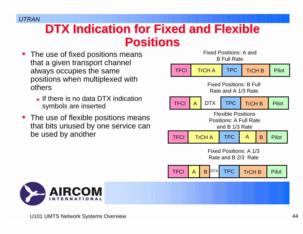
DTX Indication for Fixed and Flexible DTX Indication for Fixed and Flexible PositionsPositions
• The use of fixed positions means that a given transport channel always occupies the same positions when multiplexed with others
! If there is no data DTX indication symbols are inserted
• The use of flexible positions means that bits unused by one service can be used by another
TFCI TrCH A TPC TrCH B Pilot
TFCI A TPC TrCH B PilotDTX
TFCI TrCH A TPC B PilotA
TFCI TPC TrCH B PilotA B DTX
Fixed Positions: A and B Full Rate
Fixed Positions: B Full Rate and A 1/3 Rate
Flexible Positions Positions: A Full Rate
and B 1/3 Rate
Fixed Positions: A 1/3 Rate and B 2/3 Rate
UTRAN
45U101 UMTS Network Systems Overview
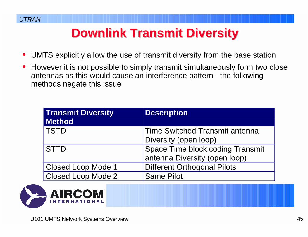
Downlink Transmit DiversityDownlink Transmit Diversity
Transmit DiversityMethod
Description
TSTD Time Switched Transmit antennaDiversity (open loop)
STTD Space Time block coding Transmitantenna Diversity (open loop)
Closed Loop Mode 1 Different Orthogonal PilotsClosed Loop Mode 2 Same Pilot
• UMTS explicitly allow the use of transmit diversity from the base station• However it is not possible to simply transmit simultaneously form two close
antennas as this would cause an interference pattern - the following methods negate this issue
UTRAN

46U101 UMTS Network Systems Overview
Channels Using Downlink Transmit Channels Using Downlink Transmit DiversityDiversity
Physical channeltype
Open loop mode
TSTD STTD
ClosedloopMode
P-CCPCH – X –SCH X – –S-CCPCH – X –DPCH – X XPICH – X –PDSCH – X XAICH – X –CSICH – X –
UTRAN
47U101 UMTS Network Systems Overview
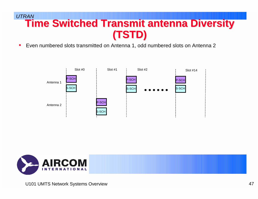
Time Switched Transmit antenna Diversity Time Switched Transmit antenna Diversity (TSTD)(TSTD)
• Even numbered slots transmitted on Antenna 1, odd numbered slots on Antenna 2
Antenna 1
Antenna 2
P-SCH
Slot #0 Slot #1 Slot #14Slot #2
UTRAN
P-SCH
P-SCH P-SCH
S-SCH
S-SCH
S-SCH S-SCH

48U101 UMTS Network Systems Overview
b0 b1 b2 b3
b0 b1 b2 b3
-b2 b3 b0 -b1
Antenna 1
Antenna 2Channel bits
STTD encoded channel bitsfor antenna 1 and antenna 2.
Space Time block coding Transmit antenna Space Time block coding Transmit antenna Diversity (STTD)Diversity (STTD)
• STTD encoding is optional in UTRAN. STTD support is mandatory at the UE• Channel coding, rate matching and interleaving is done as in the non-
diversity mode.• STTD encoding is applied on blocks of 4 consecutive channel bits• The bit bi is real valued {0} for DTX bits and {1, -1} for all other channel bits.
UTRAN
49U101 UMTS Network Systems Overview
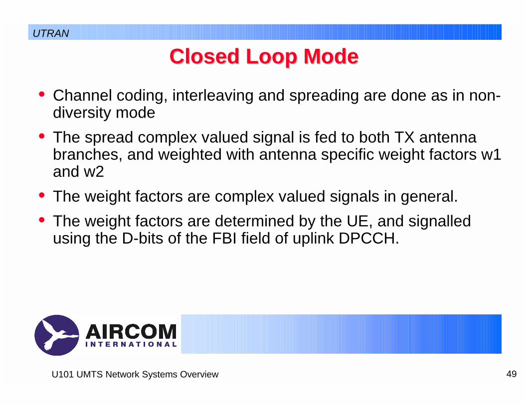
Closed Loop ModeClosed Loop Mode• Channel coding, interleaving and spreading are done as in non-
diversity mode• The spread complex valued signal is fed to both TX antenna
branches, and weighted with antenna specific weight factors w1 and w2
• The weight factors are complex valued signals in general.• The weight factors are determined by the UE, and signalled
using the D-bits of the FBI field of uplink DPCCH.
UTRAN
50U101 UMTS Network Systems Overview
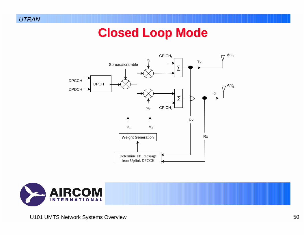
Closed Loop ModeClosed Loop Mode
Spread/scramblew1
w2
DPCHDPCCH
DPDCH
Rx
Rx
∑
CPICH1
Tx
∑
CPICH2
Ant1
Ant2
Tx
Weight Generation
w1 w2
Determine FBI messagefrom Uplink DPCCH
UTRAN

51U101 UMTS Network Systems Overview
Cell Search and Cell Search and SynchronisationSynchronisation• In UMTS base stations are not tightly synchronised (µs-level) to a common
reference, e.g. GPS• Makes for easier deployment, e.g. in indoor environments
! All cells transmit different scrambling codes plus common synchronisation code
• UE searches for primary synchronisation code with matched filter! Synchronises to new cell and acquires time slot clock
• UE decodes secondary synchronisation code! Identification of new cell! Radio frame synchronisation
• Can now find cell’s scrambling code from the CPICH to decode the Primary CCPCH
UTRAN
52U101 UMTS Network Systems Overview
Power ControlPower Control• Two Levels of Power Control
! Outer Loop" The RNC sets the target Eb/No based upon the BER of the received data
! Inner loop" Open loop based upon estimating the path loss from the pilot" Fast closed loop Power control on both the uplink and the downlink
– Based upon TPC bits– 2 algorithms
» Every received bit causes an adjustment in transmit power, either up or down» A set of commands is sent starting with a sequence of 4 0’s. Only if all 5 command
the bits indicate up is the power increased, all the bits down is the power decreased. Otherwise power remains the same
UTRAN
53U101 UMTS Network Systems Overview
Power Control in Soft HandoverPower Control in Soft Handover• In Soft Handover multiple power control measurements might
be received• In this case a simple rule is used
! If any command says power down, then power down! If all commands say power up, then power up
UTRAN

54U101 UMTS Network Systems Overview
QuestionsQuestions• What is the difference between load control and congestion
control?• How does handover for UMTS differ from that in cdmaOne?• If we are continuously receiving data, how do we take
measurements for MAHO?
UTRAN

55U101 UMTS Network Systems Overview
Session SummarySession Summary• In this session we have discussed the major elements and
procedures for UTRAN• In the next session we are going to look at the Core Network
UTRAN