UTP Welding Handbook English
431
www.utp-welding.com
description
UTP Welding Handbook English
Transcript of UTP Welding Handbook English
www.utp-welding.com
1
Manual stick electrodesSolid wires and rodsFlux cored wires Combinations of submerged arc wires and powdersMetal powders
A product range for fabrication, repair andmaintenance
UTP SchweissmaterialZweigniederlassung der Böhler Schweisstechnik Deutschland GmbHElsaesser Strasse 10D-79189 Bad KrozingenPhone +49 (0) 76 33 / 409-01Fax +49 (0) 76 33 / 409-222E-Mail [email protected] www.utp-welding.com
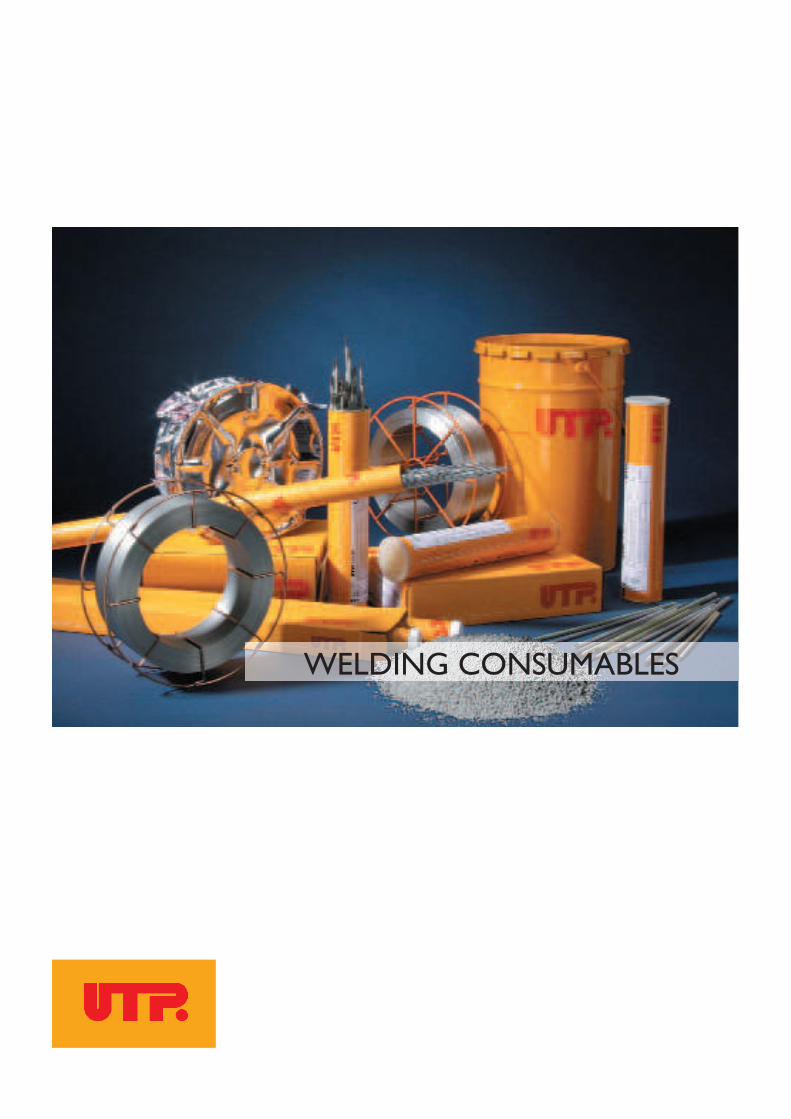
WELDING CONSUMABLES
3
UTP – five decades of experience in production, development and the distribution ofwelding consumables.The production programme that specialises in application techniques contains specialelectrodes in the corresponding special and standard alloys.In modern industrial society innovative ideas are translated into action only throughthe development of new materials. In close collaboration with well-known steel ma-nufacturers and with the most up-to-date technology UTP develops suitable weld fil-ler materials.A further essential factor of success is, the existing company philosophy, which has al-ways been the same: Welding solutions are developed in close collaboration with thecustomer and therefore reach a maximum amount of individuality in relation to ap-plicability. UTP products are applied in every branch of industry. A well-organized, technical sup-port service is available to our customers worldwide. UTP was the first European manufacturer of coated welding electrodes and the firstwelding industry supplier of high nickel containing, stainless steel qualities and shiel-ding gas qualities to receive the ASME certificate (American Society of Mechanical En-gineering) "Quality System Certificate (Materials)". UTP is also classified according toKTA 1408 and other individual certificates of diverse international classification com-panies. With the establishment of the quality system and the environmental management sy-stem according to DIN EN ISO 9001 and DIN EN ISO 14001, UTP documentsits responsibility for environmental protection and the quality requirements of themarket. Our highest goal is to protect the existing resources and to reduce as muchas possible environmental damages during the manufacture of our products.For these reasons the three letters U - T - P stand for welding specialist and the de-sign of a programme. In short, UTP spells success.
4
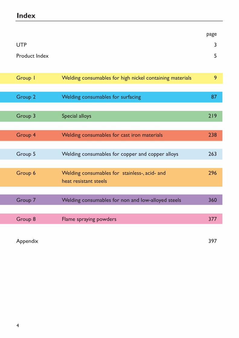
Indexpage
UTP 3Product Index 5
Group 1 Welding consumables for high nickel containing materials 9
Group 2 Welding consumables for surfacing 87
Group 3 Special alloys 219
Group 4 Welding consumables for cast iron materials 238
Group 5 Welding consumables for copper and copper alloys 263
Group 6 Welding consumables for stainless-, acid- and 296heat resistant steels
Group 7 Welding consumables for non and low-alloyed steels 360
Group 8 Flame spraying powders 377
Appendix 397
5
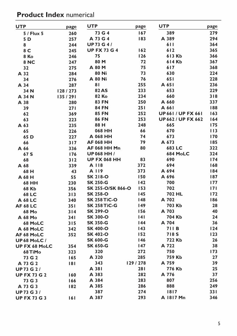
Product Index numericalUTP page
5 / Flux 5 2605 D 2578 2448 C 2458 Ko 2468 NC 24732 275
A 32 28434 276
A 34 28734 N 128 / 273
A 34 N 135 / 291A 38 28039 27162 36963 223
A 63 23565 22665 D 22766 317
A 66 33667 S 17668 312
A 68 33968 H 43
A 68 H 5568 HH 23068 Kb 35668 LC 313
A 68 LC 340AF 68 LC 351
68 Mo 314A 68 Mo 34168 MoLC 315
A 68 MoLC 342AF 68 MoLC 352UP68 MoLC /UP FX 68 MoLC 354
68 TiMo 32373 G 2 165
A 73 G 2 181UP73 G 2 /UP FX 73 G 2 160
73 G 3 166A 73 G 3 182UP73 G 3 /UP FX 73 G 3 161
UTP page73 G 4 167
A 73 G 4 183UP73 G 4 /UP FX 73 G 4 162
75 12680 M 72
A 80 M 7580 Ni 73
A 80 Ni 7681 25582 AS 23382 Ko 23483 FN 25084 FN 25185 FN 25286 FN 25388 H 248068 HH 66
A 068 HH 74AF 068 HH 79AF 068 HH Mn 80UP068 HH /UP FX 068 HH 83A 118 372A 119 373SK 218-O 150SK 250-G 142SK 255-O/SK 866-O 153SK 258-O 145SK 258 TiC-O 148SK 258 TiC-G 149SK 299-O 156SK 300-O 141SK 350-G 144SK 400-O 143SK 402-O 152SK 600-G 146SK 650-G 147
320 272A 320 285343 129 / 278
A 381 281A 383 282A 384 283A 385 286387 274
A 387 293
UTP page389 279
A 389 294611 364612 365613 Kb 366614 Kb 367617 368630 224651 228
A 651 236653 229660 318
A 660 337A 661 188UP661 / UP FX 661 163UP662 / UP FX 662 164
665 175670 113673 170
A 673 185683 LC 322684 MoLC 324690 174694 168
A 694 184A 696 187700 177702 171702 HL 172
A 702 186703 Kb 28
A 703 40704 Kb 24
A 704 36711 B 124718 S 123722 Kb 26
A 722 38750 173759 Kb 27
A 759 39776 Kb 25
A 776 37807 256888 2491817 331
A 1817 Mn 346
6
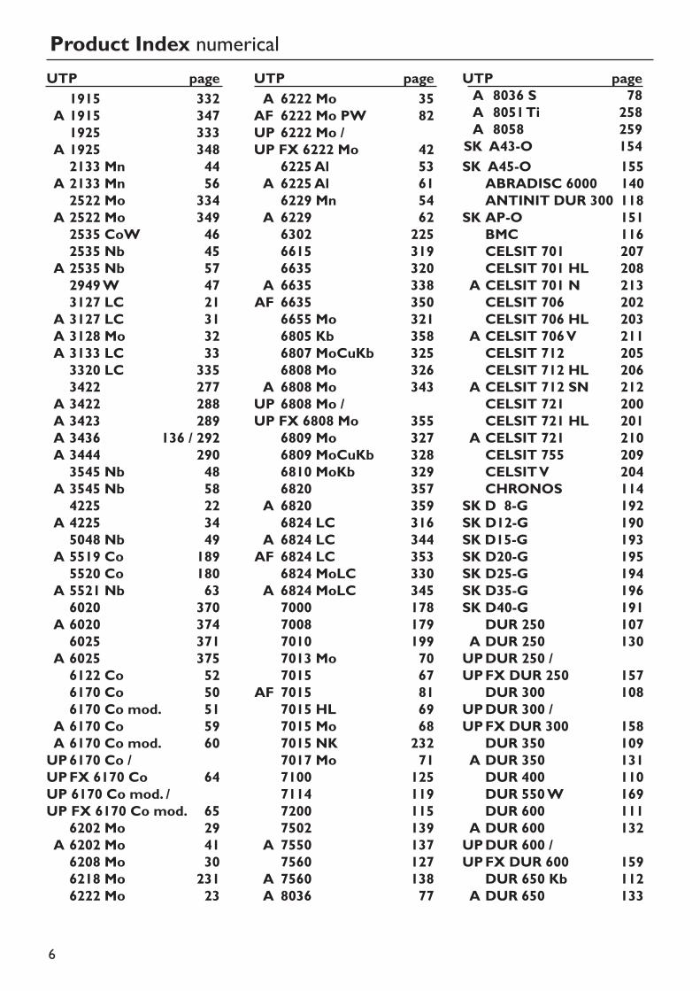
Product Index numericalUTP pageA 6222 Mo 35AF 6222 Mo PW 82UP 6222 Mo / UP FX 6222 Mo 42
6225 Al 53A 6225 Al 616229 Mn 54
A 6229 626302 2256615 3196635 320
A 6635 338AF 6635 350
6655 Mo 3216805 Kb 3586807 MoCuKb 3256808 Mo 326
A 6808 Mo 343UP 6808 Mo /UP FX 6808 Mo 355
6809 Mo 3276809 MoCuKb 3286810 MoKb 3296820 357
A 6820 3596824 LC 316
A 6824 LC 344AF 6824 LC 353
6824 MoLC 330A 6824 MoLC 3457000 1787008 1797010 1997013 Mo 707015 67
AF 7015 817015 HL 697015 Mo 687015 NK 2327017 Mo 717100 1257114 1197200 1157502 139
A 7550 1377560 127
A 7560 138A 8036 77
UTP pageA 8036 S 78A 8051 Ti 258A 8058 259SK A43-O 154SK A45-O 155
ABRADISC 6000 140ANTINIT DUR 300 118
SK AP-O 151BMC 116CELSIT 701 207CELSIT 701 HL 208
A CELSIT 701 N 213CELSIT 706 202CELSIT 706 HL 203
A CELSIT 706 V 211CELSIT 712 205CELSIT 712 HL 206
A CELSIT 712 SN 212CELSIT 721 200CELSIT 721 HL 201
A CELSIT 721 210CELSIT 755 209CELSIT V 204CHRONOS 114
SK D 8-G 192SK D12-G 190SK D15-G 193SK D20-G 195SK D25-G 194SK D35-G 196SK D40-G 191
DUR 250 107A DUR 250 130UPDUR 250 /UPFX DUR 250 157
DUR 300 108UPDUR 300 /UPFX DUR 300 158
DUR 350 109A DUR 350 131DUR 400 110DUR 550 W 169DUR 600 111
A DUR 600 132UPDUR 600 /UPFX DUR 600 159
DUR 650 Kb 112A DUR 650 133
UTP page1915 332
A 1915 3471925 333
A 1925 3482133 Mn 44
A 2133 Mn 562522 Mo 334
A 2522 Mo 3492535 CoW 462535 Nb 45
A 2535 Nb 572949 W 473127 LC 21
A 3127 LC 31A 3128 Mo 32A 3133 LC 333320 LC 3353422 277
A 3422 288A 3423 289A 3436 136 / 292A 3444 2903545 Nb 48
A 3545 Nb 584225 22
A 4225 345048 Nb 49
A 5519 Co 1895520 Co 180
A 5521 Nb 636020 370
A 6020 3746025 371
A 6025 3756122 Co 526170 Co 506170 Co mod. 51
A 6170 Co 59A 6170 Co mod. 60UP6170 Co /UPFX 6170 Co 64UP 6170 Co mod. /UP FX 6170 Co mod. 65
6202 Mo 29A 6202 Mo 416208 Mo 306218 Mo 2316222 Mo 23
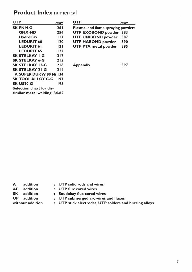
UTP pagePlasma- and flame spraying powdersUTP EXOBOND powder 383UTP UNIBOND powder 387UTP HABOND powder 390UTP PTA metal powder 395
Appendix 397
7
A addition : UTP solid rods and wiresAF addition : UTP flux cored wiresSK addition : Soudokay flux cored wiresUP addition : UTP submerged arc wires and fluxeswithout addition : UTP stick electrodes, UTP solders and brazing alloys
Product Index numericalUTP pageSK FNM-G 261
GNX-HD 254HydroCav 117LEDURIT 60 120LEDURIT 61 121LEDURIT 65 122
SK STELKAY 1-G 217SK STELKAY 6-G 215SK STELKAY 12-G 216SK STELKAY 21-G 214A SUPER DUR W 80 Ni 134SK TOOL ALLOY C-G 197SK U520-G 198Selection chart for dis-similar metal welding 84-85
8
9
Index
High corrosion applicationsHigh temperature applicationsNickel alloys
stick electrodessolid rods and wiresflux cored wireswires and fluxes for submerged-arc welding
Group 1Welding consumablesfor high nickel-contai-ning materials
9
10
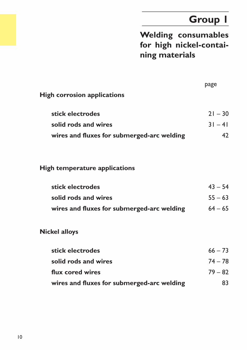
High corrosion applications
High temperature applications
Nickel alloys
stick electrodessolid rods and wireswires and fluxes for submerged-arc welding
21 – 3031 – 41
42
page xxx
43 – 5455 – 6364 – 65
66 – 7374 – 7879 – 82
83
stick electrodessolid rods and wireswires and fluxes for submerged-arc welding
stick electrodessolid rods and wiresflux cored wireswires and fluxes for submerged-arc welding
Group 1Welding consumablesfor high nickel-contai-ning materials
11
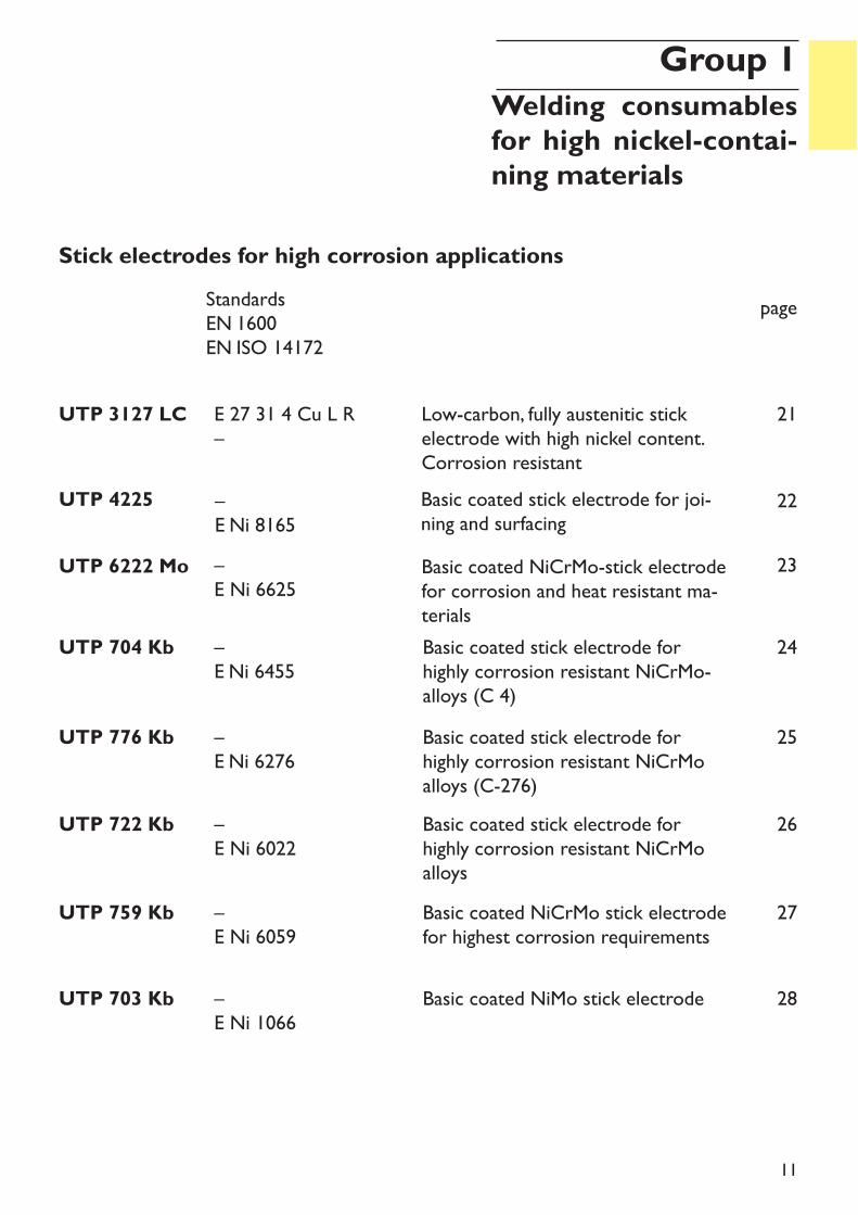
Stick electrodes for high corrosion applications
UTP 704 Kb –E Ni 6455
Basic coated stick electrode forhighly corrosion resistant NiCrMo-alloys (C 4)
page
24
UTP 3127 LC E 27 31 4 Cu L R–
Low-carbon, fully austenitic stickelectrode with high nickel content.Corrosion resistant
21
UTP 4225 –E Ni 8165
Basic coated stick electrode for joi-ning and surfacing
22
UTP 6222 Mo –E Ni 6625
Basic coated NiCrMo-stick electrodefor corrosion and heat resistant ma-terials
23
Group 1Welding consumablesfor high nickel-contai-ning materials
StandardsEN 1600EN ISO 14172
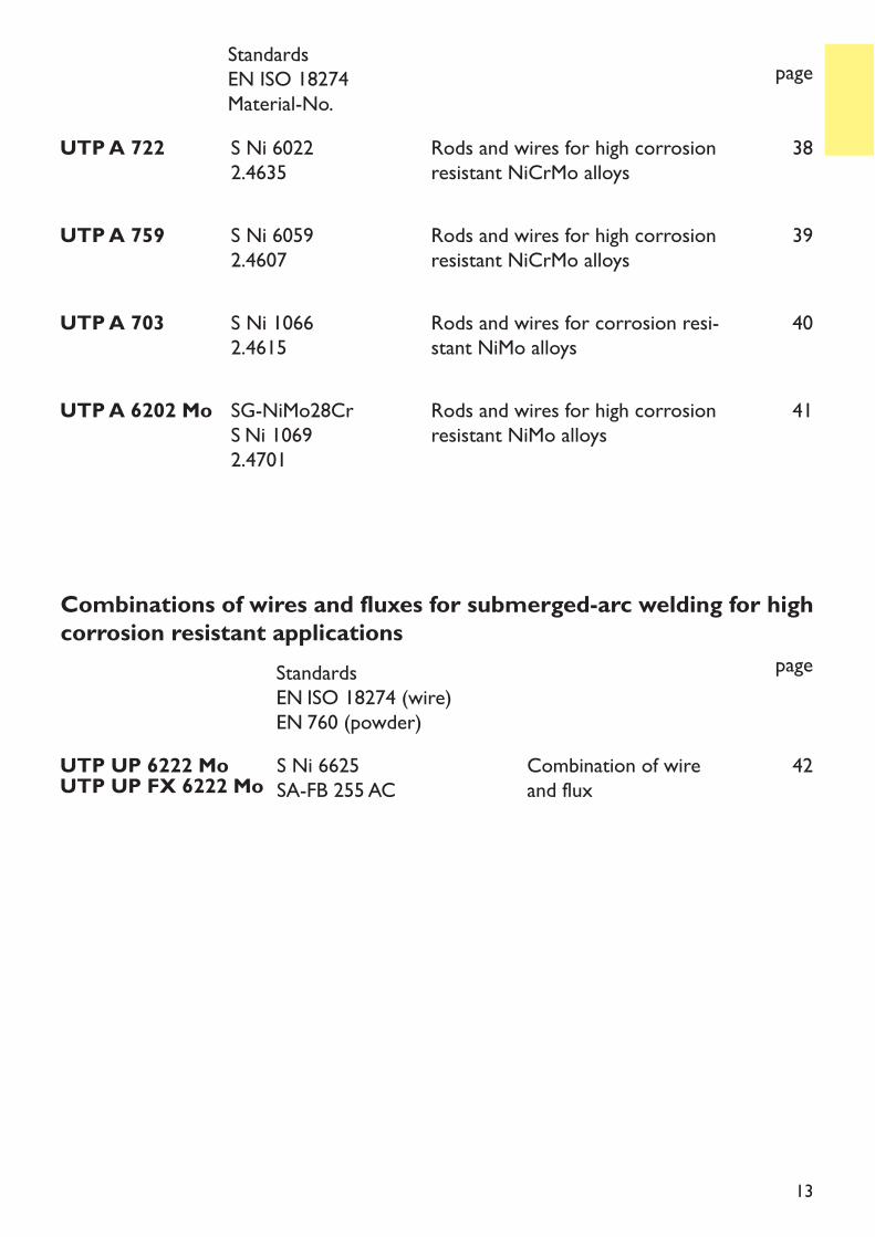
UTP 722 Kb –E Ni 6022
Basic coated stick electrode forhighly corrosion resistant NiCrMoalloys
26
UTP 776 Kb –E Ni 6276
Basic coated stick electrode forhighly corrosion resistant NiCrMoalloys (C-276)
25
UTP 703 Kb –E Ni 1066
Basic coated NiMo stick electrode 28
UTP 759 Kb –E Ni 6059
Basic coated NiCrMo stick electrodefor highest corrosion requirements
27
12
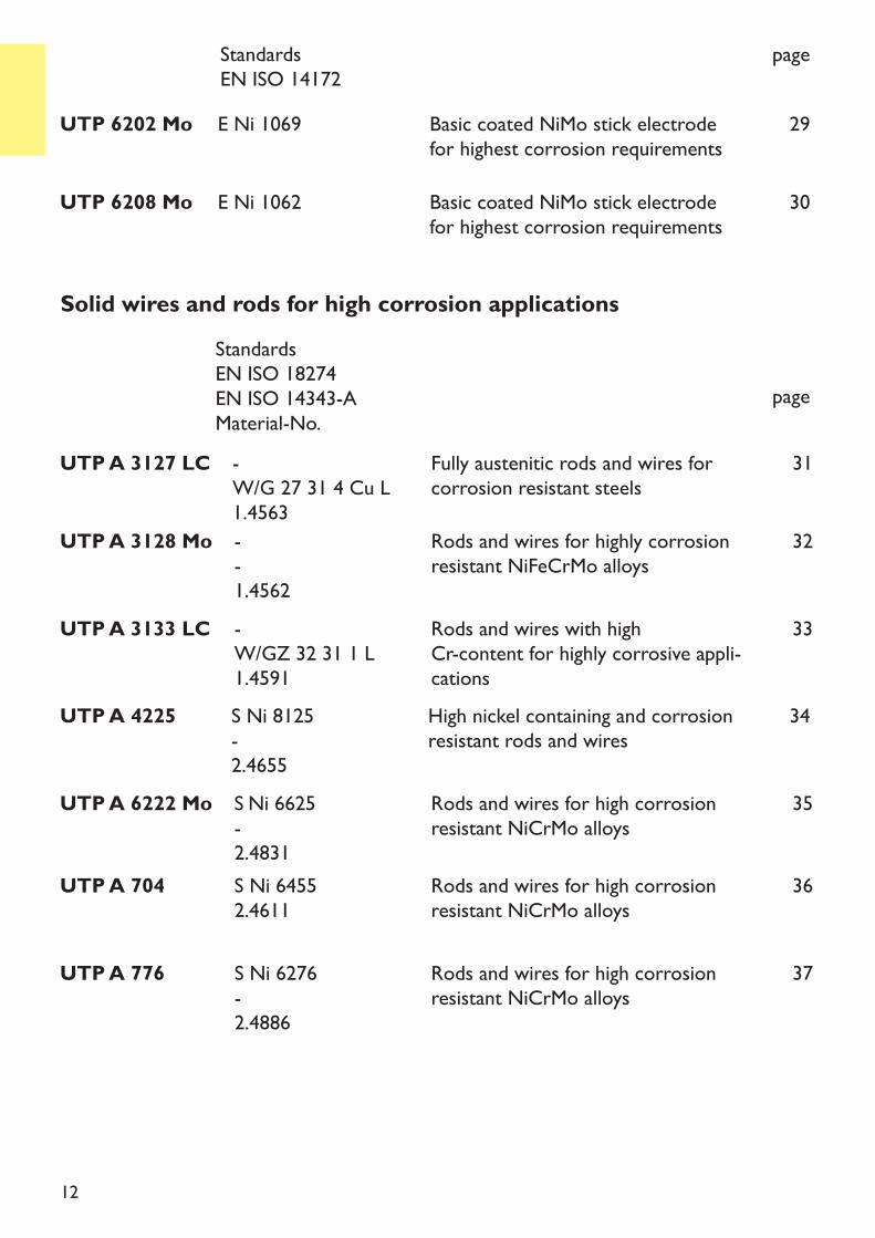
UTP 6208 Mo E Ni 1062 Basic coated NiMo stick electrodefor highest corrosion requirements
UTP 6202 Mo E Ni 1069 Basic coated NiMo stick electrodefor highest corrosion requirements
29
30
Solid wires and rods for high corrosion applicationsStandardsEN ISO 18274EN ISO 14343-AMaterial-No.
page
UTP A 3127 LC -W/G 27 31 4 Cu L1.4563
Fully austenitic rods and wires forcorrosion resistant steels
UTP A 3128 Mo --1.4562
Rods and wires for highly corrosionresistant NiFeCrMo alloys
31
32
StandardsEN ISO 14172
page
UTP A 3133 LC -W/GZ 32 31 1 L1.4591
Rods and wires with high Cr-content for highly corrosive appli-cations
33
UTP A 4225 S Ni 8125-2.4655
High nickel containing and corrosionresistant rods and wires
34
UTP A 6222 Mo S Ni 6625-2.4831
Rods and wires for high corrosionresistant NiCrMo alloys
35
UTP A 704 S Ni 64552.4611
Rods and wires for high corrosionresistant NiCrMo alloys
36
UTP A 776 S Ni 6276-2.4886
Rods and wires for high corrosionresistant NiCrMo alloys
37
13
UTP A 703 S Ni 10662.4615
Rods and wires for corrosion resi-stant NiMo alloys
40
UTP A 722 S Ni 60222.4635
Rods and wires for high corrosionresistant NiCrMo alloys
38
UTP A 759 S Ni 60592.4607
Rods and wires for high corrosionresistant NiCrMo alloys
39
UTP A 6202 Mo SG-NiMo28CrS Ni 10692.4701
Rods and wires for high corrosionresistant NiMo alloys
41
StandardsEN ISO 18274Material-No.
page
StandardsEN ISO 18274 (wire)EN 760 (powder)
page
Combinations of wires and fluxes for submerged-arc welding for highcorrosion resistant applications
UTP UP 6222 MoUTP UP FX 6222 Mo S Ni 6625SA-FB 255 AC
Combination of wire and flux
42
14
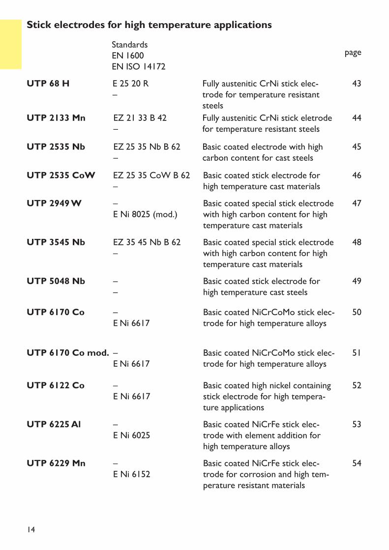
UTP 2133 Mn EZ 21 33 B 42–
Fully austenitic CrNi stick eletrodefor temperature resistant steels
UTP 2535 Nb EZ 25 35 Nb B 62–
Basic coated electrode with highcarbon content for cast steels
44
45
UTP 68 H E 25 20 R –
Fully austenitic CrNi stick elec-trode for temperature resistantsteels
43
Stick electrodes for high temperature applicationsStandardsEN 1600EN ISO 14172
page
UTP 6225 Al –E Ni 6025
Basic coated NiCrFe stick elec-trode with element addition forhigh temperature alloys
53
UTP 6229 Mn –E Ni 6152
Basic coated NiCrFe stick elec-trode for corrosion and high tem-perature resistant materials
54
UTP 3545 Nb EZ 35 45 Nb B 62–
Basic coated special stick electrodewith high carbon content for hightemperature cast materials
48
UTP 5048 Nb ––
Basic coated stick electrode forhigh temperature cast steels
49
UTP 6122 Co –E Ni 6617
Basic coated high nickel containingstick electrode for high tempera-ture applications
UTP 6170 Co –E Ni 6617
Basic coated NiCrCoMo stick elec-trode for high temperature alloys
52
50
UTP 2535 CoW EZ 25 35 CoW B 62–
Basic coated stick electrode forhigh temperature cast materials
UTP 2949 W –E Ni 8025 (mod.)
Basic coated special stick electrodewith high carbon content for hightemperature cast materials
46
47
UTP 6170 Co mod. –E Ni 6617
Basic coated NiCrCoMo stick elec-trode for high temperature alloys
51
15
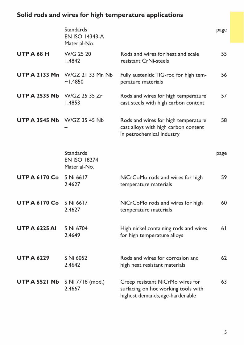
UTP A 6225 Al S Ni 67042.4649
High nickel containing rods and wiresfor high temperature alloys
61
UTP A 6229 S Ni 60522.4642
Rods and wires for corrosion andhigh heat resistant materials
62
UTP A 6170 Co S Ni 66172.4627
NiCrCoMo rods and wires for hightemperature materials
59
UTP A 2535 Nb W/GZ 25 35 Zr1.4853
Rods and wires for high temperaturecast steels with high carbon content
57
UTP A 5521 Nb S Ni 7718 (mod.)2.4667
Creep resistant NiCrMo wires forsurfacing on hot working tools withhighest demands, age-hardenable
63
UTP A 3545 Nb W/GZ 35 45 Nb–
Rods and wires for high temperaturecast alloys with high carbon contentin petrochemical industry
58
UTP A 68 H W/G 25 201.4842
Rods and wires for heat and scaleresistant CrNi-steels
55
Solid rods and wires for high temperature applicationsStandardsEN ISO 14343-AMaterial-No.
page
StandardsEN ISO 18274Material-No.
page
UTP A 2133 Mn W/GZ 21 33 Mn Nb~1.4850
Fully austenitic TIG-rod for high tem-perature materials
56
UTP A 6170 Co S Ni 66172.4627
NiCrCoMo rods and wires for hightemperature materials
60
16
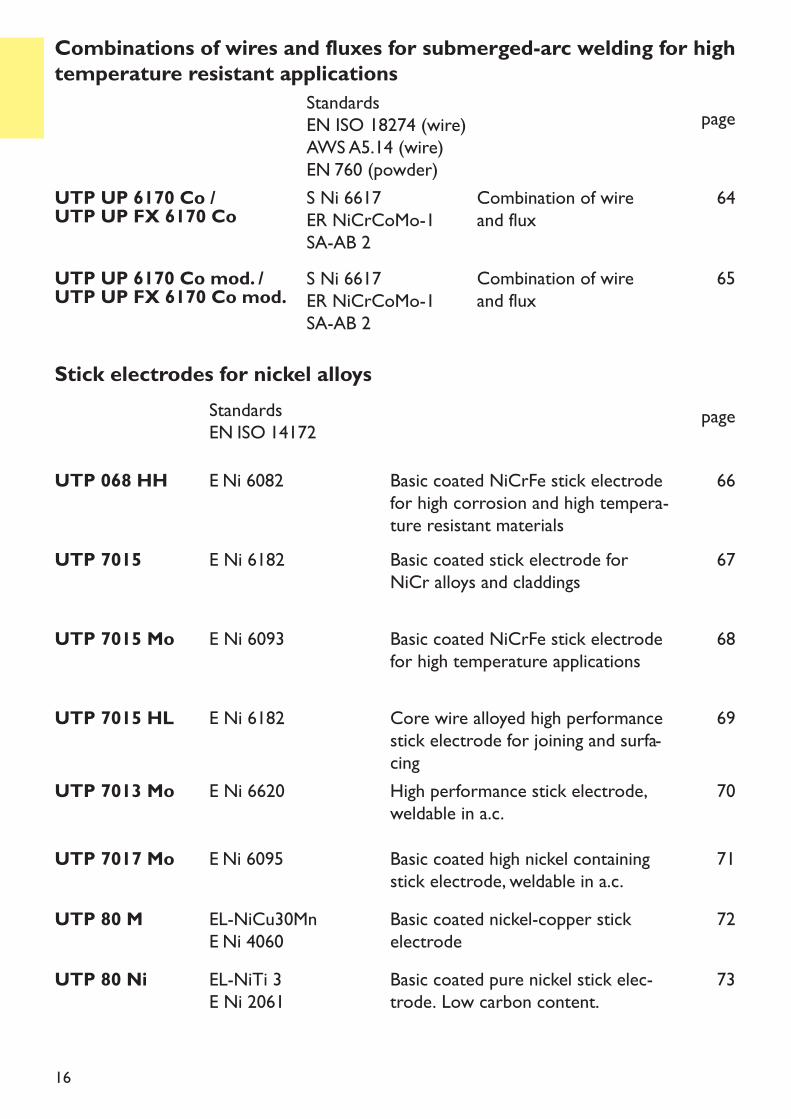
UTP UP 6170 Co /UTP UP FX 6170 Co S Ni 6617ER NiCrCoMo-1SA-AB 2
Combination of wire and flux
64
StandardsEN ISO 18274 (wire)AWS A5.14 (wire) EN 760 (powder)
page
Combinations of wires and fluxes for submerged-arc welding for hightemperature resistant applications
Stick electrodes for nickel alloysStandardsEN ISO 14172 page
UTP 068 HH E Ni 6082 Basic coated NiCrFe stick electrodefor high corrosion and high tempera-ture resistant materials
66
UTP 7015 E Ni 6182 Basic coated stick electrode forNiCr alloys and claddings
67
UTP 7015 HL E Ni 6182 Core wire alloyed high performancestick electrode for joining and surfa-cing
69
UTP 7013 Mo E Ni 6620 High performance stick electrode,weldable in a.c.
70
UTP 7015 Mo E Ni 6093 Basic coated NiCrFe stick electrodefor high temperature applications
68
UTP 7017 Mo E Ni 6095 Basic coated high nickel containingstick electrode, weldable in a.c.
71
UTP UP 6170 Co mod. /UTP UP FX 6170 Co mod. Combination of wire and flux
65S Ni 6617ER NiCrCoMo-1SA-AB 2
UTP 80 M EL-NiCu30MnE Ni 4060
Basic coated nickel-copper stickelectrode
72
UTP 80 Ni EL-NiTi 3E Ni 2061
Basic coated pure nickel stick elec-trode. Low carbon content.
73
1717
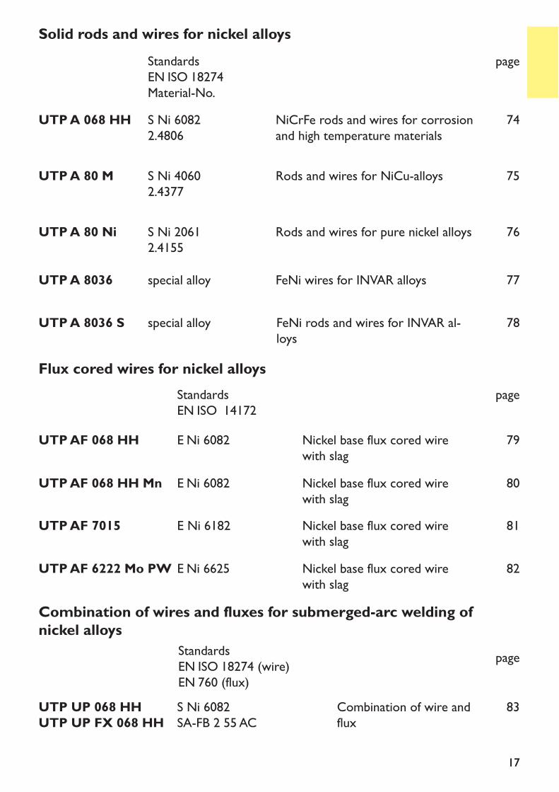
Solid rods and wires for nickel alloysStandardsEN ISO 18274Material-No.
page
UTP A 80 M S Ni 40602.4377
Rods and wires for NiCu-alloys
UTP A 80 Ni S Ni 20612.4155
Rods and wires for pure nickel alloys
UTP A 068 HH S Ni 60822.4806
NiCrFe rods and wires for corrosionand high temperature materials
74
75
76
UTP A 8036 S 78
UTP A 8036 FeNi wires for INVAR alloysspecial alloy
special alloy FeNi rods and wires for INVAR al-loys
77
Flux cored wires for nickel alloysStandardsEN ISO 14172
page
UTP AF 068 HH E Ni 6082 Nickel base flux cored wirewith slag
79
UTP AF 7015 E Ni 6182 Nickel base flux cored wirewith slag
81
StandardsEN ISO 18274 (wire)EN 760 (flux)
page
Combination of wires and fluxes for submerged-arc welding ofnickel alloys
UTP UP 068 HHUTP UP FX 068 HH
S Ni 6082SA-FB 2 55 AC
Combination of wire andflux
83
UTP AF 6222 Mo PW E Ni 6625 Nickel base flux cored wirewith slag
82
UTP AF 068 HH Mn E Ni 6082 Nickel base flux cored wirewith slag
80
18
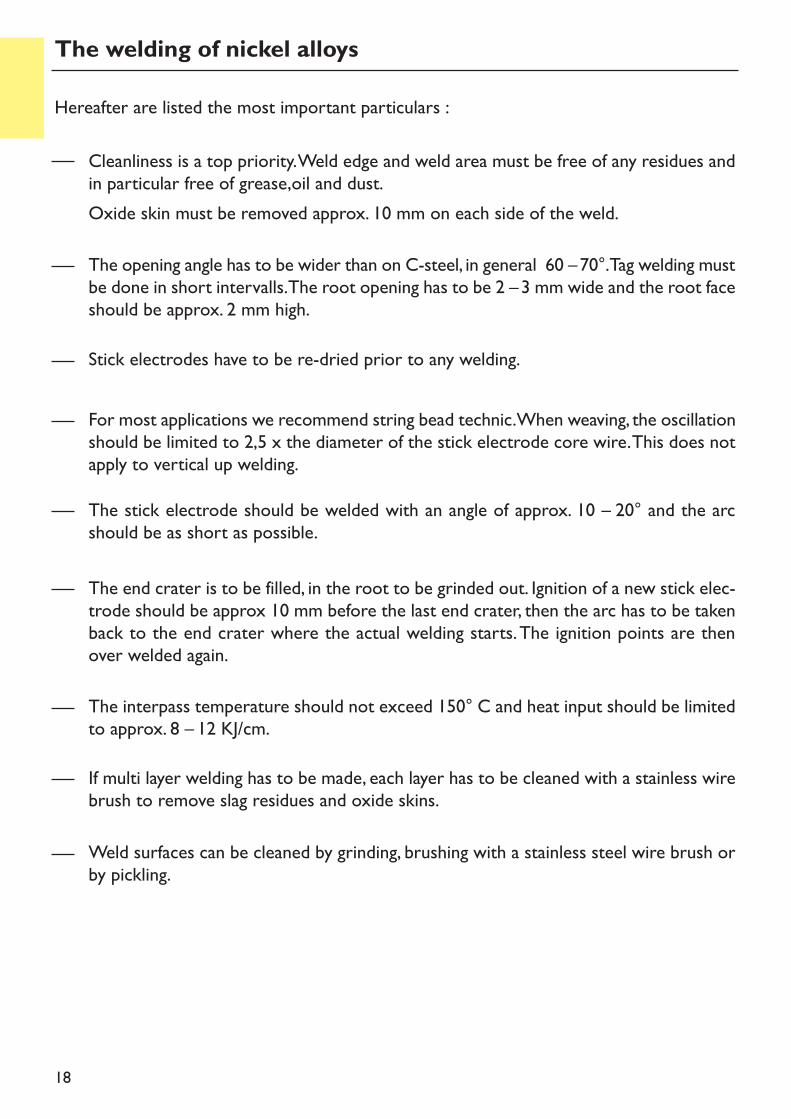
Hereafter are listed the most important particulars :
Cleanliness is a top priority. Weld edge and weld area must be free of any residues andin particular free of grease,oil and dust.Oxide skin must be removed approx. 10 mm on each side of the weld.
For most applications we recommend string bead technic. When weaving, the oscillationshould be limited to 2,5 x the diameter of the stick electrode core wire. This does notapply to vertical up welding.The stick electrode should be welded with an angle of approx. 10 – 20° and the arcshould be as short as possible.
The end crater is to be filled, in the root to be grinded out. Ignition of a new stick elec-trode should be approx 10 mm before the last end crater, then the arc has to be takenback to the end crater where the actual welding starts. The ignition points are thenover welded again.
The interpass temperature should not exceed 150° C and heat input should be limitedto approx. 8 – 12 KJ/cm.
Weld surfaces can be cleaned by grinding, brushing with a stainless steel wire brush orby pickling.
If multi layer welding has to be made, each layer has to be cleaned with a stainless wirebrush to remove slag residues and oxide skins.
Stick electrodes have to be re-dried prior to any welding.
The welding of nickel alloys
The opening angle has to be wider than on C-steel, in general 60 –70°. Tag welding mustbe done in short intervalls. The root opening has to be 2 –3 mm wide and the root faceshould be approx. 2 mm high.
19
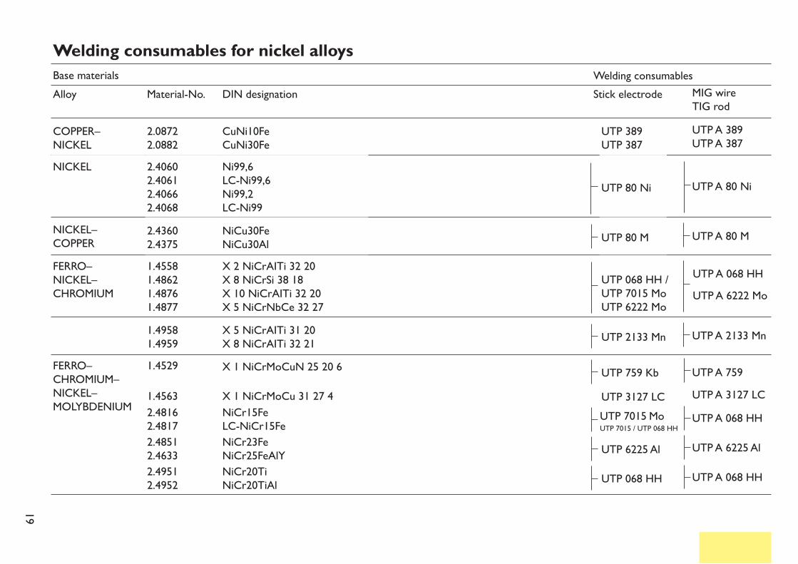
Welding consumables for nickel alloysBase materialsAlloy
NICKEL–COPPER
NICKEL
FERRO–CHROMIUM–NICKEL–MOLYBDENIUM
FERRO–NICKEL–CHROMIUM
UTP 3127 LC
UTP 6225 AlUTP 068 HH
2.43602.4375
1.49581.4959
X 5 NiCrAITi 31 20X 8 NiCrAITi 32 21 UTP 2133 Mn UTP A 2133 Mn
X 1 NiCrMoCuN 25 20 6X 1 NiCrMoCu 31 27 41.4563NiCr15FeLC-NiCr15FeNiCr23FeNiCr25FeAlYNiCr20TiNiCr20TiAl
2.49512.4952
2.48512.4633
2.48162.4817
1.4529 UTP 759 Kb
UTP A 068 HHUTP A 6222 Mo
UTP 068 HH /UTP 7015 MoUTP 6222 Mo
UTP 80 M UTP A 80 M
UTP A 759
UTP 80 Ni UTP A 80 Ni
X 2 NiCrAITi 32 20X 8 NiCrSi 38 18X 10 NiCrAITi 32 20X 5 NiCrNbCe 32 27
NiCu30FeNiCu30Al
1.45581.48621.48761.4877
Ni99,6LC-Ni99,6Ni99,2LC-Ni99
2.40602.40612.40662.4068
COPPER–NICKEL
UTP 389UTP 387
UTP A 389UTP A 387CuNi10Fe
CuNi30Fe2.08722.0882
UTP A 3127 LCUTP A 068 HHUTP A 6225 AlUTP A 068 HH
Material-No. DIN designation Stick electrodeWelding consumables
MIG wireTIG rod
UTP 7015 MoUTP 7015 / UTP 068 HH
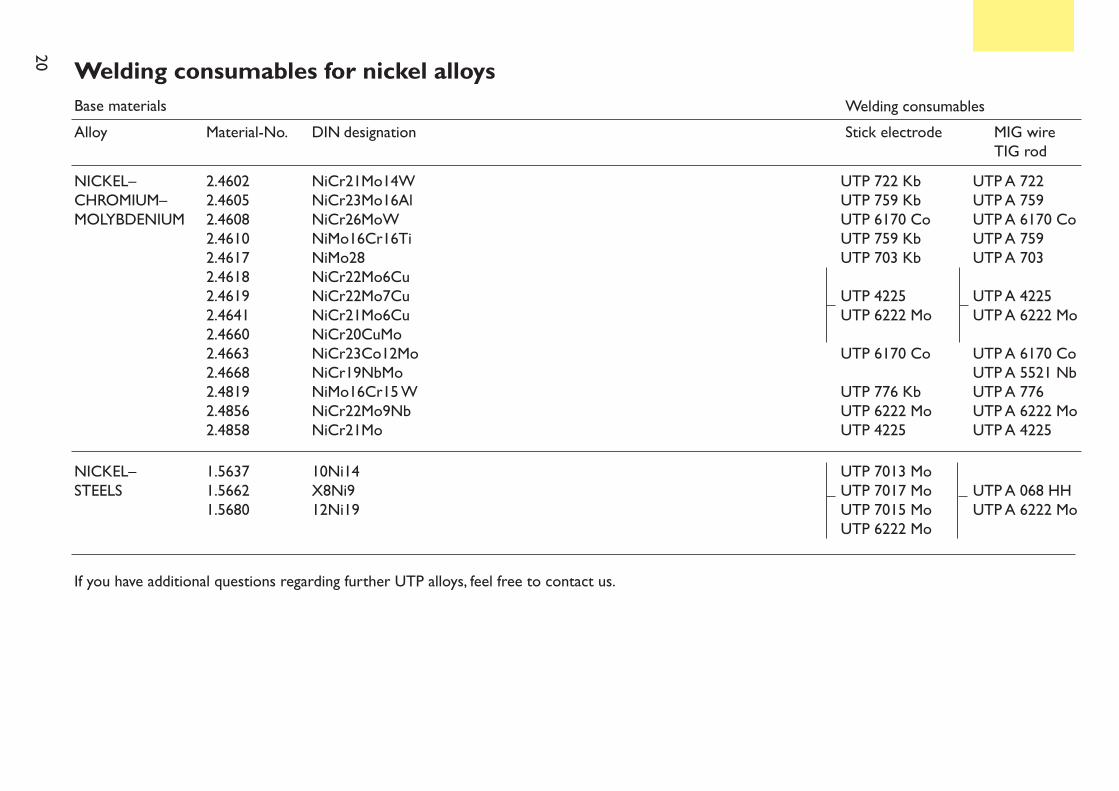
20 Welding consumables for nickel alloysBase materialsAlloy
NICKEL–CHROMIUM–MOLYBDENIUM
UTP 722 KbUTP 759 KbUTP 6170 CoUTP 759 KbUTP 703 KbUTP 4225UTP 6222 MoUTP 6170 CoUTP 776 KbUTP 6222 MoUTP 4225
UTP A 722UTP A 759UTP A 6170 CoUTP A 759UTP A 703UTP A 4225UTP A 6222 MoUTP A 6170 CoUTP A 5521 NbUTP A 776UTP A 6222 MoUTP A 4225
NiCr21Mo14WNiCr23Mo16AlNiCr26MoWNiMo16Cr16TiNiMo28NiCr22Mo6CuNiCr22Mo7CuNiCr21Mo6CuNiCr20CuMoNiCr23Co12MoNiCr19NbMoNiMo16Cr15 WNiCr22Mo9NbNiCr21Mo
2.46022.46052.46082.46102.46172.46182.46192.46412.46602.46632.46682.48192.48562.4858
NICKEL–STEELS
UTP 7013 MoUTP 7017 MoUTP 7015 MoUTP 6222 Mo
UTP A 068 HHUTP A 6222 Mo
10Ni14X8Ni912Ni19
1.56371.56621.5680
Material-No.
If you have additional questions regarding further UTP alloys, feel free to contact us.
Stick electrodeWelding consumables
MIG wireTIG rod
DIN designation
21
Low-carbon, fully austenitic stickelectrode with high nickel content.Corrosion resistant
UTP 3127 LC
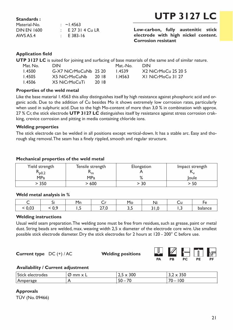
Welding instructionsUsual weld seam preparation. The welding zone must be free from residues, such as grease, paint or metaldust. String beads are welded, max. weaving width 2,5 x diameter of the electrode core wire. Use smallestpossible stick electrode diameter. Dry the stick electrodes for 2 hours at 120 - 200° C before use.
ApprovalsTÜV (No. 09466)
Weld metal analysis in %
Availability / Current adjustment
Standards :Material-No. : ~1.4563DIN EN 1600 : E 27 31 4 Cu LRAWS A5.4 : E 383-16
C< 0,03
Si< 0,9
Mn1,5
Cr27,0
Ni31,0
Mo3,5
Cu1,3
Febalance
Current type DC (+) / AC
Application fieldUTP 3127 LC is suited for joining and surfacing of base materials of the same and of similar nature.Mat. No. DIN Mat.-No. DIN 1.4500 G-X7 NiCrMoCuNb 25 20 1.4539 X2 NiCrMoCu 25 20 51.4505 X5 NiCrMoCuNb 20 18 1.l4563 X1 NiCrMoCu 31 271.4506 X5 NiCrMoCuTi 20 18
Properties of the weld metalLike the base material 1.4563 this alloy distinguishes itself by high resistance against phosphoric acid and or-ganic acids. Due to the addition of Cu besides Mo it shows extremely low corrosion rates, particularlywhen used in sulphuric acid. Due to the high Mo-content of more than 3,0 % in combination with approx.27 % Cr, the stick electrode UTP 3127 LC distinguishes itself by resistance against stress corrosion crak-king, crevice corrosion and pitting in media containing chloride ions.Welding propertiesThe stick electrode can be welded in all positions except vertical-down. It has a stable arc. Easy and tho-rough slag removal. The seam has a finely rippled, smooth and regular structure.
Stick electrodesAmperage
Ø mm x LA
2,5 x 30050 – 70
3,2 x 35070 – 100
Yield strengthRp0,2MPa> 350
Tensile strengthRmMPa> 600
Elongation A%> 30
Impact strengthKvJoule> 50
Mechanical properties of the weld metal
Welding positionsPA PB PC PE PF
22
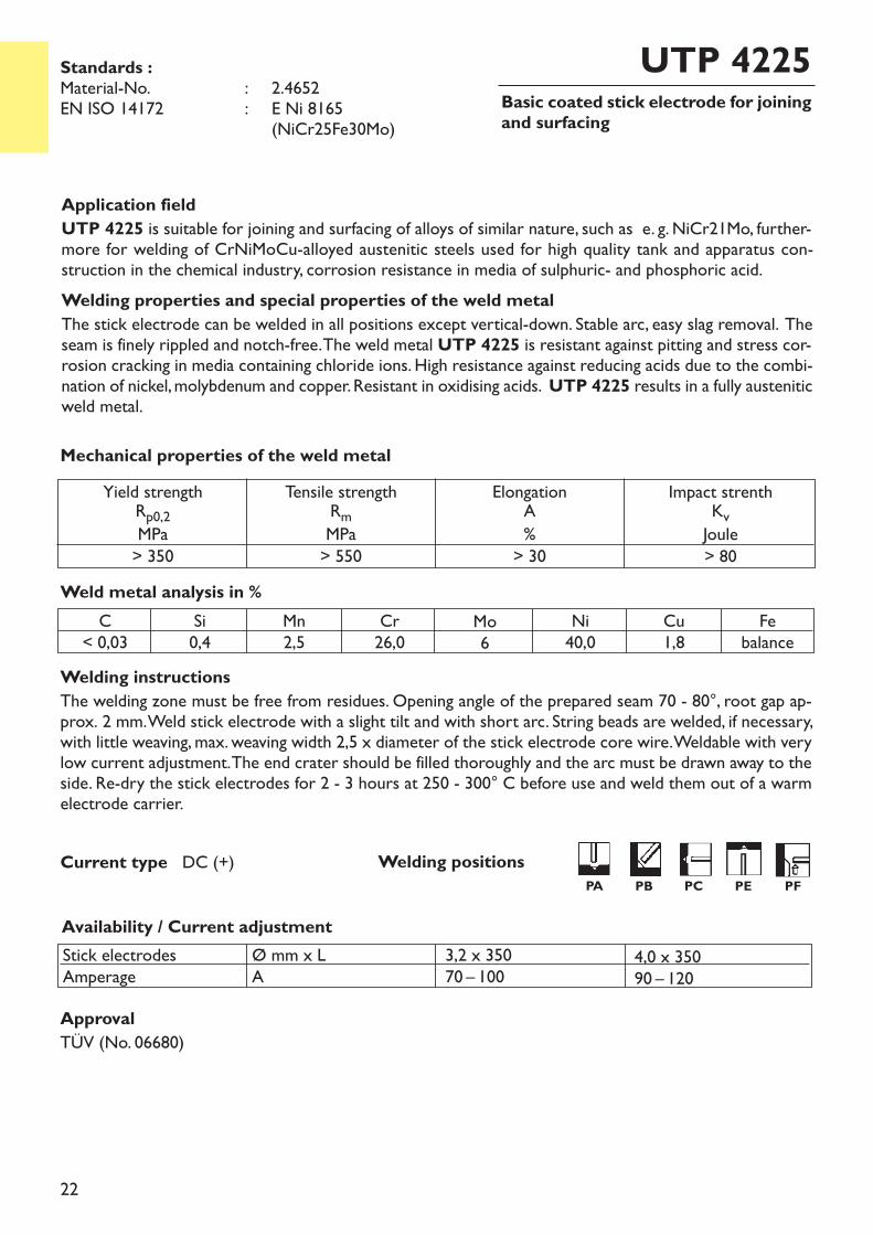
Basic coated stick electrode for joiningand surfacing
UTP 4225
Welding instructionsThe welding zone must be free from residues. Opening angle of the prepared seam 70 - 80°, root gap ap-prox. 2 mm. Weld stick electrode with a slight tilt and with short arc. String beads are welded, if necessary,with little weaving, max. weaving width 2,5 x diameter of the stick electrode core wire. Weldable with verylow current adjustment. The end crater should be filled thoroughly and the arc must be drawn away to theside. Re-dry the stick electrodes for 2 - 3 hours at 250 - 300° C before use and weld them out of a warmelectrode carrier.
ApprovalTÜV (No. 06680)
Current type DC (+)
Application fieldUTP 4225 is suitable for joining and surfacing of alloys of similar nature, such as e. g. NiCr21Mo, further-more for welding of CrNiMoCu-alloyed austenitic steels used for high quality tank and apparatus con-struction in the chemical industry, corrosion resistance in media of sulphuric- and phosphoric acid. Welding properties and special properties of the weld metalThe stick electrode can be welded in all positions except vertical-down. Stable arc, easy slag removal. Theseam is finely rippled and notch-free. The weld metal UTP 4225 is resistant against pitting and stress cor-rosion cracking in media containing chloride ions. High resistance against reducing acids due to the combi-nation of nickel, molybdenum and copper. Resistant in oxidising acids. UTP 4225 results in a fully austeniticweld metal.
Weld metal analysis in %
Availability / Current adjustmentStick electrodesAmperage
Ø mm x LA
3,2 x 35070 – 100
4,0 x 35090 – 120
C< 0,03
Si0,4
Mn2,5
Cr26,0
Ni40,0
Mo6
Cu1,8
Febalance
Mechanical properties of the weld metal
Standards :Material-No. : 2.4652EN ISO 14172 : E Ni 8165
(NiCr25Fe30Mo)
Yield strengthRp0,2MPa> 350
Tensile strengthRmMPa> 550
ElongationA%> 30
Impact strenthKvJoule> 80
Welding positionsPA PB PC PE PF
23
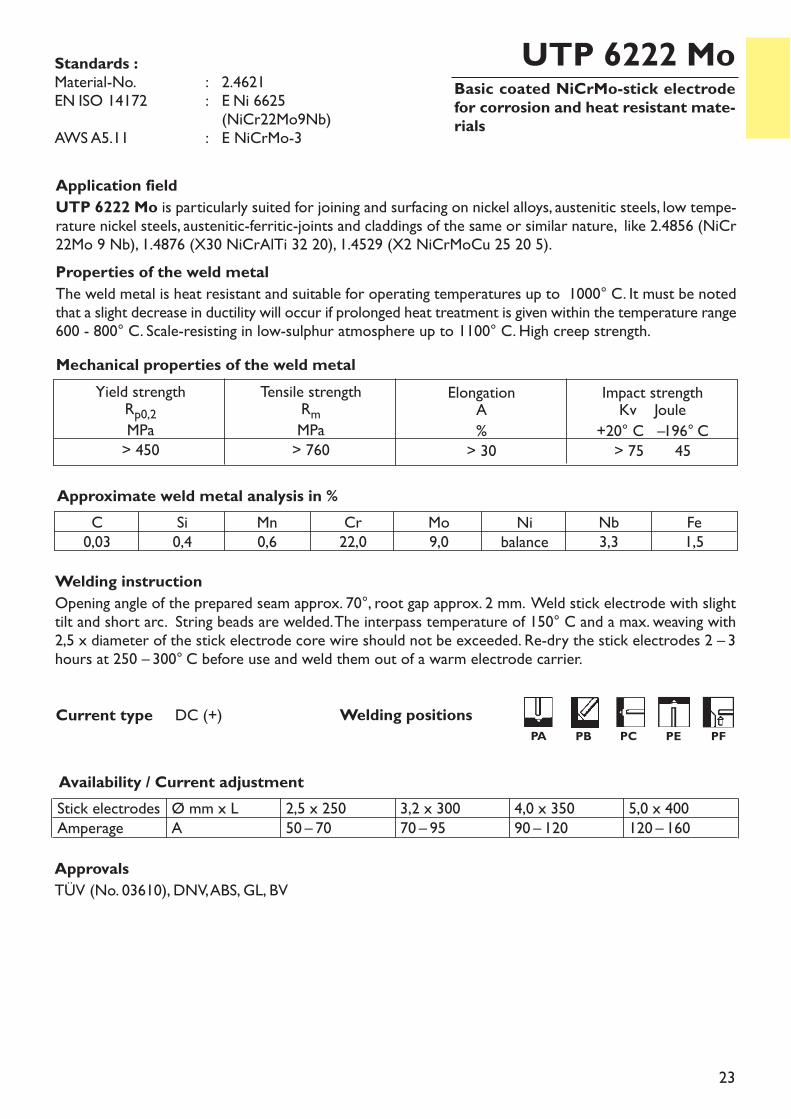
Basic coated NiCrMo-stick electrodefor corrosion and heat resistant mate-rials
UTP 6222 Mo
Welding instructionOpening angle of the prepared seam approx. 70°, root gap approx. 2 mm. Weld stick electrode with slighttilt and short arc. String beads are welded. The interpass temperature of 150° C and a max. weaving with2,5 x diameter of the stick electrode core wire should not be exceeded. Re-dry the stick electrodes 2 – 3hours at 250 – 300° C before use and weld them out of a warm electrode carrier.
Availability / Current adjustment
Application fieldUTP 6222 Mo is particularly suited for joining and surfacing on nickel alloys, austenitic steels, low tempe-rature nickel steels, austenitic-ferritic-joints and claddings of the same or similar nature, like 2.4856 (NiCr22Mo 9 Nb), 1.4876 (X30 NiCrAlTi 32 20), 1.4529 (X2 NiCrMoCu 25 20 5). Properties of the weld metalThe weld metal is heat resistant and suitable for operating temperatures up to 1000° C. It must be notedthat a slight decrease in ductility will occur if prolonged heat treatment is given within the temperature range600 - 800° C. Scale-resisting in low-sulphur atmosphere up to 1100° C. High creep strength.
Approximate weld metal analysis in %C0,03
Si0,4
Mn0,6
Cr22,0
Mo9,0
Nb3,3
Fe1,5
Nibalance
Stick electrodesAmperage
Ø mm x LA
2,5 x 25050 – 70
3,2 x 30070 – 95
4,0 x 35090 – 120
5,0 x 400120 – 160
Yield strengthRp0,2MPa> 450
Tensile strengthRmMPa> 760
Elongation A%> 30
Impact strengthKv Joule+20° C –196° C> 75 45
Mechanical properties of the weld metal
Current type DC (+)
Standards :Material-No. : 2.4621EN ISO 14172 : E Ni 6625
(NiCr22Mo9Nb)AWS A5.11 : E NiCrMo-3
ApprovalsTÜV (No. 03610), DNV, ABS, GL, BV
Welding positionsPA PB PC PE PF
24
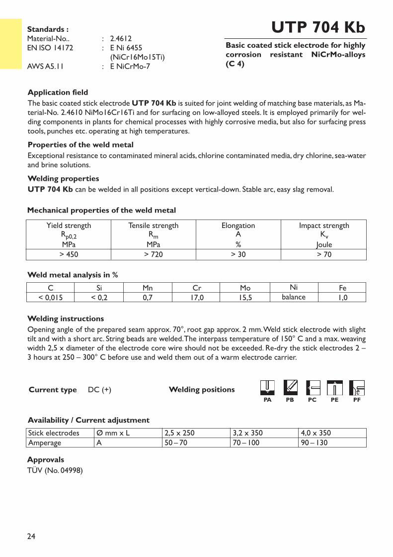
Basic coated stick electrode for highlycorrosion resistant NiCrMo-alloys(C 4)
UTP 704 Kb
Welding instructionsOpening angle of the prepared seam approx. 70°, root gap approx. 2 mm. Weld stick electrode with slighttilt and with a short arc. String beads are welded. The interpass temperature of 150° C and a max. weavingwidth 2,5 x diameter of the electrode core wire should not be exceeded. Re-dry the stick electrodes 2 –3 hours at 250 – 300° C before use and weld them out of a warm electrode carrier.
Current type DC (+)
Application fieldThe basic coated stick electrodeUTP 704 Kb is suited for joint welding of matching base materials, as Ma-terial-No. 2.4610 NiMo16Cr16Ti and for surfacing on low-alloyed steels. It is employed primarily for wel-ding components in plants for chemical processes with highly corrosive media, but also for surfacing presstools, punches etc. operating at high temperatures.Properties of the weld metalExceptional resistance to contaminated mineral acids, chlorine contaminated media, dry chlorine, sea-waterand brine solutions.Welding propertiesUTP 704 Kb can be welded in all positions except vertical-down. Stable arc, easy slag removal.
Weld metal analysis in %
Availability / Current adjustmentStick electrodesAmperage
Ø mm x LA
2,5 x 25050 – 70
3,2 x 35070 – 100
4,0 x 35090 – 130
C< 0,015
Si< 0,2
Mn0,7
Nibalance
Cr17,0
Mo15,5
Fe1,0
Yield strengthRp0,2MPa> 450
Tensile strengthRmMPa> 720
ElongationA%> 30
Impact strengthKvJoule> 70
Mechanical properties of the weld metal
Standards :Material-No.. : 2.4612EN ISO 14172 : E Ni 6455
(NiCr16Mo15Ti)AWS A5.11 : E NiCrMo-7
ApprovalsTÜV (No. 04998)
Welding positionsPA PB PC PE PF
25
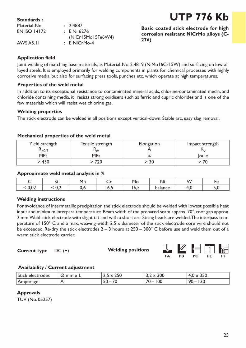
Basic coated stick electrode for highcorrosion resistant NiCrMo alloys (C-276)
UTP 776 Kb
Welding instructionsFor avoidance of intermetallic precipitation the stick electrode should be welded with lowest possible heatinput and minimum interpass temperature. Beam width of the prepared seam approx. 70°, root gap approx.2 mm. Weld stick electrode with slight tilt and with a short arc. String beads are welded. The interpass tem-perature of 150° C and a max. weaving width 2,5 x diameter of the stick electrode core wire should notbe exceeded. Re-dry the stick electrodes 2 – 3 hours at 250 – 300° C before use and weld them out of awarm stick electrode carrier.
Availability / Current adjustment
Application fieldJoint welding of matching base materials, as Material-No. 2.4819 (NiMo16Cr15W) and surfacing on low-al-loyed steels. It is employed primarily for welding components in plants for chemical processes with highlycorrosive media, but also for surfacing press tools, punches etc. which operate at high temperatures.Properties of the weld metalIn addition to its exceptional resistance to contaminated mineral acids, chlorine-contaminated media, andchloride containing media, it resists strong oxidisers such as ferric and cupric chlorides and is one of thefew materials which will resist wet chlorine gas.Welding properties The stick electrode can be welded in all positions except vertical-down. Stable arc, easy slag removal.
Approximate weld metal analysis in %C
< 0,02Si< 0,2
Mn0,6
Nibalance
Cr16,5
Mo16,5
W4,0
Fe5,0
Stick electrodesAmperage
Ø mm x LA
2,5 x 25050 – 70
3,2 x 30070 – 100
4,0 x 35090 – 130
Yield strengthRp0,2MPa> 450
Tensile strengthRmMPa> 720
Elongation A%> 30
Impact strengthKvJoule> 70
Mechanical properties of the weld metal
Current type DC (+)
Standards :Material-No. : 2.4887EN ISO 14172 : E Ni 6276
(NiCr15Mo15Fe6W4)AWS A5.11 : E NiCrMo-4
ApprovalsTÜV (No. 05257)
Welding positionsPA PB PC PE PF
26
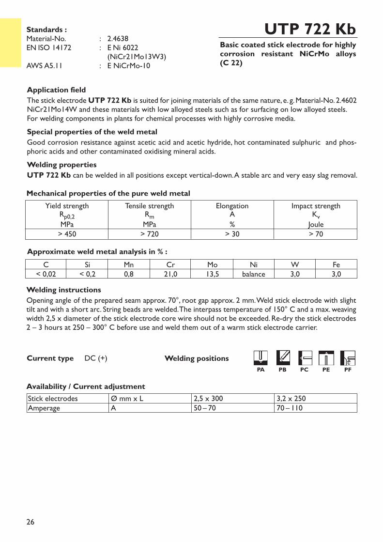
Basic coated stick electrode for highlycorrosion resistant NiCrMo alloys(C 22)
UTP 722 Kb
Welding instructionsOpening angle of the prepared seam approx. 70°, root gap approx. 2 mm. Weld stick electrode with slighttilt and with a short arc. String beads are welded. The interpass temperature of 150° C and a max. weavingwidth 2,5 x diameter of the stick electrode core wire should not be exceeded. Re-dry the stick electrodes2 – 3 hours at 250 – 300° C before use and weld them out of a warm stick electrode carrier.
Application fieldThe stick electrode UTP 722 Kb is suited for joining materials of the same nature, e. g. Material-No. 2.4602NiCr21Mo14W and these materials with low alloyed steels such as for surfacing on low alloyed steels.For welding components in plants for chemical processes with highly corrosive media. Special properties of the weld metalGood corrosion resistance against acetic acid and acetic hydride, hot contaminated sulphuric and phos-phoric acids and other contaminated oxidising mineral acids.Welding propertiesUTP 722 Kb can be welded in all positions except vertical-down. A stable arc and very easy slag removal.
Approximate weld metal analysis in % :C
< 0,02Si< 0,2
Mn0,8
Cr21,0
Mo13,5
W3,0
Fe3,0
Nibalance
Stick electrodesAmperage
Ø mm x LA
2,5 x 30050 – 70
3,2 x 25070 – 110
Availability / Current adjustment
Yield strengthRp0,2MPa> 450
Tensile strengthRmMPa> 720
ElongationA%> 30
Impact strengthKvJoule> 70
Mechanical properties of the pure weld metal
Current type DC (+)
Standards :Material-No. : 2.4638EN ISO 14172 : E Ni 6022
(NiCr21Mo13W3)AWS A5.11 : E NiCrMo-10
Welding positionsPA PB PC PE PF
27
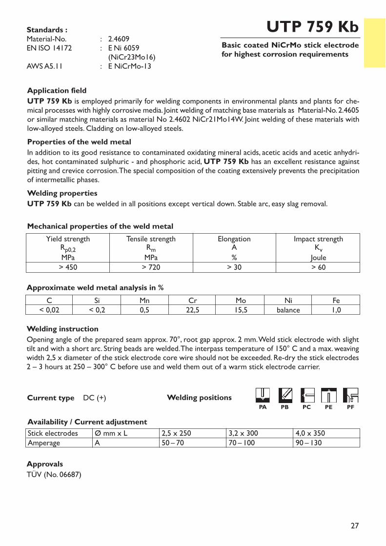
Basic coated NiCrMo stick electrodefor highest corrosion requirements
UTP 759 Kb
Welding instructionOpening angle of the prepared seam approx. 70°, root gap approx. 2 mm. Weld stick electrode with slighttilt and with a short arc. String beads are welded. The interpass temperature of 150° C and a max. weavingwidth 2,5 x diameter of the stick electrode core wire should not be exceeded. Re-dry the stick electrodes2 – 3 hours at 250 – 300° C before use and weld them out of a warm stick electrode carrier.
Availability / Current adjustment
Current type DC (+)
Application fieldUTP 759 Kb is employed primarily for welding components in environmental plants and plants for che-mical processes with highly corrosive media. Joint welding of matching base materials as Material-No. 2.4605or similar matching materials as material No 2.4602 NiCr21Mo14W. Joint welding of these materials withlow-alloyed steels. Cladding on low-alloyed steels.Properties of the weld metalIn addition to its good resistance to contaminated oxidating mineral acids, acetic acids and acetic anhydri-des, hot contaminated sulphuric - and phosphoric acid, UTP 759 Kb has an excellent resistance againstpitting and crevice corrosion. The special composition of the coating extensively prevents the precipitationof intermetallic phases.Welding propertiesUTP 759 Kb can be welded in all positions except vertical down. Stable arc, easy slag removal.
Approximate weld metal analysis in %C
< 0,02Si< 0,2
Mn0,5
Cr22,5
Mo15,5
Nibalance
Fe1,0
Stick electrodesAmperage
Ø mm x LA
2,5 x 25050 – 70
3,2 x 30070 – 100
4,0 x 35090 – 130
Yield strengthRp0,2MPa> 450
Tensile strengthRmMPa> 720
ElongationA%> 30
Impact strengthKvJoule> 60
Mechanical properties of the weld metal
Standards :Material-No. : 2.4609EN ISO 14172 : E Ni 6059
(NiCr23Mo16)AWS A5.11 : E NiCrMo-13
ApprovalsTÜV (No. 06687)
Welding positionsPA PB PC PE PF
28
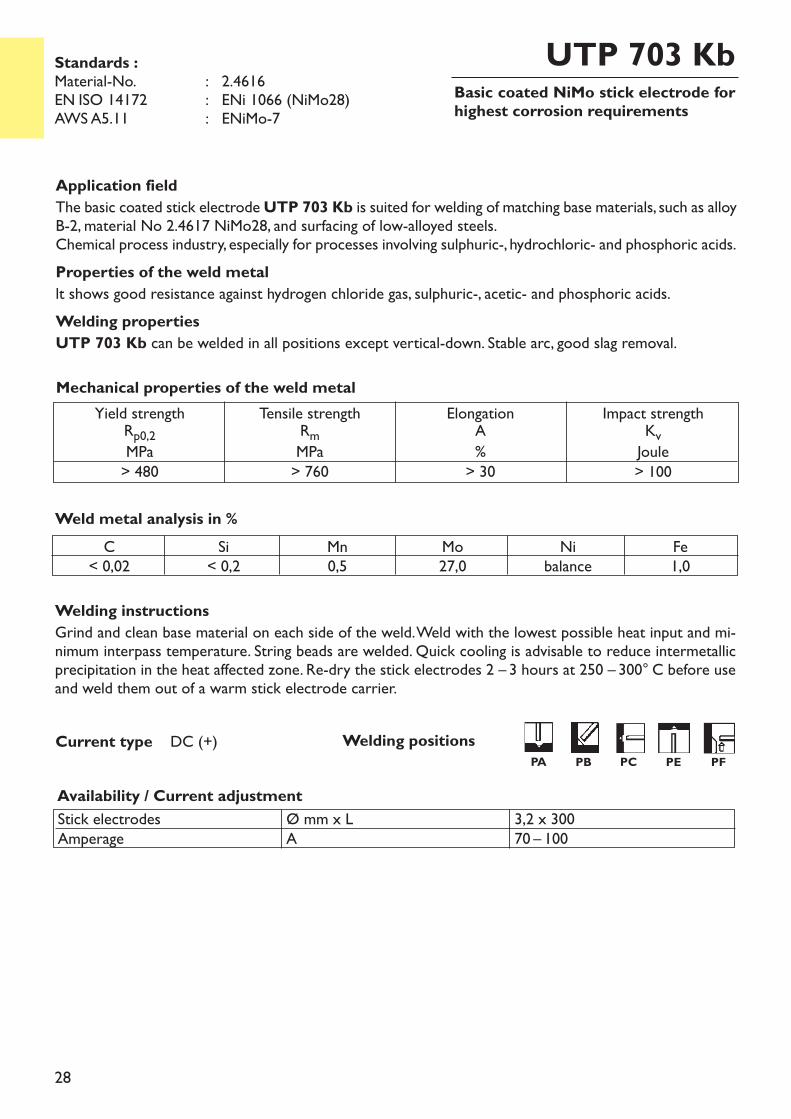
Basic coated NiMo stick electrode forhighest corrosion requirements
UTP 703 Kb
Welding instructionsGrind and clean base material on each side of the weld. Weld with the lowest possible heat input and mi-nimum interpass temperature. String beads are welded. Quick cooling is advisable to reduce intermetallicprecipitation in the heat affected zone. Re-dry the stick electrodes 2 – 3 hours at 250 – 300° C before useand weld them out of a warm stick electrode carrier.
Application fieldThe basic coated stick electrode UTP 703 Kb is suited for welding of matching base materials, such as alloyB-2, material No 2.4617 NiMo28, and surfacing of low-alloyed steels. Chemical process industry, especially for processes involving sulphuric-, hydrochloric- and phosphoric acids.Properties of the weld metallt shows good resistance against hydrogen chloride gas, sulphuric-, acetic- and phosphoric acids.Welding propertiesUTP 703 Kb can be welded in all positions except vertical-down. Stable arc, good slag removal.
Weld metal analysis in %
Yield strengthRp0,2MPa> 480
Tensile strengthRmMPa> 760
ElongationA%> 30
Impact strengthKvJoule> 100
Mechanical properties of the weld metal
Current type DC (+)
Availability / Current adjustmentStick electrodesAmperage
Ø mm x LA
3,2 x 30070 – 100
Standards :Material-No. : 2.4616EN ISO 14172 : ENi 1066 (NiMo28)AWS A5.11 : ENiMo-7
C< 0,02
Si< 0,2
Mn0,5
Mo27,0
Nibalance
Fe1,0
Welding positionsPA PB PC PE PF
29
Basic coated NiMo stick electrode forhighest corrosion requirements
UTP 6202 Mo
Welding instructionsGrind and clean base material on each side of the weld. Weld with the lowest possible heat input and mi-nimum interpass temperature. String beads are welded. Quick cooling is advisable to reduce intermetallicprecipitation in the heat affected zone. Re-dry the stick electrodes 2 – 3 hours at 250 – 300° C before useand weld them out of a warm electrode carrier.
Current type DC (+)
Application fieldUTP 6202 Mo is suited for joining materials of the same nature, e. g. alloy B 3 (UNS 10629, NiMo29Cr,material-No. 2.4600), alloy B 2 (NiMo28, Material-No. 2.4617) or other NiMo-alloys with similar chemicalcomposition such as for surfacing on low alloyed steels.UTP 6202 Mo is used in the chemical process industry, especially for processes involving sulphuric-, hy-drochloric- and phosphoric acid.Properties of the weld metalGood resistance against hydrogen chloride, sulphuric -, acetic - and phosphoric acids. Intermetallic precipi-tation will be largely avoided.
Weld metal analysis in %
Stick electrodesAmperage
Ø mm x LA
2,5 x 30050 – 70
3,2 x 30070 – 90
4,0 x 35090 – 120
Yield strengthReMPa> 450
Tensile strengthRmMPa> 700
ElongationA%> 30
Impact strengthKvJoule> 80
Mechanical properties of the weld metal
Standards :EN ISO 14172 : E Ni 1069
(NiMo28Fe4Cr)AWS A5.11 : E NiMo-11
C Si Mn P S Cr Mo Ni Nb Co Al Fe0,01 0,2 0,5 0,015 0,015 1,0 27,5 balance < 0,5 < 0,5 < 0,5 3,0
Availability / Current adjustment
Welding positionsPA PB PC PE PF
30
Basic coated NiMo-stick electrode for highest corrosion requirements
UTP 6208 Mo
Welding instructionsGrind and clean base material on each side of the weld. Weld with the lowest possible heat input and mi-nimum interpass temperature. String beads are welded. Quick cooling is advisable to reduce intermetallicprecipitation in the heat affected zone. Re-dry the stick electrodes 2 – 3 hours at 250 – 300° C before useand weld them out of a warm electrode carrier.
Current type DC (+)
Application fieldUTP 6208 Mo is suited for joining materials of the same nature, e. g. NiMo23Cr8Fe (Nimofer 6224) AlloyB 10 UNS 10624 or other NiMo-alloys with similar chemical composition such as for surfacing on low al-loyed steels.UTP 6208 Mo is used in the chemical process industry, especially for processes involving sulphuric-, hy-drochloric- and phosphoric acid.Properties of the weld metalGood resistance against hydrogen chloride, sulphuric -, acetic - and phosphoric acids. Intermetallic precipi-tation will be largely avoided UTP 6208 Mo can be welded in all positions except vertical-down. It has a stable arc and easy slag removal.The seam is finely rippled and notch-free.
Stick electrodesAmperage
Ø mm x LA
2,5 x 30050 – 70
3,2 x 30070 – 90
4,0 x 35090 – 120
Weld metal analysis in %
Yield strengthRp0,2MPa> 450
Tensile strengthRmMPa> 700
ElongationA%> 30
Impact strengthKvJoule> 80
Mechanical properties of the weld metal
Standards :EN ISO 14172 : E Ni 1062
(NiMo24Cr8Fe6)
C Si Mn P S Cr Mo Ni Nb Co Al Fe0,01 0,2 0,5 0,015 0,015 7,0 24,0 balance < 0,5 < 0,5 < 0,5 5,5
Availability / Current adjustment
Welding positionsPA PB PC PE PF
31
Fully austenitic rods and wires for cor-rosion resistant steels
UTP A 3127 LC
Application fieldUTP A 3127 LC is suited for joining and surfacing base materials of the same and similar natures, e. g.
1.4500 G- X 7 NiCrMoCuNb 25 201.4505 X 5 NiCrMoCuNb 20 181.4506 X 5 NiCrMoCuTi 20 181.4539 X 2 NiCrMoCu 25 20 51.4563 X 1 NiCrMoCu 31 372.4858 NiCr21Mo
Properties of the weld metalUTP A 3127 LC distinguishes itself by its high resistance against phosphoric acid and organic acids. Dueto its Mo- and Cu-content it shows extremely low corrosion rates, particularly when used in sulphuricacid.Resistant against stress corrosion cracking, crevice corrosion and pitting in media containing chloride ions.
Weld metal analysis in %C
< 0,02Si< 0,2
Mn1,5
Cr27,0
Ni31,0
Mo3,5
Cu1,0
Febalance
Yield strengthRp0,2MPa> 350
Tensile strengthRmMPa> 540
ElongationA%> 30
Impact strengthKvJoule> 80
Mechanical properties of the weld metal
Standards :Material-No.. : 1.4563EN ISO 14343-A : W/G 27 31 4 Cu LAWS A5.9 : ER 383
ApprovalsTÜV (No. 06609)
Ø(mm) Current type Shielding gas
EN ISO 14175Availability
Spools RodsI 1 M 12 EN ISO 544 EN ISO 544
1,2 DC (+) x x2,0 DC (-) x x2,4 DC (-) x x
Welding instructionThe welding area has to be free from inpurities (oil, paint, markings). Minimize heat input. The interpasstemperature should not exceed 150 °C.
Welding procedure and availability
Welding instructionThe welding area has to be free from inpurities (oil, paint, markings). Minimize heat input. The interpasstemperature should not exceed 120 °C. Linear energy input < 8
32
Rods for high corrosion resistant Ni-FeCrMo-alloys
UTP A 3128 Mo
Application fieldUTP A 3128 Mo is suitable for welding of NiFeCrMo-alloys for construction of phosphoric - and sulp-huric acid plants.
1.4562 X 1 NiCrMoCu 32 28 71.4563 X 1 NiCrMoCu 31 27 4
Properties of the weld metalThe weld metal has a good resistance to pitting, crevice corrosion, intercrystalline corrosion and stresscorrosion cracking in oxidizing media containing chloride ions.
Weld metal analysis in %
Yield strengthRp0,2MPa> 450
Tensile strengthRmMPa> 700
ElongationA%> 35
Impact strengthKvJoule> 120
Mechanical properties of the weld metal
Standards :Material-No. : 1.4562EN ISO 14343-A : W/GZ 28327 CuL
C Si Mn P S Cr Mo Ni N Cu Fe0,01 0,1 1,6 < 0,015 < 0,01 27,0 6,5 32,0 0,2 1,2 balance
ApprovalsTÜV (No. 06999)
Welding procedure and availability
Ø(mm) Current type Shielding gas
EN ISO 14175AvailabilityRods
I 1 L (mm)2,0 DC (-) x 10002,4 DC (-) x 1000
kJcm
33
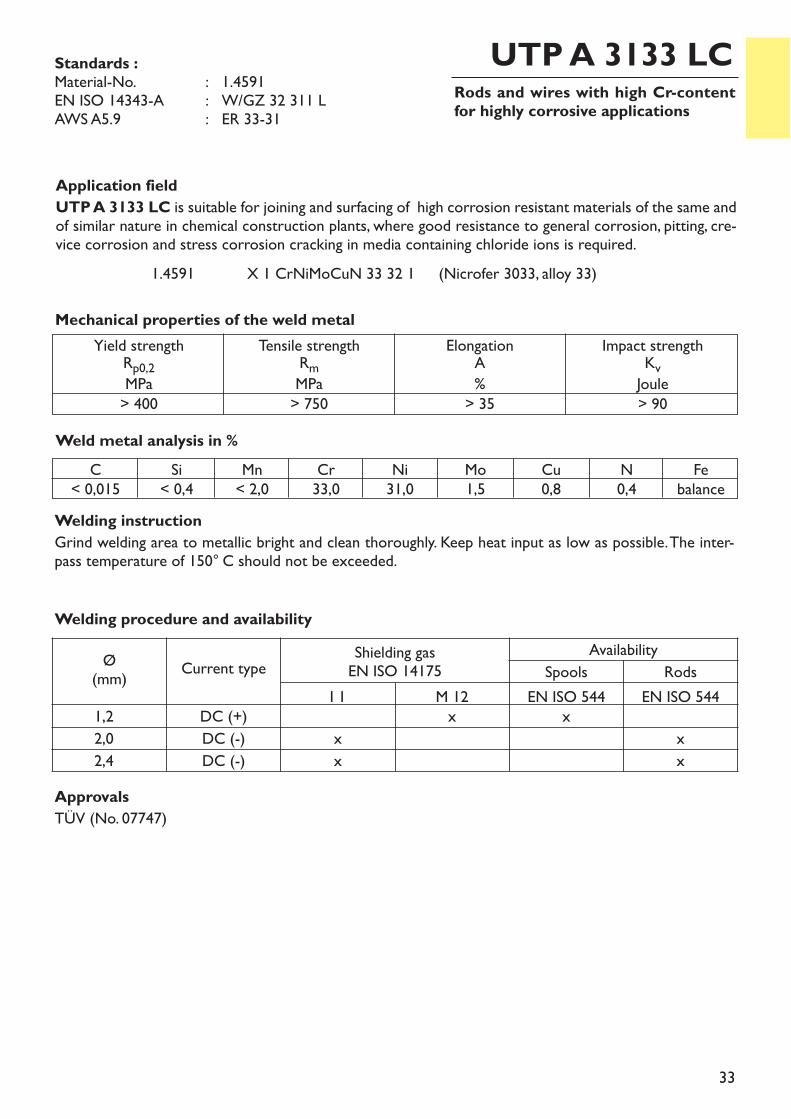
Rods and wires with high Cr-contentfor highly corrosive applications
UTP A 3133 LC
Application fieldUTP A 3133 LC is suitable for joining and surfacing of high corrosion resistant materials of the same andof similar nature in chemical construction plants, where good resistance to general corrosion, pitting, cre-vice corrosion and stress corrosion cracking in media containing chloride ions is required.
1.4591 X 1 CrNiMoCuN 33 32 1 (Nicrofer 3033, alloy 33)
Welding instructionGrind welding area to metallic bright and clean thoroughly. Keep heat input as low as possible. The inter-pass temperature of 150° C should not be exceeded.
Weld metal analysis in %
Yield strengthRp0,2MPa> 400
Tensile strengthRmMPa> 750
ElongationA%> 35
Impact strengthKvJoule> 90
Mechanical properties of the weld metal
Standards :Material-No. : 1.4591EN ISO 14343-A : W/GZ 32 311 LAWS A5.9 : ER 33-31
C< 0,015
Si< 0,4
Mn< 2,0
Cr33,0
Ni31,0
Mo1,5
Cu0,8
N0,4
Febalance
ApprovalsTÜV (No. 07747)
Welding procedure and availability
Ø(mm) Current type Shielding gas
EN ISO 14175Availability
Spools RodsI 1 M 12 EN ISO 544 EN ISO 544
1,2 DC (+) x x2,0 DC (-) x x2,4 DC (-) x x
34
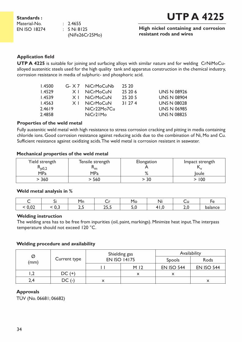
High nickel containing and corrosionresistant rods and wires
UTP A 4225
Application fieldUTP A 4225 is suitable for joining and surfacing alloys with similar nature and for welding CrNiMoCu-alloyed austenitic steels used for the high quality tank and apparatus construction in the chemical industry,corrosion resistance in media of sulphuric- and phosphoric acid.
1.4500 G- X 7 NiCrMoCuNb 25 201.4529 X 1 NiCrMoCuN 25 20 6 UNS N 089261.4539 X 1 NiCrMoCuN 25 20 5 UNS N 089041.4563 X 1 NiCrMoCuN 31 27 4 UNS N 080282.4619 NiCr22Mo7Cu UNS N 069852.4858 NiCr21Mo UNS N 08825
Properties of the weld metalFully austenitic weld metal with high resistance to stress corrosion cracking and pitting in media containingchloride ions. Good corrosion resistance against reducing acids due to the combination of Ni, Mo and Cu.Sufficient resistance against oxidizing acids. The weld metal is corrosion resistant in seawater.
Weld metal analysis in %
Yield strengthRp0,2MPa> 360
Tensile strengthRmMPa> 560
ElongationA%> 30
Impact strengthKvJoule> 100
Mechanical properties of the weld metal
Standards :Material-No. : 2.4655EN ISO 18274 : S Ni 8125
(NiFe26Cr25Mo)
C< 0,02
Si< 0,3
Mn2,5
Cr25,5
Mo5,0
Ni41,0
Cu2,0
Febalance
Welding instructionThe welding area has to be free from inpurities (oil, paint, markings). Minimize heat input. The interpasstemperature should not exceed 120 °C.
ApprovalsTÜV (No. 06681; 06682)
Welding procedure and availability
Ø(mm) Current type Shielding gas
EN ISO 14175Availability
Spools RodsI 1 M 12 EN ISO 544 EN ISO 544
1,2 DC (+) x x2,4 DC (-) x x
35
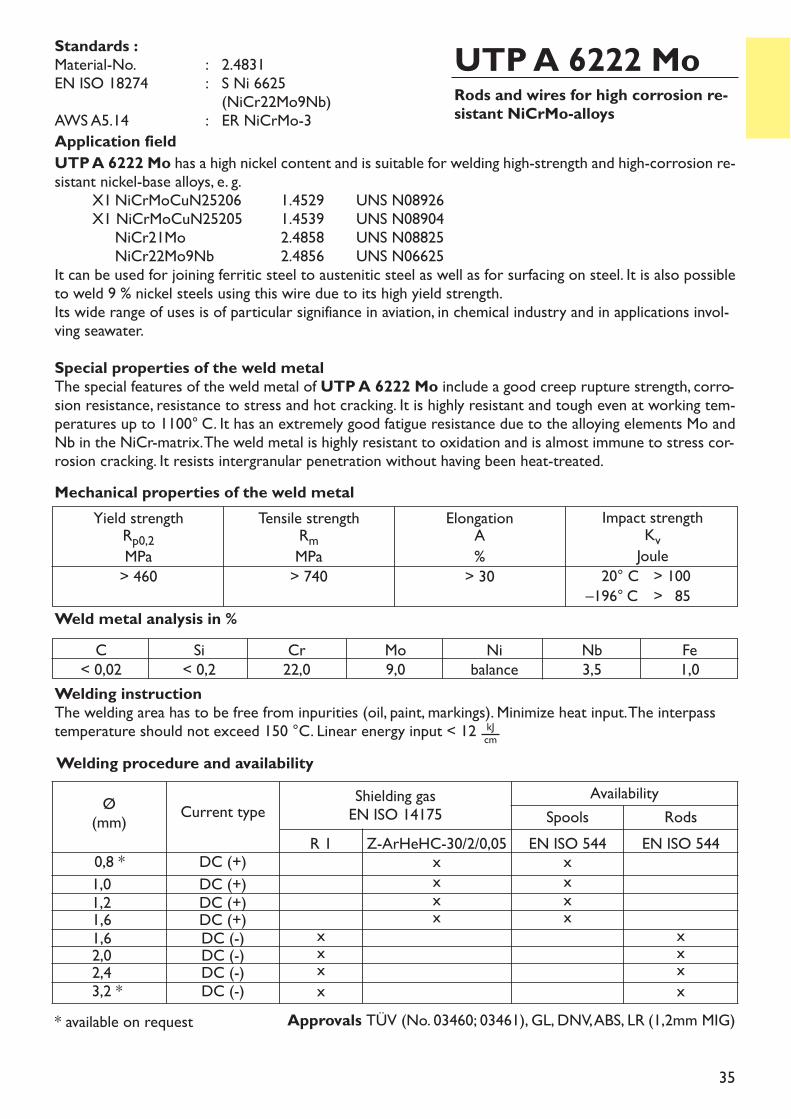
Rods and wires for high corrosion re-sistant NiCrMo-alloys
UTP A 6222 MoApplication fieldUTP A 6222 Mo has a high nickel content and is suitable for welding high-strength and high-corrosion re-sistant nickel-base alloys, e. g.
X1 NiCrMoCuN25206 1.4529 UNS N08926X1 NiCrMoCuN25205 1.4539 UNS N08904NiCr21Mo 2.4858 UNS N08825NiCr22Mo9Nb 2.4856 UNS N06625
It can be used for joining ferritic steel to austenitic steel as well as for surfacing on steel. It is also possibleto weld 9 % nickel steels using this wire due to its high yield strength. Its wide range of uses is of particular signifiance in aviation, in chemical industry and in applications invol-ving seawater.Special properties of the weld metalThe special features of the weld metal of UTP A 6222 Mo include a good creep rupture strength, corro-sion resistance, resistance to stress and hot cracking. It is highly resistant and tough even at working tem-peratures up to 1100° C. It has an extremely good fatigue resistance due to the alloying elements Mo andNb in the NiCr-matrix. The weld metal is highly resistant to oxidation and is almost immune to stress cor-rosion cracking. It resists intergranular penetration without having been heat-treated.
Weld metal analysis in %
Yield strengthRp0,2MPa> 460
Tensile strengthRmMPa> 740
ElongationA%> 30
Impact strengthKvJoule– 20° C > 100–196° C > 85
Mechanical properties of the weld metal
Standards :Material-No. : 2.4831EN ISO 18274 : S Ni 6625
(NiCr22Mo9Nb)AWS A5.14 : ER NiCrMo-3
C< 0,02
Si< 0,2
Cr22,0
Mo9,0
Nibalance
Nb3,5
Fe1,0
Approvals TÜV (No. 03460; 03461), GL, DNV, ABS, LR (1,2mm MIG)
Welding procedure and availability
Ø(mm) Current type Shielding gas
EN ISO 14175Availability
Spools RodsR 1 Z-ArHeHC-30/2/0,05 EN ISO 544 EN ISO 544
0,8 * DC (+) x x1,0 DC (+) x x1,2 DC (+) x x1,6 DC (+) x x1,6 DC (-) x x2,0 DC (-) x x2,4 DC (-) x x3,2 * DC (-) x x
* available on request
Welding instructionThe welding area has to be free from inpurities (oil, paint, markings). Minimize heat input. The interpasstemperature should not exceed 150 °C. Linear energy input < 12 kJ
cm
36
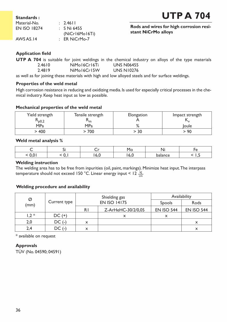
Rods and wires for high corrosion resi-stant NiCrMo alloys
UTP A 704
Application fieldUTP A 704 is suitable for joint weldings in the chemical industry on alloys of the type materials
2.4610 NiMo16Cr16Ti UNS N064552.4819 NiMo16Cr15W UNS N10276
as well as for joining these materials with high and low alloyed steels and for surface weldings.Properties of the weld metalHigh corrosion resistance in reducing and oxidizing media. Is used for especially critical processes in the che-mical industry. Keep heat input as low as possible.
Weld metal analysis %
Yield strengthRp0,2MPa> 400
Tensile strengthRmMPa> 700
ElongationA%> 30
Impact strengthKvJoule> 90
Mechanical properties of the weld metal
Standards :Material-No. : 2.4611EN ISO 18274 : S Ni 6455
(NiCr16Mo16Ti)AWS A5.14 : ER NiCrMo-7
C< 0,01
Si< 0,1
Cr16,0
Mo16,0
Nibalance
Fe< 1,5
ApprovalsTÜV (No. 04590; 04591)
Welding procedure and availability
Ø(mm) Current type Shielding gas
EN ISO 14175Availability
Spools RodsR1 Z-ArHeHC-30/2/0,05 EN ISO 544 EN ISO 544
1,2 * DC (+) x x2,0 DC (-) x x2,4 DC (-) x x
* available on request
Welding instructionThe welding area has to be free from inpurities (oil, paint, markings). Minimize heat input. The interpasstemperature should not exceed 150 °C. Linear energy input < 12 kJ
cm

37
Rods and wires for high corrosion resi-stant NiCrMo alloys
UTP A 776
Application fieldUTP A 776 is suitable for joint welding of matching base materials, as
2.4819 NiMo16Cr15W UNS N10276and surface weldings on low-alloyed steels.UTP A 776 is employed primarily for welding components in plants for chemical processes with highly cor-rosive media, but also for surfacing press tools, punches, etc. which operate at high temperature.Special properties of the weld metalExcellent resistance against sulphuric acids at high chloride concentrations.
Weld metal analysis in %
Yield strengthRp0,2MPa> 450
Tensile strengthRmMPa> 750
ElongationA%> 30
Impact strengthKvJoule> 90
Mechanical properties of the weld metal
Standards :Material-No. : 2.4886EN ISO 18274 : S Ni 6276
(NiCr15Mo16Fe6W4)AWS A5.14 : ER NiCrMo-4
C< 0,01
Si0,07
Cr16,0
Mo16,0
Nibalance
V0,2
W3,5
Fe6,0
ApprovalsTÜV (No. 05586; 05587)
Welding instructionTo avoid intermetallic precipitations, stick electrodes should be welded with lowest possible heat inputand interpass temperature.Welding procedure and availability
Ø(mm) Current type Shielding gas
EN ISO 14175Availability
Spools RodsR 1 Z-ArHeHC-30/2/0,05 EN ISO 544 EN ISO 544
0,8 DC (+) x x1,0 DC (+) x x1,2 DC (+) x x1,6 DC (-) x x2,0 DC (-) x x2,4 DC (-) x x3,2 DC (-) x x
38
Rods and wires for high corrosion resi-stant NiCrMo alloys
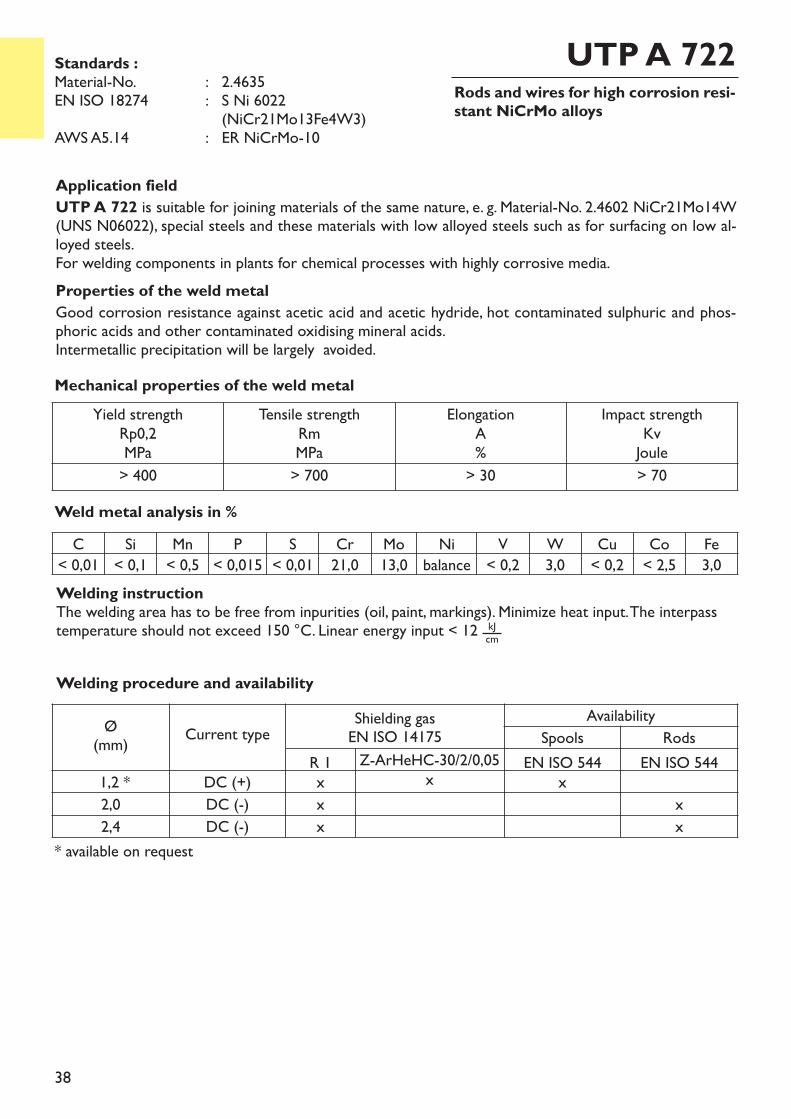
UTP A 722
Application fieldUTP A 722 is suitable for joining materials of the same nature, e. g. Material-No. 2.4602 NiCr21Mo14W(UNS N06022), special steels and these materials with low alloyed steels such as for surfacing on low al-loyed steels.For welding components in plants for chemical processes with highly corrosive media.Properties of the weld metalGood corrosion resistance against acetic acid and acetic hydride, hot contaminated sulphuric and phos-phoric acids and other contaminated oxidising mineral acids.Intermetallic precipitation will be largely avoided.
Weld metal analysis in %
Standards :Material-No. : 2.4635EN ISO 18274 : S Ni 6022
(NiCr21Mo13Fe4W3)AWS A5.14 : ER NiCrMo-10
C Si Mn P S Cr Mo Ni V W Cu Co Fe< 0,01 < 0,1 < 0,5 < 0,015 < 0,01 21,0 13,0 balance < 0,2 3,0 < 0,2 < 2,5 3,0
Welding procedure and availability
Ø(mm) Current type Shielding gas
EN ISO 14175Availability
Spools RodsR 1 Z-ArHeHC-30/2/0,05 EN ISO 544 EN ISO 544
1,2 * DC (+) x x x2,0 DC (-) x x2,4 DC (-) x x
Yield strengthRp0,2MPa
Tensile strengthRmMPa
ElongationA%
Impact strengthKvJoule
> 400 > 700 > 30 > 70
* available on request
Mechanical properties of the weld metal
Welding instructionThe welding area has to be free from inpurities (oil, paint, markings). Minimize heat input. The interpasstemperature should not exceed 150 °C. Linear energy input < 12 kJ
cm
39
Rods and wires for high corrosion resi-stant NiCrMo alloys
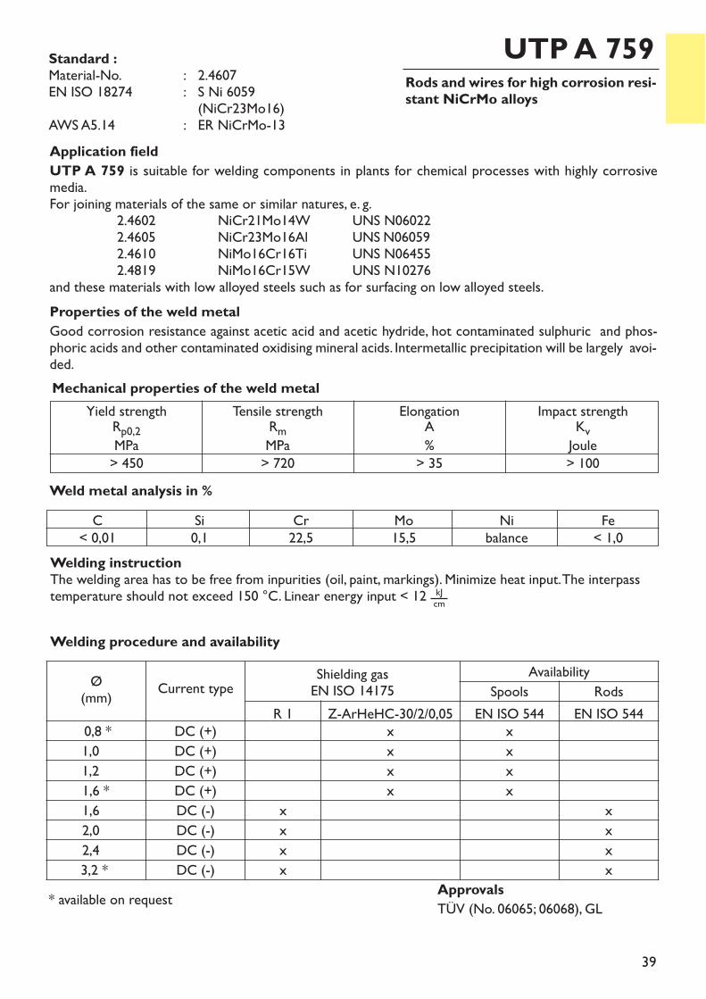
UTP A 759
Application fieldUTP A 759 is suitable for welding components in plants for chemical processes with highly corrosivemedia.For joining materials of the same or similar natures, e. g.
2.4602 NiCr21Mo14W UNS N06022 2.4605 NiCr23Mo16Al UNS N060592.4610 NiMo16Cr16Ti UNS N064552.4819 NiMo16Cr15W UNS N10276
and these materials with low alloyed steels such as for surfacing on low alloyed steels.Properties of the weld metalGood corrosion resistance against acetic acid and acetic hydride, hot contaminated sulphuric and phos-phoric acids and other contaminated oxidising mineral acids. Intermetallic precipitation will be largely avoi-ded.
Weld metal analysis in %
Yield strengthRp0,2MPa> 450
Tensile strengthRmMPa> 720
ElongationA%> 35
Impact strengthKvJoule> 100
Mechanical properties of the weld metal
Standard :Material-No. : 2.4607EN ISO 18274 : S Ni 6059
(NiCr23Mo16)AWS A5.14 : ER NiCrMo-13
ApprovalsTÜV (No. 06065; 06068), GL
C< 0,01
Si0,1
Cr22,5
Mo15,5
Nibalance
Fe< 1,0
Welding procedure and availability
Ø(mm) Current type Shielding gas
EN ISO 14175Availability
Spools RodsR 1 Z-ArHeHC-30/2/0,05 EN ISO 544 EN ISO 544
0,8 * DC (+) x x1,0 DC (+) x x1,2 DC (+) x x1,6 * DC (+) x x1,6 DC (-) x x2,0 DC (-) x x2,4 DC (-) x x3,2 * DC (-) x x
* available on request
Welding instructionThe welding area has to be free from inpurities (oil, paint, markings). Minimize heat input. The interpasstemperature should not exceed 150 °C. Linear energy input < 12 kJ
cm
40
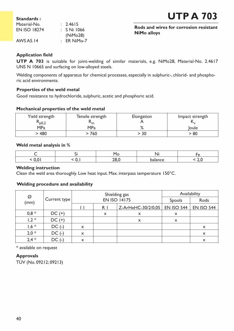
Rods and wires for corrosion resistantNiMo alloys
UTP A 703
Application fieldUTP A 703 is suitable for joint-welding of similar materials, e.g. NiMo28, Material-No. 2.4617 UNS N 10665 and surfacing on low-alloyed steels.Welding components of apparatus for chemical processes, especially in sulphuric-, chlorid- and phospho-ric acid environments.Properties of the weld metalGood resistance to hydrochloride, sulphuric, acetic and phosphoric acid.
Weld metal analysis in %
Yield strengthRp0,2MPa> 480
Tensile strengthRmMPa> 760
ElongationA%> 30
Impact strengthKvJoule> 80
Mechanical properties of the weld metal
Standards :Material-No. : 2.4615EN ISO 18274 : S Ni 1066
(NiMo28)AWS A5.14 : ER NiMo-7
C< 0,01
Si< 0,1
Mo28,0
Nibalance Fe< 2,0
Welding instructionClean the weld area thoroughly. Low heat input. Max. interpass temperature 150°C.Welding procedure and availability
Ø(mm) Current type Shielding gas
EN ISO 14175Availability
Spools RodsI 1 R 1 Z-ArHeHC-30/2/0,05 EN ISO 544 EN ISO 544
0,8 * DC (+) x x x1,2 * DC (+) x x1,6 * DC (-) x x2,0 * DC (-) x x2,4 * DC (-) x x
ApprovalsTÜV (No. 09212; 09213)
* available on request
41
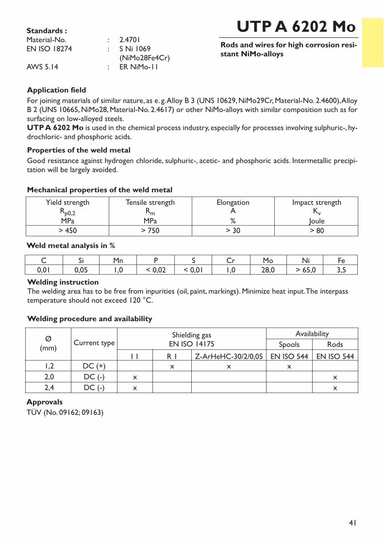
Rods and wires for high corrosion resi-stant NiMo-alloys
UTP A 6202 Mo
Application fieldFor joining materials of similar nature, as e. g. Alloy B 3 (UNS 10629, NiMo29Cr, Material-No. 2.4600), AlloyB 2 (UNS 10665, NiMo28, Material-No. 2.4617) or other NiMo-alloys with similar composition such as forsurfacing on low-alloyed steels.UTP A 6202 Mo is used in the chemical process industry, especially for processes involving sulphuric-, hy-drochloric- and phosphoric acids.Properties of the weld metalGood resistance against hydrogen chloride, sulphuric-, acetic- and phosphoric acids. Intermetallic precipi-tation will be largely avoided.
Weld metal analysis in %
Yield strengthRp0,2MPa> 450
Tensile strengthRmMPa> 750
ElongationA%> 30
Impact strengthKvJoule> 80
Mechanical properties of the weld metal
Standards :Material-No. : 2.4701EN ISO 18274 : S Ni 1069
(NiMo28Fe4Cr)AWS 5.14 : ER NiMo-11
ApprovalsTÜV (No. 09162; 09163)
C0,01
Si0,05
Mn1,0
P< 0,02
S< 0,01
Cr1,0
Mo28,0
Ni> 65,0
Fe3,5
Welding procedure and availability
Ø(mm) Current type Shielding gas
EN ISO 14175Availability
Spools RodsI 1 R 1 Z-ArHeHC-30/2/0,05 EN ISO 544 EN ISO 544
1,2 DC (+) x x x2,0 DC (-) x x2,4 DC (-) x x
Welding instructionThe welding area has to be free from inpurities (oil, paint, markings). Minimize heat input. The interpasstemperature should not exceed 120 °C.
42
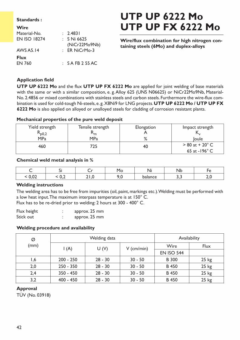
Application fieldUTP UP 6222 Mo and the flux UTP UP FX 6222 Mo are applied for joint welding of base materialswith the same or with a similar composition, e. g. Alloy 625 (UNS N06625) or NiCr22Mo9Nb, Material-No. 2.4856 or mixed combinations with stainless steels and carbon steels. Furthermore the wire-flux com-bination is used for cold-tough Ni-steels, e. g. X8Ni9 for LNG projects. UTP UP 6222 Mo / UTP UP FX6222 Mo is also applied on alloyed or unalloyed steels for cladding of corrosion resistant plants.
Welding instructionsThe welding area has to be free from impurities (oil, paint, markings etc.). Welding must be performed witha low heat input. The maximum interpass temperature is at 150° C.Flux has to be re-dried prior to welding: 2 hours at 300 - 400° C.Flux height : approx. 25 mmStick out : approx. 25 mm
Chemical weld metal analysis in %
Yield strengthRp0,2MPa460
Tensile strengthRmMPa725
ElongationA%40
Impact strengthKvJoule> 80 at + 20° C65 at -196° C
Mechanical properties of the pure weld deposit
Wire/flux combination for high nitrogen con-taining steels (6Mo) and duplex-alloys
UTP UP 6222 MoUTP UP FX 6222 MoStandards :
Wire Material-No. : 2.4831EN ISO 18274 : S Ni 6625
(NiCr22Mo9Nb)AWS A5.14 : ER NiCrMo-3FluxEN 760 : S A FB 2 55 AC
C Si Cr Mo Ni Nb Fe< 0,02 < 0,2 21,0 9,0 balance 3,3 2,0
ApprovalTÜV (No. 03918)
Welding procedure and availabilityØ(mm)
Welding data AvailabilityI (A) U (V) V (cm/min) Wire Flux
EN ISO 5441,6 200 - 250 28 - 30 30 - 50 B 300 25 kg2,0 250 - 350 28 - 30 30 - 50 B 450 25 kg2,4 350 - 450 28 - 30 30 - 50 B 450 25 kg3,2 400 - 450 28 - 30 30 - 50 B 450 25 kg
43
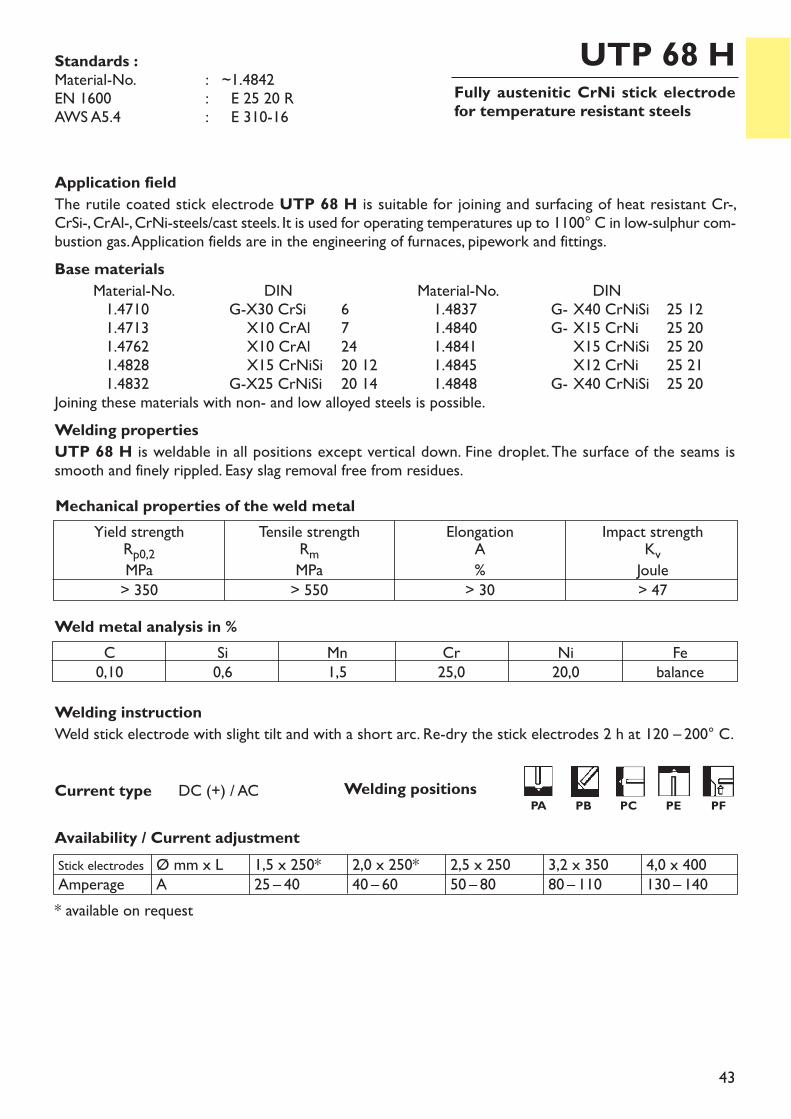
Fully austenitic CrNi stick electrodefor temperature resistant steels
UTP 68 H
Welding instructionWeld stick electrode with slight tilt and with a short arc. Re-dry the stick electrodes 2 h at 120 – 200° C.
Weld metal analysis in %C0,10
Si0,6
Mn1,5
Cr25,0
Ni20,0
Febalance
Current type DC (+) / AC
Application fieldThe rutile coated stick electrode UTP 68 H is suitable for joining and surfacing of heat resistant Cr-, CrSi-, CrAl-, CrNi-steels/cast steels. It is used for operating temperatures up to 1100° C in low-sulphur com-bustion gas. Application fields are in the engineering of furnaces, pipework and fittings.Base materials
Material-No. DIN Material-No. DIN1.4710 G-X30 CrSi 6 1.4837 G- X40 CrNiSi 25 121.4713 X10 CrAl 7 1.4840 G- X15 CrNi 25 201.4762 X10 CrAl 24 1.4841 X15 CrNiSi 25 201.4828 X15 CrNiSi 20 12 1.4845 X12 CrNi 25 211.4832 G-X25 CrNiSi 20 14 1.4848 G- X40 CrNiSi 25 20
Joining these materials with non- and low alloyed steels is possible.Welding propertiesUTP 68 H is weldable in all positions except vertical down. Fine droplet. The surface of the seams issmooth and finely rippled. Easy slag removal free from residues.
* available on request
Stick electrodesAmperage
Ø mm x LA
1,5 x 250*25 – 40
2,0 x 250*40 – 60
2,5 x 25050 – 80
3,2 x 35080 – 110
4,0 x 400130 – 140
Yield strengthRp0,2MPa> 350
Tensile strengthRmMPa> 550
ElongationA%> 30
Impact strengthKvJoule> 47
Mechanical properties of the weld metal
Standards :Material-No. : ~1.4842EN 1600 : ~E 25 20 R AWS A5.4 : ~E 310-16
Availability / Current adjustment
Welding positionsPA PB PC PE PF
44
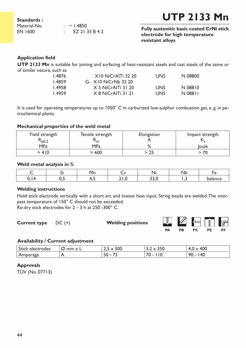
Fully austenitic basic coated CrNi stickelectrode for high temperature resistant alloys
UTP 2133 Mn
Welding instructionsHold stick electrode vertically with a short arc and lowest heat input. String beads are welded. The inter-pass temperature of 150° C should not be exceeded.Re-dry stick electrodes for 2 – 3 h at 250 -300° C.
Current type DC (+)
Application fieldUTP 2133 Mn is suitable for joining and surfacing of heat-resistant steels and cast steels of the same orof similar nature, such as
1.4876 X10 NiCrAlTi 32 20 UNS N 088001.4859 G- X10 NiCrNb 32 201.4958 X 5 NiCrAlTi 31 20 UNS N 088101.4959 X 8 NiCrAlTi 31 21 UNS N 08811
It is used for operating temperatures up to 1050° C in carburized low-sulphur combustion gas, e. g. in pe-trochemical plants.
Weld metal analysis in %C0,14
Si0,5
Mn4,5
Cr21,0
Ni33,0
Nb1,3
Febalance
Availability / Current adjustmentStick electrodesAmperage
Ø mm x LA
2,5 x 30050 – 75
3,2 x 35070 – 110
4,0 x 40090 – 140
Yield strengthRp0,2MPa> 410
Tensile strengthRmMPa> 600
ElongationA%> 25
Impact strengthKvJoule> 70
Mechanical properties of the weld metal
Standards :Material-No. : ~ 1.4850EN 1600 : ~ EZ 21 33 B 4 2
ApprovalsTÜV (No. 07713)
Welding positionsPA PB PC PE PF
45
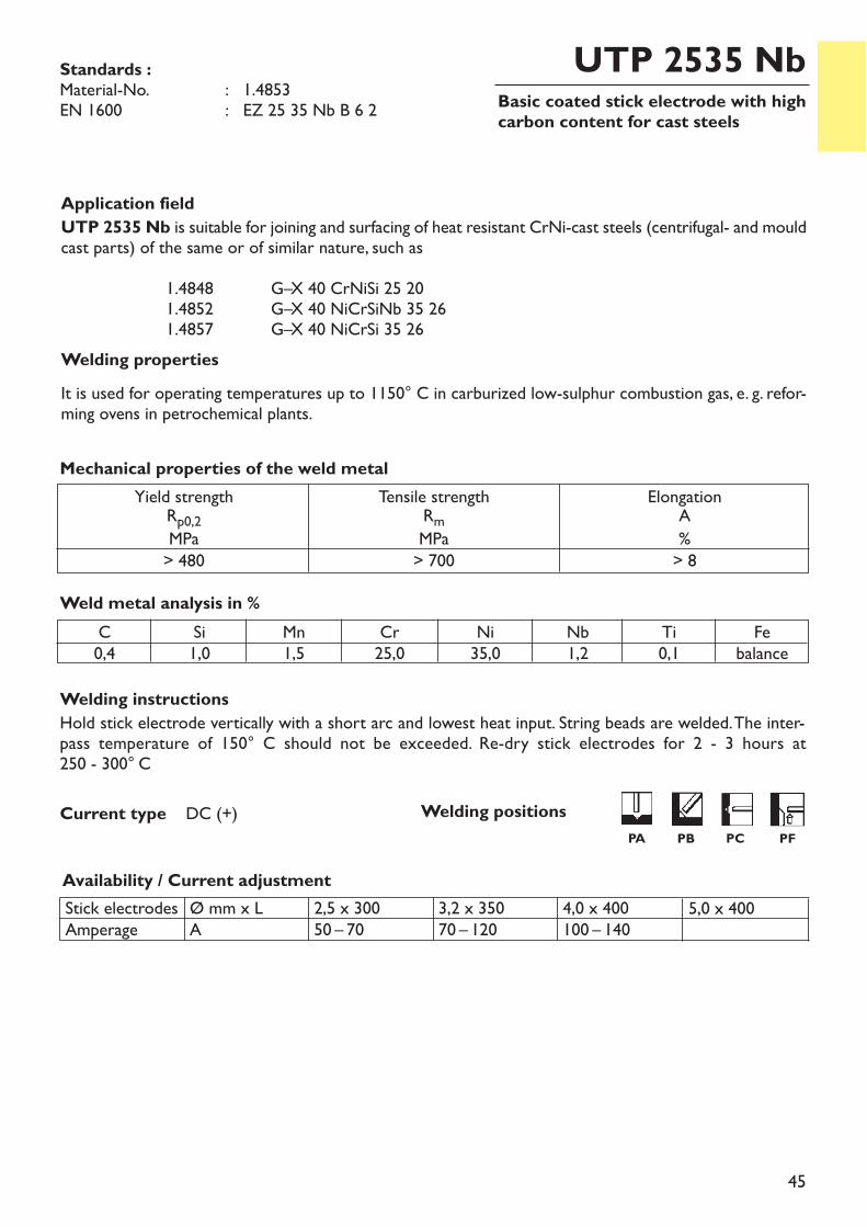
Basic coated stick electrode with highcarbon content for cast steels
UTP 2535 Nb
Welding instructionsHold stick electrode vertically with a short arc and lowest heat input. String beads are welded. The inter-pass temperature of 150° C should not be exceeded. Re-dry stick electrodes for 2 - 3 hours at 250 - 300° C
Current type DC (+)
Application fieldUTP 2535 Nb is suitable for joining and surfacing of heat resistant CrNi-cast steels (centrifugal- and mouldcast parts) of the same or of similar nature, such as
1.4848 G–X 40 CrNiSi 25 201.4852 G–X 40 NiCrSiNb 35 261.4857 G–X 40 NiCrSi 35 26
Welding propertiesIt is used for operating temperatures up to 1150° C in carburized low-sulphur combustion gas, e. g. refor-ming ovens in petrochemical plants.
Weld metal analysis in %C0,4
Si1,0
Mn1,5
Cr25,0
Ni35,0
Nb1,2
Ti0,1
Febalance
Availability / Current adjustmentStick electrodesAmperage
Ø mm x LA
2,5 x 30050 – 70
3,2 x 35070 – 120
4,0 x 400100 – 140
Yield strengthRp0,2MPa> 480
Tensile strengthRmMPa> 700
ElongationA%> 8
Mechanical properties of the weld metal
Standards :Material-No. : 1.4853EN 1600 : EZ 25 35 Nb B 6 2
5,0 x 400
Welding positions PA PB PC PF
46
Basic coated stick electrode for hightemperature cast materials
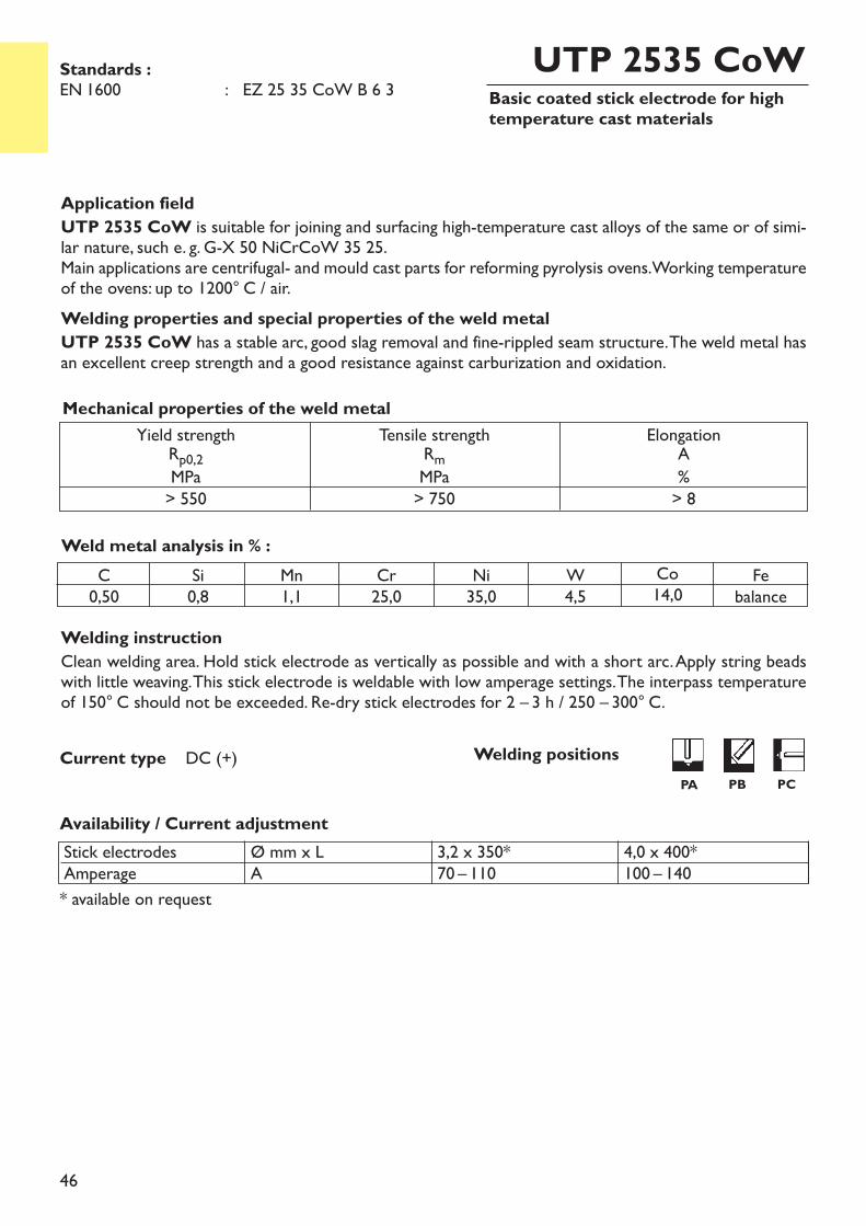
UTP 2535 CoW
Welding instructionClean welding area. Hold stick electrode as vertically as possible and with a short arc. Apply string beadswith little weaving. This stick electrode is weldable with low amperage settings. The interpass temperatureof 150° C should not be exceeded. Re-dry stick electrodes for 2 – 3 h / 250 – 300° C.
Application fieldUTP 2535 CoW is suitable for joining and surfacing high-temperature cast alloys of the same or of simi-lar nature, such e. g. G-X 50 NiCrCoW 35 25.Main applications are centrifugal- and mould cast parts for reforming pyrolysis ovens. Working temperatureof the ovens: up to 1200° C / air.Welding properties and special properties of the weld metalUTP 2535 CoW has a stable arc, good slag removal and fine-rippled seam structure. The weld metal hasan excellent creep strength and a good resistance against carburization and oxidation.
Weld metal analysis in % :
Current type DC (+)
C0,50
Si0,8
Mn1,1
Cr25,0
Ni35,0
Co14,0
W4,5
Febalance
Availability / Current adjustment
* available on request
Yield strengthRp0,2MPa> 550
Tensile strengthRmMPa> 750
ElongationA%> 8
Mechanical properties of the weld metal
Standards :EN 1600 : EZ 25 35 CoW B 6 3
4,0 x 400*100 – 140
Stick electrodesAmperage
Ø mm x LA
3,2 x 350*70 – 110
Welding positionsPA PB PC
47
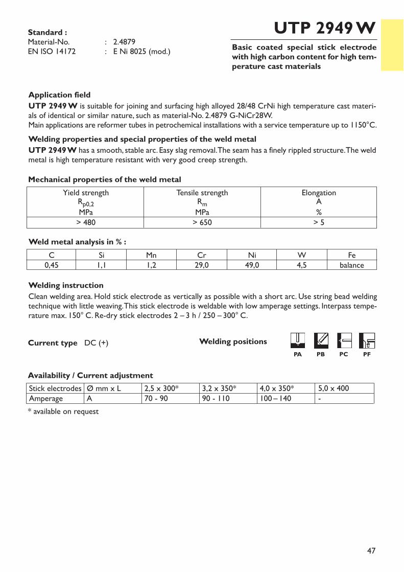
Basic coated special stick electrodewith high carbon content for high tem-perature cast materials
UTP 2949 W
Welding instructionClean welding area. Hold stick electrode as vertically as possible with a short arc. Use string bead weldingtechnique with little weaving. This stick electrode is weldable with low amperage settings. Interpass tempe-rature max. 150° C. Re-dry stick electrodes 2 – 3 h / 250 – 300° C.
Application fieldUTP 2949 W is suitable for joining and surfacing high alloyed 28/48 CrNi high temperature cast materi-als of identical or similar nature, such as material-No. 2.4879 G-NiCr28W.Main applications are reformer tubes in petrochemical installations with a service temperature up to 1150°C. Welding properties and special properties of the weld metalUTP 2949 W has a smooth, stable arc. Easy slag removal. The seam has a finely rippled structure. The weldmetal is high temperature resistant with very good creep strength.
Weld metal analysis in % :
Current type DC (+)
Availability / Current adjustment
C0,45
Si1,1
Mn1,2
Cr29,0
Ni49,0
W4,5
Febalance
Yield strengthRp0,2MPa> 480
Tensile strengthRmMPa> 650
ElongationA%> 5
Mechanical properties of the weld metal
* available on request
Standard :Material-No. : 2.4879EN ISO 14172 : E Ni 8025 (mod.)
Stick electrodesAmperage
Ø mm x LA
2,5 x 300*70 - 90
3,2 x 350*90 - 110
4,0 x 350*100 – 140
5,0 x 400-
Welding positionsPA PB PC PF
48
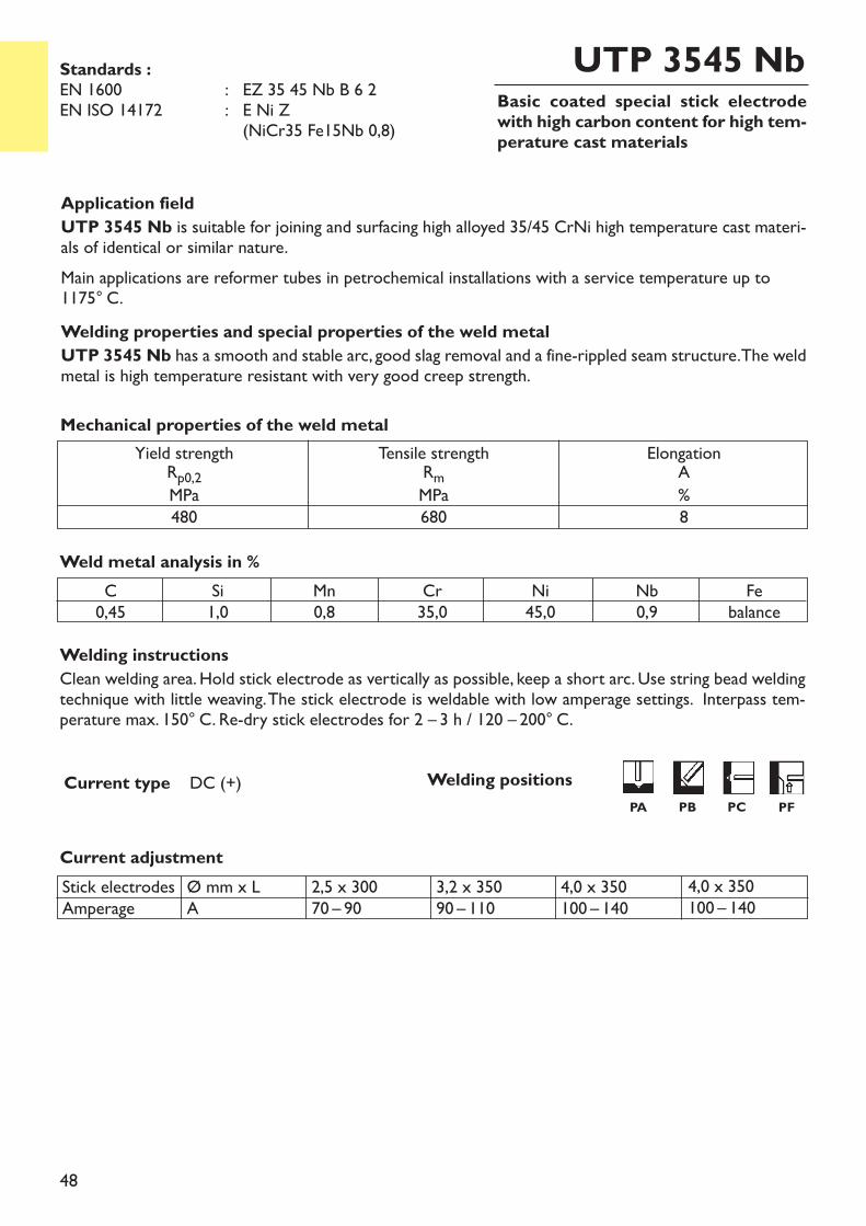
Basic coated special stick electrodewith high carbon content for high tem-perature cast materials
UTP 3545 Nb
Welding instructionsClean welding area. Hold stick electrode as vertically as possible, keep a short arc. Use string bead weldingtechnique with little weaving. The stick electrode is weldable with low amperage settings. Interpass tem-perature max. 150° C. Re-dry stick electrodes for 2 – 3 h / 120 – 200° C.
Current adjustment
Current type DC (+)
Application fieldUTP 3545 Nb is suitable for joining and surfacing high alloyed 35/45 CrNi high temperature cast materi-als of identical or similar nature. Main applications are reformer tubes in petrochemical installations with a service temperature up to1175° C.Welding properties and special properties of the weld metalUTP 3545 Nb has a smooth and stable arc, good slag removal and a fine-rippled seam structure. The weldmetal is high temperature resistant with very good creep strength.
Weld metal analysis in %C0,45
Si1,0
Mn0,8
Cr35,0
Ni45,0
Nb0,9
Febalance
Yield strengthRp0,2MPa480
Tensile strengthRmMPa680
ElongationA%8
Mechanical properties of the weld metal
Standards :EN 1600 : EZ 35 45 Nb B 6 2EN ISO 14172 : E Ni Z
(NiCr35 Fe15Nb 0,8)
4,0 x 350100 – 140
Stick electrodesAmperage
Ø mm x LA
2,5 x 30070 – 90
3,2 x 35090 – 110
4,0 x 350100 – 140
Welding positionsPA PB PC PF
49
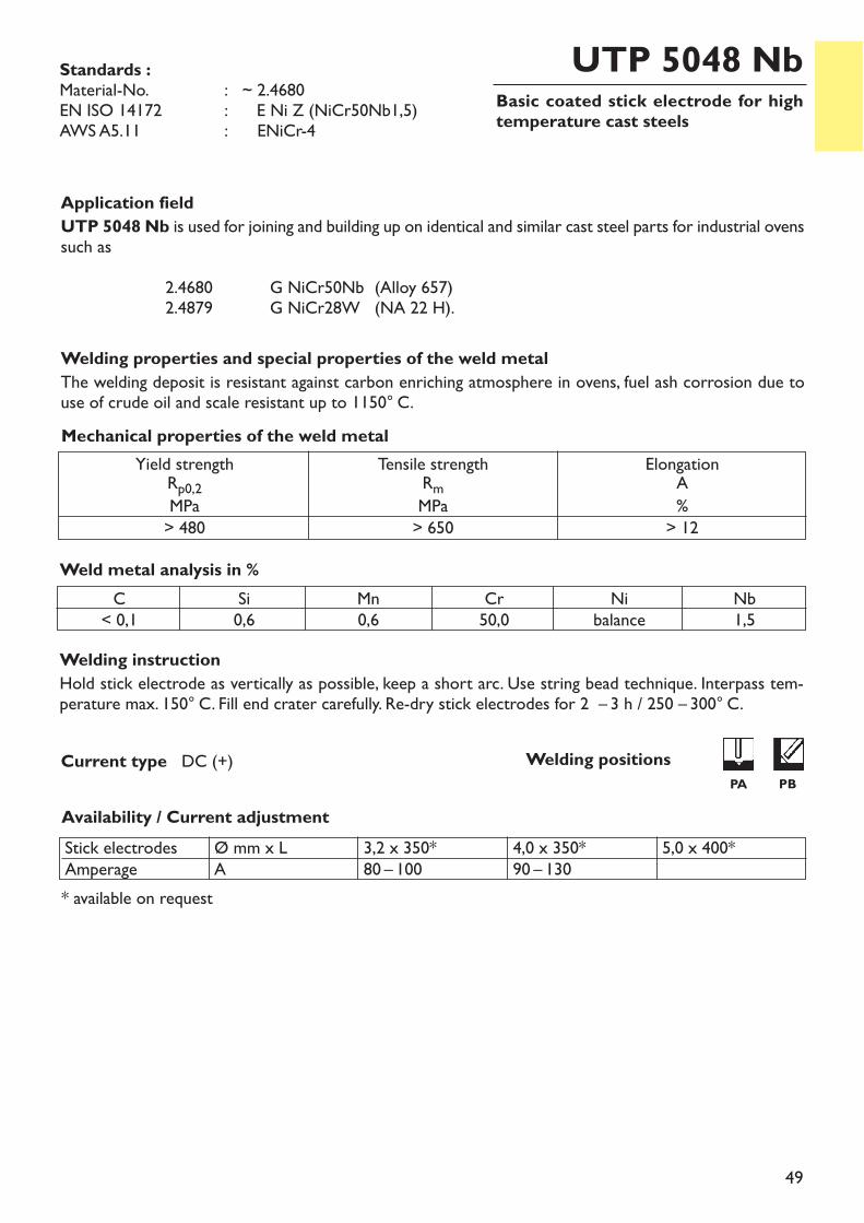
Basic coated stick electrode for hightemperature cast steels
UTP 5048 Nb
Welding instructionHold stick electrode as vertically as possible, keep a short arc. Use string bead technique. Interpass tem-perature max. 150° C. Fill end crater carefully. Re-dry stick electrodes for 2 – 3 h / 250 – 300° C.
Current type DC (+)
Application fieldUTP 5048 Nb is used for joining and building up on identical and similar cast steel parts for industrial ovenssuch as
2.4680 G NiCr50Nb (Alloy 657)2.4879 G NiCr28W (NA 22 H).
Welding properties and special properties of the weld metalThe welding deposit is resistant against carbon enriching atmosphere in ovens, fuel ash corrosion due touse of crude oil and scale resistant up to 1150° C.
Weld metal analysis in %C< 0,1
Si0,6
Mn0,6
Cr50,0
Nb1,5
Nibalance
Availability / Current adjustment
* available on request
Yield strengthRp0,2MPa> 480
Tensile strengthRmMPa> 650
ElongationA%> 12
Mechanical properties of the weld metal
Standards :Material-No. : ~ 2.4680EN ISO 14172 : E Ni Z (NiCr50Nb1,5)AWS A5.11 : ~ ENiCr-4
Stick electrodesAmperage
Ø mm x LA
3,2 x 350*80 – 100
4,0 x 350*90 – 130
5,0 x 400*
Welding positions PA PB
50
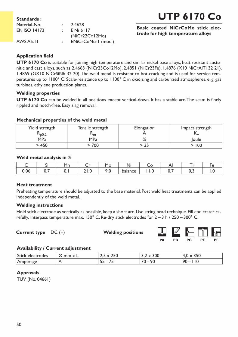
Basic coated NiCrCoMo stick elec-trode for high temperature alloys
UTP 6170 Co
Heat treatmentPreheating temperature should be adjusted to the base material. Post weld heat treatments can be appliedindependently of the weld metal.Welding instructionsHold stick electrode as vertically as possible, keep a short arc. Use string bead technique. Fill end crater ca-refully. Interpass temperature max. 150° C. Re-dry stick electrodes for 2 – 3 h / 250 – 300° C.
Current type DC (+)
Application fieldUTP 6170 Co is suitable for joining high-temperature and similar nickel-base alloys, heat resistant auste-nitic and cast alloys, such as 2.4663 (NiCr23Co12Mo), 2.4851 (NiCr23Fe), 1.4876 (X10 NiCrAlTi 32 21),1.4859 (GX10 NiCrSiNb 32 20). The weld metal is resistant to hot-cracking and is used for service tem-peratures up to 1100° C. Scale-resistance up to 1100° C in oxidizing and carburized atmospheres, e. g. gasturbines, ethylene production plants.Welding propertiesUTP 6170 Co can be welded in all positions except vertical-down. It has a stable arc. The seam is finelyrippled and notch-free. Easy slag removal.
Availability / Current adjustment
Weld metal analysis in %
Stick electrodesAmperage
Ø mm x LA
2,5 x 25055 - 75
3,2 x 30070 – 90
4,0 x 35090 – 110
Yield strengthRp0,2MPa> 450
Tensile strengthRmMPa> 700
ElongationA%> 35
Impact strengthKvJoule> 100
Mechanical properties of the weld metal
Standards :Material-No. : ~ 2.4628EN ISO 14172 : ~ E Ni 6117
~ (NiCr22Co12Mo)AWS A5.11 : ~ ENiCrCoMo-1 (mod.)
C0,06
Si0,7
Mn0,1
Cr21,0
Mo9,0
Nibalance
Co11,0
Al0,7
Ti0,3
Fe1,0
ApprovalsTÜV (No. 04661)
Welding positionsPA PB PC PE PF
51
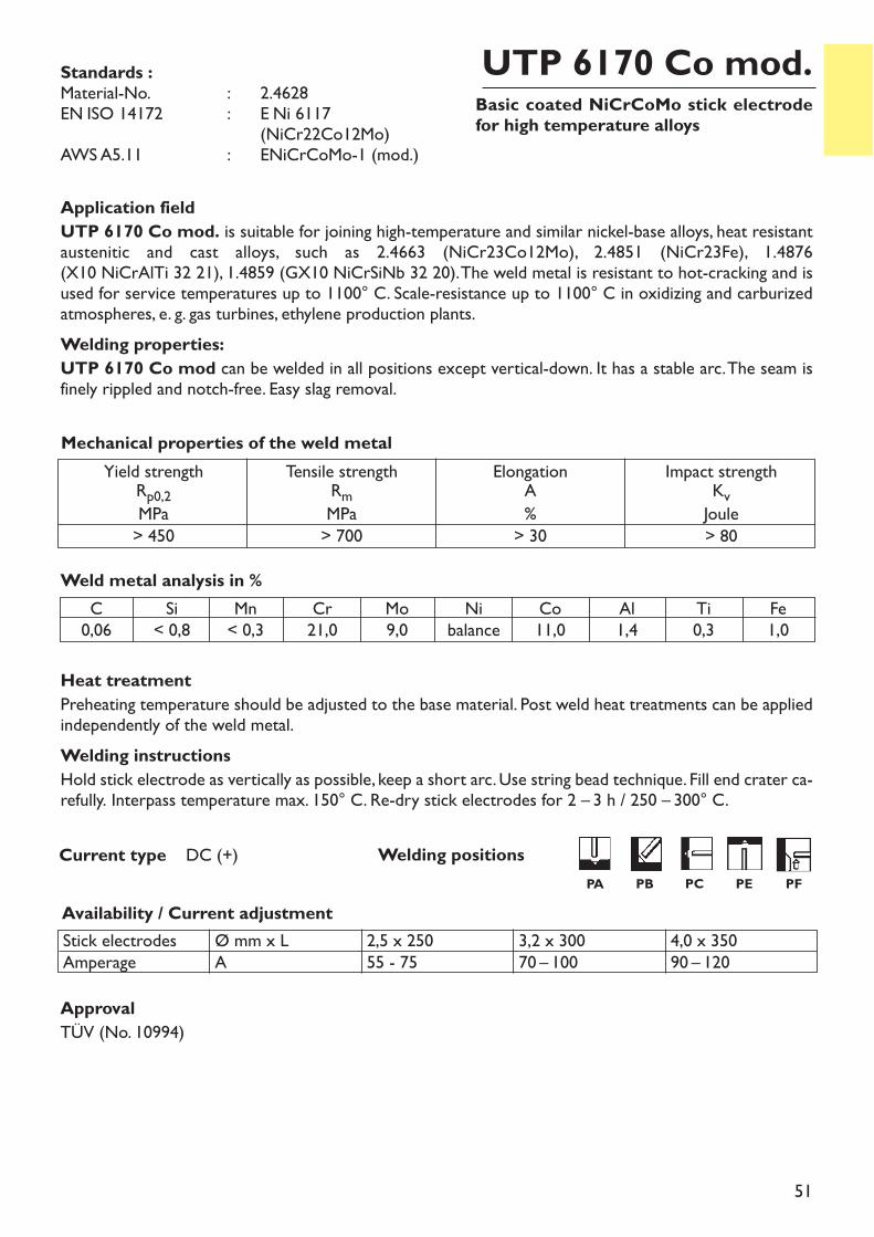
Basic coated NiCrCoMo stick electrodefor high temperature alloys
UTP 6170 Co mod.
Heat treatmentPreheating temperature should be adjusted to the base material. Post weld heat treatments can be appliedindependently of the weld metal.Welding instructionsHold stick electrode as vertically as possible, keep a short arc. Use string bead technique. Fill end crater ca-refully. Interpass temperature max. 150° C. Re-dry stick electrodes for 2 – 3 h / 250 – 300° C.
Current type DC (+)
Application fieldUTP 6170 Co mod. is suitable for joining high-temperature and similar nickel-base alloys, heat resistantaustenitic and cast alloys, such as 2.4663 (NiCr23Co12Mo), 2.4851 (NiCr23Fe), 1.4876 (X10 NiCrAlTi 32 21), 1.4859 (GX10 NiCrSiNb 32 20). The weld metal is resistant to hot-cracking and isused for service temperatures up to 1100° C. Scale-resistance up to 1100° C in oxidizing and carburizedatmospheres, e. g. gas turbines, ethylene production plants.Welding properties:UTP 6170 Co mod can be welded in all positions except vertical-down. It has a stable arc. The seam isfinely rippled and notch-free. Easy slag removal.
Availability / Current adjustment
Weld metal analysis in %
Stick electrodesAmperage
Ø mm x LA
2,5 x 25055 - 75
3,2 x 30070 – 100
4,0 x 35090 – 120
Yield strengthRp0,2MPa> 450
Tensile strengthRmMPa> 700
ElongationA%> 30
Impact strengthKvJoule> 80
Mechanical properties of the weld metal
Standards :Material-No. : ~ 2.4628EN ISO 14172 : ~ E Ni 6117
~ (NiCr22Co12Mo)AWS A5.11 : ~ ENiCrCoMo-1 (mod.)
C0,06
Si< 0,8
Mn< 0,3
Cr21,0
Mo9,0
Nibalance
Co11,0
Al1,4
Ti0,3
Fe1,0
Welding positionsPA PB PC PE PF
ApprovalTÜV (No. 10994)
52
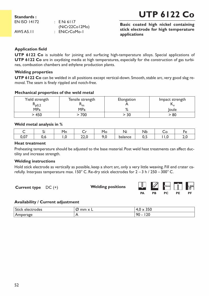
Basic coated high nickel containingstick electrode for high temperatureapplications
UTP 6122 Co
Heat treatmentPreheating temperature should be adjusted to the base material. Post weld heat treatments can affect duc-tility and increase strength.Welding instructionsHold stick electrode as vertically as possible, keep a short arc, only a very little weaving. Fill end crater ca-refully. Interpass temperature max. 150° C. Re-dry stick electrodes for 2 – 3 h / 250 – 300° C.
Current type DC (+)
Application fieldUTP 6122 Co is suitable for joining and surfacing high-temperature alloys. Special applications of UTP 6122 Co are in oxydizing media at high temperatures, especially for the construction of gas turbi-nes, combustion chambers and ethylene production plants.Welding propertiesUTP 6122 Co can be welded in all positions except vertical-down. Smooth, stable arc, very good slag re-moval. The seam is finely rippled and notch-free.
Weld metal analysis in %
Availability / Current adjustment
Yield strengthRp0,2MPa> 450
Tensile strengthRmMPa> 700
ElongationA%> 30
Impact strengthKvJoule> 80
Mechanical properties of the weld metal
Standards :EN ISO 14172 : E Ni 6117
(NiCr22Co12Mo)AWS A5.11 : ENiCrCoMo-1
C0,07
Si0,6
Mn1,0
Cr22,0
Mo9,0
Nibalance
Nb0,5
Co11,0
Fe2,0
Stick electrodesAmperage
Ø mm x LA
4,0 x 35090 - 120
Welding positionsPA PB PC PE PF
53
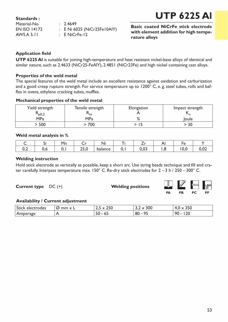
Basic coated NiCrFe stick electrodewith element addition for high tempe-rature alloys
UTP 6225 Al
Welding instructionHold stick electrode as vertically as possible, keep a short arc. Use string beads technique and fill end cra-ter carefully. Interpass temperature max. 150° C. Re-dry stick electrodes for 2 – 3 h / 250 – 300° C.
Current type DC (+)
Application fieldUTP 6225 Al is suitable for joining high-temperature and heat resistant nickel-base alloys of identical andsimilar nature, such as 2.4633 (NiCr25-FeAlY), 2.4851 (NiCr23Fe) and high nickel containing cast alloys.Properties of the weld metalThe special features of the weld metal include an excellent resistance against oxidation and carburizationand a good creep rupture strength. For service temperature up to 1200° C, e. g. steel tubes, rolls and baf-fles in ovens, ethylene cracking tubes, muffles.
Availability / Current adjustment
Weld metal analysis in %
Stick electrodesAmperage
Ø mm x LA
2,5 x 25050 – 65
3,2 x 30080 – 95
4,0 x 35090 – 120
Yield strengthRp0,2MPa> 500
Tensile strengthRmMPa> 700
ElongationA%> 15
Impact strengthKvJoule> 30
Mechanical properties of the weld metal
Standards :Material-No. : 2.4649EN ISO 14172 : E Ni 6025 (NiCr25Fe10AlY)AWS A 5.11 : E NiCrFe-12
C0,2
Si0,6
Mn0,1
Cr25,0
Nibalance
Ti0,1
Zr0,03
Al1,8
Fe10,0
Y0,02
Welding positionsPA PB PC PF
54
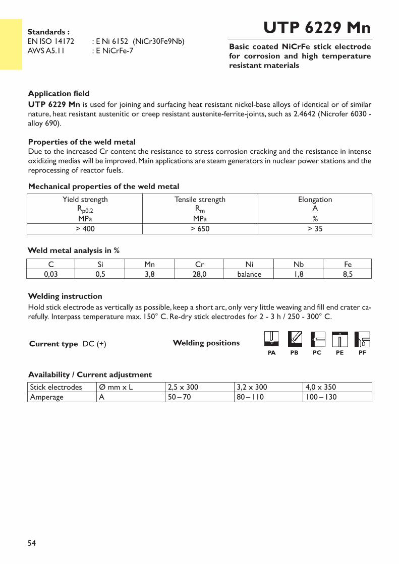
Basic coated NiCrFe stick electrodefor corrosion and high temperatureresistant materials
UTP 6229 Mn
Welding instructionHold stick electrode as vertically as possible, keep a short arc, only very little weaving and fill end crater ca-refully. Interpass temperature max. 150° C. Re-dry stick electrodes for 2 - 3 h / 250 - 300° C.
Current type DC (+)
Application fieldUTP 6229 Mn is used for joining and surfacing heat resistant nickel-base alloys of identical or of similarnature, heat resistant austenitic or creep resistant austenite-ferrite-joints, such as 2.4642 (Nicrofer 6030 -alloy 690). Properties of the weld metalDue to the increased Cr content the resistance to stress corrosion cracking and the resistance in intenseoxidizing medias will be improved. Main applications are steam generators in nuclear power stations and thereprocessing of reactor fuels.
Weld metal analysis in %
Availability / Current adjustmentStick electrodesAmperage
Ø mm x LA
2,5 x 30050 – 70
3,2 x 30080 – 110
4,0 x 350100 – 130
Yield strengthRp0,2MPa> 400
Tensile strengthRmMPa> 650
ElongationA%> 35
Mechanical properties of the weld metal
Standards :EN ISO 14172 : E Ni 6152 (NiCr30Fe9Nb)AWS A5.11 : E NiCrFe-7
C0,03
Si0,5
Mn3,8
Cr28,0
Nibalance
Nb1,8
Fe8,5
Welding positionsPA PB PC PE PF
55
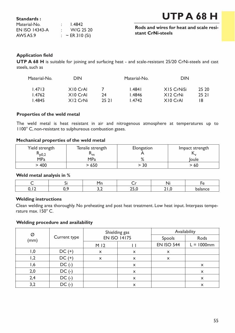
Rods and wires for heat and scale resi-stant CrNi-steels
UTP A 68 H
Application fieldUTP A 68 H is suitable for joining and surfacing heat - and scale-resistant 25/20 CrNi-steels and caststeels, such as
Material-No. DIN Material-No. DIN1.4713 X10 CrAl 7 1.4841 X15 CrNiSi 25 201.4762 X10 CrAl 24 1.4846 X12 CrNi 25 211.4845 X12 CrNi 25 21 1.4742 X10 CrAl 18
Properties of the weld metalThe weld metal is heat resistant in air and nitrogenous atmosphere at temperatures up to 1100° C, non-resistant to sulphureous combustion gases.
Welding instructionsClean welding area thoroughly. No preheating and post heat treatment. Low heat input. Interpass tempe-rature max. 150° C.
Weld metal analysis in %C0,12
Si0,9
Mn3,2
Cr25,0
Ni21,0
Febalance
Yield strengthRp0,2MPa> 400
Tensile strengthRmMPa> 650
ElongationA%> 30
Impact strengthKvJoule> 60
Mechanical properties of the weld metal
Standards :Material-No. : ~ 1.4842EN ISO 14343-A : W/G 25 20AWS A5.9 : ~ ER 310 (Si)
Welding procedure and availability
Ø(mm) Current type Shielding gas
EN ISO 14175Availability
Spools RodsM 12 I 1 EN ISO 544 L = 1000mm
1,0 DC (+) x x x1,2 DC (+) x x x1,6 DC (-) x x2,0 DC (-) x x2,4 DC (-) x x3,2 DC (-) x x
56
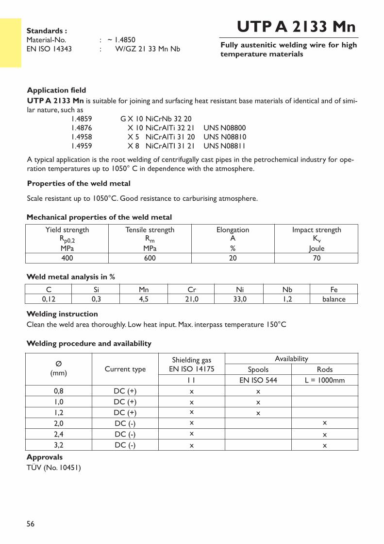
Fully austenitic welding wire for hightemperature materials
UTP A 2133 Mn
Application fieldUTP A 2133 Mn is suitable for joining and surfacing heat resistant base materials of identical and of simi-lar nature, such as
1.4859 G X 10 NiCrNb 32 201.4876 X 10 NiCrAlTi 32 21 UNS N088001.4958 X 5 NiCrAlTi 31 20 UNS N088101.4959 X 8 NiCrAlTI 31 21 UNS N08811
A typical application is the root welding of centrifugally cast pipes in the petrochemical industry for ope-ration temperatures up to 1050° C in dependence with the atmosphere.Properties of the weld metalScale resistant up to 1050°C. Good resistance to carburising atmosphere.
Weld metal analysis in %C0,12
Si0,3
Mn4,5
Cr21,0
Ni33,0
Nb1,2
Febalance
Yield strengthRp0,2MPa400
Tensile strengthRmMPa600
ElongationA%20
Impact strengthKvJoule70
Mechanical properties of the weld metal
Standards :Material-No. : ~ 1.4850EN ISO 14343 : W/GZ 21 33 Mn Nb
ApprovalsTÜV (No. 10451)
Welding instructionClean the weld area thoroughly. Low heat input. Max. interpass temperature 150°CWelding procedure and availability
Ø(mm) Current type
Shielding gasEN ISO 14175
AvailabilitySpools Rods
I 1 EN ISO 544 L = 1000mm0,8 DC (+) x x1,0 DC (+) x x1,2 DC (+) x x2,0 DC (-) x x2,4 DC (-) x x3,2 DC (-) x x
57
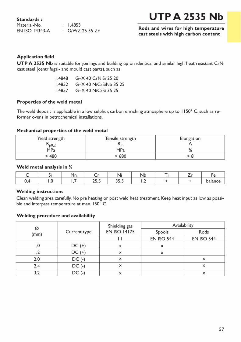
Rods and wires for high temperaturecast steels with high carbon content
UTP A 2535 Nb
Application fieldUTP A 2535 Nb is suitable for joinings and building up on identical and similar high heat resistant CrNicast steel (centrifugal- and mould cast parts), such as
1.4848 G–X 40 CrNiSi 25 201.4852 G–X 40 NiCrSiNb 35 251.4857 G–X 40 NiCrSi 35 25
Properties of the weld metalThe weld deposit is applicable in a low sulphur, carbon enriching atmosphere up to 1150° C, such as re-former ovens in petrochemical installations.
Welding instructionsClean welding area carefully. No pre heating or post weld heat treatment. Keep heat input as low as possi-ble and interpass temperature at max. 150° C.
Weld metal analysis in %C0,4
Si1,0
Mn1,7
Cr25,5
Ni35,5
Nb1,2
Ti+
Zr+
Febalance
Yield strengthRp0,2MPa> 480
Tensile strengthRmMPa> 680
ElongationA%> 8
Mechanical properties of the weld metal
Standards :Material-No. : 1.4853EN ISO 14343-A : G/WZ 25 35 Zr
Welding procedure and availability
Ø(mm) Current type
Shielding gasEN ISO 14175
AvailabilitySpools Rods
I 1 EN ISO 544 EN ISO 5441,0 DC (+) x x1,2 DC (+) x x2,0 DC (-) x x2,4 DC (-) x x3,2 DC (-) x x
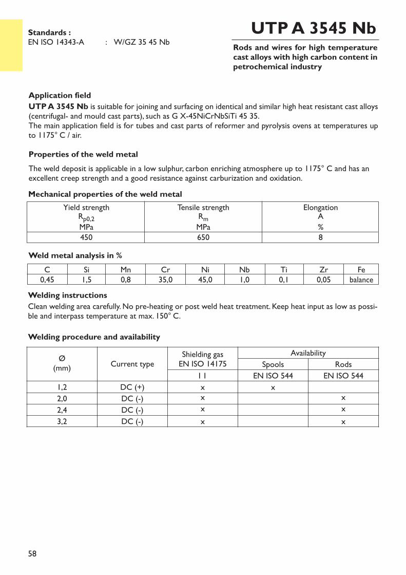
58
Rods and wires for high temperaturecast alloys with high carbon content inpetrochemical industry
UTP A 3545 Nb
Application fieldUTP A 3545 Nb is suitable for joining and surfacing on identical and similar high heat resistant cast alloys(centrifugal- and mould cast parts), such as G X-45NiCrNbSiTi 45 35.The main application field is for tubes and cast parts of reformer and pyrolysis ovens at temperatures upto 1175° C / air. Properties of the weld metalThe weld deposit is applicable in a low sulphur, carbon enriching atmosphere up to 1175° C and has anexcellent creep strength and a good resistance against carburization and oxidation.
Welding instructionsClean welding area carefully. No pre-heating or post weld heat treatment. Keep heat input as low as possi-ble and interpass temperature at max. 150° C.
Weld metal analysis in %C0,45
Si1,5
Mn0,8
Cr35,0
Ni45,0
Nb1,0
Ti0,1
Zr0,05
Febalance
Yield strengthRp0,2MPa450
Tensile strengthRmMPa650
ElongationA%8
Mechanical properties of the weld metal
Standards :EN ISO 14343-A : W/GZ 35 45 Nb
Welding procedure and availability
Ø(mm) Current type
Shielding gasEN ISO 14175
AvailabilitySpools Rods
I 1 EN ISO 544 EN ISO 5441,2 DC (+) x x2,0 DC (-) x x2,4 DC (-) x x3,2 DC (-) x x
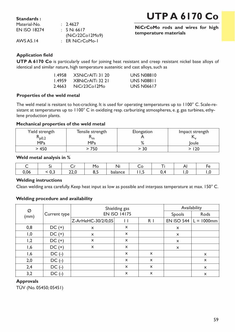
59
NiCrCoMo rods and wires for hightemperature materials
Application fieldUTP A 6170 Co is particularly used for joining heat resistant and creep resistant nickel base alloys ofidentical and similar nature, high temperature austenitic and cast alloys, such as
1.4958 X5NiCrAlTi 31 20 UNS N088101.4959 X8NiCrAlTi 32 21 UNS N088112.4663 NiCr23Co12Mo UNS N06617
Properties of the weld metalThe weld metal is resitant to hot-cracking. It is used for operating temperatures up to 1100° C. Scale-re-sistant at temperatures up to 1100° C in oxidizing resp. carburizing atmospheres, e. g. gas turbines, ethy-lene production plants.
Welding instructionsClean welding area carefully. Keep heat input as low as possible and interpass temperature at max. 150° C.
Weld metal analysis in %
UTP A 6170 Co
Yield strengthRp0,2MPa> 450
Tensile strengthRmMPa> 750
ElongationA%> 30
Impact strengthKvJoule> 120
Mechanical properties of the weld metal
Standards :Material-No. : 2.4627EN ISO 18274 : S Ni 6617
(NiCr22Co12Mo9)AWS A5.14 : ER NiCrCoMo-1
C0,06
Si< 0,3
Cr22,0
Mo8,5
Nibalance
Co11,5
Ti0,4
Al1,0
Fe1,0
ApprovalsTÜV (No. 05450; 05451)
Welding procedure and availability
Ø(mm) Current type
Shielding gasEN ISO 14175
AvailabilitySpools Rods
Z-ArHeHC-30/2/0,05 I 1 R 1 EN ISO 544 L = 1000mm0,8 DC (+) x x x1,0 DC (+) x x x1,2 DC (+) x x x1,6 DC (+) x x x1,6 DC (-) x x x2,0 DC (-) x x x2,4 DC (-) x x x3,2 DC (-) x x x
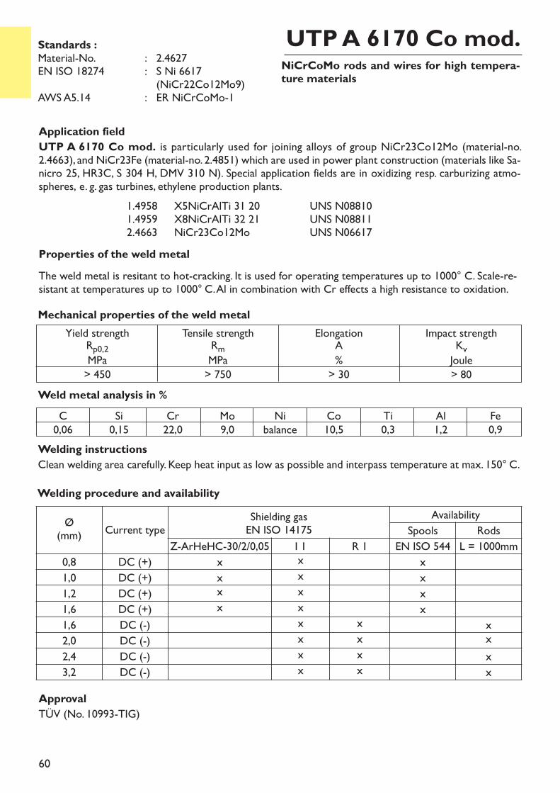
60
NiCrCoMo rods and wires for high tempera-ture materials
Application fieldUTP A 6170 Co mod. is particularly used for joining alloys of group NiCr23Co12Mo (material-no.2.4663), and NiCr23Fe (material-no. 2.4851) which are used in power plant construction (materials like Sa-nicro 25, HR3C, S 304 H, DMV 310 N). Special application fields are in oxidizing resp. carburizing atmo-spheres, e. g. gas turbines, ethylene production plants.
1.4958 X5NiCrAlTi 31 20 UNS N088101.4959 X8NiCrAlTi 32 21 UNS N088112.4663 NiCr23Co12Mo UNS N06617
Properties of the weld metalThe weld metal is resitant to hot-cracking. It is used for operating temperatures up to 1000° C. Scale-re-sistant at temperatures up to 1000° C. Al in combination with Cr effects a high resistance to oxidation.
Welding instructionsClean welding area carefully. Keep heat input as low as possible and interpass temperature at max. 150° C.
Weld metal analysis in %
UTP A 6170 Co mod.
Yield strengthRp0,2MPa> 450
Tensile strengthRmMPa> 750
ElongationA%> 30
Impact strengthKvJoule> 80
Mechanical properties of the weld metal
Standards :Material-No. : 2.4627EN ISO 18274 : S Ni 6617
(NiCr22Co12Mo9)AWS A5.14 : ER NiCrCoMo-1
C0,06
Si0,15
Cr22,0
Mo9,0
Nibalance
Co10,5
Ti0,3
Al1,2
Fe0,9
Welding procedure and availability
Ø(mm) Current type
Shielding gasEN ISO 14175
AvailabilitySpools Rods
Z-ArHeHC-30/2/0,05 I 1 R 1 EN ISO 544 L = 1000mm0,8 DC (+) x x x1,0 DC (+) x x x1,2 DC (+) x x x1,6 DC (+) x x x1,6 DC (-) x x x2,0 DC (-) x x x2,4 DC (-) x x x3,2 DC (-) x x x
ApprovalTÜV (No. 10993-TIG)
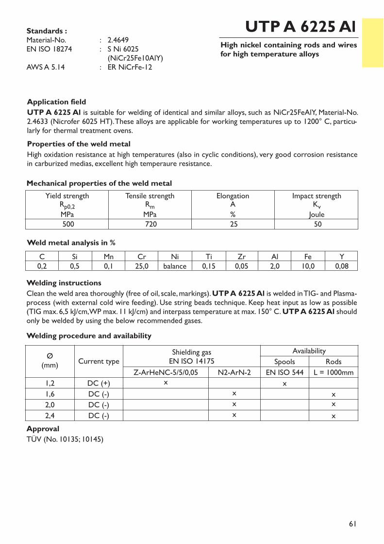
61
High nickel containing rods and wiresfor high temperature alloys
UTP A 6225 Al
Application fieldUTP A 6225 Al is suitable for welding of identical and similar alloys, such as NiCr25FeAlY, Material-No.2.4633 (Nicrofer 6025 HT). These alloys are applicable for working temperatures up to 1200° C, particu-larly for thermal treatment ovens.Properties of the weld metalHigh oxidation resistance at high temperatures (also in cyclic conditions), very good corrosion resistancein carburized medias, excellent high temperaure resistance.
Welding instructionsClean the weld area thoroughly (free of oil, scale, markings). UTP A 6225 Al is welded in TIG- and Plasma-process (with external cold wire feeding). Use string beads technique. Keep heat input as low as possible(TIG max. 6,5 kJ/cm, WP max. 11 kJ/cm) and interpass temperature at max. 150° C. UTP A 6225 Al shouldonly be welded by using the below recommended gases.
Weld metal analysis in %
Yield strengthRp0,2MPa500
Tensile strengthRmMPa720
ElongationA%25
Impact strengthKvJoule50
Mechanical properties of the weld metal
Standards :Material-No. : 2.4649EN ISO 18274 : S Ni 6025
(NiCr25Fe10AlY)AWS A 5.14 : ER NiCrFe-12
C0,2
Si0,5
Mn0,1
Cr25,0
Nibalance
Ti0,15
Zr0,05
Al2,0
Fe10,0
Y0,08
ApprovalTÜV (No. 10135; 10145)
Welding procedure and availability
Ø(mm) Current type
Shielding gasEN ISO 14175
AvailabilitySpools Rods
Z-ArHeNC-5/5/0,05 N2-ArN-2 EN ISO 544 L = 1000mm1,2 DC (+) x x1,6 DC (-) x x2,0 DC (-) x x2,4 DC (-) x x
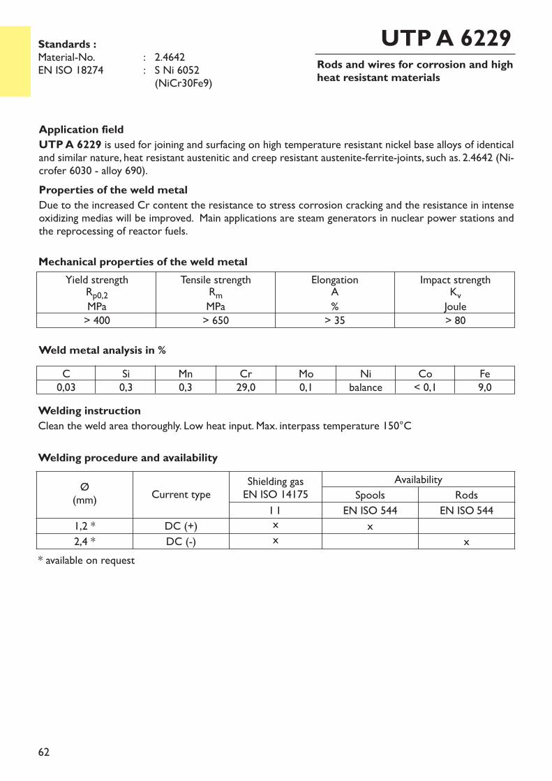
62
Rods and wires for corrosion and highheat resistant materials
Application fieldUTP A 6229 is used for joining and surfacing on high temperature resistant nickel base alloys of identicaland similar nature, heat resistant austenitic and creep resistant austenite-ferrite-joints, such as. 2.4642 (Ni-crofer 6030 - alloy 690). Properties of the weld metalDue to the increased Cr content the resistance to stress corrosion cracking and the resistance in intenseoxidizing medias will be improved. Main applications are steam generators in nuclear power stations andthe reprocessing of reactor fuels.
Weld metal analysis in %
UTP A 6229
Yield strengthRp0,2MPa> 400
Tensile strengthRmMPa> 650
ElongationA%> 35
Impact strengthKvJoule> 80
Mechanical properties of the weld metal
Standards :Material-No. : 2.4642EN ISO 18274 : S Ni 6052
(NiCr30Fe9)
C0,03
Si0,3
Mn0,3
Cr29,0
Mo0,1
Nibalance
Co< 0,1
Fe9,0
Welding procedure and availability
Ø(mm) Current type
Shielding gasEN ISO 14175
AvailabilitySpools Rods
I 1 EN ISO 544 EN ISO 5441,2 * DC (+) x x2,4 * DC (-) x x
* available on request
Welding instructionClean the weld area thoroughly. Low heat input. Max. interpass temperature 150°C
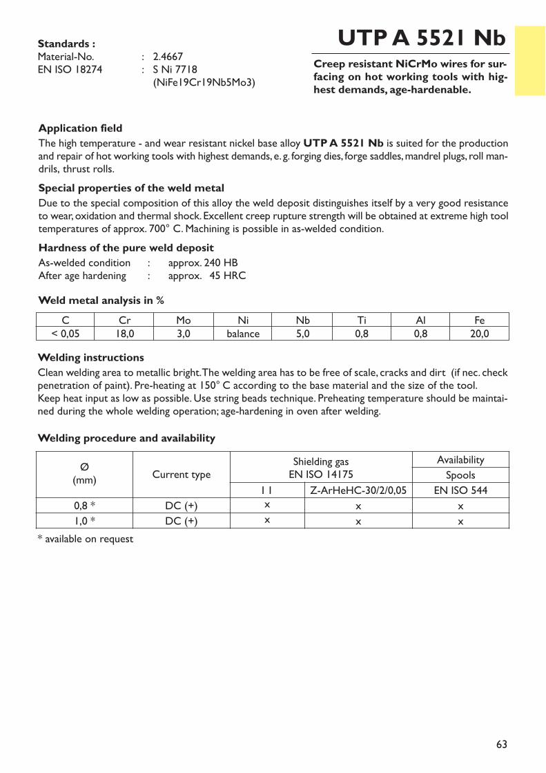
63
Creep resistant NiCrMo wires for sur-facing on hot working tools with hig-hest demands, age-hardenable.
UTP A 5521 Nb
Application fieldThe high temperature - and wear resistant nickel base alloy UTP A 5521 Nb is suited for the productionand repair of hot working tools with highest demands, e. g. forging dies, forge saddles, mandrel plugs, roll man-drils, thrust rolls.Special properties of the weld metalDue to the special composition of this alloy the weld deposit distinguishes itself by a very good resistanceto wear, oxidation and thermal shock. Excellent creep rupture strength will be obtained at extreme high tooltemperatures of approx. 700° C. Machining is possible in as-welded condition.Hardness of the pure weld depositAs-welded condition : approx. 240 HBAfter age hardening : approx. 45 HRC
Welding instructionsClean welding area to metallic bright. The welding area has to be free of scale, cracks and dirt (if nec. checkpenetration of paint). Pre-heating at 150° C according to the base material and the size of the tool.Keep heat input as low as possible. Use string beads technique. Preheating temperature should be maintai-ned during the whole welding operation; age-hardening in oven after welding.
Weld metal analysis in %
Standards :Material-No. : 2.4667EN ISO 18274 : S Ni 7718
(NiFe19Cr19Nb5Mo3)
C< 0,05
Cr18,0
Mo3,0
Nibalance
Nb5,0
Ti0,8
Al0,8
Fe20,0
Welding procedure and availability
Ø(mm) Current type
Shielding gasEN ISO 14175
AvailabilitySpools
I 1 Z-ArHeHC-30/2/0,05 EN ISO 5440,8 * DC (+) x x x1,0 * DC (+) x x x
* available on request
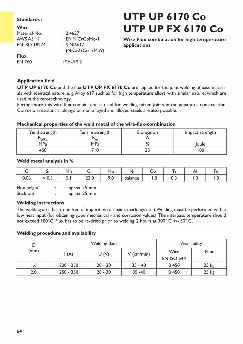
64
Wire Flux combination for high temperatureapplications
UTP UP 6170 CoUTP UP FX 6170 Co
Application fieldUTP UP 6170 Co and the flux UTP UP FX 6170 Co are applied for the joint welding of base materi-als with identical nature, e. g. Alloy 617 such as for high temperature alloys with similar nature, which areused in the terotechnology.Furthermore this wire-flux-combination is used for welding mixed joints in the apparatus construction.Corrosion resistant claddings on non-alloyed and alloyed steels are also possible.
Flux height : approx. 25 mmStick out : approx. 25 mmWelding instructionsThe welding area has to be free of impurities (oil, paint, markings etc.). Welding must be performed with alow heat input (for obtaining good mechanical - and corrosion values). The interpass temperature shouldnot exceed 100°C. Flux has to be re-dried prior to welding: 2 hours at 300° C +/- 50° C.
Weld metal analysis in %
Yield strengthRp0,2MPa450
Tensile strengthRmMPa710
ElongationA%35
Impact strengthJoule100
Mechanical properties of the weld metal of the wire-flux-combination
Standards :Wire Material-No. : 2.4627AWS A5.14 : ER NiCrCoMo-1EN ISO 18274 : S Ni6617
(NiCr22Co12Mo9)FluxEN 760 : SA-AB 2
C Si Mn Cr Mo Ni Co Ti Al Fe0,06 < 0,3 0,1 22,0 9,0 balance 11,0 0,3 1,0 1,0
Welding procedure and availabilityØ(mm)
Welding data AvailabilityI (A) U (V) V (cm/min) Wire Flux
EN ISO 5441,6 200 - 250 28 - 30 35 - 40 B 450 25 kg2,0 250 - 350 28 - 30 35 -40 B 450 25 kg
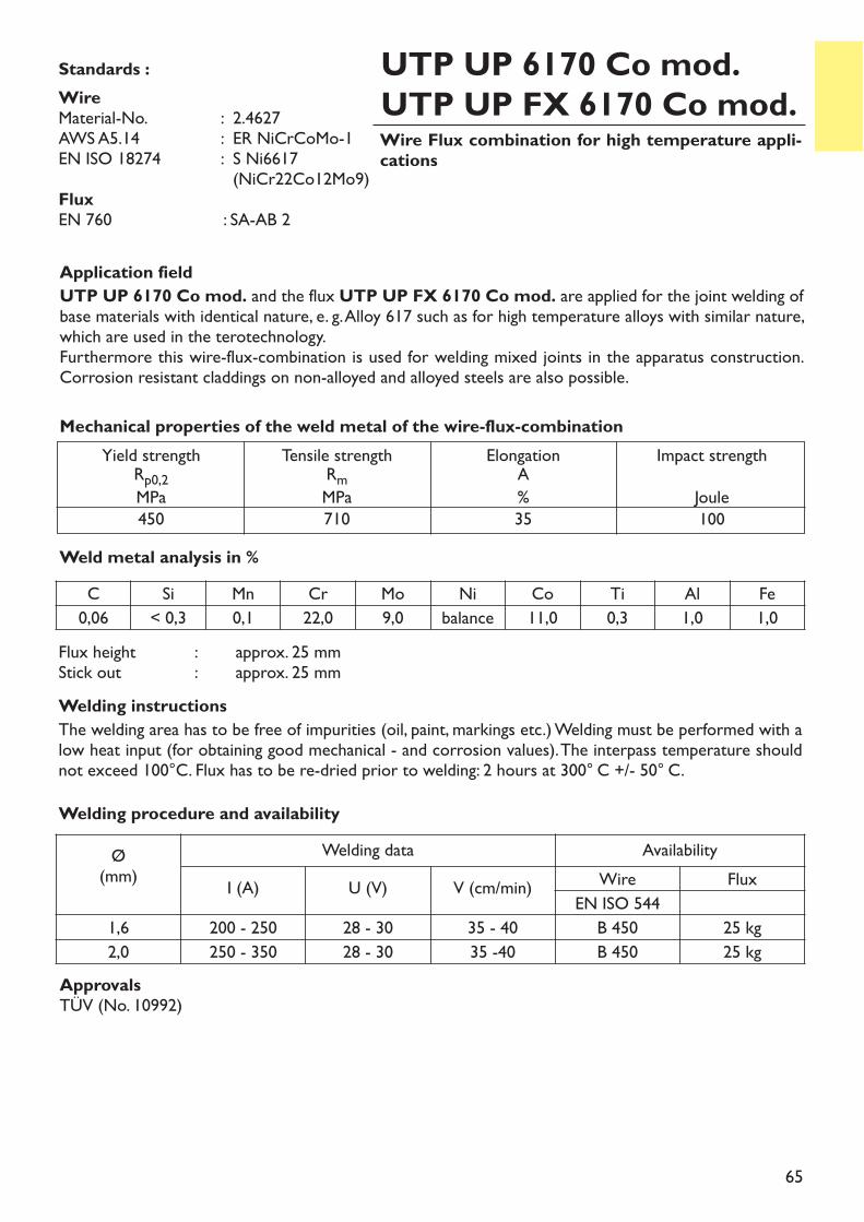
65
Wire Flux combination for high temperature appli-cations
UTP UP 6170 Co mod.UTP UP FX 6170 Co mod.
Application fieldUTP UP 6170 Co mod. and the flux UTP UP FX 6170 Co mod. are applied for the joint welding ofbase materials with identical nature, e. g. Alloy 617 such as for high temperature alloys with similar nature,which are used in the terotechnology.Furthermore this wire-flux-combination is used for welding mixed joints in the apparatus construction.Corrosion resistant claddings on non-alloyed and alloyed steels are also possible.
Flux height : approx. 25 mmStick out : approx. 25 mmWelding instructionsThe welding area has to be free of impurities (oil, paint, markings etc.) Welding must be performed with alow heat input (for obtaining good mechanical - and corrosion values). The interpass temperature shouldnot exceed 100°C. Flux has to be re-dried prior to welding: 2 hours at 300° C +/- 50° C.
Weld metal analysis in %
Yield strengthRp0,2MPa450
Tensile strengthRmMPa710
ElongationA%35
Impact strengthJoule100
Mechanical properties of the weld metal of the wire-flux-combination
Standards :Wire Material-No. : 2.4627AWS A5.14 : ER NiCrCoMo-1EN ISO 18274 : S Ni6617
(NiCr22Co12Mo9)FluxEN 760 : SA-AB 2
C Si Mn Cr Mo Ni Co Ti Al Fe0,06 < 0,3 0,1 22,0 9,0 balance 11,0 0,3 1,0 1,0
Welding procedure and availabilityØ(mm)
Welding data AvailabilityI (A) U (V) V (cm/min) Wire Flux
EN ISO 5441,6 200 - 250 28 - 30 35 - 40 B 450 25 kg2,0 250 - 350 28 - 30 35 -40 B 450 25 kg
ApprovalsTÜV (No. 10992)
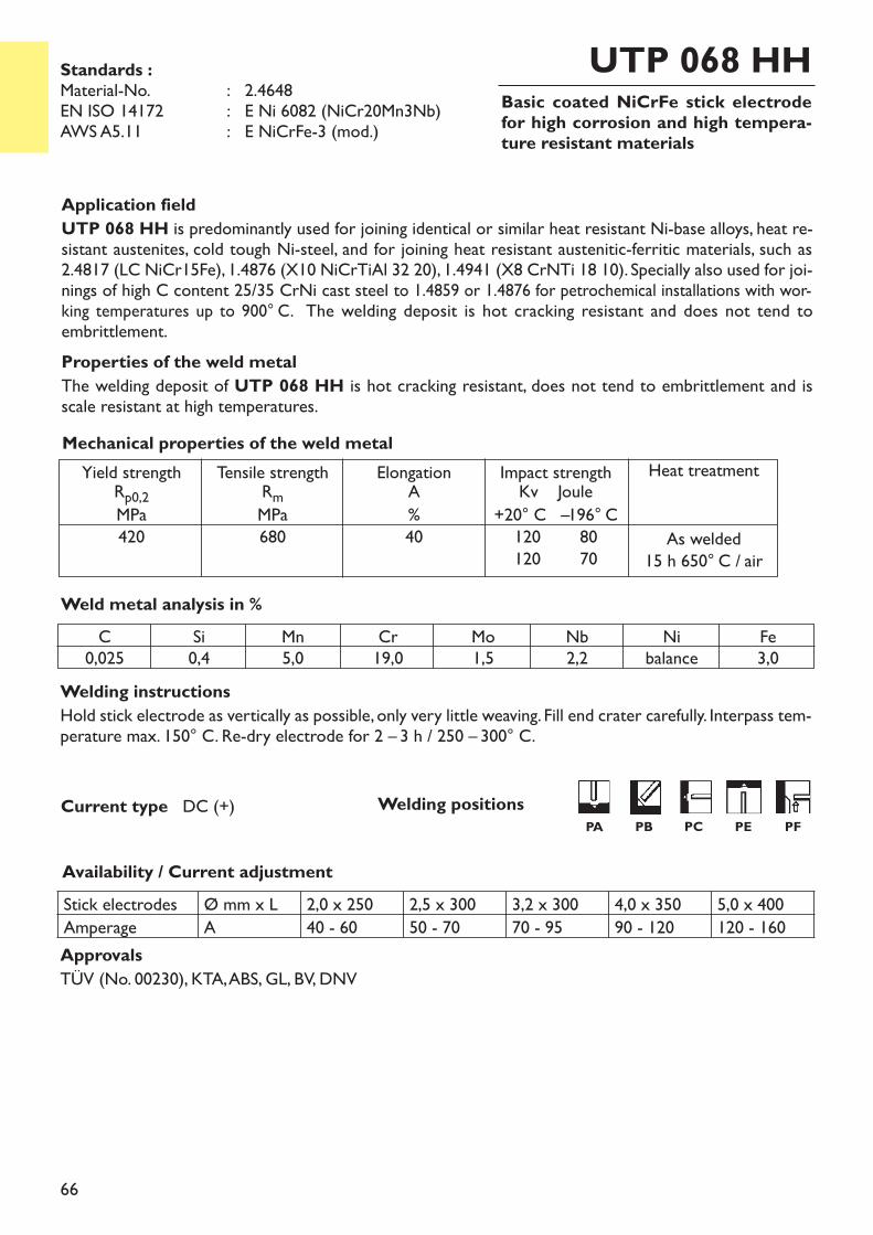
66
Basic coated NiCrFe stick electrodefor high corrosion and high tempera-ture resistant materials
UTP 068 HH
Welding instructionsHold stick electrode as vertically as possible, only very little weaving. Fill end crater carefully. Interpass tem-perature max. 150° C. Re-dry electrode for 2 – 3 h / 250 – 300° C.
Availability / Current adjustment
Current type DC (+)
Application fieldUTP 068 HH is predominantly used for joining identical or similar heat resistant Ni-base alloys, heat re-sistant austenites, cold tough Ni-steel, and for joining heat resistant austenitic-ferritic materials, such as2.4817 (LC NiCr15Fe), 1.4876 (X10 NiCrTiAl 32 20), 1.4941 (X8 CrNTi 18 10). Specially also used for joi-nings of high C content 25/35 CrNi cast steel to 1.4859 or 1.4876 for petrochemical installations with wor-king temperatures up to 900° C. The welding deposit is hot cracking resistant and does not tend toembrittlement.Properties of the weld metalThe welding deposit of UTP 068 HH is hot cracking resistant, does not tend to embrittlement and isscale resistant at high temperatures.
Weld metal analysis in %
Yield strengthRp0,2MPa420
Tensile strengthRmMPa680
ElongationA%40
Impact strengthKv Joule+20° C –196° C120 80120 70
Heat treatment
As welded 15 h 650° C / air
Mechanical properties of the weld metal
Standards :Material-No. : 2.4648EN ISO 14172 : E Ni 6082 (NiCr20Mn3Nb)AWS A5.11 : E NiCrFe-3 (mod.)
C0,025
Si0,4
Mn5,0
Cr19,0
Mo1,5
Nb2,2
Nibalance
Fe3,0
Stick electrodes Ø mm x L 2,0 x 250 2,5 x 300 3,2 x 300 4,0 x 350 5,0 x 400Amperage A 40 - 60 50 - 70 70 - 95 90 - 120 120 - 160ApprovalsTÜV (No. 00230), KTA, ABS, GL, BV, DNV
Welding positionsPA PB PC PE PF
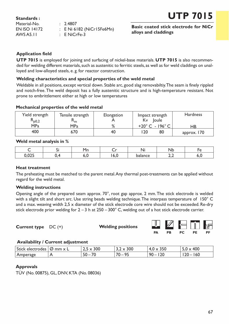
67
Basic coated stick electrode for NiCralloys and claddings
UTP 7015
Heat treatmentThe preheating must be matched to the parent metal. Any thermal post-treatments can be applied withoutregard for the weld metal.Welding instructionsOpening angle of the prepared seam approx. 70°, root gap approx. 2 mm. The stick electrode is weldedwith a slight tilt and short arc. Use string beads welding technique. The interpass temperature of 150° Cand a max. weaving width 2,5 x diameter of the stick electrode core wire should not be exceeded. Re-drystick electrode prior welding for 2 – 3 h at 250 – 300° C, welding out of a hot stick electrode carrier.
Availability / Current adjustment
Current type DC (+)
Application fieldUTP 7015 is employed for joining and surfacing of nickel-base materials. UTP 7015 is also recommen-ded for welding different materials, such as austenitic to ferritic steels, as well as for weld claddings on unal-loyed and low-alloyed steels, e. g. for reactor construction.Welding characteristics and special properties of the weld metalWeldable in all positions, except vertical down. Stable arc, good slag removabiltiy. The seam is finely rippledand notch-free.The weld deposit has a fully austenitic structure and is high-temperature resistant. Notprone to embrittlement either at high or low temperatures
Weld metal analysis in %
Stick electrodesAmperage
Ø mm x LA
2,5 x 30050 – 70
3,2 x 30070 – 95
4,0 x 35090 – 120
5,0 x 400120 – 160
Yield strengthRp0,2MPa400
Tensile strengthRmMPa670
ElongationA%40
Impact strengthKv Joule+20° C - 196° C120 80
HardnessHB
approx. 170
Mechanical properties of the weld metal
Standards :Material-No. : 2.4807EN ISO 14172 : E Ni 6182 (NiCr15Fe6Mn)AWS A5.11 : E NiCrFe-3
C0,025
Si0,4
Mn6,0
Cr16,0
Nibalance
Nb2,2
Fe6,0
Approvals TÜV (No. 00875), GL, DNV, KTA (No. 08036)
Welding positionsPA PB PC PE PF
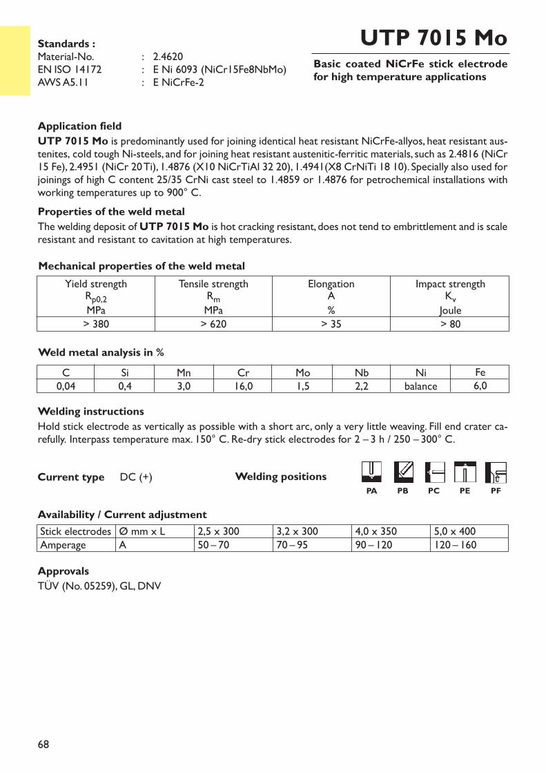
68
Basic coated NiCrFe stick electrodefor high temperature applications
UTP 7015 Mo
Welding instructionsHold stick electrode as vertically as possible with a short arc, only a very little weaving. Fill end crater ca-refully. Interpass temperature max. 150° C. Re-dry stick electrodes for 2 – 3 h / 250 – 300° C.
Availability / Current adjustment
Application fieldUTP 7015 Mo is predominantly used for joining identical heat resistant NiCrFe-allyos, heat resistant aus-tenites, cold tough Ni-steels, and for joining heat resistant austenitic-ferritic materials, such as 2.4816 (NiCr15 Fe), 2.4951 (NiCr 20 Ti), 1.4876 (X10 NiCrTiAl 32 20), 1.4941(X8 CrNiTi 18 10). Specially also used forjoinings of high C content 25/35 CrNi cast steel to 1.4859 or 1.4876 for petrochemical installations withworking temperatures up to 900° C. Properties of the weld metalThe welding deposit of UTP 7015 Mo is hot cracking resistant, does not tend to embrittlement and is scaleresistant and resistant to cavitation at high temperatures.
Weld metal analysis in %
Stick electrodesAmperage
Ø mm x LA
2,5 x 30050 – 70
3,2 x 30070 – 95
4,0 x 35090 – 120
5,0 x 400120 – 160
Yield strengthRp0,2MPa> 380
Tensile strengthRmMPa> 620
ElongationA%> 35
Impact strengthKvJoule> 80
Mechanical properties of the weld metal
Current type DC (+)
Standards :Material-No. : 2.4620EN ISO 14172 : E Ni 6093 (NiCr15Fe8NbMo)AWS A5.11 : E NiCrFe-2
C0,04
Si0,4
Mn3,0
Cr16,0
Mo1,5
Nb2,2
Nibalance
Fe6,0
ApprovalsTÜV (No. 05259), GL, DNV
Welding positionsPA PB PC PE PF
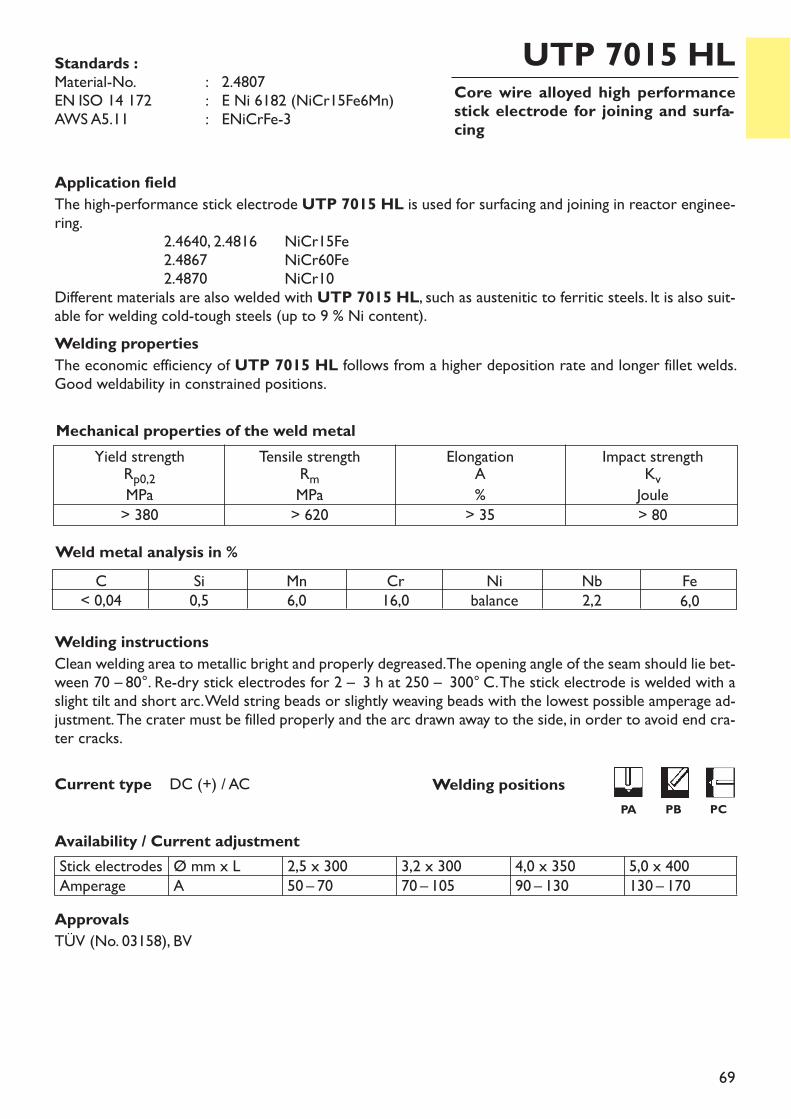
69
Core wire alloyed high performancestick electrode for joining and surfa-cing
UTP 7015 HL
Welding instructionsClean welding area to metallic bright and properly degreased. The opening angle of the seam should lie bet-ween 70 – 80°. Re-dry stick electrodes for 2 – 3 h at 250 – 300° C. The stick electrode is welded with aslight tilt and short arc. Weld string beads or slightly weaving beads with the lowest possible amperage ad-justment. The crater must be filled properly and the arc drawn away to the side, in order to avoid end cra-ter cracks.
Availability / Current adjustment
Current type DC (+) / AC
Application fieldThe high-performance stick electrode UTP 7015 HL is used for surfacing and joining in reactor enginee-ring.
2.4640, 2.4816 NiCr15Fe2.4867 NiCr60Fe2.4870 NiCr10
Different materials are also welded with UTP 7015 HL, such as austenitic to ferritic steels. lt is also suit-able for welding cold-tough steels (up to 9 % Ni content).Welding propertiesThe economic efficiency of UTP 7015 HL follows from a higher deposition rate and longer fillet welds.Good weldability in constrained positions.
Weld metal analysis in %
Stick electrodesAmperage
Ø mm x LA
2,5 x 30050 – 70
3,2 x 30070 – 105
4,0 x 35090 – 130
5,0 x 400130 – 170
Yield strengthRp0,2MPa> 380
Tensile strengthRmMPa> 620
ElongationA%> 35
Impact strengthKvJoule> 80
Mechanical properties of the weld metal
Standards :Material-No. : 2.4807EN ISO 14 172 : E Ni 6182 (NiCr15Fe6Mn)AWS A5.11 : ENiCrFe-3
C< 0,04
Si0,5
Mn6,0
Cr16,0
Nibalance
Nb2,2
Fe6,0
ApprovalsTÜV (No. 03158), BV
Welding positionsPA PB PC
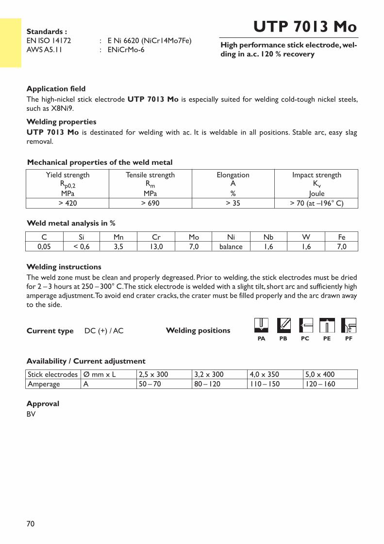
70
High performance stick electrode, wel-ding in a.c. 120 % recovery
UTP 7013 Mo
Welding instructionsThe weld zone must be clean and properly degreased. Prior to welding, the stick electrodes must be driedfor 2 –3 hours at 250 –300° C. The stick electrode is welded with a slight tilt, short arc and sufficiently highamperage adjustment. To avoid end crater cracks, the crater must be filled properly and the arc drawn awayto the side.
Availability / Current adjustment
Current type DC (+) / AC
Application fieldThe high-nickel stick electrode UTP 7013 Mo is especially suited for welding cold-tough nickel steels,such as X8Ni9.Welding propertiesUTP 7013 Mo is destinated for welding with ac. It is weldable in all positions. Stable arc, easy slag removal.
Weld metal analysis in %
Yield strengthRp0,2MPa> 420
Tensile strengthRmMPa> 690
ElongationA%> 35
Impact strengthKvJoule> 70 (at –196° C)
Mechanical properties of the weld metal
Standards :EN ISO 14172 : E Ni 6620 (NiCr14Mo7Fe)AWS A5.11 : ENiCrMo-6
C0,05
Si< 0,6
Mn3,5
Cr13,0
Mo7,0
Nibalance
Nb1,6
W1,6
Fe7,0
Welding positionsPA PB PC PE PF
Stick electrodesAmperage
Ø mm x LA
2,5 x 30050 – 70
3,2 x 30080 – 120
4,0 x 350110 – 150
5,0 x 400120 – 160
ApprovalBV
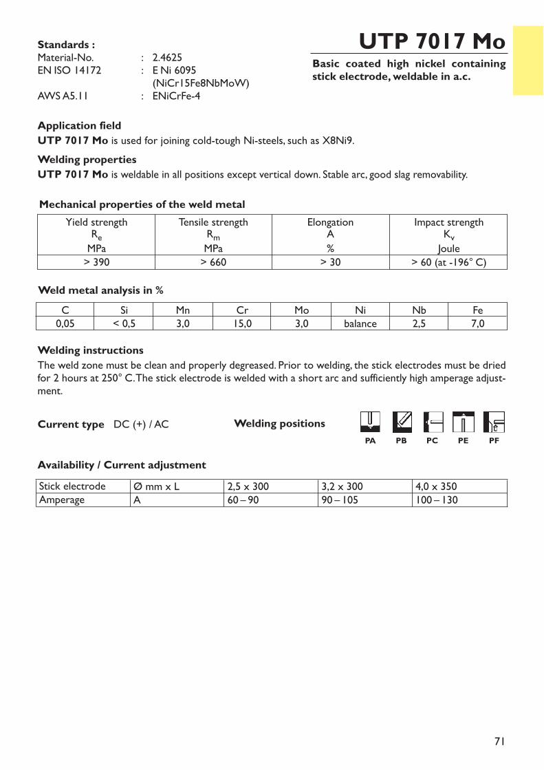
71
Basic coated high nickel containingstick electrode, weldable in a.c.
UTP 7017 Mo
Welding instructionsThe weld zone must be clean and properly degreased. Prior to welding, the stick electrodes must be driedfor 2 hours at 250° C. The stick electrode is welded with a short arc and sufficiently high amperage adjust-ment.
Availability / Current adjustment
Current type DC (+) / AC
Application fieldUTP 7017 Mo is used for joining cold-tough Ni-steels, such as X8Ni9.Welding propertiesUTP 7017 Mo is weldable in all positions except vertical down. Stable arc, good slag removability.
Weld metal analysis in %
Yield strengthReMPa> 390
Tensile strengthRmMPa> 660
ElongationA%> 30
Impact strengthKvJoule> 60 (at -196° C)
Mechanical properties of the weld metal
Standards :Material-No. : 2.4625EN ISO 14172 : E Ni 6095
(NiCr15Fe8NbMoW)AWS A5.11 : ENiCrFe-4
C0,05
Si< 0,5
Mn3,0
Cr15,0
Mo3,0
Nibalance
Nb2,5
Fe7,0
Stick electrodeAmperage
Ø mm x LA
2,5 x 30060 – 90
3,2 x 30090 – 105
4,0 x 350100 – 130
Welding positionsPA PB PC PE PF
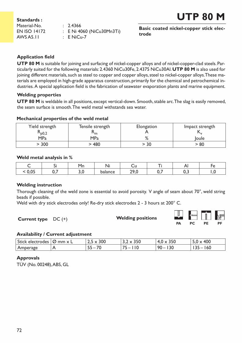
72
Basic coated nickel-copper stick elec-trode
UTP 80 M
Welding instructionThorough cleaning of the weld zone is essential to avoid porosity. V angle of seam about 70°, weld stringbeads if possible.Weld with dry stick electrodes only! Re-dry stick electrodes 2 - 3 hours at 200° C.
Availability / Current adjustment
Current type DC (+)
Application fieldUTP 80 M is suitable for joining and surfacing of nickel-copper alloys and of nickel-copper-clad steels. Par-ticularly suited for the following materials: 2.4360 NiCu30Fe, 2.4375 NiCu30Al. UTP 80 M is also used forjoining different materials, such as steel to copper and copper alloys, steel to nickel-copper alloys. These ma-terials are employed in high-grade apparatus construction, primarily for the chemical and petrochemical in-dustries. A special application field is the fabrication of seawater evaporation plants and marine equipment.Welding propertiesUTP 80 M is weldable in all positions, except vertical-down. Smooth, stable arc. The slag is easily removed,the seam surface is smooth. The weld metal withstands sea water.
Weld metal analysis in %
Stick electrodesAmperage
Ø mm x LA
2,5 x 30055 – 70
3,2 x 35075 – 110
4,0 x 35090 – 130
5,0 x 400135 – 160
Yield strengthRp0,2MPa> 300
Tensile strengthRmMPa> 480
ElongationA%> 30
Impact strengthKvJoule> 80
Mechanical properties of the weld metal
Standards :Material-No. : 2.4366EN ISO 14172 : E Ni 4060 (NiCu30Mn3Ti)AWS A5.11 : E NiCu-7
C< 0,05
Si0,7
Mn3,0
Nibalance
Cu29,0
Ti0,7
Al0,3
Fe1,0
ApprovalsTÜV (No. 00248), ABS, GL
Welding positionsPA PC PE PF
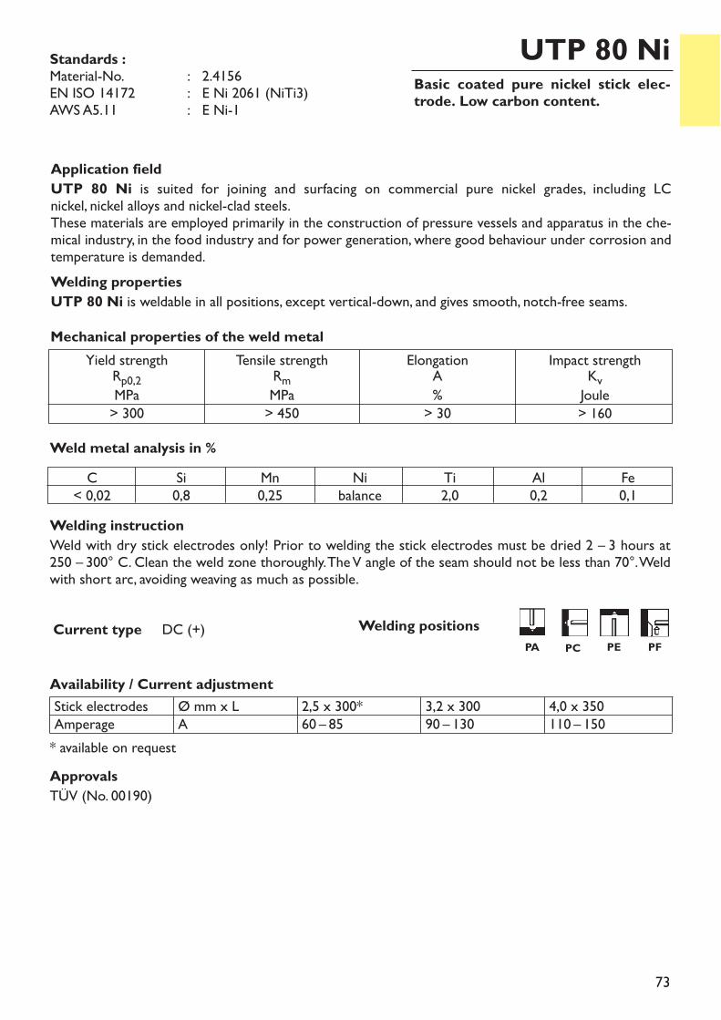
73
Basic coated pure nickel stick elec-trode. Low carbon content.
UTP 80 Ni
Welding instructionWeld with dry stick electrodes only! Prior to welding the stick electrodes must be dried 2 – 3 hours at 250 – 300° C. Clean the weld zone thoroughly. The V angle of the seam should not be less than 70°. Weldwith short arc, avoiding weaving as much as possible.
Availability / Current adjustment
Current type DC (+)
Application fieldUTP 80 Ni is suited for joining and surfacing on commercial pure nickel grades, including LC nickel, nickel alloys and nickel-clad steels.These materials are employed primarily in the construction of pressure vessels and apparatus in the che-mical industry, in the food industry and for power generation, where good behaviour under corrosion andtemperature is demanded.Welding propertiesUTP 80 Ni is weldable in all positions, except vertical-down, and gives smooth, notch-free seams.
Weld metal analysis in %
Stick electrodesAmperage
Ø mm x LA
2,5 x 300*60 – 85
3,2 x 30090 – 130
4,0 x 350110 – 150
* available on request
Yield strengthRp0,2MPa> 300
Tensile strengthRmMPa> 450
ElongationA%> 30
Impact strengthKvJoule> 160
Mechanical properties of the weld metal
Standards :Material-No. : 2.4156EN ISO 14172 : E Ni 2061 (NiTi3)AWS A5.11 : E Ni-1
C< 0,02
Si0,8
Mn0,25
Nibalance
Ti2,0
Al0,2
Fe0,1
ApprovalsTÜV (No. 00190)
Welding positionsPA PC PE PF
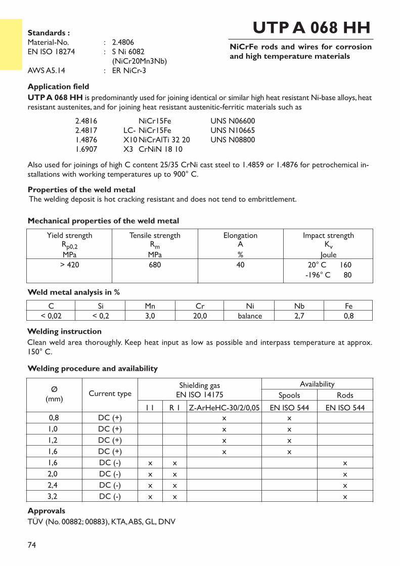
74
NiCrFe rods and wires for corrosionand high temperature materials
UTP A 068 HH
Application fieldUTP A 068 HH is predominantly used for joining identical or similar high heat resistant Ni-base alloys, heatresistant austenites, and for joining heat resistant austenitic-ferritic materials such as
2.4816 NiCr15Fe UNS N066002.4817 LC- NiCr15Fe UNS N106651.4876 X10NiCrAlTi 32 20 UNS N088001.6907 X3 CrNiN 18 10
Also used for joinings of high C content 25/35 CrNi cast steel to 1.4859 or 1.4876 for petrochemical in-stallations with working temperatures up to 900° C.Properties of the weld metalThe welding deposit is hot cracking resistant and does not tend to embrittlement.
Welding instructionClean weld area thoroughly. Keep heat input as low as possible and interpass temperature at approx. 150° C.
Weld metal analysis in %
Yield strengthRp0,2MPa> 420
Tensile strengthRmMPa680
ElongationA%40
Impact strengthKvJoule20° C 160-196° C 80
Mechanical properties of the weld metal
Standards :Material-No. : 2.4806EN ISO 18274 : S Ni 6082
(NiCr20Mn3Nb)AWS A5.14 : ER NiCr-3
C< 0,02
Si< 0,2
Mn3,0
Cr20,0
Nibalance
Nb2,7
Fe0,8
ApprovalsTÜV (No. 00882; 00883), KTA, ABS, GL, DNV
Welding procedure and availability
Ø(mm) Current type Shielding gas
EN ISO 14175Availability
Spools RodsI 1 R 1 Z-ArHeHC-30/2/0,05 EN ISO 544 EN ISO 544
0,8 DC (+) x x1,0 DC (+) x x1,2 DC (+) x x1,6 DC (+) x x1,6 DC (-) x x x2,0 DC (-) x x x2,4 DC (-) x x x3,2 DC (-) x x x
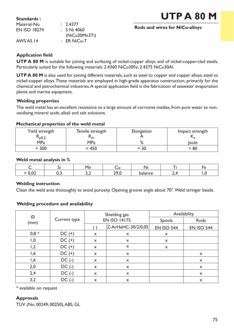
75
Rods and wires for NiCu-alloysUTP A 80 M
Application fieldUTP A 80 M is suitable for joining and surfacing of nickel-copper alloys and of nickel-copper-clad steels.Particularly suited for the following materials: 2.4360 NiCu30Fe, 2.4375 NiCu30Al.UTP A 80 M is also used for joining different materials, such as steel to copper and copper alloys, steel tonickel-copper alloys. These materials are employed in high-grade apparatus construction, primarily for thechemical and petrochemical industries. A special application field is the fabrication of seawater evaporationplants and marine equipment.Welding propertiesThe weld metal has an excellent resistance to a large amount of corrosive medias, from pure water to non-oxidising mineral acids, alkali and salt solutions.
Weld metal analysis in %
Yield strengthRp0,2MPa> 300
Tensile strengthRmMPa> 450
ElongationA%> 30
Impact strengthKvJoule> 80
Mechanical properties of the weld metal
Welding procedure and availability
Ø(mm) Current type Shielding gas
EN ISO 14175Availability
Spools RodsI 1 Z-ArHeHC-30/2/0,05 EN ISO 544 EN ISO 544
0,8 * DC (+) x x x1,0 DC (+) x x x1,2 DC (+) x x x1,6 DC (+) x x x1,6 DC (-) x x x2,0 DC (-) x x x2,4 DC (-) x x x3,2 DC (-) x x x
Welding instructionClean the weld area thotoughly to avoid porosity. Opening groove angle about 70°. Weld stringer beads.
C< 0,02
Si0,3
Mn3,2
Cu29,0
Nibalance
Ti2,4
Fe1,0
Standards :Material-No. : 2.4377EN ISO 18274 : S Ni 4060
(NiCu30Mn3Ti)AWS A5.14 : ER NiCu-7
ApprovalsTÜV (No. 00249; 00250), ABS, GL
* available on request
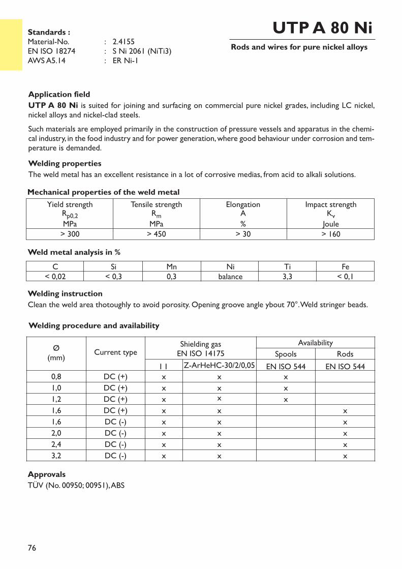
76
Rods and wires for pure nickel alloysUTP A 80 Ni
Application fieldUTP A 80 Ni is suited for joining and surfacing on commercial pure nickel grades, including LC nickel,nickel alloys and nickel-clad steels.Such materials are employed primarily in the construction of pressure vessels and apparatus in the chemi-cal industry, in the food industry and for power generation, where good behaviour under corrosion and tem-perature is demanded.Welding propertiesThe weld metal has an excellent resistance in a lot of corrosive medias, from acid to alkali solutions.
Weld metal analysis in %C
< 0,02Si< 0,3
Mn0,3
Nibalance
Ti3,3
Fe< 0,1
Yield strengthRp0,2MPa> 300
Tensile strengthRmMPa> 450
ElongationA%> 30
Impact strengthKvJoule> 160
Mechanical properties of the weld metal
ApprovalsTÜV (No. 00950; 00951), ABS
Welding procedure and availability
Ø(mm) Current type Shielding gas
EN ISO 14175Availability
Spools RodsI 1 Z-ArHeHC-30/2/0,05 EN ISO 544 EN ISO 544
0,8 DC (+) x x x1,0 DC (+) x x x1,2 DC (+) x x x1,6 DC (+) x x x1,6 DC (-) x x x2,0 DC (-) x x x2,4 DC (-) x x x3,2 DC (-) x x x
Standards :Material-No. : 2.4155EN ISO 18274 : S Ni 2061 (NiTi3)AWS A5.14 : ER Ni-1
Welding instructionClean the weld area thotoughly to avoid porosity. Opening groove angle ybout 70°. Weld stringer beads.
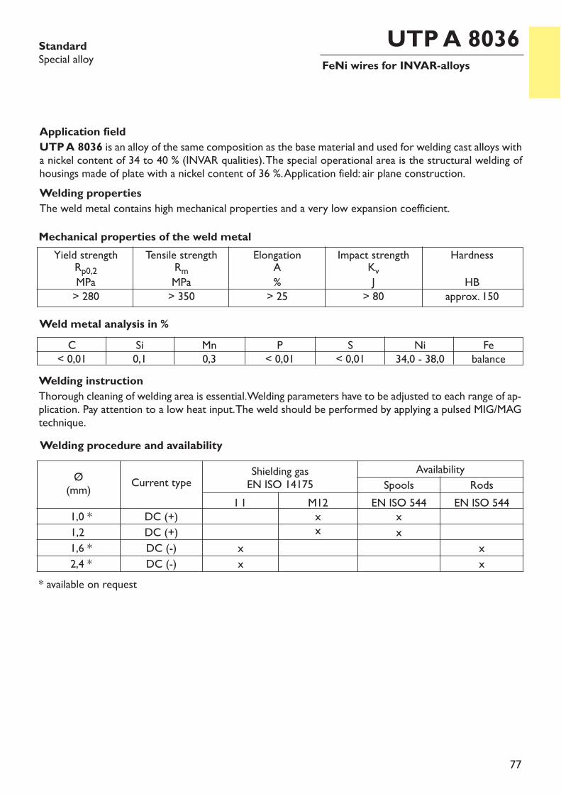
77
FeNi wires for INVAR-alloysUTP A 8036Standard
Special alloy
Application fieldUTP A 8036 is an alloy of the same composition as the base material and used for welding cast alloys witha nickel content of 34 to 40 % (INVAR qualities). The special operational area is the structural welding ofhousings made of plate with a nickel content of 36 %. Application field: air plane construction.Welding propertiesThe weld metal contains high mechanical properties and a very low expansion coefficient.
Welding instructionThorough cleaning of welding area is essential. Welding parameters have to be adjusted to each range of ap-plication. Pay attention to a low heat input. The weld should be performed by applying a pulsed MIG/MAGtechnique.
Weld metal analysis in %
Yield strengthRp0,2MPa> 280
Tensile strengthRmMPa> 350
ElongationA%> 25
Impact strengthKvJ> 80
HardnessHB
approx. 150
Mechanical properties of the weld metal
C< 0,01
Si0,1
Mn0,3
P< 0,01
S< 0,01
Ni34,0 - 38,0
Febalance
Welding procedure and availability
Ø(mm) Current type Shielding gas
EN ISO 14175Availability
Spools RodsI 1 M12 EN ISO 544 EN ISO 544
1,0 * DC (+) x x1,2 DC (+) x x1,6 * DC (-) x x2,4 * DC (-) x x
* available on request

78
Ferro-Nickel rods and wires for INVARalloys
UTP A 8036 SStandardsSpecial alloy
Application fieldUTP A 8036 S is an alloy of the same composition as the base material and used for welding cast alloyswith a nickel content of 34 - 40 % (INVAR qualities). The special operational area is the structural weldingof housings made of plate and cast pieces with a nickel content of 36 %. Application field: air plane con-struction.Welding propertiesThe weld metal contains high mechanical properties and a very low expansion coefficient.
Welding instructionThorough cleaning of welding area is essential. Welding parameters have to be adjusted to each range of ap-plication. Pay attention to a low heat input. The weld should be performed by applying a pulsed technique.
Weld metal analysis in %
Yield strengthRp0,2MPa> 280
Tensile strengthRmMPa> 350
ElongationA%> 25
Impact strengthKvJ> 80
HardnessHB
appr. 150
Mechanical properties of the weld metal
C0,015 - 0,025
Si0,1
Mn0,3
P< 0,01
S< 0,01
Ni34,0 - 38,0
Febalance
Welding procedure and availability
Ø(mm) Current type Shielding gas
EN ISO 14175Availability
Spools RodsI 1 M12 EN ISO 544 EN ISO 544
1,2 DC (+) x x2,0 * DC (-) x x2,4 * DC (-) x x
* available on request
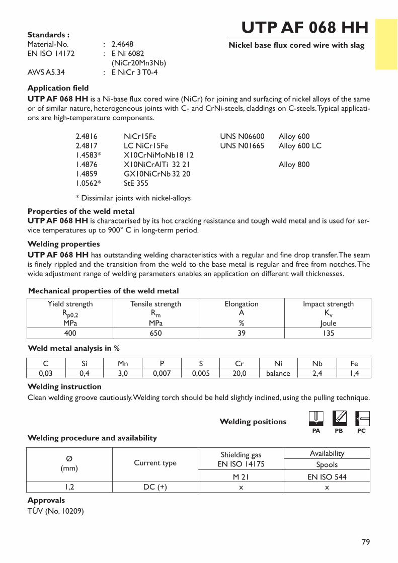
79
Nickel base flux cored wire with slagUTP AF 068 HH
Application fieldUTP AF 068 HH is a Ni-base flux cored wire (NiCr) for joining and surfacing of nickel alloys of the sameor of similar nature, heterogeneous joints with C- and CrNi-steels, claddings on C-steels. Typical applicati-ons are high-temperature components.
2.4816 NiCr15Fe UNS N06600 Alloy 6002.4817 LC NiCr15Fe UNS N01665 Alloy 600 LC1.4583* X10CrNiMoNb18 121.4876 X10NiCrAlTi 32 21 Alloy 8001.4859 GX10NiCrNb 32 201.0562* StE 355* Dissimilar joints with nickel-alloys
Properties of the weld metalUTP AF 068 HH is characterised by its hot cracking resistance and tough weld metal and is used for ser-vice temperatures up to 900° C in long-term period.Welding propertiesUTP AF 068 HH has outstanding welding characteristics with a regular and fine drop transfer. The seamis finely rippled and the transition from the weld to the base metal is regular and free from notches. Thewide adjustment range of welding parameters enables an application on different wall thicknesses.
Welding instructionClean welding groove cautiously. Welding torch should be held slightly inclined, using the pulling technique.
Weld metal analysis in %
Yield strengthRp0,2MPa400
Tensile strengthRmMPa650
ElongationA%39
Impact strengthKvJoule135
Mechanical properties of the weld metal
Standards :Material-No. : 2.4648EN ISO 14172 : E Ni 6082
(NiCr20Mn3Nb)AWS A5.34 : E NiCr 3 T0-4
C0,03
Si0,4
Mn3,0
P0,007
S0,005
Cr20,0
Nibalance
Nb2,4
Fe1,4
ApprovalsTÜV (No. 10209)
Welding procedure and availability
Ø(mm) Current type Shielding gas
EN ISO 14175AvailabilitySpools
M 21 EN ISO 5441,2 DC (+) x x
Welding positionsPA PB PC
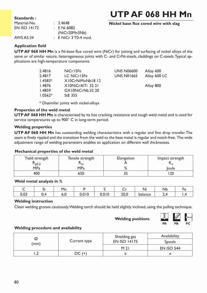
80
Nickel base flux cored wire with slagUTP AF 068 HH Mn
Application fieldUTP AF 068 HH Mn is a Ni-base flux cored wire (NiCr) for joining and surfacing of nickel alloys of thesame or of similar nature, heterogeneous joints with C- and CrNi-steels, claddings on C-steels. Typical ap-plications are high-temperature components.
2.4816 NiCr15Fe UNS N06600 Alloy 6002.4817 LC NiCr15Fe UNS N01665 Alloy 600 LC1.4583* X10CrNiMoNb18 121.4876 X10NiCrAlTi 32 21 Alloy 8001.4859 GX10NiCrNb 32 201.0562* StE 355* Dissimilar joints with nickel-alloys
Properties of the weld metalUTP AF 068 HH Mn is characterised by its hot cracking resistance and tough weld metal and is used forservice temperatures up to 900° C in long-term period.Welding propertiesUTP AF 068 HH Mn has outstanding welding characteristics with a regular and fine drop transfer. Theseam is finely rippled and the transition from the weld to the base metal is regular and notch-free. The wideadjustment range of welding parameters enables an application on different wall thicknesses.
Welding instructionClean welding groove cautiously. Welding torch should be held slightly inclined, using the pulling technique.
Weld metal analysis in %
Yield strengthRp0,2MPa400
Tensile strengthRmMPa650
ElongationA%35
Impact strengthKvJoule120
Mechanical properties of the weld metal
Standards :Material-No. : 2.4648EN ISO 14172 : E Ni 6082
(NiCr20Mn3Nb)AWS A5.34 : E NiCr 3 T0-4 mod.
C0,03
Si0,4
Mn6,0
P0,010
S0,010
Cr20,0
Nibalance
Nb2,4
Fe1,4
Welding procedure and availability
Ø(mm) Current type Shielding gas
EN ISO 14175AvailabilitySpools
M 21 EN ISO 5441,2 DC (+) x x
Welding positionsPA PB PC
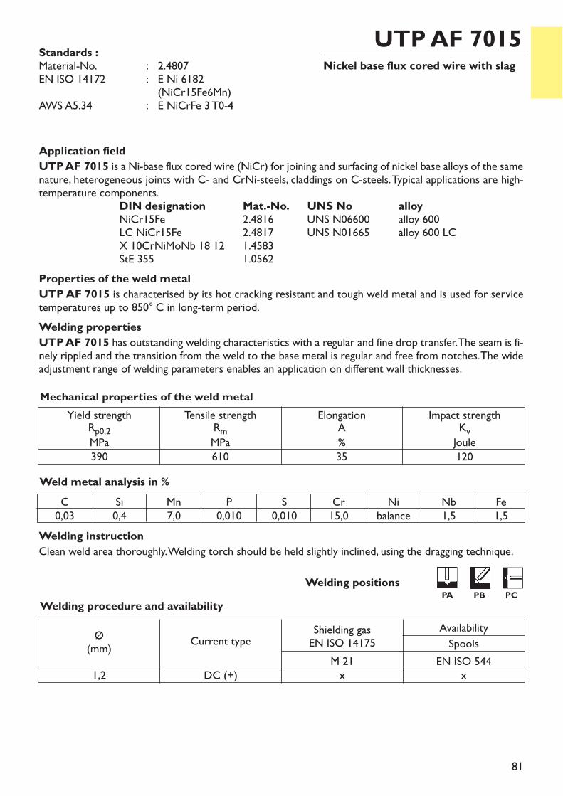
81
Nickel base flux cored wire with slagUTP AF 7015
Application fieldUTP AF 7015 is a Ni-base flux cored wire (NiCr) for joining and surfacing of nickel base alloys of the samenature, heterogeneous joints with C- and CrNi-steels, claddings on C-steels. Typical applications are high-temperature components.
DIN designation Mat.-No. UNS No alloyNiCr15Fe 2.4816 UNS N06600 alloy 600LC NiCr15Fe 2.4817 UNS N01665 alloy 600 LCX 10CrNiMoNb 18 12 1.4583StE 355 1.0562
Properties of the weld metalUTP AF 7015 is characterised by its hot cracking resistant and tough weld metal and is used for servicetemperatures up to 850° C in long-term period. Welding propertiesUTP AF 7015 has outstanding welding characteristics with a regular and fine drop transfer. The seam is fi-nely rippled and the transition from the weld to the base metal is regular and free from notches. The wideadjustment range of welding parameters enables an application on different wall thicknesses.
Welding instructionClean weld area thoroughly. Welding torch should be held slightly inclined, using the dragging technique.
Weld metal analysis in %
Yield strengthRp0,2MPa390
Tensile strengthRmMPa610
ElongationA%35
Impact strengthKvJoule120
Mechanical properties of the weld metal
Standards :Material-No. : 2.4807EN ISO 14172 : E Ni 6182
(NiCr15Fe6Mn)AWS A5.34 : E NiCrFe 3 T0-4
C0,03
Si0,4
Mn7,0
P0,010
S0,010
Cr15,0
Nibalance
Nb1,5
Fe1,5
Welding procedure and availability
Ø(mm) Current type Shielding gas
EN ISO 14175AvailabilitySpools
M 21 EN ISO 5441,2 DC (+) x x
Welding positionsPA PB PC
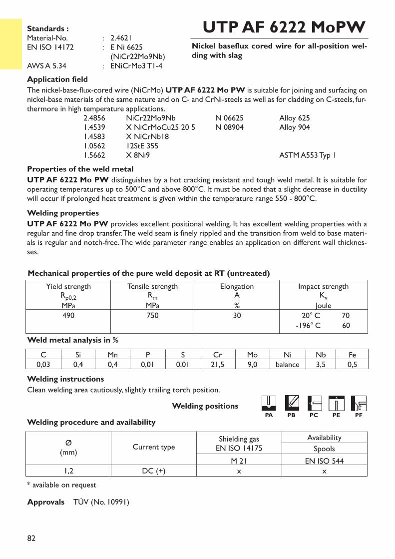
82
Nickel baseflux cored wire for all-position wel-ding with slag
UTP AF 6222 MoPW
Application fieldThe nickel-base-flux-cored wire (NiCrMo) UTP AF 6222 Mo PW is suitable for joining and surfacing onnickel-base materials of the same nature and on C- and CrNi-steels as well as for cladding on C-steels, fur-thermore in high temperature applications.
2.4856 NiCr22Mo9Nb N 06625 Alloy 6251.4539 X NiCrMoCu25 20 5 N 08904 Alloy 9041.4583 X NiCrNb18 1.0562 12StE 3551.5662 X 8Ni9 ASTM A553 Typ 1
Properties of the weld metalUTP AF 6222 Mo PW distinguishes by a hot cracking resistant and tough weld metal. It is suitable foroperating temperatures up to 500°C and above 800°C. It must be noted that a slight decrease in ductilitywill occur if prolonged heat treatment is given within the temperature range 550 - 800°C. Welding propertiesUTP AF 6222 Mo PW provides excellent positional welding. It has excellent welding properties with aregular and fine drop transfer. The weld seam is finely rippled and the transition from weld to base materi-als is regular and notch-free. The wide parameter range enables an application on different wall thicknes-ses.
Welding instructionsClean welding area cautiously, slightly trailing torch position.
Standards :Material-No. : 2.4621EN ISO 14172 : E Ni 6625
(NiCr22Mo9Nb) AWS A 5.34 : ENiCrMo3 T1-4
C0,03
Si0,4
Mn0,4
P0,01
S0,01
Cr21,5
Mo9,0
Nibalance
Nb3,5
Mechanical properties of the pure weld deposit at RT (untreated)Yield strengthRp0,2MPa
490
Tensile strengthRmMPa750
ElongationA%30
Impact strengthKvJoule20° C 70-196° C 60
Fe0,5
Welding procedure and availability
* available on request
Ø(mm) Current type Shielding gas
EN ISO 14175AvailabilitySpools
M 21 EN ISO 5441,2 DC (+) x x
Weld metal analysis in %
Approvals TÜV (No. 10991)
Welding positionsPA PB PC PE PF
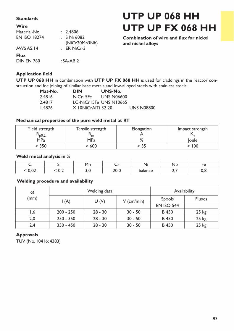
83
Application fieldUTP UP 068 HH in combination with UTP UP FX 068 HH is used for claddings in the reactor con-struction and for joining of similar base metals and low-alloyed steels with stainless steels:
Mat-No. DIN UNS-No.2.4816 NiCr15Fe UNS N066002.4817 LC-NiCr15Fe UNS N106651.4876 X 10NiCrAlTi 32 20 UNS N08800
Combination of wire and flux for nickeland nickel alloys
UTP UP 068 HHUTP UP FX 068 HH
StandardsWireMaterial-No. : 2.4806EN ISO 18274 : S Ni 6082
(NiCr20Mn3Nb)AWS A5.14 : ER NiCr-3FluxDIN EN 760 : SA-AB 2
Yield strengthRp0,2MPa> 350
Tensile strengthRmMPa> 600
ElongationA%> 35
Impact strengthKvJoule> 100
Mechanical properties of the pure weld metal at RT
ApprovalsTÜV (No. 10416; 4383)
Welding procedure and availabilityØ(mm)
Welding data AvailabilityI (A) U (V) V (cm/min) Spools Fluxes
EN ISO 5441,6 200 - 250 28 - 30 30 - 50 B 450 25 kg2,0 250 - 350 28 - 30 30 - 50 B 450 25 kg2,4 350 - 450 28 - 30 30 - 50 B 450 25 kg
C Si Mn Cr Ni Nb Fe< 0,02 < 0,2 3,0 20,0 balance 2,7 0,8
Weld metal analysis in %

84

85
86
87
Index
General wear protectionTool constructionCobalt hard alloys / Celsit
stick electrodessolid rods and wiresflux cored wireswires and flux for submerged-arc welding
Group 2Welding consumablesfor surfacing
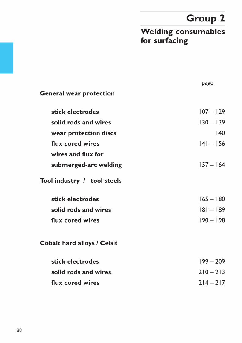
88
General wear protection
Tool industry / tool steels
Cobalt hard alloys / Celsit
stick electrodessolid rods and wireswear protection discsflux cored wireswires and flux for submerged-arc welding
107 – 129130 – 139
140141 – 156
157 – 164
page xxx
165 – 180181 – 189190 – 198
199 – 209210 – 213214 – 217
stick electrodessolid rods and wiresflux cored wires
stick electrodessolid rods and wiresflux cored wires
Group 2Welding consumablesfor surfacing
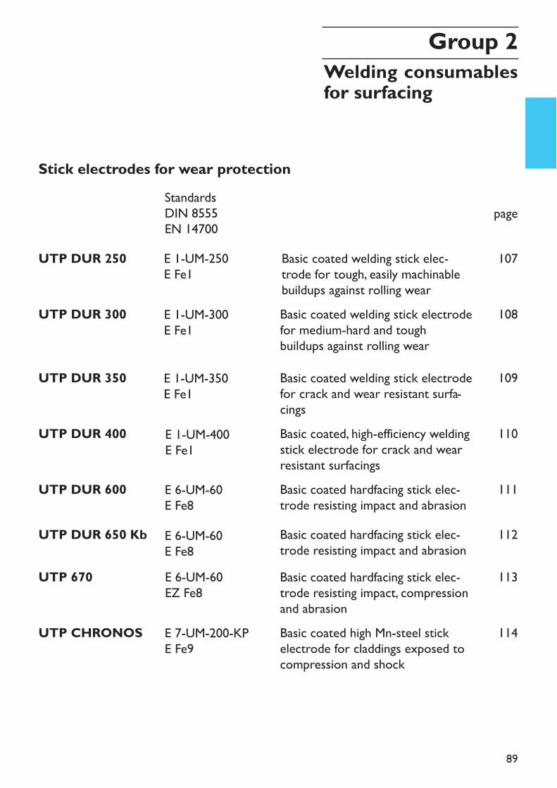
89
Stick electrodes for wear protection
page
UTP DUR 250 Basic coated welding stick elec-trode for tough, easily machinablebuildups against rolling wear
107
UTP DUR 300 Basic coated welding stick electrodefor medium-hard and tough buildups against rolling wear
108
UTP DUR 350 Basic coated welding stick electrodefor crack and wear resistant surfa-cings
109
UTP DUR 400 Basic coated, high-efficiency weldingstick electrode for crack and wearresistant surfacings
110
UTP DUR 600 Basic coated hardfacing stick elec-trode resisting impact and abrasion
111
UTP DUR 650 Kb Basic coated hardfacing stick elec-trode resisting impact and abrasion
112
UTP 670 Basic coated hardfacing stick elec-trode resisting impact, compressionand abrasion
113
114UTP CHRONOS Basic coated high Mn-steel stickelectrode for claddings exposed tocompression and shock
Group 2Welding consumablesfor surfacing
StandardsDIN 8555EN 14700E 1-UM-250E Fe1
E 1-UM-300E Fe1
E 1-UM-350E Fe1
E 1-UM-400E Fe1
E 6-UM-60E Fe8E 6-UM-60E Fe8E 6-UM-60EZ Fe8
E 7-UM-200-KPE Fe9
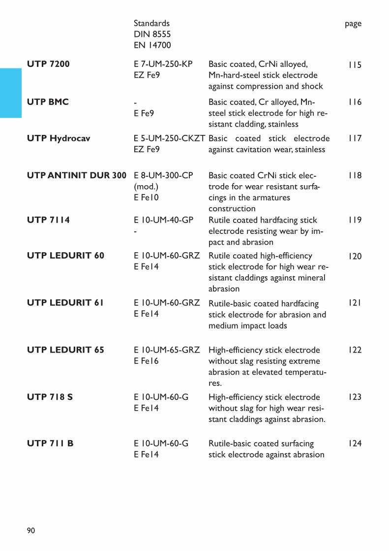
90
page
UTP 7200 Basic coated, CrNi alloyed, Mn-hard-steel stick electrodeagainst compression and shock
115
UTP ANTINIT DUR 300 Basic coated CrNi stick elec-trode for wear resistant surfa-cings in the armaturesconstruction
118
UTP BMC Basic coated, Cr alloyed, Mn-steel stick electrode for high re-sistant cladding, stainless
116
UTP 7114 Rutile coated hardfacing stickelectrode resisting wear by im-pact and abrasion
119
UTP LEDURIT 60 Rutile coated high-efficiencystick electrode for high wear re-sistant claddings against mineralabrasion
120
UTP LEDURIT 61 Rutile-basic coated hardfacingstick electrode for abrasion andmedium impact loads
121
UTP LEDURIT 65 High-efficiency stick electrodewithout slag resisting extremeabrasion at elevated temperatu-res.
122
UTP 711 B Rutile-basic coated surfacingstick electrode against abrasion
124
UTP 718 S High-efficiency stick electrodewithout slag for high wear resi-stant claddings against abrasion.
123
UTP Hydrocav Basic coated stick electrodeagainst cavitation wear, stainless
117
StandardsDIN 8555EN 14700
E 5-UM-250-CKZTEZ Fe9
E 7-UM-250-KPEZ Fe9
E 8-UM-300-CP(mod.)E Fe10
-E Fe9
E 10-UM-40-GP-E 10-UM-60-GRZE Fe14
E 10-UM-60-GRZE Fe14
E 10-UM-65-GRZE Fe16
E 10-UM-60-GE Fe14
E 10-UM-60-GE Fe14
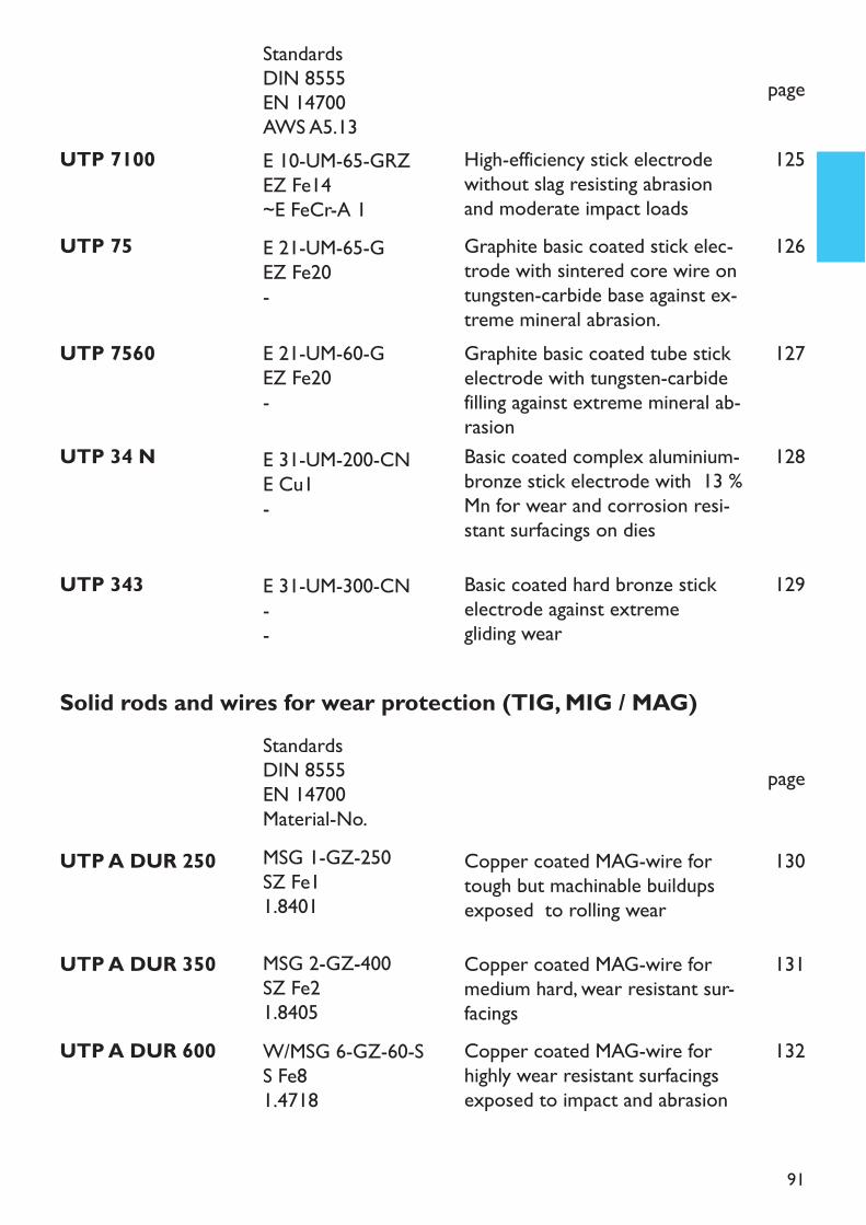
91
UTP 7560 Graphite basic coated tube stickelectrode with tungsten-carbidefilling against extreme mineral ab-rasion
page
127
UTP 34 N Basic coated complex aluminium-bronze stick electrode with 13 %Mn for wear and corrosion resi-stant surfacings on dies
128
UTP 75 Graphite basic coated stick elec-trode with sintered core wire ontungsten-carbide base against ex-treme mineral abrasion.
126
UTP 343 Basic coated hard bronze stickelectrode against extreme gliding wear
129
UTP A DUR 250 Copper coated MAG-wire fortough but machinable buildupsexposed to rolling wear
130
UTP A DUR 350 Copper coated MAG-wire formedium hard, wear resistant sur-facings
131
UTP A DUR 600 Copper coated MAG-wire forhighly wear resistant surfacingsexposed to impact and abrasion
132
Solid rods and wires for wear protection (TIG, MIG / MAG)
page
UTP 7100 High-efficiency stick electrodewithout slag resisting abrasionand moderate impact loads
125
E 21-UM-60-GEZ Fe20-
E 31-UM-200-CNE Cu1-
E 21-UM-65-GEZ Fe20-
E 31-UM-300-CN--
E 10-UM-65-GRZEZ Fe14~E FeCr-A 1
StandardsDIN 8555EN 14700AWS A5.13
StandardsDIN 8555EN 14700Material-No.MSG 1-GZ-250SZ Fe11.8401
MSG 2-GZ-400SZ Fe21.8405W/MSG 6-GZ-60-SS Fe81.4718
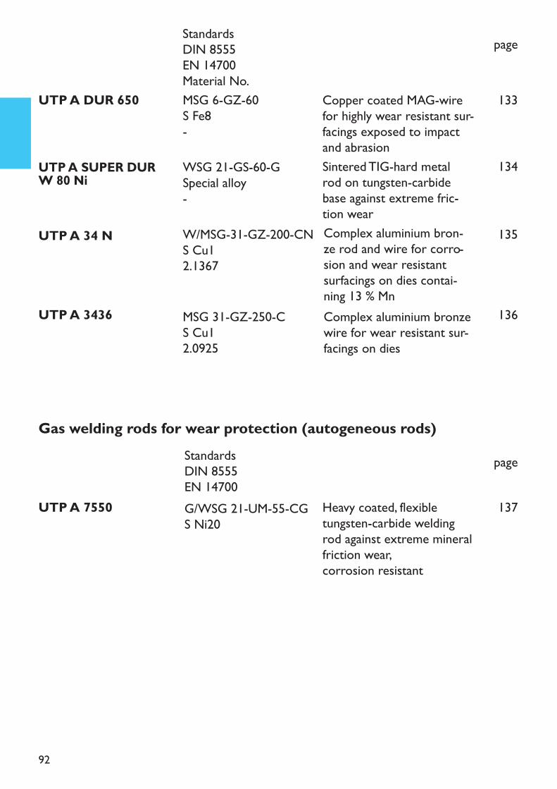
92
page
UTP A SUPER DUR W 80 NiSintered TIG-hard metalrod on tungsten-carbidebase against extreme fric-tion wear
134
UTP A 34 N Complex aluminium bron-ze rod and wire for corro-sion and wear resistantsurfacings on dies contai-ning 13 % Mn
135
UTP A 3436 Complex aluminium bronzewire for wear resistant sur-facings on dies
136
Gas welding rods for wear protection (autogeneous rods)page
UTP A 7550 Heavy coated, flexibletungsten-carbide weldingrod against extreme mineralfriction wear,corrosion resistant
137
UTP A DUR 650 Copper coated MAG-wirefor highly wear resistant sur-facings exposed to impactand abrasion
133
WSG 21-GS-60-GSpecial alloy-
W/MSG-31-GZ-200-CNS Cu12.1367
MSG 31-GZ-250-CS Cu12.0925
MSG 6-GZ-60S Fe8-
StandardsDIN 8555EN 14700Material No.
StandardsDIN 8555EN 14700G/WSG 21-UM-55-CGS Ni20
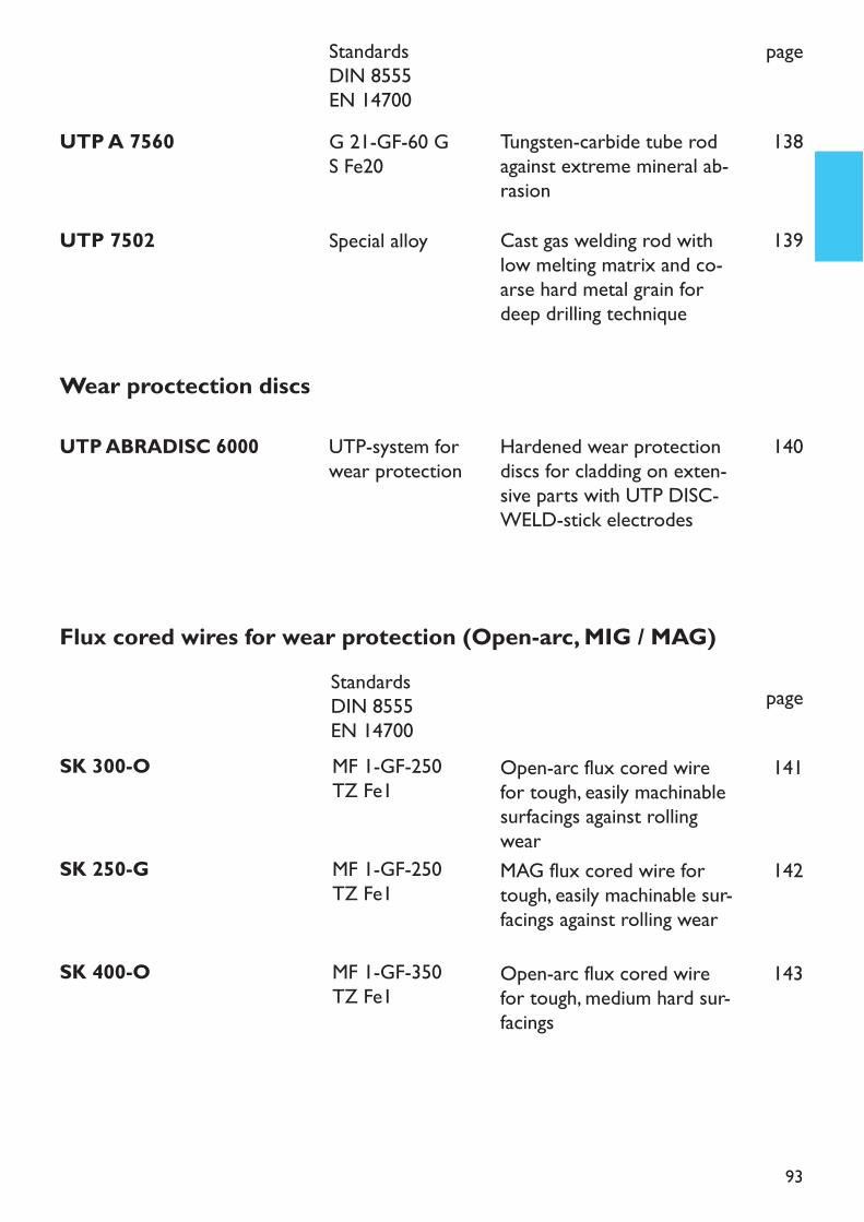
93
Wear proctection discs
UTP ABRADISC 6000 UTP-system forwear protection
Hardened wear protectiondiscs for cladding on exten-sive parts with UTP DISC-WELD-stick electrodes
140
page
Flux cored wires for wear protection (Open-arc, MIG / MAG)
Open-arc flux cored wirefor tough, easily machinablesurfacings against rollingwear
141
MAG flux cored wire fortough, easily machinable sur-facings against rolling wear
142
UTP 7502 Cast gas welding rod withlow melting matrix and co-arse hard metal grain fordeep drilling technique
139
UTP A 7560 Tungsten-carbide tube rodagainst extreme mineral ab-rasion
138
page
Open-arc flux cored wirefor tough, medium hard sur-facings
143
Special alloy
G 21-GF-60 GS Fe20
StandardsDIN 8555EN 14700
StandardsDIN 8555EN 14700MF 1-GF-250TZ Fe1
MF 1-GF-250TZ Fe1
MF 1-GF-350TZ Fe1
SK 300-O
SK 250-G
SK 400-O

94
page
Open-arc TiC-flux coredwire for wear resistantcladdings against compres-sion, impact and abrasion
148
MAG-TiC flux cored wirefor wear resistant claddingsagainst compression, impactand abrasion
149
Open-arc flux cored wirefor wear resistant build-upson high Mn-steel
150
Open-arc flux cored wirefor high wear resistantbuild-ups against extremecompressive, abrasive andimpact stresses
151
MAG flux cored wire fortough, medium hard surfa-cings
144
Open-arc flux cored wirefor highly wear resistantsurfacings
145
MAG flux cored wire fortough-hard and highly wearresistant surfacings
146
Open-arc flux cored wirefor highly wear resistantsurfacings
147SK 650-G
SK 258 TiC-O
SK 258 TiC-G
SK 218-O
SK AP-O
SK 350-G
SK 258-O
SK 600-G
StandardsDIN 8555EN 14700
MF 3-GF-60-GPT Fe8
MF 3-GF-60-STTZ Fe8
MF 10-GF-60-GPTZ Fe8
MF 7-GF-200-KPTZ Fe9MF 7-GF-250-KPTZ Fe9
MF 1-GF-350TZ Fe1
MF 4-GF-55-STT Fe8
MF 6-GF-60T Fe8
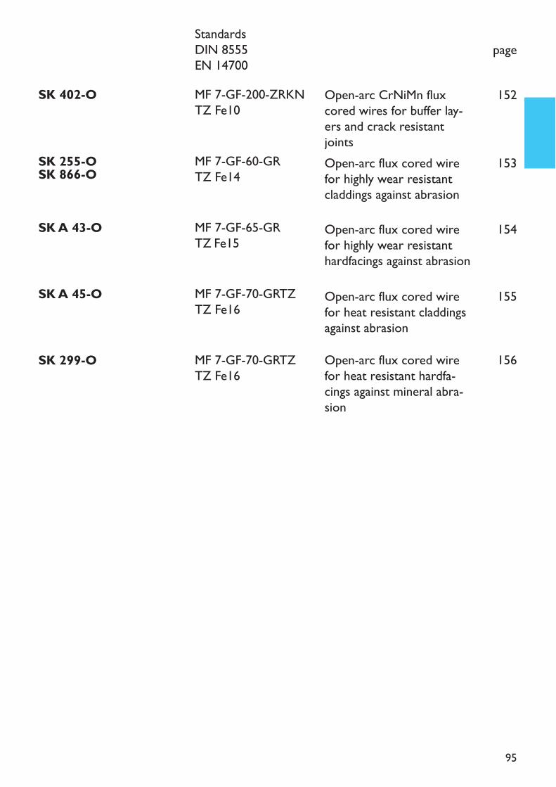
95
page
Open-arc flux cored wirefor heat resistant hardfa-cings against mineral abra-sion
156
Open-arc flux cored wirefor highly wear resistantcladdings against abrasion
153
Open-arc flux cored wirefor highly wear resistanthardfacings against abrasion
154
Open-arc flux cored wirefor heat resistant claddingsagainst abrasion
155
Open-arc CrNiMn fluxcored wires for buffer lay-ers and crack resistantjoints
152
SK 299-O
SK 255-OSK 866-O
SK A 43-O
SK A 45-O
SK 402-O
StandardsDIN 8555EN 14700
MF 7-GF-70-GRTZTZ Fe16
MF 7-GF-60-GRTZ Fe14
MF 7-GF-65-GRTZ Fe15
MF 7-GF-70-GRTZTZ Fe16
MF 7-GF-200-ZRKNTZ Fe10
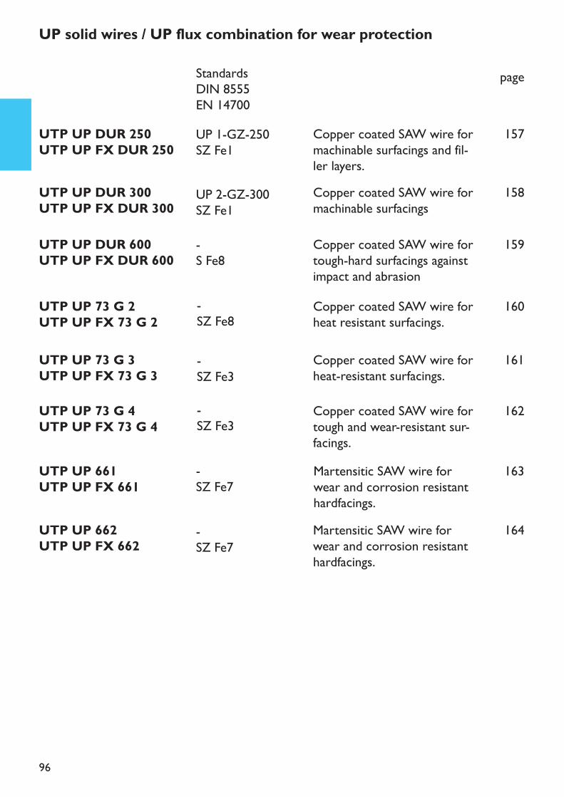
96
UTP UP 73 G 3UTP UP FX 73 G 3
Copper coated SAW wire forheat-resistant surfacings.
161
UTP UP 73 G 4UTP UP FX 73 G 4
Copper coated SAW wire fortough and wear-resistant sur-facings.
162
page
UTP UP DUR 250UTP UP FX DUR 250
Copper coated SAW wire formachinable surfacings and fil-ler layers.
157
UTP UP DUR 300UTP UP FX DUR 300
Copper coated SAW wire formachinable surfacings
158
UTP UP DUR 600UTP UP FX DUR 600
Copper coated SAW wire fortough-hard surfacings againstimpact and abrasion
159
UP solid wires / UP flux combination for wear protection
UTP UP 73 G 2UTP UP FX 73 G 2
Copper coated SAW wire forheat resistant surfacings.
160
UTP UP 662UTP UP FX 662
Martensitic SAW wire forwear and corrosion resistanthardfacings.
164
UTP UP 661UTP UP FX 661
163Martensitic SAW wire forwear and corrosion resistanthardfacings.
StandardsDIN 8555EN 14700UP 1-GZ-250SZ Fe1
UP 2-GZ-300SZ Fe1-S Fe8
-SZ Fe7
-SZ Fe7
-SZ Fe8
-SZ Fe3-SZ Fe3
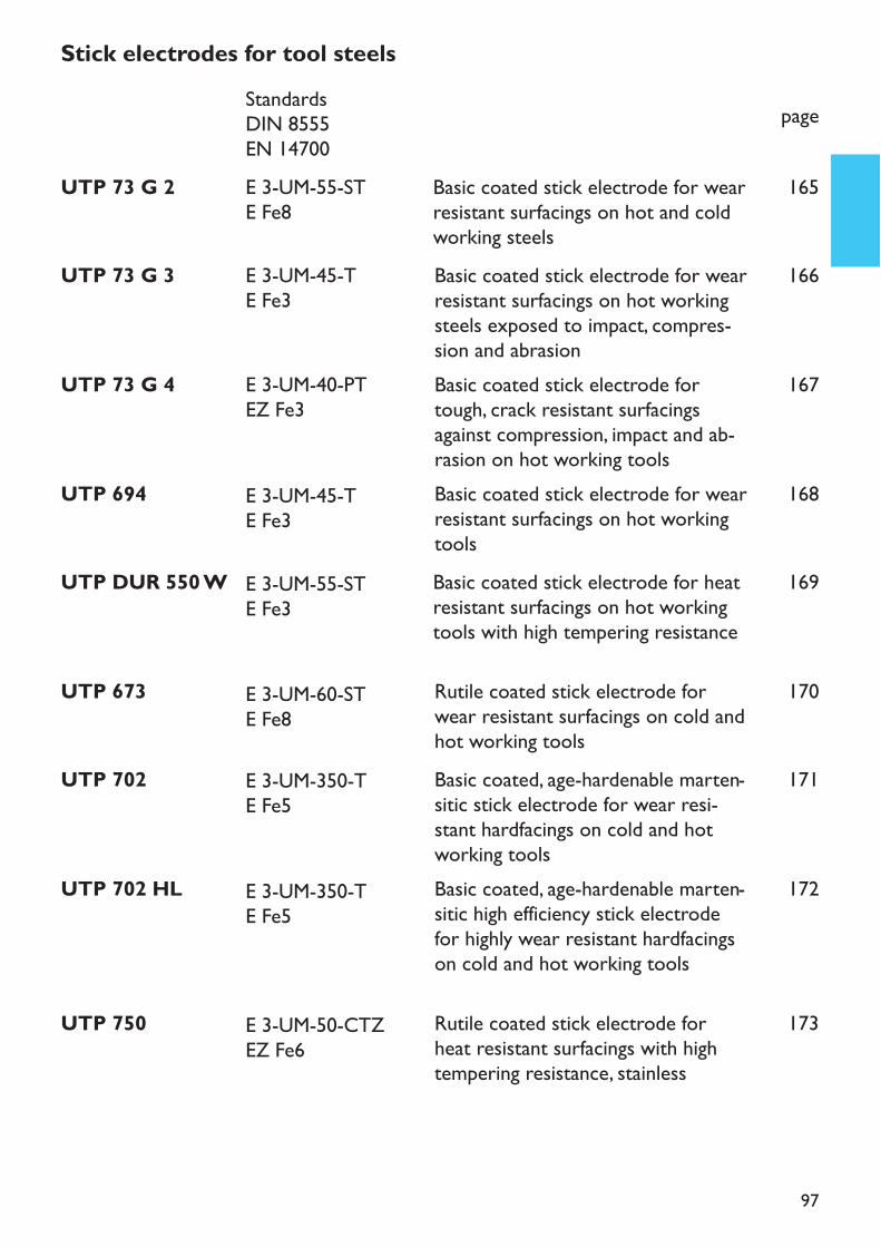
97
UTP 694 Basic coated stick electrode for wearresistant surfacings on hot workingtools
168
Stick electrodes for tool steels
page
UTP 73 G 2 Basic coated stick electrode for wearresistant surfacings on hot and coldworking steels
UTP 73 G 3 Basic coated stick electrode for wearresistant surfacings on hot workingsteels exposed to impact, compres-sion and abrasion
165
166
UTP 73 G 4 Basic coated stick electrode fortough, crack resistant surfacingsagainst compression, impact and ab-rasion on hot working tools
167
UTP DUR 550 W Basic coated stick electrode for heatresistant surfacings on hot workingtools with high tempering resistance
169
UTP 673 Rutile coated stick electrode forwear resistant surfacings on cold andhot working tools
170
UTP 702 Basic coated, age-hardenable marten-sitic stick electrode for wear resi-stant hardfacings on cold and hotworking tools
171
UTP 702 HL Basic coated, age-hardenable marten-sitic high efficiency stick electrodefor highly wear resistant hardfacingson cold and hot working tools
172
UTP 750 Rutile coated stick electrode forheat resistant surfacings with hightempering resistance, stainless
173
E 3-UM-45-TE Fe3
StandardsDIN 8555EN 14700E 3-UM-55-STE Fe8
E 3-UM-45-TE Fe3
E 3-UM-40-PTEZ Fe3
E 3-UM-55-STE Fe3
E 3-UM-60-STE Fe8
E 3-UM-350-TE Fe5
E 3-UM-350-TE Fe5
E 3-UM-50-CTZEZ Fe6
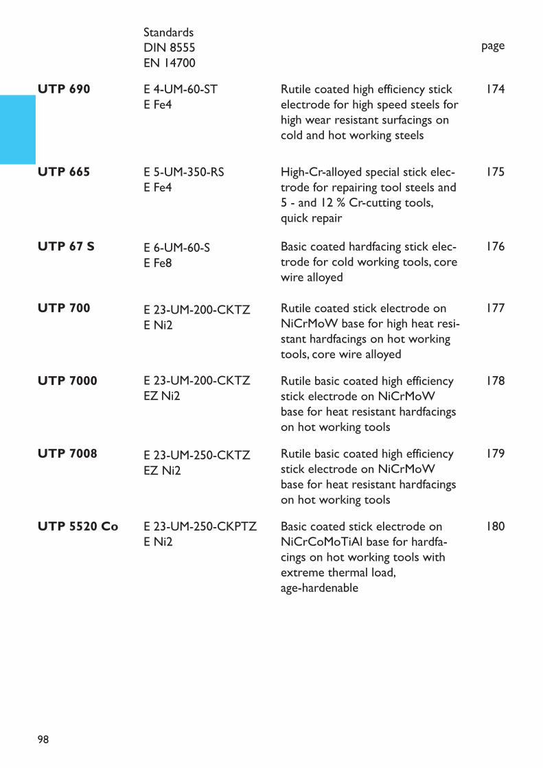
98
page
UTP 67 S Basic coated hardfacing stick elec-trode for cold working tools, corewire alloyed
176
UTP 700 Rutile coated stick electrode onNiCrMoW base for high heat resi-stant hardfacings on hot workingtools, core wire alloyed
177
UTP 7000 Rutile basic coated high efficiencystick electrode on NiCrMoWbase for heat resistant hardfacingson hot working tools
178
UTP 7008 Rutile basic coated high efficiencystick electrode on NiCrMoWbase for heat resistant hardfacingson hot working tools
179
UTP 5520 Co Basic coated stick electrode onNiCrCoMoTiAl base for hardfa-cings on hot working tools withextreme thermal load, age-hardenable
180
UTP 665 High-Cr-alloyed special stick elec-trode for repairing tool steels and 5 - and 12 % Cr-cutting tools,quick repair
175
UTP 690 Rutile coated high efficiency stickelectrode for high speed steels forhigh wear resistant surfacings oncold and hot working steels
174
StandardsDIN 8555EN 14700
E 6-UM-60-SE Fe8
E 23-UM-200-CKTZE Ni2
E 23-UM-200-CKTZEZ Ni2
E 23-UM-250-CKTZEZ Ni2
E 23-UM-250-CKPTZE Ni2
E 5-UM-350-RSE Fe4
E 4-UM-60-STE Fe4
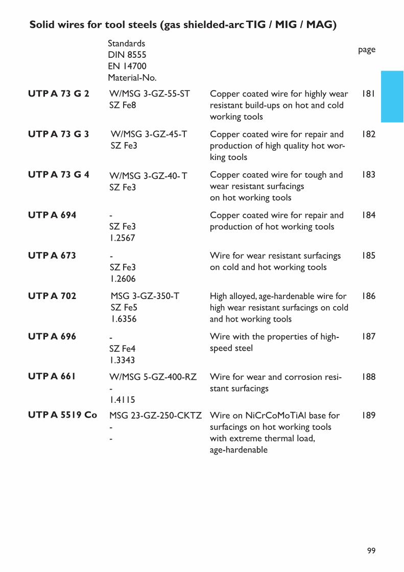
99
UTP A 696 Wire with the properties of high-speed steel
187
UTP A 702 High alloyed, age-hardenable wire forhigh wear resistant surfacings on coldand hot working tools
186
UTP A 5519 Co Wire on NiCrCoMoTiAl base forsurfacings on hot working toolswith extreme thermal load,age-hardenable
189
UTP A 661 Wire for wear and corrosion resi-stant surfacings
188
UTP A 694 Copper coated wire for repair andproduction of hot working tools
184
UTP A 673 Wire for wear resistant surfacingson cold and hot working tools
185
Solid wires for tool steels (gas shielded-arc TIG / MIG / MAG)page
UTP A 73 G 2 Copper coated wire for highly wearresistant build-ups on hot and coldworking tools
181
UTP A 73 G 3 Copper coated wire for repair andproduction of high quality hot wor-king tools
182
UTP A 73 G 4 Copper coated wire for tough andwear resistant surfacings on hot working tools
183
-SZ Fe41.3343
MSG 3-GZ-350-TSZ Fe51.6356
MSG 23-GZ-250-CKTZ--
W/MSG 5-GZ-400-RZ-1.4115
-SZ Fe31.2567-SZ Fe31.2606
StandardsDIN 8555EN 14700Material-No.W/MSG 3-GZ-55-STSZ Fe8
W/MSG 3-GZ-45-TSZ Fe3
W/MSG 3-GZ-40- TSZ Fe3
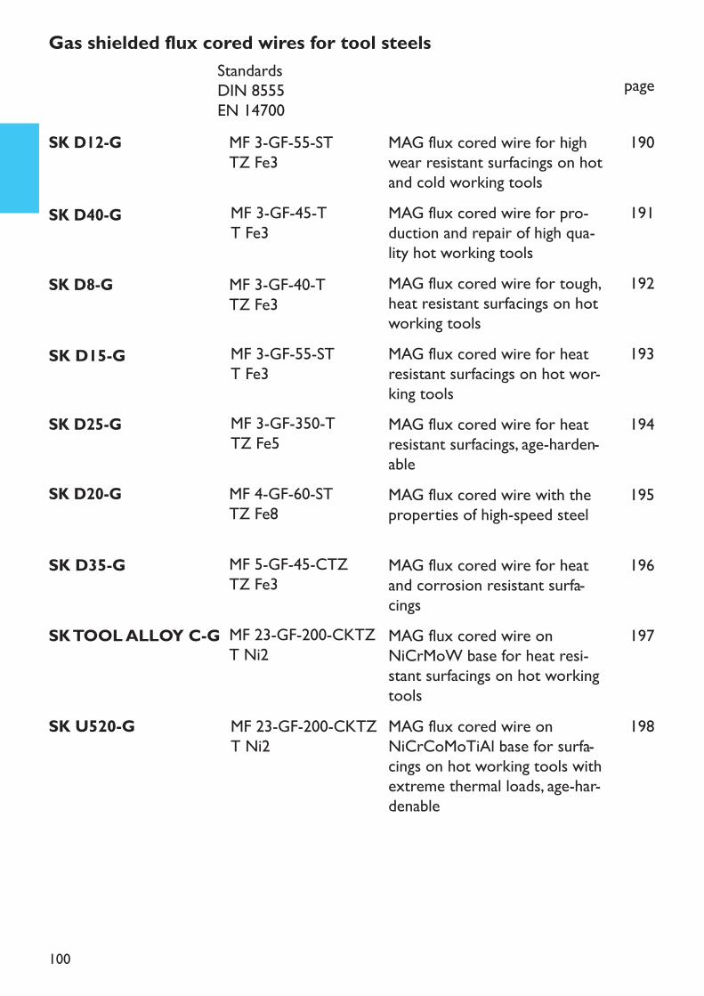
100
MAG flux cored wire for heatand corrosion resistant surfa-cings
196
MAG flux cored wire onNiCrCoMoTiAl base for surfa-cings on hot working tools withextreme thermal loads, age-har-denable
198
MAG flux cored wire onNiCrMoW base for heat resi-stant surfacings on hot workingtools
197
MAG flux cored wire for heatresistant surfacings, age-harden-able
194
Gas shielded flux cored wires for tool steelspage
MAG flux cored wire for tough,heat resistant surfacings on hotworking tools
192
MAG flux cored wire for highwear resistant surfacings on hotand cold working tools
190
MAG flux cored wire for pro-duction and repair of high qua-lity hot working tools
191
MAG flux cored wire for heatresistant surfacings on hot wor-king tools
193
MAG flux cored wire with theproperties of high-speed steel
195
SK D35-G
SK U520-G
SK TOOL ALLOY C-G
SK D25-G
SK D8-G
SK D12-G
SK D40-G
SK D15-G
SK D20-G
MF 5-GF-45-CTZTZ Fe3
MF 23-GF-200-CKTZT Ni2
MF 23-GF-200-CKTZT Ni2
MF 3-GF-350-TTZ Fe5
StandardsDIN 8555EN 14700
MF 3-GF-40-TTZ Fe3
MF 3-GF-55-STTZ Fe3
MF 3-GF-45-TT Fe3
MF 3-GF-55-STT Fe3
MF 4-GF-60-STTZ Fe8
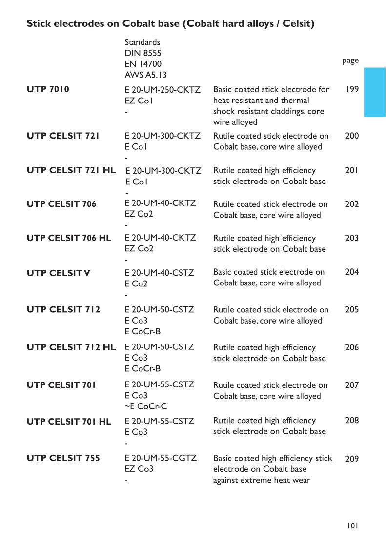
101
UTP CELSIT 712 Rutile coated stick electrode onCobalt base, core wire alloyed
205
UTP CELSIT 712 HL Rutile coated high efficiencystick electrode on Cobalt base
206
UTP CELSIT 701 Rutile coated stick electrode onCobalt base, core wire alloyed
207
UTP CELSIT 701 HL Rutile coated high efficiencystick electrode on Cobalt base
208
UTP CELSIT 755 Basic coated high efficiency stickelectrode on Cobalt baseagainst extreme heat wear
209
UTP CELSIT 706 Rutile coated stick electrode onCobalt base, core wire alloyed
202
UTP CELSIT 706 HL Rutile coated high efficiencystick electrode on Cobalt base
203
Stick electrodes on Cobalt base (Cobalt hard alloys / Celsit)
page
UTP 7010 Basic coated stick electrode forheat resistant and thermalshock resistant claddings, corewire alloyed
199
UTP CELSIT 721 Rutile coated stick electrode onCobalt base, core wire alloyed
200
UTP CELSIT 721 HL Rutile coated high efficiencystick electrode on Cobalt base
201
UTP CELSIT V Basic coated stick electrode onCobalt base, core wire alloyed
204
E 20-UM-50-CSTZE Co3E CoCr-BE 20-UM-50-CSTZE Co3E CoCr-BE 20-UM-55-CSTZE Co3~E CoCr-CE 20-UM-55-CSTZE Co3-E 20-UM-55-CGTZEZ Co3-
E 20-UM-40-CKTZEZ Co2-E 20-UM-40-CKTZEZ Co2-
StandardsDIN 8555EN 14700AWS A5.13E 20-UM-250-CKTZEZ Co1-E 20-UM-300-CKTZE Co1-E 20-UM-300-CKTZE Co1-
E 20-UM-40-CSTZE Co2-
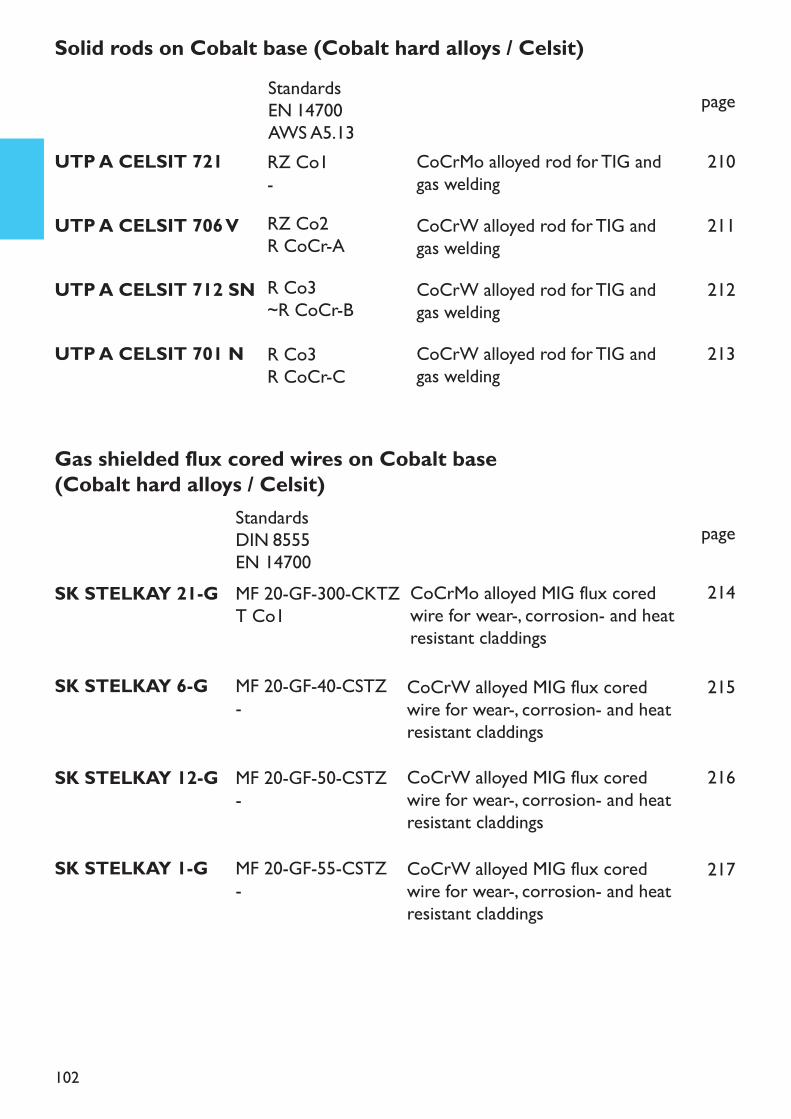
102
UTP A CELSIT 701 N CoCrW alloyed rod for TIG andgas welding
213
UTP A CELSIT 712 SN CoCrW alloyed rod for TIG andgas welding
212
Gas shielded flux cored wires on Cobalt base (Cobalt hard alloys / Celsit)
page
CoCrMo alloyed MIG flux coredwire for wear-, corrosion- and heatresistant claddings
214
CoCrW alloyed MIG flux coredwire for wear-, corrosion- and heatresistant claddings
215
CoCrW alloyed MIG flux coredwire for wear-, corrosion- and heatresistant claddings
216
CoCrW alloyed MIG flux coredwire for wear-, corrosion- and heatresistant claddings
217
Solid rods on Cobalt base (Cobalt hard alloys / Celsit)page
UTP A CELSIT 721 CoCrMo alloyed rod for TIG andgas welding
210
UTP A CELSIT 706 V CoCrW alloyed rod for TIG andgas welding
211
R Co3R CoCr-C
R Co3~R CoCr-B
StandardsEN 14700AWS A5.13RZ Co1-RZ Co2R CoCr-A
StandardsDIN 8555EN 14700MF 20-GF-300-CKTZT Co1
MF 20-GF-40-CSTZ-
MF 20-GF-50-CSTZ-
MF 20-GF-55-CSTZ-
SK STELKAY 21-G
SK STELKAY 6-G
SK STELKAY 12-G
SK STELKAY 1-G
103
GeneralWelding consumables for building up are, corresponding to their analysis, divided inthe following alloy groups (according to DIN 8555):
– Fe-base (alloy group 1 – 10)– Co- and Ni-base (alloy group 20 – 23)– Cu-base (alloy group 30 – 32)
WEAR is, technically spoken, an undesired change of a surface appearance, due to– Abrasion– Corrosion (rust, scale)– Cavitation– Erosion
Wear does not have to be limited to one only reason. It can be a combination of se-veral reasons such as mechanical abrasion and corrosion. The hardness is the measu-ring unit for the wear resistance of an alloy. Hardness comparison is only possiblewithin the same alloy group. The common hardness measuring systems are:
–Test according to Brinell DIN EN ISO 6506-1– (for soft and massive materials)–Test according to Rockwell C DIN EN ISO 6508-1– (for hard and massive materials)–Test according to Vickers DIN EN ISO 6507-1– (for hard and soft, thick and – thin materials; very exact)
UTP welding consumables for tool steels(production and repair)Hot working tools
Fe-base UTP 73 G 2, UTP 73 G 3, UTP 73 G 4, UTP 702, UTP 65 D, UTP 653, UTP 6020 plus the corresponding MIG wires and TIG rodsCo-base UTP CELSIT 701, UTP CELSIT 706, UTP CELSIT 712, UTP 7010, UTP CELSIT 721 plus the corresponding MIG wires and TIG rods
1.
•
•
2.
2.1
Hardsurfacing with UTP welding consumables
• Ni-base UTP 700, UTP 7000, UTP 7008, UTP 6222 Mo, UTP 7015 Mo plus the corre-sponding MIG wires and TIG rods
104
Crack weldingCrack must be gouged out completely in tulip form by either UTP 82 AS, milling orgrinding. Large and heavy tools should be pre-heated for gouging and welding at 250– 400° C.Suitable UTP stick electrodes: UTP 6020, UTP 653, UTP 7015 Mo, UTP 6222 Mo.When welding with UTP 6020 or UTP 653, the final layers con be of an Fe- or aCo-base hard material. If the crack is being welded with Ni-base stick electrodesUTP 7015 Mo or UTP 6222 Mo, the final layers have to be made with Ni- or Co-base hard materials.Build up weldingThe selection of the welding consumable is depending on the type and size of wear.Due to the fact that UTP stick electrodes are available in various hardness degrees,the most suitable can be selected to obtain the best results for cutting tools, man-drels or engravings. The service live obtained after welding is generally longer thanthat of a new tool.Tempered tools have to be pre-heated at 400 – 600° C and this temperature shouldbe maintained during the welding process. This is specially important for filling ofengravings, where large welding deposits have to be made.
Small (cosmetic) repairs on tempered tools can be made without or with little localpre-heating. 1 – 2 layers should be deposited as a maximum and the deposit has tobe penned thoroughly.UTP 65 D, UTP 665, UTP A 641Larger repairs on heat treated tools need a preheating and interpass temperatureof 480° C.For production of new cutting tools on low alloy base material, a preheating ofabout 150 – 250° C is sufficient.UTP 67 S, UTP 673, UTP 690, UTP 73 G 2Major repairs and changes of patterns of a tool should be made in soft annealedcondition and welded with a consumable similar to the alloy of the base metal.The preheat and interpass temperature should be approx. 450° C.UTP 673, UTP 67 S
a)
b)
a)
b)
c)
Cold working tools2.2
105
2.3 High-speed steel toolsRepair weldingMinor repairs on cutting tools as for example: dulling or decomposing (bleeding)of the material, can be easily performed by using low preheating temperatures upto 150°C. This preheating temperature is sufficient as long as the defect does notaffect the base material. A maximum of 1 - 2 layers are applicable.In bigger repairs, for example broken teeth down to the base material, a constant(universal) preheating to 400 - 600°C is necessary. The same procedure is neces-sary in build ups of a larger working surface. In both cases, a thorough hammeringof the weld bead has to be applied followed by low cooling.UTP 690, UTP A 696Joint weldingDuring the weld joining process of ruptured or broken cutting tools constant pre-heating temperatures to 450 - 600 °C are necessary. Welding of short seams haveto be hammered immediately because of stress drop. Slow cooling.UTP 65 D, UTP 653, UTP A 651
a)
b)
2.4 Plastic form steelsPlastic form steels are suitable for the production of form design tools in the pla-stic processing industry. Unalloyed steels, application steels and tool steels can beapplied. Due to their special degree of purity, the good polishing ability, hardness re-gularity and structure, temperature and stress resistance and a good thermal con-ductivity, these form steels possess an excellent usability. Depending on the plasticmaterial which is being used, corrosion resistance may be required as well.These steels are optimally and individually adjustable to the requirements of thetool respectively the plastic product.Weld filler materials are applied mainly of the same composition as the base. Thewelding properties of the steel and the used filler metals have to be separately ted-ted before application.In surfacing treated tools (carburising, nitriding), the hardened layer must be re-moved, at first. A suitable welding rod for particular repairs is the TIG rod UTP A 702.
106
UTP welding consumables for surfacing against grinding wearBuffer layerUTP 63, UTP 630, UTP 6302Hard surfacingUTP 67 S, UTP 670, UTP DUR 600, UTP 7200, UTP LEDURIT 61, UTP 711 B, UTP 7100, UTP 75 plus the corresponding flux cored wires.Substantial and high wear resistant surfacings (max. 3 layers) have to be made on topof a buffer layer (soft, tough) and with eventual inter layers (tough-hard), to prevent thatalloy typical stress relieve cracks are reaching into the base material.Base materials susceptible to a hardness increase (high C-steel) should be pre-heatedat 150 – 300° C.
UTP welding consumables for surfacing against gliding wear(metal to metal)Surfacing with aluminium complex bronzes on steel have proven, due to their excel-lent friction coefficient, to be very suitable on drawing tools and forming dies.UTP 34 N, UTP 343, UTP A 3436
Anti wear system of UTP against mineral wear UTP ABRADISC 6000Hardened wear protection discs such as UTP ABRADISC 6000 are sufaced onto largeweldments in order to prevent a mineral friction wear. The surfacing process is carriedout dependant on the stress strain direction with the special stick electrodes UTPDICSWELD according to the given sample. Main application fields are: shovels, slides(chutes), mixers and large wear areas on caterpillars and construction machines (en-gines).
3.
4.
Instead of the traditional melting process, these steels are not being molten, but highsensitive powders are sintered under pressure and temperature to a homgeneousand sintered material. Due to the high strength, ductility, fatigue resistance, pressureresistance and thermal resistance as well as wear resistance such materials have anoutstanding quality. In general, these materials are considered to be difficult to weld.If the material is being welded, nevertheless, some of the special mechanical pro-perties get lost because the weld pool solidifies in a weld seam with a cast struc-ture.
2.5 Flux metallurgic fabricated steels
5.
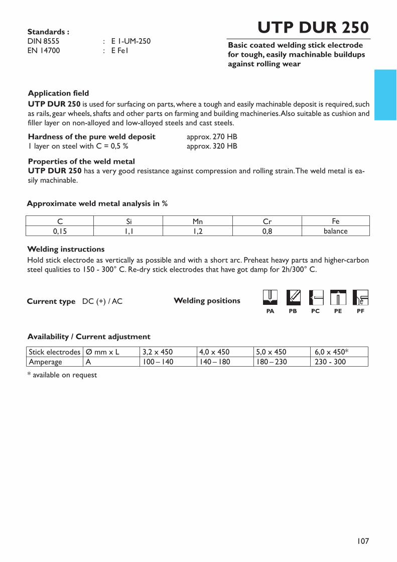
107
Basic coated welding stick electrodefor tough, easily machinable buildupsagainst rolling wear
UTP DUR 250
Welding instructionsHold stick electrode as vertically as possible and with a short arc. Preheat heavy parts and higher-carbonsteel qualities to 150 - 300° C. Re-dry stick electrodes that have got damp for 2h/300° C.
Application fieldUTP DUR 250 is used for surfacing on parts, where a tough and easily machinable deposit is required, suchas rails, gear wheels, shafts and other parts on farming and building machineries. Also suitable as cushion andfiller layer on non-alloyed and low-alloyed steels and cast steels. Hardness of the pure weld deposit approx. 270 HB1 layer on steel with C = 0,5 % approx. 320 HBProperties of the weld metalUTP DUR 250 has a very good resistance against compression and rolling strain. The weld metal is ea-sily machinable.
Approximate weld metal analysis in %
Availability / Current adjustment
Current type DC (+) / AC
Standards :DIN 8555 : E 1-UM-250EN 14700 : E Fe1
C0,15
Si1,1
Mn1,2
Cr0,8
Febalance
Stick electrodesAmperage
Ø mm x LA
3,2 x 450100 – 140
4,0 x 450140 – 180
5,0 x 450180 – 230
6,0 x 450*230 - 300
* available on request
Welding positionsPA PB PC PE PF
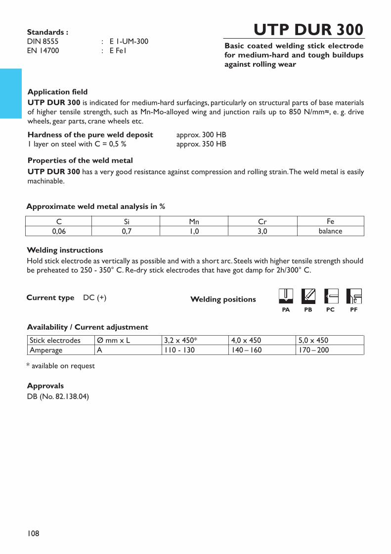
108
Basic coated welding stick electrodefor medium-hard and tough buildupsagainst rolling wear
UTP DUR 300
Welding instructionsHold stick electrode as vertically as possible and with a short arc. Steels with higher tensile strength shouldbe preheated to 250 - 350° C. Re-dry stick electrodes that have got damp for 2h/300° C.
Standards :DIN 8555 : E 1-UM-300EN 14700 : E Fe1
Application fieldUTP DUR 300 is indicated for medium-hard surfacings, particularly on structural parts of base materialsof higher tensile strength, such as Mn-Mo-alloyed wing and junction rails up to 850 N/mm≈, e. g. drivewheels, gear parts, crane wheels etc.Hardness of the pure weld deposit approx. 300 HB1 layer on steel with C = 0,5 % approx. 350 HBProperties of the weld metalUTP DUR 300 has a very good resistance against compression and rolling strain. The weld metal is easilymachinable.
Approximate weld metal analysis in %
Availability / Current adjustment
Current type DC (+)
C0,06
Si0,7
Mn1,0
Cr3,0
Febalance
* available on request
Stick electrodesAmperage
Ø mm x LA
3,2 x 450*110 - 130
4,0 x 450140 – 160
5,0 x 450170 – 200
Welding positionsPA PB PC PF
ApprovalsDB (No. 82.138.04)
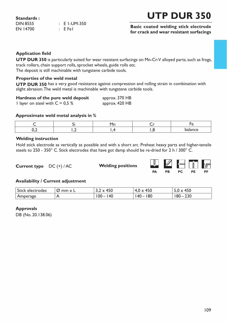
109
Basic coated welding stick electrodefor crack and wear resistant surfacings
UTP DUR 350
Welding instructionHold stick electrode as vertically as possible and with a short arc. Preheat heavy parts and higher-tensilesteels to 250 - 350° C. Stick electrodes that have got damp should be re-dried for 2 h / 300° C.
Application fieldUTP DUR 350 is particularly suited for wear resistant surfacings on Mn-Cr-V alloyed parts, such as frogs,track rollers, chain support rolls, sprocket wheels, guide rolls etc.The deposit is still machinable with tungstene carbide tools. Properties of the weld metalUTP DUR 350 has a very good resistance against compression and rolling strain in combination withslight abrasion. The weld metal is machinable with tungstene carbide tools.Hardness of the pure weld deposit approx. 370 HB1 layer on steel with C = 0,5 % approx. 420 HBApproximate weld metal analysis in %
Availability / Current adjustmentStick electrodesAmperage
Ø mm x LA
3,2 x 450100 – 140
4,0 x 450140 – 180
5,0 x 450180 – 230
Current type DC (+) / AC
C0,2
Si1,2
Mn1,4
Cr1,8
Febalance
Standards :DIN 8555 : E 1-UM-350EN 14700 : E Fe1
ApprovalsDB (No. 20.138.06)
Welding positionsPA PB PC PE PF
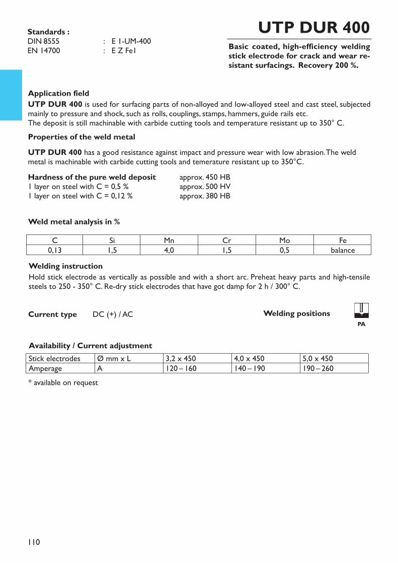
110
Basic coated, high-efficiency weldingstick electrode for crack and wear re-sistant surfacings. Recovery 200 %.
UTP DUR 400
Welding instructionHold stick electrode as vertically as possible and with a short arc. Preheat heavy parts and high-tensilesteels to 250 - 350° C. Re-dry stick electrodes that have got damp for 2 h / 300° C.
* available on request
Application fieldUTP DUR 400 is used for surfacing parts of non-alloyed and low-alloyed steel and cast steel, subjectedmainly to pressure and shock, such as rolls, couplings, stamps, hammers, guide rails etc.The deposit is still machinable with carbide cutting tools and temperature resistant up to 350° C. Properties of the weld metalUTP DUR 400 has a good resistance against impact and pressure wear with low abrasion. The weldmetal is machinable with carbide cutting tools and temerature resistant up to 350°C.Hardness of the pure weld deposit approx. 450 HB1 layer on steel with C = 0,5 % approx. 500 HV1 layer on steel with C = 0,12 % approx. 380 HB
Weld metal analysis in %
Availability / Current adjustment
Current type DC (+) / AC
Standards :DIN 8555 : E 1-UM-400EN 14700 : E Z Fe1
C0,13
Si1,5
Mn4,0
Cr1,5
Mo0,5
Febalance
Stick electrodesAmperage
Ø mm x LA
3,2 x 450120 – 160
4,0 x 450140 – 190
5,0 x 450190 – 260
Welding positionsPA
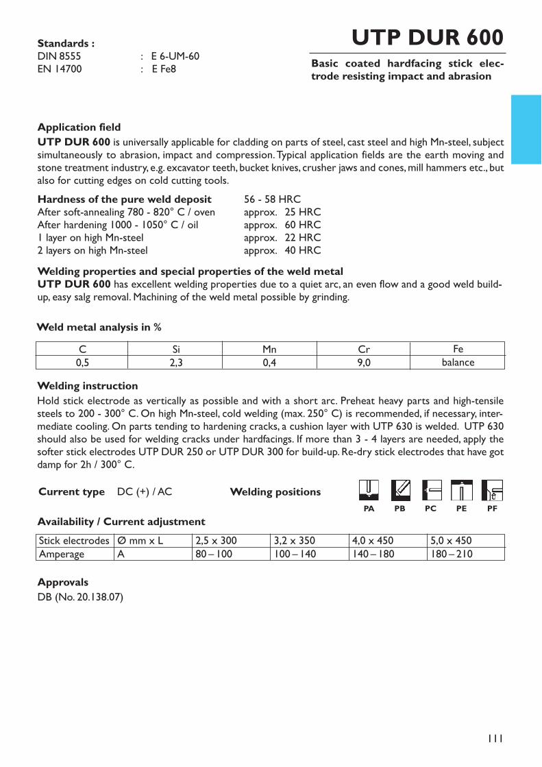
111
Basic coated hardfacing stick elec-trode resisting impact and abrasion
UTP DUR 600
Welding instructionHold stick electrode as vertically as possible and with a short arc. Preheat heavy parts and high-tensilesteels to 200 - 300° C. On high Mn-steel, cold welding (max. 250° C) is recommended, if necessary, inter-mediate cooling. On parts tending to hardening cracks, a cushion layer with UTP 630 is welded. UTP 630should also be used for welding cracks under hardfacings. If more than 3 - 4 layers are needed, apply thesofter stick electrodes UTP DUR 250 or UTP DUR 300 for build-up. Re-dry stick electrodes that have gotdamp for 2h / 300° C.
Application fieldUTP DUR 600 is universally applicable for cladding on parts of steel, cast steel and high Mn-steel, subjectsimultaneously to abrasion, impact and compression. Typical application fields are the earth moving andstone treatment industry, e.g. excavator teeth, bucket knives, crusher jaws and cones, mill hammers etc., butalso for cutting edges on cold cutting tools. Hardness of the pure weld deposit 56 - 58 HRCAfter soft-annealing 780 - 820° C / oven approx. 25 HRCAfter hardening 1000 - 1050° C / oil approx. 60 HRC1 layer on high Mn-steel approx. 22 HRC2 layers on high Mn-steel approx. 40 HRCWelding properties and special properties of the weld metalUTP DUR 600 has excellent welding properties due to a quiet arc, an even flow and a good weld build-up, easy salg removal. Machining of the weld metal possible by grinding.
Weld metal analysis in %
Availability / Current adjustment
Current type DC (+) / AC
Standards :DIN 8555 : E 6-UM-60EN 14700 : E Fe8
C0,5
Si2,3
Mn0,4
Cr9,0
Febalance
4,0 x 450140 – 180
Stick electrodesAmperage
Ø mm x LA
2,5 x 30080 – 100
3,2 x 350100 – 140
5,0 x 450180 – 210
ApprovalsDB (No. 20.138.07)
Welding positionsPA PB PC PE PF
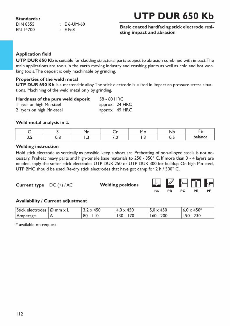
112
Basic coated hardfacing stick electrode resi-sting impact and abrasion
UTP DUR 650 Kb
Welding instructionHold stick electrode as vertically as possible, keep a short arc. Preheating of non-alloyed steels is not ne-cessary. Preheat heavy parts and high-tensile base materials to 250 - 350° C. If more than 3 - 4 layers areneeded, apply the softer stick electrodes UTP DUR 250 or UTP DUR 300 for buildup. On high Mn-steel,UTP BMC should be used. Re-dry stick electrodes that have got damp for 2 h / 300° C.
Application fieldUTP DUR 650 Kb is suitable for cladding structural parts subject to abrasion combined with impact. Themain applications are tools in the earth moving industry and crushing plants as well as cold and hot wor-king tools. The deposit is only machinable by grinding.Properties of the weld metalUTP DUR 650 Kb is a martensitic alloy. The stick electrode is suited in impact an pressure stress situa-tions. Machining of the weld metal only by grinding.Hardness of the pure weld deposit 58 - 60 HRC1 layer on high Mn-steel approx. 24 HRC2 layers on high Mn-steel approx. 45 HRCWeld metal analysis in %
Availability / Current adjustment
Current type DC (+) / AC
* available on request
Standards :DIN 8555 : E 6-UM-60EN 14700 : E Fe8
C0,5
Si0,8
Mn1,3
Cr7,0
Mo1,3
Nb0,5
Febalance
Stick electrodesAmperage
Ø mm x LA
3,2 x 45080 – 110
4,0 x 450130 – 170
5,0 x 450160 – 200
6,0 x 450*190 – 230
Welding positionsPA PB PC PE PF

113
Basic coated hardfacing stick elec-trode resisting impact, compressionand abrasion
UTP 670
Welding instructionHold stick electrode as vertically as possible and keep a short arc. Preheating is generally not neces-sary.For multipass applications it is advisable to weld cushion layers with UTP DUR 250 and to apply UTP 670for the last 3 layers. Preheating temperature of high Mn-steels should not exceed 250° C, if necessary in-termediate cooling or welding in a water bath. Stick electrodes that have got damp should be redried for2 h / 300° C.
Application fieldUTP 670 is a high-efficiency stick electrode for hardfacing workpieces of steel, cast steel or high Mn-steel,subject to simultaneous wear by impact, compression and abrasion. Due to its recovery, this stick electrodeis ideally suited for economic one-layer applications. Typical applications are crane wheels, rollers, chainlinks, sprocket wheels, gliding surfaces, screw conveyors, beaters, edge runners, guide wheels, baffle platesetc.Properties of the weld metalUTP 670 has a martensitic structure and is suited for impact and compression wear and slight abrasion.Hardness of the pure weld deposit approx. 58 HRCWeld metal analysis in %
Availability / Current adjustment
Current type DC (+) / AC
* available on request
Standards :DIN 8555 : E 6-UM-60EN 14700 : EZ Fe8
C0,4
Si1,0
Mn1,0
Cr9,5
Mo0,6
V1,5
Febalance
Stick electrodesAmperage
Ø mm x LA
2,5 x 350*70 – 90
3,2 x 45090 – 120
4,0 x 450130 – 160
5,0 x 450170 – 210
Welding positionsPA PB PC PF
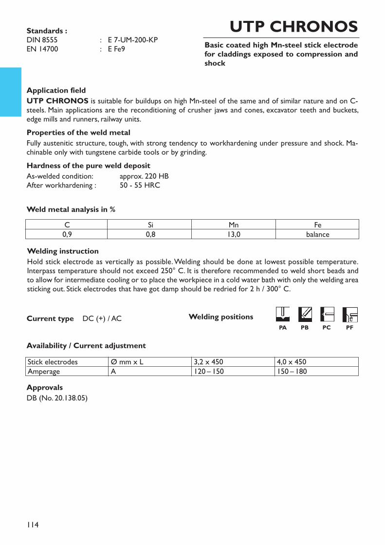
114
Basic coated high Mn-steel stick electrodefor claddings exposed to compression andshock
UTP CHRONOS
Welding instructionHold stick electrode as vertically as possible. Welding should be done at lowest possible temperature.Interpass temperature should not exceed 250° C. It is therefore recommended to weld short beads andto allow for intermediate cooling or to place the workpiece in a cold water bath with only the welding areasticking out. Stick electrodes that have got damp should be redried for 2 h / 300° C.
Application fieldUTP CHRONOS is suitable for buildups on high Mn-steel of the same and of similar nature and on C-steels. Main applications are the reconditioning of crusher jaws and cones, excavator teeth and buckets,edge mills and runners, railway units.Properties of the weld metalFully austenitic structure, tough, with strong tendency to workhardening under pressure and shock. Ma-chinable only with tungstene carbide tools or by grinding.Hardness of the pure weld depositAs-welded condition: approx. 220 HBAfter workhardening : 50 - 55 HRC
Weld metal analysis in %
Availability / Current adjustment
Current type DC (+) / AC
Standards : DIN 8555 : E 7-UM-200-KPEN 14700 : E Fe9
C0,9
Si0,8
Mn13,0
Febalance
Stick electrodesAmperage
Ø mm x LA
3,2 x 450120 – 150
4,0 x 450150 – 180
ApprovalsDB (No. 20.138.05)
Welding positionsPA PB PC PF
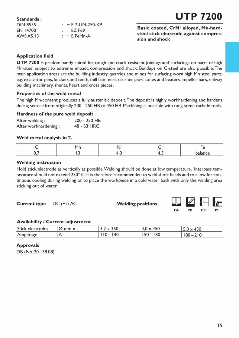
115
Basic coated, CrNi alloyed, Mn-hard-steel stick electrode against compres-sion and shock
UTP 7200
Welding instructionHold stick electrode as vertically as possible. Welding should be done at low temperature. Interpass tem-perature should not exceed 250° C. It is therefore recommended to weld short beads and to allow for con-tinuous cooling during welding or to place the workpiece in a cold water bath with only the welding areasticking out of water.
Application fieldUTP 7200 is predominantly suited for tough and crack resistant joinings and surfacings on parts of highMn-steel subject to extreme impact, compression and shock. Buildups on C-steel are also possible. Themain application areas are the building industry, quarries and mines for surfacing worn high Mn steel parts,e.g. excavator pins, buckets and teeth, mill hammers, crusher jaws, cones and beaters, impeller bars, railwaybuilding machinery, shunts, heart and cross pieces.Properties of the weld metalThe high Mn-content produces a fully austenitic deposit. The deposit is highly workhardening and hardensduring service from originally 200 - 250 HB to 450 HB. Machining is possible with tung-stene carbide tools.Hardness of the pure weld depositAfter welding : 200 - 250 HBAfter workhardening : 48 - 53 HRCWeld metal analysis in %
C0,7
Mn13
Ni4,0
Cr4,5
Febalance
Availability / Current adjustment
Current type DC (+) / AC
Stick electrodesAmperage
Ø mm x LA
3,2 x 350110 – 140
4,0 x 450150 – 180
5,0 x 450180 – 210
Standards :DIN 8555 : ~ E 7-UM-250-KPEN 14700 : ~ EZ Fe9AWS A5.13 : ~ E FeMn-A
ApprovalsDB (No. 20.138.08)
Welding positionsPA PB PC PF
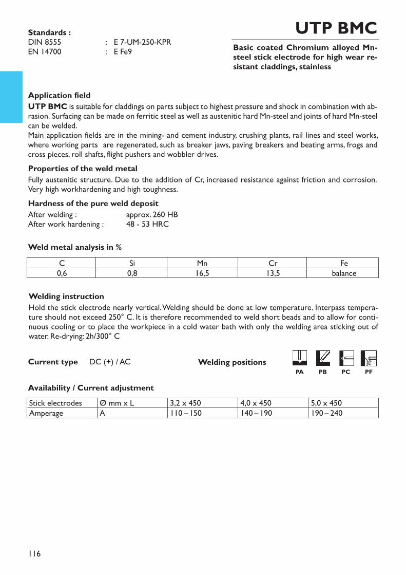
116
Basic coated Chromium alloyed Mn-steel stick electrode for high wear re-sistant claddings, stainless
UTP BMC
Welding instructionHold the stick electrode nearly vertical. Welding should be done at low temperature. Interpass tempera-ture should not exceed 250° C. It is therefore recommended to weld short beads and to allow for conti-nuous cooling or to place the workpiece in a cold water bath with only the welding area sticking out ofwater. Re-drying: 2h/300° C
Application fieldUTP BMC is suitable for claddings on parts subject to highest pressure and shock in combination with ab-rasion. Surfacing can be made on ferritic steel as well as austenitic hard Mn-steel and joints of hard Mn-steelcan be welded.Main application fields are in the mining- and cement industry, crushing plants, rail lines and steel works,where working parts are regenerated, such as breaker jaws, paving breakers and beating arms, frogs andcross pieces, roll shafts, flight pushers and wobbler drives.Properties of the weld metalFully austenitic structure. Due to the addition of Cr, increased resistance against friction and corrosion.Very high workhardening and high toughness.Hardness of the pure weld depositAfter welding : approx. 260 HBAfter work hardening : 48 - 53 HRC
Weld metal analysis in %C0,6
Si0,8
Mn16,5
Cr13,5
Febalance
Availability / Current adjustment
Current type DC (+) / AC
Stick electrodesAmperage
Ø mm x LA
3,2 x 450110 – 150
4,0 x 450140 – 190
5,0 x 450190 – 240
Standards :DIN 8555 : E 7-UM-250-KPREN 14700 : E Fe9
Welding positionsPA PB PC PF
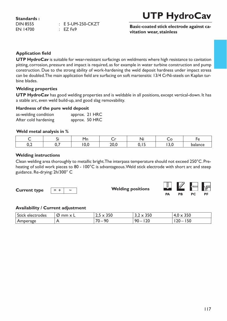
117
Basic-coated stick electrode against ca-vitation wear, stainless
UTP HydroCav
Welding instructionsClean welding area thoroughly to metallic bright. The interpass temperature should not exceed 250°C. Pre-heating of solid work pieces to 80 - 100°C is advantageous. Weld stick electrode with short arc and steepguidance. Re-drying: 2h/300° C
Availability / Current adjustment
Standards :DIN 8555 : E 5-UM-250-CKZTEN 14700 : EZ Fe9
Application fieldUTP HydroCav is suitable for wear-resistant surfacings on weldments where high resistance to cavitationpitting, corrosion, pressure and impact is required, as for example in water turbine construction and pumpconstruction. Due to the strong ability of work-hardening the weld deposit hardness under impact stresscan be doubled. The main application field are surfacing on soft martensitic 13/4 CrNi-steels on Kaplan tur-bine blades.Welding propertiesUTP HydroCav has good welding properties and is weldable in all positions, except vertical-down. It hasa stable arc, even weld build-up, and good slag removability.Hardness of the pure weld depositas-welding condition approx. 21 HRCAfter cold hardening approx. 50 HRCWeld metal analysis in %
C0,2
Si0,7
Mn10,0
Cr20,0
Ni0,15
Co13,0
Febalance
Stick electrodesAmperage
Ø mm x LA
2,5 x 35070 – 90
3,2 x 35090 – 120
4,0 x 350120 – 150
Current type = + ~ Welding positionsPA PB PC PF
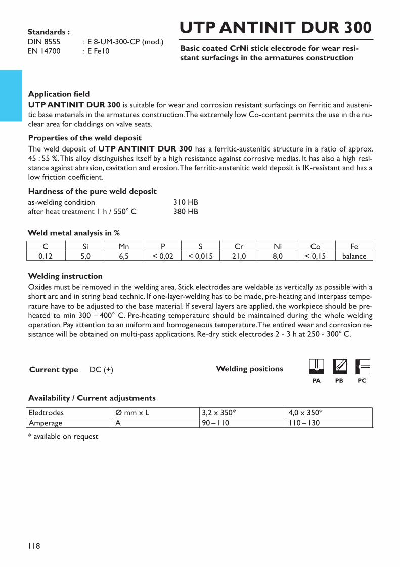
118
Basic coated CrNi stick electrode for wear resi-stant surfacings in the armatures construction
UTP ANTINIT DUR 300
Welding instructionOxides must be removed in the welding area. Stick electrodes are weldable as vertically as possible with ashort arc and in string bead technic. If one-layer-welding has to be made, pre-heating and interpass tempe-rature have to be adjusted to the base material. If several layers are applied, the workpiece should be pre-heated to min 300 – 400° C. Pre-heating temperature should be maintained during the whole weldingoperation. Pay attention to an uniform and homogeneous temperature. The entired wear and corrosion re-sistance will be obtained on multi-pass applications. Re-dry stick electrodes 2 - 3 h at 250 - 300° C.
* available on request
Current type DC (+)
Application fieldUTP ANTINIT DUR 300 is suitable for wear and corrosion resistant surfacings on ferritic and austeni-tic base materials in the armatures construction. The extremely low Co-content permits the use in the nu-clear area for claddings on valve seats.Properties of the weld depositThe weld deposit of UTP ANTINIT DUR 300 has a ferritic-austenitic structure in a ratio of approx. 45 : 55 %. This alloy distinguishes itself by a high resistance against corrosive medias. It has also a high resi-stance against abrasion, cavitation and erosion. The ferritic-austenitic weld deposit is IK-resistant and has alow friction coefficient.Hardness of the pure weld depositas-welding condition 310 HBafter heat treatment 1 h / 550° C 380 HBWeld metal analysis in %
Availability / Current adjustments
Standards :DIN 8555 : E 8-UM-300-CP (mod.)EN 14700 : E Fe10
C0,12
Si5,0
Mn6,5
P< 0,02
S< 0,015
Cr21,0
Ni8,0
Co< 0,15
Febalance
EledtrodesAmperage
Ø mm x LA
3,2 x 350*90 – 110
4,0 x 350*110 – 130
Welding positionsPA PB PC
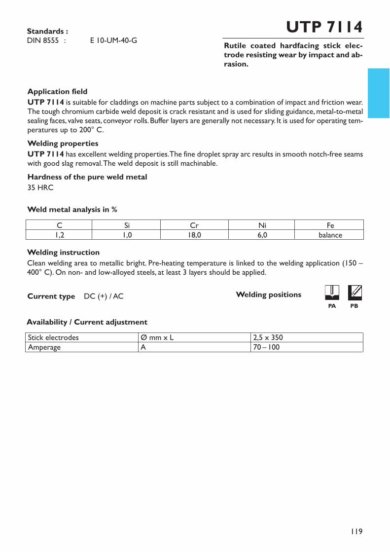
119
Rutile coated hardfacing stick elec-trode resisting wear by impact and ab-rasion.
UTP 7114
Welding instructionClean welding area to metallic bright. Pre-heating temperature is linked to the welding application (150 –400° C). On non- and low-alloyed steels, at least 3 layers should be applied.
Application fieldUTP 7114 is suitable for claddings on machine parts subject to a combination of impact and friction wear.The tough chromium carbide weld deposit is crack resistant and is used for sliding guidance, metal-to-metalsealing faces, valve seats, conveyor rolls. Buffer layers are generally not necessary. It is used for operating tem-peratures up to 200° C.Welding propertiesUTP 7114 has excellent welding properties. The fine droplet spray arc results in smooth notch-free seamswith good slag removal. The weld deposit is still machinable.Hardness of the pure weld metal35 HRC
Weld metal analysis in %
Availability / Current adjustment
Current type DC (+) / AC
Standards :DIN 8555 : E 10-UM-40-G
C1,2
Si1,0
Cr18,0
Ni6,0
Febalance
Stick electrodesAmperage
Ø mm x LA
2,5 x 35070 – 100
Welding positions PA PB
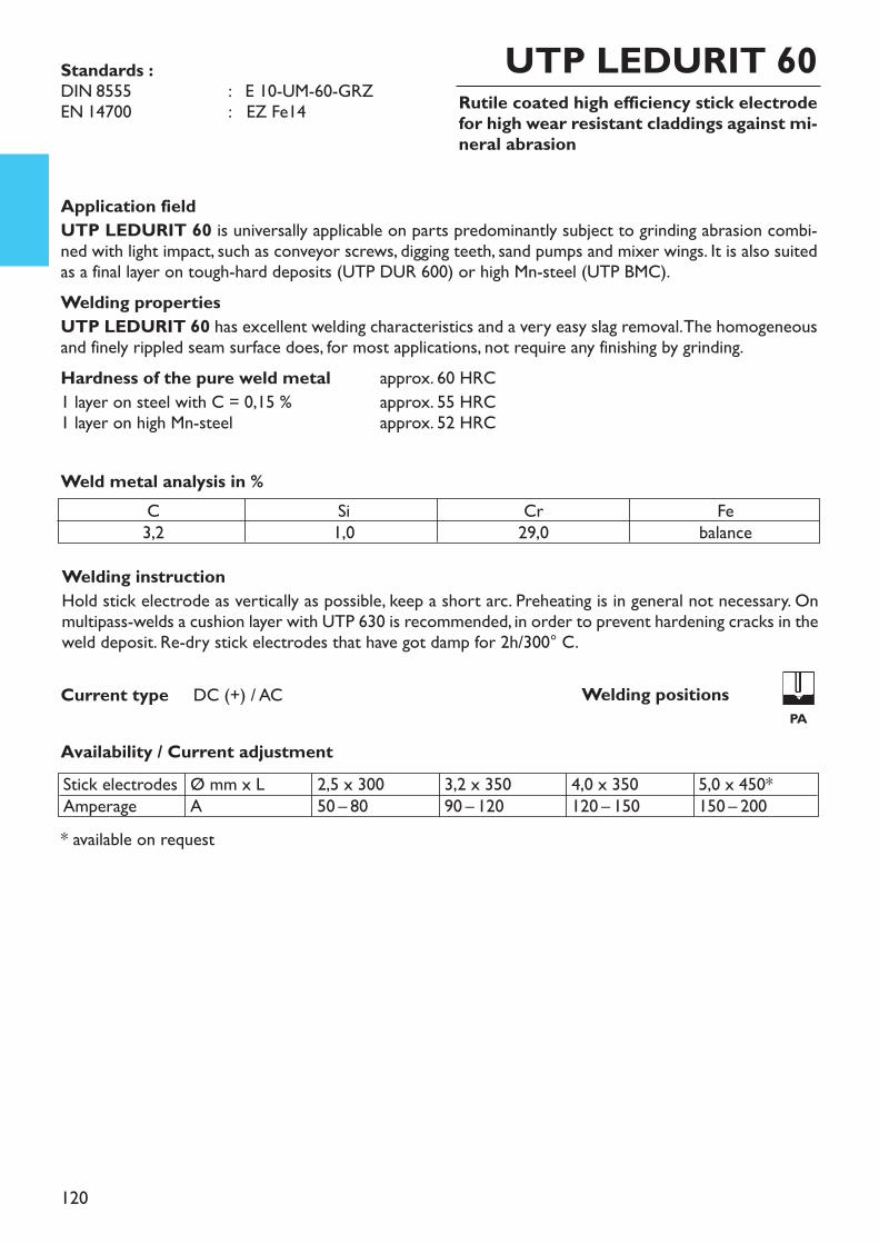
120
Rutile coated high efficiency stick electrodefor high wear resistant claddings against mi-neral abrasion
UTP LEDURIT 60
Welding instructionHold stick electrode as vertically as possible, keep a short arc. Preheating is in general not necessary. Onmultipass-welds a cushion layer with UTP 630 is recommended, in order to prevent hardening cracks in theweld deposit. Re-dry stick electrodes that have got damp for 2h/300° C.
Application fieldUTP LEDURIT 60 is universally applicable on parts predominantly subject to grinding abrasion combi-ned with light impact, such as conveyor screws, digging teeth, sand pumps and mixer wings. It is also suitedas a final layer on tough-hard deposits (UTP DUR 600) or high Mn-steel (UTP BMC).Welding propertiesUTP LEDURIT 60 has excellent welding characteristics and a very easy slag removal. The homogeneousand finely rippled seam surface does, for most applications, not require any finishing by grinding.Hardness of the pure weld metal approx. 60 HRC1 layer on steel with C = 0,15 % approx. 55 HRC1 layer on high Mn-steel approx. 52 HRC
Weld metal analysis in %C3,2
Si1,0
Cr29,0
Febalance
Availability / Current adjustment
Current type DC (+) / AC
* available on request
Standards : DIN 8555 : E 10-UM-60-GRZEN 14700 : EZ Fe14
Stick electrodesAmperage
Ø mm x LA
2,5 x 30050 – 80
3,2 x 35090 – 120
4,0 x 350120 – 150
5,0 x 450*150 – 200
Welding positions PA
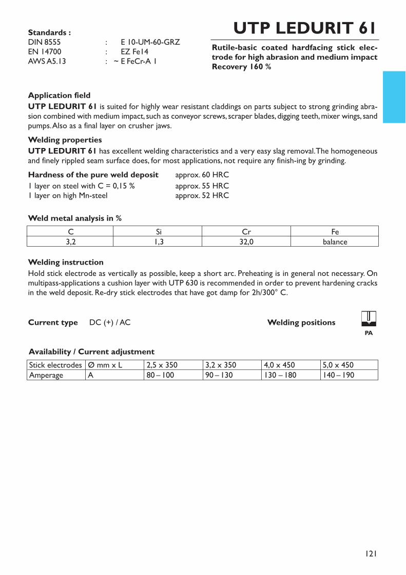
121
Rutile-basic coated hardfacing stick elec-trode for high abrasion and medium impactRecovery 160 %
UTP LEDURIT 61
Welding instructionHold stick electrode as vertically as possible, keep a short arc. Preheating is in general not necessary. Onmultipass-applications a cushion layer with UTP 630 is recommended in order to prevent hardening cracksin the weld deposit. Re-dry stick electrodes that have got damp for 2h/300° C.
Application fieldUTP LEDURIT 61 is suited for highly wear resistant claddings on parts subject to strong grinding abra-sion combined with medium impact, such as conveyor screws, scraper blades, digging teeth, mixer wings, sandpumps. Also as a final layer on crusher jaws.Welding propertiesUTP LEDURIT 61 has excellent welding characteristics and a very easy slag removal. The homogeneousand finely rippled seam surface does, for most applications, not require any finish-ing by grinding.Hardness of the pure weld deposit approx. 60 HRC1 layer on steel with C = 0,15 % approx. 55 HRC1 layer on high Mn-steel approx. 52 HRC
Weld metal analysis in %C3,2
Si1,3
Cr32,0
Febalance
Availability / Current adjustment
Current type DC (+) / AC
Stick electrodesAmperage
Ø mm x LA
2,5 x 35080 – 100
3,2 x 35090 – 130
4,0 x 450130 – 180
5,0 x 450140 – 190
Standards :DIN 8555 : ~ E 10-UM-60-GRZEN 14700 : ~ EZ Fe14AWS A5.13 : ~ E FeCr-A 1
Welding positions PA
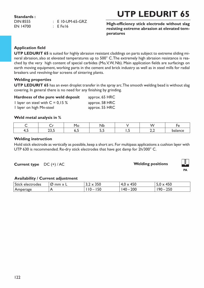
122
High-efficiency stick electrode without slagresisting extreme abrasion at elevated tem-peratures
UTP LEDURIT 65
Welding instructionHold stick electrode as vertically as possible, keep a short arc. For multipass applications a cushion layer withUTP 630 is recommended. Re-dry stick electrodes that have got damp for 2h/300° C.
Application fieldUTP LEDURIT 65 is suited for highly abrasion resistant claddings on parts subject to extreme sliding mi-neral abrasion, also at elevated temperatures up to 500° C. The extremely high abrasion resistance is rea-ched by the very high content of special carbides (Mo, V, W, Nb). Main application fields are surfacings onearth moving equipment, working parts in the cement and brick industry as well as in steel mills for radialbreakers und revolving-bar screens of sintering plants.Welding propertiesUTP LEDURIT 65 has an even droplet transfer in the spray arc. The smooth welding bead is without slagcovering. In general there is no need for any finishing by grinding.Hardness of the pure weld deposit approx. 65 HRC1 layer on steel with C = 0,15 % approx. 58 HRC1 layer on high Mn-steel approx. 55 HRCWeld metal analysis in %
Availability / Current adjustment
Current type DC (+) / AC
Stick electrodesAmperage
Ø mm x LA
3,2 x 350110 – 150
4,0 x 450140 – 200
5,0 x 450190 – 250
Standards : DIN 8555 : E 10-UM-65-GRZEN 14700 : E Fe16
C4,5
Cr23,5
Mo6,5
Nb5,5
V1,5
W2,2
Febalance
Welding positionsPA
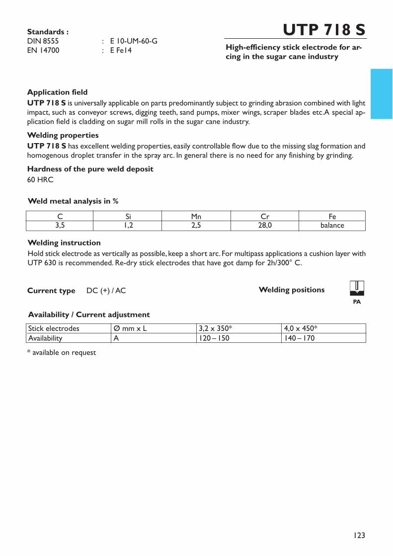
123
High-efficiency stick electrode for ar-cing in the sugar cane industry
UTP 718 S
Welding instructionHold stick electrode as vertically as possible, keep a short arc. For multipass applications a cushion layer withUTP 630 is recommended. Re-dry stick electrodes that have got damp for 2h/300° C.
* available on request
Application fieldUTP 718 S is universally applicable on parts predominantly subject to grinding abrasion combined with lightimpact, such as conveyor screws, digging teeth, sand pumps, mixer wings, scraper blades etc.A special ap-plication field is cladding on sugar mill rolls in the sugar cane industry.Welding propertiesUTP 718 S has excellent welding properties, easily controllable flow due to the missing slag formation andhomogenous droplet transfer in the spray arc. In general there is no need for any finishing by grinding.Hardness of the pure weld deposit60 HRCWeld metal analysis in %
Availability / Current adjustment
Current type DC (+) / AC
Standards :DIN 8555 : E 10-UM-60-GEN 14700 : E Fe14
C3,5 Si1,2 Mn2,5 Cr28,0 Febalance
Stick electrodesAvailability
Ø mm x LA
3,2 x 350*120 – 150
4,0 x 450*140 – 170
Welding positions PA
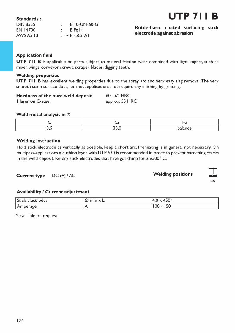
124
Rutile-basic coated surfacing stickelectrode against abrasion
Welding instructionHold stick electrode as vertically as possible, keep a short arc. Preheating is in general not necessary. Onmultipass-applications a cushion layer with UTP 630 is recommended in order to prevent hardening cracksin the weld deposit. Re-dry stick electrodes that have got damp for 2h/300° C.
* available on request
UTP 711 B
Application fieldUTP 711 B is applicable on parts subject to mineral friction wear combined with light impact, such asmixer wings, conveyor screws, scraper blades, digging teeth.Welding propertiesUTP 711 B has excellent welding properties due to the spray arc and very easy slag removal. The verysmooth seam surface does, for most applications, not require any finishing by grinding.Hardness of the pure weld deposit 60 - 62 HRC1 layer on C-steel approx. 55 HRC
Weld metal analysis in %C3,5
Cr35,0
Febalance
Availability / Current adjustment
Current type DC (+) / AC
Standards :DIN 8555 : ~ E 10-UM-60-GEN 14700 : ~ E Fe14AWS A5.13 : ~ E FeCr-A1
Stick electrodesAmperage
Ø mm x LA
4,0 x 450*100 - 150
Welding positions PA

125
High-efficiency stick electrode withoutslag resisting abrasion and moderateimpact loads. Recovery 180 %
UTP 7100
Welding instructionHold stick electrode as vertically as possible and with a short arc. The weld deposit has high hardness va-lues already in the 1. layer due to a low welding amperage and as a result of a low dilution with the basemetal.
Application fieldThe high Cr-C-alloyed hardfacing stick electrode UTP 7100 is used for surfacings on parts made of con-structional steel, cast steel or Mn-steel, which are subject to grinding wear, such as idlers, digging buckets,digging teeth, ploughshares, mixing wings and conveyor screws.On multi-pass applications it is excellently suitable as buffer layer on high-strength buildung-up layers UTPDUR 600 or UTP 670. On Mn-hard steels it is advisable to weld the building-up layers with UTP 630 or UTP7200.Welding propertiesUTP 7100 has excellent welding properties. The electrode is also suitable for light out-of-position weldings.Good electric loading, a very stable arc, minimal development of fume, flat and regular seam surface. Highdeposition rate due to the recovery of 180 %.Hardness of the pure weld deposit 60 - 63 HRC1. layer on St 52 60 - 55 HRC
Weld metal analysis in %C5,0
Cr35,0
Febalance
Availability / Current adjustment
Current type DC (+) / AC
Stick electrodesAmperage
Ø mm x LA
3,2 x 35090 – 120
4,0 x 350110 – 140
5,0 x 450130 – 160
Standards :DIN 8555 : ~ E 10-UM-65-GRZEN 14700 : ~ EZ Fe14AWS A5.13 : ~ E FeCr-A 1
Welding positions PA
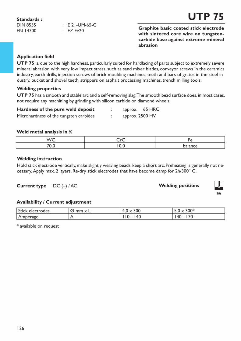
126
Graphite basic coated stick electrode with sintered core wire on tungsten-carbide base against extreme mineralabrasion
UTP 75
Welding instructionHold stick electrode vertically, make slightly weaving beads, keep a short arc. Preheating is generally not ne-cessary. Apply max. 2 layers. Re-dry stick electrodes that have become damp for 2h/300° C.
* available on request
Application fieldUTP 75 is, due to the high hardness, particularly suited for hardfacing of parts subject to extremely severemineral abrasion with very low impact stress, such as sand mixer blades, conveyor screws in the ceramicsindustry, earth drills, injection screws of brick moulding machines, teeth and bars of grates in the steel in-dustry, bucket and shovel teeth, strippers on asphalt processing machines, trench milling tools.Welding propertiesUTP 75 has a smooth and stable arc and a self-removing slag. The smooth bead surface does, in most cases,not require any machining by grinding with silicon carbide or diamond wheels.Hardness of the pure weld deposit : approx. 65 HRCMicrohardness of the tungsten carbides : approx. 2500 HV
Weld metal analysis in %WC70,0
CrC10,0
Febalance
Availability / Current adjustmentStick electrodesAmperage
Ø mm x LA
4,0 x 300110 – 140
5,0 x 300*140 – 170
Current type DC (–) / AC
Standards :DIN 8555 : E 21-UM-65-GEN 14700 : EZ Fe20
Welding positions PA
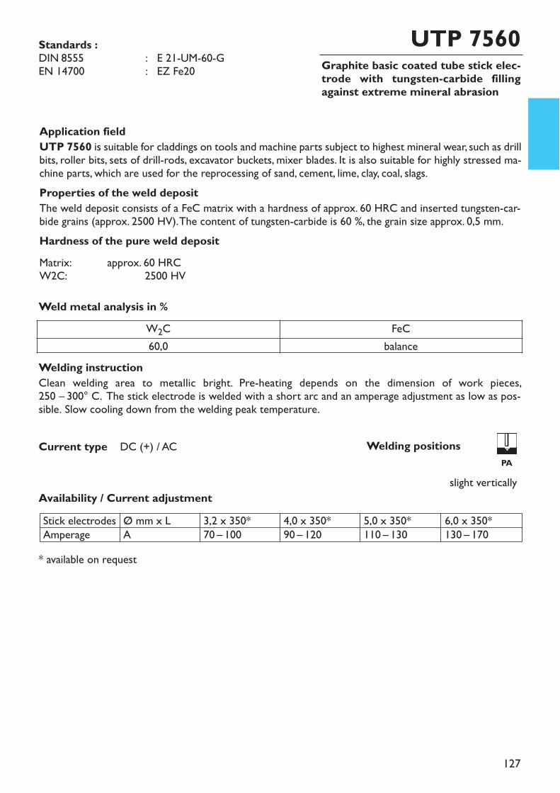
127
Graphite basic coated tube stick elec-trode with tungsten-carbide fillingagainst extreme mineral abrasion
UTP 7560
Availability / Current adjustment
Application fieldUTP 7560 is suitable for claddings on tools and machine parts subject to highest mineral wear, such as drillbits, roller bits, sets of drill-rods, excavator buckets, mixer blades. It is also suitable for highly stressed ma-chine parts, which are used for the reprocessing of sand, cement, lime, clay, coal, slags.Properties of the weld depositThe weld deposit consists of a FeC matrix with a hardness of approx. 60 HRC and inserted tungsten-car-bide grains (approx. 2500 HV). The content of tungsten-carbide is 60 %, the grain size approx. 0,5 mm.Hardness of the pure weld depositMatrix: approx. 60 HRCW2C: 2500 HV
* available on request
Stick electrodesAmperage
Ø mm x LA
3,2 x 350*70 – 100
4,0 x 350*90 – 120
5,0 x 350*110 – 130
6,0 x 350*130 – 170
Current type DC (+) / AC
slight vertically
Welding instruction Clean welding area to metallic bright. Pre-heating depends on the dimension of work pieces, 250 – 300° C. The stick electrode is welded with a short arc and an amperage adjustment as low as pos-sible. Slow cooling down from the welding peak temperature.
W2C FeC60,0 balance
Weld metal analysis in %
Standards :DIN 8555 : E 21-UM-60-GEN 14700 : EZ Fe20
Welding positionsPA
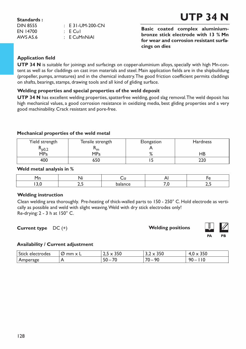
128
Basic coated complex aluminium-bronze stick electrode with 13 % Mnfor wear and corrosion resistant surfa-cings on dies
UTP 34 N
Welding instructionClean welding area thoroughly. Pre-heating of thick-walled parts to 150 - 250° C. Hold electrode as verti-cally as possible and weld with slight weaving. Weld with dry stick electrodes only!Re-drying: 2 - 3 h at 150° C.
Application fieldUTP 34 N is suitable for joinings and surfacings on copper-aluminium alloys, specially with high Mn-con-tent as well as for claddings on cast iron materials and steel. Main application fields are in the shipbuildung(propeller, pumps, armatures) and in the chemical industry. The good friction coefficient permits claddingson shafts, bearings, stamps, drawing tools and all kind of gliding surface.Welding properties and special properties of the weld depositUTP 34 N has excellent welding properties, spatterfree welding, good slag removal. The weld deposit hashigh mechanical values, a good corrosion resistance in oxidizing media, best gliding properties and a verygood machinability. Crack resistant and pore-free.
Weld metal analysis in %
Availability / Current adjustment
Current type DC (+)
Tensile strengthRmMPa650
Yield strengthRp0,2MPa400
ElongationA%15
HardnessHB220
Mechanical properties of the weld metal
Standards :DIN 8555 : E 31-UM-200-CNEN 14700 : E Cu1AWS A5.6 : E CuMnNiAl
Mn13,0
Ni2,5
Cubalance
Al7,0
Fe2,5
Stick electrodesAmperage
Ø mm x LA
2,5 x 35050 – 70
3,2 x 35070 – 90
4,0 x 35090 – 110
Welding positionsPA PB
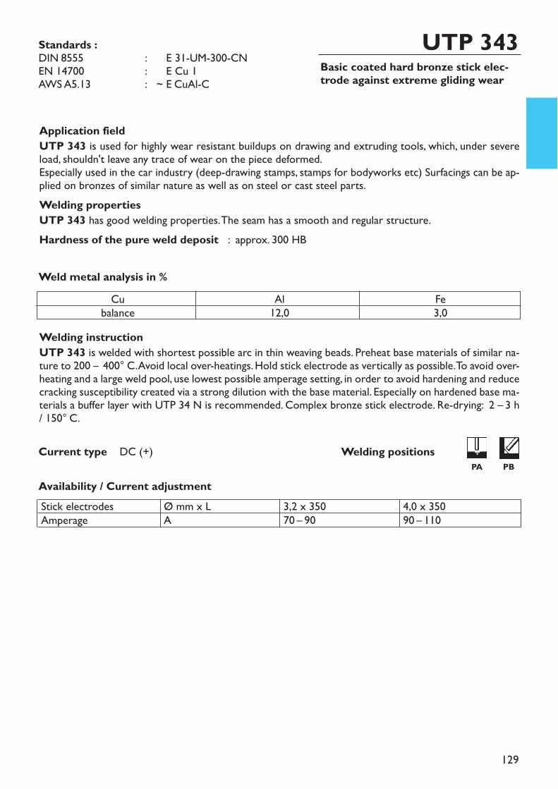
129
Basic coated hard bronze stick elec-trode against extreme gliding wear
UTP 343
Welding instructionUTP 343 is welded with shortest possible arc in thin weaving beads. Preheat base materials of similar na-ture to 200 – 400° C. Avoid local over-heatings. Hold stick electrode as vertically as possible. To avoid over-heating and a large weld pool, use lowest possible amperage setting, in order to avoid hardening and reducecracking susceptibility created via a strong dilution with the base material. Especially on hardened base ma-terials a buffer layer with UTP 34 N is recommended. Complex bronze stick electrode. Re-drying: 2 – 3 h/ 150° C.
Application fieldUTP 343 is used for highly wear resistant buildups on drawing and extruding tools, which, under severeload, shouldn't leave any trace of wear on the piece deformed.Especially used in the car industry (deep-drawing stamps, stamps for bodyworks etc) Surfacings can be ap-plied on bronzes of similar nature as well as on steel or cast steel parts.Welding propertiesUTP 343 has good welding properties. The seam has a smooth and regular structure.Hardness of the pure weld deposit : approx. 300 HB
Weld metal analysis in %
Availability / Current adjustment
Current type DC (+)
Standards :DIN 8555 : ~ E 31-UM-300-CNEN 14700 : ~ E Cu 1AWS A5.13 : ~ E CuAl-C
Cubalance
Al12,0
Fe3,0
Stick electrodesAmperage
Ø mm x LA
3,2 x 35070 – 90
4,0 x 35090 – 110
Welding positionsPA PB
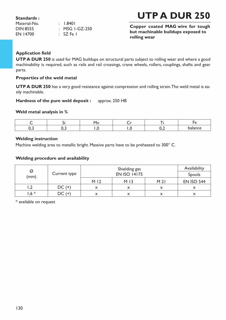
130
Copper coated MAG wire for toughbut machinable buildups exposed torolling wear
Welding instructionMachine welding area to metallic bright. Massive parts have to be preheated to 300° C.
Application fieldUTP A DUR 250 is used for MAG buildups on structural parts subject to rolling wear and where a goodmachinability is required, such as rails and rail crossings, crane wheels, rollers, couplings, shafts and gearparts.Properties of the weld metalUTP A DUR 250 has a very good resistance against compression and rolling strain. The weld metal is ea-sily machinable.Hardness of the pure weld deposit : approx. 250 HBWeld metal analysis in %
UTP A DUR 250
C0,3
Si0,3
Mn1,0
Cr1,0
Ti0,2
Febalance
Ø(mm) Current type Shielding gas
EN ISO 14175AvailabilitySpools
M 12 M 13 M 21 EN ISO 5441,2 DC (+) x x x x1,6 * DC (+) x x x x
Welding procedure and availability
* available on request
Standards :Material-No. : 1.8401DIN 8555 : MSG 1-GZ-250EN 14700 : SZ Fe 1
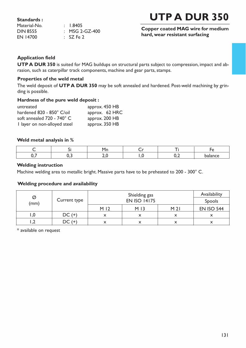
131
Copper coated MAG wire for mediumhard, wear resistant surfacing
Welding instructionMachine welding area to metallic bright. Massive parts have to be preheated to 200 - 300° C.
Application fieldUTP A DUR 350 is suited for MAG buildups on structural parts subject to compression, impact and ab-rasion, such as caterpillar track components, machine and gear parts, stamps. Properties of the weld metalThe weld deposit of UTP A DUR 350 may be soft annealed and hardened. Post-weld machining by grin-ding is possible.Hardness of the pure weld deposit :untreated approx. 450 HBhardened 820 - 850° C/oil approx. 62 HRCsoft annealed 720 - 740° C approx. 200 HB1 layer on non-alloyed steel approx. 350 HB
Weld metal analysis in %
UTP A DUR 350
* available on request
C0,7
Si0,3
Mn2,0
Cr1,0
Ti0,2
Febalance
Welding procedure and availability
Ø(mm) Current type Shielding gas
EN ISO 14175AvailabilitySpools
M 12 M 13 M 21 EN ISO 5441,0 DC (+) x x x x1,2 DC (+) x x x x
Standards :Material-No. : 1.8405DIN 8555 : MSG 2-GZ-400EN 14700 : SZ Fe 2
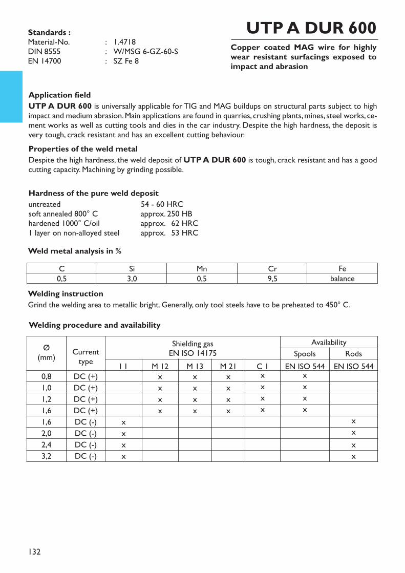
132
Copper coated MAG wire for highlywear resistant surfacings exposed toimpact and abrasion
Welding instructionGrind the welding area to metallic bright. Generally, only tool steels have to be preheated to 450° C.
Application fieldUTP A DUR 600 is universally applicable for TIG and MAG buildups on structural parts subject to highimpact and medium abrasion. Main applications are found in quarries, crushing plants, mines, steel works, ce-ment works as well as cutting tools and dies in the car industry. Despite the high hardness, the deposit isvery tough, crack resistant and has an excellent cutting behaviour. Properties of the weld metalDespite the high hardness, the weld deposit of UTP A DUR 600 is tough, crack resistant and has a goodcutting capacity. Machining by grinding possible.
Hardness of the pure weld deposituntreated 54 - 60 HRCsoft annealed 800° C approx. 250 HBhardened 1000° C/oil approx. 62 HRC1 layer on non-alloyed steel approx. 53 HRCWeld metal analysis in %
UTP A DUR 600
C0,5
Si3,0
Mn0,5
Cr9,5
Febalance
Welding procedure and availability
Ø(mm) Current
typeShielding gasEN ISO 14175
AvailabilitySpools Rods
I 1 M 12 M 13 M 21 C 1 EN ISO 544 EN ISO 5440,8 DC (+) x x x x x1,0 DC (+) x x x x x1,2 DC (+) x x x x x1,6 DC (+) x x x x x1,6 DC (-) x x2,0 DC (-) x x2,4 DC (-) x x3,2 DC (-) x x
Standards :Material-No. : 1.4718DIN 8555 : W/MSG 6-GZ-60-SEN 14700 : SZ Fe 8
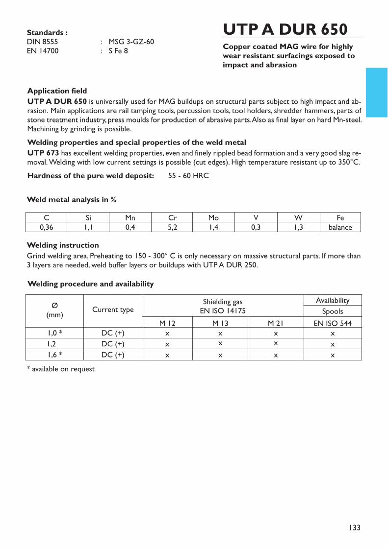
133
Copper coated MAG wire for highlywear resistant surfacings exposed toimpact and abrasion
Welding instructionGrind welding area. Preheating to 150 - 300° C is only necessary on massive structural parts. If more than3 layers are needed, weld buffer layers or buildups with UTP A DUR 250.
Application fieldUTP A DUR 650 is universally used for MAG buildups on structural parts subject to high impact and ab-rasion. Main applications are rail tamping tools, percussion tools, tool holders, shredder hammers, parts ofstone treatment industry, press moulds for production of abrasive parts. Also as final layer on hard Mn-steel.Machining by grinding is possible.Welding properties and special properties of the weld metalUTP 673 has excellent welding properties, even and finely rippled bead formation and a very good slag re-moval. Welding with low current settings is possible (cut edges). High temperature resistant up to 350°C.Hardness of the pure weld deposit: 55 - 60 HRC
Weld metal analysis in %
UTP A DUR 650
* available on request
C0,36
Si1,1
Mn0,4
Cr5,2
Mo1,4
V0,3
W1,3
Febalance
Welding procedure and availability
Ø(mm) Current type Shielding gas
EN ISO 14175AvailabilitySpools
M 12 M 13 M 21 EN ISO 5441,0 * DC (+) x x x x1,2 DC (+) x x x x1,6 * DC (+) x x x x
Standards :DIN 8555 : MSG 3-GZ-60EN 14700 : S Fe 8

134
Sintered TIG hard metal rod on tungsten carbide baseagainst extreme friction wear
Welding instructionClean welding area thoroughly. Generally no pre-heating, pre-heat massive parts to 150 – 200° C. Apply wel-ding rod in droplets with a crescent-shaped movement of the TIG-torch. Pay attention to a low dilution withthe base metal. Clad wihout interruption, if possible. Finishing by using diamond-grinding wheels or by was-hing.
* available on request
Standards :DIN 8555 : WSG 21-GS-60-G
Application fieldUTP A SUPER DUR W 80 Ni is suitable for highly wear resistant claddings on parts subject to extremefriction and grinding wear, particularly for barking blades, drawing heads, traction wheels, descaling rolls,mixer blades, pressure worms, pressing nozzles, impeller bars, fly cutters for tunnel construction and coalmining, guide jaws and - plates.Welding properties and special properties of the weld metalThe weld deposit of UTP A SUPER DUR W 80 Ni consists of very hard tungsten carbides, distribu-ted in a Ferro-Nickel-Matrix. A very good resistance against abrasion strain is the high part of tungstencarbides.Hardness of the pure weld metal : 55 - 60 HRCMicrohardness of the tungsten carbides : approx. 2500 HVWeld metal analysis in %
UTP A SUPER DUR W 80 Ni
WC80,0
Ni10,0
Fe10,0
Welding procedure and availability
Ø(mm) Current type Shielding gas
EN ISO 14175Availability
RodsI 1 I 2 L (mm)
3,3 * DC (-) x 3004,0 * DC (-) x 300
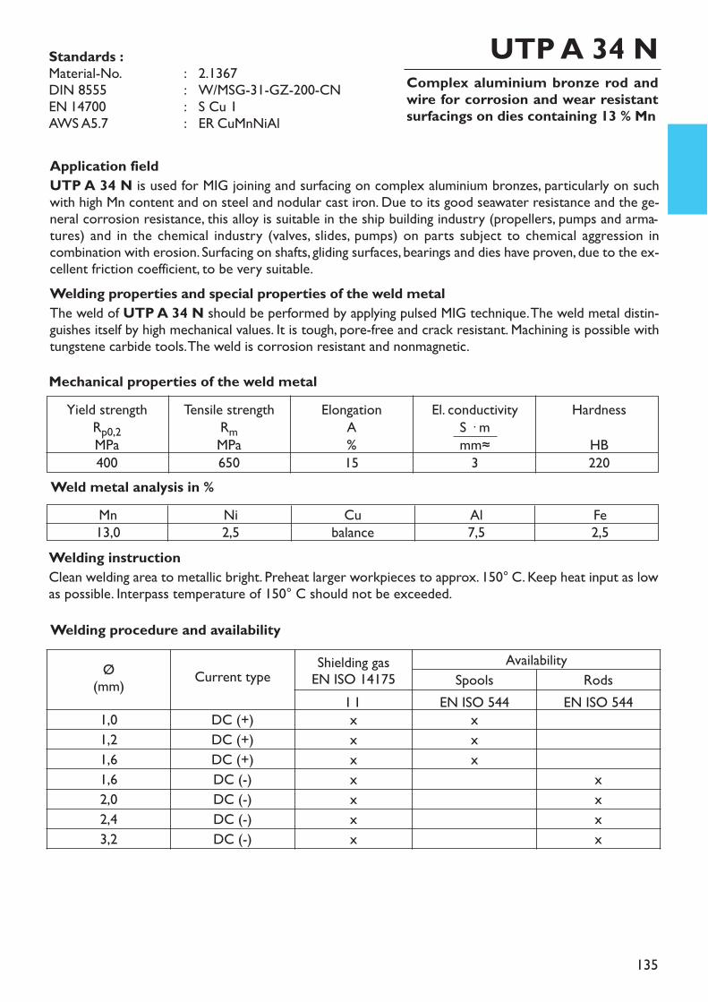
Tensile strengthRmMPa650
Yield strengthRp0,2MPa400
ElongationA%15
El. conductivityS � mmm≈3
HardnessHB220
Mechanical properties of the weld metal
135
Complex aluminium bronze rod andwire for corrosion and wear resistantsurfacings on dies containing 13 % Mn
Welding instructionClean welding area to metallic bright. Preheat larger workpieces to approx. 150° C. Keep heat input as lowas possible. Interpass temperature of 150° C should not be exceeded.
Application fieldUTP A 34 N is used for MIG joining and surfacing on complex aluminium bronzes, particularly on suchwith high Mn content and on steel and nodular cast iron. Due to its good seawater resistance and the ge-neral corrosion resistance, this alloy is suitable in the ship building industry (propellers, pumps and arma-tures) and in the chemical industry (valves, slides, pumps) on parts subject to chemical aggression incombination with erosion. Surfacing on shafts, gliding surfaces, bearings and dies have proven, due to the ex-cellent friction coefficient, to be very suitable.Welding properties and special properties of the weld metalThe weld of UTP A 34 N should be performed by applying pulsed MIG technique. The weld metal distin-guishes itself by high mechanical values. It is tough, pore-free and crack resistant. Machining is possible withtungstene carbide tools. The weld is corrosion resistant and nonmagnetic.
UTP A 34 N
Weld metal analysis in %Mn13,0
Ni2,5
Cubalance
Al7,5
Fe2,5
Standards :Material-No. : 2.1367DIN 8555 : W/MSG-31-GZ-200-CNEN 14700 : S Cu 1AWS A5.7 : ER CuMnNiAl
Welding procedure and availability
Ø(mm) Current type Shielding gas
EN ISO 14175Availability
Spools RodsI 1 EN ISO 544 EN ISO 544
1,0 DC (+) x x1,2 DC (+) x x1,6 DC (+) x x1,6 DC (-) x x2,0 DC (-) x x2,4 DC (-) x x3,2 DC (-) x x
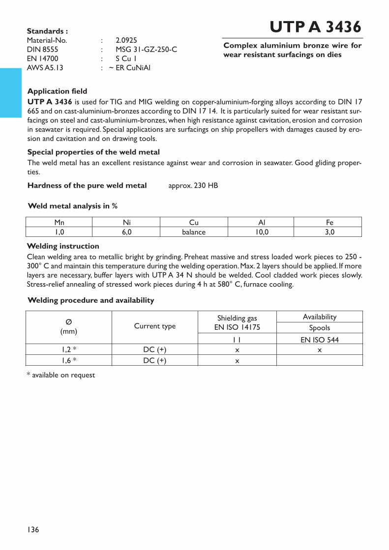
136
Complex aluminium bronze wire forwear resistant surfacings on dies
Welding instructionClean welding area to metallic bright by grinding. Preheat massive and stress loaded work pieces to 250 -300° C and maintain this temperature during the welding operation. Max. 2 layers should be applied. If morelayers are necessary, buffer layers with UTP A 34 N should be welded. Cool cladded work pieces slowly.Stress-relief annealing of stressed work pieces during 4 h at 580° C, furnace cooling.
* available on request
Application fieldUTP A 3436 is used for TIG and MIG welding on copper-aluminium-forging alloys according to DIN 17665 and on cast-aluminium-bronzes according to DIN 17 14. It is particularly suited for wear resistant sur-facings on steel and cast-aluminium-bronzes, when high resistance against cavitation, erosion and corrosionin seawater is required. Special applications are surfacings on ship propellers with damages caused by ero-sion and cavitation and on drawing tools.Special properties of the weld metalThe weld metal has an excellent resistance against wear and corrosion in seawater. Good gliding proper-ties.Hardness of the pure weld metal approx. 230 HB
UTP A 3436
Weld metal analysis in %Mn1,0
Ni6,0
Cubalance
Al10,0
Fe3,0
Standards :Material-No. : ~ 2.0925DIN 8555 : ~ MSG 31-GZ-250-CEN 14700 : ~ S Cu 1AWS A5.13 : ~ ER CuNiAl
Welding procedure and availability
Ø(mm) Current type Shielding gas
EN ISO 14175AvailabilitySpools
I 1 EN ISO 5441,2 * DC (+) x x1,6 * DC (+) x
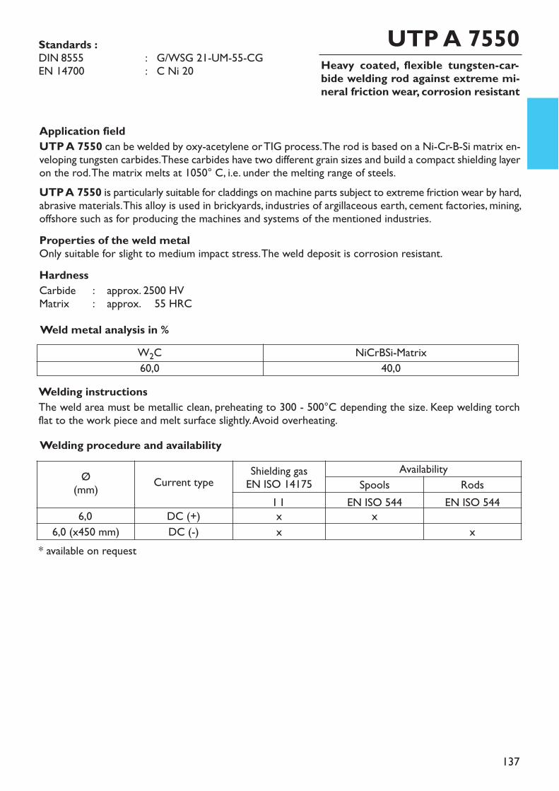
137
Heavy coated, flexible tungsten-car-bide welding rod against extreme mi-neral friction wear, corrosion resistant
* available on request
Application fieldUTP A 7550 can be welded by oxy-acetylene or TIG process. The rod is based on a Ni-Cr-B-Si matrix en-veloping tungsten carbides. These carbides have two different grain sizes and build a compact shielding layeron the rod. The matrix melts at 1050° C, i.e. under the melting range of steels. UTP A 7550 is particularly suitable for claddings on machine parts subject to extreme friction wear by hard,abrasive materials. This alloy is used in brickyards, industries of argillaceous earth, cement factories, mining,offshore such as for producing the machines and systems of the mentioned industries.Properties of the weld metalOnly suitable for slight to medium impact stress. The weld deposit is corrosion resistant.HardnessCarbide : approx. 2500 HVMatrix : approx. 2555 HRCWeld metal analysis in %
UTP A 7550Standards :DIN 8555 : G/WSG 21-UM-55-CGEN 14700 : C Ni 20
W2C60,0
NiCrBSi-Matrix40,0
Welding instructionsThe weld area must be metallic clean, preheating to 300 - 500°C depending the size. Keep welding torchflat to the work piece and melt surface slightly. Avoid overheating.Welding procedure and availability
Ø(mm) Current type Shielding gas
EN ISO 14175Availability
Spools RodsI 1 EN ISO 544 EN ISO 544
6,0 DC (+) x x6,0 (x450 mm) DC (-) x x
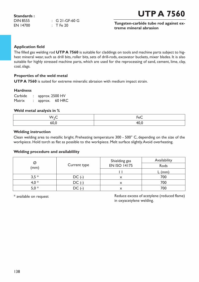
138
Tungsten-carbide tube rod against ex-treme mineral abrasion
Application fieldThe filled gas welding rod UTP A 7560 is suitable for claddings on tools and machine parts subject to hig-hest mineral wear, such as drill bits, roller bits, sets of drill-rods, excavator buckets, mixer blades. It is alsosuitable for highly stressed machine parts, which are used for the reprocessing of sand, cement, lime, clay,coal, slags.Properties of the weld metalUTP A 7560 is suited for extreme mineralic abrasion with medium impact strain.HardnessCarbide : approx. 2500 HVMatrix : approx. 2560 HRC
* available on request
UTP A 7560
Weld metal analysis in %W2C60,0
FeC40,0
Reduce excess of acetylene (reduced flame)in oxyacetylene welding.
Welding instruction Clean welding area to metallic bright. Preheating temperature 300 - 500° C, depending on the size of theworkpiece. Hold torch as flat as possible to the workpiece. Melt surface slightly. Avoid overheating.Welding procedure and availablility
Ø(mm) Current type Shielding gas
EN ISO 14175Availability
RodsI 1 L (mm)
3,5 * DC (-) x 7004,0 * DC (-) x 7005,0 * DC (-) x 700
Standards :DIN 8555 : G 21-GF-60 GEN 14700 : T Fe 20
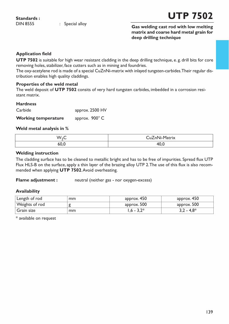
139
Gas welding cast rod with low meltingmatrix and coarse hard metal grain fordeep drilling technique
Application fieldUTP 7502 is suitable for high wear resistant cladding in the deep drilling technique, e. g. drill bits for coreremoving holes, stabilizer, face cutters such as in mining and foundries.The oxy-acetylene rod is made of a special CuZnNi-matrix with inlayed tungsten-carbides. Their regular dis-tribution enables high quality claddings.Properties of the weld metalThe weld deposit of UTP 7502 consits of very hard tungsten carbides, imbedded in a corrosion resi-stant matrix.HardnessCarbide approx. 2500 HVWorking temperature approx. 900° C
UTP 7502Standards :DIN 8555 : Special alloy
Welding instructionThe cladding surface has to be cleaned to metallic bright and has to be free of impurities. Spread flux UTPFlux HLS-B on the surface, apply a thin layer of the brazing alloy UTP 2. The use of this flux is also recom-mended when applying UTP 7502. Avoid overheating.
Length of rod mm approx. 450 approx. 450Weights of rod g approx. 500 approx. 500Grain size mm 1,6 - 3,2* 3,2 - 4,8*
AvailabilityFlame adjustment : neutral (neither gas - nor oxygen-excess)
W2C60,0
CuZnNi-Matrix40,0
Weld metal analysis in %
* available on request
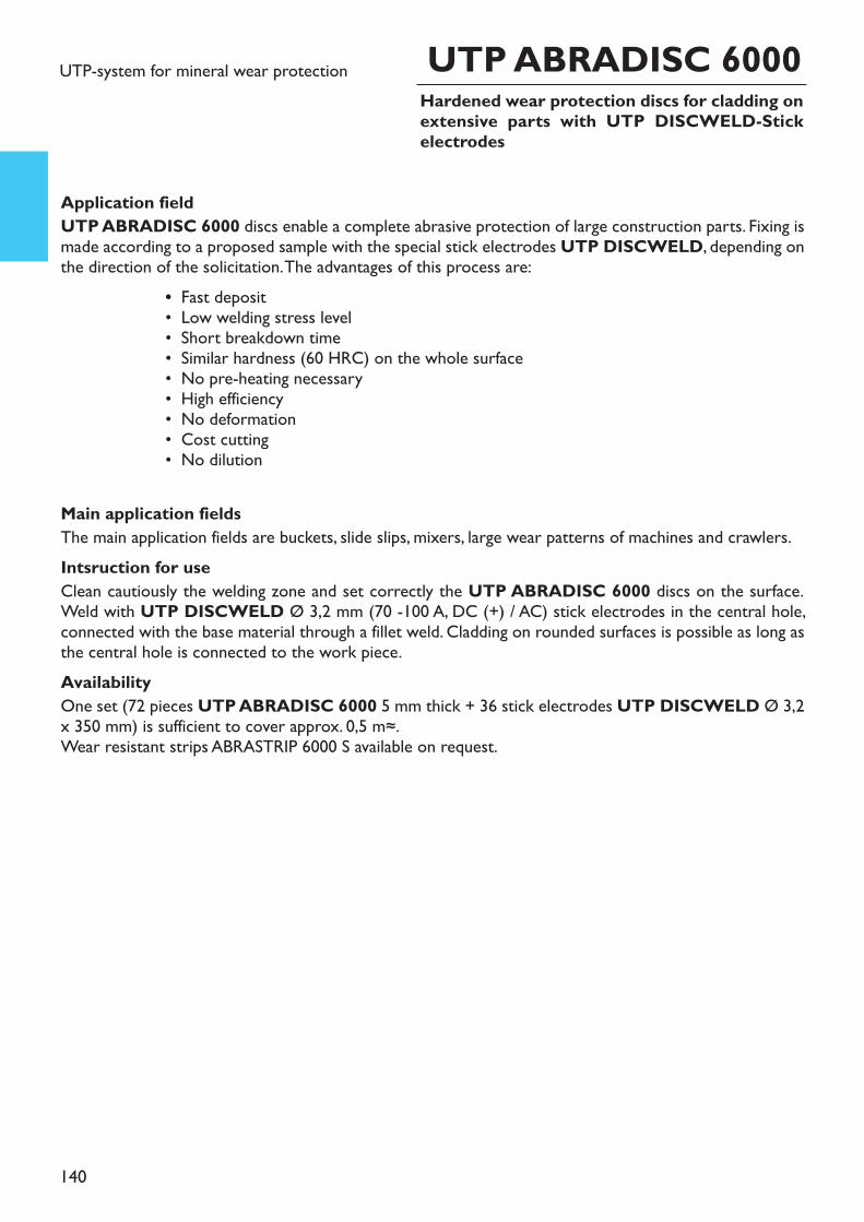
140
UTP ABRADISC 6000UTP-system for mineral wear protection
Application fieldUTP ABRADISC 6000 discs enable a complete abrasive protection of large construction parts. Fixing ismade according to a proposed sample with the special stick electrodes UTP DISCWELD, depending onthe direction of the solicitation. The advantages of this process are:
• Fast deposit• Low welding stress level• Short breakdown time• Similar hardness (60 HRC) on the whole surface• No pre-heating necessary• High efficiency• No deformation• Cost cutting• No dilution
Main application fieldsThe main application fields are buckets, slide slips, mixers, large wear patterns of machines and crawlers. Intsruction for useClean cautiously the welding zone and set correctly the UTP ABRADISC 6000 discs on the surface.Weld with UTP DISCWELD Ø 3,2 mm (70 -100 A, DC (+) / AC) stick electrodes in the central hole,connected with the base material through a fillet weld. Cladding on rounded surfaces is possible as long asthe central hole is connected to the work piece.AvailabilityOne set (72 pieces UTP ABRADISC 6000 5 mm thick + 36 stick electrodes UTP DISCWELD Ø 3,2x 350 mm) is sufficient to cover approx. 0,5 m≈. Wear resistant strips ABRASTRIP 6000 S available on request.
Hardened wear protection discs for cladding onextensive parts with UTP DISCWELD-Stickelectrodes
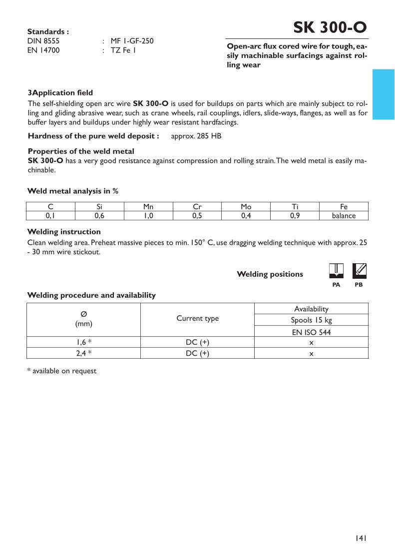
141
3Application fieldThe self-shielding open arc wire SK 300-O is used for buildups on parts which are mainly subject to rol-ling and gliding abrasive wear, such as crane wheels, rail couplings, idlers, slide-ways, flanges, as well as forbuffer layers and buildups under highly wear resistant hardfacings.Hardness of the pure weld deposit : approx. 285 HBProperties of the weld metalSK 300-O has a very good resistance against compression and rolling strain. The weld metal is easily ma-chinable.
Welding instructionClean welding area. Preheat massive pieces to min. 150° C, use dragging welding technique with approx. 25- 30 mm wire stickout.
Weld metal analysis in %
* available on request
Open-arc flux cored wire for tough, ea-sily machinable surfacings against rol-ling wear
SK 300-O
Welding procedure and availability
Standards :DIN 8555 : MF 1-GF-250EN 14700 : TZ Fe 1
Welding positionsPA PB
C Si Mn Cr Mo Ti Fe0,1 0,6 1,0 0,5 0,4 0,9 balance
Ø(mm) Current type
AvailabilitySpools 15 kgEN ISO 544
1,6 * DC (+) x2,4 * DC (+) x

142
Application fieldThe metal powder flux cored wire SK 250-G is suitable for surfacings on construction parts subject mainlyto rolling and gliding wear in combination with high compression and shock, such as jaw linkages, gearwheels,shafts, couplings. A further application field is buffer - and cushion layers on hard alloys. Easily machinable.Hardness of the pure weld metal : 225 HBProperties of the weld metalSK 250-G has a very good resistance against compression and rolling strain. The weld metal is easily ma-chinable.
* available on request
Welding instructionClean welding area to metallic bright. Preheat massive parts to min. 150° C. Use dragging or pushing wel-ding technique in spray arc with approx. 20 mm wire stickout.
Weld metal analysis in %
MAG flux cored wire for tough, easily machi-nable surfacings against rolling wear
SK 250-GStandards :DIN 8555 : MF 1-GF-250EN 14700 : TZ Fe 1
Welding procedure and availability
Welding positionsPA PB
C0,09
Si0,5
Mn1,2
Cr0,45
Febalance
Ø(mm) Current type Shielding gas
EN ISO 14175AvailabilitySpools
M 21 EN ISO 5441,2 DC (+) x x1,6 * DC (+) x x
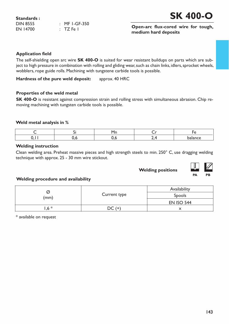
143
Open-arc flux-cored wire for tough,medium hard deposits
Application fieldThe self-shielding open arc wire SK 400-O is suited for wear resistant buildups on parts which are sub-ject to high pressure in combination with rolling and gliding wear, such as chain links, idlers, sprocket wheels,wobblers, rope guide rolls. Machining with tungstene carbide tools is possible.Hardness of the pure weld deposit: approx. 40 HRC
Properties of the weld metalSK 400-O is resistant against compression strain and rolling stress with simultaneous abrasion. Chip re-moving machining with tungsten carbide tools is possible.
Welding instructionClean welding area. Preheat massive pieces and high strength steels to min. 250° C, use dragging weldingtechnique with approx. 25 - 30 mm wire stickout.
Weld metal analysis in %
* available on request
Standards :DIN 8555 : MF 1-GF-350EN 14700 : TZ Fe 1
SK 400-O
Welding procedure and availability
143
Welding positionsPA PB
C0,11
Si0,6
Mn0,6
Cr2,4
Febalance
Ø(mm) Current type
AvailabilitySpools
EN ISO 5441,6 * DC (+) x

144
Application fieldThe metal powder flux cored wire SK 350-G is suitable for surfacings on construction parts subject to highshock in combination with rolling and gliding wear, such as carriage parts of crawler vehicles, sprocketwheels, rope pulleys, shafts, gearwheels, gliding metals parts. Easily machinable.Properties of the weld metalSK 350-G is resistant against compression strain and rolling stress with simultaneous abrasion. Chip re-moving machining with tungsten carbide tools is possible.
Hardness of the pure weld metal : 330 HB
Welding instructionClean welding area to metallic bright. Preheat massive construction parts and high strength steel to min. 250°C. Use dragging or pushing welding technique with approx. 20 mm wire stickout.
Weld metal analysis in %
MAG flux cored wire for tough, medium hardsurfacings
SK 350-GStandards :DIN 8555 : MF 1-GF-350EN 14700 : T Z Fe1
Welding procedure and availabilityWelding positions
PA PB
C0,22
Si0,4
Mn1,4
Cr1,45
Mo0,5
Febalance
Ø(mm) Current type Shielding gas
EN ISO 14175AvailabilitySpools
M 21 C 1 EN ISO 5441,2 DC (+) x x x1,6 DC (+) x x x
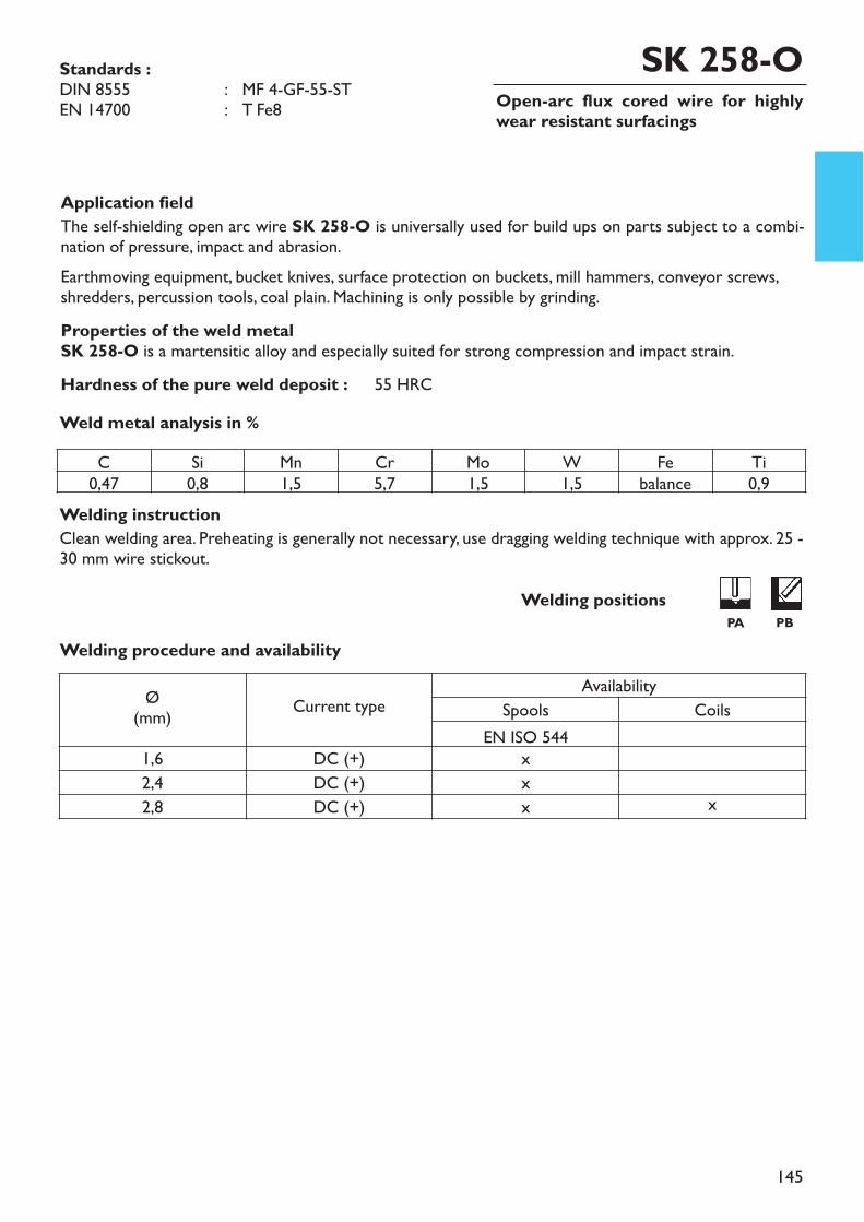
145
Open-arc flux cored wire for highlywear resistant surfacings
Application fieldThe self-shielding open arc wire SK 258-O is universally used for build ups on parts subject to a combi-nation of pressure, impact and abrasion.Earthmoving equipment, bucket knives, surface protection on buckets, mill hammers, conveyor screws,shredders, percussion tools, coal plain. Machining is only possible by grinding.Properties of the weld metalSK 258-O is a martensitic alloy and especially suited for strong compression and impact strain.Hardness of the pure weld deposit : 55 HRC
Welding instructionClean welding area. Preheating is generally not necessary, use dragging welding technique with approx. 25 -30 mm wire stickout.
Weld metal analysis in %
Welding procedure and availability
SK 258-OStandards :DIN 8555 : MF 4-GF-55-STEN 14700 : T Fe8
Welding positionsPA PB
C Si Mn Cr Mo W Fe Ti0,47 0,8 1,5 5,7 1,5 1,5 balance 0,9
Ø(mm) Current type
AvailabilitySpools Coils
EN ISO 5441,6 DC (+) x2,4 DC (+) x2,8 DC (+) x x
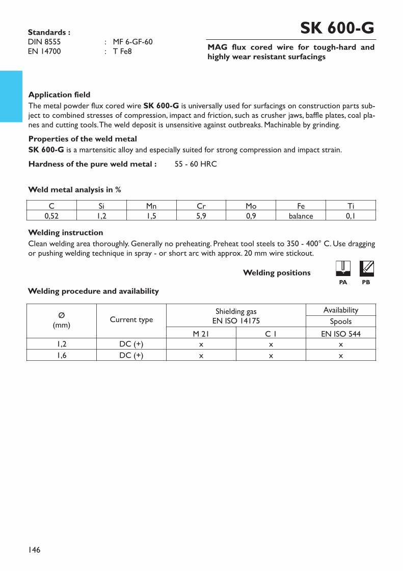
146
MAG flux cored wire for tough-hard andhighly wear resistant surfacings
Application fieldThe metal powder flux cored wire SK 600-G is universally used for surfacings on construction parts sub-ject to combined stresses of compression, impact and friction, such as crusher jaws, baffle plates, coal pla-nes and cutting tools. The weld deposit is unsensitive against outbreaks. Machinable by grinding.Properties of the weld metalSK 600-G is a martensitic alloy and especially suited for strong compression and impact strain.Hardness of the pure weld metal : 55 - 60 HRC
Welding instructionClean welding area thoroughly. Generally no preheating. Preheat tool steels to 350 - 400° C. Use draggingor pushing welding technique in spray - or short arc with approx. 20 mm wire stickout.
Weld metal analysis in %
SK 600-GStandards :DIN 8555 : MF 6-GF-60EN 14700 : T Fe8
Welding procedure and availabilityWelding positions
PA PB
C Si Mn Cr Mo Fe Ti0,52 1,2 1,5 5,9 0,9 balance 0,1
Ø(mm) Current type Shielding gas
EN ISO 14175AvailabilitySpools
M 21 C 1 EN ISO 5441,2 DC (+) x x x1,6 DC (+) x x x

147
MAG flux cored wire for tough-hard surfa-cings against impact and abrasion
Application fieldThe metal powder flux cored wire SK 650-G is used for buildups on parts subject to compression, impactand abrasion, such as cutting edges and working surfaces on cold and hot working tools, forging and trim-ming dies, axial and planing rolls, rotors and beaters for mineral and stone crushing, teeth and scraper bla-des of building machines, taper tools and shredder hammers. Properties of the weld metalMachining is possible by grinding or with tungstene carbide tools.Hardness of the pure weld metal: 58 HRC
Welding instructionClean welding area to metallic bright. Preheat hot - and cold working tools to 400° C, stress relief, if ne-cessary, at 550° C. Use dragging or pushing welding technique in spray - or short arc with approx. 20 mmwire stickout.
Weld metal analysis in %
SK 650-G
Welding procedure and availability
Standards :DIN 8555 : MF 10-GF-60-GPEN 14700 : T Fe8
Welding positionsPA PB
C0,45
Si0,6
Mn0,9
Cr5,5
Mo1,4
V1,0
W1,6
Febalance
* available on request
Ø(mm) Current type Shielding gas
EN ISO 14175AvailabilitySpools
M 21 C 1 EN ISO 5441,2 DC (+) x x x1,6 DC (+) x x x2,4 * DC (+) x x x

148
Open-arc TiC flux cored wire for wear re-sistant claddings against compression,impact and abrasion
Application fieldThe self-shielded (open-arc) flux cored wire SK 258 TiC-O is universally suitable for claddings on wearingparts subject to combined loads of impact and abrasion, such as breaking drums and hammer crushers,crushing parts, gravel pumps, conveyor screws, pressure drums for the cement industry, mixer parts, earth-work equipment. Machinable by grinding. Max applied thickness 10 - 15 mm in 3 - 4 layers.Properties of the weld metalThe weld deposit of SK 258 TiC-O is goog machinable by grinding and is consisting of a martensitic ma-trix with finely distributed Ti-carbides. (not suited for flame-cutting)Hardness of the pure weld metal: 58 HRC
Welding instructionClean welding area to metallic bright. Peheat massive parts and high performance steels to min. 250° C. Dueto a high preheating and working temperature the crack susceptibility of the weld deposit will be reduced.Use dragging welding technique with approx. 35 - 40 mm wire stickout.
Weld metal analysis in %
Welding procedure and availability
SK 258 TiC-OStandards :DIN 8555 : MF 6-GF-60-GPEN 14700 : T Z Fe8
Welding positionsPA PB
C1,8
Si0,2
Mn0,9
Cr6,1
Mo1,4
Ti5,5
Febalance
Ø(mm) Current type
AvailabilitySpools Coils Drums
EN ISO 5441,2 DC (+) x1,6 DC (+) x1,6 * DC (+) x2,4 DC (+) x2,4 * DC (+) x2,8 DC (+) x x2,8 * DC (+) x

149
Application fieldThe metal powder flux cored wire SK 258 TiC-G is universally suitable for claddings on wearing parts sub-ject to a combined loads of impact and abrasion, such as breaking drums and hammer crushers, crushingparts, gravel pumps, conveyor screws, pressure drums for the cement industry, mixer parts, earthworkequipment. Machinable by grinding. Max applied thick-ness 10 - 15 mm in 3 - 4 layers.Properties of the weld metalThe weld deposit of SK 258 TiC-G is goog machinable by grinding and is consisting of a martensitic ma-trix with finely distributed Ti-carbides. (not suited for flame-cutting)Hardness of the pure weld deposit : 59 HRC
Welding instructionClean welding area to metallic bright. Preheat massive construction parts and high strength steel to min. 250°C. Due to a high preheating and working temperature the crack susceptibility of the weld deposit will bereduced. Use pushing or dragging welding technique with spray arc and with approx. 20 mm wire stickout.
* available on request
Weld metal analysis in %
MAG TiC flux cored wire for wear resistant clad-dings against compression, impact and abrasion
SK 258 TiC-GStandards : DIN 8555 : MF 6-GF-60-GPEN 14700 : T Z Fe8
Welding procedure and availabilityWelding positions
PA PB
C1,6
Si0,3
Mn0,8
Cr5,6
Mo1,1
Ti5,8
Febalance
Ø(mm) Current type Shielding gas
EN ISO 14175Availability
Spools CoilsM 13 EN ISO 544
1,2 DC (+) x x1,6 DC (+) x x2,0 * DC (+) x x2,4 * DC (+) x x2,8 DC (+) x x
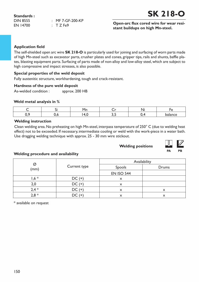
150
Open-arc flux cored wire for wear resi-stant buildups on high Mn-steel.
Application fieldThe self-shielded open arc wire SK 218-O is particularly used for joining and surfacing of worn parts madeof high Mn-steel such as excavator parts, crusher plates and cones, gripper tips, rails and shunts, baffle pla-tes, blasting equipment parts. Surfacing of parts made of non-alloy and low-alloy steel, which are subject tohigh compressive and impact stresses, is also possible.Special properties of the weld depositFully austenitic structure, workhardening, tough and crack-resistant.Hardness of the pure weld depositAs-welded condition : approx. 200 HB
Welding instructionClean welding area. No preheating on high Mn-steel, interpass temperature of 250° C (due to welding heateffect) not to be exceeded. If necessary, intermediate cooling or weld with the work-piece in a water bath.Use dragging welding technique with approx. 25 - 30 mm wire stickout.
* available on request
Weld metal analysis in %
Welding procedure and availability
Ø(mm) Current type
AvailabilitySpools Drums
EN ISO 5441,6 * DC (+) x2,0 DC (+) x2,4 * DC (+) x x2,8 * DC (+) x x
SK 218-OStandards :DIN 8555 : MF 7-GF-200-KPEN 14700 : T Z Fe9
Welding positionsPA PB
C0,9
Si0,6
Mn14,0
Cr3,5
Ni0,4
Febalance
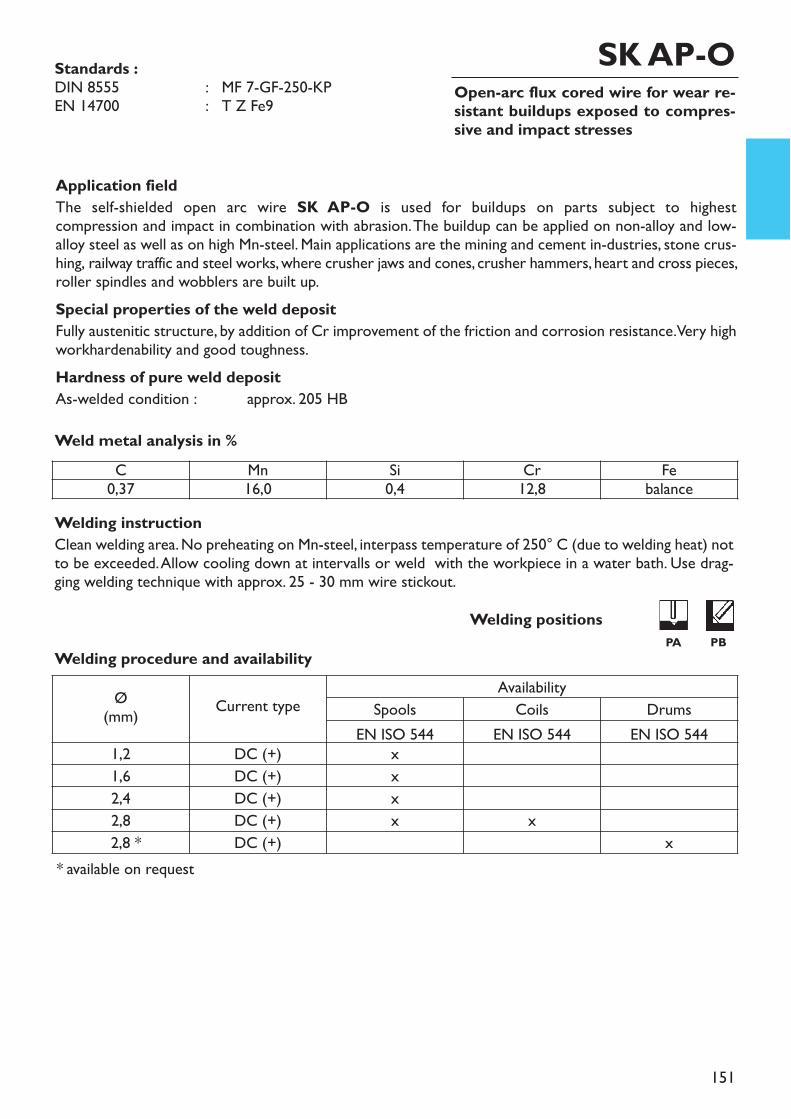
151
Open-arc flux cored wire for wear re-sistant buildups exposed to compres-sive and impact stresses
Application fieldThe self-shielded open arc wire SK AP-O is used for buildups on parts subject to highest compression and impact in combination with abrasion. The buildup can be applied on non-alloy and low-alloy steel as well as on high Mn-steel. Main applications are the mining and cement in-dustries, stone crus-hing, railway traffic and steel works, where crusher jaws and cones, crusher hammers, heart and cross pieces,roller spindles and wobblers are built up.Special properties of the weld depositFully austenitic structure, by addition of Cr improvement of the friction and corrosion resistance. Very highworkhardenability and good toughness.Hardness of pure weld depositAs-welded condition : approx. 205 HB
Welding instructionClean welding area. No preheating on Mn-steel, interpass temperature of 250° C (due to welding heat) notto be exceeded. Allow cooling down at intervalls or weld with the workpiece in a water bath. Use drag-ging welding technique with approx. 25 - 30 mm wire stickout.
* available on request
Weld metal analysis in %
Standards :DIN 8555 : MF 7-GF-250-KPEN 14700 : T Z Fe9
SK AP-O
Welding procedure and availabilityWelding positions
PA PB
Ø(mm) Current type
AvailabilitySpools Coils Drums
EN ISO 544 EN ISO 544 EN ISO 5441,2 DC (+) x1,6 DC (+) x2,4 DC (+) x2,8 DC (+) x x2,8 * DC (+) x
C Mn Si Cr Fe0,37 16,0 0,4 12,8 balance
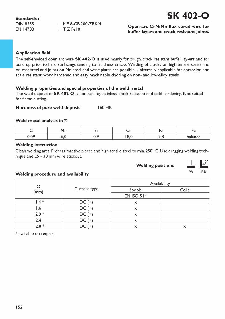
152
Open-arc CrNiMn flux cored wire forbuffer layers and crack resistant joints.
Application fieldThe self-shielded open arc wire SK 402-O is used mainly for tough, crack resistant buffer lay-ers and forbuild up prior to hard surfacings tending to hardness cracks. Welding of cracks on high tensile steels andon cast steel and joints on Mn-steel and wear plates are possible. Universally applicable for corrosion andscale resistant, work hardened and easy machinable cladding on non- and low-alloy steels.
Welding properties and special properties of the weld metalThe weld deposit of SK 402-O is non-scaling, stainless, crack resistant and cold hardening. Not suitedfor flame cutting.Hardness of pure weld deposit 160 HB
Welding instructionClean welding area. Preheat massive pieces and high tensile steel to min. 250° C. Use dragging welding tech-nique and 25 - 30 mm wire stickout.
Weld metal analysis in %
SK 402-OStandards :DIN 8555 : MF 8-GF-200-ZRKNEN 14700 : T Z Fe10
Welding procedure and availability
* available on request
Welding positionsPA PB
C Mn Si Cr Ni Fe0,09 6,0 0,9 18,0 7,8 balance
Ø(mm) Current type
AvailabilitySpools Coils
EN ISO 5441,4 * DC (+) x1,6 DC (+) x2,0 * DC (+) x2,4 DC (+) x2,8 * DC (+) x x
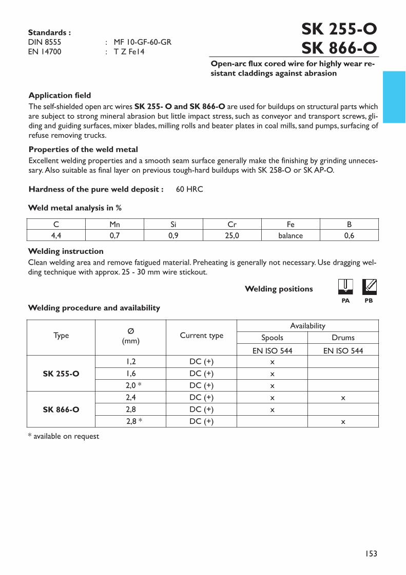
153
Open-arc flux cored wire for highly wear re-sistant claddings against abrasion
Application fieldThe self-shielded open arc wires SK 255- O and SK 866-O are used for buildups on structural parts whichare subject to strong mineral abrasion but little impact stress, such as conveyor and transport screws, gli-ding and guiding surfaces, mixer blades, milling rolls and beater plates in coal mills, sand pumps, surfacing ofrefuse removing trucks. Properties of the weld metalExcellent welding properties and a smooth seam surface generally make the finishing by grinding unneces-sary. Also suitable as final layer on previous tough-hard buildups with SK 258-O or SK AP-O.Hardness of the pure weld deposit : 60 HRC
Welding instructionClean welding area and remove fatigued material. Preheating is generally not necessary. Use dragging wel-ding technique with approx. 25 - 30 mm wire stickout.
Weld metal analysis in %
* available on request
Standards :DIN 8555 : MF 10-GF-60-GREN 14700 : T Z Fe14
Welding procedure and availabilityWelding positions
PA PB
SK 255-OSK 866-O
C Mn Si Cr Fe B4,4 0,7 0,9 25,0 balance 0,6
Type Ø(mm) Current type
AvailabilitySpools Drums
EN ISO 544 EN ISO 544
SK 255-O1,2 DC (+) x1,6 DC (+) x2,0 * DC (+) x
SK 866-O2,4 DC (+) x x2,8 DC (+) x2,8 * DC (+) x
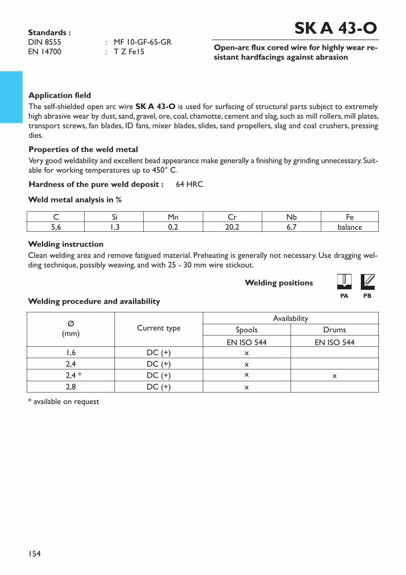
154
Open-arc flux cored wire for highly wear re-sistant hardfacings against abrasion
Application fieldThe self-shielded open arc wire SK A 43-O is used for surfacing of structural parts subject to extremelyhigh abrasive wear by dust, sand, gravel, ore, coal, chamotte, cement and slag, such as mill rollers, mill plates,transport screws, fan blades, ID fans, mixer blades, slides, sand propellers, slag and coal crushers, pressingdies. Properties of the weld metalVery good weldability and excellent bead appearance make generally a finishing by grinding unnecessary. Suit-able for working temperatures up to 450° C.Hardness of the pure weld deposit : 64 HRC
Welding instructionClean welding area and remove fatigued material. Preheating is generally not necessary. Use dragging wel-ding technique, possibly weaving, and with 25 - 30 mm wire stickout.
* available on request
Weld metal analysis in %
Standards :DIN 8555 : MF 10-GF-65-GREN 14700 : T Z Fe15
SK A 43-O
Welding procedure and availabilityWelding positions
PA PB
C5,6
Si1,3
Mn0,2
Cr20,2
Nb6,7
Febalance
Ø(mm) Current type
AvailabilitySpools Drums
EN ISO 544 EN ISO 5441,6 DC (+) x2,4 DC (+) x2,4 * DC (+) x x2,8 DC (+) x
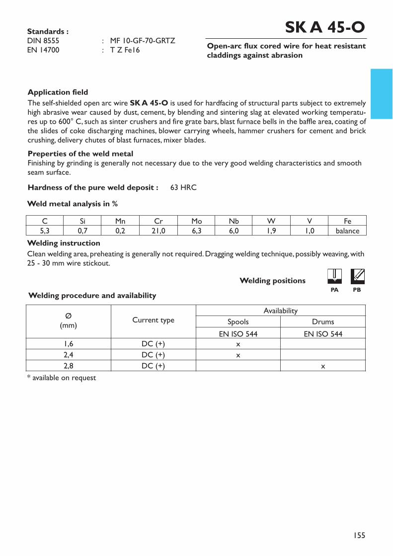
155
Open-arc flux cored wire for heat resistantcladdings against abrasion
Application fieldThe self-shielded open arc wire SK A 45-O is used for hardfacing of structural parts subject to extremelyhigh abrasive wear caused by dust, cement, by blending and sintering slag at elevated working temperatu-res up to 600° C, such as sinter crushers and fire grate bars, blast furnace bells in the baffle area, coating ofthe slides of coke discharging machines, blower carrying wheels, hammer crushers for cement and brickcrushing, delivery chutes of blast furnaces, mixer blades.Preperties of the weld metalFinishing by grinding is generally not necessary due to the very good welding characteristics and smoothseam surface.Hardness of the pure weld deposit : 63 HRC
Welding instructionClean welding area, preheating is generally not required. Dragging welding technique, possibly weaving, with25 - 30 mm wire stickout.
Weld metal analysis in %
Standards :DIN 8555 : MF 10-GF-70-GRTZEN 14700 : T Z Fe16
SK A 45-O
Welding procedure and availability
* available on request
Welding positionsPA PB
C5,3
Si0,7
Mn0,2
Cr21,0
Mo6,3
Nb6,0
W1,9
V1,0
Febalance
Ø(mm) Current type
AvailabilitySpools Drums
EN ISO 544 EN ISO 5441,6 DC (+) x2,4 DC (+) x2,8 DC (+) x
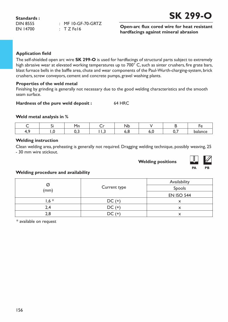
156
Open-arc flux cored wire for heat resistanthardfacings against mineral abrasion
Application fieldThe self-shielded open arc wire SK 299-O is used for hardfacings of structural parts subject to extremelyhigh abrasive wear at elevated working temperatures up to 700° C, such as sinter crushers, fire grate bars,blast furnace bells in the baffle area, chute and wear components of the Paul-Wurth-charging-system, brickcrushers, screw conveyors, cement and concrete pumps, gravel washing plants. Properties of the weld metalFinishing by grinding is generally not necessary due to the good welding characteristics and the smoothseam surface.Hardness of the pure weld deposit : 64 HRC
Welding instructionClean welding area, preheating is generally not required. Dragging welding technique, possibly weaving, 25- 30 mm wire stickout.
* available on request
Weld metal analysis in %
Standards :DIN 8555 : MF 10-GF-70-GRTZEN 14700 : T Z Fe16
SK 299-O
Welding procedure and availabilityWelding positions
PA PB
C4,9
Si1,0
Mn0,3
Cr11,3
Nb6,8
V6,0
B0,7
Febalance
Ø(mm) Current type
AvailabilitySpools
EN ISO 5441,6 * DC (+) x2,4 DC (+) x2,8 DC (+) x

157
Copper coated SAW wire for machinable sur-facings and filler layers
UTP UP DUR 250UTP UP FX DUR 250
Application fieldThe combination of wire and flux UTP UP DUR 250 / UTP UP FX DUR 250 is used for submergedarc welding on construction parts, where resistance against rolling wear and a good machinability is requi-red, such as surfacings on rail crossings, couplings, wobbler drives, crane wheels, shafts and gear parts.Hardness of the pure weld deposit : approx. 250 HB
Welding instructionClean welding area to metallic bright. Preheat massive parts to 150° C, cooling down slowly.
Wire analysis in %
Standards :Material-No. : 1.8401DIN 8555 : UP 1-GZ-250EN 14700 : SZ Fe1
C0,3
Si0,4
Mn1,0
Cr1,0
Ti0,2
Al0,1
Febalance
Welding procedure and availabilityØ
(mm)Welding data Availability
I (A) U (V) V (cm/min) Wire FluxEN ISO 544
3,0 * 400 - 500 28 - 30 30 - 50 B 450 25 kg4,0 * 500 - 600 28 - 30 30 - 50 B 450 25 kg
* available on request
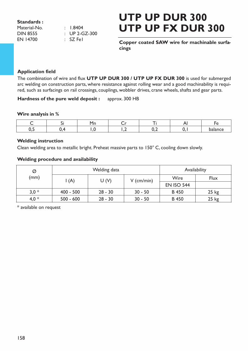
158
Copper coated SAW wire for machinable surfa-cings
UTP UP DUR 300UTP UP FX DUR 300
Application fieldThe combination of wire and flux UTP UP DUR 300 / UTP UP FX DUR 300 is used for submergedarc welding on construction parts, where resistance against rolling wear and a good machinability is requi-red, such as surfacings on rail crossings, couplings, wobbler drives, crane wheels, shafts and gear parts.Hardness of the pure weld deposit : approx. 300 HB
Welding instructionClean welding area to metallic bright. Preheat massive parts to 150° C, cooling down slowly.
Wire analysis in %
Standards :Material-No. : 1.8404DIN 8555 : UP 2-GZ-300EN 14700 : SZ Fe1
C0,5
Si0,4
Mn1,0
Cr1,2
Ti0,2
Al0,1
Febalance
Welding procedure and availabilityØ
(mm)Welding data Availability
I (A) U (V) V (cm/min) Wire FluxEN ISO 544
3,0 * 400 - 500 28 - 30 30 - 50 B 450 25 kg4,0 * 500 - 600 28 - 30 30 - 50 B 450 25 kg
* available on request
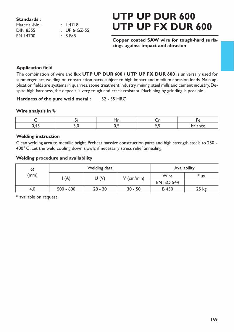
159
Copper coated SAW wire for tough-hard surfa-cings against impact and abrasion
UTP UP DUR 600UTP UP FX DUR 600
Application fieldThe combination of wire and flux UTP UP DUR 600 / UTP UP FX DUR 600 is universally used forsubmerged arc welding on construction parts subject to high impact and medium abrasion loads. Main ap-plication fields are systems in quarries, stone treatment industry, mining, steel mills and cement industry. De-spite high hardness, the deposit is very tough and crack resistant. Machining by grinding is possible.Hardness of the pure weld metal : 52 - 55 HRC
Welding instructionClean welding area to metallic bright. Preheat massive construction parts and high strength steels to 250 -400° C. Let the weld cooling down slowly, if necessary stress relief annealing.
Wire analysis in %C
0,45Si3,0
Mn0,5
Cr9,5
Febalance
* available on request
Welding procedure and availabilityØ
(mm)Welding data Availability
I (A) U (V) V (cm/min) Wire FluxEN ISO 544
4,0 500 - 600 28 - 30 30 - 50 B 450 25 kg
Standards :Material-No.. : 1.4718DIN 8555 : UP 6-GZ-55EN 14700 : S Fe8
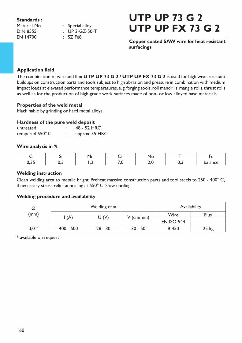
160
Copper coated SAW wire for heat resistantsurfacings
UTP UP 73 G 2UTP UP FX 73 G 2
Application fieldThe combination of wire and flux UTP UP 73 G 2 / UTP UP FX 73 G 2 is used for high wear resistantbuildups on construction parts and tools subject to high abrasion and pressure in combination with mediumimpact loads at elevated performance temperatures, e. g. forging tools, roll mandrills, mangle rolls, thrust rollsas well as for the production of high-grade work surfaces made of non- or low alloyed base materials. Properties of the weld metalMachinable by grinding or hard metal alloys.Hardness of the pure weld deposituntreated : 48 - 52 HRCtempered 550° C : approx. 55 HRC
Welding instructionClean welding area to metalic bright. Preheat massive construction parts and tool steels to 250 - 400° C,if necessary stress relief annealing at 550° C. Slow cooling.
Wire analysis in %
Standards :Material-No. : Special alloyDIN 8555 : UP 3-GZ-50-TEN 14700 : SZ Fe8
C0,35
Si0,3
Mn1,2
Cr7,0
Mo2,0
Ti0,3
Febalance
Welding procedure and availabilityØ
(mm)Welding data Availability
I (A) U (V) V (cm/min) Wire FluxEN ISO 544
3,0 * 400 - 500 28 - 30 30 - 50 B 450 25 kg* available on request
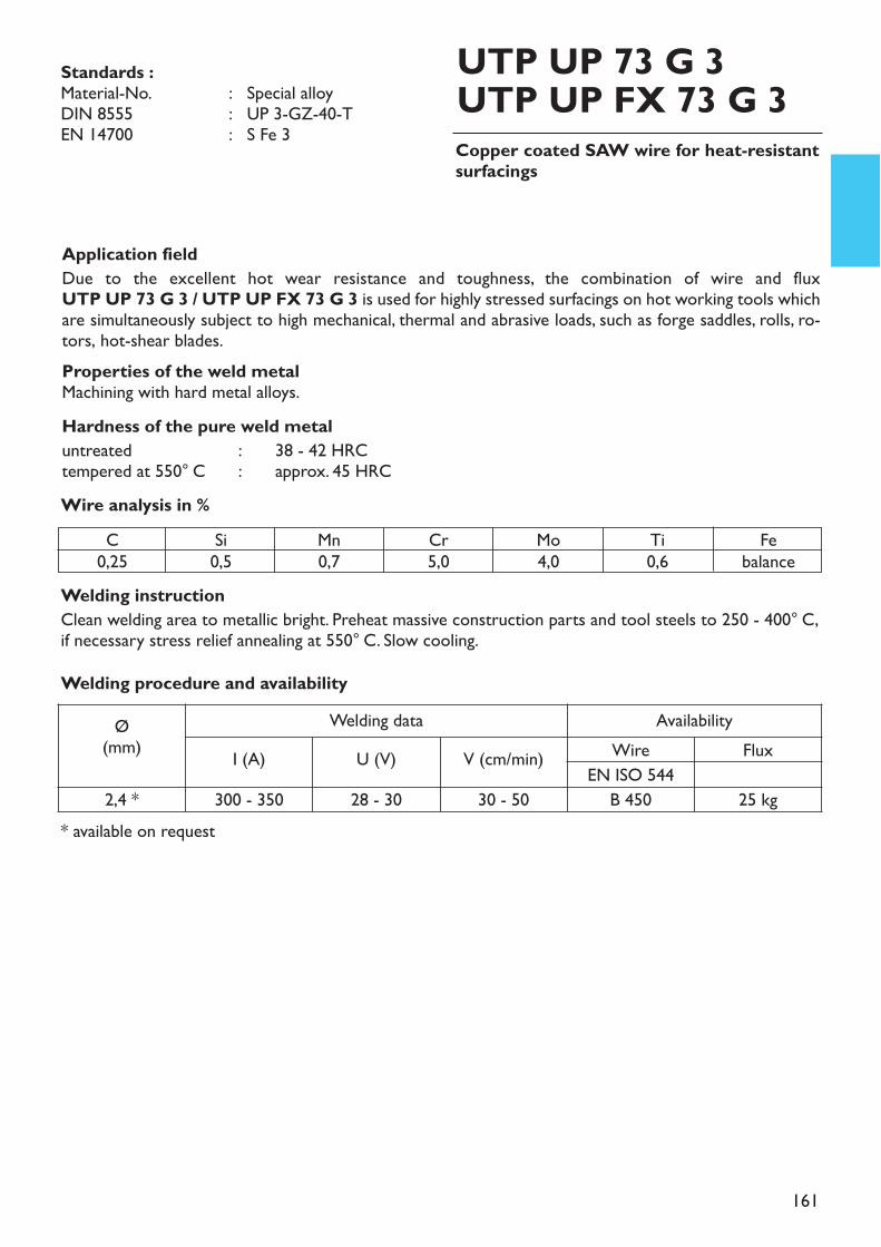
161
Copper coated SAW wire for heat-resistantsurfacings
UTP UP 73 G 3UTP UP FX 73 G 3
Application fieldDue to the excellent hot wear resistance and toughness, the combination of wire and flux UTP UP 73 G 3 / UTP UP FX 73 G 3 is used for highly stressed surfacings on hot working tools whichare simultaneously subject to high mechanical, thermal and abrasive loads, such as forge saddles, rolls, ro-tors, hot-shear blades.Properties of the weld metalMachining with hard metal alloys.Hardness of the pure weld metaluntreated : 38 - 42 HRCtempered at 550° C : approx. 45 HRC
Welding instructionClean welding area to metallic bright. Preheat massive construction parts and tool steels to 250 - 400° C,if necessary stress relief annealing at 550° C. Slow cooling.
Wire analysis in %
Standards :Material-No. : Special alloyDIN 8555 : UP 3-GZ-40-TEN 14700 : S Fe 3
C0,25
Si0,5
Mn0,7
Cr5,0
Mo4,0
Ti0,6
Febalance
* available on request
Welding procedure and availabilityØ
(mm)Welding data Availability
I (A) U (V) V (cm/min) Wire FluxEN ISO 544
2,4 * 300 - 350 28 - 30 30 - 50 B 450 25 kg
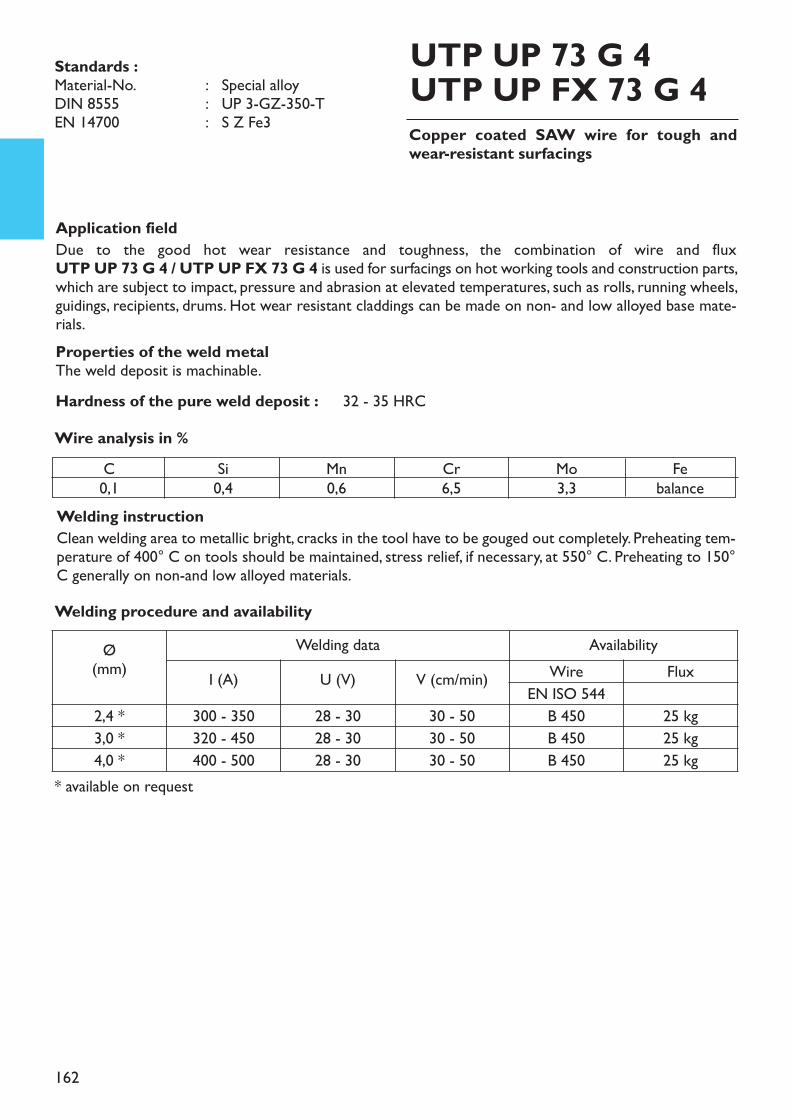
162
Copper coated SAW wire for tough andwear-resistant surfacings
UTP UP 73 G 4UTP UP FX 73 G 4
Application fieldDue to the good hot wear resistance and toughness, the combination of wire and flux UTP UP 73 G 4 / UTP UP FX 73 G 4 is used for surfacings on hot working tools and construction parts,which are subject to impact, pressure and abrasion at elevated temperatures, such as rolls, running wheels,guidings, recipients, drums. Hot wear resistant claddings can be made on non- and low alloyed base mate-rials. Properties of the weld metalThe weld deposit is machinable.Hardness of the pure weld deposit : 32 - 35 HRC
Welding instructionClean welding area to metallic bright, cracks in the tool have to be gouged out completely. Preheating tem-perature of 400° C on tools should be maintained, stress relief, if necessary, at 550° C. Preheating to 150°C generally on non-and low alloyed materials.
Wire analysis in %
Standards :Material-No. : Special alloyDIN 8555 : UP 3-GZ-350-TEN 14700 : S Z Fe3
C0,1
Si0,4
Mn0,6
Cr6,5
Mo3,3
Febalance
* available on request
Welding procedure and availabilityØ
(mm)Welding data Availability
I (A) U (V) V (cm/min) Wire FluxEN ISO 544
2,4 * 300 - 350 28 - 30 30 - 50 B 450 25 kg3,0 * 320 - 450 28 - 30 30 - 50 B 450 25 kg4,0 * 400 - 500 28 - 30 30 - 50 B 450 25 kg
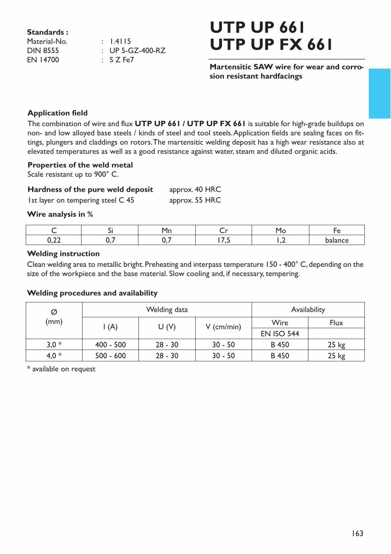
163
Martensitic SAW wire for wear and corro-sion resistant hardfacings
UTP UP 661UTP UP FX 661
Application fieldThe combination of wire and flux UTP UP 661 / UTP UP FX 661 is suitable for high-grade buildups onnon- and low alloyed base steels / kinds of steel and tool steels. Application fields are sealing faces on fit-tings, plungers and claddings on rotors. The martensitic welding deposit has a high wear resistance also atelevated temperatures as well as a good resistance against water, steam and diluted organic acids. Properties of the weld metalScale resistant up to 900° C.Hardness of the pure weld deposit approx. 40 HRC1st layer on tempering steel C 45 approx. 55 HRC
Welding instructionClean welding area to metallic bright. Preheating and interpass temperature 150 - 400° C, depending on thesize of the workpiece and the base material. Slow cooling and, if necessary, tempering.
Wire analysis in %
Standards :Material-No. : 1.4115DIN 8555 : UP 5-GZ-400-RZEN 14700 : S Z Fe7
C0,22
Si0,7
Mn0,7
Cr17,5
Mo1,2
Febalance
Welding procedures and availabilityØ
(mm)Welding data Availability
I (A) U (V) V (cm/min) Wire FluxEN ISO 544
3,0 * 400 - 500 28 - 30 30 - 50 B 450 25 kg4,0 * 500 - 600 28 - 30 30 - 50 B 450 25 kg
* available on request
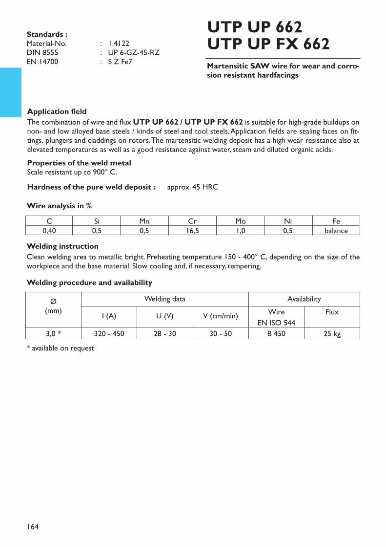
164
Martensitic SAW wire for wear and corro-sion resistant hardfacings
UTP UP 662UTP UP FX 662
Application fieldThe combination of wire and flux UTP UP 662 / UTP UP FX 662 is suitable for high-grade buildups onnon- and low alloyed base steels / kinds of steel and tool steels. Application fields are sealing faces on fit-tings, plungers and claddings on rotors. The martensitic welding deposit has a high wear resistance also atelevated temperatures as well as a good resistance against water, steam and diluted organic acids. Properties of the weld metalScale resistant up to 900° C.Hardness of the pure weld deposit : approx. 45 HRC
Welding instructionClean welding area to metallic bright. Preheating temperature 150 - 400° C, depending on the size of theworkpiece and the base material. Slow cooling and, if necessary, tempering.
Wire analysis in %
Standards :Material-No. : 1.4122DIN 8555 : UP 6-GZ-45-RZEN 14700 : S Z Fe7
C0,40
Si0,5
Mn0,5
Cr16,5
Mo1,0
Ni0,5
Febalance
Welding procedure and availabilityØ
(mm)Welding data Availability
I (A) U (V) V (cm/min) Wire FluxEN ISO 544
3,0 * 320 - 450 28 - 30 30 - 50 B 450 25 kg* available on request
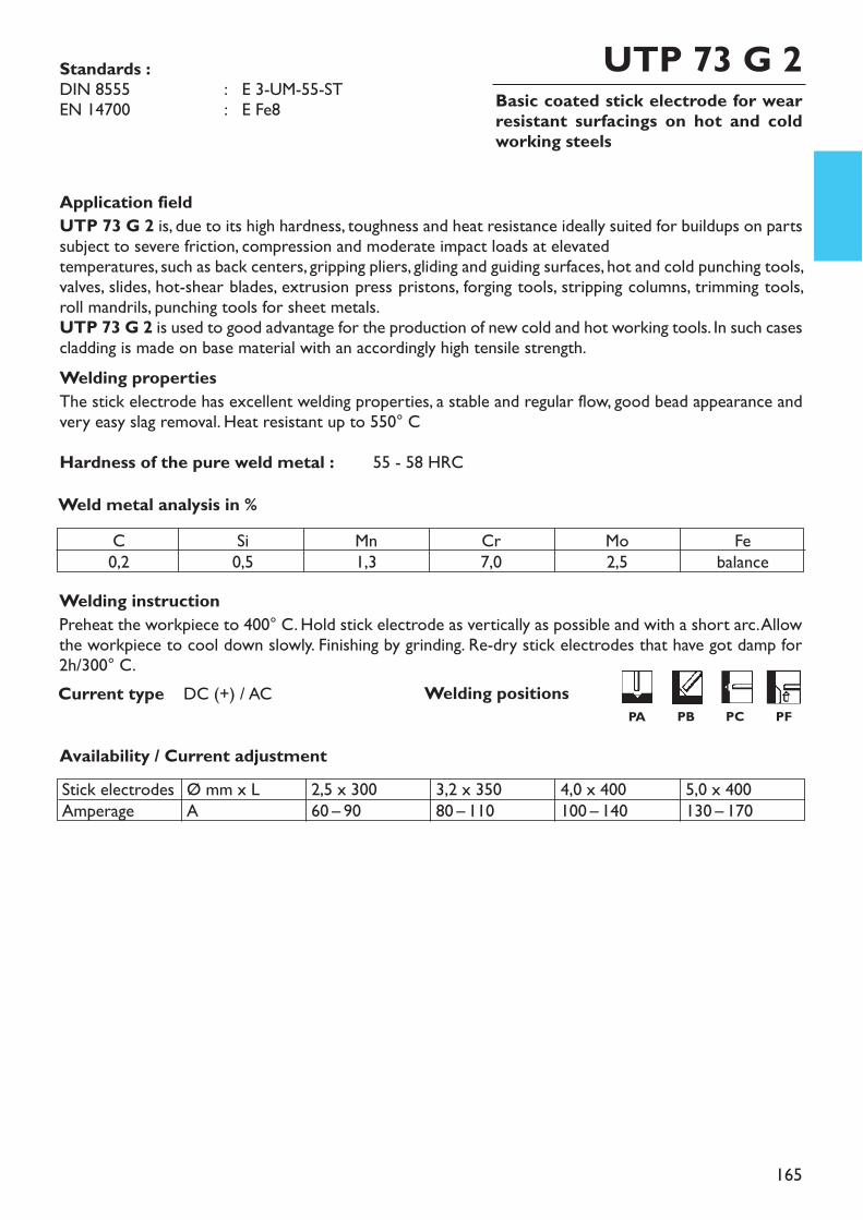
165
Basic coated stick electrode for wearresistant surfacings on hot and coldworking steels
UTP 73 G 2
Welding instructionPreheat the workpiece to 400° C. Hold stick electrode as vertically as possible and with a short arc. Allowthe workpiece to cool down slowly. Finishing by grinding. Re-dry stick electrodes that have got damp for2h/300° C.
Application fieldUTP 73 G 2 is, due to its high hardness, toughness and heat resistance ideally suited for buildups on partssubject to severe friction, compression and moderate impact loads at elevated temperatures, such as back centers, gripping pliers, gliding and guiding surfaces, hot and cold punching tools,valves, slides, hot-shear blades, extrusion press pristons, forging tools, stripping columns, trimming tools,roll mandrils, punching tools for sheet metals.UTP 73 G 2 is used to good advantage for the production of new cold and hot working tools. In such casescladding is made on base material with an accordingly high tensile strength.Welding propertiesThe stick electrode has excellent welding properties, a stable and regular flow, good bead appearance andvery easy slag removal. Heat resistant up to 550° CHardness of the pure weld metal : 55 - 58 HRCWeld metal analysis in %
Availability / Current adjustment
Current type DC (+) / AC
Standards :DIN 8555 : E 3-UM-55-STEN 14700 : E Fe8
C0,2
Si0,5
Mn1,3
Cr7,0
Mo2,5
Febalance
Stick electrodesAmperage
Ø mm x LA
2,5 x 30060 – 90
3,2 x 35080 – 110
4,0 x 400100 – 140
5,0 x 400130 – 170
Welding positionsPA PB PC PF
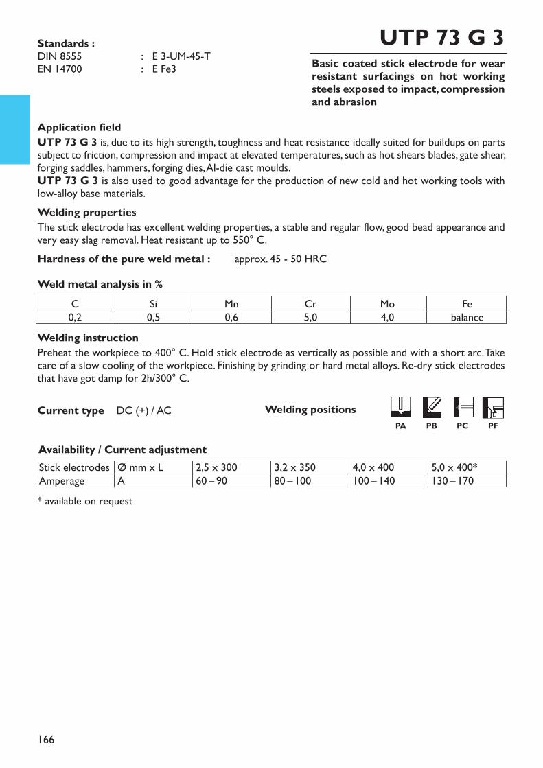
166
Basic coated stick electrode for wearresistant surfacings on hot workingsteels exposed to impact, compressionand abrasion
UTP 73 G 3
Welding instructionPreheat the workpiece to 400° C. Hold stick electrode as vertically as possible and with a short arc. Takecare of a slow cooling of the workpiece. Finishing by grinding or hard metal alloys. Re-dry stick electrodesthat have got damp for 2h/300° C.
* available on request
Application fieldUTP 73 G 3 is, due to its high strength, toughness and heat resistance ideally suited for buildups on partssubject to friction, compression and impact at elevated temperatures, such as hot shears blades, gate shear,forging saddles, hammers, forging dies, Al-die cast moulds.UTP 73 G 3 is also used to good advantage for the production of new cold and hot working tools withlow-alloy base materials.Welding propertiesThe stick electrode has excellent welding properties, a stable and regular flow, good bead appearance andvery easy slag removal. Heat resistant up to 550° C.Hardness of the pure weld metal : approx. 45 - 50 HRCWeld metal analysis in %
Availability / Current adjustment
Current type DC (+) / AC
Standards :DIN 8555 : E 3-UM-45-TEN 14700 : E Fe3
C0,2
Si0,5
Mn0,6
Cr5,0
Mo4,0
Febalance
Stick electrodesAmperage
Ø mm x LA
2,5 x 30060 – 90
3,2 x 35080 – 100
4,0 x 400100 – 140
5,0 x 400*130 – 170
Welding positionsPA PB PC PF
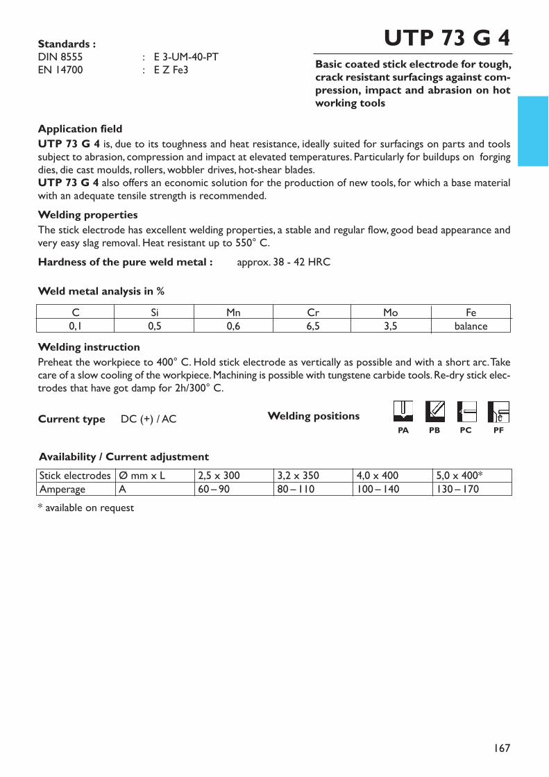
167
Basic coated stick electrode for tough,crack resistant surfacings against com-pression, impact and abrasion on hotworking tools
UTP 73 G 4
Welding instructionPreheat the workpiece to 400° C. Hold stick electrode as vertically as possible and with a short arc. Takecare of a slow cooling of the workpiece. Machining is possible with tungstene carbide tools. Re-dry stick elec-trodes that have got damp for 2h/300° C.
* available on request
Application fieldUTP 73 G 4 is, due to its toughness and heat resistance, ideally suited for surfacings on parts and toolssubject to abrasion, compression and impact at elevated temperatures. Particularly for buildups on forgingdies, die cast moulds, rollers, wobbler drives, hot-shear blades.UTP 73 G 4 also offers an economic solution for the production of new tools, for which a base materialwith an adequate tensile strength is recommended.Welding propertiesThe stick electrode has excellent welding properties, a stable and regular flow, good bead appearance andvery easy slag removal. Heat resistant up to 550° C.Hardness of the pure weld metal : approx. 38 - 42 HRCWeld metal analysis in %
Availability / Current adjustment
Current type DC (+) / AC
Standards :DIN 8555 : E 3-UM-40-PTEN 14700 : E Z Fe3
C0,1
Si0,5
Mn0,6
Cr6,5
Mo3,5
Febalance
Stick electrodesAmperage
Ø mm x LA
2,5 x 30060 – 90
3,2 x 35080 – 110
4,0 x 400100 – 140
5,0 x 400*130 – 170
Welding positionsPA PB PC PF
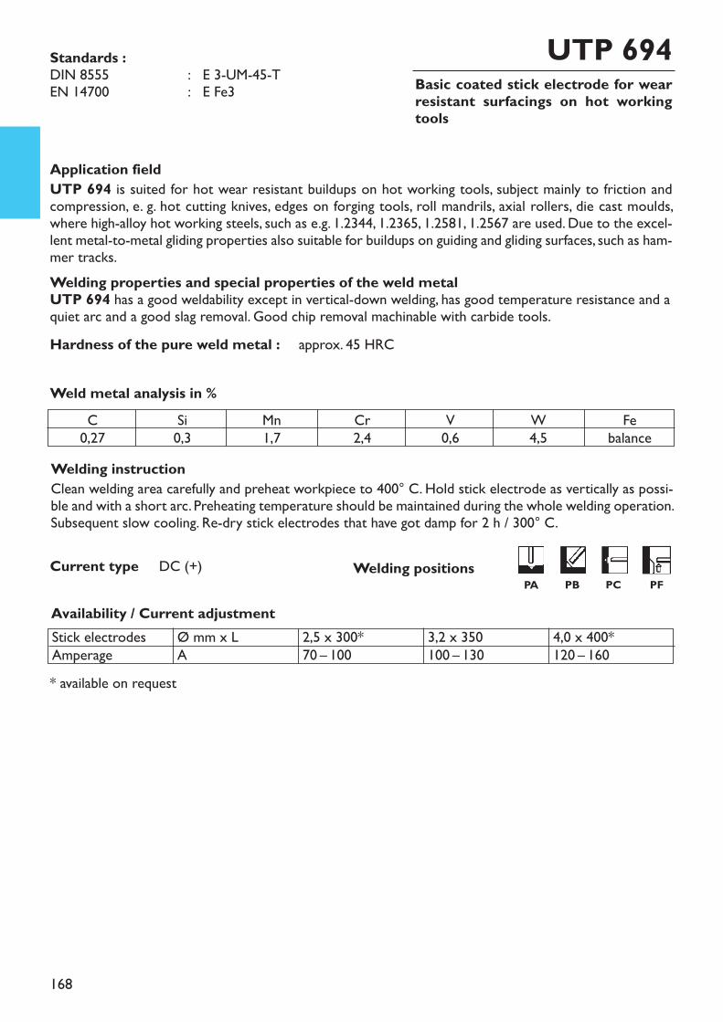
168
Basic coated stick electrode for wearresistant surfacings on hot workingtools
UTP 694
Welding instructionClean welding area carefully and preheat workpiece to 400° C. Hold stick electrode as vertically as possi-ble and with a short arc. Preheating temperature should be maintained during the whole welding operation.Subsequent slow cooling. Re-dry stick electrodes that have got damp for 2 h / 300° C.
* available on request
Application fieldUTP 694 is suited for hot wear resistant buildups on hot working tools, subject mainly to friction andcompression, e. g. hot cutting knives, edges on forging tools, roll mandrils, axial rollers, die cast moulds,where high-alloy hot working steels, such as e.g. 1.2344, 1.2365, 1.2581, 1.2567 are used. Due to the excel-lent metal-to-metal gliding properties also suitable for buildups on guiding and gliding surfaces, such as ham-mer tracks.Welding properties and special properties of the weld metalUTP 694 has a good weldability except in vertical-down welding, has good temperature resistance and aquiet arc and a good slag removal. Good chip removal machinable with carbide tools.Hardness of the pure weld metal : approx. 45 HRC
Weld metal analysis in %
Availability / Current adjustment
Current type DC (+)
Standards :DIN 8555 : E 3-UM-45-TEN 14700 : E Fe3
C0,27
Si0,3
Mn1,7
Cr2,4
V0,6
W4,5
Febalance
Stick electrodesAmperage
Ø mm x LA
2,5 x 300*70 – 100
3,2 x 350100 – 130
4,0 x 400*120 – 160
Welding positionsPA PB PC PF
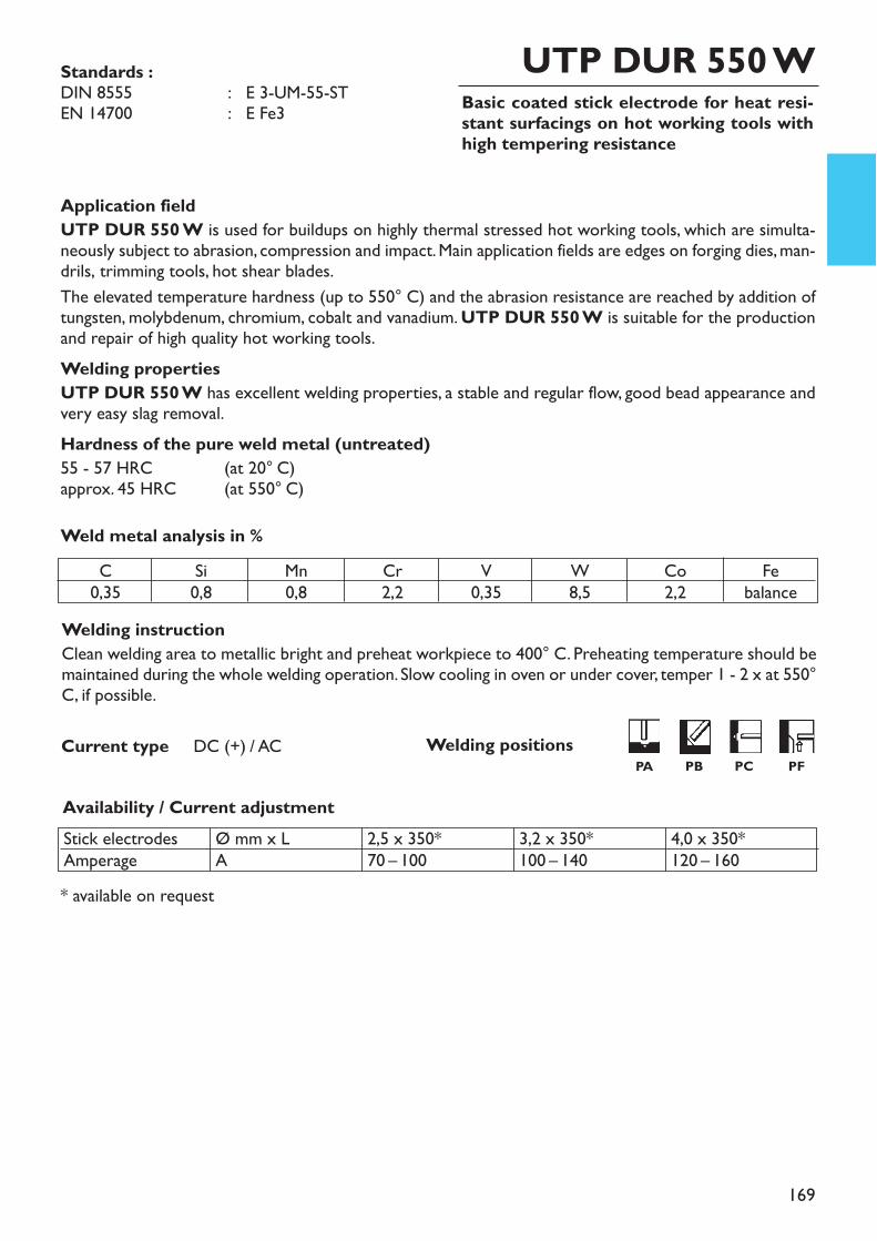
169
Basic coated stick electrode for heat resi-stant surfacings on hot working tools withhigh tempering resistance
UTP DUR 550 W
Welding instructionClean welding area to metallic bright and preheat workpiece to 400° C. Preheating temperature should bemaintained during the whole welding operation. Slow cooling in oven or under cover, temper 1 - 2 x at 550°C, if possible.
* available on request
Application fieldUTP DUR 550 W is used for buildups on highly thermal stressed hot working tools, which are simulta-neously subject to abrasion, compression and impact. Main application fields are edges on forging dies, man-drils, trimming tools, hot shear blades.The elevated temperature hardness (up to 550° C) and the abrasion resistance are reached by addition oftungsten, molybdenum, chromium, cobalt and vanadium. UTP DUR 550 W is suitable for the productionand repair of high quality hot working tools.Welding propertiesUTP DUR 550 W has excellent welding properties, a stable and regular flow, good bead appearance andvery easy slag removal.Hardness of the pure weld metal (untreated)55 - 57 HRC (at 20° C)approx. 45 HRC (at 550° C)Weld metal analysis in %
Availability / Current adjustment
Current type DC (+) / AC
Standards :DIN 8555 : E 3-UM-55-STEN 14700 : E Fe3
C0,35
Si0,8
Mn0,8
Cr2,2
V0,35
W8,5
Co2,2
Febalance
Stick electrodesAmperage
Ø mm x LA
2,5 x 350*70 – 100
3,2 x 350*100 – 140
4,0 x 350*120 – 160
Welding positionsPA PB PC PF
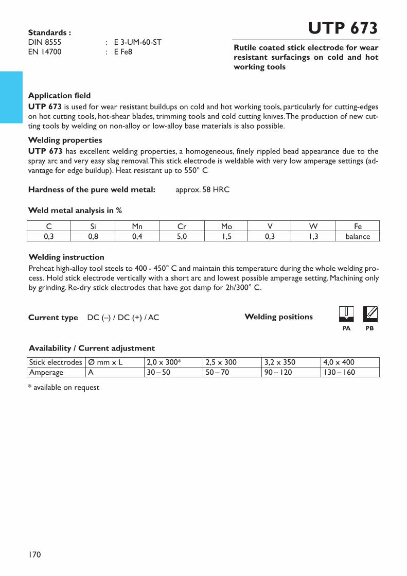
170
Rutile coated stick electrode for wearresistant surfacings on cold and hotworking tools
UTP 673
Welding instructionPreheat high-alloy tool steels to 400 - 450° C and maintain this temperature during the whole welding pro-cess. Hold stick electrode vertically with a short arc and lowest possible amperage setting. Machining onlyby grinding. Re-dry stick electrodes that have got damp for 2h/300° C.
* available on request
Application fieldUTP 673 is used for wear resistant buildups on cold and hot working tools, particularly for cutting-edgeson hot cutting tools, hot-shear blades, trimming tools and cold cutting knives. The production of new cut-ting tools by welding on non-alloy or low-alloy base materials is also possible.Welding propertiesUTP 673 has excellent welding properties, a homogeneous, finely rippled bead appearance due to thespray arc and very easy slag removal. This stick electrode is weldable with very low amperage settings (ad-vantage for edge buildup). Heat resistant up to 550° CHardness of the pure weld metal: approx. 58 HRCWeld metal analysis in %
Availability / Current adjustment
Current type DC (–) / DC (+) / AC
Standards :DIN 8555 : E 3-UM-60-STEN 14700 : E Fe8
C0,3
Si0,8
Mn0,4
Cr5,0
Mo1,5
V0,3
W1,3
Febalance
Stick electrodesAmperage
Ø mm x LA
2,0 x 300*30 – 50
2,5 x 30050 – 70
3,2 x 35090 – 120
4,0 x 400130 – 160
Welding positionsPA PB
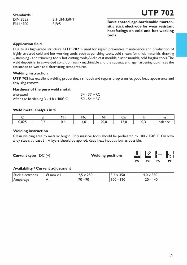
171
Basic coated, age-hardenable marten-sitic stick electrode for wear resistanthardfacings on cold and hot workingtools
UTP 702
Welding instructionClean welding area to metallic bright. Only massive tools should be preheated to 100 - 150° C. On low-alloy steels at least 3 - 4 layers should be applied. Keep heat input as low as possible.
Application fieldDue to its high-grade structure, UTP 702 is used for repair, preventive maintenance and production ofhighly stressed cold and hot working tools, such as punching tools, cold shears for thick materials, drawing-, stamping - and trimming tools, hot cutting tools, Al-die cast moulds, plastic moulds, cold forging tools. Theweld deposit is, in as-welded condition, easily machinable and the subsequent age hardening opitmises theresistance to wear and alternating temperatures.Welding instructionUTP 702 has excellent welding properties, a smooth and regular drop transfer, good bead appearance andeasy slag removal.Hardness of the pure weld metal:untreated: 34 - 37 HRCAfter age hardening 3 - 4 h / 480° C 50 - 54 HRC
Weld metal analysis in %
Availability / Current adjustment
Current type DC (+)
Standards :DIN 8555 : E 3-UM-350-TEN 14700 : E Fe5
C0,025
Si0,2
Mn0,6
Mo4,0
Ni20,0
Co12,0
Ti0,3
Febalance
Stick electrodesAmperage
Ø mm x LA
2,5 x 25070 – 90
3,2 x 350100 – 120
4,0 x 350120 – 140
Welding positionsPA PB PC PF
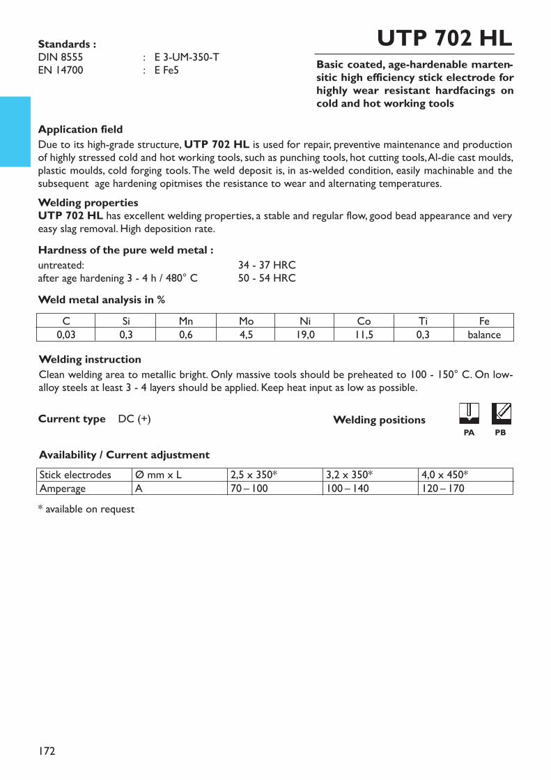
172
Basic coated, age-hardenable marten-sitic high efficiency stick electrode forhighly wear resistant hardfacings oncold and hot working tools
UTP 702 HL
Welding instructionClean welding area to metallic bright. Only massive tools should be preheated to 100 - 150° C. On low-alloy steels at least 3 - 4 layers should be applied. Keep heat input as low as possible.
* available on request
Application fieldDue to its high-grade structure, UTP 702 HL is used for repair, preventive maintenance and productionof highly stressed cold and hot working tools, such as punching tools, hot cutting tools, Al-die cast moulds,plastic moulds, cold forging tools. The weld deposit is, in as-welded condition, easily machinable and thesubsequent age hardening opitmises the resistance to wear and alternating temperatures.Welding propertiesUTP 702 HL has excellent welding properties, a stable and regular flow, good bead appearance and veryeasy slag removal. High deposition rate.Hardness of the pure weld metal :untreated: 34 - 37 HRCafter age hardening 3 - 4 h / 480° C 50 - 54 HRCWeld metal analysis in %
Availability / Current adjustment
Current type DC (+)
C0,03
Si0,3
Mn0,6
Mo4,5
Ni19,0
Co11,5
Ti0,3
Febalance
Stick electrodesAmperage
Ø mm x LA
2,5 x 350*70 – 100
3,2 x 350*100 – 140
4,0 x 450*120 – 170
Standards :DIN 8555 : E 3-UM-350-TEN 14700 : E Fe5
Welding positionsPA PB
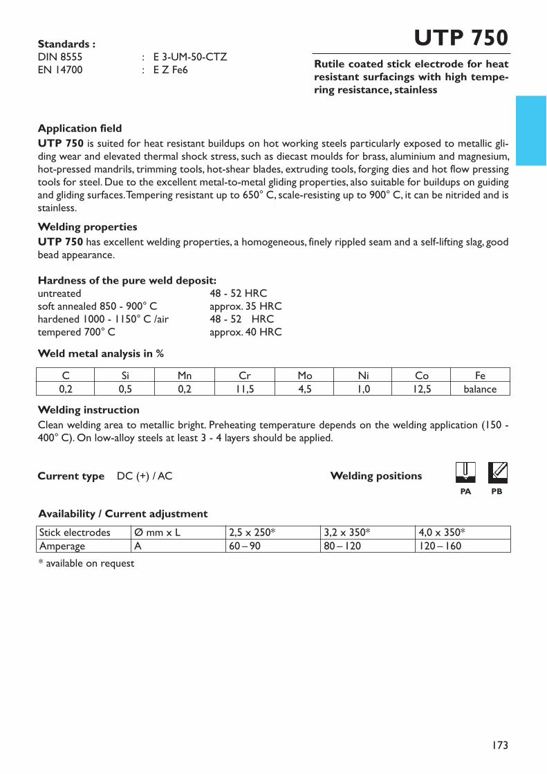
173
Rutile coated stick electrode for heatresistant surfacings with high tempe-ring resistance, stainless
UTP 750
Welding instructionClean welding area to metallic bright. Preheating temperature depends on the welding application (150 -400° C). On low-alloy steels at least 3 - 4 layers should be applied.
* available on request
Application fieldUTP 750 is suited for heat resistant buildups on hot working steels particularly exposed to metallic gli-ding wear and elevated thermal shock stress, such as diecast moulds for brass, aluminium and magnesium,hot-pressed mandrils, trimming tools, hot-shear blades, extruding tools, forging dies and hot flow pressingtools for steel. Due to the excellent metal-to-metal gliding properties, also suitable for buildups on guidingand gliding surfaces. Tempering resistant up to 650° C, scale-resisting up to 900° C, it can be nitrided and isstainless.Welding propertiesUTP 750 has excellent welding properties, a homogeneous, finely rippled seam and a self-lifting slag, goodbead appearance.Hardness of the pure weld deposit:untreated 48 - 52 HRCsoft annealed 850 - 900° C approx. 35 HRChardened 1000 - 1150° C /air 48 - 52 HRCtempered 700° C approx. 40 HRCWeld metal analysis in %
Availability / Current adjustment
Current type DC (+) / AC
Standards :DIN 8555 : E 3-UM-50-CTZEN 14700 : E Z Fe6
C0,2
Si0,5
Mn0,2
Cr11,5
Mo4,5
Ni1,0
Co12,5
Febalance
Stick electrodesAmperage
Ø mm x LA
2,5 x 250*60 – 90
3,2 x 350*80 – 120
4,0 x 350*120 – 160
Welding positionsPA PB
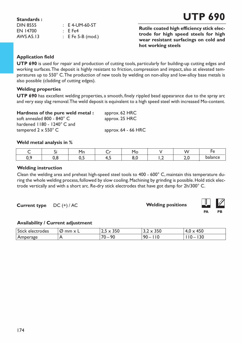
174
Rutile coated high efficiency stick elec-trode for high speed steels for highwear resistant surfacings on cold andhot working steels
UTP 690
Welding instructionClean the welding area and preheat high-speed steel tools to 400 - 600° C, maintain this temperature du-ring the whole welding process, followed by slow cooling. Machining by grinding is possible. Hold stick elec-trode vertically and with a short arc. Re-dry stick electrodes that have got damp for 2h/300° C.
Application fieldUTP 690 is used for repair and production of cutting tools, particularly for building-up cutting edges andworking surfaces. The deposit is highly resistant to friction, compression and impact, also at elevated tem-peratures up to 550° C. The production of new tools by welding on non-alloy and low-alloy base metals isalso possible (cladding of cutting edges).Welding propertiesUTP 690 has excellent welding properties, a smooth, finely rippled bead appearance due to the spray arcand very easy slag removal. The weld deposit is equivalent to a high speed steel with increased Mo-content.Hardness of the pure weld metal : approx. 62 HRCsoft annealed 800 - 840° C approx. 25 HRChardened 1180 - 1240° C andtempered 2 x 550° C approx. 64 - 66 HRCWeld metal analysis in %
Availability / Current adjustment
Current type DC (+) / AC
Standards :DIN 8555 : E 4-UM-60-STEN 14700 : E Fe4AWS A5.13 : E Fe 5-B (mod.)
C0,9
Si0,8
Mn0,5
Cr4,5
Mo8,0
V1,2
W2,0
Febalance
Stick electrodesAmperage
Ø mm x LA
2,5 x 35070 – 90
3,2 x 35090 – 110
4,0 x 450110 – 130
Welding positionsPA PB
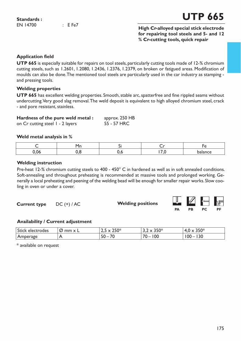
175
High Cr-alloyed special stick electrodefor repairing tool steels and 5- and 12% Cr-cutting tools, quick repair
UTP 665
Welding instructionPre-heat 12-% chromium cutting steels to 400 - 450° C in hardened as well as in soft annealed conditions.Soft-annealing and throughout preheating is recommended at massive tools and prolonged working. Ge-nerally a local preheating and peening of the welding bead will be enough for smaller repair works. Slow coo-ling in oven or under a cover.
* available on request
Application fieldUTP 665 is especially suitable for repairs on tool steels, particularly cutting tools made of 12-% chromiumcutting steels, such as 1.2601, 1.2080, 1.2436, 1.2376, 1.2379, on broken or fatigued areas. Modification ofmoulds can also be done. The mentioned tool steels are particularly used in the car industry as stamping -and pressing tools.Welding propertiesUTP 665 has excellent welding properties. Smooth, stable arc, spatterfree and fine rippled seams withoutundercutting. Very good slag removal. The weld deposit is equivalent to high alloyed chromium steel, crack- and pore resistant, stainless.Hardness of the pure weld metal : approx. 250 HBon Cr cutting steel 1 - 2 layers 55 - 57 HRCWeld metal analysis in %
Availability / Current adjustment
Current type DC (+) / AC
Standards :EN 14700 : E Fe7
C0,06
Mn0,8
Si0,6
Cr17,0
Febalance
Stick electrodesAmperage
Ø mm x LA
2,5 x 250*50 – 70
3,2 x 350*70 – 100
4,0 x 350*100 – 130
Welding positionsPA PB PC PF
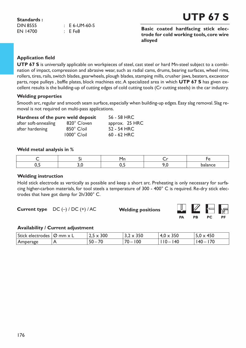
176
Basic coated hardfacing stick elec-trode for cold working tools, core wirealloyed
UTP 67 S
Welding instructionHold stick electrode as vertically as possible and keep a short arc. Preheating is only necessary for surfa-cing higher-carbon materials, for tool steels a temperature of 300 - 400° C is required. Re-dry stick elec-trodes that have got damp for 2h/300° C.
Application fieldUTP 67 S is universally applicable on workpieces of steel, cast steel or hard Mn-steel subject to a combi-nation of impact, compression and abrasive wear, such as radial cams, drums, bearing surfaces, wheel rims,rollers, tires, rails, switch blades, gearwheels, plough blades, stamping mills, crusher jaws, beaters, excavatorparts, rope pulleys , baffle plates, block machines etc. A specialized area in which UTP 67 S has given ex-cellent results is the building-up of cutting edges of cold cutting tools (Cr cutting steels) in the car industry.Welding propertiesSmooth arc, regular and smooth seam surface, especially when building-up edges. Easy slag removal. Slag re-moval is not required on multi-pass applications.Hardness of the pure weld deposit 56 - 58 HRCafter soft-annealing 1 820° C/oven approx. 25 HRCafter hardening 1850° C/oil 52 - 54 HRC
1000° C/oil 60 - 62 HRC
Weld metal analysis in %
Availability / Current adjustment
Current type DC (–) / DC (+) / AC
Standards :DIN 8555 : E 6-UM-60-SEN 14700 : E Fe8
C0,5
Si3,0
Mn0,5
Cr9,0
Febalance
Stick electrodesAmperage
Ø mm x LA
2,5 x 30050 – 70
3,2 x 35070 – 100
4,0 x 350110 – 140
5,0 x 450140 – 170
Welding positionsPA PB PC PF
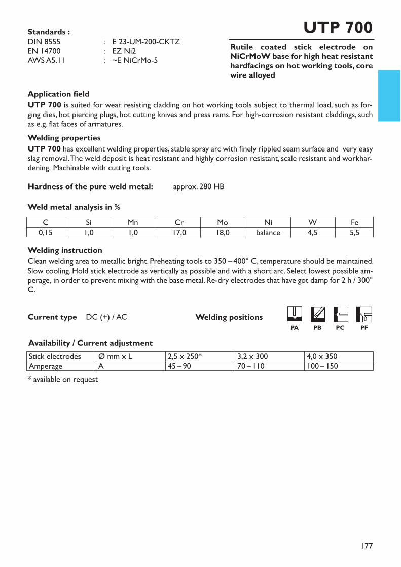
177
Rutile coated stick electrode onNiCrMoW base for high heat resistanthardfacings on hot working tools, corewire alloyed
UTP 700
Application fieldUTP 700 is suited for wear resisting cladding on hot working tools subject to thermal load, such as for-ging dies, hot piercing plugs, hot cutting knives and press rams. For high-corrosion resistant claddings, suchas e.g. flat faces of armatures.Welding propertiesUTP 700 has excellent welding properties, stable spray arc with finely rippled seam surface and very easyslag removal. The weld deposit is heat resistant and highly corrosion resistant, scale resistant and workhar-dening. Machinable with cutting tools.Hardness of the pure weld metal: approx. 280 HB
Welding instructionClean welding area to metallic bright. Preheating tools to 350 – 400° C, temperature should be maintained.Slow cooling. Hold stick electrode as vertically as possible and with a short arc. Select lowest possible am-perage, in order to prevent mixing with the base metal. Re-dry electrodes that have got damp for 2 h / 300°C.
* available on request
Weld metal analysis in %
Availability / Current adjustment
Current type DC (+) / AC
Standards :DIN 8555 : E 23-UM-200-CKTZEN 14700 : EZ Ni2AWS A5.11 : ~E NiCrMo-5
C0,15
Si1,0
Mn1,0
Cr17,0
Mo18,0
Nibalance
W4,5
Fe5,5
Stick electrodesAmperage
Ø mm x LA
2,5 x 250*45 – 90
3,2 x 30070 – 110
4,0 x 350100 – 150
Welding positionsPA PB PC PF
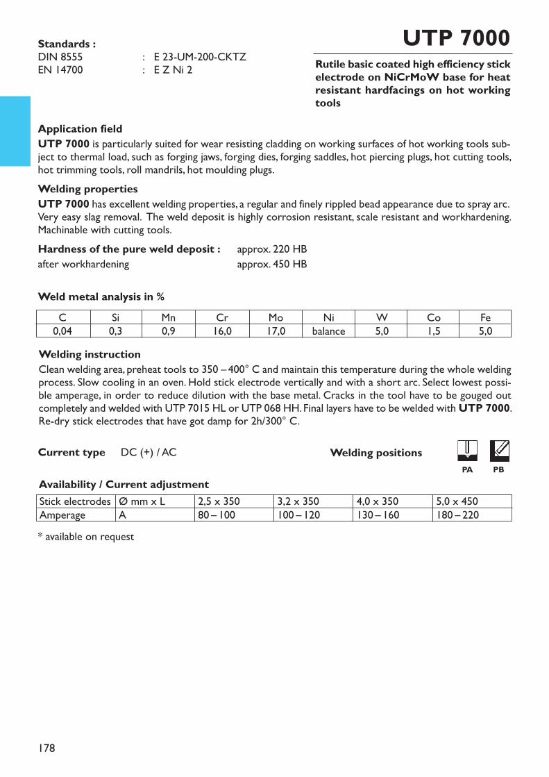
178
Rutile basic coated high efficiency stickelectrode on NiCrMoW base for heatresistant hardfacings on hot workingtools
UTP 7000
Application fieldUTP 7000 is particularly suited for wear resisting cladding on working surfaces of hot working tools sub-ject to thermal load, such as forging jaws, forging dies, forging saddles, hot piercing plugs, hot cutting tools,hot trimming tools, roll mandrils, hot moulding plugs.Welding propertiesUTP 7000 has excellent welding properties, a regular and finely rippled bead appearance due to spray arc.Very easy slag removal. The weld deposit is highly corrosion resistant, scale resistant and workhardening.Machinable with cutting tools.Hardness of the pure weld deposit : approx. 220 HBafter workhardening approx. 450 HB
Welding instructionClean welding area, preheat tools to 350 – 400° C and maintain this temperature during the whole weldingprocess. Slow cooling in an oven. Hold stick electrode vertically and with a short arc. Select lowest possi-ble amperage, in order to reduce dilution with the base metal. Cracks in the tool have to be gouged outcompletely and welded with UTP 7015 HL or UTP 068 HH. Final layers have to be welded with UTP 7000.Re-dry stick electrodes that have got damp for 2h/300° C.
Weld metal analysis in %
Availability / Current adjustment
Current type DC (+) / AC
* available on request
Standards :DIN 8555 : E 23-UM-200-CKTZEN 14700 : E Z Ni 2
Stick electrodesAmperage
Ø mm x LA
2,5 x 35080 – 100
3,2 x 350100 – 120
4,0 x 350130 – 160
5,0 x 450180 – 220
C0,04
Si0,3
Mn0,9
Cr16,0
Mo17,0
Nibalance
W5,0
Co1,5
Fe5,0
Welding positionsPA PB
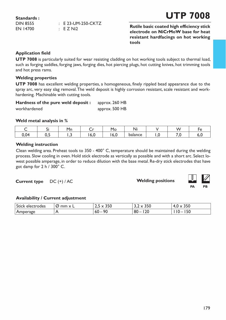
179
Rutile basic coated high efficiency stickelectrode on NiCrMoW base for heatresistant hardfacings on hot workingtools
UTP 7008
Application fieldUTP 7008 is particularly suited for wear resisting cladding on hot working tools subject to thermal load,such as forging saddles, forging jaws, forging dies, hot piercing plugs, hot cutting knives, hot trimming toolsand hot press rams.Welding propertiesUTP 7008 has excellent welding properties, a homogeneous, finely rippled bead appearance due to thespray arc, very easy slag removal. The weld deposit is highly corrosion resistant, scale resistant and work-hardening. Machinable with cutting tools.Hardness of the pure weld deposit : approx. 260 HBworkhardened approx. 500 HB
Welding instructionClean welding area. Preheat tools to 350 - 400° C, temperature should be maintained during the weldingprocess. Slow cooling in oven. Hold stick electrode as vertically as possible and with a short arc. Select lo-west possible amperage, in order to reduce dilution with the base metal. Re-dry stick electrodes that havegot damp for 2 h / 300° C.
Weld metal analysis in %
Availability / Current adjustment
Current type DC (+) / AC
Standards :DIN 8555 : E 23-UM-250-CKTZEN 14700 : E Z Ni2
C0,04
Si0,5
Mn1,3
Cr16,0
Mo16,0
Nibalance
V1,0
W7,0
Fe6,0
Stick electrodesAmperage
Ø mm x LA
2,5 x 35060 – 90
3,2 x 35080 – 120
4,0 x 350110 – 150
Welding positionsPA PB
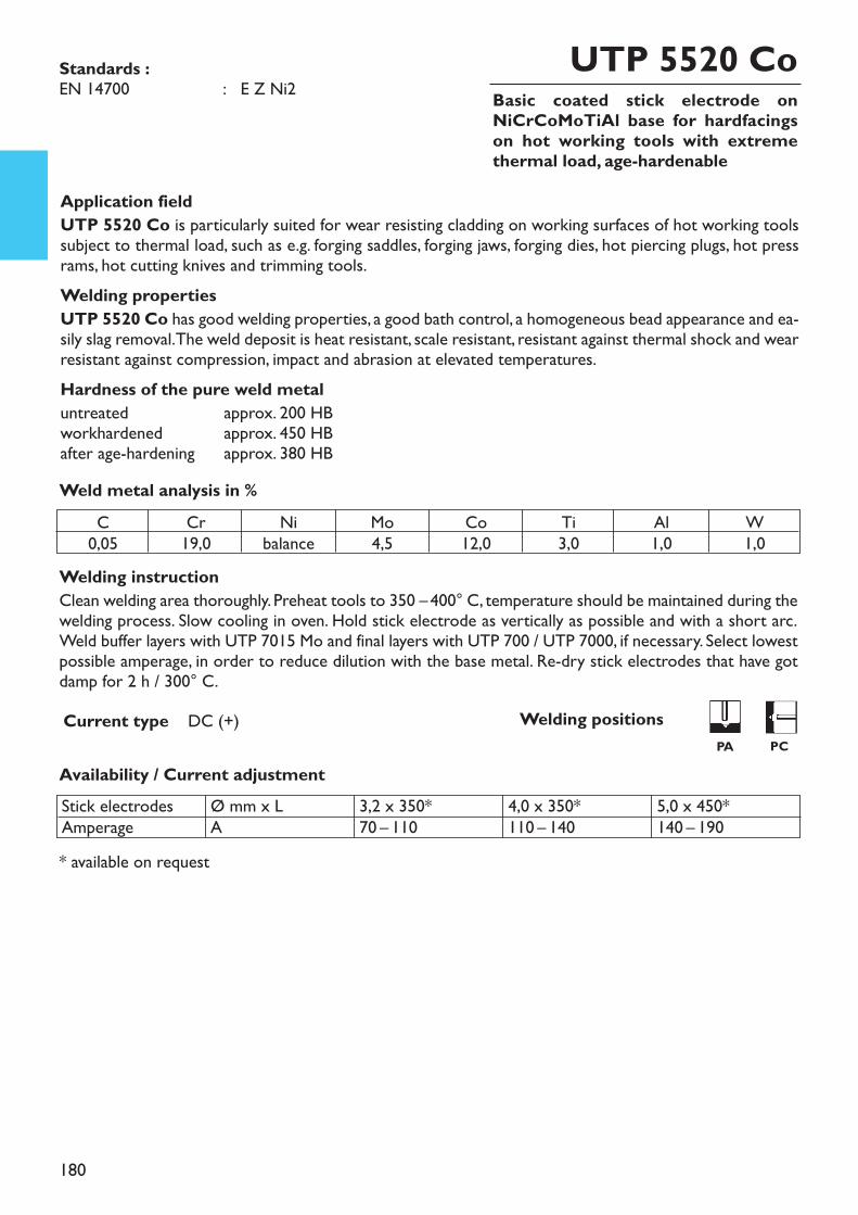
180
Basic coated stick electrode onNiCrCoMoTiAl base for hardfacingson hot working tools with extremethermal load, age-hardenable
UTP 5520 Co
Welding instructionClean welding area thoroughly. Preheat tools to 350 –400° C, temperature should be maintained during thewelding process. Slow cooling in oven. Hold stick electrode as vertically as possible and with a short arc.Weld buffer layers with UTP 7015 Mo and final layers with UTP 700 / UTP 7000, if necessary. Select lowestpossible amperage, in order to reduce dilution with the base metal. Re-dry stick electrodes that have gotdamp for 2 h / 300° C.
* available on request
Availability / Current adjustment
Current type DC (+)
Application fieldUTP 5520 Co is particularly suited for wear resisting cladding on working surfaces of hot working toolssubject to thermal load, such as e.g. forging saddles, forging jaws, forging dies, hot piercing plugs, hot pressrams, hot cutting knives and trimming tools.Welding properties UTP 5520 Co has good welding properties, a good bath control, a homogeneous bead appearance and ea-sily slag removal. The weld deposit is heat resistant, scale resistant, resistant against thermal shock and wearresistant against compression, impact and abrasion at elevated temperatures.Hardness of the pure weld metaluntreated approx. 200 HBworkhardened approx. 450 HBafter age-hardening approx. 380 HBWeld metal analysis in %
Standards :EN 14700 : E Z Ni2
C0,05
Cr19,0
Nibalance
Mo4,5
Co12,0
Ti3,0
Al1,0
W1,0
Stick electrodesAmperage
Ø mm x LA
3,2 x 350*70 – 110
4,0 x 350*110 – 140
5,0 x 450*140 – 190
Welding positionsPA PC
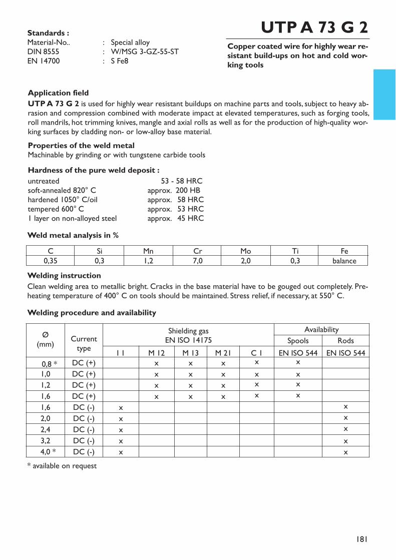
181
Copper coated wire for highly wear re-sistant build-ups on hot and cold wor-king tools
Welding instructionClean welding area to metallic bright. Cracks in the base material have to be gouged out completely. Pre-heating temperature of 400° C on tools should be maintained. Stress relief, if necessary, at 550° C.
Application fieldUTP A 73 G 2 is used for highly wear resistant buildups on machine parts and tools, subject to heavy ab-rasion and compression combined with moderate impact at elevated temperatures, such as forging tools,roll mandrils, hot trimming knives, mangle and axial rolls as well as for the production of high-quality wor-king surfaces by cladding non- or low-alloy base material. Properties of the weld metalMachinable by grinding or with tungstene carbide toolsHardness of the pure weld deposit :untreated 53 - 58 HRCsoft-annealed 820° C approx. 200 HBhardened 1050° C/oil approx. 258 HRCtempered 600° C approx. 253 HRC1 layer on non-alloyed steel approx. 245 HRCWeld metal analysis in %
UTP A 73 G 2
* available on request
Standards :Material-No.. : Special alloyDIN 8555 : W/MSG 3-GZ-55-STEN 14700 : S Fe8
C0,35
Si0,3
Mn1,2
Cr7,0
Mo2,0
Ti0,3
Febalance
Welding procedure and availability
Ø(mm) Current
typeShielding gasEN ISO 14175
AvailabilitySpools Rods
I 1 M 12 M 13 M 21 C 1 EN ISO 544 EN ISO 5440,8 * DC (+) x x x x x1,0 DC (+) x x x x x1,2 DC (+) x x x x x1,6 DC (+) x x x x x1,6 DC (-) x x2,0 DC (-) x x2,4 DC (-) x x3,2 DC (-) x x4,0 * DC (-) x x
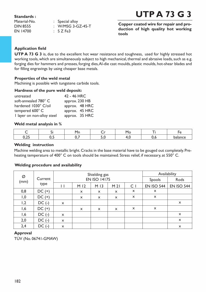
182
Copper coated wire for repair and pro-duction of high quality hot workingtools
Welding instructionMachine welding area to metallic bright. Cracks in the base material have to be gouged out completely. Pre-heating temperature of 400° C on tools should be maintained. Stress relief, if necessary, at 550° C.
Application fieldUTP A 73 G 3 is, due to the excellent hot wear resistance and toughness, used for highly stressed hotworking tools, which are simultaneously subject to high mechanical, thermal and abrasive loads, such as e.g.forging dies for hammers and presses, forging dies, Al-die cast moulds, plastic moulds, hot-shear blades andfor filling engravings by using cheaper base metals. Properties of the weld metalMachining is possible with tungstene carbide tools.Hardness of the pure weld deposit:untreated 42 - 46 HRCsoft-annealed 780° C approx. 230 HBhardened 1030° C/oil approx. 248 HRCtempered 600° C approx. 245 HRC1 layer on non-alloy steel approx. 235 HRCWeld metal analysis in %
UTP A 73 G 3Standards :Material-No. : Special alloyDIN 8555 : W/MSG 3-GZ-45-TEN 14700 : S Z Fe3
C0,25
Si0,5
Mn0,7
Cr5,0
Mo4,0
Ti0,6
Febalance
ApprovalTÜV (No. 06741-GMAW)
Welding procedure and availability
Ø(mm) Current
typeShielding gasEN ISO 14175
AvailabilitySpools Rods
I 1 M 12 M 13 M 21 C 1 EN ISO 544 EN ISO 5440,8 DC (+) x x x x x1,0 DC (+) x x x x x1,2 DC (-) x x1,6 DC (+) x x x x x1,6 DC (-) x x2,0 DC (-) x x2,4 DC (-) x x
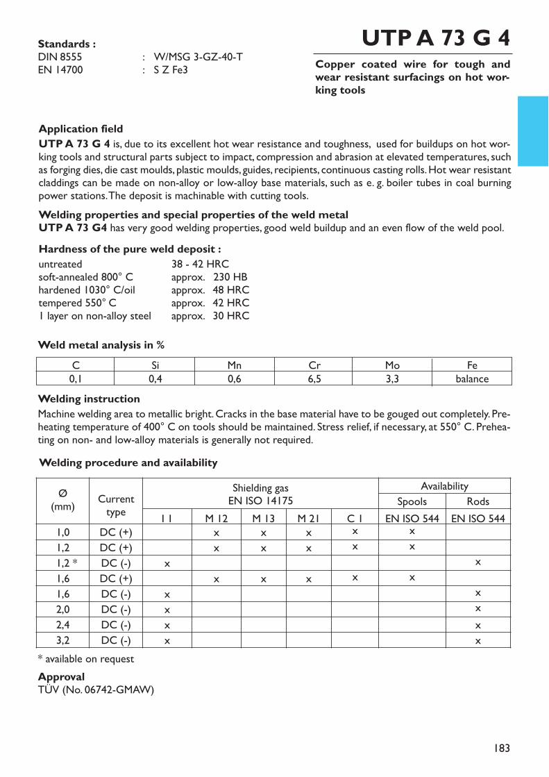
183
Copper coated wire for tough andwear resistant surfacings on hot wor-king tools
Welding instructionMachine welding area to metallic bright. Cracks in the base material have to be gouged out completely. Pre-heating temperature of 400° C on tools should be maintained. Stress relief, if necessary, at 550° C. Prehea-ting on non- and low-alloy materials is generally not required.
Application fieldUTP A 73 G 4 is, due to its excellent hot wear resistance and toughness, used for buildups on hot wor-king tools and structural parts subject to impact, compression and abrasion at elevated temperatures, suchas forging dies, die cast moulds, plastic moulds, guides, recipients, continuous casting rolls. Hot wear resistantcladdings can be made on non-alloy or low-alloy base materials, such as e. g. boiler tubes in coal burningpower stations. The deposit is machinable with cutting tools.Welding properties and special properties of the weld metalUTP A 73 G4 has very good welding properties, good weld buildup and an even flow of the weld pool.Hardness of the pure weld deposit :untreated 38 - 42 HRCsoft-annealed 800° C approx. 230 HBhardened 1030° C/oil approx. 248 HRCtempered 550° C approx. 242 HRC1 layer on non-alloy steel approx. 230 HRCWeld metal analysis in %
UTP A 73 G 4Standards :DIN 8555 : W/MSG 3-GZ-40-TEN 14700 : S Z Fe3
C0,1
Si0,4
Mn0,6
Cr6,5
Mo3,3
Febalance
ApprovalTÜV (No. 06742-GMAW)
* available on request
Welding procedure and availability
Ø(mm) Current
typeShielding gasEN ISO 14175
AvailabilitySpools Rods
I 1 M 12 M 13 M 21 C 1 EN ISO 544 EN ISO 5441,0 DC (+) x x x x x1,2 DC (+) x x x x x1,2 * DC (-) x x1,6 DC (+) x x x x x1,6 DC (-) x x2,0 DC (-) x x2,4 DC (-) x x3,2 DC (-) x x
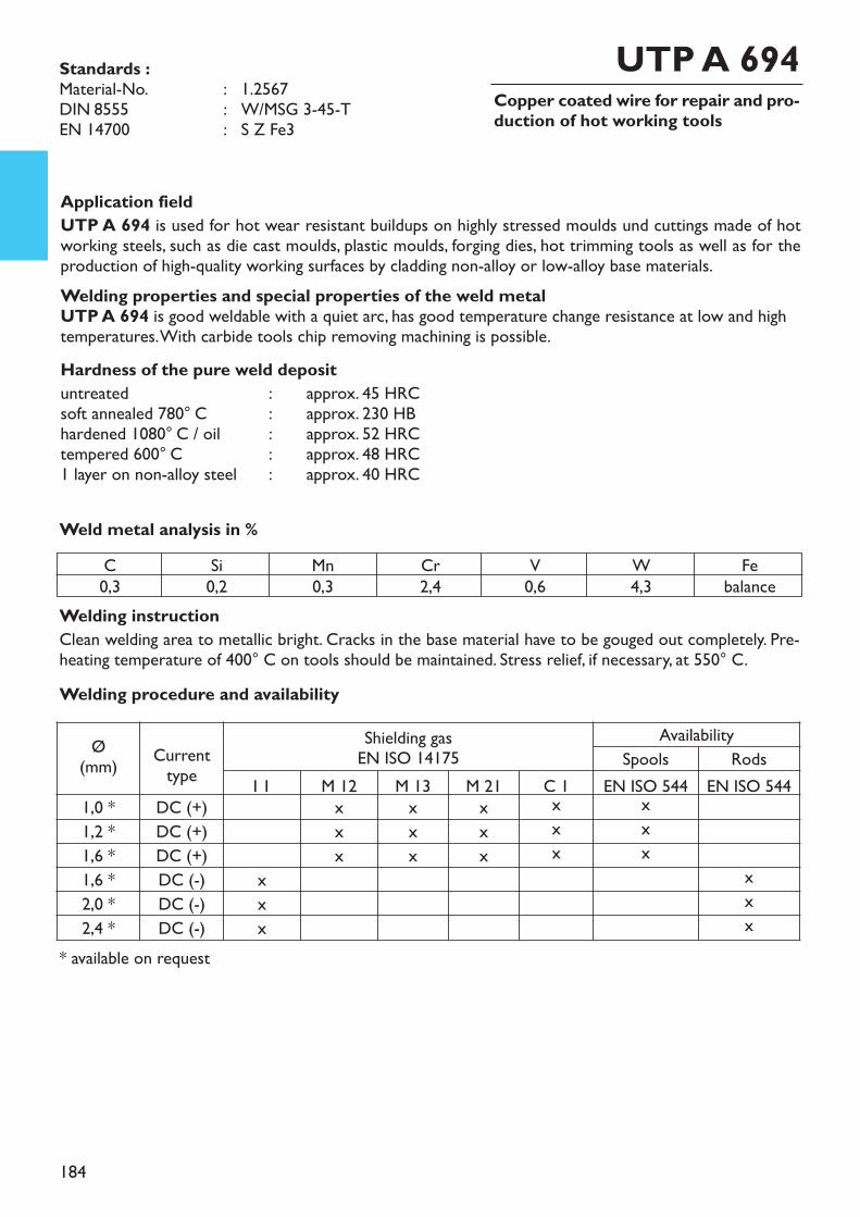
184
Copper coated wire for repair and pro-duction of hot working tools
Welding instructionClean welding area to metallic bright. Cracks in the base material have to be gouged out completely. Pre-heating temperature of 400° C on tools should be maintained. Stress relief, if necessary, at 550° C.
* available on request
Application fieldUTP A 694 is used for hot wear resistant buildups on highly stressed moulds und cuttings made of hotworking steels, such as die cast moulds, plastic moulds, forging dies, hot trimming tools as well as for theproduction of high-quality working surfaces by cladding non-alloy or low-alloy base materials.Welding properties and special properties of the weld metalUTP A 694 is good weldable with a quiet arc, has good temperature change resistance at low and hightemperatures. With carbide tools chip removing machining is possible.Hardness of the pure weld deposituntreated : approx. 45 HRCsoft annealed 780° C : approx. 230 HBhardened 1080° C / oil : approx. 52 HRCtempered 600° C : approx. 48 HRC1 layer on non-alloy steel : approx. 40 HRC
Weld metal analysis in %
UTP A 694Standards :Material-No. : 1.2567DIN 8555 : W/MSG 3-45-TEN 14700 : S Z Fe3
C0,3
Si0,2
Mn0,3
Cr2,4
V0,6
W4,3
Febalance
Welding procedure and availability
Ø(mm) Current
typeShielding gasEN ISO 14175
AvailabilitySpools Rods
I 1 M 12 M 13 M 21 C 1 EN ISO 544 EN ISO 5441,0 * DC (+) x x x x x1,2 * DC (+) x x x x x1,6 * DC (+) x x x x x1,6 * DC (-) x x2,0 * DC (-) x x2,4 * DC (-) x x
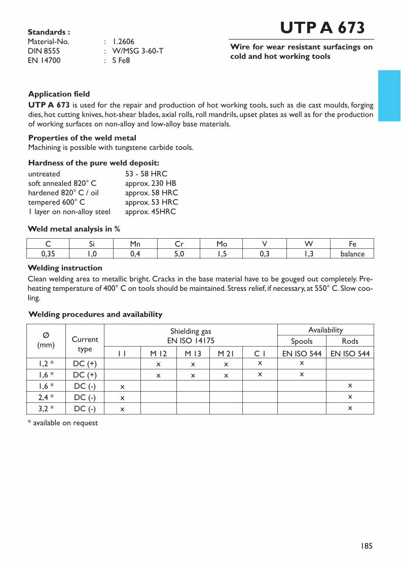
185
Wire for wear resistant surfacings oncold and hot working tools
Application fieldUTP A 673 is used for the repair and production of hot working tools, such as die cast moulds, forgingdies, hot cutting knives, hot-shear blades, axial rolls, roll mandrils, upset plates as well as for the productionof working surfaces on non-alloy and low-alloy base materials. Properties of the weld metalMachining is possible with tungstene carbide tools.Hardness of the pure weld deposit:untreated 53 - 58 HRCsoft annealed 820° C approx. 230 HBhardened 820° C / oil approx. 58 HRCtempered 600° C approx. 53 HRC1 layer on non-alloy steel approx. 45HRCWeld metal analysis in %
UTP A 673
Welding instructionClean welding area to metallic bright. Cracks in the base material have to be gouged out completely. Pre-heating temperature of 400° C on tools should be maintained. Stress relief, if necessary, at 550° C. Slow coo-ling.
* available on request
C0,35
Si1,0
Mn0,4
Cr5,0
Mo1,5
V0,3
W1,3
Febalance
Ø(mm) Current
typeShielding gasEN ISO 14175
AvailabilitySpools Rods
I 1 M 12 M 13 M 21 C 1 EN ISO 544 EN ISO 5441,2 * DC (+) x x x x x1,6 * DC (+) x x x x x1,6 * DC (-) x x2,4 * DC (-) x x3,2 * DC (-) x x
Welding procedures and availability
Standards :Material-No. : 1.2606DIN 8555 : W/MSG 3-60-TEN 14700 : S Fe8
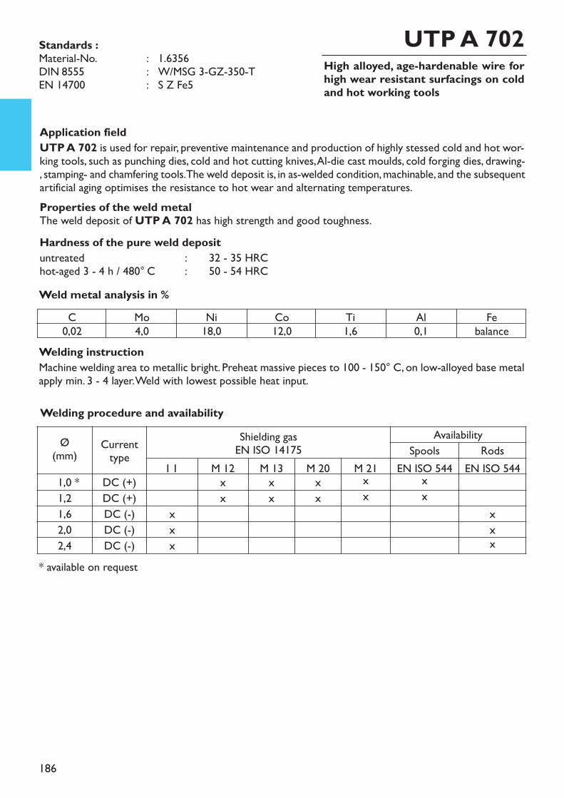
186
High alloyed, age-hardenable wire forhigh wear resistant surfacings on coldand hot working tools
Application fieldUTP A 702 is used for repair, preventive maintenance and production of highly stessed cold and hot wor-king tools, such as punching dies, cold and hot cutting knives, Al-die cast moulds, cold forging dies, drawing-, stamping- and chamfering tools. The weld deposit is, in as-welded condition, machinable, and the subsequentartificial aging optimises the resistance to hot wear and alternating temperatures.Properties of the weld metalThe weld deposit of UTP A 702 has high strength and good toughness.Hardness of the pure weld deposituntreated : 32 - 35 HRChot-aged 3 - 4 h / 480° C : 50 - 54 HRCWeld metal analysis in %
UTP A 702
* available on request
Standards :Material-No. : 1.6356DIN 8555 : W/MSG 3-GZ-350-TEN 14700 : S Z Fe5
C0,02
Mo4,0
Ni18,0
Co12,0
Ti1,6
Al0,1
Febalance
Welding instructionMachine welding area to metallic bright. Preheat massive pieces to 100 - 150° C, on low-alloyed base metalapply min. 3 - 4 layer. Weld with lowest possible heat input.
Ø(mm) Current
typeShielding gasEN ISO 14175
AvailabilitySpools Rods
I 1 M 12 M 13 M 20 M 21 EN ISO 544 EN ISO 5441,0 * DC (+) x x x x x1,2 DC (+) x x x x x1,6 DC (-) x x2,0 DC (-) x x2,4 DC (-) x x
Welding procedure and availability
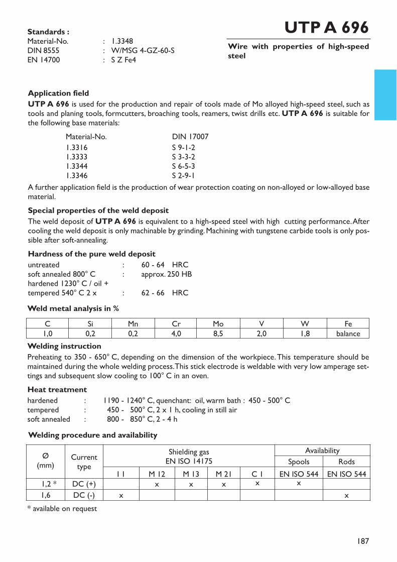
187
Wire with properties of high-speedsteel
Welding instructionPreheating to 350 - 650° C, depending on the dimension of the workpiece. This temperature should bemaintained during the whole welding process. This stick electrode is weldable with very low amperage set-tings and subsequent slow cooling to 100° C in an oven.Heat treatmenthardened : 1190 - 1240° C, quenchant: oil, warm bath : 450 - 500° Ctempered : 1450 - 1500° C, 2 x 1 h, cooling in still airsoft annealed : 1800 - 1850° C, 2 - 4 h
Application fieldUTP A 696 is used for the production and repair of tools made of Mo alloyed high-speed steel, such astools and planing tools, formcutters, broaching tools, reamers, twist drills etc. UTP A 696 is suitable forthe following base materials:
Material-No. DIN 170071.3316 S 9-1-21.3333 S 3-3-21.3344 S 6-5-31.3346 S 2-9-1
A further application field is the production of wear protection coating on non-alloyed or low-alloyed basematerial.Special properties of the weld depositThe weld deposit of UTP A 696 is equivalent to a high-speed steel with high cutting performance. Aftercooling the weld deposit is only machinable by grinding. Machining with tungstene carbide tools is only pos-sible after soft-annealing. Hardness of the pure weld deposituntreated : 60 - 64 HRCsoft annealed 800° C : approx. 250 HBhardened 1230° C / oil +tempered 540° C 2 x : 62 - 66 HRCWeld metal analysis in %
UTP A 696
* available on request
Standards :Material-No. : 1.3348DIN 8555 : W/MSG 4-GZ-60-SEN 14700 : S Z Fe4
C1,0
Si0,2
Mn0,2
Cr4,0
Mo8,5
V2,0
W1,8
Febalance
Ø(mm) Current
typeShielding gasEN ISO 14175
AvailabilitySpools Rods
I 1 M 12 M 13 M 21 C 1 EN ISO 544 EN ISO 5441,2 * DC (+) x x x x x1,6 DC (-) x x
Welding procedure and availability

188
Wire for wear and corrosion resistantsurfacings
Welding instructionUTP A 661Welding with MIG pulsed current provides a low-in-spatter deposit of perfect appearance. Thepreheating must be matched to the parent metal and the welding scope, generally between 150° C - 400°C. Slow cooling in still air or under a cover resp. in an oven. Tempering, if necessary.
Application fieldUTP A 661 is used for wear resistant claddings on construction parts made of non-alloyed or low-alloyedsteels and cast steels, hot working steels, high alloyed steels and cast steels, particularly for one-layer-welding. Special application fields are claddings on machine parts made of high tensile steel for hardeningand tempering, hot working tools, continuous casting rolls and dummy blocks, membrane sides in coal bur-ning power stations and parts resistant against high temperature up to 900° C.Special properties of the weld depositThe martensitic weld deposit is wear resistant also at elevated temperatures. It is resistant against water,seawater, steam and diluted organic acids. High thermal strength.Hardness of the pure weld deposituntreated : approx. 40 HRCone-layer-welding on C 45 : approx. 55 HRCWeld metal analysis in %
UTP A 661
* available on request
Standards :Material-No. : 1.4115EN ISO 14343-A : W/G Z 17 Mo HEN 14700 : S Fe7
C0,22
Si0,7
Mn0,7
Cr17,5
Mo1,2
Febalance
ApprovalsTÜV (No. 06743-GMAW)
Ø(mm) Current
typeShielding gasEN ISO 14175
AvailabilitySpools Rods
I 1 M 12 M 13 M 21 C 1 EN ISO 544 EN ISO 5441,0 * DC (+) x x x x x1,2 DC (+) x x x x x1,6 DC (+) x x x x x2,4 DC (-) x x
Welding procedure and availability
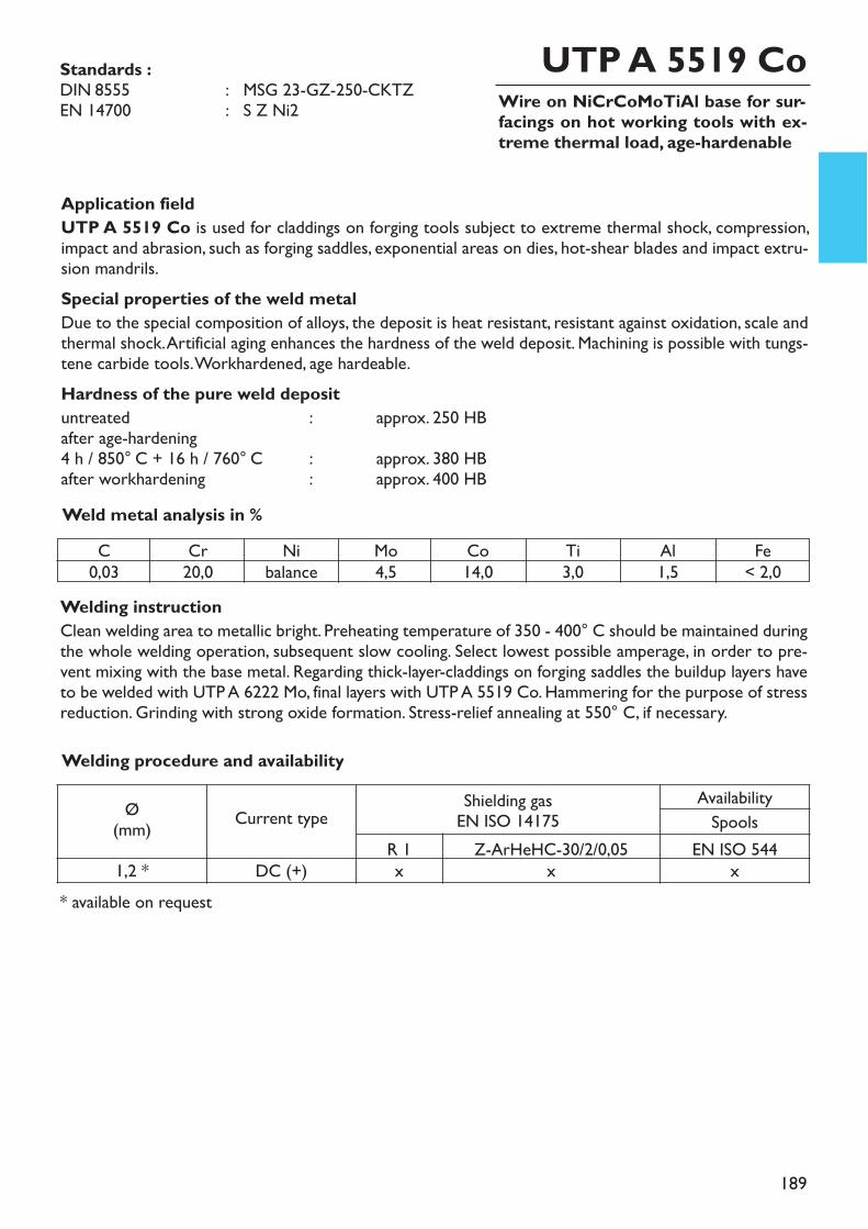
189
Wire on NiCrCoMoTiAl base for sur-facings on hot working tools with ex-treme thermal load, age-hardenable
Application fieldUTP A 5519 Co is used for claddings on forging tools subject to extreme thermal shock, compression,impact and abrasion, such as forging saddles, exponential areas on dies, hot-shear blades and impact extru-sion mandrils.Special properties of the weld metalDue to the special composition of alloys, the deposit is heat resistant, resistant against oxidation, scale andthermal shock. Artificial aging enhances the hardness of the weld deposit. Machining is possible with tungs-tene carbide tools. Workhardened, age hardeable.Hardness of the pure weld deposituntreated : approx. 250 HBafter age-hardening4 h / 850° C + 16 h / 760° C : approx. 380 HBafter workhardening : approx. 400 HB
Welding instructionClean welding area to metallic bright. Preheating temperature of 350 - 400° C should be maintained duringthe whole welding operation, subsequent slow cooling. Select lowest possible amperage, in order to pre-vent mixing with the base metal. Regarding thick-layer-claddings on forging saddles the buildup layers haveto be welded with UTP A 6222 Mo, final layers with UTP A 5519 Co. Hammering for the purpose of stressreduction. Grinding with strong oxide formation. Stress-relief annealing at 550° C, if necessary.
Weld metal analysis in %
UTP A 5519 Co Standards : DIN 8555 : MSG 23-GZ-250-CKTZEN 14700 : S Z Ni2
C0,03
Cr20,0
Nibalance
Mo4,5
Co14,0
Ti3,0
Al1,5
Fe< 2,0
* available on request
Welding procedure and availability
Ø(mm) Current type Shielding gas
EN ISO 14175AvailabilitySpools
R 1 Z-ArHeHC-30/2/0,05 EN ISO 5441,2 * DC (+) x x x
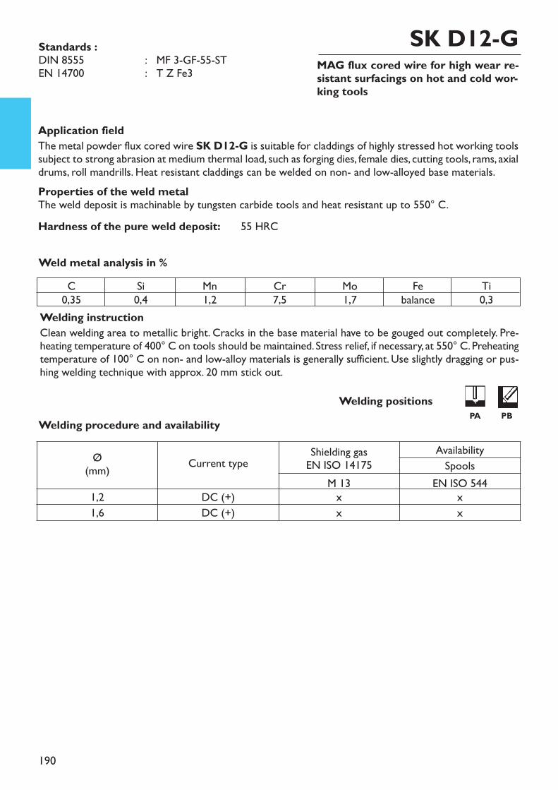
190
MAG flux cored wire for high wear re-sistant surfacings on hot and cold wor-king tools
Application fieldThe metal powder flux cored wire SK D12-G is suitable for claddings of highly stressed hot working toolssubject to strong abrasion at medium thermal load, such as forging dies, female dies, cutting tools, rams, axialdrums, roll mandrills. Heat resistant claddings can be welded on non- and low-alloyed base materials. Properties of the weld metalThe weld deposit is machinable by tungsten carbide tools and heat resistant up to 550° C.Hardness of the pure weld deposit: 55 HRC
Welding instructionClean welding area to metallic bright. Cracks in the base material have to be gouged out completely. Pre-heating temperature of 400° C on tools should be maintained. Stress relief, if necessary, at 550° C. Preheatingtemperature of 100° C on non- and low-alloy materials is generally sufficient. Use slightly dragging or pus-hing welding technique with approx. 20 mm stick out.
Weld metal analysis in %
Standards :DIN 8555 : MF 3-GF-55-STEN 14700 : T Z Fe3
Welding procedure and availability
SK D12-G
Welding positionsPA PB
C0,35
Si0,4
Mn1,2
Cr7,5
Mo1,7
Febalance
Ti0,3
Ø(mm) Current type Shielding gas
EN ISO 14175AvailabilitySpools
M 13 EN ISO 5441,2 DC (+) x x1,6 DC (+) x x
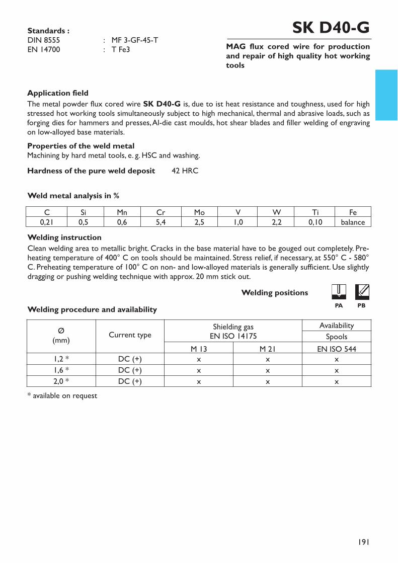
191
MAG flux cored wire for productionand repair of high quality hot workingtools
Application fieldThe metal powder flux cored wire SK D40-G is, due to ist heat resistance and toughness, used for highstressed hot working tools simultaneously subject to high mechanical, thermal and abrasive loads, such asforging dies for hammers and presses, Al-die cast moulds, hot shear blades and filler welding of engravingon low-alloyed base materials. Properties of the weld metalMachining by hard metal tools, e. g. HSC and washing.Hardness of the pure weld deposit 42 HRC
Welding instructionClean welding area to metallic bright. Cracks in the base material have to be gouged out completely. Pre-heating temperature of 400° C on tools should be maintained. Stress relief, if necessary, at 550° C - 580°C. Preheating temperature of 100° C on non- and low-alloyed materials is generally sufficient. Use slightlydragging or pushing welding technique with approx. 20 mm stick out.
Weld metal analysis in %
* available on request
SK D40-GStandards :DIN 8555 : MF 3-GF-45-TEN 14700 : T Fe3
Welding procedure and availabilityWelding positions
PA PB
C0,21
Si0,5
Mn0,6
Cr5,4
Mo2,5
W2,2
Ti0,10
Febalance
V1,0
Ø(mm) Current type Shielding gas
EN ISO 14175AvailabilitySpools
M 13 M 21 EN ISO 5441,2 * DC (+) x x x1,6 * DC (+) x x x2,0 * DC (+) x x x
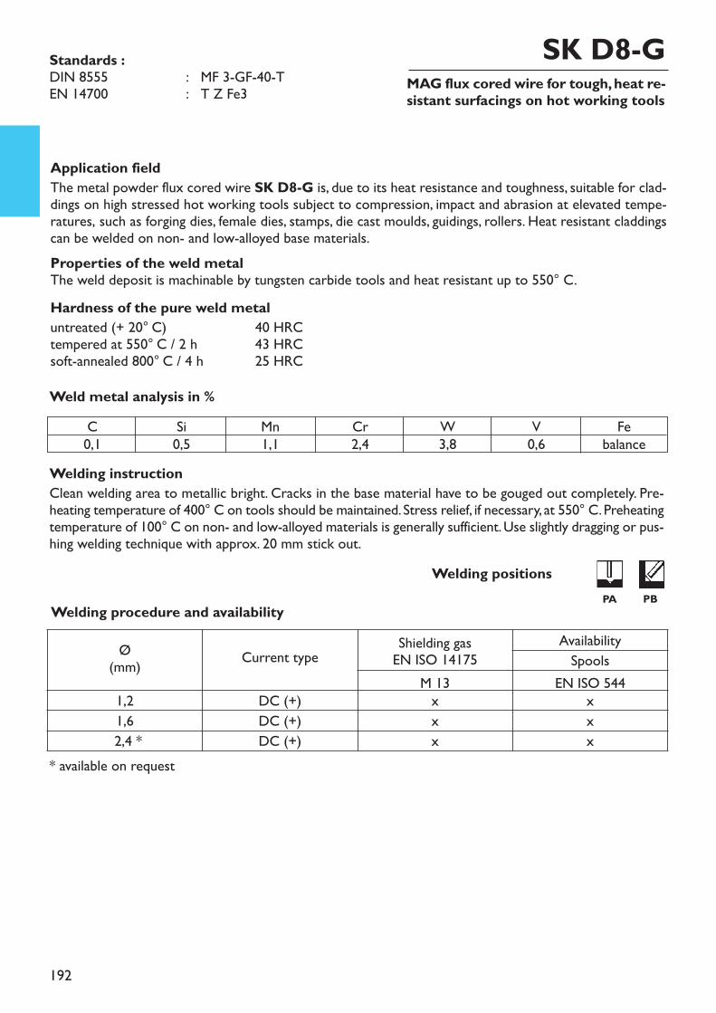
192
MAG flux cored wire for tough, heat re-sistant surfacings on hot working tools
Application fieldThe metal powder flux cored wire SK D8-G is, due to its heat resistance and toughness, suitable for clad-dings on high stressed hot working tools subject to compression, impact and abrasion at elevated tempe-ratures, such as forging dies, female dies, stamps, die cast moulds, guidings, rollers. Heat resistant claddingscan be welded on non- and low-alloyed base materials. Properties of the weld metalThe weld deposit is machinable by tungsten carbide tools and heat resistant up to 550° C.Hardness of the pure weld metaluntreated (+ 20° C) 40 HRCtempered at 550° C / 2 h 43 HRCsoft-annealed 800° C / 4 h 25 HRC
Welding instructionClean welding area to metallic bright. Cracks in the base material have to be gouged out completely. Pre-heating temperature of 400° C on tools should be maintained. Stress relief, if necessary, at 550° C. Preheatingtemperature of 100° C on non- and low-alloyed materials is generally sufficient. Use slightly dragging or pus-hing welding technique with approx. 20 mm stick out.
Weld metal analysis in %
Standards :DIN 8555 : MF 3-GF-40-TEN 14700 : T Z Fe3
SK D8-G
Welding procedure and availability
* available on request
Welding positions PA PB
C0,1
Si0,5
Mn1,1
Cr2,4
W3,8
V0,6
Febalance
Ø(mm) Current type Shielding gas
EN ISO 14175AvailabilitySpools
M 13 EN ISO 5441,2 DC (+) x x1,6 DC (+) x x2,4 * DC (+) x x

193
MAG flux cored wire for heat resistant surfa-cings on hot working tools
* available on request
Application fieldThe metal powder flux cored wire SK D15-G is used for high stressed hot working tools, which are si-multaneously subject to abrasion, compression and impact. Main application fields are axial rolls, roll man-drills, hot shear blades. The elevated temperature hardness (up to 550° C) and the abrasion resistance arereached by addition of tungsten, molybdenum, chromium, cobalt and vanadium. SK D15-G is suitable forthe production and for the repair of high quality hot working tools.Properties of the weld metalThe weld deposit of SK D15-G has a martensitic structure and may be machined by grinding.Hardness of the pure weld deposit 60 HRC
Welding instructionClean welding area to metallic bright. Preheating temperature of 400° C on tools should be maintained. Slowcooling in an oven or under a cover, tempering at 550° C, if necessary. Use neutral or slight pushing wel-ding technique. Pulsed arc improves weldability.
Weld metal analysis in %
SK D15-GStandards : DIN 8555 : MF 3-GF-55-STEN 14700 : T Fe3
Welding procedure and availabilityWelding positions
PA PB
C0,4
Si0,4
Mn0,6
Cr1,4
Mo0,5
V0,4
W9,0
Co3,0
Febalance
Ø(mm) Current type Shielding gas
EN ISO 14175AvailabilitySpools
M 13 EN ISO 5441,2 * DC (+) x x1,6 DC (+) x x
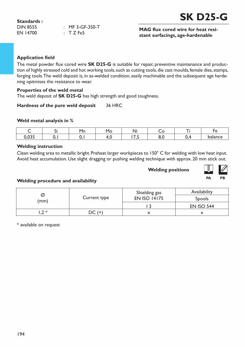
194
MAG flux cored wire for heat resi-stant surfacings, age-hardenable
Welding instructionClean welding area to metallic bright. Preheat larger workpieces to 150° C for welding with low heat input.Avoid heat accumulation. Use slight dragging or pushing welding technique with approx. 20 mm stick out.
* available on request
Weld metal analysis in %
Application fieldThe metal powder flux cored wire SK D25-G is suitable for repair, preventive maintenance and produc-tion of highly stressed cold and hot working tools, such as cutting tools, die cast moulds, female dies, stamps,forging tools. The weld deposit is, in as-welded condition, easily machinable and the subsequent age harde-ning opitmises the resistance to wear.Properties of the weld metalThe weld deposit of SK D25-G has high strength and good toughness.Hardness of the pure weld deposit 36 HRC
SK D25-GStandards :DIN 8555 : MF 3-GF-350-TEN 14700 : T Z Fe5
Welding procedure and availabilityWelding positions
PA PB
C0,035
Si0,1
Mn0,1
Mo4,0
Ni17,5
Co8,0
Ti0,4
Febalance
Ø(mm) Current type Shielding gas
EN ISO 14175AvailabilitySpools
I 3 EN ISO 5441,2 * DC (+) x x
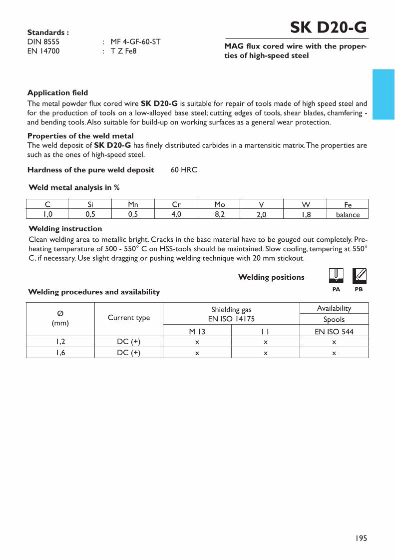
195
MAG flux cored wire with the proper-ties of high-speed steel
Welding instructionClean welding area to metallic bright. Cracks in the base material have to be gouged out completely. Pre-heating temperature of 500 - 550° C on HSS-tools should be maintained. Slow cooling, tempering at 550°C, if necessary. Use slight dragging or pushing welding technique with 20 mm stickout.
Weld metal analysis in %
Application fieldThe metal powder flux cored wire SK D20-G is suitable for repair of tools made of high speed steel andfor the production of tools on a low-alloyed base steel; cutting edges of tools, shear blades, chamfering -and bending tools. Also suitable for build-up on working surfaces as a general wear protection.Properties of the weld metalThe weld deposit of SK D20-G has finely distributed carbides in a martensitic matrix. The properties aresuch as the ones of high-speed steel.Hardness of the pure weld deposit 60 HRC
SK D20-GStandards :DIN 8555 : MF 4-GF-60-STEN 14700 : T Z Fe8
Welding procedures and availabilityWelding positions
PA PB
C1,0
Si0,5
Mn0,5
Cr4,0
Mo8,2
V2,0
W1,8
Febalance
Ø(mm) Current type Shielding gas
EN ISO 14175AvailabilitySpools
M 13 I 1 EN ISO 5441,2 DC (+) x x x1,6 DC (+) x x x
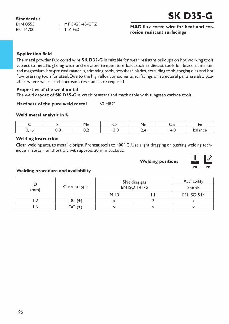
196
MAG flux cored wire for heat and cor-rosion resistant surfacings
Welding instructionClean welding area to metallic bright. Preheat tools to 400° C. Use slight dragging or pushing welding tech-nique in spray - or short arc with approx. 20 mm stickout.
Weld metal analysis in %
Application fieldThe metal powder flux cored wire SK D35-G is suitable for wear resistant buildups on hot working toolssubject to metallic gliding wear and elevated temperature load, such as diecast tools for brass, aluminiumand magnesium, hot-pressed mandrils, trimming tools, hot-shear blades, extruding tools, forging dies and hotflow pressing tools for steel. Due to the high alloy components, surfacings on structural parts are also pos-sible, where wear - and corrosion resistance are required.Properties of the weld metalThe weld deposit of SK D35-G is crack resistant and machinable with tungsten carbide tools.Hardness of the pure weld metal 50 HRC
SK D35-GStandards :DIN 8555 : MF 5-GF-45-CTZEN 14700 : T Z Fe3
Welding procedure and availabilityWelding positions
PA PB
C0,16
Si0,8
Mn0,2
Cr13,0
Mo2,4
Co14,0
Febalance
Ø(mm) Current type Shielding gas
EN ISO 14175AvailabilitySpools
M 13 I 1 EN ISO 5441,2 DC (+) x x x1,6 DC (+) x x x
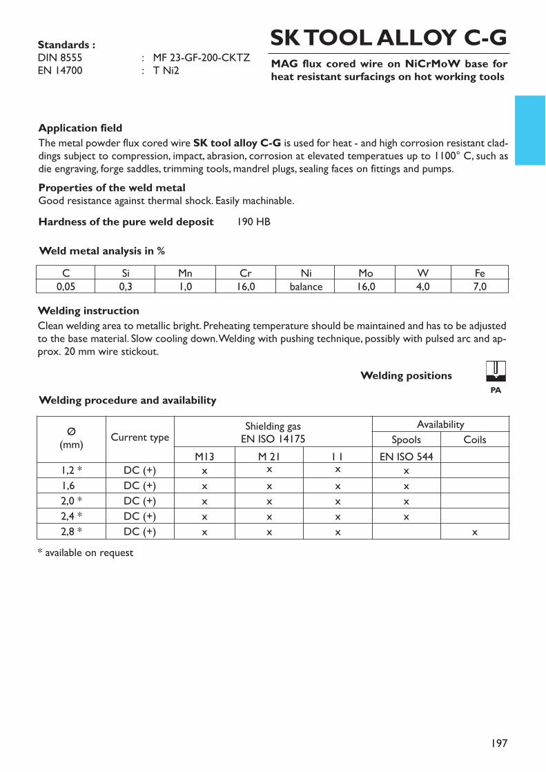
197
MAG flux cored wire on NiCrMoW base forheat resistant surfacings on hot working tools
Welding instructionClean welding area to metallic bright. Preheating temperature should be maintained and has to be adjustedto the base material. Slow cooling down. Welding with pushing technique, possibly with pulsed arc and ap-prox. 20 mm wire stickout.
Weld metal analysis in %
Application fieldThe metal powder flux cored wire SK tool alloy C-G is used for heat - and high corrosion resistant clad-dings subject to compression, impact, abrasion, corrosion at elevated temperatues up to 1100° C, such asdie engraving, forge saddles, trimming tools, mandrel plugs, sealing faces on fittings and pumps.Properties of the weld metalGood resistance against thermal shock. Easily machinable.Hardness of the pure weld deposit 190 HB
SK TOOL ALLOY C-GStandards :DIN 8555 : MF 23-GF-200-CKTZEN 14700 : T Ni2
Welding procedure and availabilityWelding positions
PA
C0,05
Si0,3
Mn1,0
Cr16,0
Nibalance
Mo16,0
W4,0
Fe7,0
Ø(mm) Current type Shielding gas
EN ISO 14175Availability
Spools CoilsM13 M 21 I 1 EN ISO 544
1,2 * DC (+) x x x x1,6 DC (+) x x x x2,0 * DC (+) x x x x2,4 * DC (+) x x x x2,8 * DC (+) x x x x
* available on request
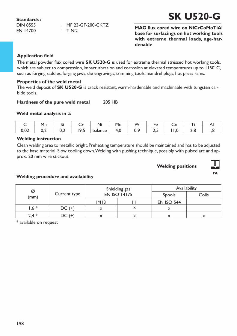
198
MAG flux cored wire on NiCrCoMoTiAlbase for surfacings on hot working toolswith extreme thermal loads, age-har-denable
Welding instructionClean welding area to metallic bright. Preheating temperature should be maintained and has to be adjustedto the base material. Slow cooling down. Welding with pushing technique, possibly with pulsed arc and ap-prox. 20 mm wire stickout.
Weld metal analysis in %
Application fieldThe metal powder flux cored wire SK U520-G is used for extreme thermal stressed hot working tools,which are subject to compression, impact, abrasion and corrosion at elevated temperatures up to 1150°C,such as forging saddles, forging jaws, die engravings, trimming tools, mandrel plugs, hot press rams.Properties of the weld metalThe weld deposit of SK U520-G is crack resistant, warm-hardenable and machinable with tungsten car-bide tools.Hardness of the pure weld metal 205 HB
SK U520-GStandards :DIN 8555 : MF 23-GF-200-CKTZEN 14700 : T Ni2
Welding procedure and availabilityWelding positions
PA
C Mn Si Cr Ni Mo W Fe Co Ti Al0,02 0,2 0,2 19,5 balance 4,0 0,9 2,5 11,0 2,8 1,8
Ø(mm) Current type Shielding gas
EN ISO 14175Availability
Spools CoilsIM13 I 1 EN ISO 544
1,6 * DC (+) x x x2,4 * DC (+) x x x x
* available on request
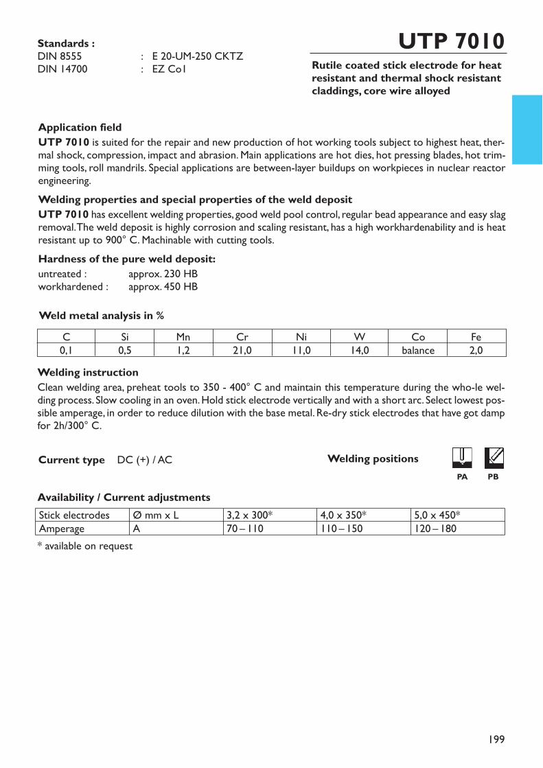
199
Rutile coated stick electrode for heatresistant and thermal shock resistantcladdings, core wire alloyed
UTP 7010
Welding instructionClean welding area, preheat tools to 350 - 400° C and maintain this temperature during the who-le wel-ding process. Slow cooling in an oven. Hold stick electrode vertically and with a short arc. Select lowest pos-sible amperage, in order to reduce dilution with the base metal. Re-dry stick electrodes that have got dampfor 2h/300° C.
Availability / Current adjustments
Current type DC (+) / AC
Application fieldUTP 7010 is suited for the repair and new production of hot working tools subject to highest heat, ther-mal shock, compression, impact and abrasion. Main applications are hot dies, hot pressing blades, hot trim-ming tools, roll mandrils. Special applications are between-layer buildups on workpieces in nuclear reactorengineering.Welding properties and special properties of the weld depositUTP 7010 has excellent welding properties, good weld pool control, regular bead appearance and easy slagremoval. The weld deposit is highly corrosion and scaling resistant, has a high workhardenability and is heatresistant up to 900° C. Machinable with cutting tools.Hardness of the pure weld deposit:untreated : approx. 230 HBworkhardened : approx. 450 HBWeld metal analysis in %
* available on request
Standards :DIN 8555 : E 20-UM-250 CKTZDIN 14700 : EZ Co1
C0,1
Si0,5
Mn1,2
Cr21,0
Ni11,0
W14,0
Cobalance
Fe2,0
Stick electrodesAmperage
Ø mm x LA
3,2 x 300*70 – 110
4,0 x 350*110 – 150
5,0 x 450*120 – 180
Welding positionsPA PB
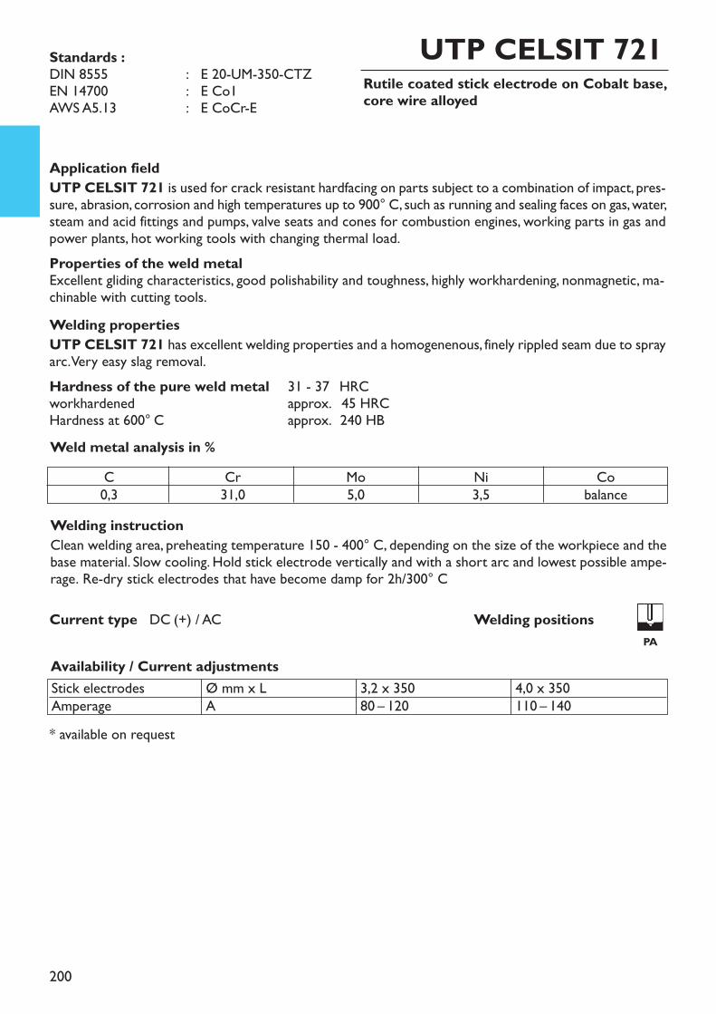
200
Rutile coated stick electrode on Cobalt base,core wire alloyed
UTP CELSIT 721
Application fieldUTP CELSIT 721 is used for crack resistant hardfacing on parts subject to a combination of impact, pres-sure, abrasion, corrosion and high temperatures up to 900° C, such as running and sealing faces on gas, water,steam and acid fittings and pumps, valve seats and cones for combustion engines, working parts in gas andpower plants, hot working tools with changing thermal load. Properties of the weld metalExcellent gliding characteristics, good polishability and toughness, highly workhardening, nonmagnetic, ma-chinable with cutting tools.Welding propertiesUTP CELSIT 721 has excellent welding properties and a homogenenous, finely rippled seam due to sprayarc. Very easy slag removal.Hardness of the pure weld metal 31 - 37 HRCworkhardened approx. 245 HRCHardness at 600° C approx. 240 HB
Welding instructionClean welding area, preheating temperature 150 - 400° C, depending on the size of the workpiece and thebase material. Slow cooling. Hold stick electrode vertically and with a short arc and lowest possible ampe-rage. Re-dry stick electrodes that have become damp for 2h/300° C
Availability / Current adjustments
Current type DC (+) / AC
Weld metal analysis in %
* available on request
C0,3
Cr31,0
Mo5,0
Ni3,5
Cobalance
Stick electrodesAmperage
Ø mm x LA
3,2 x 35080 – 120
4,0 x 350110 – 140
Standards : DIN 8555 : E 20-UM-350-CTZEN 14700 : E Co1AWS A5.13 : E CoCr-E
Welding positionsPA
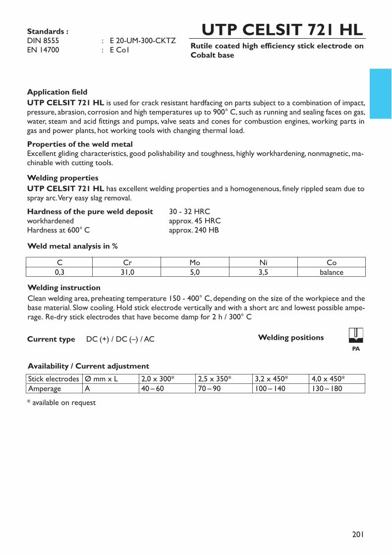
201
Rutile coated high efficiency stick electrode onCobalt base
UTP CELSIT 721 HL
Application fieldUTP CELSIT 721 HL is used for crack resistant hardfacing on parts subject to a combination of impact,pressure, abrasion, corrosion and high temperatures up to 900° C, such as running and sealing faces on gas,water, steam and acid fittings and pumps, valve seats and cones for combustion engines, working parts ingas and power plants, hot working tools with changing thermal load. Properties of the weld metalExcellent gliding characteristics, good polishability and toughness, highly workhardening, nonmagnetic, ma-chinable with cutting tools.Welding propertiesUTP CELSIT 721 HL has excellent welding properties and a homogenenous, finely rippled seam due tospray arc. Very easy slag removal.Hardness of the pure weld deposit 30 - 32 HRCworkhardened approx. 45 HRCHardness at 600° C approx. 240 HB
Welding instructionClean welding area, preheating temperature 150 - 400° C, depending on the size of the workpiece and thebase material. Slow cooling. Hold stick electrode vertically and with a short arc and lowest possible ampe-rage. Re-dry stick electrodes that have become damp for 2 h / 300° C
Availability / Current adjustment
Current type DC (+) / DC (–) / AC
Weld metal analysis in %
* available on request
Standards :DIN 8555 : E 20-UM-300-CKTZEN 14700 : E Co1
C0,3
Cr31,0
Mo5,0
Ni3,5
Cobalance
Stick electrodesAmperage
Ø mm x LA
2,0 x 300*40 – 60
2,5 x 350*70 – 90
3,2 x 450*100 – 140
4,0 x 450*130 – 180
Welding positionsPA

202
Rutile coated stick electrode on Cobalt base,core wire alloyed
UTP CELSIT 706
Application fieldUTP CELSIT 706 is used for hardfacing on parts subject to a combination of erosion, corrosion, cavita-tion, impact, pressure, abrasion and high temperatures up to 900° C, such as tight surfaces on fittings, valveseats and cones for combustion engines, gliding surfaces metal-metal, highly stressed hot working tools wit-hout thermal shock, milling mixers and drilling tools. Properties of the weld metalExcellent gliding characteristics, easy polishability, good toughness, nonmagnetic. Machining by grinding orwith tungsten carbide cutting tools.Welding propertiesUTP CELSIT 706 has excellent welding properties and a homogenenous, finely rippled seam due to sprayarc. Very easy slag removal.Hardness of the pure weld deposit 40 - 42 HRCHardness at 500°C approx. 30 HRCHardness at 700°C approx. 160 HB
Welding instructionClean welding area, preheating temperature 450 –600° C, very slow cooling. Hold stick electrode verticallyand with a short arc and lowest possible amperage. Re-dry stick electrodes that have become damp for 2h / 300°C.
Availability / Current adjustment
Current type DC (+) / AC
Weld metal analysis in %
* available on request
C1,1
Cr27,5
W4,5
Cobalance
Stick electrodesAmperage
Ø mm x LA
3,2 x 35070 – 110
4,0 x 35090 – 130
5,0 x 350*110 – 150
Standards : DIN 8555 : E 20-UM-40-CSTZEN 14700 : E Z Co2AWS A5.13 : E CoCr-A
Welding positionsPA
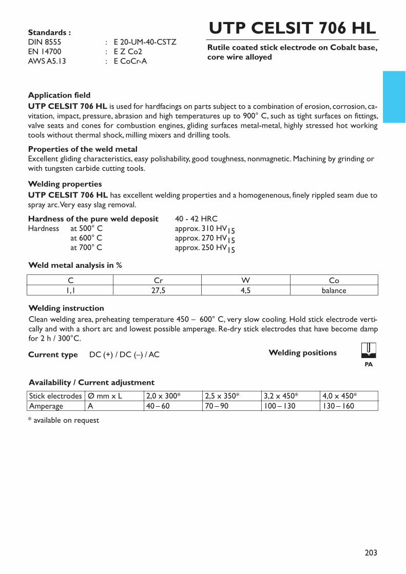
203
Rutile coated stick electrode on Cobalt base,core wire alloyed
UTP CELSIT 706 HL
Application fieldUTP CELSIT 706 HL is used for hardfacings on parts subject to a combination of erosion, corrosion, ca-vitation, impact, pressure, abrasion and high temperatures up to 900° C, such as tight surfaces on fittings,valve seats and cones for combustion engines, gliding surfaces metal-metal, highly stressed hot workingtools without thermal shock, milling mixers and drilling tools. Properties of the weld metalExcellent gliding characteristics, easy polishability, good toughness, nonmagnetic. Machining by grinding orwith tungsten carbide cutting tools.Welding propertiesUTP CELSIT 706 HL has excellent welding properties and a homogenenous, finely rippled seam due tospray arc. Very easy slag removal.Hardness of the pure weld deposit 40 - 42 HRCHardness at 500° C approx. 310 HV15at 600° C approx. 270 HV15at 700° C approx. 250 HV15
Welding instructionClean welding area, preheating temperature 450 – 600° C, very slow cooling. Hold stick electrode verti-cally and with a short arc and lowest possible amperage. Re-dry stick electrodes that have become dampfor 2 h / 300°C.
Availability / Current adjustment
Current type DC (+) / DC (–) / AC
Weld metal analysis in %
* available on request
Standards :DIN 8555 : E 20-UM-40-CSTZEN 14700 : E Z Co2AWS A5.13 : E CoCr-A
C1,1
Cr27,5
W4,5
Cobalance
Stick electrodesAmperage
Ø mm x LA
2,0 x 300*40 – 60
2,5 x 350*70 – 90
3,2 x 450*100 – 130
4,0 x 450*130 – 160
Welding positionsPA
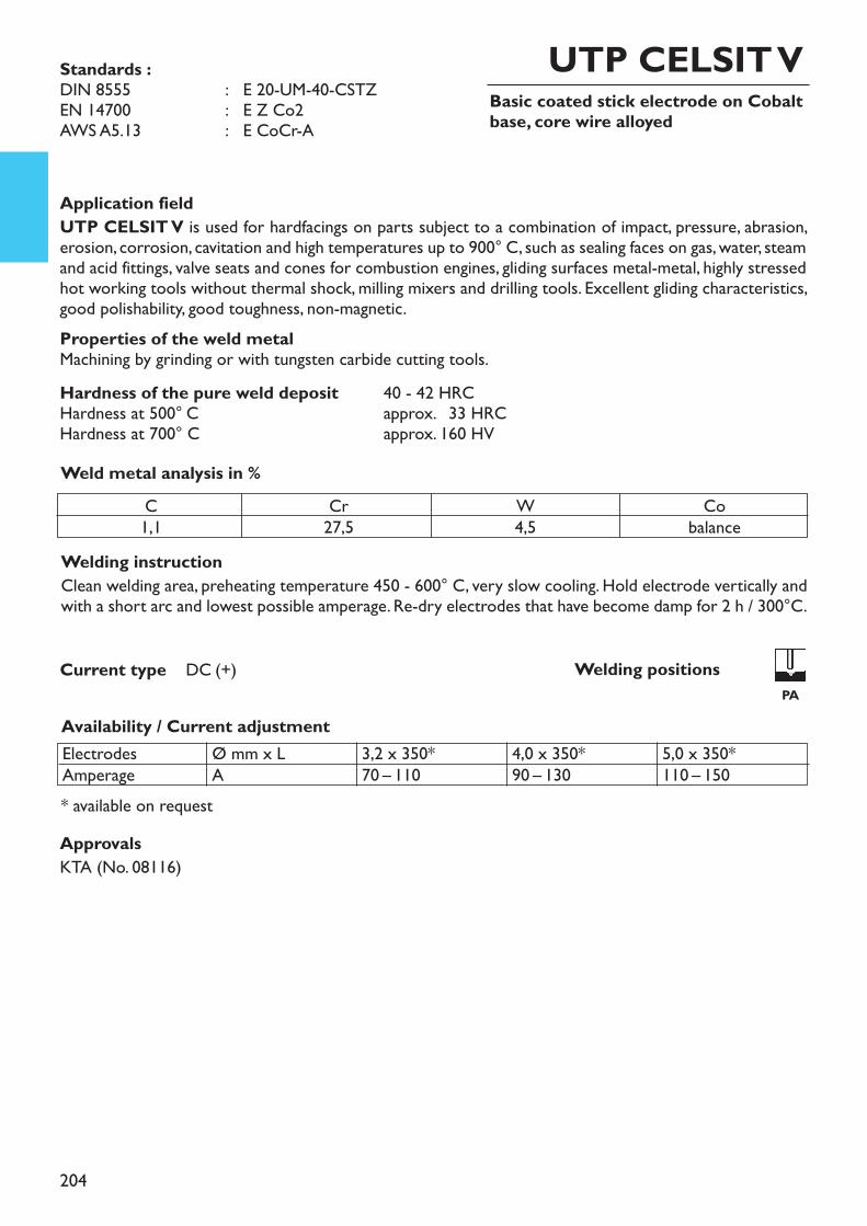
204
Basic coated stick electrode on Cobaltbase, core wire alloyed
UTP CELSIT V
Application fieldUTP CELSIT V is used for hardfacings on parts subject to a combination of impact, pressure, abrasion,erosion, corrosion, cavitation and high temperatures up to 900° C, such as sealing faces on gas, water, steamand acid fittings, valve seats and cones for combustion engines, gliding surfaces metal-metal, highly stressedhot working tools without thermal shock, milling mixers and drilling tools. Excellent gliding characteristics,good polishability, good toughness, non-magnetic. Properties of the weld metalMachining by grinding or with tungsten carbide cutting tools.Hardness of the pure weld deposit 40 - 42 HRCHardness at 500° C approx. 233 HRCHardness at 700° C approx. 160 HV
Welding instructionClean welding area, preheating temperature 450 - 600° C, very slow cooling. Hold electrode vertically andwith a short arc and lowest possible amperage. Re-dry electrodes that have become damp for 2 h / 300°C.
Availability / Current adjustment
Current type DC (+)
Weld metal analysis in %
* available on request
Standards : DIN 8555 : E 20-UM-40-CSTZEN 14700 : E Z Co2AWS A5.13 : E CoCr-A
ElectrodesAmperage
Ø mm x LA
3,2 x 350*70 – 110
4,0 x 350*90 – 130
5,0 x 350*110 – 150
C1,1
Cr27,5
W4,5
Cobalance
ApprovalsKTA (No. 08116)
Welding positionsPA
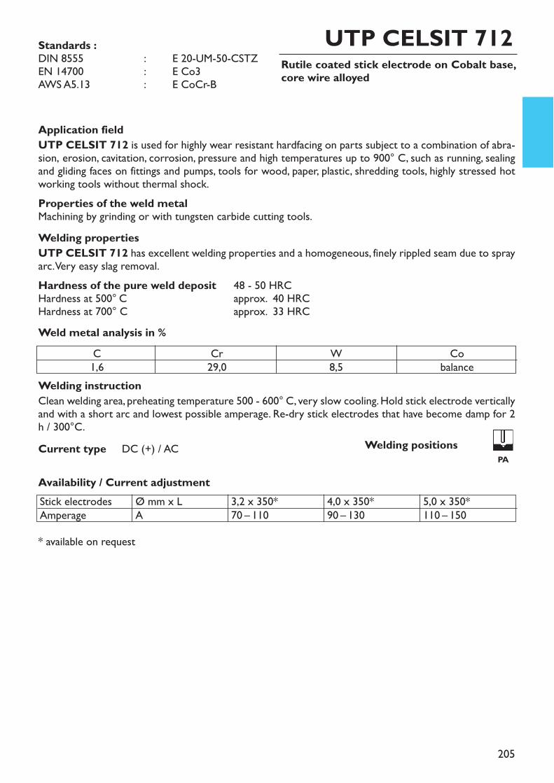
205
Rutile coated stick electrode on Cobalt base,core wire alloyed
UTP CELSIT 712
Application fieldUTP CELSIT 712 is used for highly wear resistant hardfacing on parts subject to a combination of abra-sion, erosion, cavitation, corrosion, pressure and high temperatures up to 900° C, such as running, sealingand gliding faces on fittings and pumps, tools for wood, paper, plastic, shredding tools, highly stressed hotworking tools without thermal shock.Properties of the weld metalMachining by grinding or with tungsten carbide cutting tools.Welding propertiesUTP CELSIT 712 has excellent welding properties and a homogeneous, finely rippled seam due to sprayarc. Very easy slag removal. Hardness of the pure weld deposit 48 - 50 HRCHardness at 500° C approx. 40 HRCHardness at 700° C approx. 33 HRC
Welding instructionClean welding area, preheating temperature 500 - 600° C, very slow cooling. Hold stick electrode verticallyand with a short arc and lowest possible amperage. Re-dry stick electrodes that have become damp for 2h / 300°C.
Availability / Current adjustment
Current type DC (+) / AC
Weld metal analysis in %
* available on request
Standards : DIN 8555 : E 20-UM-50-CSTZEN 14700 : E Co3AWS A5.13 : E CoCr-B
C1,6
Cr29,0
W8,5
Cobalance
Stick electrodesAmperage
Ø mm x LA
3,2 x 350*70 – 110
4,0 x 350*90 – 130
5,0 x 350*110 – 150
Welding positionsPA
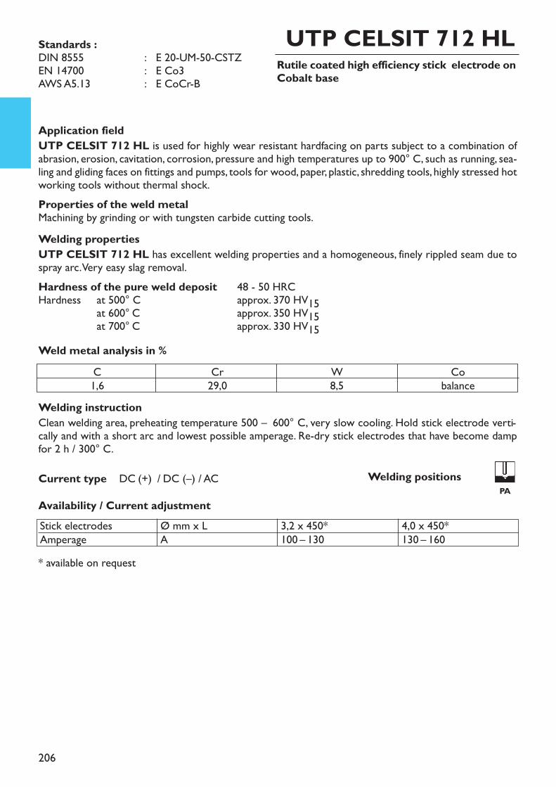
206
Rutile coated high efficiency stick electrode onCobalt base
UTP CELSIT 712 HL
Application fieldUTP CELSIT 712 HL is used for highly wear resistant hardfacing on parts subject to a combination ofabrasion, erosion, cavitation, corrosion, pressure and high temperatures up to 900° C, such as running, sea-ling and gliding faces on fittings and pumps, tools for wood, paper, plastic, shredding tools, highly stressed hotworking tools without thermal shock. Properties of the weld metalMachining by grinding or with tungsten carbide cutting tools.Welding propertiesUTP CELSIT 712 HL has excellent welding properties and a homogeneous, finely rippled seam due tospray arc. Very easy slag removal.Hardness of the pure weld deposit 48 - 50 HRCHardness at 500° C approx. 370 HV15at 600° C approx. 350 HV15at 700° C approx. 330 HV15
Welding instructionClean welding area, preheating temperature 500 – 600° C, very slow cooling. Hold stick electrode verti-cally and with a short arc and lowest possible amperage. Re-dry stick electrodes that have become dampfor 2 h / 300° C.
Availability / Current adjustmentCurrent type DC (+) / DC (–) / AC
Weld metal analysis in %
* available on request
Standards :DIN 8555 : E 20-UM-50-CSTZEN 14700 : E Co3AWS A5.13 : E CoCr-B
C1,6
Cr29,0
W8,5
Cobalance
Stick electrodesAmperage
Ø mm x LA
3,2 x 450*100 – 130
4,0 x 450*130 – 160
Welding positionsPA
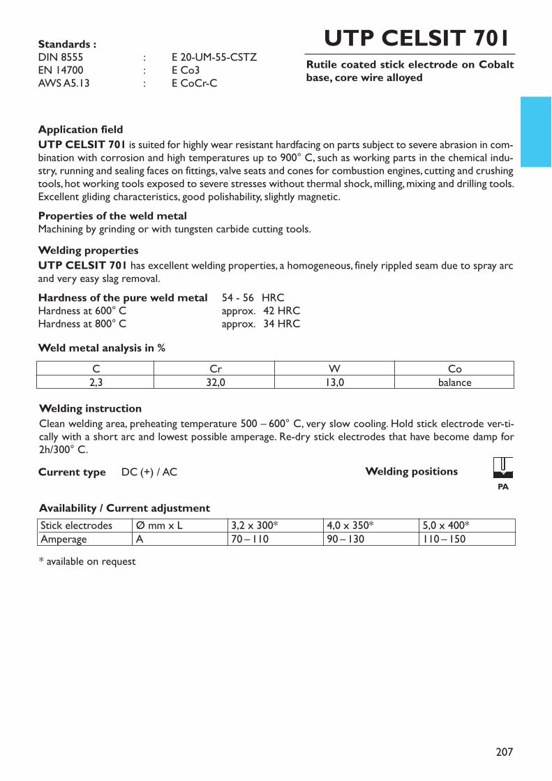
207
Rutile coated stick electrode on Cobaltbase, core wire alloyed
UTP CELSIT 701
Application fieldUTP CELSIT 701 is suited for highly wear resistant hardfacing on parts subject to severe abrasion in com-bination with corrosion and high temperatures up to 900° C, such as working parts in the chemical indu-stry, running and sealing faces on fittings, valve seats and cones for combustion engines, cutting and crushingtools, hot working tools exposed to severe stresses without thermal shock, milling, mixing and drilling tools.Excellent gliding characteristics, good polishability, slightly magnetic. Properties of the weld metalMachining by grinding or with tungsten carbide cutting tools.Welding propertiesUTP CELSIT 701 has excellent welding properties, a homogeneous, finely rippled seam due to spray arcand very easy slag removal.Hardness of the pure weld metal 54 - 56 HRCHardness at 600° C approx. 242 HRCHardness at 800° C approx. 234 HRC
Welding instructionClean welding area, preheating temperature 500 – 600° C, very slow cooling. Hold stick electrode ver-ti-cally with a short arc and lowest possible amperage. Re-dry stick electrodes that have become damp for2h/300° C.
Availability / Current adjustment
Current type DC (+) / AC
Weld metal analysis in %
* available on request
Standards : DIN 8555 : E 20-UM-55-CSTZEN 14700 : E Co3AWS A5.13 : E CoCr-C
C2,3
Cr32,0
W13,0
Cobalance
Stick electrodesAmperage
Ø mm x LA
3,2 x 300*70 – 110
4,0 x 350*90 – 130
5,0 x 400*110 – 150
Welding positionsPA
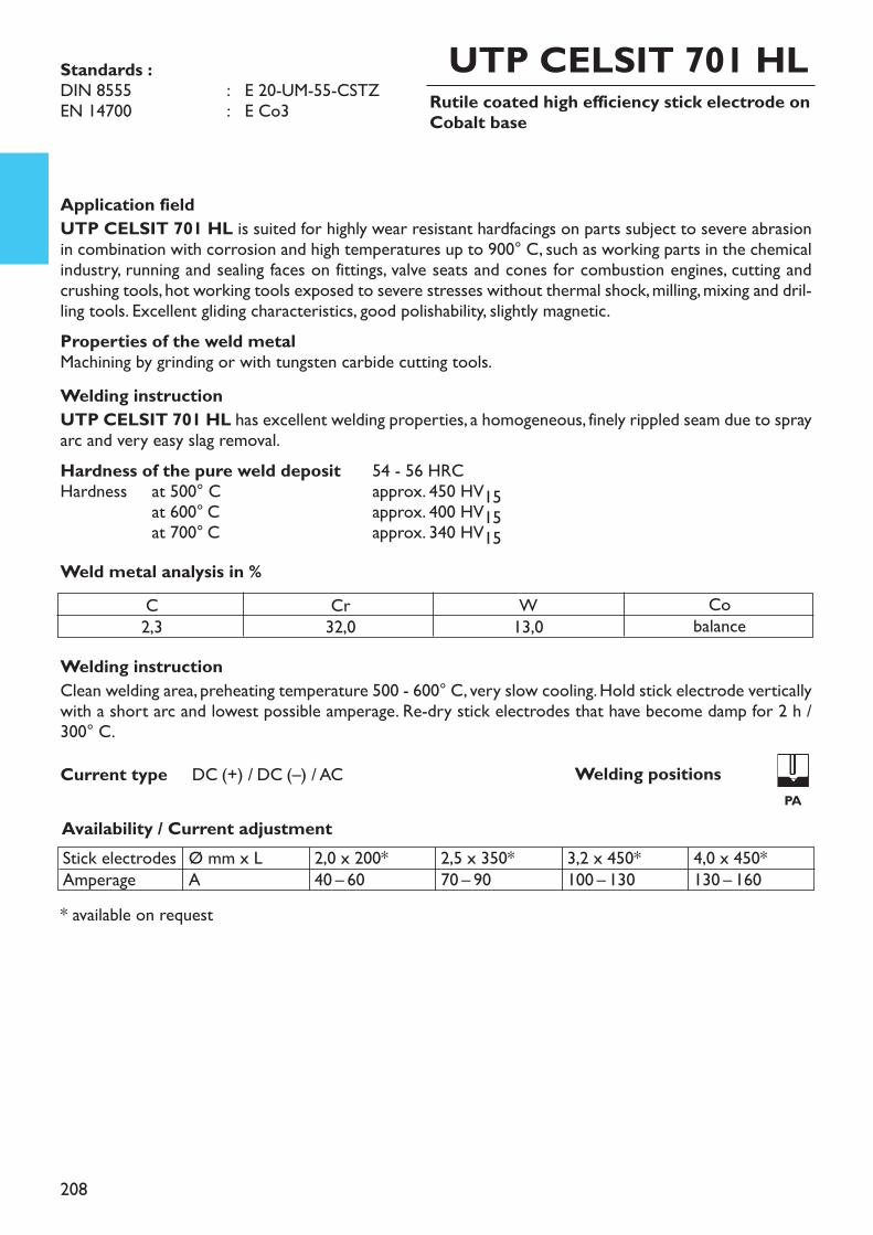
208
Rutile coated high efficiency stick electrode onCobalt base
UTP CELSIT 701 HL
Application fieldUTP CELSIT 701 HL is suited for highly wear resistant hardfacings on parts subject to severe abrasionin combination with corrosion and high temperatures up to 900° C, such as working parts in the chemicalindustry, running and sealing faces on fittings, valve seats and cones for combustion engines, cutting andcrushing tools, hot working tools exposed to severe stresses without thermal shock, milling, mixing and dril-ling tools. Excellent gliding characteristics, good polishability, slightly magnetic. Properties of the weld metalMachining by grinding or with tungsten carbide cutting tools.Welding instructionUTP CELSIT 701 HL has excellent welding properties, a homogeneous, finely rippled seam due to sprayarc and very easy slag removal.Hardness of the pure weld deposit 54 - 56 HRCHardness at 500° C approx. 450 HV15at 600° C approx. 400 HV15at 700° C approx. 340 HV15
Welding instructionClean welding area, preheating temperature 500 - 600° C, very slow cooling. Hold stick electrode verticallywith a short arc and lowest possible amperage. Re-dry stick electrodes that have become damp for 2 h /300° C.
Availability / Current adjustment
Current type DC (+) / DC (–) / AC
Weld metal analysis in %
* available on request
Standards : DIN 8555 : E 20-UM-55-CSTZEN 14700 : E Co3
C2,3
Cr32,0
W13,0
Cobalance
Stick electrodesAmperage
Ø mm x LA
2,0 x 200*40 – 60
2,5 x 350*70 – 90
3,2 x 450*100 – 130
4,0 x 450*130 – 160
Welding positions PA
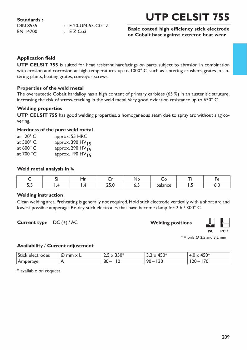
209
Basic coated high efficiency stick electrodeon Cobalt base against extreme heat wear
UTP CELSIT 755
Application fieldUTP CELSIT 755 is suited for heat resistant hardfacings on parts subject to abrasion in combinationwith erosion and corrosion at high temperatures up to 1000° C, such as sintering crushers, grates in sin-tering plants, heating grates, conveyor screws.Properties of the weld metalThe overeutectic Cobalt hardalloy has a high content of primary carbides (65 %) in an austenitic struture,increasing the risk of stress-cracking in the weld metal. Very good oxidation resistance up to 650° C.Welding propertiesUTP CELSIT 755 has good welding properties, a homogeneous seam due to spray arc without slag co-vering.Hardness of the pure weld metalat 520° C approx. 55 HRCat 500° C approx. 390 HV15at 600° C approx. 290 HV15at 700 °C approx. 190 HV15
Welding instructionClean welding area. Preheating is generally not required. Hold stick electrode vertically with a short arc andlowest possible amperage. Re-dry stick electrodes that have become damp for 2 h / 300° C.
* available on request
* = only Ø 2,5 and 3,2 mm
Weld metal analysis in %
Current type DC (+) / AC
Availability / Current adjustment
Standards :DIN 8555 : E 20-UM-55-CGTZEN 14700 : E Z Co3
C5,5
Si1,4
Mn1,4
Cr25,0
Nb6,5
Cobalance
Ti1,5
Fe6,0
Stick electrodesAmperage
Ø mm x LA
2,5 x 350*80 – 110
3,2 x 450*90 – 130
4,0 x 450*120 – 170
Welding positionsPA PC *
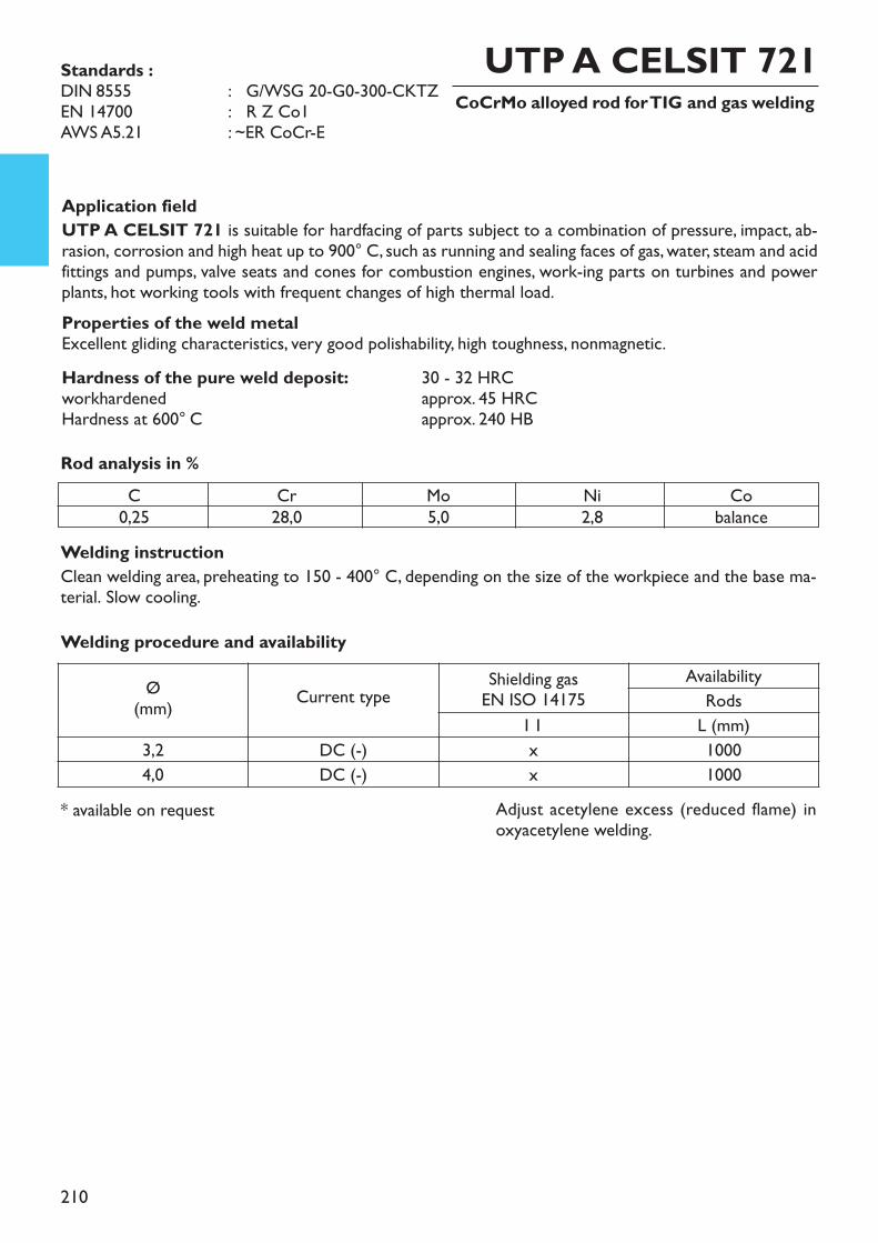
210
CoCrMo alloyed rod for TIG and gas welding
Welding instructionClean welding area, preheating to 150 - 400° C, depending on the size of the workpiece and the base ma-terial. Slow cooling.
Application fieldUTP A CELSIT 721 is suitable for hardfacing of parts subject to a combination of pressure, impact, ab-rasion, corrosion and high heat up to 900° C, such as running and sealing faces of gas, water, steam and acidfittings and pumps, valve seats and cones for combustion engines, work-ing parts on turbines and powerplants, hot working tools with frequent changes of high thermal load. Properties of the weld metalExcellent gliding characteristics, very good polishability, high toughness, nonmagnetic.Hardness of the pure weld deposit: 30 - 32 HRCworkhardened approx. 45 HRCHardness at 600° C approx. 240 HBRod analysis in %
UTP A CELSIT 721
* available on request
Standards :DIN 8555 : G/WSG 20-G0-300-CKTZEN 14700 : R Z Co1AWS A5.21 : ~ER CoCr-E
C0,25
Cr28,0
Mo5,0
Ni2,8
Cobalance
Welding procedure and availability
Ø(mm) Current type Shielding gas
EN ISO 14175Availability
RodsI 1 L (mm)
3,2 DC (-) x 10004,0 DC (-) x 1000
Adjust acetylene excess (reduced flame) inoxyacetylene welding.
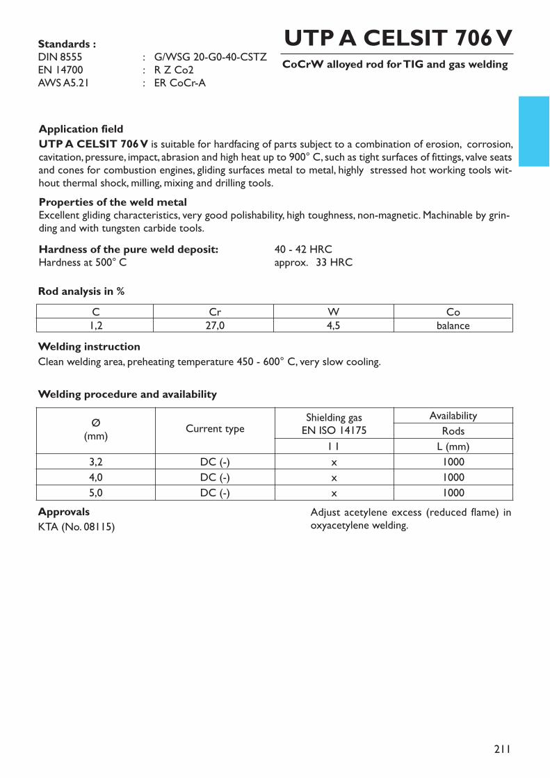
211
CoCrW alloyed rod for TIG and gas welding
Welding instructionClean welding area, preheating temperature 450 - 600° C, very slow cooling.
Application fieldUTP A CELSIT 706 V is suitable for hardfacing of parts subject to a combination of erosion, corrosion,cavitation, pressure, impact, abrasion and high heat up to 900° C, such as tight surfaces of fittings, valve seatsand cones for combustion engines, gliding surfaces metal to metal, highly stressed hot working tools wit-hout thermal shock, milling, mixing and drilling tools. Properties of the weld metalExcellent gliding characteristics, very good polishability, high toughness, non-magnetic. Machinable by grin-ding and with tungsten carbide tools.Hardness of the pure weld deposit: 40 - 42 HRCHardness at 500° C approx. 233 HRCRod analysis in %
UTP A CELSIT 706 VStandards :DIN 8555 : G/WSG 20-G0-40-CSTZEN 14700 : R Z Co2AWS A5.21 : ER CoCr-A
C1,2
Cr27,0
W4,5
Cobalance
ApprovalsKTA (No. 08115)
Adjust acetylene excess (reduced flame) inoxyacetylene welding.
Welding procedure and availability
Ø(mm) Current type Shielding gas
EN ISO 14175Availability
RodsI 1 L (mm)
3,2 DC (-) x 10004,0 DC (-) x 10005,0 DC (-) x 1000
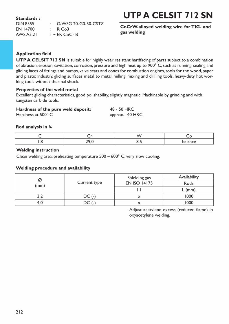
212
CoCrW-alloyed welding wire for TIG- andgas welding
Welding instructionClean welding area, preheating temperature 500 – 600° C, very slow cooling.
Application fieldUTP A CELSIT 712 SN is suitable for highly wear resistant hardfacing of parts subject to a combinationof abrasion, erosion, cavitation, corrosion, pressure and high heat up to 900° C, such as running, sealing andgliding faces of fittings and pumps, valve seats and cones for combustion engines, tools for the wood, paperand plastic industry, gliding surfaces metal to metal, milling, mixing and drilling tools, heavy-duty hot wor-king tools without thermal shock. Properties of the weld metalExcellent gliding characteristics, good polishability, slightly magnetic. Machinable by grinding and withtungsten carbide tools.Hardness of the pure weld deposit: 48 - 50 HRCHardness at 500° C approx. 240 HRCRod analysis in %
UTP A CELSIT 712 SNStandards :DIN 8555 : ~ G/WSG 20-G0-50-CSTZEN 14700 : ~ R Co3AWS A5.21 : ~ ER CoCr-B
C1,8
Cr29,0
W8,5
Cobalance
Adjust acetylene excess (reduced flame) inoxyacetylene welding.
Welding procedure and availability
Ø(mm) Current type Shielding gas
EN ISO 14175Availability
RodsI 1 L (mm)
3,2 DC (-) x 10004,0 DC (-) x 1000
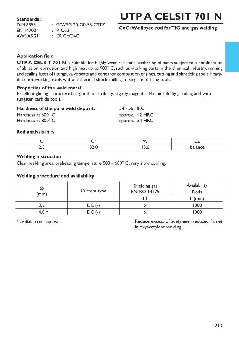
213
CoCrW-alloyed rod for TIG and gas welding
Welding instructionClean welding area, preheating temperature 500 – 600° C, very slow cooling.
Application fieldUTP A CELSIT 701 N is suitable for highly wear resistant hardfacing of parts subject to a combinationof abrasion, corrosion and high heat up to 900° C, such as working parts in the chemical industry, runningand sealing faces of fittings, valve seats and cones for combustion engines, cutting and shredding tools, heavy-duty hot working tools without thermal shock, milling, mixing and drilling tools.Properties of the weld metalExcellent gliding characteristics, good polishability, slightly magnetic. Machinable by grinding and withtungsten carbide tools.Hardness of the pure weld deposit: 54 - 56 HRCHardness at 600° C approx. 242 HRCHardness at 800° C approx. 234 HRCRod analysis in %
UTP A CELSIT 701 N
* available on request
Standards :DIN 8555 : G/WSG 20-G0-55-CSTZEN 14700 : R Co3AWS A5.21 : ER CoCr-C
C2,3
Cr32,0
W13,0
Cobalance
Reduce excess of acetylene (reduced flame)in oxyacetylene welding.
Welding procedure and availability
Ø(mm) Current type Shielding gas
EN ISO 14175Availability
RodsI 1 L (mm)
3,2 DC (-) x 10004,0 * DC (-) x 1000
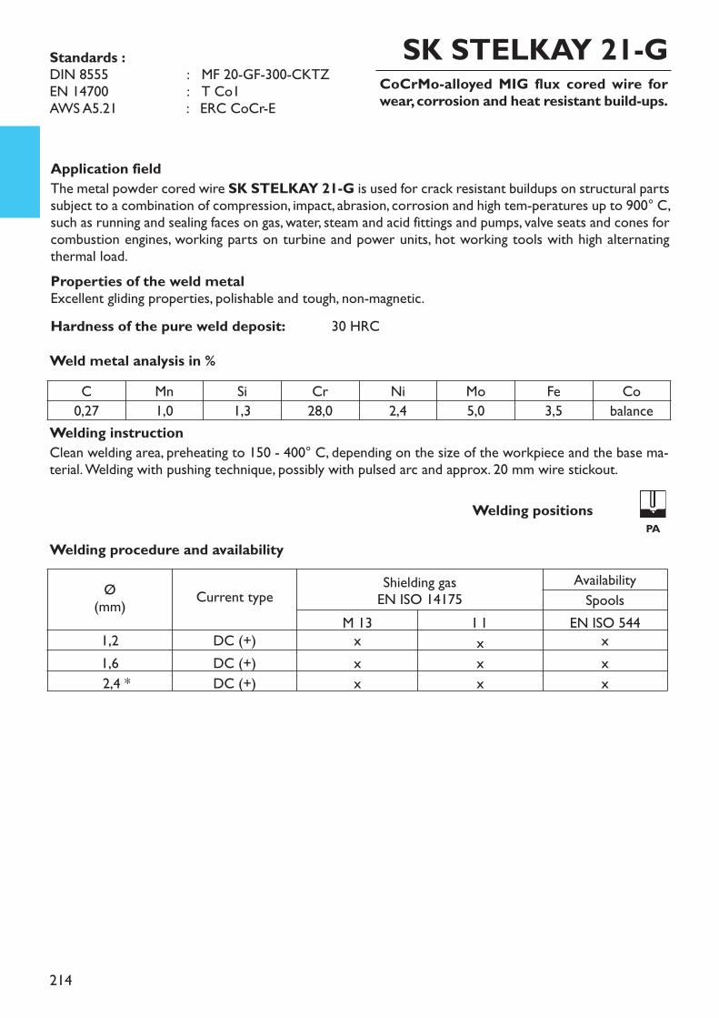
214
Application fieldThe metal powder cored wire SK STELKAY 21-G is used for crack resistant buildups on structural partssubject to a combination of compression, impact, abrasion, corrosion and high tem-peratures up to 900° C,such as running and sealing faces on gas, water, steam and acid fittings and pumps, valve seats and cones forcombustion engines, working parts on turbine and power units, hot working tools with high alternatingthermal load.Properties of the weld metalExcellent gliding properties, polishable and tough, non-magnetic.Hardness of the pure weld deposit: 30 HRC
Welding instructionClean welding area, preheating to 150 - 400° C, depending on the size of the workpiece and the base ma-terial. Welding with pushing technique, possibly with pulsed arc and approx. 20 mm wire stickout.
Weld metal analysis in %
CoCrMo-alloyed MIG flux cored wire forwear, corrosion and heat resistant build-ups.
SK STELKAY 21-GStandards :DIN 8555 : MF 20-GF-300-CKTZEN 14700 : T Co1AWS A5.21 : ERC CoCr-E
Welding procedure and availability
Welding positionsPA
C Mn Si Cr Ni Mo Fe Co0,27 1,0 1,3 28,0 2,4 5,0 3,5 balance
Ø(mm) Current type Shielding gas
EN ISO 14175AvailabilitySpools
M 13 I 1 EN ISO 5441,2 DC (+) x x x1,6 DC (+) x x x2,4 * DC (+) x x x
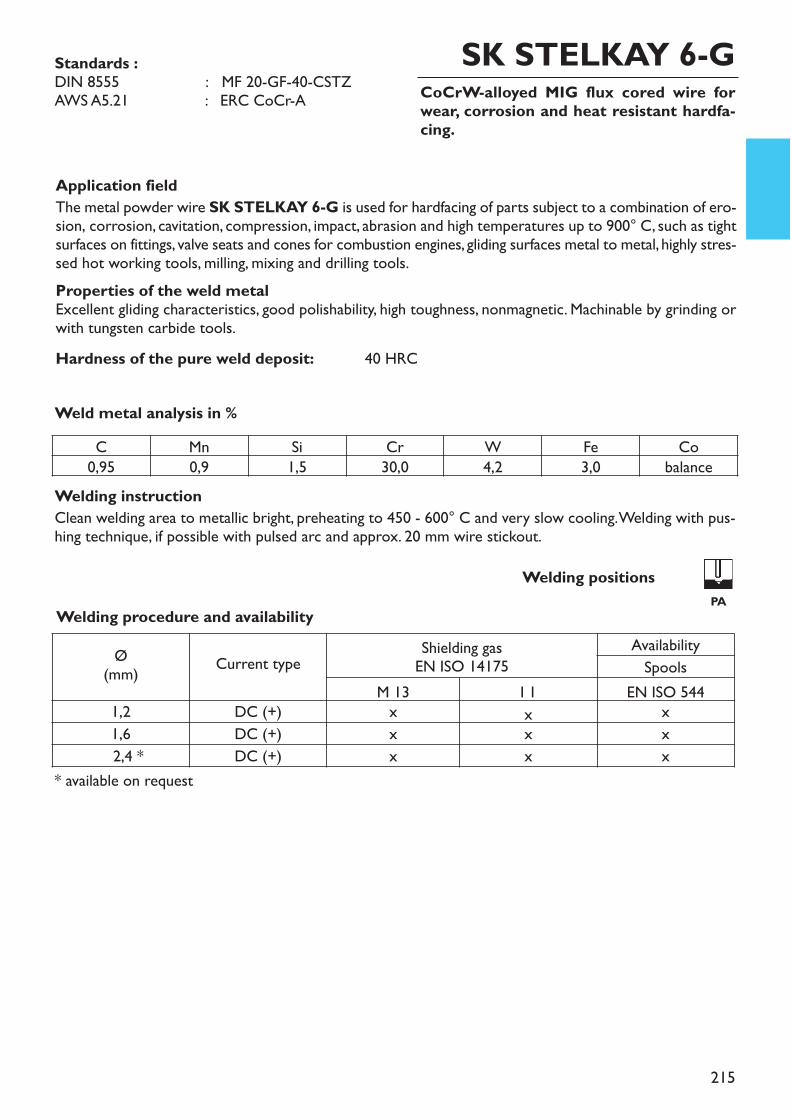
215
Application fieldThe metal powder wire SK STELKAY 6-G is used for hardfacing of parts subject to a combination of ero-sion, corrosion, cavitation, compression, impact, abrasion and high temperatures up to 900° C, such as tightsurfaces on fittings, valve seats and cones for combustion engines, gliding surfaces metal to metal, highly stres-sed hot working tools, milling, mixing and drilling tools. Properties of the weld metalExcellent gliding characteristics, good polishability, high toughness, nonmagnetic. Machinable by grinding orwith tungsten carbide tools.Hardness of the pure weld deposit: 40 HRC
Welding instructionClean welding area to metallic bright, preheating to 450 - 600° C and very slow cooling. Welding with pus-hing technique, if possible with pulsed arc and approx. 20 mm wire stickout.
Weld metal analysis in %
CoCrW-alloyed MIG flux cored wire forwear, corrosion and heat resistant hardfa-cing.
* available on request
SK STELKAY 6-GStandards :DIN 8555 : MF 20-GF-40-CSTZAWS A5.21 : ERC CoCr-A
Welding procedure and availabilityWelding positions
PA
C Mn Si Cr W Fe Co0,95 0,9 1,5 30,0 4,2 3,0 balance
Ø(mm) Current type Shielding gas
EN ISO 14175AvailabilitySpools
M 13 I 1 EN ISO 5441,2 DC (+) x x x1,6 DC (+) x x x2,4 * DC (+) x x x
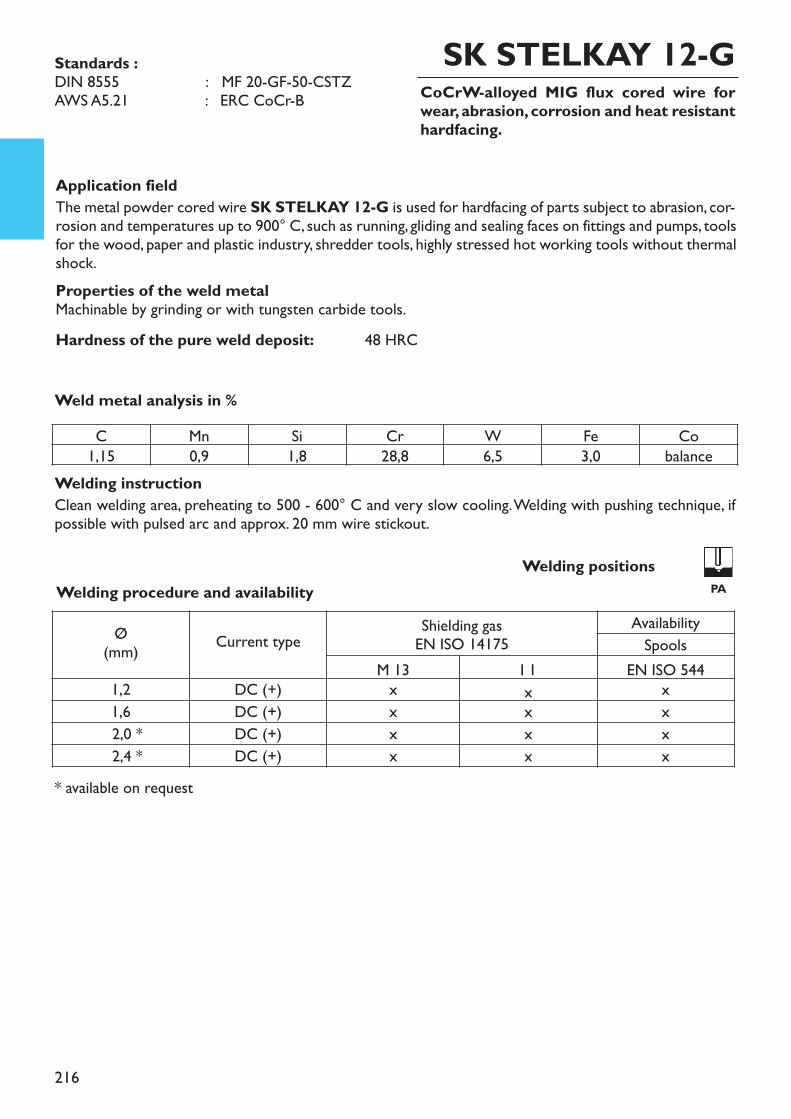
216
Application fieldThe metal powder cored wire SK STELKAY 12-G is used for hardfacing of parts subject to abrasion, cor-rosion and temperatures up to 900° C, such as running, gliding and sealing faces on fittings and pumps, toolsfor the wood, paper and plastic industry, shredder tools, highly stressed hot working tools without thermalshock.Properties of the weld metalMachinable by grinding or with tungsten carbide tools.Hardness of the pure weld deposit: 48 HRC
Welding instructionClean welding area, preheating to 500 - 600° C and very slow cooling. Welding with pushing technique, ifpossible with pulsed arc and approx. 20 mm wire stickout.
Weld metal analysis in %
CoCrW-alloyed MIG flux cored wire forwear, abrasion, corrosion and heat resistanthardfacing.
* available on request
SK STELKAY 12-GStandards :DIN 8555 : MF 20-GF-50-CSTZAWS A5.21 : ERC CoCr-B
Welding procedure and availabilityWelding positions
PA
C Mn Si Cr W Fe Co1,15 0,9 1,8 28,8 6,5 3,0 balance
Ø(mm) Current type Shielding gas
EN ISO 14175AvailabilitySpools
M 13 I 1 EN ISO 5441,2 DC (+) x x x1,6 DC (+) x x x2,0 * DC (+) x x x2,4 * DC (+) x x x
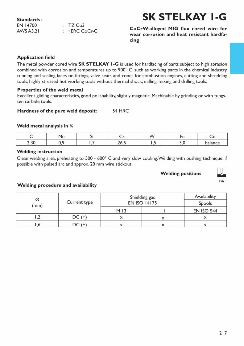
217
Application fieldThe metal powder cored wire SK STELKAY 1-G is used for hardfacing of parts subject to high abrasioncombined with corrosion and temperatures up to 900° C, such as working parts in the chemical industry,running and sealing faces on fittings, valve seats and cones for combustion engines, cutting and shreddingtools, highly stressed hot working tools without thermal shock, milling, mixing and drilling tools. Properties of the weld metalExcellent gliding characteristics, good polishability, slightly magnetic. Machinable by grinding or with tungs-ten carbide tools.Hardness of the pure weld deposit: 54 HRC
Welding instructionClean welding area, preheating to 500 - 600° C and very slow cooling. Welding with pushing technique, ifpossible with pulsed arc and approx. 20 mm wire stickout.
Weld metal analysis in %
CoCrW-alloyed MIG flux cored wire forwear corrosion and heat resistant hardfa-cing
Standards :EN 14700 : TZ Co3AWS A5.21 : ~ERC CoCr-C
SK STELKAY 1-G
Welding procedure and availabilityWelding positions
PA
C Mn Si Cr W Fe Co2,30 0,9 1,7 26,5 11,5 3,0 balance
Ø(mm) Current type Shielding gas
EN ISO 14175AvailabilitySpools
M 13 I 1 EN ISO 5441,2 DC (+) x x x1,6 DC (+) x x x
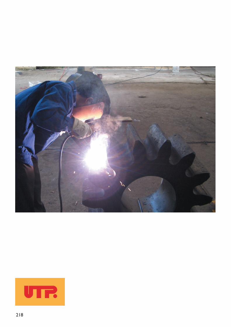
218
219
Index
Special alloys
stick electrodessolid rods and wires
Group 3Special alloys
220
Special alloys
stick electrodessolid rods and wires
223 – 234235 – 236
page
Group 3Special alloys
221
Stick electrodes
UTP 63
UTP 65
Rutile coated, fully austeniticCrNiMn-stick stick electrode. Uni-versally applicable.
Rutile coated austenitic-ferritic-special stick electrode with optimalwelding and mechanical properties.
UTP 65 D Rutile coated austenitic-ferritic-special stick electrode with high me-chanical properties for joinings andsurfacings.
page
223
226
227
UTP 630 Synthetic, rutile coated CrNiMn-stick electrode with 160 % recovery
224
UTP 6302 Rutile coated CrNiMn-stick stickelectrode. Universally applicable.
225
UTP 651 Synthetic austenitic-ferritic stickelectrode for joining and surfacingon hard to weld steels
228
UTP 653 Rutile coated austenitic special stickelectrode with high mechanical va-lues and excellent welding proper-ties.
229
Group 3Special alloys
E 8-UM-200-KRZE 18 8 Mn R 3 2E Fe10
~E 9-UM-250-KR~E 29 9 R 3 2EZ Fe11
StandardsDIN 8555EN 1600EN 14700
E 9-UM-250-KR~E 29 9 R 1 2EZ Fe11
E 8-UM-200-KRZE 18 8 Mn R 5 3E Fe10E 8-UM-200-KRZE 18 8 Mn R 3 2EZ Fe10
E 9-UM-250-KRE 29 9 R 7 3EZ Fe11E 8-UM-200-KRZ~E 23 12 2 L R 3 2EZ Fe11

222
UTP 7015 NK Basic-coated NiCrFe- high perfor-mance stick electrode with 150 % re-covery
page
UTP 6218 Mo Rutile-basic coated NiCrMo-high performance stick electrode.
231
232
UTP 82 AS Chamfering stick electrode for me-tallic materials
233
UTP 82 Ko Carbon stick electrode for arc-airgouging of all industrial metals
234
UTP 68 HH Basic coated, fully austenitic NiCr-stick electrode, universally applica-ble.
230
Solid rods and wires (TIG, MIG / MAG)
UTP A 63 Rods and wires for high-tensilejoints
page
235
UTP A 651 CrNi-rods and wires, austenitic-ferritic
236
StandardsEN 14172AWS A5.11
E Ni 6094E NiCrFe-3 (mod.)
E Ni 6620-
E Ni 6082-
--
--
W/G 18 8 MnER 307 (mod.)1.4370
StandardsEN ISO 14343-AAWS A5.9Material-No.
W/G 29 9-1.4337
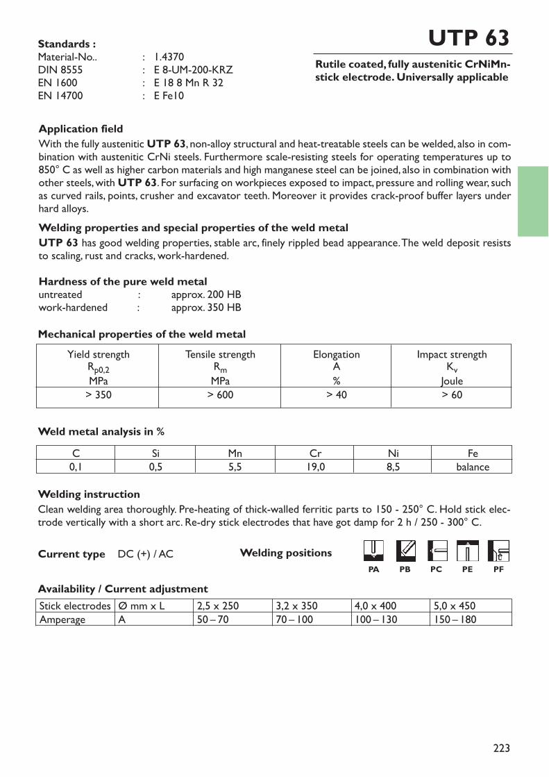
223
Yield strengthRp0,2MPa> 350
Tensile strengthRmMPa> 600
ElongationA%
> 40
Impact strengthKvJoule> 60
Mechanical properties of the weld metal
Rutile coated, fully austenitic CrNiMn-stick electrode. Universally applicable
UTP 63
Welding instructionClean welding area thoroughly. Pre-heating of thick-walled ferritic parts to 150 - 250° C. Hold stick elec-trode vertically with a short arc. Re-dry stick electrodes that have got damp for 2 h / 250 - 300° C.
Availability / Current adjustment
Current type DC (+) / AC
Application fieldWith the fully austenitic UTP 63, non-alloy structural and heat-treatable steels can be welded, also in com-bination with austenitic CrNi steels. Furthermore scale-resisting steels for operating temperatures up to850° C as well as higher carbon materials and high manganese steel can be joined, also in combination withother steels, with UTP 63. For surfacing on workpieces exposed to impact, pressure and rolling wear, suchas curved rails, points, crusher and excavator teeth. Moreover it provides crack-proof buffer layers underhard alloys.Welding properties and special properties of the weld metalUTP 63 has good welding properties, stable arc, finely rippled bead appearance. The weld deposit resiststo scaling, rust and cracks, work-hardened.Hardness of the pure weld metaluntreated : approx. 200 HBwork-hardened : approx. 350 HB
Weld metal analysis in %
Standards :Material-No.. : 1.4370DIN 8555 : E 8-UM-200-KRZEN 1600 : E 18 8 Mn R 32EN 14700 : E Fe10
C0,1
Si0,5
Mn5,5
Cr19,0
Ni8,5
Febalance
Stick electrodesAmperage
Ø mm x LA
2,5 x 25050 – 70
3,2 x 35070 – 100
4,0 x 400100 – 130
5,0 x 450150 – 180
Welding positionsPA PB PC PE PF
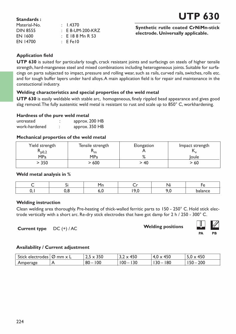
224
Synthetic rutile coated CrNiMn-stickelectrode. Universally applicable.
UTP 630
Welding instructionClean welding area thoroughly. Pre-heating of thick-walled ferritic parts to 150 - 250° C. Hold stick elec-trode vertically with a short arc. Re-dry stick electrodes that have got damp for 2 h / 250 - 300° C.
Availability / Current adjustment
Current type DC (+) / AC
Application fieldUTP 630 is suited for particularly tough, crack resistant joints and surfacings on steels of higher tensilestrength, hard-manganese steel and mixed combinations including heterogeneous joints. Suitable for surfa-cings on parts subjected to impact, pressure and rolling wear, such as rails, curved rails, switches, rolls etc.and for tough buffer layers under hard alloys. A main application field is for repair and maintenance in theconstuctional industry.Welding characteristics and special properties of the weld metalUTP 630 is easily weldable with stable arc, homogeneous, finely rippled bead appearance and gives goodslag removal. The fully austenitic weld metal is resistant to rust and scale up to 850° C, workhardening.Hardness of the pure weld metaluntreated : approx. 200 HBwork-hardened : approx. 350 HB
Weld metal analysis in %
Yield strengthRp0,2MPa> 350
Tensile strengthRmMPa> 600
ElongationA%
> 40
Impact strengthKvJoule> 60
Mechanical properties of the weld metal
Standards :Material-No. : 1.4370DIN 8555 : E 8-UM-200-KRZEN 1600 : E 18 8 Mn R 53EN 14700 : E Fe10
C0,1
Si0,8
Mn6,0
Cr19,0
Ni9,0
Febalance
Stick electrodesAmperage
Ø mm x LA
2,5 x 35080 – 100
3,2 x 450100 – 130
4,0 x 450130 – 180
5,0 x 450150 – 200
Welding positionsPA PB
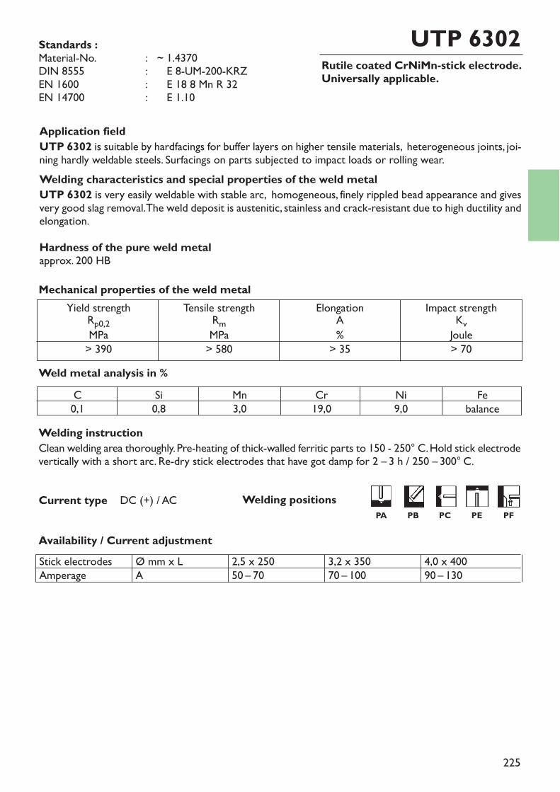
225
Rutile coated CrNiMn-stick electrode.Universally applicable.
UTP 6302
Welding instructionClean welding area thoroughly. Pre-heating of thick-walled ferritic parts to 150 - 250° C. Hold stick electrodevertically with a short arc. Re-dry stick electrodes that have got damp for 2 – 3 h / 250 – 300° C.
Availability / Current adjustment
Current type DC (+) / AC
Application fieldUTP 6302 is suitable by hardfacings for buffer layers on higher tensile materials, heterogeneous joints, joi-ning hardly weldable steels. Surfacings on parts subjected to impact loads or rolling wear.Welding characteristics and special properties of the weld metalUTP 6302 is very easily weldable with stable arc, homogeneous, finely rippled bead appearance and givesvery good slag removal. The weld deposit is austenitic, stainless and crack-resistant due to high ductility andelongation.Hardness of the pure weld metalapprox. 200 HB
Weld metal analysis in %
Yield strengthRp0,2MPa> 390
Tensile strengthRmMPa> 580
ElongationA%
> 35
Impact strengthKvJoule> 70
Mechanical properties of the weld metal
Standards :Material-No. : ~ 1.4370DIN 8555 : ~ E 8-UM-200-KRZEN 1600 : ~ E 18 8 Mn R 32EN 14700 : ~ E 1.10
C0,1
Si0,8
Mn3,0
Cr19,0
Ni9,0
Febalance
Stick electrodesAmperage
Ø mm x LA
2,5 x 25050 – 70
3,2 x 35070 – 100
4,0 x 40090 – 130
Welding positions PA PB PC PE PF
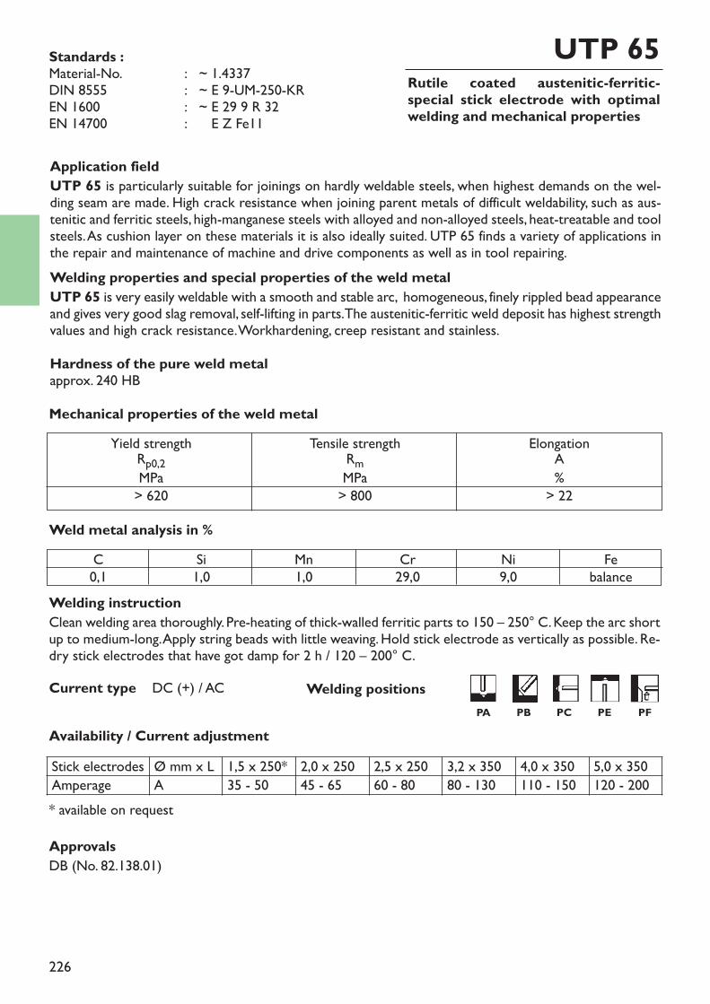
226
Rutile coated austenitic-ferritic-special stick electrode with optimalwelding and mechanical properties
UTP 65
Welding instructionClean welding area thoroughly. Pre-heating of thick-walled ferritic parts to 150 – 250° C. Keep the arc shortup to medium-long. Apply string beads with little weaving. Hold stick electrode as vertically as possible. Re-dry stick electrodes that have got damp for 2 h / 120 – 200° C.
Availability / Current adjustment
Current type DC (+) / AC
Application fieldUTP 65 is particularly suitable for joinings on hardly weldable steels, when highest demands on the wel-ding seam are made. High crack resistance when joining parent metals of difficult weldability, such as aus-tenitic and ferritic steels, high-manganese steels with alloyed and non-alloyed steels, heat-treatable and toolsteels. As cushion layer on these materials it is also ideally suited. UTP 65 finds a variety of applications inthe repair and maintenance of machine and drive components as well as in tool repairing.Welding properties and special properties of the weld metalUTP 65 is very easily weldable with a smooth and stable arc, homogeneous, finely rippled bead appearanceand gives very good slag removal, self-lifting in parts. The austenitic-ferritic weld deposit has highest strengthvalues and high crack resistance. Workhardening, creep resistant and stainless.Hardness of the pure weld metalapprox. 240 HB
Weld metal analysis in %
* available on request
Yield strengthRp0,2MPa> 620
Tensile strengthRmMPa> 800
ElongationA%
> 22
Mechanical properties of the weld metal
Standards :Material-No. : ~ 1.4337DIN 8555 : ~ E 9-UM-250-KREN 1600 : ~ E 29 9 R 32EN 14700 : ~ E Z Fe11
C0,1
Si1,0
Mn1,0
Cr29,0
Ni9,0
Febalance
Stick electrodes Ø mm x L 1,5 x 250* 2,0 x 250 2,5 x 250 3,2 x 350 4,0 x 350 5,0 x 350Amperage A 35 - 50 45 - 65 60 - 80 80 - 130 110 - 150 120 - 200
ApprovalsDB (No. 82.138.01)
Welding positionsPA PB PC PE PF
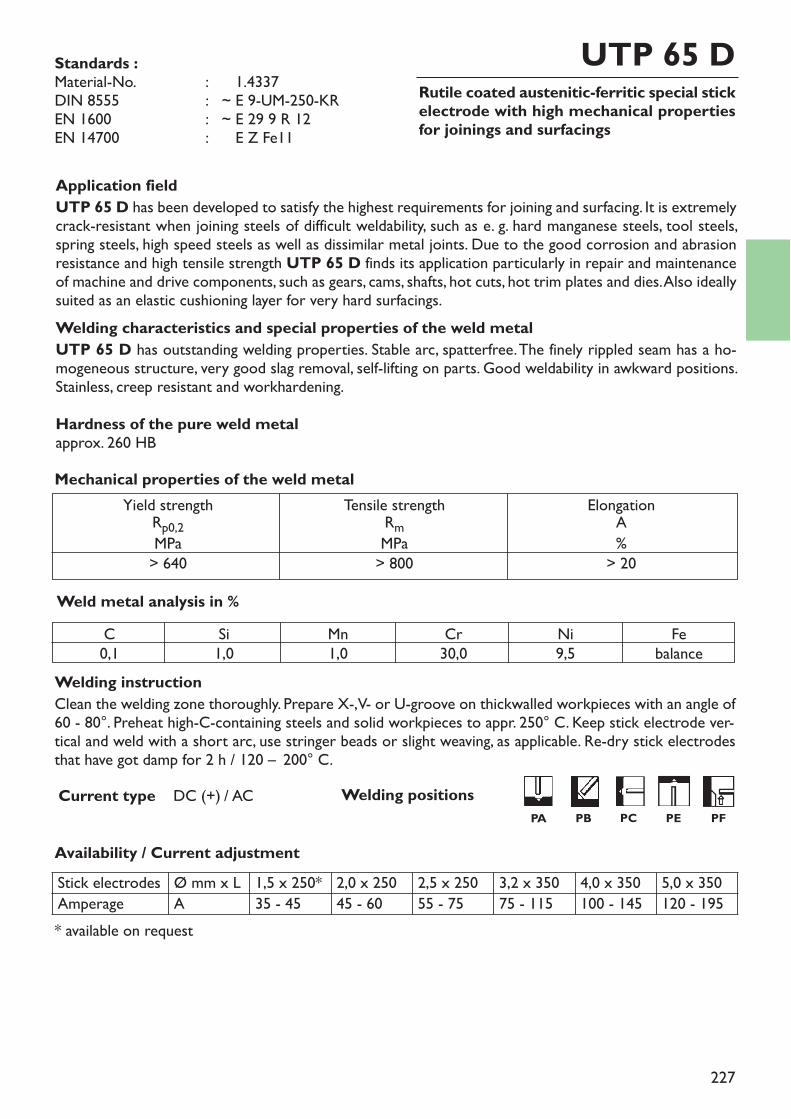
Stick electrodes Ø mm x L 1,5 x 250* 2,0 x 250 2,5 x 250 3,2 x 350 4,0 x 350 5,0 x 350Amperage A 35 - 45 45 - 60 55 - 75 75 - 115 100 - 145 120 - 195
227
Rutile coated austenitic-ferritic special stickelectrode with high mechanical propertiesfor joinings and surfacings
UTP 65 D
Welding instructionClean the welding zone thoroughly. Prepare X-, V- or U-groove on thickwalled workpieces with an angle of60 - 80°. Preheat high-C-containing steels and solid workpieces to appr. 250° C. Keep stick electrode ver-tical and weld with a short arc, use stringer beads or slight weaving, as applicable. Re-dry stick electrodesthat have got damp for 2 h / 120 – 200° C.
Availability / Current adjustment
Current type DC (+) / AC
Application fieldUTP 65 D has been developed to satisfy the highest requirements for joining and surfacing. It is extremelycrack-resistant when joining steels of difficult weldability, such as e. g. hard manganese steels, tool steels,spring steels, high speed steels as well as dissimilar metal joints. Due to the good corrosion and abrasionresistance and high tensile strength UTP 65 D finds its application particularly in repair and maintenanceof machine and drive components, such as gears, cams, shafts, hot cuts, hot trim plates and dies. Also ideallysuited as an elastic cushioning layer for very hard surfacings.Welding characteristics and special properties of the weld metalUTP 65 D has outstanding welding properties. Stable arc, spatterfree. The finely rippled seam has a ho-mogeneous structure, very good slag removal, self-lifting on parts. Good weldability in awkward positions.Stainless, creep resistant and workhardening.Hardness of the pure weld metalapprox. 260 HB
Weld metal analysis in %
* available on request
Yield strengthRp0,2MPa> 640
Tensile strengthRmMPa> 800
ElongationA%
> 20
Mechanical properties of the weld metal
Standards :Material-No. : ~ 1.4337DIN 8555 : ~ E 9-UM-250-KREN 1600 : ~ E 29 9 R 12EN 14700 : ~ E Z Fe11
C0,1
Si1,0
Mn1,0
Cr30,0
Ni9,5
Febalance
Welding positionsPA PB PC PE PF
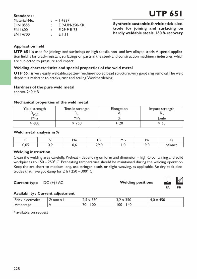
228
Synthetic austenitic-ferritic stick elec-trode for joining and surfacing onhardly weldable steels. 160 % recovery.
UTP 651
Welding instructionClean the welding area carefully. Preheat - depending on form and dimension - high C-containing and solidworkpieces to 150 – 250° C. Preheating temperature should be maintained during the welding operation.Keep the arc short to medium-long, use stringer beads or slight weaving, as applicable. Re-dry stick elec-trodes that have got damp for 2 h / 250 – 300° C.
Availability / Current adjustment
Current type DC (+) / AC
Application fieldUTP 651 is used for joinings and surfacings on high-tensile non- and low-alloyed steels. A special applica-tion field is for crack-resistant surfacings on parts in the steel- and construction machinery industries, whichare subjected to pressure and impact.Welding characteristics and special properties of the weld metalUTP 651 is very easily weldable, spatter-free, fine-rippled bead structure, very good slag removal. The welddeposit is resistant to cracks, rust and scaling. Workhardening.Hardness of the pure weld metalapprox. 240 HB
Weld metal analysis in %
* available on request
Yield strengthRp0,2MPa> 600
Tensile strengthRmMPa> 750
ElongationA%
> 20
Impact strengthKvJoule> 60
Mechanical properties of the weld metal
Standards :Material-No. : ~ 1.4337DIN 8555 : ~ E 9-UM-250-KREN 1600 : ~ E 29 9 R 73EN 14700 : ~ E 1.11
C0,05
Si0,9
Mn0,6
Cr29,0
Mo1,0
Ni9,0
Febalance
Stick electrodesAmperage
Ø mm x LA
2,5 x 35070 – 100
3,2 x 350100 – 140
4,0 x 450
Welding positionsPA PB
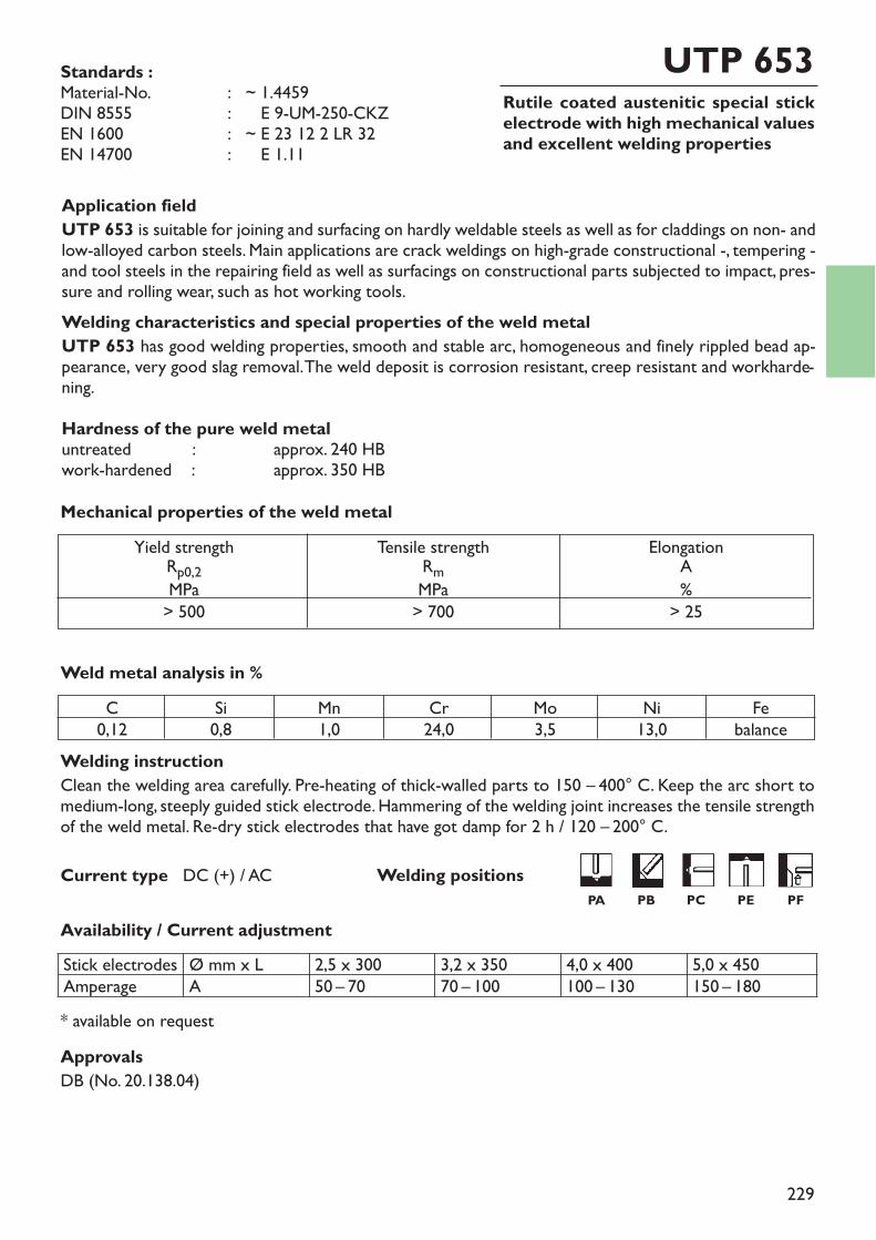
229
Rutile coated austenitic special stickelectrode with high mechanical valuesand excellent welding properties
UTP 653
Welding instructionClean the welding area carefully. Pre-heating of thick-walled parts to 150 – 400° C. Keep the arc short tomedium-long, steeply guided stick electrode. Hammering of the welding joint increases the tensile strengthof the weld metal. Re-dry stick electrodes that have got damp for 2 h / 120 – 200° C.
Availability / Current adjustment
Current type DC (+) / AC
Application fieldUTP 653 is suitable for joining and surfacing on hardly weldable steels as well as for claddings on non- andlow-alloyed carbon steels. Main applications are crack weldings on high-grade constructional -, tempering -and tool steels in the repairing field as well as surfacings on constructional parts subjected to impact, pres-sure and rolling wear, such as hot working tools.Welding characteristics and special properties of the weld metalUTP 653 has good welding properties, smooth and stable arc, homogeneous and finely rippled bead ap-pearance, very good slag removal. The weld deposit is corrosion resistant, creep resistant and workharde-ning.Hardness of the pure weld metaluntreated : approx. 240 HBwork-hardened : approx. 350 HB
Weld metal analysis in %
* available on request
Yield strengthRp0,2MPa> 500
Tensile strengthRmMPa> 700
ElongationA%
> 25
Mechanical properties of the weld metal
Standards :Material-No. : ~ 1.4459DIN 8555 : ~ E 9-UM-250-CKZEN 1600 : ~ E 23 12 2 LR 32EN 14700 : ~ E 1.11
C0,12
Si0,8
Mn1,0
Cr24,0
Mo3,5
Ni13,0
Febalance
Stick electrodesAmperage
Ø mm x LA
2,5 x 30050 – 70
3,2 x 35070 – 100
4,0 x 400100 – 130
5,0 x 450150 – 180
ApprovalsDB (No. 20.138.04)
Welding positionsPA PB PC PE PF

230
Basic coated, fully austenitic NiCr-stickelectrode, universally applicable.
UTP 68 HH
Welding instructionClean welding area to metallic bright. Pre-heating of thick-walled ferritic parts to 150 – 350° C, dependingon C-content. Apply string beads - if necessary, with little weaving. Keep a short arc and low amperage set-ting. Use only dry stick electrodes. Re-drying for 2 – 3 h / 250 – 300° C.
Current type DC (+)
Application fieldUTP 68 HH is suited for joining ferrous alloys, nickel and nickel alloys, copper and copper alloys, also thevarious groups with each other. The main applications are constructional and repair welds on heat resistantmaterials, high-strength constructional and tempering steels, tool steels and corrosion resistant steels andnickel alloys.Welding properties and special characteristics of the weld metalUTP 68 HH has a good weldability by a steep guidance and a short arc. The weld deposit is resistant tocorrosion, scale, creep, cracks and it is very tough. Unsusceptible to embrittlement. No carbon diffusion intothe weld metal even at high temperatures, cold-tough. Not to be used in sulphureous medias!Hardness of the pure weld metalapprox. 180 HB
Weld metal analysis in %
Availability / Current adjustment
* available on request
Yield strengthRp0,2MPa> 390
Tensile strengthRmMPa> 620
ElongationA%
> 35
Impact strengthKvJoule> 80
Mechanical properties of the weld metal
Standards :Material-No. : 2.4648EN ISO 14172 : E Ni 6082
(NiCr20Mn3Nb)AWS A5.11 : E NiCrFe-3 (mod.)
C0,03
Si0,4
Mn5,0
Cr19,0
Nibalance
Nb2,0
Fe3,0
Stick electrodesAmperage
Ø mm x LA
2,5 x 30040 – 65
3,2 x 30070 – 100
4,0 x 350100 – 120
5,0 x 400130 – 150
ApprovalsTÜV (No. 00230)
Welding positionsPA PB PC PE PF
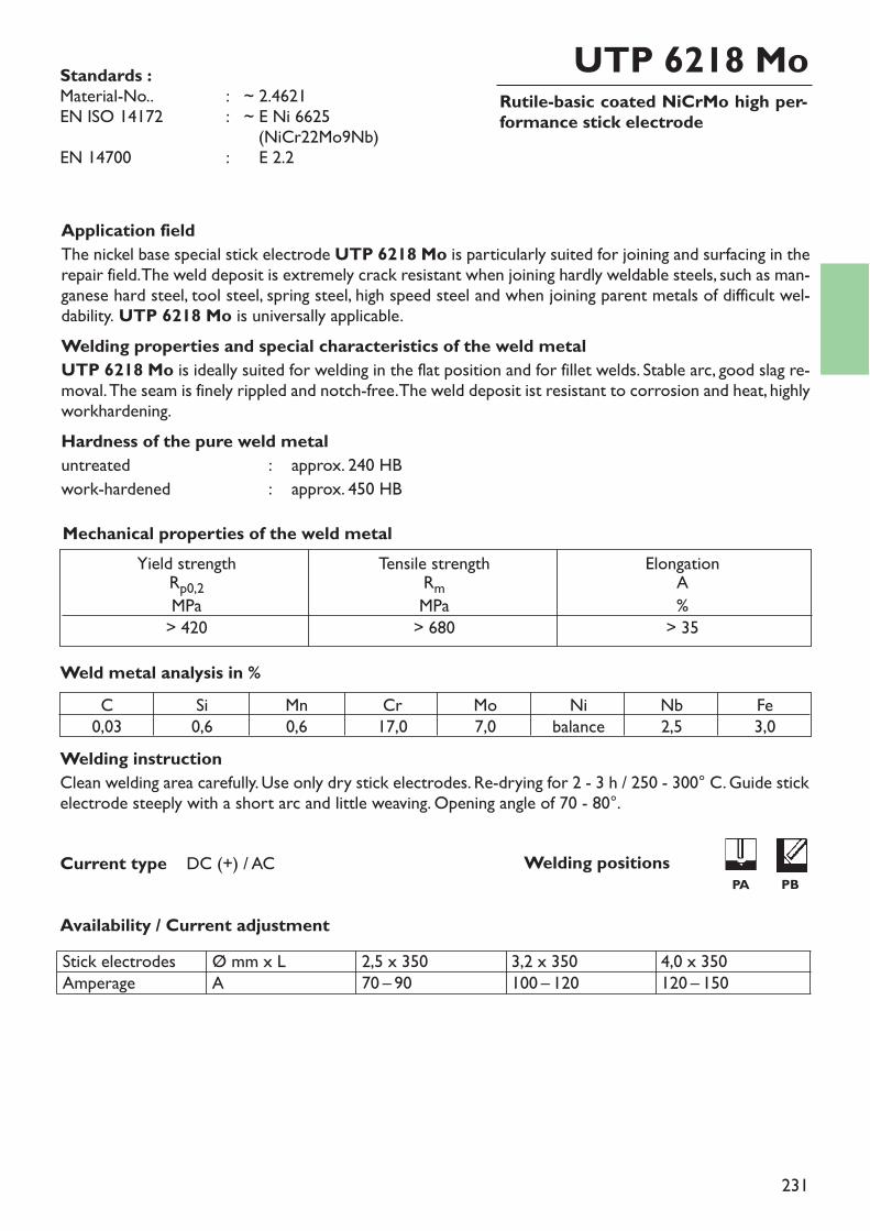
231
Rutile-basic coated NiCrMo high per-formance stick electrode
UTP 6218 Mo
Welding instructionClean welding area carefully. Use only dry stick electrodes. Re-drying for 2 - 3 h / 250 - 300° C. Guide stickelectrode steeply with a short arc and little weaving. Opening angle of 70 - 80°.
Availability / Current adjustment
Current type DC (+) / AC
Application fieldThe nickel base special stick electrode UTP 6218 Mo is particularly suited for joining and surfacing in therepair field. The weld deposit is extremely crack resistant when joining hardly weldable steels, such as man-ganese hard steel, tool steel, spring steel, high speed steel and when joining parent metals of difficult wel-dability. UTP 6218 Mo is universally applicable.Welding properties and special characteristics of the weld metalUTP 6218 Mo is ideally suited for welding in the flat position and for fillet welds. Stable arc, good slag re-moval. The seam is finely rippled and notch-free. The weld deposit ist resistant to corrosion and heat, highlyworkhardening.Hardness of the pure weld metaluntreated : approx. 240 HBwork-hardened : approx. 450 HB
Weld metal analysis in %
Yield strengthRp0,2MPa> 420
Tensile strengthRmMPa> 680
ElongationA%
> 35
Mechanical properties of the weld metal
Standards :Material-No.. : ~ 2.4621EN ISO 14172 : ~ E Ni 6625
(NiCr22Mo9Nb)EN 14700 : ~ E 2.2
C0,03
Si0,6
Mn0,6
Cr17,0
Mo7,0
Nibalance
Nb2,5
Fe3,0
Stick electrodesAmperage
Ø mm x LA
2,5 x 35070 – 90
3,2 x 350100 – 120
4,0 x 350120 – 150
Welding positionsPA PB
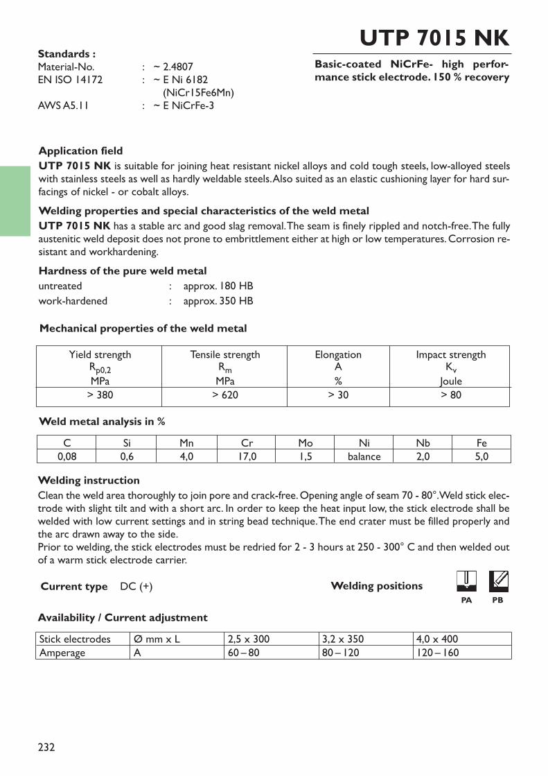
232
Basic-coated NiCrFe- high perfor-mance stick electrode. 150 % recovery
UTP 7015 NK
Welding instructionClean the weld area thoroughly to join pore and crack-free. Opening angle of seam 70 - 80°. Weld stick elec-trode with slight tilt and with a short arc. In order to keep the heat input low, the stick electrode shall bewelded with low current settings and in string bead technique. The end crater must be filled properly andthe arc drawn away to the side.Prior to welding, the stick electrodes must be redried for 2 - 3 hours at 250 - 300° C and then welded outof a warm stick electrode carrier.
Availability / Current adjustment
Current type DC (+)
Application fieldUTP 7015 NK is suitable for joining heat resistant nickel alloys and cold tough steels, low-alloyed steelswith stainless steels as well as hardly weldable steels. Also suited as an elastic cushioning layer for hard sur-facings of nickel - or cobalt alloys.Welding properties and special characteristics of the weld metalUTP 7015 NK has a stable arc and good slag removal. The seam is finely rippled and notch-free. The fullyaustenitic weld deposit does not prone to embrittlement either at high or low temperatures. Corrosion re-sistant and workhardening.Hardness of the pure weld metaluntreated : approx. 180 HBwork-hardened : approx. 350 HB
Weld metal analysis in %
Yield strengthRp0,2MPa> 380
Tensile strengthRmMPa> 620
ElongationA%
> 30
Impact strengthKvJoule> 80
Mechanical properties of the weld metal
Standards :Material-No. : ~ 2.4807EN ISO 14172 : ~ E Ni 6182
(NiCr15Fe6Mn)AWS A5.11 : ~ E NiCrFe-3
C0,08
Si0,6
Mn4,0
Cr17,0
Mo1,5
Nibalance
Nb2,0
Fe5,0
Stick electrodesAmperage
Ø mm x LA
2,5 x 30060 – 80
3,2 x 35080 – 120
4,0 x 400120 – 160
Welding positionsPA PB
233
Chamfering stick electrode for metal-lic materials
UTP 82 AS
Availability / Current adjustment
Application fieldThe strongly coated chamfering stick electrode UTP 82 AS can be used on all steel grades with ferriticand austenitic structure, as well as cast iron, cast steel and all non-ferrous metals. It enables workpieces tobe grooved out in a very simple way. UTP 82 AS is also suitable for removing corroded metal layers andfor fusion-cutting metallic materials.Welding propertiesUTP 82 AS strikes easily and generates a high gas pressure, enabling a clean and smooth cut to be achie-ved.Welding instructionWhen grooving it is advisable to tilt the plate in the direction of working, so that the molten parent metalcan run off better. The stick electrode should be inclined to the parent metal as horizontally as possible (ap-prox. 15°) and kept constantly in contact with it. The working speed is increased by slight pushing move-ments in the direction of working. Parent metal left on the edge of the groove is easily removed with theslag hammer. Machining the groove down to the bare metal may be advisable, depending on the circum-stances.
* available on request
Current type = – ~
Stick electrodesAmperage
Ø mm x LA
2,5 x 250150 – 250
3,2 x 350200 – 300
4,0 x 350250 – 400
5,0 x 350
234
Carbon stick electrode for arc-air gou-ging of all industrial metals
UTP 82 Ko
Availability / Current adjustment
Current type : DC (+)
Application fieldUTP 82 Ko is suited for pointing and cutting of all metals melting in the arc, such as all steels and cast steels,cast iron materials, aluminium-, nickel- and copper alloys.Special propertiesHigh pointing rate, universally applicable, high economic efficiency.Welding instructionHigh tensile steels susceptible to a hardness increase should be preheated to 150 - 400° C, just as copper.Compressed air approx. 4,5 bar
Stick electrodesAmperage
Ø mm x LA
4,0 x 305180 - 220
8,0 x 305*350 – 500
9,5 x 305*500 – 650
* available on request
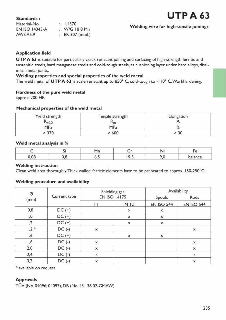
235
Welding wire for high-tensile joiningsUTP A 63
Application fieldUTP A 63 is suitable for particularly crack resistant joining and surfacing of high-strength ferritic andaustenitic steels, hard manganese steels and cold-tough steels, as cushioning layer under hard alloys, dissi-milar metal joints.Welding properties and special properties of the weld metalThe weld metal of UTP A 63 is scale resistant up to 850° C, cold-tough to -110° C. Workhardening.Hardness of the pure weld metalapprox. 200 HB
Weld metal analysis in %
Standards :Material-No. : 1.4370EN ISO 14343-A : W/G 18 8 MnAWS A5.9 : ER 307 (mod.)
Mechanical properties of the weld metalYield strengthRp0,2MPa
> 370
Tensile strengthRmMPa> 600
ElongationA%
> 30
C Si Mn Cr Ni Fe0,08 0,8 6,5 19,5 9,0 balance
ApprovalsTÜV (No. 04096; 04097), DB (No. 43.138.02-GMAW)
Welding instructionClean weld area thoroughly. Thick walled, ferritic elements have to be preheated to approx. 150-250°C.Welding procedure and availability
Ø(mm) Current type Shielding gas
EN ISO 14175Availability
Spools RodsI 1 M 12 EN ISO 544 EN ISO 544
0,8 DC (+) x x1,0 DC (+) x x1,2 DC (+) x x1,2 * DC (-) x x1,6 DC (+) x x1,6 DC (-) x x2,0 DC (-) x x2,4 DC (-) x x3,2 DC (-) x x
* available on request
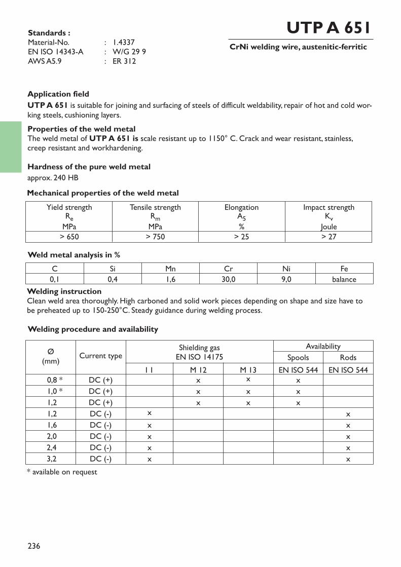
236
CrNi welding wire, austenitic-ferriticUTP A 651
Application fieldUTP A 651 is suitable for joining and surfacing of steels of difficult weldability, repair of hot and cold wor-king steels, cushioning layers.Properties of the weld metalThe weld metal of UTP A 651 is scale resistant up to 1150° C. Crack and wear resistant, stainless,creep resistant and workhardening.Hardness of the pure weld metalapprox. 240 HB
Weld metal analysis in %
Standards :Material-No. : 1.4337EN ISO 14343-A : W/G 29 9AWS A5.9 : ER 312
* available on request
Mechanical properties of the weld metalYield strengthReMPa
> 650
Tensile strengthRmMPa> 750
ElongationA5%> 25
Impact strengthKvJoule> 27
C Si Mn Cr Ni Fe0,1 0,4 1,6 30,0 9,0 balance
Welding instructionClean weld area thoroughly. High carboned and solid work pieces depending on shape and size have tobe preheated up to 150-250°C. Steady guidance during welding process.Welding procedure and availability
Ø(mm) Current type Shielding gas
EN ISO 14175Availability
Spools RodsI 1 M 12 M 13 EN ISO 544 EN ISO 544
0,8 * DC (+) x x x1,0 * DC (+) x x x1,2 DC (+) x x x1,2 DC (-) x x1,6 DC (-) x x2,0 DC (-) x x2,4 DC (-) x x3,2 DC (-) x x
237
238
Index
Welding consumables for cast iron materials
stick electrodessolid rods and wiresflux cored wires
Group 4Welding consumablesfor cast iron materials
239
Welding consumables for cast iron materials
stick electrodessolid rods and wiresflux cored wires
244 – 257258 – 260
261
page
Group 4Welding consumablesfor cast iron materials
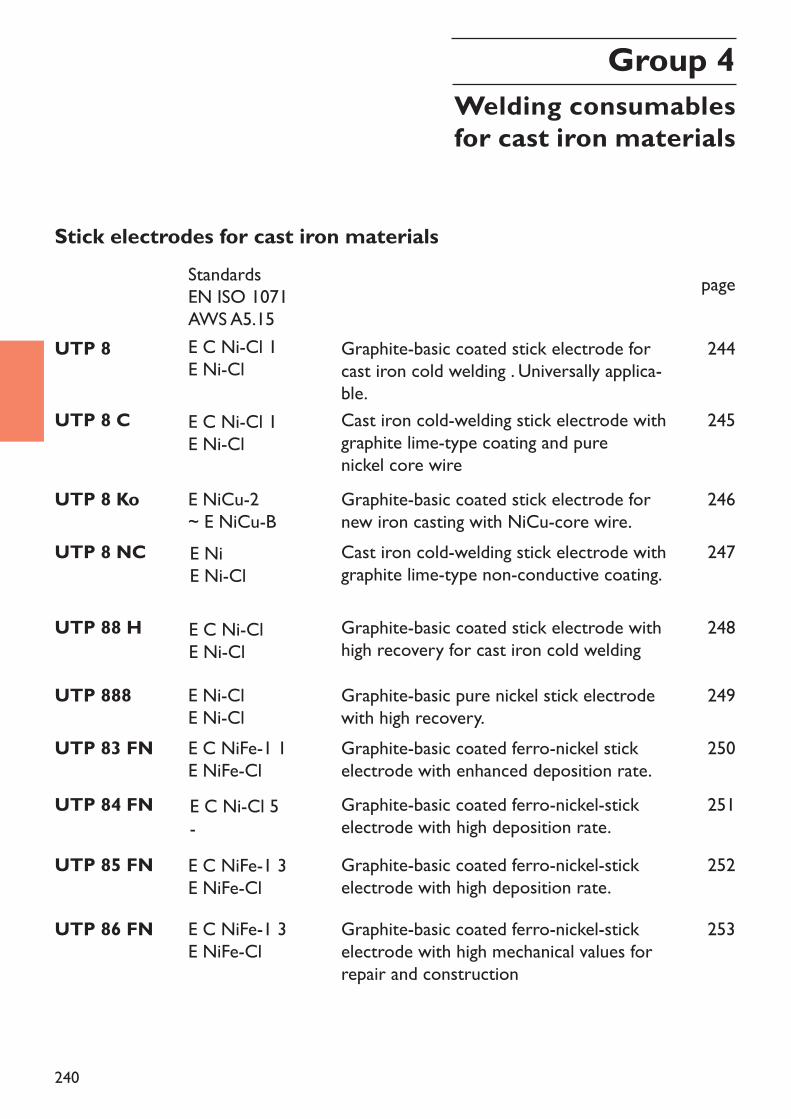
240
Stick electrodes for cast iron materials
UTP 8 Graphite-basic coated stick electrode forcast iron cold welding . Universally applica-ble.
UTP 8 C Cast iron cold-welding stick electrode withgraphite lime-type coating and pure nickel core wire
page
244
245
UTP 8 Ko Graphite-basic coated stick electrode fornew iron casting with NiCu-core wire.
246
UTP 8 NC Cast iron cold-welding stick electrode withgraphite lime-type non-conductive coating.
247
UTP 83 FN Graphite-basic coated ferro-nickel stickelectrode with enhanced deposition rate.
250
UTP 88 H Graphite-basic coated stick electrode withhigh recovery for cast iron cold welding
248
UTP 888 Graphite-basic pure nickel stick electrodewith high recovery.
249
UTP 84 FN Graphite-basic coated ferro-nickel-stickelectrode with high deposition rate.
251
252UTP 85 FN Graphite-basic coated ferro-nickel-stickelectrode with high deposition rate.
UTP 86 FN Graphite-basic coated ferro-nickel-stickelectrode with high mechanical values forrepair and construction
253
Group 4Welding consumablesfor cast iron materials
StandardsEN ISO 1071AWS A5.15E C Ni-Cl 1E Ni-Cl
E C Ni-Cl 1E Ni-Cl
E NiCu-2~ E NiCu-BE NiE Ni-Cl
E C NiFe-1 1E NiFe-Cl
E C Ni-ClE Ni-ClE Ni-ClE Ni-Cl
E C Ni-Cl 5-E C NiFe-1 3E NiFe-ClE C NiFe-1 3E NiFe-Cl
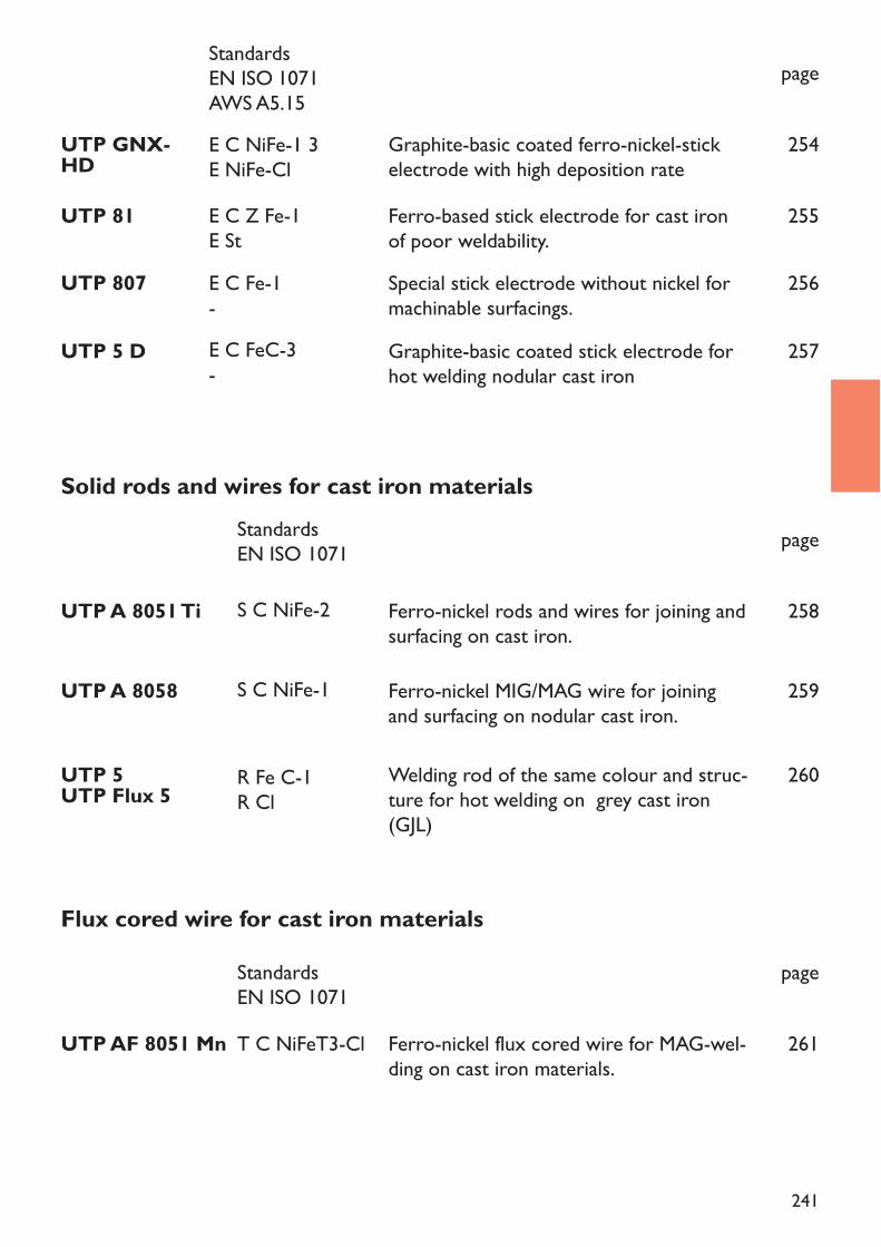
241
page
UTP 807 Special stick electrode without nickel formachinable surfacings.
256
UTP GNX-HD Graphite-basic coated ferro-nickel-stickelectrode with high deposition rate
254
UTP 5 D Graphite-basic coated stick electrode forhot welding nodular cast iron
257
UTP 81 Ferro-based stick electrode for cast ironof poor weldability.
255
Solid rods and wires for cast iron materials
UTP 5UTP Flux 5
UTP A 8051 Ti
Welding rod of the same colour and struc-ture for hot welding on grey cast iron(GJL)
Ferro-nickel rods and wires for joining andsurfacing on cast iron.
page
260
UTP A 8058 Ferro-nickel MIG/MAG wire for joiningand surfacing on nodular cast iron.
259
Flux cored wire for cast iron materials
UTP AF 8051 Mn T C NiFeT3-Cl
StandardsEN ISO 1071
Ferro-nickel flux cored wire for MAG-wel-ding on cast iron materials.
page
261
258
StandardsEN ISO 1071AWS A5.15
E C Fe-1-
E C NiFe-1 3E NiFe-Cl
E C FeC-3-
E C Z Fe-1E St
R Fe C-1R Cl
S C NiFe-2
StandardsEN ISO 1071
S C NiFe-1
242
Application fields for cast iron welding areRepair weldingProduction welding Construction welding
Repair welding is to recondition damaged (cracked, broken or worn out) cast iron parts bywelding to ensure further use.
Production welding means that a welding is needed within a production process of a cast ironpart to ensure particular properties. Such weldings may be repair of foundry defects, cor-rection of measurements or claddings.Construction welding is to join cast iron parts to components of other materials in a con-struction unit. Casting part used in this field are usually made of nodular- or malleable castiron. Typical weldings are
tubes and flanches made of ductile cast ironjoining of cast iron with un- or high alloyed steelwelding of wear resistant Mn-steel plates on to cast iron
In general 2 methods of cast iron welding are used:the cold welding with non matching consumablesthe hot welding with matching consumables
Hot weldingHot welding is being done with stick electrodes, gas welding rods or cored wires giving a co-lour and structure matching deposit.Hot welding of cast iron needs a high pre-heating temperature of 400 - 650° C, depending onthe size and shape of the part to be welded. Due to the high pre-heating and the additional highheat input through the welding process a large welding pool with a slow cooling rate is beingmade. In consequence, hot welding is only suitable for flat position welding. The slow coolingor eventual post weld heat treatment is giving a crack free weld without any hardness peaks.The mechanical values can, depending on the heat treatment, reach the values of the base ma-terial.
Welding of cast iron materials
243
Cold weldingFor cold welding of cast iron stick electrodes MIG- and TIG-wires on iron-, nickel- and cop-per base are being used. Parameters and procedures are being selected to prevent exces-sive heating in the weld area. A temperature of max. 60° C should be maintained to avoid heatstress. Peening of the weld deposit helps to reduce welding stress. The advantages of the coldwelding are in a repair welding the possibility of positional welding and the preventing of de-formations. In many cases the parts can be welded without having to be desmantled.Production- and construction welding can be made without long thermal treatments and wit-hin a short time span. The heat load on the welder is very small on comparsion to the hotwelding.
Groove preparationFor repairs the groove is being made by gouging with the gouging stick electrode UTP 82 AS, by grinding or by chiselling. The gouging stick electrode is preferably used onheavy sections and on dirty, burnt or chemically affected cast iron parts.The casting skin should be removed in the welding area to prevent binding failures due toimpurities and oxides usually in such a skin. Prior to welding, residues of grinding wheelshave to be removed carefully. Oily parts can be treated with an oxy-acetylene flame. On badquality cast iron it may be necessary to remove the first deposit several times again due topoor binding or due to excessive porosity until a sound deposit can be obtained.The notch effect of cracks can be reduced by drilling holes one each end of a crack. The crackitself has to be prepared in a tulip form with generously rounded edges.
244
Graphite-basic coated stick electrodefor cast iron cold welding.Universally applicable.
UTP 8
Welding instructionDepending on the wall thickness,the preparation is made in U- or double U-form. The casting skin has tobe removed on both sides of the welding area. Hold the stick electrode vertically with a short arc. Thin pas-ses are buttered, their width not more than twice the diameter of the core wire. To avoid over-heating, thebeads should not be longer than 10 times the stick electrode diameter. Re-move the slag immediately afterwelding and then peen the deposit carefully. Reignite on the weld deposit and not on the base metal.
Availability / Current adjustment
Current type DC (–) / AC
Application fieldUTP 8 is for cold welding of grey and malleable cast iron, cast steel and for joining these base metals tosteel, copper and copper alloys, especially for repair and maintenance.Welding propertiesUTP 8 has excellent welding properties. The easily controllable flow permits spatterfree welding in all po-sitions and with minimal amperage. The weld deposit and the transition zones are filable. No undercutting.Ideally suited for the combined welding with the ferronickel type UTP 86 FN (buttering with UTP 8 and fil-ling with UTP 86 FN).
Weld metal analysis in %
Mechanical properties of the weld metal
Standards :EN ISO 1071 : E C Ni-Cl 1AWS A5.15 : E Ni-Cl
Yield strengthRp0,2MPaapprox.. 220
HardnessHB
approx. 180
C1,2
Nibalance
Fe1,0
Stick electrodesAmperage
Ø mm x LA
2,0 x 30045 - 60
2,5 x 30060 – 80
3,2 x 35080 – 100
4,0 x 350110 – 140
ApprovalsDB (No. 62.138.01)
Welding positionsPA PB PC PE PF
245
Cast iron cold-welding stick electrodewith graphite lime-type coating andpure nickel core wire
UTP 8 C
Welding instructionsRemove casting skin in weld area and clean welding spot. The surface has to be examined for cracks anddefects. Weld stick electrode with short arc and steep stick electrode guidance. Use a possibly low currentsetting and weld short stringer weld beads (approx. 50 mm). Peen the weld deposit straight after weldingfor the purpose of stress relief. Avoid heat concentration in weld area, if necessary, interpass cooling in stillair.
Availability / Current adjustment
Current type DC (–) / AC
Application fieldUTP 8 C is suited for joining and surfacing of all common cast iron qualities, such as grey cast iron GG 10– GG 40 including alloyed qualities - nodular cast iron GGG 38 – GGG 60 and for all malleable cast ironqualities. It is also suitable for construction and repair welds. A special application field are electrode pickupcoatings and buffer layers on alloyed grey cast iron, especially in the tool welding construction if a furtherweld with UTP 86 FN is continued. .Welding characteristics and special properties of the weld metalUTP 8 C has a very good, stable arc and good deposition efficiency. Therefore, edge welding is easily possible. The controllable and spatter free flow makes out of position welding possible by using mi-nimum current setting. Slag detachability and weld pattern are excellent.
Weld metal analysis in %
Mechanical properties of the weld metal
Standards :EN ISO 1071 : E C Ni-Cl 1AWS A5.15 : E Ni-Cl
Yield strengthRp0,2MPaapprox.. 220
HardnessHB
approx. 180
C0,9
Nibalance
Fe1,0
Stick electrodesAmperage
Ø mm x LA
2,5 x 30070 – 90
3,2 x 35090 – 130
4,0 x 350110 – 160
ApprovalsDB (No. 62.138.06)
Welding positionsPA PB PC PE PF
246
Graphite-basic coated stick electrodefor new iron casting with NiCu-corewire
UTP 8 Ko
Welding instructionWeld area has to be machined to a metallic bright. Defects are machined by milling. If UTP 82 AS is usedfor gouging, the existing oxides have then to be removed mechanically. Weld UTP 8 Ko by using a verti-cal contact angle and short arc.
* available on request
Availability / Current adjustment
Current type DC (–) / AC
Application fieldUTP 8 Ko is especially suited for production welds on new cast iron parts of grey cast iron, if a similarityin colour to the cast material is needed. The weld metal has good stress relieving properties and can be ea-sily machined with cutting tools.Welding propertiesUTP 8 Ko has an easy pulsed arc and spatter free flow which allows for a very good alloying gradient oncast iron. This stick electrode is also suitable for out of position welding.
Weld metal analysis in %
Standards :EN ISO 1071 : ~ E NiCu-1AWS A5.15 : ~ E NiCu-B
Mechanical properties of the weld metalYield strengthRp0,2MPaapprox. 200
HardnessHB
approx. 160
C0,8
Nibalance
Fe3,0
Cu30,0
Stick electrodesAmperage
Ø mm x LA
2,5 x 300*60 – 80
3,2 x 35080 – 100
4,0 x 350*80 – 100
Welding positionsPA PB PC PF
247
Cast iron cold-welding stick electrodewith graphite lime-type non-conduc-tive coating.
UTP 8 NC
Welding instructionRemove outer casting skin and clean weld area. Weld stick electrode by using a steep contact angle, shortarc and lowest possible weaving. Weld short beads, immediate peening to avoid weld stresses.
* available on request
Availability / Current adjustment
Current type DC (–) / AC
Application fieldUTP 8 NC is suited for cold welding of all common cast iron sorts and for joining these base metals tosteel, copper and copper alloys, mainly for repair and maintenance. It is especially suited for plug weldingand for applications where there is danger of the stick electrode coat getting in touch with the work piece.Welding characteristics and special properties of the weld metalUTP 8 NC has excellent welding properties, especially by using a.c. current . The controllable flow makesit possible to obtain a spatter free weld in each layer through a minimum ampere adjustment. Free of un-dercutting. Best suited for the combined weld with ferronickel types such as UTP 84 FN, UTP 85 FN andUTP 86 FN.
Weld metal analysis in %
Mechanical properties of the weld metal
Standards :EN ISO 1071 : E NiAWS A5.15 : E Ni-Cl
Yield strengthRp0,2MPaapprox. 220
HardnessHB
approx.. 180
C1,0
Nibalance
Fe1,0
Stick electrodesAmperage
Ø mm x LA
2,5 x 300*60 – 80
3,2 x 350*80 – 110
Welding positionsPA PB PC PE PF

248
Graphite-basic coated stick electrodewith high recovery for cast iron coldwelding
UTP 88 H
Welding instructionWhen weld joining, a U butt weld or a double U butt weld has to be prepared, depending on the wall thick-ness of the work piece. The casting skin of the base metal has to be widely removed. Use vertical stick elec-trode guidance and a short arc. Weld thin layers, the width should be no larger than twice the diameter ofthe core wire. Remove the stick electrode immediately and peen the weld deposit carefully.
* available on request
Availability / Current adjustment
Current type DC (–) / AC
Application fieldUTP 88 H is suitable above all for filling in pipe cavities and for building-up on worn grey cast iron workpieces, and is applied also as first pass when joining badly oil soiled cast iron parts.Welding propertiesWith the special coating, a spatter free and easy flow is achieved even on oil soiled cast iron weldments. Slagis easily removable, low dilution of the deposit.
Weld metal analysis in %
Mechanical properties of the weld metal
Standards :EN ISO 1071 : E C Ni-ClAWS A5.15 : E Ni-Cl
Yield strengthRp0,2MPaapprox. 250
HardnessHB
approx. 180
C0,8
Mn0,7
Nibalance
Cu2,0
Fe2,0
Stick electrodesAmperage
Ø mm x LA
3,2 x 35090 – 110
4,0 x 350*110 – 130
Welding positionsPA PB
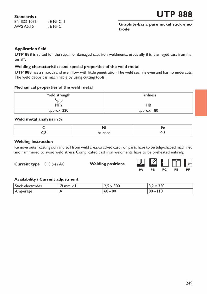
249
Graphite-basic pure nickel stick elec-trode
UTP 888
Welding instructionRemove outer casting skin and soil from weld area. Cracked cast iron parts have to be tulip-shaped machinedand hammered to avoid weld stress. Complicated cast iron weldments have to be preheated entirely.
Availability / Current adjustment
Current type DC (–) / AC
Application fieldUTP 888 is suited for the repair of damaged cast iron weldments, especially if it is an aged cast iron ma-terial”.Welding characteristics and special properties of the weld metalUTP 888 has a smooth and even flow with little penetration. The weld seam is even and has no undercuts.The weld deposit is machinable by using cutting tools.
Weld metal analysis in %
Mechanical properties of the weld metal
Standards :EN ISO 1071 : E Ni-Cl 1AWS A5.15 : E Ni-Cl
Yield strengthRp0,2MPaapprox. 220
HardnessHB
approx. 180
C0,8
Nibalance
Fe0,5
Stick electrodesAmperage
Ø mm x LA
2,5 x 30060 – 80
3,2 x 35080 – 110
Welding positionsPA PB PC PE PF
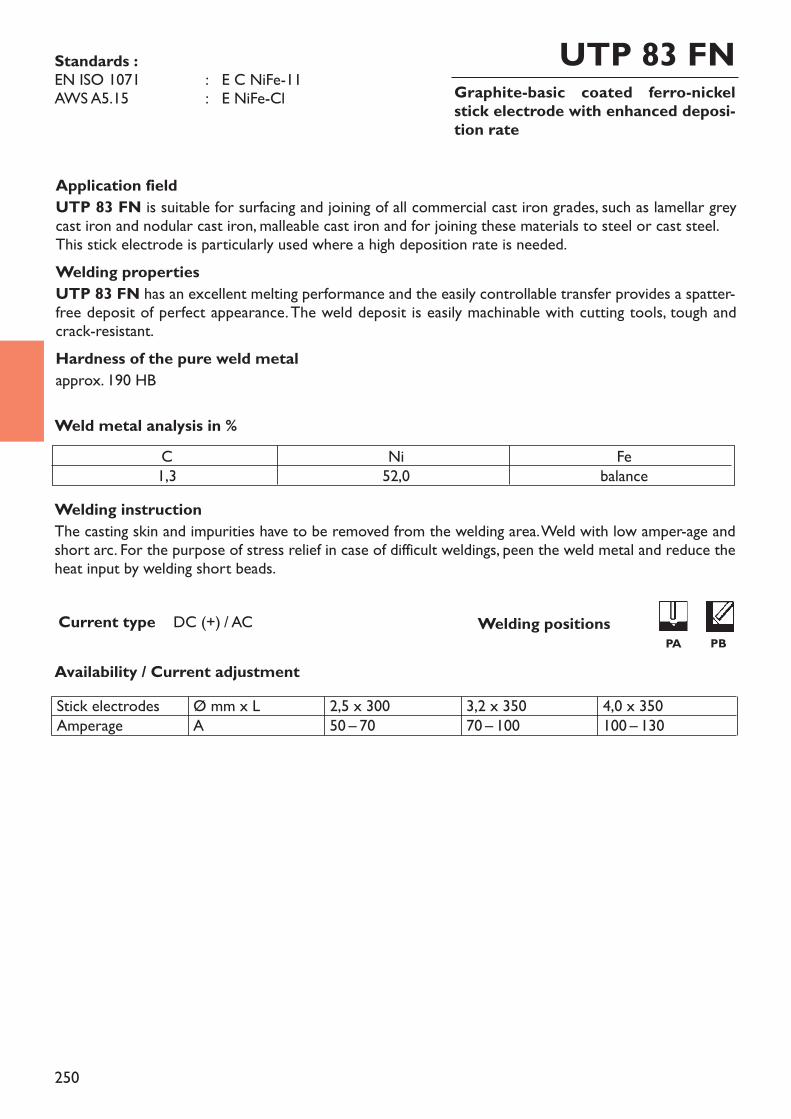
250
Graphite-basic coated ferro-nickelstick electrode with enhanced deposi-tion rate
UTP 83 FN
Welding instructionThe casting skin and impurities have to be removed from the welding area. Weld with low amper-age andshort arc. For the purpose of stress relief in case of difficult weldings, peen the weld metal and reduce theheat input by welding short beads.
Availability / Current adjustment
Current type DC (+) / AC
Application fieldUTP 83 FN is suitable for surfacing and joining of all commercial cast iron grades, such as lamellar greycast iron and nodular cast iron, malleable cast iron and for joining these materials to steel or cast steel.This stick electrode is particularly used where a high deposition rate is needed.Welding propertiesUTP 83 FN has an excellent melting performance and the easily controllable transfer provides a spatter-free deposit of perfect appearance. The weld deposit is easily machinable with cutting tools, tough andcrack-resistant.Hardness of the pure weld metalapprox. 190 HB
Weld metal analysis in %
Standards :EN ISO 1071 : E C NiFe-11AWS A5.15 : E NiFe-Cl
C1,3
Ni52,0
Febalance
Stick electrodesAmperage
Ø mm x LA
2,5 x 30050 – 70
3,2 x 35070 – 100
4,0 x 350100 – 130
Welding positionsPA PB
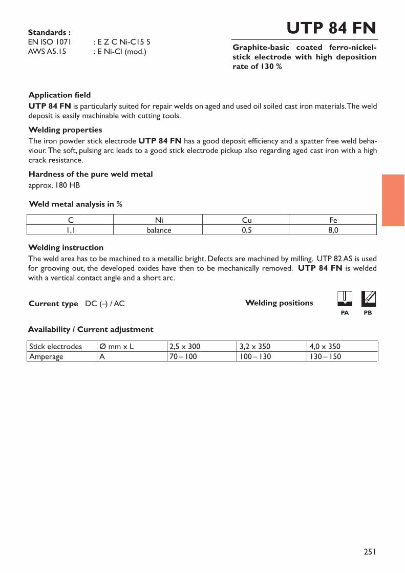
251
Graphite-basic coated ferro-nickel-stick electrode with high depositionrate of 130 %
UTP 84 FN
Welding instructionThe weld area has to be machined to a metallic bright. Defects are machined by milling. UTP 82 AS is usedfor grooving out, the developed oxides have then to be mechanically removed. UTP 84 FN is weldedwith a vertical contact angle and a short arc.
Availability / Current adjustment
Current type DC (–) / AC
Application fieldUTP 84 FN is particularly suited for repair welds on aged and used oil soiled cast iron materials. The welddeposit is easily machinable with cutting tools.Welding propertiesThe iron powder stick electrode UTP 84 FN has a good deposit efficiency and a spatter free weld beha-viour. The soft, pulsing arc leads to a good stick electrode pickup also regarding aged cast iron with a highcrack resistance.Hardness of the pure weld metalapprox. 180 HBWeld metal analysis in %
Standards :EN ISO 1071 : E Z C Ni-C15 5AWS A5.15 : E Ni-Cl (mod.)
C1,1
Nibalance
Cu0,5
Fe8,0
Stick electrodesAmperage
Ø mm x LA
2,5 x 30070 – 100
3,2 x 350100 – 130
4,0 x 350130 – 150
Welding positionsPA PB
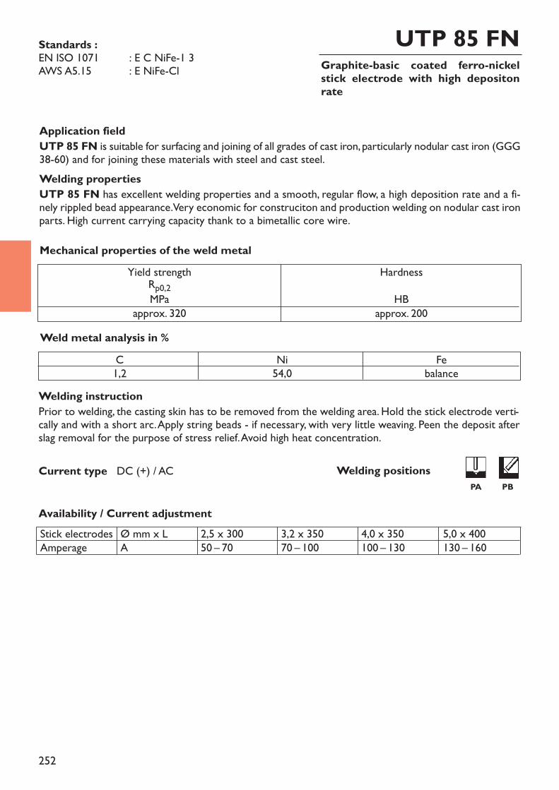
252
Graphite-basic coated ferro-nickelstick electrode with high depositonrate
UTP 85 FN
Welding instructionPrior to welding, the casting skin has to be removed from the welding area. Hold the stick electrode verti-cally and with a short arc. Apply string beads - if necessary, with very little weaving. Peen the deposit afterslag removal for the purpose of stress relief. Avoid high heat concentration.
Availability / Current adjustment
Current type DC (+) / AC
Application fieldUTP 85 FN is suitable for surfacing and joining of all grades of cast iron, particularly nodular cast iron (GGG38-60) and for joining these materials with steel and cast steel.Welding propertiesUTP 85 FN has excellent welding properties and a smooth, regular flow, a high deposition rate and a fi-nely rippled bead appearance. Very economic for construciton and production welding on nodular cast ironparts. High current carrying capacity thank to a bimetallic core wire.
Weld metal analysis in %
Mechanical properties of the weld metal
Standards :EN ISO 1071 : E C NiFe-1 3AWS A5.15 : E NiFe-Cl
Yield strengthRp0,2MPaapprox. 320
HardnessHB
approx. 200
C1,2
Ni54,0
Febalance
Stick electrodesAmperage
Ø mm x LA
2,5 x 30050 – 70
3,2 x 35070 – 100
4,0 x 350100 – 130
5,0 x 400130 – 160
Welding positionsPA PB

253
Graphite-basic coated ferro-nickelstick electrode with high mechanical values for repair and construction
UTP 86 FN
Welding instructionUTP 86 FN is preferably welded on DC (negative polarity) or on AC. When welding on DC (neg. po-la-rity), a deep penetration is reached (advantage for fillet welds). Positional weldings are easier with AC. Priorto welding, remove the casting skin. Hold stick electrode vertically and with short arc. When welding crack-suscepible cast iron grades, the deposit may be peened for the purpose of stress relief.
Application fieldUTP 86 FN is suitable for joining and surfacing of lamellar grey cast iron GG 10 - GG 40, nodular cast iron(spheroidal cast iron) GGG 40 - GGG 70 and malleable cast iron grades GTS 35 - GTS 65 as well as forjoining these materials with each other or with steel and cast steel. Universally applicable for repair, con-struction and production welding.Welding propertiesUTP 86 FN has excellent buttering characteristics on cast iron. The stick electrode has a stable arc andproduces a flat seam structure without undercutting. Particularly for fillet welds an optimal seam structureis achieved (e.g. welding GGG-flanges or sockets to GGG-tubes). Due to the bimetallic core wire, the cur-rent carrying capacity and the deposition rate are excellent. The bead appearance is smooth. The weld de-posit is highly crack resistant and easily machinable with cutting tools.
Weld metal analysis in %
Mechanical properties of the weld metal
Standards :EN ISO 1071 : E C NiFe-13AWS A5.15 : E NiFe-Cl
Yield strengthRp0,2MPaapprox. 340
HardnessHB
approx. 220
C1,2
Nibalance
Fe45,0
ApprovalsDB (No. 62.138.05)
Availability / Current adjustmentsStick electrodesAmperage
Ø mm x LA
2,5 x 30060 – 90
3,2 x 35090 – 140
4,0 x 350100 – 170
Current type = – ~ Welding positionsPA PB PC PE PF
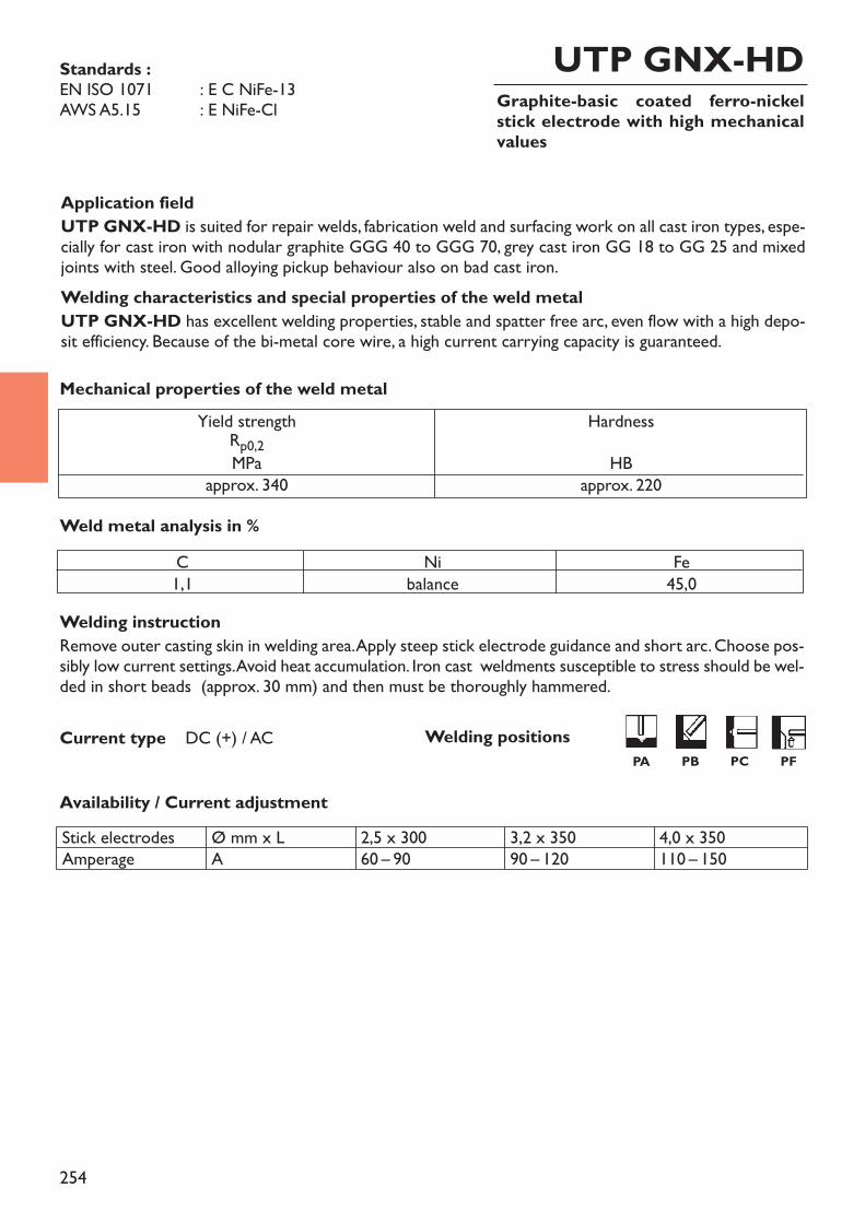
254
Graphite-basic coated ferro-nickelstick electrode with high mechanicalvalues
UTP GNX-HD
Welding instructionRemove outer casting skin in welding area. Apply steep stick electrode guidance and short arc. Choose pos-sibly low current settings. Avoid heat accumulation. Iron cast weldments susceptible to stress should be wel-ded in short beads (approx. 30 mm) and then must be thoroughly hammered.
Availability / Current adjustment
Current type DC (+) / AC
Application fieldUTP GNX-HD is suited for repair welds, fabrication weld and surfacing work on all cast iron types, espe-cially for cast iron with nodular graphite GGG 40 to GGG 70, grey cast iron GG 18 to GG 25 and mixedjoints with steel. Good alloying pickup behaviour also on bad cast iron.Welding characteristics and special properties of the weld metalUTP GNX-HD has excellent welding properties, stable and spatter free arc, even flow with a high depo-sit efficiency. Because of the bi-metal core wire, a high current carrying capacity is guaranteed.
Weld metal analysis in %
Mechanical properties of the weld metal
Standards :EN ISO 1071 : E C NiFe-13AWS A5.15 : E NiFe-Cl
Yield strengthRp0,2MPaapprox. 340
HardnessHB
approx. 220
C1,1
Nibalance
Fe45,0
Stick electrodesAmperage
Ø mm x LA
2,5 x 30060 – 90
3,2 x 35090 – 120
4,0 x 350110 – 150
Welding positionsPA PB PC PF
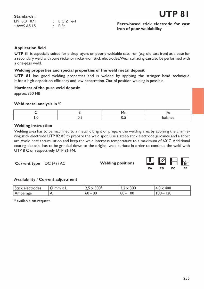
255
Ferro-based stick electrode for castiron of poor weldability
UTP 81
Welding instructionWelding area has to be machined to a metallic bright or prepare the welding area by applying the chamfe-ring stick electrode UTP 82 AS to prepare the weld spot. Use a steep stick electrode guidance and a shortarc. Avoid heat accumulation and keep the weld interpass temperature to a maximum of 60°C. Additionalcoating deposit has to be grinded down to the original weld surface in order to continue the weld withUTP 8 C or respectively UTP 86 FN.
* available on request
Availability / Current adjustment
Current type DC (+) / AC
Application fieldUTP 81 is especially suited for pickup layers on poorly weldable cast iron (e.g. old cast iron) as a base fora secondary weld with pure nickel or nickel-iron stick electrodes. Wear surfacing can also be performed witha one-pass weld.Welding properties and special properties of the weld metal depositUTP 81 has good welding properties and is welded by applying the stringer bead technique. It has a high deposition efficiency and low penetration. Out of position welding is possible. Hardness of the pure weld depositapprox. 350 HBWeld metal analysis in %
Standards :EN ISO 1071 : E C Z Fe-1~AWS A5.15 : E St
C1,0
Si0,5
Mn0,5
Febalance
Stick electrodesAmperage
Ø mm x LA
2,5 x 300*60 – 80
3,2 x 30080 – 100
4,0 x 400100 – 120
Welding positionsPA PB PC PF
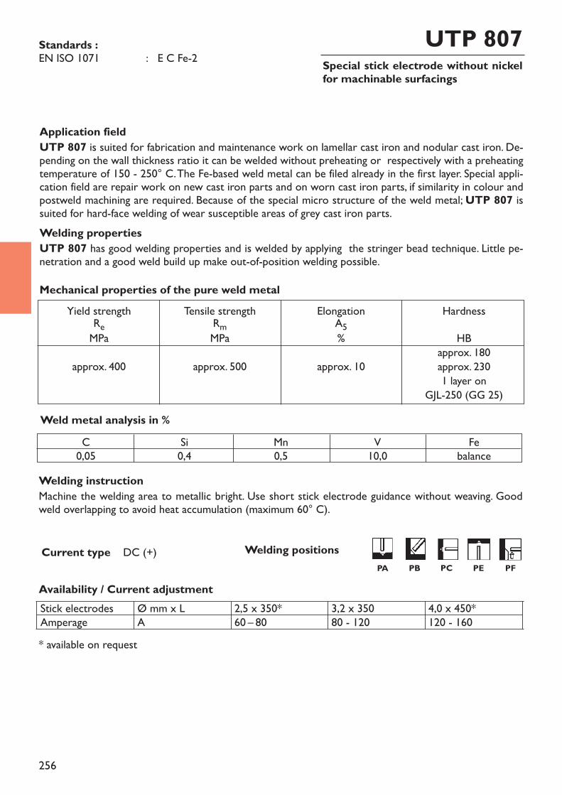
256
Special stick electrode without nickelfor machinable surfacings
UTP 807
Welding instructionMachine the welding area to metallic bright. Use short stick electrode guidance without weaving. Goodweld overlapping to avoid heat accumulation (maximum 60° C).
* available on request
Availability / Current adjustment
Current type DC (+)
Application fieldUTP 807 is suited for fabrication and maintenance work on lamellar cast iron and nodular cast iron. De-pending on the wall thickness ratio it can be welded without preheating or respectively with a preheatingtemperature of 150 - 250° C. The Fe-based weld metal can be filed already in the first layer. Special appli-cation field are repair work on new cast iron parts and on worn cast iron parts, if similarity in colour andpostweld machining are required. Because of the special micro structure of the weld metal; UTP 807 issuited for hard-face welding of wear susceptible areas of grey cast iron parts. Welding propertiesUTP 807 has good welding properties and is welded by applying the stringer bead technique. Little pe-netration and a good weld build up make out-of-position welding possible.
Weld metal analysis in %
Yield strengthReMPaapprox. 400
Tensile strengthRmMPaapprox. 500
ElongationA5%approx. 10
HardnessHB
approx. 180approx. 2301 layer on
GJL-250 (GG 25)
Mechanical properties of the pure weld metal
Standards :EN ISO 1071 : E C Fe-2
C0,05
Si0,4
Mn0,5
V10,0
Febalance
Stick electrodesAmperage
Ø mm x LA
2,5 x 350*60 – 80
3,2 x 35080 - 120
4,0 x 450*120 - 160
Welding positionsPA PB PC PE PF
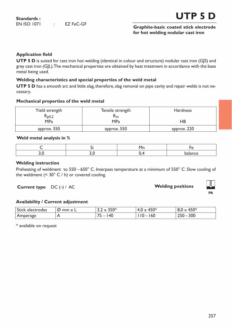
257
Graphite-basic coated stick electrodefor hot welding nodular cast iron
UTP 5 D
Welding instructionPreheating of weldment to 550 – 650° C. Interpass temperature at a minimum of 550° C. Slow cooling ofthe weldment (< 30° C / h) or covered cooling.
* available on request
Availability / Current adjustment
Current type DC (–) / AC
Application fieldUTP 5 D is suited for cast iron hot welding (identical in colour and structure) nodular cast iron (GJS) andgrey cast iron (GJL). The mechanical properties are obtained by heat treatment in accordance with the basemetal being used. Welding characteristics and special properties of the weld metalUTP 5 D has a smooth arc and little slag, therefore, slag removal on pipe cavity and repair welds is not ne-cessary.
Weld metal analysis in %
Mechanical properties of the weld metal
Standards :EN ISO 1071 : EZ FeC-GF
Yield strengthRp0,2MPa
Tensile strengthRmMPa
HardnessHB
approx. 350 approx. 550 approx. 220
C3,0
Si3,0
Mn0,4
Febalance
Stick electrodesAmperage
Ø mm x LA
3,2 x 350*75 – 140
4,0 x 450*110 – 160
8,0 x 450*250 – 300
Welding positionsPA
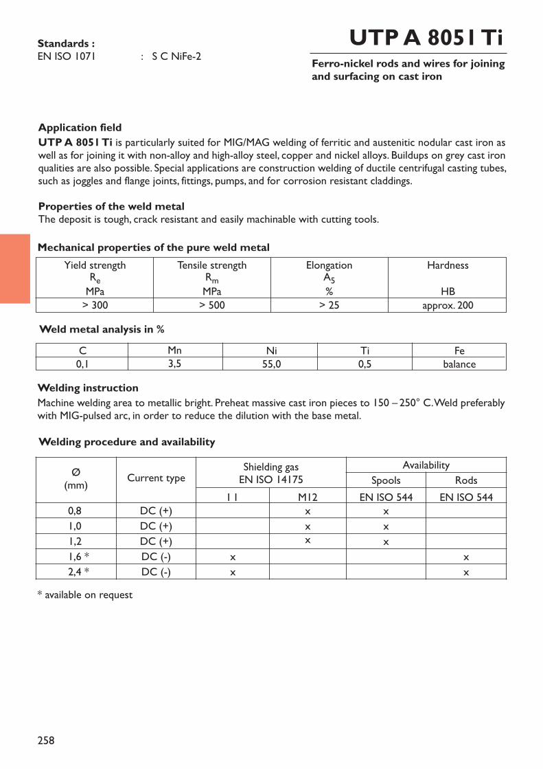
258
Ferro-nickel rods and wires for joiningand surfacing on cast iron
UTP A 8051 Ti
Application fieldUTP A 8051 Ti is particularly suited for MIG/MAG welding of ferritic and austenitic nodular cast iron aswell as for joining it with non-alloy and high-alloy steel, copper and nickel alloys. Buildups on grey cast ironqualities are also possible. Special applications are construction welding of ductile centrifugal casting tubes,such as joggles and flange joints, fittings, pumps, and for corrosion resistant claddings. Properties of the weld metalThe deposit is tough, crack resistant and easily machinable with cutting tools.
Welding instructionMachine welding area to metallic bright. Preheat massive cast iron pieces to 150 – 250° C. Weld preferablywith MIG-pulsed arc, in order to reduce the dilution with the base metal.
Weld metal analysis in %
* available on request
Yield strengthReMPa> 300
Tensile strengthRmMPa> 500
ElongationA5%> 25
HardnessHB
approx. 200
Mechanical properties of the pure weld metal
Standards :EN ISO 1071 : S C NiFe-2
C0,1
Mn3,5
Ni55,0
Ti0,5
Febalance
Welding procedure and availability
Ø(mm) Current type Shielding gas
EN ISO 14175Availability
Spools RodsI 1 M12 EN ISO 544 EN ISO 544
0,8 DC (+) x x1,0 DC (+) x x1,2 DC (+) x x1,6 * DC (-) x x2,4 * DC (-) x x
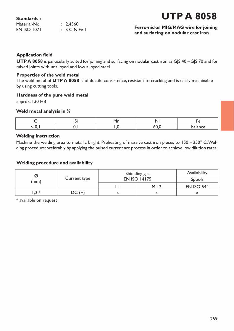
259
Ferro-nickel MIG/MAG wire for joiningand surfacing on nodular cast iron
UTP A 8058
Application fieldUTP A 8058 is particularly suited for joining and surfacing on nodular cast iron as GJS 40 –GJS 70 and formixed joints with unalloyed and low alloyed steel. Properties of the weld metalThe weld metal of UTP A 8058 is of ductile consistence, resistant to cracking and is easily machinableby using cutting tools.Hardness of the pure weld metalapprox. 130 HB
Welding instructionMachine the welding area to metallic bright. Preheating of massive cast iron pieces to 150 – 250° C. Wel-ding procedure: preferably by applying the pulsed current arc process in order to achieve low dilution rates.
Weld metal analysis in %
Standards :Material-No. : 2.4560EN ISO 1071 : S C NIFe-1
C< 0,1
Si0,1
Mn1,0
Ni60,0
Febalance
* available on request
Welding procedure and availability
Ø(mm) Current type Shielding gas
EN ISO 14175AvailabilitySpools
I 1 M 12 EN ISO 5441,2 * DC (+) x x x
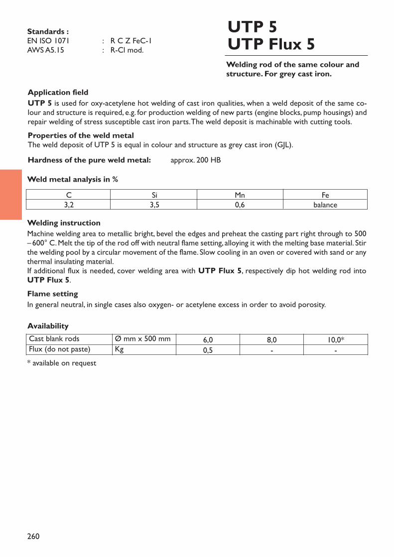
260
Welding rod of the same colour andstructure. For grey cast iron.
UTP 5UTP Flux 5
Application fieldUTP 5 is used for oxy-acetylene hot welding of cast iron qualities, when a weld deposit of the same co-lour and structure is required, e.g. for production welding of new parts (engine blocks, pump housings) andrepair welding of stress susceptible cast iron parts. The weld deposit is machinable with cutting tools.Properties of the weld metalThe weld deposit of UTP 5 is equal in colour and structure as grey cast iron (GJL).Hardness of the pure weld metal: approx. 200 HB
Welding instructionMachine welding area to metallic bright, bevel the edges and preheat the casting part right through to 500–600° C. Melt the tip of the rod off with neutral flame setting, alloying it with the melting base material. Stirthe welding pool by a circular movement of the flame. Slow cooling in an oven or covered with sand or anythermal insulating material.If additional flux is needed, cover welding area with UTP Flux 5, respectively dip hot welding rod into UTP Flux 5.Flame settingIn general neutral, in single cases also oxygen- or acetylene excess in order to avoid porosity.
Weld metal analysis in %
Standards :EN ISO 1071 : R C Z FeC-1AWS A5.15 : R-Cl mod.
C3,2
Si3,5
Mn0,6
Febalance
Cast blank rods Ø mm x 500 mm 6,0 8,0 10,0*Flux (do not paste) Kg 0,5 - -
Availability
* available on request
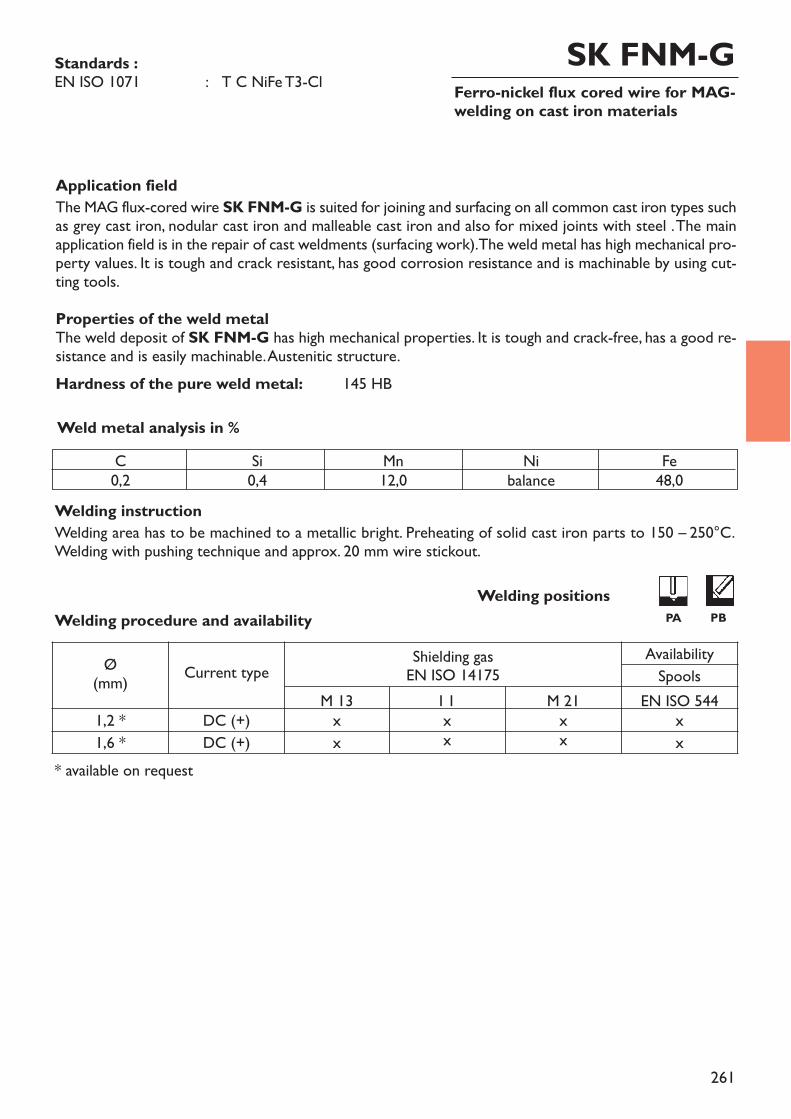
261
Ferro-nickel flux cored wire for MAG-welding on cast iron materials
Application fieldThe MAG flux-cored wire SK FNM-G is suited for joining and surfacing on all common cast iron types suchas grey cast iron, nodular cast iron and malleable cast iron and also for mixed joints with steel . The mainapplication field is in the repair of cast weldments (surfacing work). The weld metal has high mechanical pro-perty values. It is tough and crack resistant, has good corrosion resistance and is machinable by using cut-ting tools.Properties of the weld metalThe weld deposit of SK FNM-G has high mechanical properties. It is tough and crack-free, has a good re-sistance and is easily machinable. Austenitic structure.Hardness of the pure weld metal: 145 HB
Welding instructionWelding area has to be machined to a metallic bright. Preheating of solid cast iron parts to 150 – 250°C.Welding with pushing technique and approx. 20 mm wire stickout.
Weld metal analysis in %
* available on request
Standards :EN ISO 1071 : T C NiFe T3-Cl
SK FNM-G
Welding procedure and availabilityWelding positions
PA PB
C0,2
Si0,4
Mn12,0
Nibalance
Fe48,0
Ø(mm) Current type Shielding gas
EN ISO 14175AvailabilitySpools
M 13 I 1 M 21 EN ISO 5441,2 * DC (+) x x x x1,6 * DC (+) x x x x

262
263
Index
Welding consumables for copper and copper alloys
stick electrodessolid rods and wires
Group 5Welding consumablesfor copper and copperalloys

264
Welding consumables for copper and copper alloys
stick electrodessolid rods and wires
271 - 279280 - 294
page xxx
Group 5Welding consumablesfor copper and copperalloys
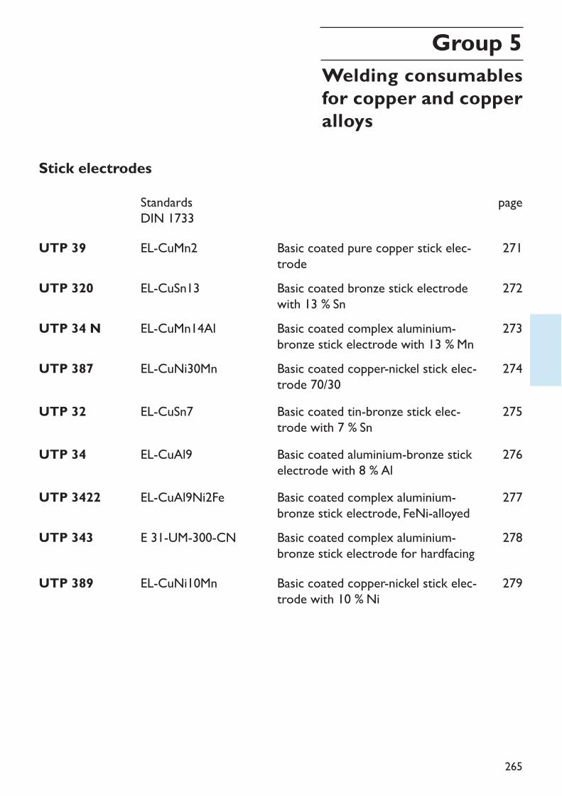
265
Stick electrodesStandardsDIN 1733
UTP 3422 EL-CuAl9Ni2Fe Basic coated complex aluminium-bronze stick electrode, FeNi-alloyed
page
277
UTP 343 E 31-UM-300-CN Basic coated complex aluminium-bronze stick electrode for hardfacing
278
UTP 389 EL-CuNi10Mn Basic coated copper-nickel stick elec-trode with 10 % Ni
279
UTP 39 EL-CuMn2 Basic coated pure copper stick elec-trode
UTP 320 EL-CuSn13 Basic coated bronze stick electrodewith 13 % Sn
UTP 34 N EL-CuMn14Al Basic coated complex aluminium-bronze stick electrode with 13 % Mn
271
272
273
UTP 32 EL-CuSn7 Basic coated tin-bronze stick elec-trode with 7 % Sn
275
UTP 387 EL-CuNi30Mn Basic coated copper-nickel stick elec-trode 70/30
274
UTP 34 EL-CuAl9 Basic coated aluminium-bronze stickelectrode with 8 % Al
276
Group 5Welding consumablesfor copper and copperalloys
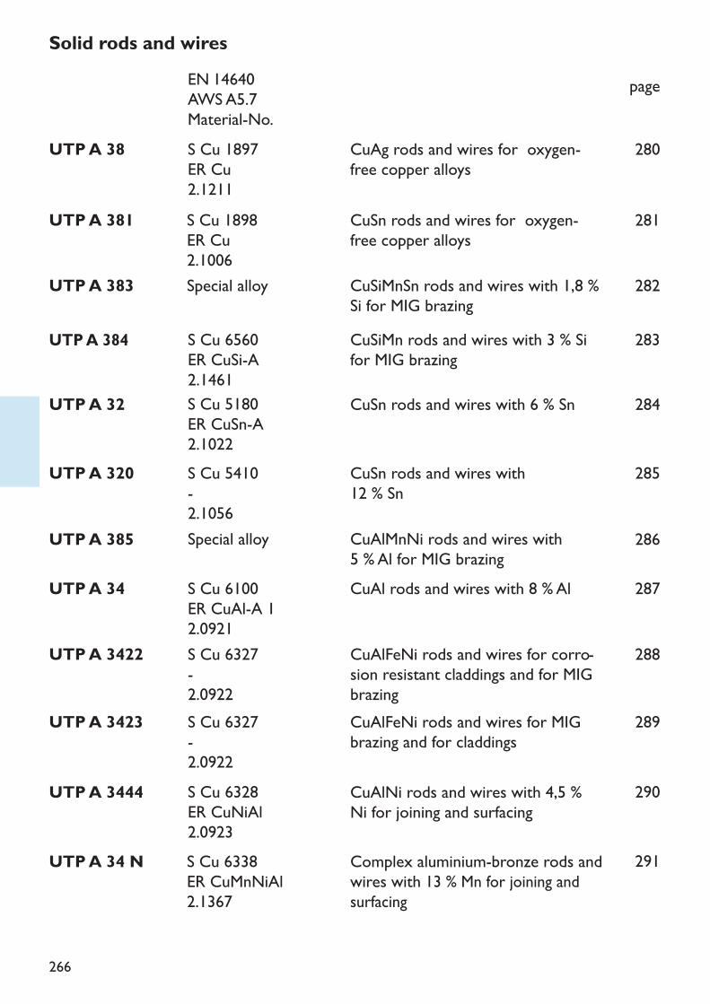
266
UTP A 38 CuAg rods and wires for oxygen-free copper alloys
280
UTP A 381 CuSn rods and wires for oxygen-free copper alloysCuSiMnSn rods and wires with 1,8 %Si for MIG brazing
281
UTP A 384 CuSiMn rods and wires with 3 % Sifor MIG brazing
283
UTP A 32 CuSn rods and wires with 6 % Sn 284
Solid rods and wirespage
UTP A 383
UTP A 320 CuSn rods and wires with 12 % Sn
282
UTP A 3423 289
285
UTP A 385 CuAlMnNi rods and wires with 5 % Al for MIG brazing
286
UTP A 3422 CuAlFeNi rods and wires for corro-sion resistant claddings and for MIGbrazingCuAlFeNi rods and wires for MIGbrazing and for claddings
288
UTP A 34 CuAl rods and wires with 8 % Al 287
S Cu 1897ER Cu2.1211S Cu 1898ER Cu2.1006
S Cu 6560ER CuSi-A2.1461S Cu 5180ER CuSn-A2.1022
EN 14640AWS A5.7Material-No.
Special alloy
S Cu 5410-2.1056
S Cu 6327-2.0922
Special alloy
S Cu 6327-2.0922
S Cu 6100ER CuAl-A 12.0921
S Cu 6328ER CuNiAl2.0923S Cu 6338ER CuMnNiAl2.1367
UTP A 3444 CuAlNi rods and wires with 4,5 %Ni for joining and surfacing
290
UTP A 34 N Complex aluminium-bronze rods andwires with 13 % Mn for joining andsurfacing
291
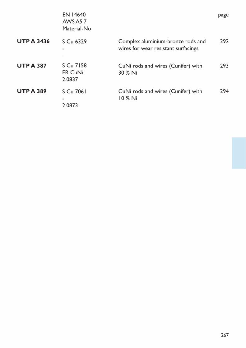
267
page
UTP A 387 CuNi rods and wires (Cunifer) with30 % Ni
293
UTP A 389 CuNi rods and wires (Cunifer) with10 % Ni
294
UTP A 3436 Complex aluminium-bronze rods andwires for wear resistant surfacings
292
EN 14640AWS A5.7Material-No
S Cu 7158ER CuNi2.0837S Cu 7061-2.0873
S Cu 6329--
268
CopperUTP 39, UTP A 381, UTP A 38For welding jobs, oxygen free copper according to DIN 1787 (e. g. SF–Cu, SW–Cu and OF–Cu)should be selected since these qualities have the best performance. Of particular importance arethe high heat conductibility, the high heat expansion, the tendency to attract gases when liquidand to release these gases again when solidifying.Depending on the size of the part to be welded, the pre-heating temperature of 300 – 700° Cmay be needed. Such a pre-heating temperature should be maintained during the welding pro-cess. The welding with shielding gas is protecting the weld pool better than oxy-acetylene wel-ding and reduces the tendency to porosity.Peening of the weld deposit while still hot increases the tensile strength and improves the duc-tility. On multi layer deposits, the oxide skin of the previous layer has to be removed before de-positing the next layer.
Copper-Zinc-alloys(brass, special brass ) DIN 17660, DIN 1709UTP 32 –UTP A 32, UTP 320 –UTP A 320, UTP 34 –UTP A 34,UTP A 34 MR, UTP A 384Due to zinc evaporation during welding, porosities in the welding deposit are nearly unavoida-ble.TIG welding should be done with lowest possible amperage, eventually with a.c. to obtain acleaning effect.For brass with Al addition, e. g. CuZn20Al (special brass 76) TIG welding (d. c.) with UTP A 34MR and for red brass (CuSnZnPb), TIG welding with UTP A 384 is particularly suitable.
Copper-Tin alloys(tin bronzes) DIN 17662, DIN 1705UTP 32 –UTP A 32, UTP 320 –UTP A 320Beside the welding with coated stick electrodes, the MIG/TIG welding is particularly suitable forthis alloy group.The low heat conductibility requests a pre-heating from a wall thickness of > 10 mm only. Thetendency to pores is low. Mechanical properties and corrosion resistance correspond with theidentical base material.For joining thick walled parts it is an advantage to weld from both sides simultaneously.
The welding of copper and copper alloys
269
Copper-Aluminium alloys (aluminium bronzes, complex aluminium bronzes) DIN 17665UTP 34 –UTP A 34, UTP 34 N –UTP A 34 N, UTP 3422 –UTP A 3422, UTP A 3444, UTP Flux 34 SpRegarding welding process, the coated stick electrodes and the MIG/TIG welding are suitable forthis alloy group.When TIG welding with d. c. the UTP Flux 34 Sp is needed to destroy the tough aluminiumoxide skin. Due to this it is possible to use a low amperage, which in turn reduces the danger ofpores and intercristalline failure.For wall thickness > 6 mm the MIG welding procedure may be advantageous. The joint areamust be metallic blank, to prevent pores and cracks. Pre-heating is needed for wall thickness >10 mm only.
Copper-Nickel alloys DIN 17658UTP 389 –UTP A 389, UTP 387 –UTP A 387Copper-nickel alloys with or without Fe addition are easy weldable.Welding can be done by coated stick electrode or by MIG/TIG process. A low heat input and,consequently, a small dilution with the base metal is an advantage.When MIG welding, overheating and heat accumlation have to be avoided. It is an advantage touse MIG pulse procedure with a 1.2 mm wire. Oxides and other impurities must be removedfrom the weld area.For mixed joints with steel we recommend to use UTP 80 M* or UTP A 80 M*.* nickel-copper alloy
270
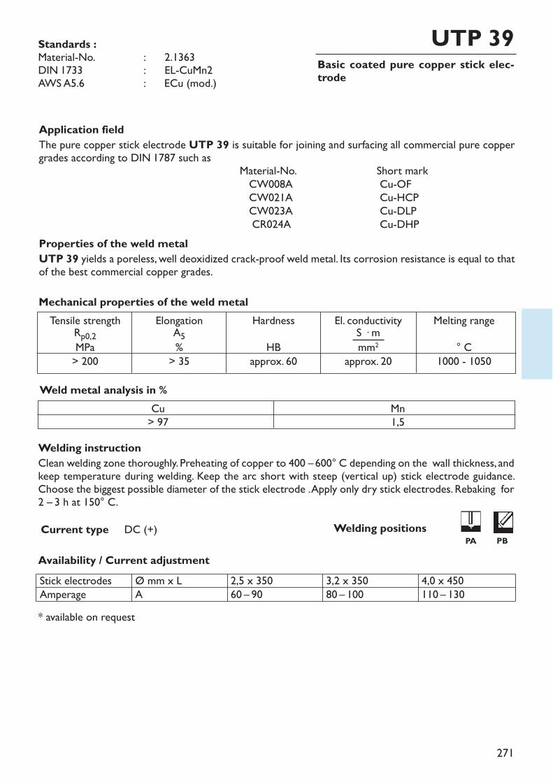
271
Basic coated pure copper stick elec-trode
UTP 39
Welding instructionClean welding zone thoroughly. Preheating of copper to 400 –600° C depending on the wall thickness, andkeep temperature during welding. Keep the arc short with steep (vertical up) stick electrode guidance.Choose the biggest possible diameter of the stick electrode . Apply only dry stick electrodes. Rebaking for2 – 3 h at 150° C.
Availability / Current adjustment
Current type DC (+)
Application fieldThe pure copper stick electrode UTP 39 is suitable for joining and surfacing all commercial pure coppergrades according to DIN 1787 such as
Material-No. Short markCW008A Cu-OFCW021A Cu-HCPCW023A Cu-DLPCR024A Cu-DHP
Properties of the weld metalUTP 39 yields a poreless, well deoxidized crack-proof weld metal. Its corrosion resistance is equal to thatof the best commercial copper grades.
Weld metal analysis in %Cu> 97
Mn1,5
Tensile strengthRp0,2MPa> 200
ElongationA5%> 35
HardnessHB
approx. 60
El. conductivityS � mmm2
approx. 20
Melting range° C
1000 - 1050
Mechanical properties of the weld metal
* available on request
Standards :Material-No. : ~ 2.1363DIN 1733 : ~ EL-CuMn2AWS A5.6 : ECu (mod.)
Stick electrodesAmperage
Ø mm x LA
2,5 x 35060 – 90
3,2 x 35080 – 100
4,0 x 450110 – 130
Welding positionsPA PB
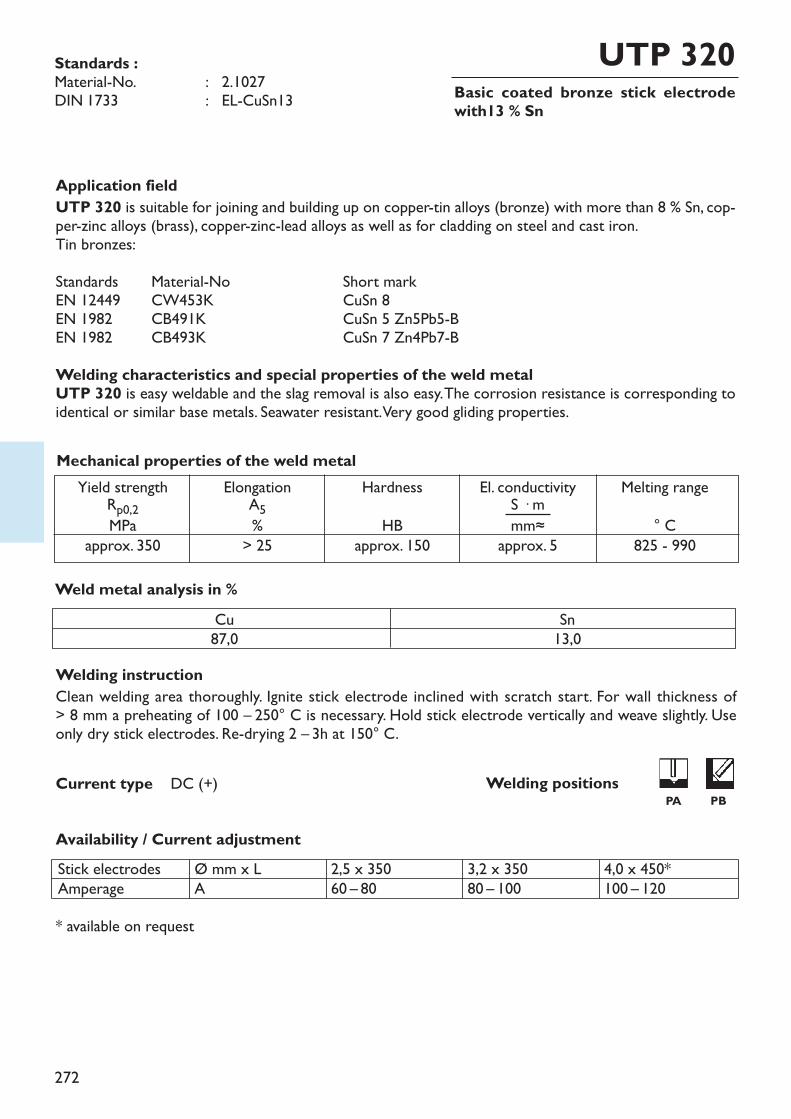
272
Basic coated bronze stick electrodewith13 % Sn
UTP 320
Welding instructionClean welding area thoroughly. Ignite stick electrode inclined with scratch start. For wall thickness of > 8 mm a preheating of 100 – 250° C is necessary. Hold stick electrode vertically and weave slightly. Useonly dry stick electrodes. Re-drying 2 – 3h at 150° C.
Availability / Current adjustment
Current type DC (+)
Application fieldUTP 320 is suitable for joining and building up on copper-tin alloys (bronze) with more than 8 % Sn, cop-per-zinc alloys (brass), copper-zinc-lead alloys as well as for cladding on steel and cast iron.Tin bronzes:Standards Material-No Short markEN 12449 CW453K CuSn 8EN 1982 CB491K CuSn 5 Zn5Pb5-BEN 1982 CB493K CuSn 7 Zn4Pb7-BWelding characteristics and special properties of the weld metalUTP 320 is easy weldable and the slag removal is also easy. The corrosion resistance is corresponding toidentical or similar base metals. Seawater resistant. Very good gliding properties.
Weld metal analysis in %
Yield strengthRp0,2MPaapprox. 350
ElongationA5%> 25
HardnessHB
approx. 150
El. conductivityS � mmm≈
approx. 5
Melting range° C
825 - 990
Mechanical properties of the weld metal
* available on request
Standards :Material-No. : 2.1027DIN 1733 : EL-CuSn13
Cu87,0
Sn13,0
Stick electrodesAmperage
Ø mm x LA
2,5 x 35060 – 80
3,2 x 35080 – 100
4,0 x 450*100 – 120
Welding positionsPA PB
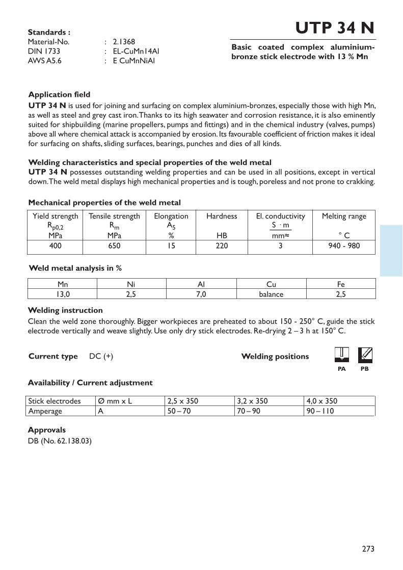
273
Basic coated complex aluminium-bronze stick electrode with 13 % Mn
UTP 34 N
Welding instructionClean the weld zone thoroughly. Bigger workpieces are preheated to about 150 - 250° C, guide the stickelectrode vertically and weave slightly. Use only dry stick electrodes. Re-drying 2 – 3 h at 150° C.
Availability / Current adjustment
Current type DC (+)
Application fieldUTP 34 N is used for joining and surfacing on complex aluminium-bronzes, especially those with high Mn,as well as steel and grey cast iron. Thanks to its high seawater and corrosion resistance, it is also eminentlysuited for shipbuilding (marine propellers, pumps and fittings) and in the chemical industry (valves, pumps)above all where chemical attack is accompanied by erosion. Its favourable coefficient of friction makes it idealfor surfacing on shafts, sliding surfaces, bearings, punches and dies of all kinds.Welding characteristics and special properties of the weld metalUTP 34 N possesses outstanding welding properties and can be used in all positions, except in verticaldown. The weld metal displays high mechanical properties and is tough, poreless and not prone to crakking.
Weld metal analysis in %
Yield strengthRp0,2MPa400
Tensile strengthRmMPa650
ElongationA5%15
HardnessHB220
El. conductivityS � mmm≈3
Melting range° C
940 - 980
Mechanical properties of the weld metal
Standards :Material-No. : 2.1368DIN 1733 : EL-CuMn14AlAWS A5.6 : E CuMnNiAl
Mn13,0
Ni2,5
Al7,0
Cubalance
Fe2,5
Stick electrodesAmperage
Ø mm x LA
2,5 x 35050 – 70
3,2 x 35070 – 90
4,0 x 35090 – 110
ApprovalsDB (No. 62.138.03)
Welding positions PA PB
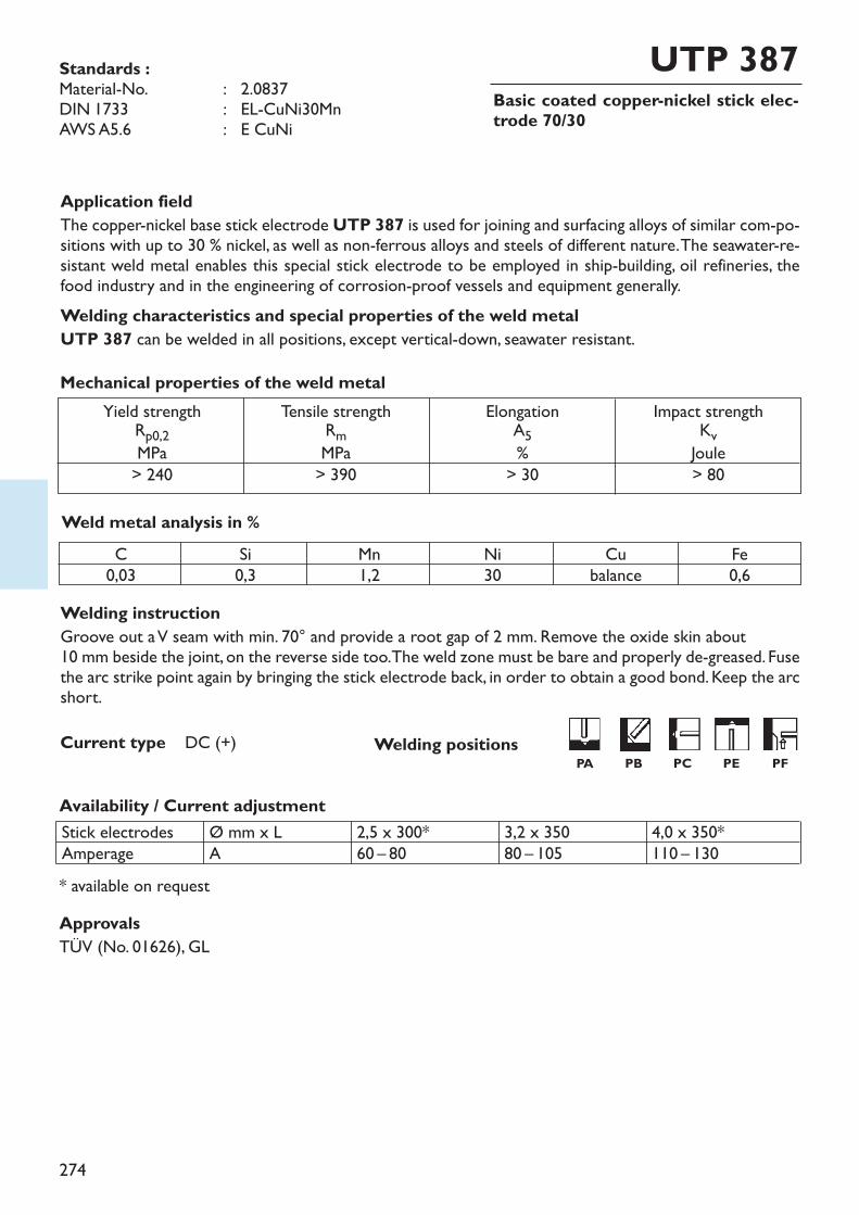
274
Basic coated copper-nickel stick elec-trode 70/30
UTP 387
Welding instructionGroove out a V seam with min. 70° and provide a root gap of 2 mm. Remove the oxide skin about 10 mm beside the joint, on the reverse side too. The weld zone must be bare and properly de-greased. Fusethe arc strike point again by bringing the stick electrode back, in order to obtain a good bond. Keep the arcshort.
Availability / Current adjustment
Application fieldThe copper-nickel base stick electrode UTP 387 is used for joining and surfacing alloys of similar com-po-sitions with up to 30 % nickel, as well as non-ferrous alloys and steels of different nature. The seawater-re-sistant weld metal enables this special stick electrode to be employed in ship-building, oil refineries, thefood industry and in the engineering of corrosion-proof vessels and equipment generally.Welding characteristics and special properties of the weld metalUTP 387 can be welded in all positions, except vertical-down, seawater resistant.
Weld metal analysis in %
Yield strengthRp0,2MPa> 240
Tensile strengthRmMPa> 390
ElongationA5%> 30
Impact strengthKvJoule> 80
Mechanical properties of the weld metal
Current type DC (+)
* available on request
Standards :Material-No. : 2.0837DIN 1733 : EL-CuNi30MnAWS A5.6 : E CuNi
C0,03
Si0,3
Mn1,2
Ni30
Cubalance
Fe0,6
Stick electrodesAmperage
Ø mm x LA
2,5 x 300*60 – 80
3,2 x 35080 – 105
4,0 x 350*110 – 130
ApprovalsTÜV (No. 01626), GL
Welding positionsPA PB PC PE PF
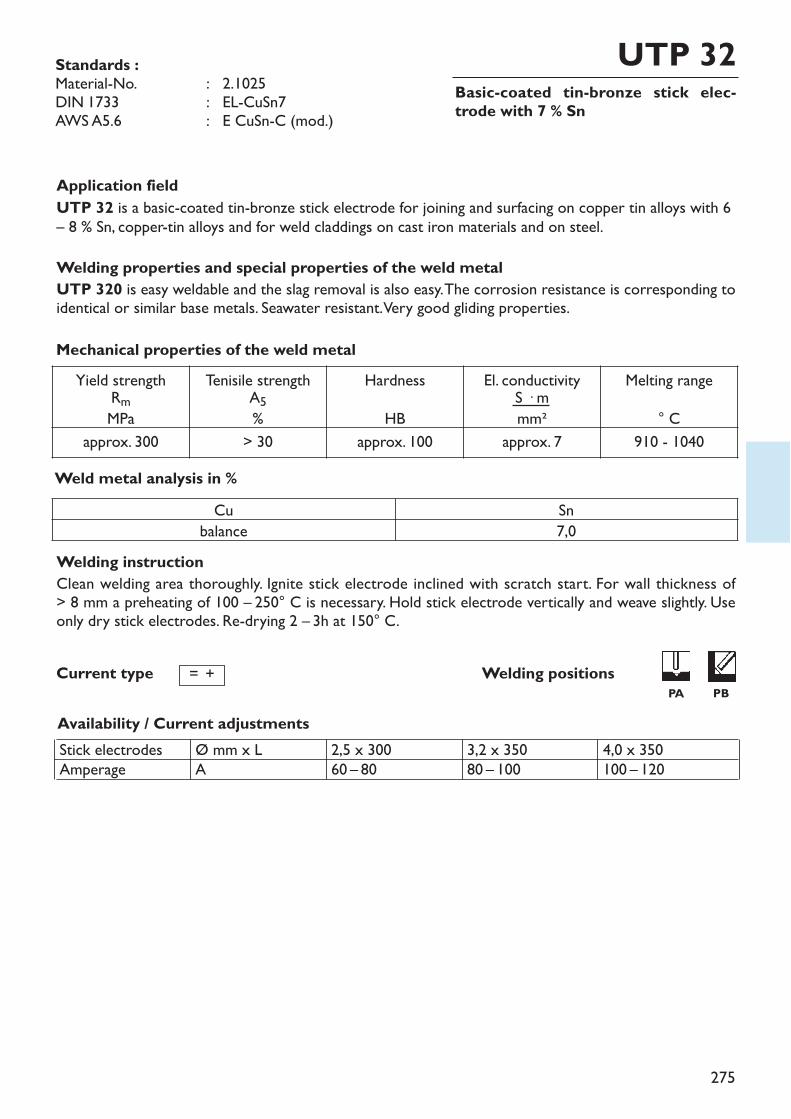
275
Basic-coated tin-bronze stick elec-trode with 7 % Sn
UTP 32
Welding instructionClean welding area thoroughly. Ignite stick electrode inclined with scratch start. For wall thickness of > 8 mm a preheating of 100 – 250° C is necessary. Hold stick electrode vertically and weave slightly. Useonly dry stick electrodes. Re-drying 2 – 3h at 150° C.
Availability / Current adjustments
Standards :Material-No. : 2.1025DIN 1733 : EL-CuSn7AWS A5.6 : E CuSn-C (mod.)
Application fieldUTP 32 is a basic-coated tin-bronze stick electrode for joining and surfacing on copper tin alloys with 6– 8 % Sn, copper-tin alloys and for weld claddings on cast iron materials and on steel.Welding properties and special properties of the weld metalUTP 320 is easy weldable and the slag removal is also easy. The corrosion resistance is corresponding toidentical or similar base metals. Seawater resistant. Very good gliding properties.
Weld metal analysis in %
Stick electrodesAmperage
Ø mm x LA
2,5 x 30060 – 80
3,2 x 35080 – 100
4,0 x 350100 – 120
Mechanical properties of the weld metal
Welding positionsCurrent type = +
Cu Snbalance 7,0
Yield strengthRmMPa
Tenisile strengthA5%
HardnessHB
El. conductivityS � mmm²
Melting range° C
approx. 300 > 30 approx. 100 approx. 7 910 - 1040
PA PB
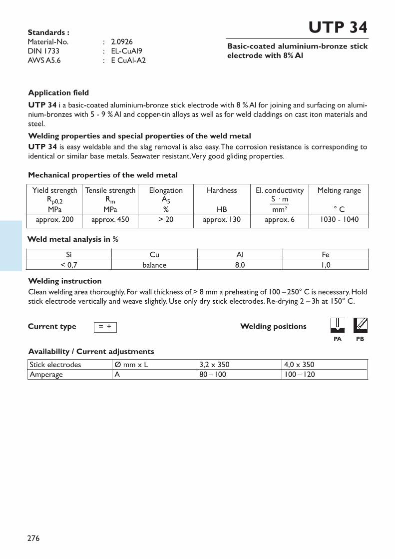
276
Basic-coated aluminium-bronze stickelectrode with 8% Al
UTP 34
Welding instructionClean welding area thoroughly. For wall thickness of > 8 mm a preheating of 100 –250° C is necessary. Holdstick electrode vertically and weave slightly. Use only dry stick electrodes. Re-drying 2 – 3h at 150° C.
Availability / Current adjustments
Standards :Material-No. : 2.0926DIN 1733 : EL-CuAl9AWS A5.6 : E CuAl-A2
Application fieldUTP 34 i a basic-coated aluminium-bronze stick electrode with 8 % Al for joining and surfacing on alumi-nium-bronzes with 5 - 9 % Al and copper-tin alloys as well as for weld claddings on cast iton materials andsteel.Welding properties and special properties of the weld metalUTP 34 is easy weldable and the slag removal is also easy. The corrosion resistance is corresponding toidentical or similar base metals. Seawater resistant. Very good gliding properties.
Weld metal analysis in %
Stick electrodesAmperage
Ø mm x LA
3,2 x 35080 – 100
4,0 x 350100 – 120
Mechanical properties of the weld metal
Welding positionsCurrent type = +
Yield strengthRp0,2MPaapprox. 200
Tensile strengthRmMPaapprox. 450
ElongationA5%> 20
HardnessHB
approx. 130
El. conductivityS � mmm²
approx. 6
Melting range° C
1030 - 1040
Si Cu Al Fe< 0,7 balance 8,0 1,0
PA PB
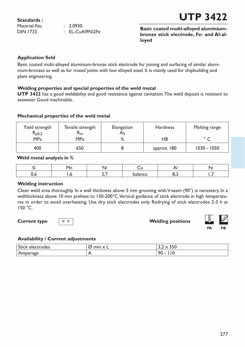
277
Basic coated multi-alloyed aluminium-bronze stick electrode, Fe- and Al-al-loyed
UTP 3422
Welding instructionClean weld area thoroughly. In a wall thickness above 5 mm grooving with V-seam (90°) is necessary. In awallthickness above 10 mm preheat to 150-200°C. Vertical guidance of stick electrode in high temperatu-res in order to avoid overheating. Use dry stick electrodes only. Redrying of stick electrodes 2-3 h at 150 °C.
Availability / Current adjustments
Standards :Material-No. : 2.0930DIN 1733 : EL-CuAl9Ni2Fe
Application fieldBasic coated multi-alloyed aluminium-bronze stick electrode for joining and surfacing of similar alumi-nium-bronzes as well as for mixed joints with low alloyed steel. It is mainly used for shipbuilding andplant engineering.Welding properties and special properties of the weld metalUTP 3422 has a good weldability and good resistance against cavitation. The weld deposit is resistant toseawater. Good machinable.
Weld metal analysis in %
Stick electrodesAmperage
Ø mm x LA
3,2 x 35090 - 110
Mechanical properties of the weld metal
Welding positionsCurrent type = +
Si Mn Ni Cu Al Fe0,6 1,6 2,7 balance 8,3 1,7
Yield strengthRp0,2MPa
Tensile strengthRmMPa
ElongationA5%
HardnessHB
Melting range° C
400 650 8 approx. 180 1030 - 1050
PA PB
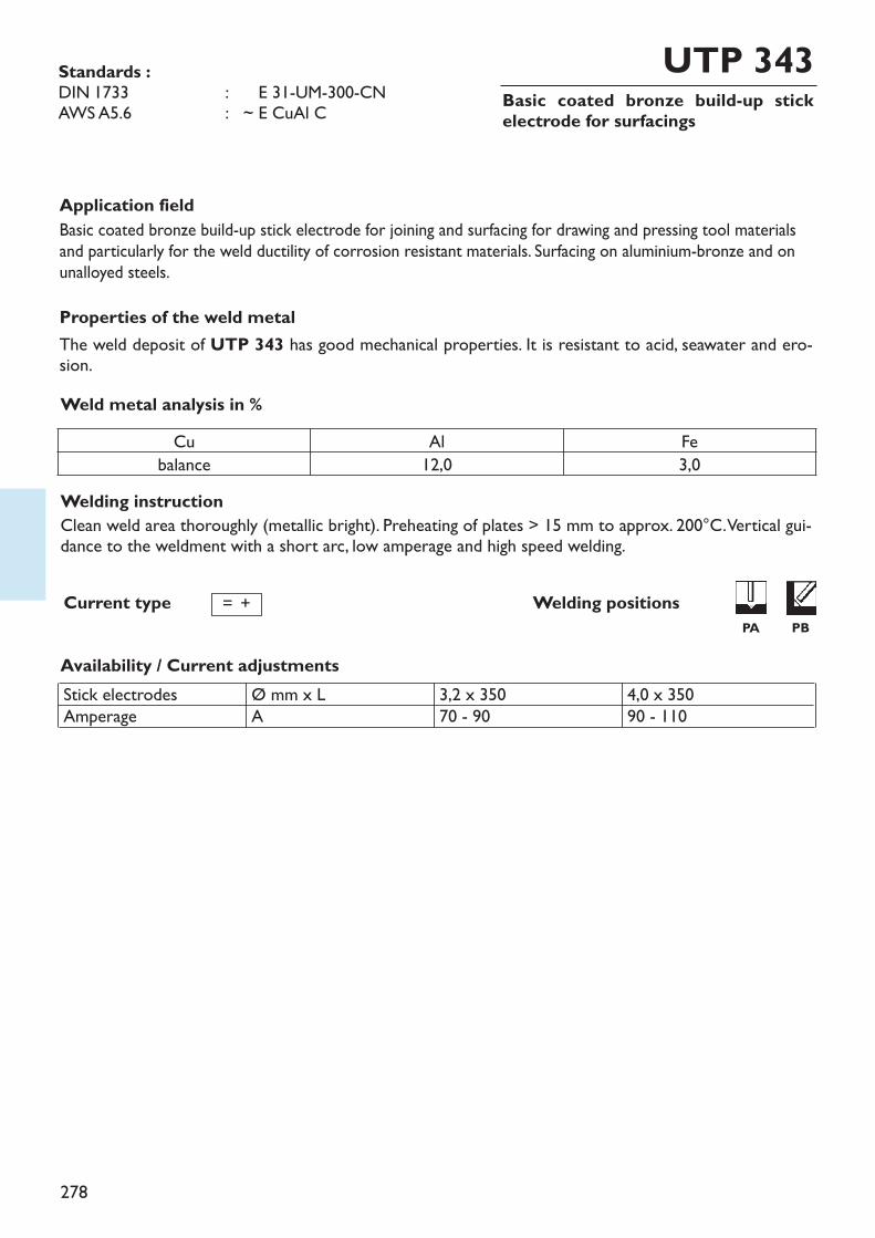
278
Basic coated bronze build-up stickelectrode for surfacings
UTP 343
Welding instructionClean weld area thoroughly (metallic bright). Preheating of plates > 15 mm to approx. 200°C. Vertical gui-dance to the weldment with a short arc, low amperage and high speed welding.
Availability / Current adjustments
Standards :DIN 1733 : ~ E 31-UM-300-CNAWS A5.6 : ~ E CuAl C
Application fieldBasic coated bronze build-up stick electrode for joining and surfacing for drawing and pressing tool materialsand particularly for the weld ductility of corrosion resistant materials. Surfacing on aluminium-bronze and onunalloyed steels.Properties of the weld metalThe weld deposit of UTP 343 has good mechanical properties. It is resistant to acid, seawater and ero-sion.Weld metal analysis in %
Stick electrodesAmperage
Ø mm x LA
3,2 x 35070 - 90
4,0 x 35090 - 110
Welding positionsCurrent type = +
Cu Al Febalance 12,0 3,0
PA PB
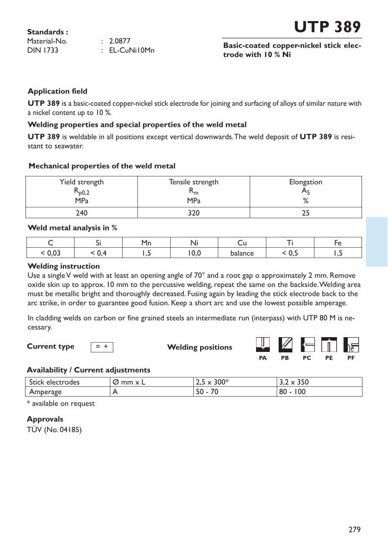
279
Basic-coated copper-nickel stick elec-trode with 10 % Ni
UTP 389
Welding instructionUse a single V weld with at least an opening angle of 70° and a root gap o approximately 2 mm. Removeoxide skin up to approx. 10 mm to the percussive welding, repeat the same on the backside. Welding areamust be metallic bright and thoroughly decreased. Fusing again by leading the stick electrode back to thearc strike, in order to guarantee good fusion. Keep a short arc and use the lowest possible amperage.In cladding welds on carbon or fine grained steels an intermediate run (interpass) with UTP 80 M is ne-cessary.
Availability / Current adjustments
Standards :Material-No. : 2.0877DIN 1733 : EL-CuNi10Mn
Application fieldUTP 389 is a basic-coated copper-nickel stick electrode for joining and surfacing of alloys of similar nature witha nickel content up to 10 %. Welding properties and special properties of the weld metalUTP 389 is weldable in all positions except vertical downwards. The weld deposit of UTP 389 is resi-stant to seawater.
Weld metal analysis in %
Stick electrodesAmperage
Ø mm x LA
2,5 x 300*50 - 70
3,2 x 35080 - 100
Mechanical properties of the weld metal
Current type = +
C Si Mn Ni Cu Ti Fe< 0,03 < 0,4 1,5 10,0 balance < 0,5 1,5
Approvals TÜV (No. 04185)
* available on request
Yield strengthRp0,2MPa
Tensile strengthRmMPa
ElongationA5%
240 320 25
Welding positionsPA PB PC PE PF
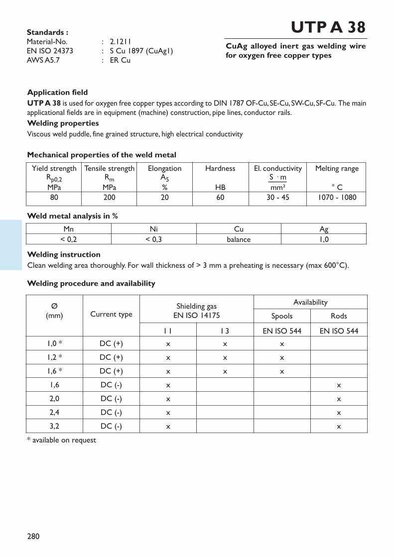
280
CuAg alloyed inert gas welding wirefor oxygen free copper types
Application fieldUTP A 38 is used for oxygen free copper types according to DIN 1787 OF-Cu, SE-Cu, SW-Cu, SF-Cu. The mainapplicational fields are in equipment (machine) construction, pipe lines, conductor rails. Welding propertiesViscous weld puddle, fine grained structure, high electrical conductivity
Welding instructionClean welding area thoroughly. For wall thickness of > 3 mm a preheating is necessary (max 600°C).
Weld metal analysis in %
Standards :Material-No. : 2.1211EN ISO 24373 : S Cu 1897 (CuAg1)AWS A5.7 : ER Cu
UTP A 38
Mechanical properties of the weld metalYield strengthRp0,2MPa
80
Tensile strengthRmMPa200
ElongationA5%20
HardnessHB60
El. conductivityS � mmm²
30 - 45
Melting range° C
1070 - 1080
Mn Ni Cu Ag< 0,2 < 0,3 balance 1,0
Ø(mm) Current type Shielding gas
EN ISO 14175Availability
Spools RodsI 1 I 3 EN ISO 544 EN ISO 544
1,0 * DC (+) x x x1,2 * DC (+) x x x1,6 * DC (+) x x x1,6 DC (-) x x2,0 DC (-) x x2,4 DC (-) x x3,2 DC (-) x x
Welding procedure and availability
* available on request
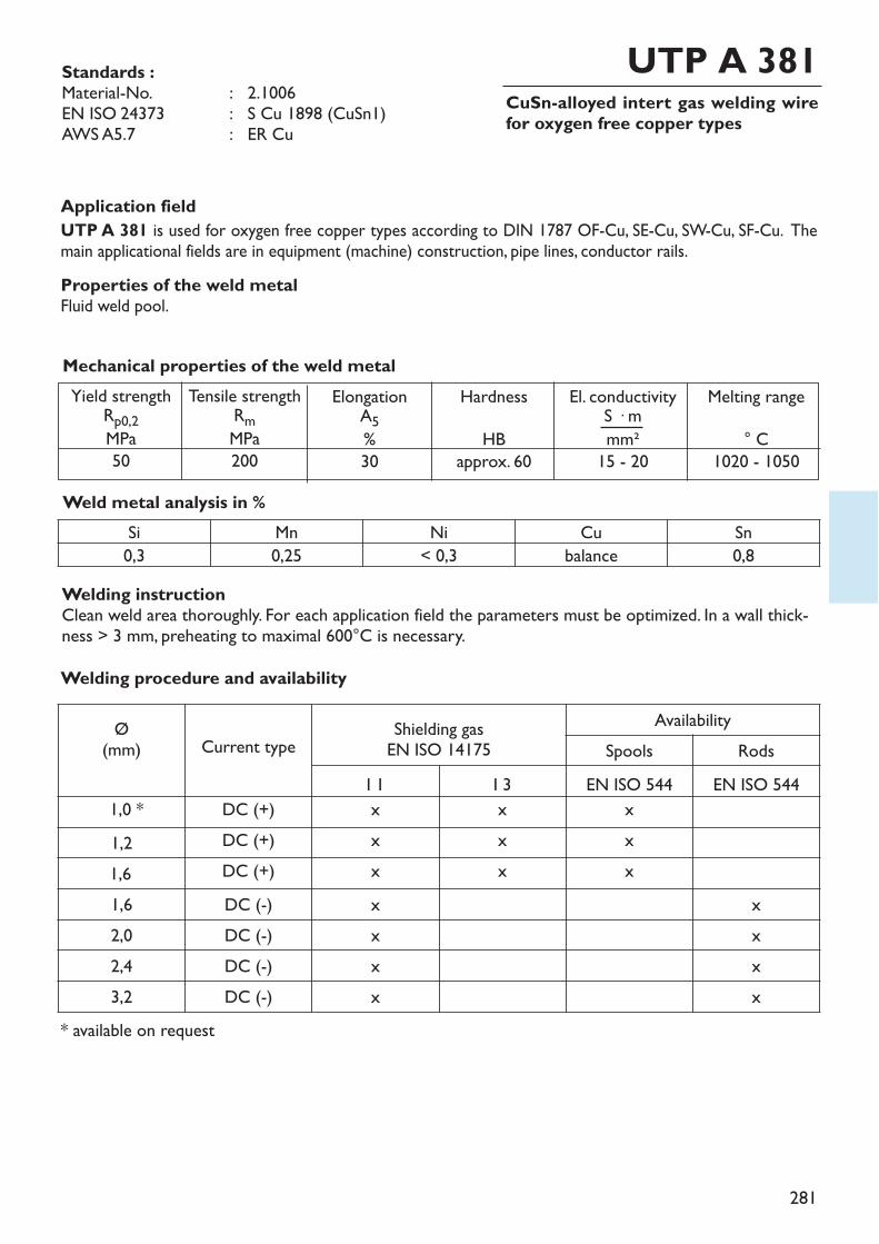
281
CuSn-alloyed intert gas welding wirefor oxygen free copper types
Application fieldUTP A 381 is used for oxygen free copper types according to DIN 1787 OF-Cu, SE-Cu, SW-Cu, SF-Cu. Themain applicational fields are in equipment (machine) construction, pipe lines, conductor rails.Properties of the weld metalFluid weld pool.
Welding instructionClean weld area thoroughly. For each application field the parameters must be optimized. In a wall thick-ness > 3 mm, preheating to maximal 600°C is necessary.
Weld metal analysis in %
Standards :Material-No. : 2.1006EN ISO 24373 : S Cu 1898 (CuSn1)AWS A5.7 : ER Cu
UTP A 381
Mechanical properties of the weld metalYield strengthRp0,2MPa
50
Tensile strengthRmMPa200
ElongationA5%30
HardnessHB
approx. 60
El. conductivityS � mmm²
15 - 20
Melting range° C
1020 - 1050
Si Mn Ni Cu Sn0,3 0,25 < 0,3 balance 0,8
Ø(mm) Current type Shielding gas
EN ISO 14175Availability
Spools RodsI 1 I 3 EN ISO 544 EN ISO 544
1,0 * DC (+) x x x1,2 DC (+) x x x1,6 DC (+) x x x1,6 DC (-) x x2,0 DC (-) x x2,4 DC (-) x x3,2 DC (-) x x
Welding procedure and availability
* available on request
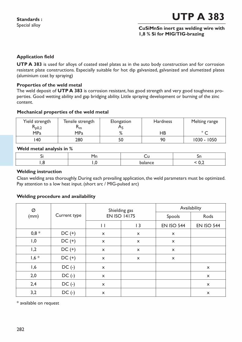
282
CuSiMnSn inert gas welding wire with1,8 % Si for MIG/TIG-brazing
Application fieldUTP A 383 is used for alloys of coated steel plates as in the auto body construction and for corrosionresistant plate constructions. Especially suitable for hot dip galvanized, galvanized and alumetized plates(aluminium coat by spraying)Properties of the weld metalThe weld deposit of UTP A 383 is corrosion resistant, has good strength and very good toughness pro-perties. Good wetting ability and gap bridging ability. Little spraying development or burning of the zinccontent.
Welding instructionClean welding area thoroughly. During each prevailing application, the weld parameters must be optimized.Pay attention to a low heat input. (short arc / MIG-pulsed arc)
Weld metal analysis in %
Standards :Special alloy
UTP A 383
Mechanical properties of the weld metal
Si Mn Cu Sn1,8 1,0 balance < 0,2
Ø(mm) Current type Shielding gas
EN ISO 14175Availability
Spools RodsI 1 I 3 EN ISO 544 EN ISO 544
0,8 * DC (+) x x x1,0 DC (+) x x x1,2 DC (+) x x x1,6 * DC (+) x x x1,6 DC (-) x x2,0 DC (-) x x2,4 DC (-) x x3,2 DC (-) x x
Welding procedure and availability
* available on request
Yield strengthRp0,2MPa
Tensile strengthRmMPa
ElongationA5%
HardnessHB
Melting range° C
140 280 50 90 1030 - 1050

283
CuSiMn-alloyed welding wire with 3 %Si for MIG-brazing
Application fieldUTP A 384 is especially suited for joints of coated steel plates according to the MIG welding for repairwelding of motor vehicle bodies and plate constructions of all sorts. The alloy is also especially suited forhot galvanized and hot dip galvanized plates. Same joints on copper-silicon and copper-manganese alloys ac-cording to DIN 1766, as for example CuSi2Mn, CuSi3Mn, CuMn5, brass and red brass (tombac).Properties of the weld metalThe low hardness of UTP A 384 allows a relatively easy machining of the visible weld seam in compari-son to the iron base weld metal. The corrosion protection of galvanized surfaces is kept mainly.
Welding instructionClean weld area thoroughly. Welding parameters have to be optimised for each usage. Pay attention to a lowheat input. (short arc / MIG pulsed arc)
Weld metal analysis in %
Standards :Material-No. : 2.1461EN ISO 24373 : S Cu 6560 (CuSi3Mn1)AWS A5.7 : ER CuSi-A
UTP A 384
Mechanical properties of the weld metalYield strengthRp0,2MPa
120
Tensile strengthRmMPa350
ElongationA5%40
HardnessHB80
El. conductivityS � mmm²3 - 4
Melting range° C
965 - 1035
Si Mn Cu Sn Fe3,0 1,0 balance < 0,2 < 0,3
Ø(mm) Current type Shielding gas
EN ISO 14175Availability
Spools RodsI 1 I 3 EN ISO 544 EN ISO 544
0,8 * DC (+) x x x1,0 DC (+) x x x1,2 DC (+) x x x1,6 * DC (+) x x x1,6 DC (-) x x2,0 DC (-) x x2,4 DC (-) x x3,2 DC (-) x x
Welding procedure and availability
* available on request
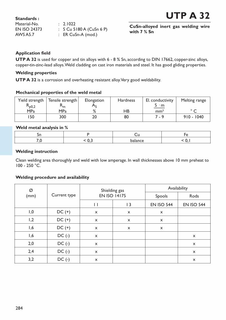
284
CuSn-alloyed inert gas welding wirewith 7 % Sn
Application fieldUTP A 32 is used for copper and tin alloys with 6 - 8 % Sn, according to DIN 17662, copper-zinc alloys,copper-tin-zinc-lead alloys. Weld cladding on cast iron materials and steel. It has good gliding properties. Welding propertiesUTP A 32 is a corrosion and overheating resistant alloy. Very good weldability.
Welding instructionClean welding area thoroughly and weld with low amperage. In wall thicknesses above 10 mm preheat to100 - 250 °C.
Weld metal analysis in %
Standards :Material-No. : 2.1022EN ISO 24373 : S Cu 5180 A (CuSn 6 P)AWS A5.7 : ER CuSn-A (mod.)
UTP A 32
Mechanical properties of the weld metalYield strengthRp0,2MPa
150
Tensile strengthRmMPa300
ElongationA5%20
HardnessHB80
El. conductivityS � mmm²7 - 9
Melting range° C
910 - 1040
Sn P Cu Fe7,0 < 0,3 balance < 0,1
Ø(mm) Current type Shielding gas
EN ISO 14175Availability
Spools RodsI 1 I 3 EN ISO 544 EN ISO 544
1,0 DC (+) x x x1,2 DC (+) x x x1,6 DC (+) x x x1,6 DC (-) x x2,0 DC (-) x x2,4 DC (-) x x3,2 DC (-) x x
Welding procedure and availability
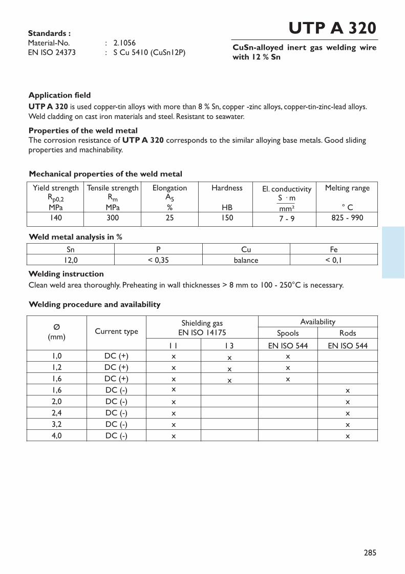
285
CuSn-alloyed inert gas welding wirewith 12 % Sn
Application fieldUTP A 320 is used copper-tin alloys with more than 8 % Sn, copper -zinc alloys, copper-tin-zinc-lead alloys.Weld cladding on cast iron materials and steel. Resistant to seawater.Properties of the weld metalThe corrosion resistance of UTP A 320 corresponds to the similar alloying base metals. Good slidingproperties and machinability.
Welding instructionClean weld area thoroughly. Preheating in wall thicknesses > 8 mm to 100 - 250°C is necessary.
Weld metal analysis in %
Standards :Material-No. : 2.1056EN ISO 24373 : S Cu 5410 (CuSn12P)
UTP A 320
Mechanical properties of the weld metalYield strengthRp0,2MPa
140
Tensile strengthRmMPa300
ElongationA5%25
HardnessHB150
Melting range° C
825 - 990
Sn P Cu Fe12,0 < 0,35 balance < 0,1
Welding procedure and availability
Ø(mm) Current type Shielding gas
EN ISO 14175Availability
Spools RodsI 1 I 3 EN ISO 544 EN ISO 544
1,0 DC (+) x x x1,2 DC (+) x x x1,6 DC (+) x x x1,6 DC (-) x x2,0 DC (-) x x2,4 DC (-) x x3,2 DC (-) x x4,0 DC (-) x x
El. conductivityS � mmm²7 - 9
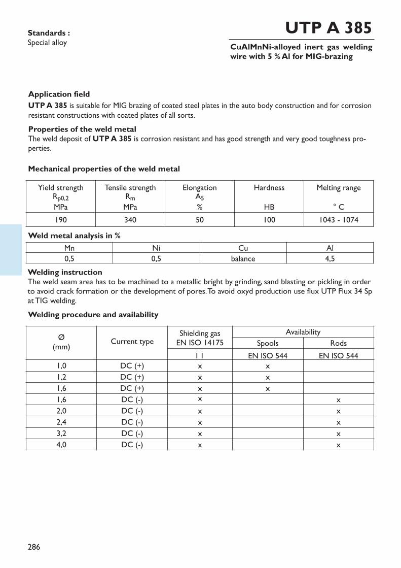
286
CuAlMnNi-alloyed inert gas weldingwire with 5 % Al for MIG-brazing
Application fieldUTP A 385 is suitable for MIG brazing of coated steel plates in the auto body construction and for corrosionresistant constructions with coated plates of all sorts.Properties of the weld metalThe weld deposit of UTP A 385 is corrosion resistant and has good strength and very good toughness pro-perties.
Welding instructionThe weld seam area has to be machined to a metallic bright by grinding, sand blasting or pickling in orderto avoid crack formation or the development of pores.To avoid oxyd production use flux UTP Flux 34 Spat TIG welding.
Weld metal analysis in %
Standards :Special alloy
UTP A 385
Mechanical properties of the weld metal
Mn Ni Cu Al0,5 0,5 balance 4,5
Welding procedure and availability
Yield strengthRp0,2MPa
Tensile strengthRmMPa
ElongationA5%
HardnessHB
Melting range° C
190 340 50 100 1043 - 1074
Ø(mm) Current type Shielding gas
EN ISO 14175Availability
Spools RodsI 1 EN ISO 544 EN ISO 544
1,0 DC (+) x x1,2 DC (+) x x1,6 DC (+) x x1,6 DC (-) x x2,0 DC (-) x x2,4 DC (-) x x3,2 DC (-) x x4,0 DC (-) x x

287
CuAl-alloyed inert gas welding wirewith 8 % Al
Application fieldUTP A 34 is used for copper aluminium alloys (aluminium bronzes) with 5 - 9 % Al, copper-zinc alloys (brassand special brass). Weld cladding on cast iron materials and steel.Properties of the weld metalThe weld deposit of UTP A 34 is resistant to corrosion and seawater and has good gliding propertiesmetal-metal. UTP A 34 is easy weldable and obtains a clean weld surface.
Welding instructionThe weld seam area has to be machined to a metallic bright by grinding, sand blasting or pickling in orderto avoid crack formation or the development of pores.To avoid oxyd production use flux UTP Flux 34 Spat TIG welding.
Weld metal analysis in %
Standards :Material-No. : 2.0921EN ISO 24373 : S Cu 6100 (CuAl7)AWS A5.7 : ER CuAl-A 1
UTP A 34
Mechanical properties of the weld metalYield strengthRp0,2MPa
180
Tensile strengthRmMPa400
ElongationA5%40
HardnessHB120
El. conductivityS � mmm²8
Melting range° C
1030 - 1040
Mn Ni Cu Al Fe< 0,5 < 0,5 balance 8,0 < 0,5
* available on requestApprovaksGL
Welding procedure and availability
Ø(mm) Current type Shielding gas
EN ISO 14175Availability
Spools RodsI 1 EN ISO 544 EN ISO 544
0,8 * DC (+) x x1,0 DC (+) x x1,2 DC (+) x x1,6 DC (+) x x1,6 DC (-) x x2,0 DC (-) x x2,4 DC (-) x x3,2 DC (-) x x
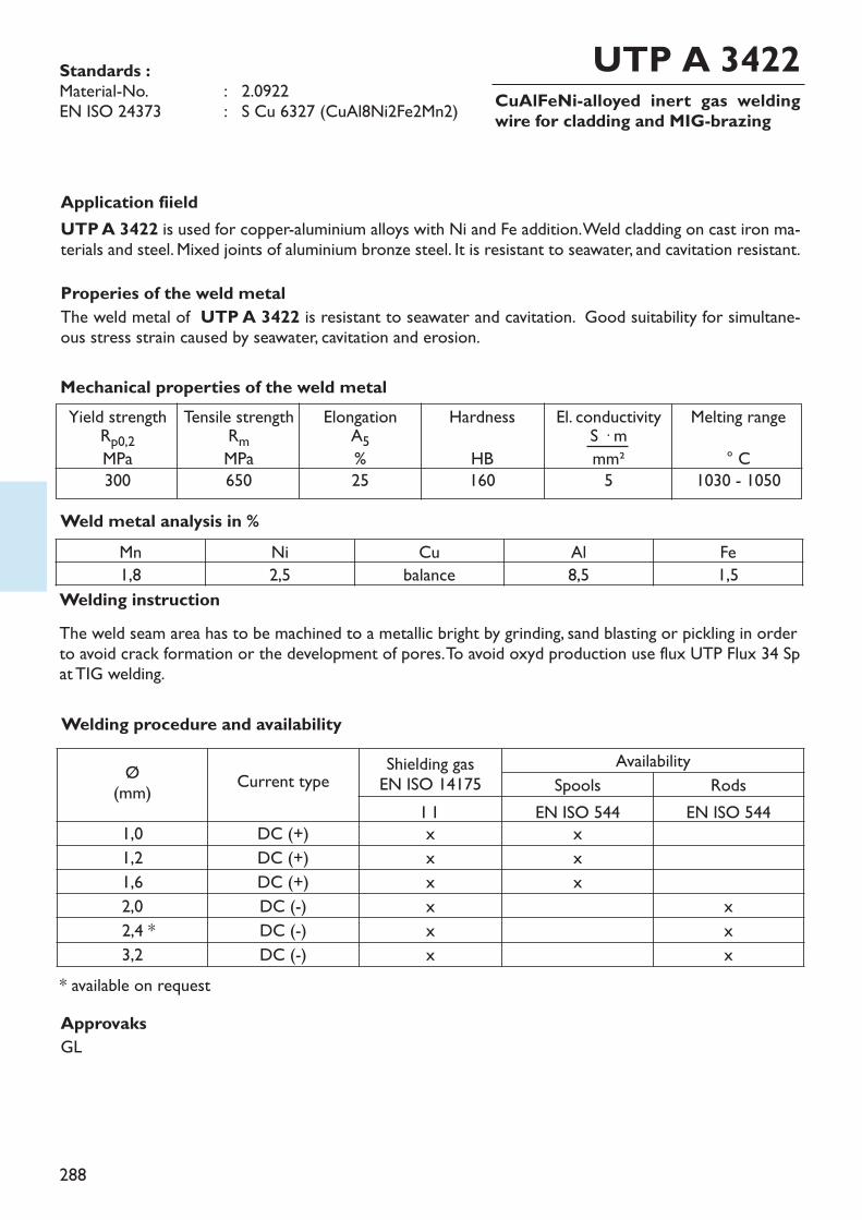
288
CuAlFeNi-alloyed inert gas weldingwire for cladding and MIG-brazing
Application fiieldUTP A 3422 is used for copper-aluminium alloys with Ni and Fe addition. Weld cladding on cast iron ma-terials and steel. Mixed joints of aluminium bronze steel. It is resistant to seawater, and cavitation resistant.Properies of the weld metalThe weld metal of UTP A 3422 is resistant to seawater and cavitation. Good suitability for simultane-ous stress strain caused by seawater, cavitation and erosion.
Welding instructionThe weld seam area has to be machined to a metallic bright by grinding, sand blasting or pickling in orderto avoid crack formation or the development of pores.To avoid oxyd production use flux UTP Flux 34 Spat TIG welding.
Weld metal analysis in %
Standards :Material-No. : 2.0922EN ISO 24373 : S Cu 6327 (CuAl8Ni2Fe2Mn2)
UTP A 3422
Mechanical properties of the weld metalYield strengthRp0,2MPa
300
Tensile strengthRmMPa650
ElongationA5%25
HardnessHB160
El. conductivityS � mmm²5
Melting range° C
1030 - 1050
Mn Ni Cu Al Fe1,8 2,5 balance 8,5 1,5
* available on requestApprovaksGL
Welding procedure and availability
Ø(mm) Current type Shielding gas
EN ISO 14175Availability
Spools RodsI 1 EN ISO 544 EN ISO 544
1,0 DC (+) x x1,2 DC (+) x x1,6 DC (+) x x2,0 DC (-) x x2,4 * DC (-) x x3,2 DC (-) x x

289
CuAlFeNi-alloyed welding wire forMIG-brazing and cladding
Application fieldUTP A 3423 is a CuAlFeNi shielded gas wire for MIG brazing and claddings on copper aluminium wroughtalloys according to DIN 17665, and cast multi aluminium bronzes according to DIN 1714, resistant to seawater. Properties of the weld metalThe weld metal of UTP A 3423 is resistant to seawater and cavitation. Good suitability for simultane-ous stress strain caused by seawater, cavitation and erosion.
Welding instructionThe weld seam area has to be machined to a metallic bright by grinding, sand blasting or pickling in orderto avoid crack formation or the development of pores.To avoid oxyd production use flux UTP Flux 34 Spat TIG welding.
Weld metal analysis in %
Standards :Material-No. : 2.0922EN ISO 24373 : S Cu 6327 (CuAl8Ni2Fe2Mn2)
UTP A 3423
Mechanical properties of the weld metalYield strengthRp0,2MPa
300
Tensile strengthRmMPa550
ElongationA5%25
HardnessHB160
El. conductivityS � mmm²5
Melting range° C
1030 - 1050
Mn Ni Cu Al Fe2,0 2,0 balance 8,0 2,0
* available on request
Welding procedure and availability
Ø(mm) Current type Shielding gas
EN ISO 14175Availability
Spools RodsI 1 EN ISO 544 EN ISO 544
1,0 DC (+) x x1,2 DC (+) x x1,6 DC (-) x x2,0 DC (-) x x2,4 * DC (-) x x3,2 DC (-) x x
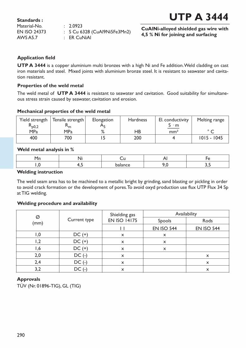
290
CuAlNi-alloyed shielded gas wire with4,5 % Ni for joining and surfacing
Application fieldUTP A 3444 is a copper aluminium multi bronzes with a high Ni and Fe addition. Weld cladding on castiron materials and steel. Mixed joints with aluminium bronze steel. It is resistant to seawater and cavita-tion resistant.Properties of the weld metalThe weld metal of UTP A 3444 is resistant to seawater and cavitation. Good suitability for simultane-ous stress strain caused by seawater, cavitation and erosion.
Welding instructionThe weld seam area has to be machined to a metallic bright by grinding, sand blasting or pickling in orderto avoid crack formation or the development of pores.To avoid oxyd production use flux UTP Flux 34 Spat TIG welding.
Weld metal analysis in %
Standards :Material-No. : 2.0923EN ISO 24373 : S Cu 6328 (CuAl9Ni5Fe3Mn2)AWS A5.7 : ER CuNiAl
UTP A 3444
Mechanical properties of the weld metalYield strengthRp0,2MPa
400
Tensile strengthRmMPa700
ElongationA5%15
HardnessHB200
El. conductivityS � mmm²4
Melting range° C
1015 - 1045
Mn Ni Cu Al Fe1,0 4,5 balance 9,0 3,5
ApprovalsTÜV (Nr. 01896-TIG), GL (TIG)
Welding procedure and availability
Ø(mm) Current type Shielding gas
EN ISO 14175Availability
Spools RodsI 1 EN ISO 544 EN ISO 544
1,0 DC (+) x x1,2 DC (+) x x1,6 DC (+) x x2,0 DC (-) x x2,4 DC (-) x x3,2 DC (-) x x
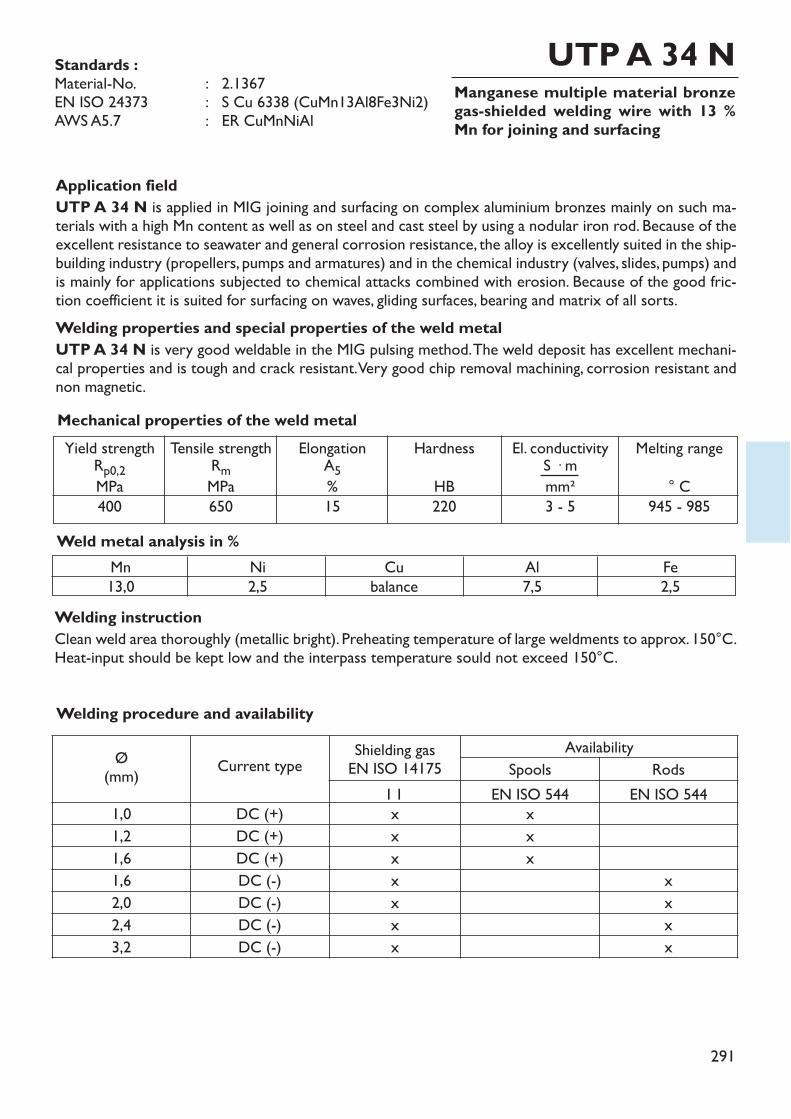
291
Manganese multiple material bronzegas-shielded welding wire with 13 %Mn for joining and surfacing
Welding instructionClean weld area thoroughly (metallic bright). Preheating temperature of large weldments to approx. 150°C.Heat-input should be kept low and the interpass temperature sould not exceed 150°C.
Standards :Material-No. : 2.1367EN ISO 24373 : S Cu 6338 (CuMn13Al8Fe3Ni2)AWS A5.7 : ER CuMnNiAl
Application fieldUTP A 34 N is applied in MIG joining and surfacing on complex aluminium bronzes mainly on such ma-terials with a high Mn content as well as on steel and cast steel by using a nodular iron rod. Because of theexcellent resistance to seawater and general corrosion resistance, the alloy is excellently suited in the ship-building industry (propellers, pumps and armatures) and in the chemical industry (valves, slides, pumps) andis mainly for applications subjected to chemical attacks combined with erosion. Because of the good fric-tion coefficient it is suited for surfacing on waves, gliding surfaces, bearing and matrix of all sorts.Welding properties and special properties of the weld metalUTP A 34 N is very good weldable in the MIG pulsing method. The weld deposit has excellent mechani-cal properties and is tough and crack resistant. Very good chip removal machining, corrosion resistant andnon magnetic.
UTP A 34 N
Weld metal analysis in %Mn13,0
Ni2,5
Al7,5
Fe2,5
Mechanical properties of the weld metalYield strengthRp0,2MPa
400
Tensile strengthRmMPa650
ElongationA5%15
HardnessHB220
El. conductivityS � mmm²3 - 5
Melting range° C
945 - 985
Welding procedure and availability
Ø(mm) Current type Shielding gas
EN ISO 14175Availability
Spools RodsI 1 EN ISO 544 EN ISO 544
1,0 DC (+) x x1,2 DC (+) x x1,6 DC (+) x x1,6 DC (-) x x2,0 DC (-) x x2,4 DC (-) x x3,2 DC (-) x x
Cubalance
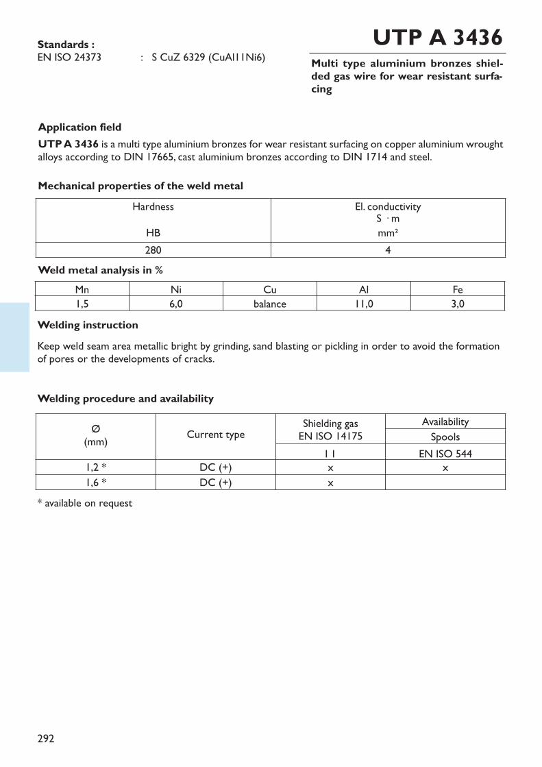
292
Multi type aluminium bronzes shiel-ded gas wire for wear resistant surfa-cing
Application fieldUTP A 3436 is a multi type aluminium bronzes for wear resistant surfacing on copper aluminium wroughtalloys according to DIN 17665, cast aluminium bronzes according to DIN 1714 and steel.
Welding instructionKeep weld seam area metallic bright by grinding, sand blasting or pickling in order to avoid the formationof pores or the developments of cracks.
Weld metal analysis in %
Standards :EN ISO 24373 : S CuZ 6329 (CuAl11Ni6)
UTP A 3436
Mechanical properties of the weld metal
Mn Ni Cu Al Fe1,5 6,0 balance 11,0 3,0
HardnessHB
El. conductivityS � mmm²
280 4
* available on request
Welding procedure and availability
Ø(mm) Current type Shielding gas
EN ISO 14175AvailabilitySpools
I 1 EN ISO 5441,2 * DC (+) x x1,6 * DC (+) x
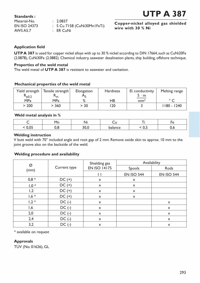
293
Copper-nickel alloyed gas shieldedwire with 30 % Ni
Application fieldUTP A 387 is used for copper nickel alloys with up to 30 % nickel according to DIN 17664, such as CuNi20Fe(2.0878), CuNi30Fe (2.0882). Chemical industry, seawater desalination plants, ship building, offshore technique. Properties of the weld metalThe weld metal of UTP A 387 is resistant to seawater and cavitation.
Welding instructionV butt weld with 70° included angle and root gap of 2 mm. Remove oxide skin to approx. 10 mm to thejoint groove also on the backside of the weld.
Weld metal analysis in %
Standards :Material-No. : 2.0837EN ISO 24373 : S Cu 7158 (CuNi30Mn1FeTi)AWS A5.7 : ER CuNi
UTP A 387
Mechanical properties of the weld metalYield strengthRp0,2MPa
> 200
Tensile strengthRmMPa> 360
ElongationA5%> 30
HardnessHB120
El. conductivityS � mmm²3
Melting range° C
1180 - 1240
C Mn Ni Cu Ti Fe< 0,05 0,8 30,0 balance < 0,5 0,6
ApprovalsTÜV (No. 01626), GL
* available on request
Welding procedure and availability
Ø(mm) Current type Shielding gas
EN ISO 14175Availability
Spools RodsI 1 EN ISO 544 EN ISO 544
0,8 * DC (+) x x1,0 * DC (+) x x1,2 DC (+) x x1,6 * DC (+) x x1,2 * DC (-) x x1,6 DC (-) x x2,0 DC (-) x x2,4 DC (-) x x3,2 DC (-) x x
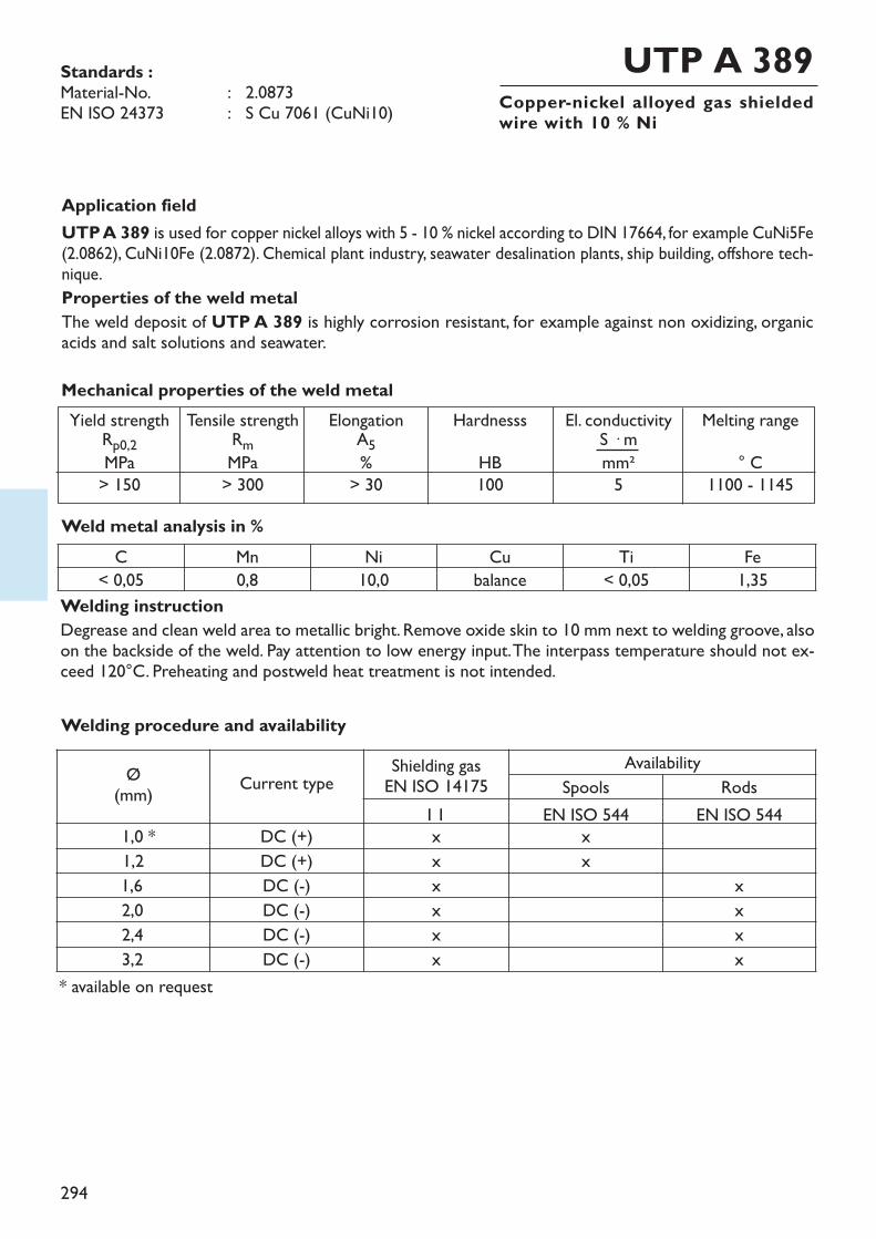
294
Copper-nickel alloyed gas shieldedwire with 10 % Ni
Application fieldUTP A 389 is used for copper nickel alloys with 5 - 10 % nickel according to DIN 17664, for example CuNi5Fe(2.0862), CuNi10Fe (2.0872). Chemical plant industry, seawater desalination plants, ship building, offshore tech-nique.Properties of the weld metalThe weld deposit of UTP A 389 is highly corrosion resistant, for example against non oxidizing, organicacids and salt solutions and seawater.
Welding instructionDegrease and clean weld area to metallic bright. Remove oxide skin to 10 mm next to welding groove, alsoon the backside of the weld. Pay attention to low energy input. The interpass temperature should not ex-ceed 120°C. Preheating and postweld heat treatment is not intended.
Weld metal analysis in %
Standards :Material-No. : 2.0873EN ISO 24373 : S Cu 7061 (CuNi10)
UTP A 389
Mechanical properties of the weld metalYield strengthRp0,2MPa
> 150
Tensile strengthRmMPa> 300
ElongationA5%> 30
HardnesssHB100
El. conductivityS � mmm²5
Melting range° C
1100 - 1145
C Mn Ni Cu Ti Fe< 0,05 0,8 10,0 balance < 0,05 1,35
Welding procedure and availability
Ø(mm) Current type Shielding gas
EN ISO 14175Availability
Spools RodsI 1 EN ISO 544 EN ISO 544
1,0 * DC (+) x x1,2 DC (+) x x1,6 DC (-) x x2,0 DC (-) x x2,4 DC (-) x x3,2 DC (-) x x
* available on request
295

296
Index
Stainless and acid resistant welding consumablesHeat resistant welding consumables
stick electrodessolid rods and wiresflux cored wireswires and fluxes for submerged arc welding
Group 6Welding consumablesfor welding stainless,acis- and heat resi-stant steels
297
Stainless and acid resistant welding consumables
Heat resistant welding consumables
stick electrodessolid rods and wiresflux cored wireswires and fluxes for submerged arc welding
312 – 335336 – 349350 – 353354 – 355
page xxx
356 – 358359
stick electrodessolid rods and wires
Group 6Welding consumablesfor welding stainless,acis- and heat resi-stant steels
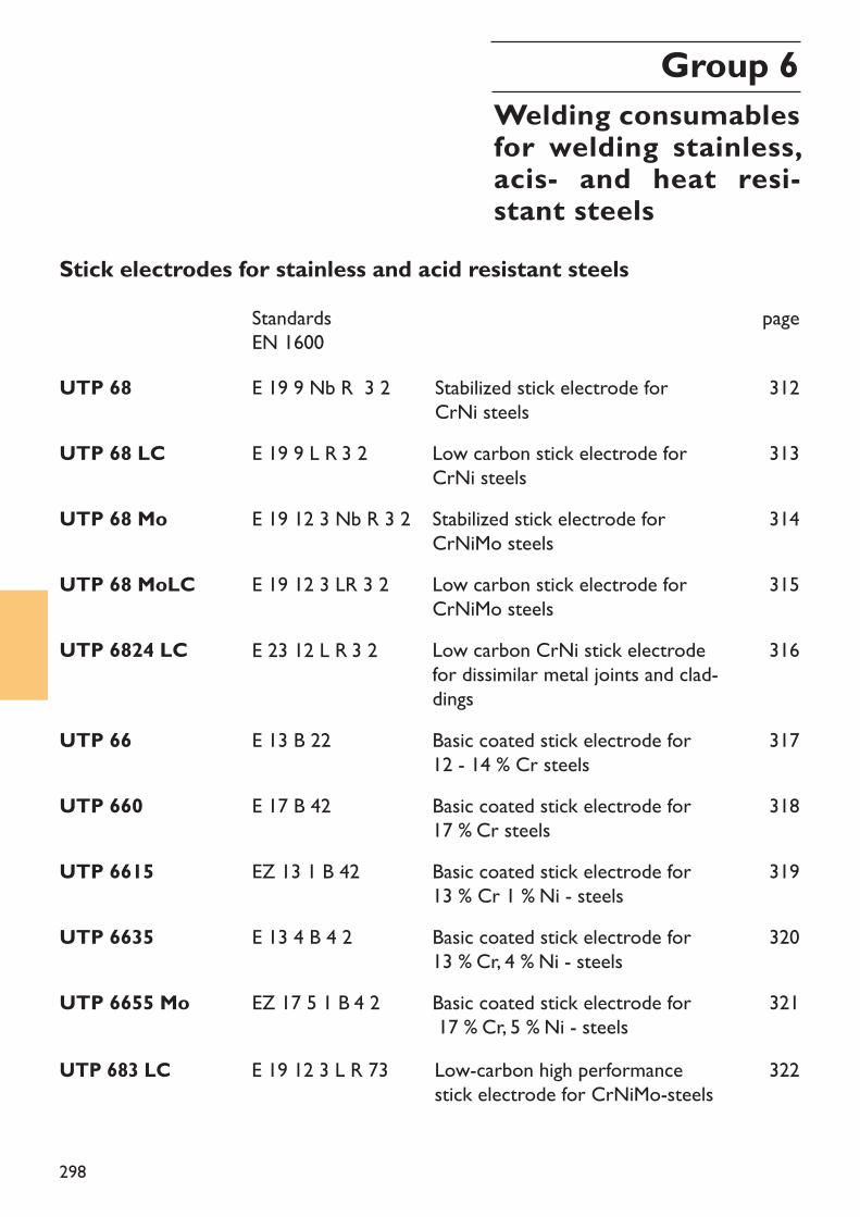
298
Stick electrodes for stainless and acid resistant steelsStandardsEN 1600
page
UTP 68 E 19 9 Nb R 3 2 Stabilized stick electrode for CrNi steels
312
UTP 68 LC E 19 9 L R 3 2 Low carbon stick electrode for CrNi steels
313
UTP 68 Mo E 19 12 3 Nb R 3 2 Stabilized stick electrode for CrNiMo steels
314
UTP 68 MoLC E 19 12 3 LR 3 2 Low carbon stick electrode forCrNiMo steels
315
UTP 6824 LC Low carbon CrNi stick electrodefor dissimilar metal joints and clad-dings
316
UTP 66 E 13 B 22 Basic coated stick electrode for 12 - 14 % Cr steels
317
UTP 660 E 17 B 42 Basic coated stick electrode for 17 % Cr steels
318
319UTP 6615 EZ 13 1 B 42 Basic coated stick electrode for13 % Cr 1 % Ni - steels
UTP 6635 E 13 4 B 4 2 Basic coated stick electrode for13 % Cr, 4 % Ni - steels
320
UTP 6655 Mo EZ 17 5 1 B 4 2 Basic coated stick electrode for17 % Cr, 5 % Ni - steels
321
E 23 12 L R 3 2
Group 6Welding consumablesfor welding stainless,acis- and heat resi-stant steels
UTP 683 LC E 19 12 3 L R 73 Low-carbon high performancestick electrode for CrNiMo-steels
322
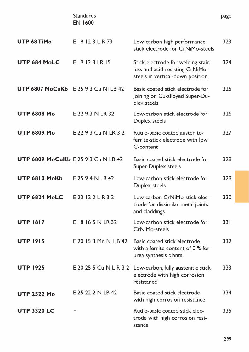
299
StandardsEN 1600
page
UTP 684 MoLC E 19 12 3 LR 15 Stick electrode for welding stain-less and acid-resisting CrNiMo-steels in vertical-down position
324
UTP 6807 MoCuKb E 25 9 3 Cu Ni LB 42 Basic coated stick electrode forjoining on Cu-alloyed Super-Du-plex steels
325
UTP 68 TiMo E 19 12 3 L R 73 Low-carbon high performancestick electrode for CrNiMo-steels
323
UTP 6808 Mo E 22 9 3 N LR 32 Low-carbon stick electrode forDuplex steels
326
UTP 6809 Mo E 22 9 3 Cu N LR 3 2 Rutile-basic coated austenite-ferrite-stick electrode with lowC-content
327
UTP 6809 MoCuKb E 25 9 3 Cu N LB 42 Basic coated stick electrode forSuper-Duplex steels
328
UTP 6810 MoKb E 25 9 4 N LB 42 Low-carbon stick electrode forDuplex steels
329
UTP 6824 MoLC E 23 12 2 L R 3 2 Low carbon CrNiMo-stick elec-trode for dissimilar metal jointsand claddings
330
UTP 1817 E 18 16 5 N LR 32 Low-carbon stick electrode forCrNiMo-steels
331
UTP 1915 E 20 15 3 Mn N L B 42 Basic coated stick electrodewith a ferrite content of 0 % forurea synthesis plants
332
UTP 1925 E 20 25 5 Cu N L R 3 2 Low-carbon, fully austenitic stickelectrode with high corrosionresistance
333
UTP 2522 Mo E 25 22 2 N LB 42 Basic coated stick electrodewith high corrosion resistanceRutile-basic coated stick elec-trode with high corrosion resi-stance
334
UTP 3320 LC – 335
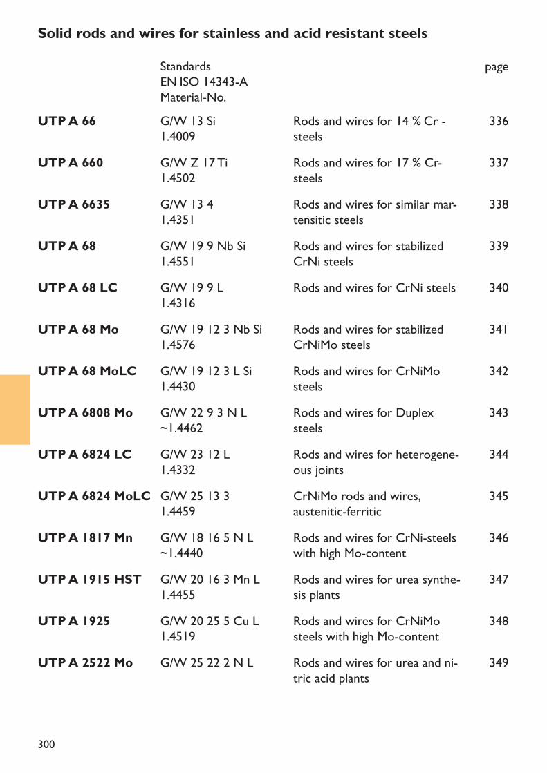
300
UTP A 660 G/W Z 17 Ti1.4502
Rods and wires for 17 % Cr-steels
337
UTP A 6635 G/W 13 4 1.4351
Rods and wires for similar mar-tensitic steels
338
UTP A 68 G/W 19 9 Nb Si1.4551
Rods and wires for stabilizedCrNi steels
339
UTP A 68 LC G/W 19 9 L 1.4316
Rods and wires for CrNi steels 340
UTP A 68 Mo G/W 19 12 3 Nb Si1.4576
Rods and wires for stabilizedCrNiMo steels
341
UTP A 68 MoLC G/W 19 12 3 L Si1.4430
Rods and wires for CrNiMosteels
342
UTP A 6808 Mo G/W 22 9 3 N L~1.4462
Rods and wires for Duplexsteels
343
UTP A 6824 LC G/W 23 12 L1.4332
Rods and wires for heterogene-ous joints
344
UTP A 6824 MoLC G/W 25 13 31.4459
CrNiMo rods and wires,austenitic-ferritic
345
UTP A 1817 Mn G/W 18 16 5 N L~1.4440
Rods and wires for CrNi-steelswith high Mo-content
346
UTP A 1915 HST G/W 20 16 3 Mn L1.4455
Rods and wires for urea synthe-sis plants
347
UTP A 1925 G/W 20 25 5 Cu L1.4519
Rods and wires for CrNiMosteels with high Mo-content
348
UTP A 2522 Mo G/W 25 22 2 N L Rods and wires for urea and ni-tric acid plants
349
Solid rods and wires for stainless and acid resistant steelsStandardsEN ISO 14343-AMaterial-No.
page
UTP A 66 G/W 13 Si1.4009
Rods and wires for 14 % Cr -steels
336
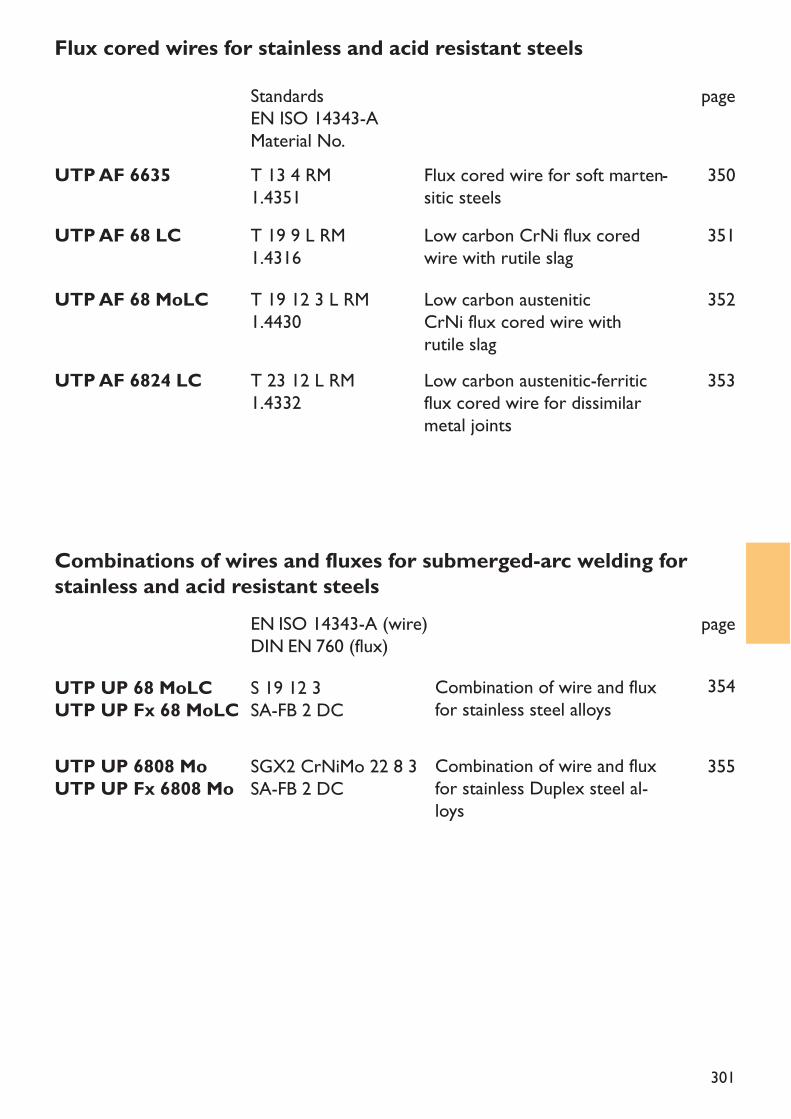
301
UTP AF 68 LC T 19 9 L RM1.4316
Low carbon CrNi flux coredwire with rutile slag
351
UTP AF 68 MoLC T 19 12 3 L RM1.4430
Low carbon austenitic CrNi flux cored wire with rutile slag
352
UTP AF 6824 LC T 23 12 L RM1.4332
Low carbon austenitic-ferritic flux cored wire for dissimilarmetal joints
Combination of wire and fluxfor stainless steel alloys
Combination of wire and fluxfor stainless Duplex steel al-loys
353
Flux cored wires for stainless and acid resistant steelsStandardsEN ISO 14343-AMaterial No.
page
UTP AF 6635 T 13 4 RM1.4351
Flux cored wire for soft marten-sitic steels
350
UTP UP 6808 MoUTP UP Fx 6808 Mo
SGX2 CrNiMo 22 8 3SA-FB 2 DC
355
Combinations of wires and fluxes for submerged-arc welding forstainless and acid resistant steels
EN ISO 14343-A (wire)DIN EN 760 (flux)
page
UTP UP 68 MoLCUTP UP Fx 68 MoLC
S 19 12 3SA-FB 2 DC
354
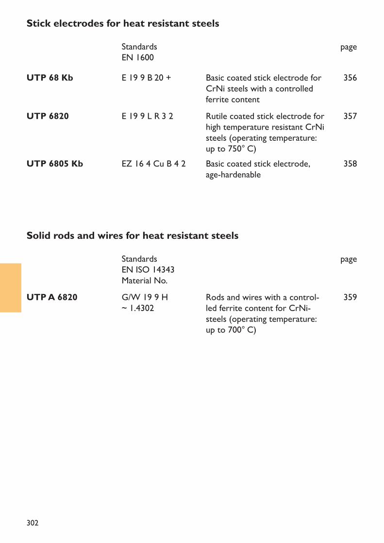
302
Stick electrodes for heat resistant steelsStandardsEN 1600
page
UTP 68 Kb E 19 9 B 20 + Basic coated stick electrode forCrNi steels with a controlledferrite content
356
UTP 6820 E 19 9 L R 3 2 Rutile coated stick electrode forhigh temperature resistant CrNisteels (operating temperature:up to 750° C)
357
UTP 6805 Kb EZ 16 4 Cu B 4 2 Basic coated stick electrode, age-hardenable
358
Solid rods and wires for heat resistant steelsStandardsEN ISO 14343Material No.
page
UTP A 6820 G/W 19 9 H~ 1.4302
Rods and wires with a control-led ferrite content for CrNi-steels (operating temperature:up to 700° C)
359
303
Welding consumablesHigh alloyed stainless and heat resistant steels are selected to correspond to the requirementsof the workpiece.The decision of which kind of base material is being used is depending on the working proper-ties, to which also the weldability is accounted, the corrosion resistance to the medias involved,the working temperature and, on oven constructions, the oven atmosphere. The selection of thewelding consumable is as important as the selection of the base material.The welding consumables are in general of an analysis identical to the base metal.WeldabilityMartensitic and ferritic chromium steelsMartensitic and ferritic chromium steels shall only be welded with identical consumables if co-lour match or identical mechanical properties is required. Otherwise the welding should bedone with austenitic-ferritic or fully austenitic consumables. The welding has to be done with apre-heating and an interpass temperature of 200 – 300° C. This temperature range has to bemaintained during the whole welding process. Immediately after welding, a post weld tempering,corresponding to the base metal (700 – 750° C) has to be made. If the welding has been madewith a non identical consumable, there may be a danger of embrittlement (Sigma phase occur-rence).Soft martensitic chrome-nickel steelsSoft martensitic chrome-nickel steels are welded with identical consumables. When weldingheavy sections, a pre-heating of approx. 100° C is necessary. To improve the toughness, the wel-ding joint should be subjected to a tempering process.Austenitic chrome-nickel-molybdenum steelsTo weld austenitic CrNi- or CrNiMo steels corresponding consumables are being used. To im-prove the safety against hot cracks, the welding consumable should have a delta ferrite contentof 5 – 15 %.To weld high corrosion resistant, fully austenitic steels, the welding consumable has to be ofidentical quality.The interpass temperature has to be limited to 175° C respectively 150° C. A pre-heating is onlynecessary on parts with heavy sections (100 – 150° C). The welding has to be done with a li-mited heat input (max. 15 KJ/cm). Also the welding speed is important, the ratio bead width tobead depth should be approx. 1,5 – 2,1.
The welding of stainless and heat resistant steels
304
Welding instructionTotal cleanliness of the joint and its surroundings is of vital importance. Dirt, scale residues,grease and oil should be removed by mechanical or chemical means. Thermally cut bead flankshave to be grinded with inorganic bound grinding discs.Mechanical cleaning of the welding area has to be done with brushes made of stainless steel.Austenitic steels, having a very high heat expansion coefficient, must be tac-welded in very shortintervals. It is important that the arc is started within the welding area to avoid reduction of thecorrosion resistance of the base metal. The welding must be made with a short arc to limit theheat input. Weaving should be limited to 2 – 3 times the diameter of the electrode core wire.
DryingPrior to the use of the electrodes, they should be stored in the original packets in a dry room.Re-drying is being made at 250 – 300° C during about 2 hours. The re-drying time should notexceed 10 hours. After re-drying and cooling, the electrodes which are not being used imme-diately should be stored in a warm box at 150 – 200° C.
Treatment of welding beadsStainless steels and stainless welding deposits will only be stainless again when the oxide skin andthe colouring, resulting from welding, are being removed. This can be made by mechanical meansor by pickling.
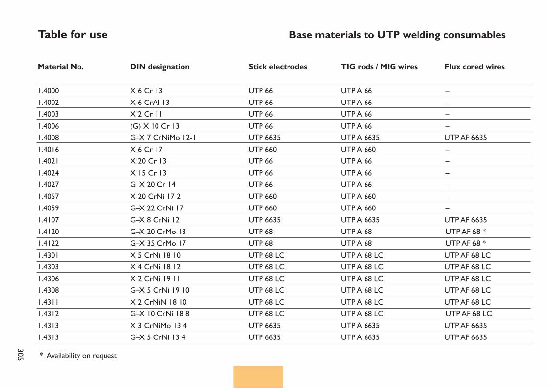
305
Table for use Base materials to UTP welding consumables
Material No.
1.40001.40021.40031.40061.40081.40161.40211.40241.40271.40571.40591.41071.41201.41221.43011.43031.43061.43081.43111.43121.43131.4313
X 6 Cr 13X 6 CrAl 13X 2 Cr 11(G) X 10 Cr 13G–X 7 CrNiMo 12-1X 6 Cr 17X 20 Cr 13X 15 Cr 13G–X 20 Cr 14X 20 CrNi 17 2G–X 22 CrNi 17G–X 8 CrNi 12G–X 20 CrMo 13G–X 35 CrMo 17X 5 CrNi 18 10X 4 CrNi 18 12X 2 CrNi 19 11G–X 5 CrNi 19 10X 2 CrNiN 18 10G–X 10 CrNi 18 8X 3 CrNiMo 13 4G–X 5 CrNi 13 4
UTP 66UTP 66UTP 66UTP 66UTP 6635UTP 660UTP 66UTP 66UTP 66UTP 660UTP 660UTP 6635UTP 68UTP 68UTP 68 LCUTP 68 LCUTP 68 LCUTP 68 LCUTP 68 LCUTP 68 LCUTP 6635UTP 6635
UTP A 66UTP A 66 UTP A 66 UTP A 66 UTP A 6635 UTP A 660UTP A 66UTP A 66UTP A 66UTP A 660 UTP A 660 UTP A 6635 UTP A 68UTP A 68UTP A 68 LC UTP A 68 LC UTP A 68 LC UTP A 68 LC UTP A 68 LC UTP A 68 LC UTP A 6635 UTP A 6635
––––UTP AF 6635––––––UTP AF 6635UTP AF 68 *UTP AF 68 *UTP AF 68 LC UTP AF 68 LC UTP AF 68 LC UTP AF 68 LC UTP AF 68 LCUTP AF 68 LCUTP AF 6635UTP AF 6635
Stick electrodesDIN designation TIG rods / MIG wires Flux cored wires
* Availability on request
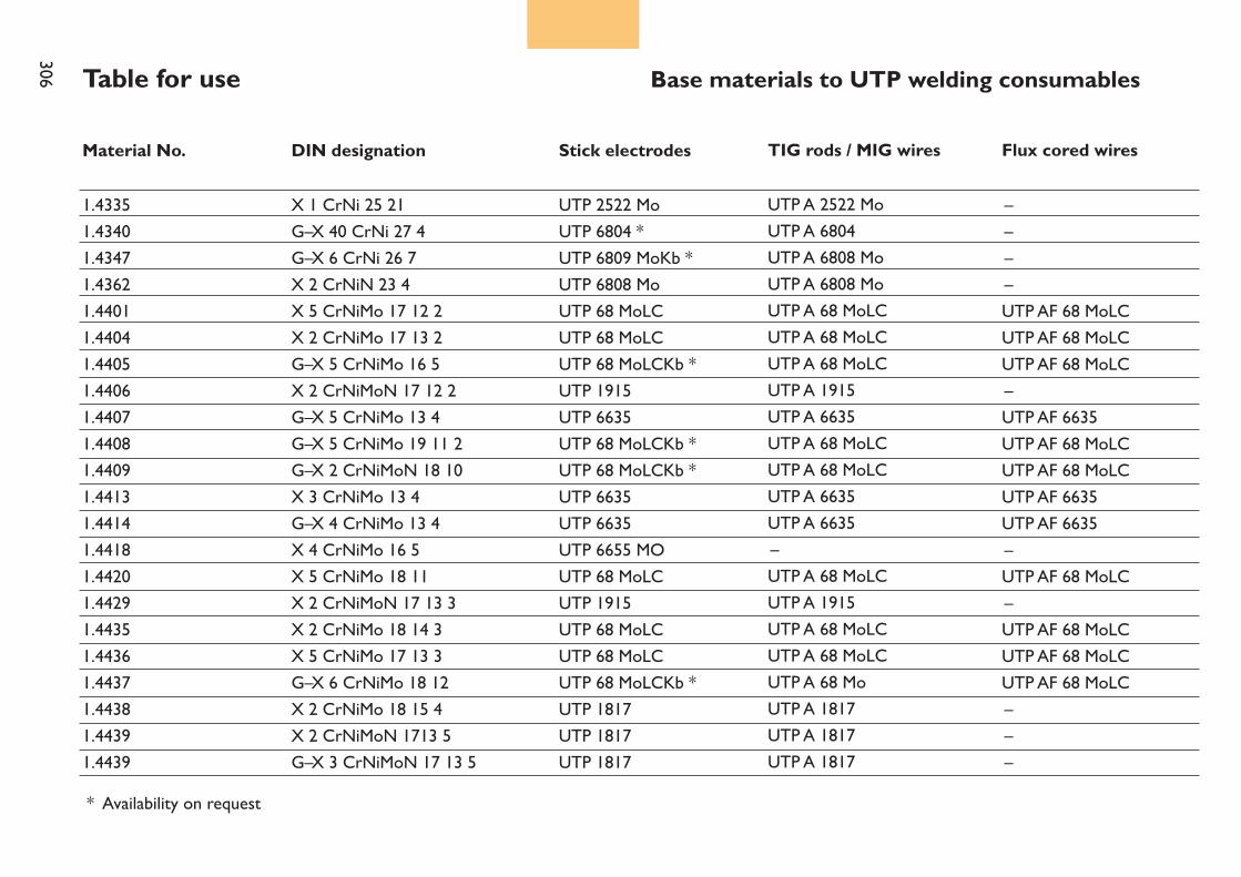
306 Table for use Base materials to UTP welding consumables
Material No.
1.43351.43401.43471.43621.44011.44041.44051.44061.44071.44081.44091.44131.44141.44181.44201.44291.44351.44361.44371.44381.44391.4439
X 1 CrNi 25 21G–X 40 CrNi 27 4G–X 6 CrNi 26 7X 2 CrNiN 23 4X 5 CrNiMo 17 12 2X 2 CrNiMo 17 13 2G–X 5 CrNiMo 16 5X 2 CrNiMoN 17 12 2G–X 5 CrNiMo 13 4G–X 5 CrNiMo 19 11 2G–X 2 CrNiMoN 18 10X 3 CrNiMo 13 4G–X 4 CrNiMo 13 4X 4 CrNiMo 16 5X 5 CrNiMo 18 11X 2 CrNiMoN 17 13 3X 2 CrNiMo 18 14 3X 5 CrNiMo 17 13 3G–X 6 CrNiMo 18 12X 2 CrNiMo 18 15 4X 2 CrNiMoN 1713 5G–X 3 CrNiMoN 17 13 5
UTP 2522 MoUTP 6804 *UTP 6809 MoKb *UTP 6808 MoUTP 68 MoLCUTP 68 MoLCUTP 68 MoLCKb *UTP 1915UTP 6635UTP 68 MoLCKb *UTP 68 MoLCKb *UTP 6635UTP 6635UTP 6655 MOUTP 68 MoLCUTP 1915UTP 68 MoLCUTP 68 MoLCUTP 68 MoLCKb *UTP 1817UTP 1817UTP 1817
UTP A 2522 Mo UTP A 6804UTP A 6808 Mo UTP A 6808 Mo UTP A 68 MoLC UTP A 68 MoLC UTP A 68 MoLC UTP A 1915 UTP A 6635UTP A 68 MoLCUTP A 68 MoLCUTP A 6635UTP A 6635–UTP A 68 MoLCUTP A 1915 UTP A 68 MoLC UTP A 68 MoLC UTP A 68 MoUTP A 1817UTP A 1817UTP A 1817
––––UTP AF 68 MoLCUTP AF 68 MoLCUTP AF 68 MoLC–UTP AF 6635UTP AF 68 MoLCUTP AF 68 MoLCUTP AF 6635 UTP AF 6635–UTP AF 68 MoLC–UTP AF 68 MoLCUTP AF 68 MoLCUTP AF 68 MoLC–––
Stick electrodes DIN designation TIG rods / MIG wires Flux cored wires
* Availability on request
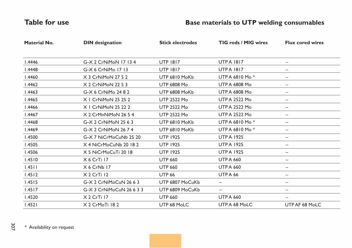
307
Table for use Base materials to UTP welding consumables
Material No. Stick electrodes DIN designation TIG rods / MIG wires Flux cored wires
1.44461.44481.44601.44621.44631.44651.44661.44671.44681.44691.45001.45051.45061.45101.45111.45121.45151.45171.45201.4521
G–X 2 CrNiMoN 17 13 4G–X 6 CrNiMo 17 13X 3 CrNiMoN 27 5 2X 2 CrNiMoN 22 5 3G–X 6 CrNiMo 24 8 2X 1 CrNiMoN 25 25 2X 1 CrNiMoN 25 22 2X 2 CrMnNiMoN 26 5 4G–X 2 CrNiMoN 25 6 3G–X 2 CrNiMoN 26 7 4G–X 7 NiCrMoCuNb 25 20X 4 NiCrMoCuNb 20 18 2X 5 NiCrMoCuTi 20 18X 6 CrTi 17X 6 CrNb 17X 2 CrTi 12G–X 2 CrNiMoCuN 26 6 3G–X 3 CrNiMoCuN 26 6 3 3X 2 CrTi 17X 2 CrMoTi 18 2
UTP 1817UTP 1817UTP 6810 MoKbUTP 6808 MoUTP 6808 MoKbUTP 2522 MoUTP 2522 MoUTP 2522 MoUTP 6810 MoKbUTP 6810 MoKbUTP 1925UTP 1925UTP 1925UTP 660UTP 660UTP 66UTP 6807 MoCuKbUTP 6809 MoCuKbUTP 660UTP 68 MoLC
UTP A 1817 UTP A 1817 UTP A 6810 Mo *UTP A 6808 Mo UTP A 6808 Mo UTP A 2522 Mo UTP A 2522 Mo UTP A 2522 Mo UTP A 6810 Mo *UTP A 6810 Mo * UTP A 1925 UTP A 1925 UTP A 1925 UTP A 660 UTP A 660 UTP A 66––UTP A 660UTP A 68 MoLC
–––––––––––––––––––UTP AF 68 MoLC
* Availability on request
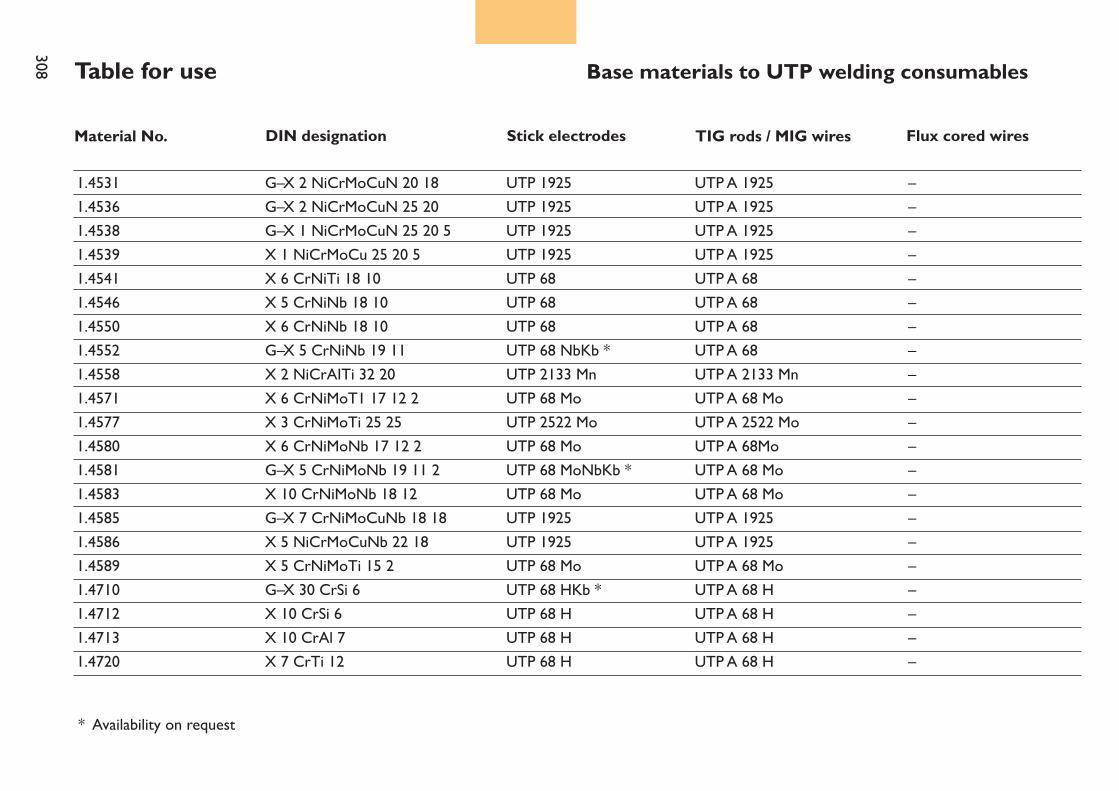
308 Table for use Base materials to UTP welding consumables
Material No. Stick electrodes DIN designation TIG rods / MIG wires Flux cored wires
1.45311.45361.45381.45391.45411.45461.45501.45521.45581.45711.45771.45801.45811.45831.45851.45861.45891.47101.47121.47131.4720
G–X 2 NiCrMoCuN 20 18G–X 2 NiCrMoCuN 25 20G–X 1 NiCrMoCuN 25 20 5X 1 NiCrMoCu 25 20 5X 6 CrNiTi 18 10X 5 CrNiNb 18 10X 6 CrNiNb 18 10G–X 5 CrNiNb 19 11X 2 NiCrAITi 32 20X 6 CrNiMoT1 17 12 2X 3 CrNiMoTi 25 25X 6 CrNiMoNb 17 12 2G–X 5 CrNiMoNb 19 11 2X 10 CrNiMoNb 18 12G–X 7 CrNiMoCuNb 18 18X 5 NiCrMoCuNb 22 18X 5 CrNiMoTi 15 2G–X 30 CrSi 6X 10 CrSi 6X 10 CrAl 7X 7 CrTi 12
UTP 1925UTP 1925UTP 1925UTP 1925UTP 68UTP 68UTP 68UTP 68 NbKb *UTP 2133 MnUTP 68 MoUTP 2522 MoUTP 68 MoUTP 68 MoNbKb *UTP 68 MoUTP 1925UTP 1925UTP 68 MoUTP 68 HKb *UTP 68 HUTP 68 HUTP 68 H
UTP A 1925UTP A 1925UTP A 1925UTP A 1925UTP A 68UTP A 68UTP A 68UTP A 68UTP A 2133 MnUTP A 68 MoUTP A 2522 MoUTP A 68MoUTP A 68 MoUTP A 68 MoUTP A 1925UTP A 1925UTP A 68 MoUTP A 68 HUTP A 68 HUTP A 68 HUTP A 68 H
–––––––––––––––––––––
* Availability on request
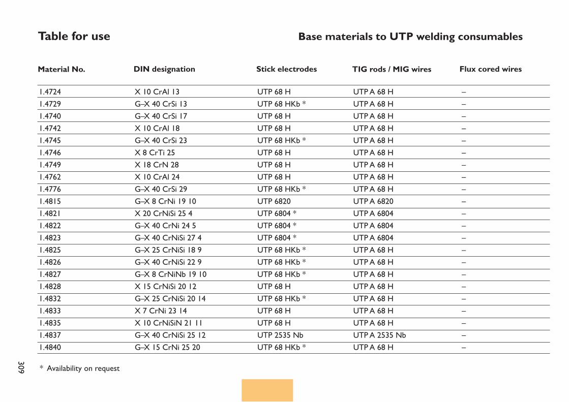
309
Table for use Base materials to UTP welding consumables
Material No. Stick electrodes DIN designation TIG rods / MIG wires Flux cored wires
1.47241.47291.47401.47421.47451.47461.47491.47621.47761.48151.48211.48221.48231.48251.48261.48271.48281.48321.48331.48351.48371.4840
X 10 CrAl 13G–X 40 CrSi 13G–X 40 CrSi 17X 10 CrAl 18G–X 40 CrSi 23X 8 CrTi 25X 18 CrN 28X 10 CrAl 24G–X 40 CrSi 29G–X 8 CrNi 19 10X 20 CrNiSi 25 4G–X 40 CrNi 24 5G–X 40 CrNiSi 27 4G–X 25 CrNiSi 18 9G–X 40 CrNiSi 22 9G–X 8 CrNiNb 19 10X 15 CrNiSi 20 12G–X 25 CrNiSi 20 14X 7 CrNi 23 14X 10 CrNiSiN 21 11G–X 40 CrNiSi 25 12G–X 15 CrNi 25 20
UTP 68 HUTP 68 HKb *UTP 68 HUTP 68 HUTP 68 HKb *UTP 68 HUTP 68 HUTP 68 HUTP 68 HKb *UTP 6820UTP 6804 *UTP 6804 *UTP 6804 *UTP 68 HKb *UTP 68 HKb *UTP 68 HKb *UTP 68 HUTP 68 HKb *UTP 68 HUTP 68 HUTP 2535 NbUTP 68 HKb *
UTP A 68 HUTP A 68 HUTP A 68 HUTP A 68 HUTP A 68 HUTP A 68 HUTP A 68 HUTP A 68 HUTP A 68 HUTP A 6820UTP A 6804UTP A 6804UTP A 6804UTP A 68 HUTP A 68 HUTP A 68 HUTP A 68 HUTP A 68 HUTP A 68 HUTP A 68 HUTP A 2535 NbUTP A 68 H
––––––––––––––––––––––
* Availability on request
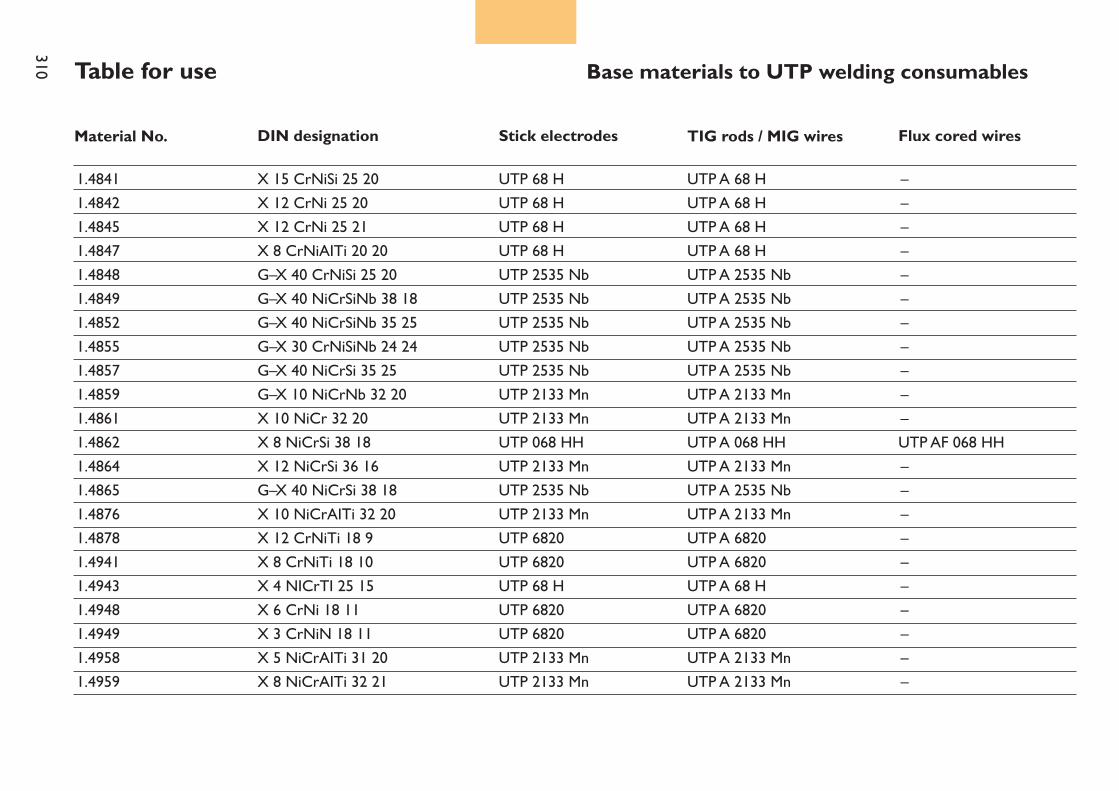
310 Table for use Base materials to UTP welding consumables
Material No. Stick electrodes DIN designation TIG rods / MIG wires Flux cored wires
1.48411.48421.48451.48471.48481.48491.48521.48551.48571.48591.48611.48621.48641.48651.48761.48781.49411.49431.49481.49491.49581.4959
X 15 CrNiSi 25 20X 12 CrNi 25 20X 12 CrNi 25 21X 8 CrNiAITi 20 20G–X 40 CrNiSi 25 20G–X 40 NiCrSiNb 38 18G–X 40 NiCrSiNb 35 25G–X 30 CrNiSiNb 24 24G–X 40 NiCrSi 35 25G–X 10 NiCrNb 32 20X 10 NiCr 32 20X 8 NiCrSi 38 18X 12 NiCrSi 36 16G–X 40 NiCrSi 38 18X 10 NiCrAITi 32 20X 12 CrNiTi 18 9X 8 CrNiTi 18 10X 4 NICrTI 25 15X 6 CrNi 18 11X 3 CrNiN 18 11X 5 NiCrAITi 31 20X 8 NiCrAITi 32 21
UTP 68 HUTP 68 HUTP 68 HUTP 68 HUTP 2535 NbUTP 2535 NbUTP 2535 NbUTP 2535 NbUTP 2535 NbUTP 2133 MnUTP 2133 MnUTP 068 HHUTP 2133 MnUTP 2535 NbUTP 2133 MnUTP 6820UTP 6820UTP 68 HUTP 6820UTP 6820UTP 2133 MnUTP 2133 Mn
UTP A 68 HUTP A 68 HUTP A 68 HUTP A 68 HUTP A 2535 NbUTP A 2535 NbUTP A 2535 NbUTP A 2535 NbUTP A 2535 NbUTP A 2133 MnUTP A 2133 MnUTP A 068 HHUTP A 2133 MnUTP A 2535 NbUTP A 2133 MnUTP A 6820UTP A 6820UTP A 68 HUTP A 6820UTP A 6820UTP A 2133 MnUTP A 2133 Mn
–––––––––––UTP AF 068 HH ––––––––––
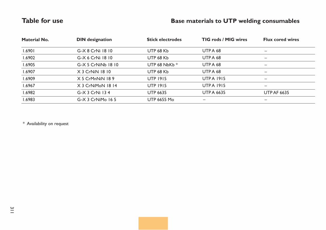
311
Table for use Base materials to UTP welding consumables
Material No. Stick electrodes DIN designation TIG rods / MIG wires Flux cored wires1.69011.69021.69051.69071.69091.69671.69821.6983
G–X 8 CrNi 18 10G–X 6 CrNi 18 10G–X 5 CrNiNb 18 10X 3 CrNiN 18 10X 5 CrMnNiN 18 9X 3 CrNiMoN 18 14G–X 3 CrNi 13 4G–X 3 CrNiMo 16 5
UTP 68 KbUTP 68 KbUTP 68 NbKb *UTP 68 KbUTP 1915 UTP 1915UTP 6635UTP 6655 Mo
UTP A 68UTP A 68UTP A 68UTP A 68UTP A 1915 UTP A 1915UTP A 6635–
––––––UTP AF 6635–
* Availability on request

312
Stabilized stick electrode for CrNi-steels
UTP 68
Welding instructionWeld stick electrode slightly inclined with a short arc. Re-drying 2 hours at 120 – 200° C.
Application fieldThe rutile coated welding stick electrode UTP 68 is suitable for joining and surfacing of stabilized and nonstabilized CrNi steels and CrNi cast steels. The deposit is IC resistant with stabilized base material up to +400°C working temperature. The stick electrode is also applicable for the 2nd layer on cladded CrNi steels.Base materials1.4301, 1.4312, 1.4541,,1.4550, 1.4552Welding characteristics and special properties of the weld metalThe stick electrode is weldable in all positions except vertical down. It has a stable arc and is spatter free.Easy ignition and re-ignition, self detaching slag. Clean and finely wrippled bead without undercutting.
Weld metal analysis in %
Yield strengthRp0,2MPa> 380
Tensile strengthRmMPa> 590
ElongationA%
> 30
Impact strengthKvJoule> 47
Mechanical properties of the weld metal
Current type DC (+) / AC
Standards :Material-No. : 1.4551EN 1600 : E 19 9 Nb R 3 2AWS A5.4 : E 347-17
C0,03
Si0,8
Mn0,5
Cr19,0
Ni10,0
Nb0,25
Febalance
Welding positionsPA PB PC PE PF
Availability / Current adjustmentsStick electrodesAmperage
Ø mm x LA
2,0 x 30040 – 60
2,5 x 35050 – 90
3,2 x 35080 – 110
4,0 x 350110 – 140
ApprovalsTÜV (No. 02592), ABS, GL
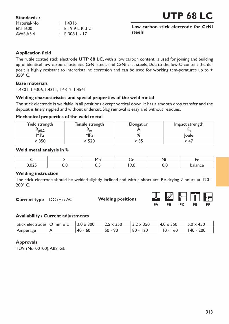
313
Low carbon stick electrode for CrNisteels
UTP 68 LC
Welding instructionThe stick electrode should be welded slightly inclined and with a short arc. Re-drying 2 hours at 120 –200° C.
Application fieldThe rutile coated stick electrode UTP 68 LC, with a low carbon content, is used for joining and buildingup of identical low carbon, austenitic CrNi steels and CrNi cast steels. Due to the low C-content the de-posit is highly resistant to intercristaline corrosion and can be used for working tem-peratures up to +350° C.Base materials1.4301, 1.4306, 1.4311, 1.4312, 1.4541Welding characteristics and special properties of the weld metalThe stick electrode is weldable in all positions except vertical down. It has a smooth drop transfer and thedeposit is finely rippled and without undercut. Slag removal is easy and without residues.
Weld metal analysis in %
Yield strengthRp0,2MPa> 350
Tensile strengthRmMPa> 520
ElongationA%
> 35
Impact strengthKvJoule> 47
Mechanical properties of the weld metal
Current type DC (+) / AC
Standards :Material-No. : 1.4316EN 1600 : E 19 9 L R 3 2AWS A5.4 : E 308 L - 17
C0,025
Si0,8
Mn0,5
Cr19,0
Ni10,0
Febalance
Welding positionsPA PB PC PE PF
ApprovalsTÜV (No. 00100), ABS, GL
Availability / Current adjustmentsStick electrodes Ø mm x L 2,0 x 300 2,5 x 350 3,2 x 350 4,0 x 350 5,0 x 450Amperage A 40 - 60 50 - 90 80 - 120 110 - 160 140 - 200
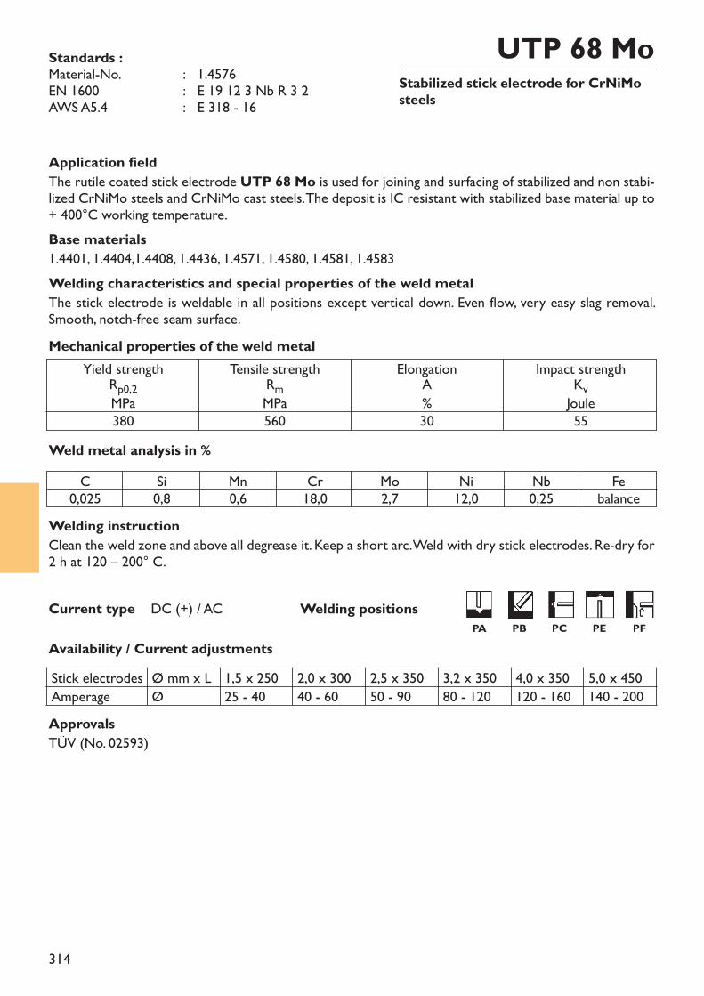
314
Stabilized stick electrode for CrNiMosteels
UTP 68 Mo
Welding instructionClean the weld zone and above all degrease it. Keep a short arc. Weld with dry stick electrodes. Re-dry for2 h at 120 – 200° C.
Application fieldThe rutile coated stick electrode UTP 68 Mo is used for joining and surfacing of stabilized and non stabi-lized CrNiMo steels and CrNiMo cast steels. The deposit is IC resistant with stabilized base material up to+ 400°C working temperature.Base materials1.4401, 1.4404,1.4408, 1.4436, 1.4571, 1.4580, 1.4581, 1.4583Welding characteristics and special properties of the weld metalThe stick electrode is weldable in all positions except vertical down. Even flow, very easy slag removal.Smooth, notch-free seam surface.
Weld metal analysis in %
Yield strengthRp0,2MPa380
Tensile strengthRmMPa560
ElongationA%30
Impact strengthKvJoule55
Mechanical properties of the weld metal
Current type DC (+) / AC
Standards :Material-No. : 1.4576EN 1600 : E 19 12 3 Nb R 3 2AWS A5.4 : E 318 - 16
C0,025
Si0,8
Mn0,6
Cr18,0
Mo2,7
Ni12,0
Nb0,25
Febalance
ApprovalsTÜV (No. 02593)
Availability / Current adjustmentsStick electrodes Ø mm x L 1,5 x 250 2,0 x 300 2,5 x 350 3,2 x 350 4,0 x 350 5,0 x 450Amperage Ø 25 - 40 40 - 60 50 - 90 80 - 120 120 - 160 140 - 200
Welding positionsPA PB PC PE PF
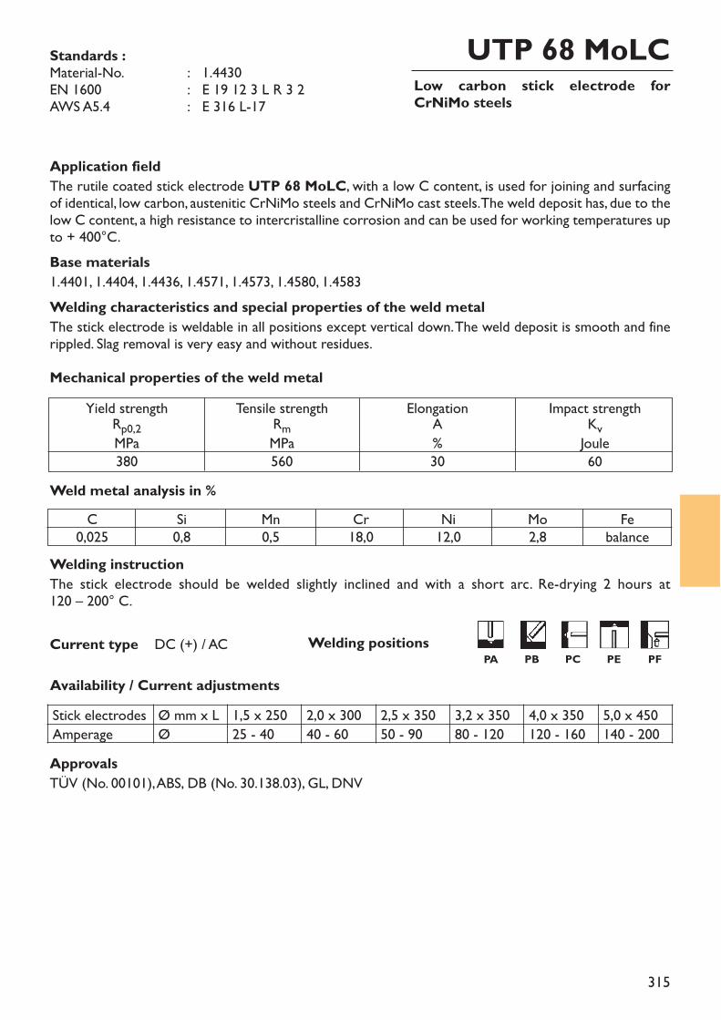
315
Low carbon stick electrode forCrNiMo steels
UTP 68 MoLC
Welding instructionThe stick electrode should be welded slightly inclined and with a short arc. Re-drying 2 hours at 120 – 200° C.
Application fieldThe rutile coated stick electrode UTP 68 MoLC, with a low C content, is used for joining and surfacingof identical, low carbon, austenitic CrNiMo steels and CrNiMo cast steels. The weld deposit has, due to thelow C content, a high resistance to intercristalline corrosion and can be used for working temperatures upto + 400°C.Base materials1.4401, 1.4404, 1.4436, 1.4571, 1.4573, 1.4580, 1.4583Welding characteristics and special properties of the weld metalThe stick electrode is weldable in all positions except vertical down. The weld deposit is smooth and finerippled. Slag removal is very easy and without residues.
Weld metal analysis in %
Yield strengthRp0,2MPa380
Tensile strengthRmMPa560
ElongationA%30
Impact strengthKvJoule60
Mechanical properties of the weld metal
Current type DC (+) / AC
Standards :Material-No. : 1.4430EN 1600 : E 19 12 3 L R 3 2AWS A5.4 : E 316 L-17
C0,025
Si0,8
Mn0,5
Cr18,0
Ni12,0
Mo2,8
Febalance
Welding positionsPA PB PC PE PF
ApprovalsTÜV (No. 00101), ABS, DB (No. 30.138.03), GL, DNV
Availability / Current adjustmentsStick electrodes Ø mm x L 1,5 x 250 2,0 x 300 2,5 x 350 3,2 x 350 4,0 x 350 5,0 x 450Amperage Ø 25 - 40 40 - 60 50 - 90 80 - 120 120 - 160 140 - 200
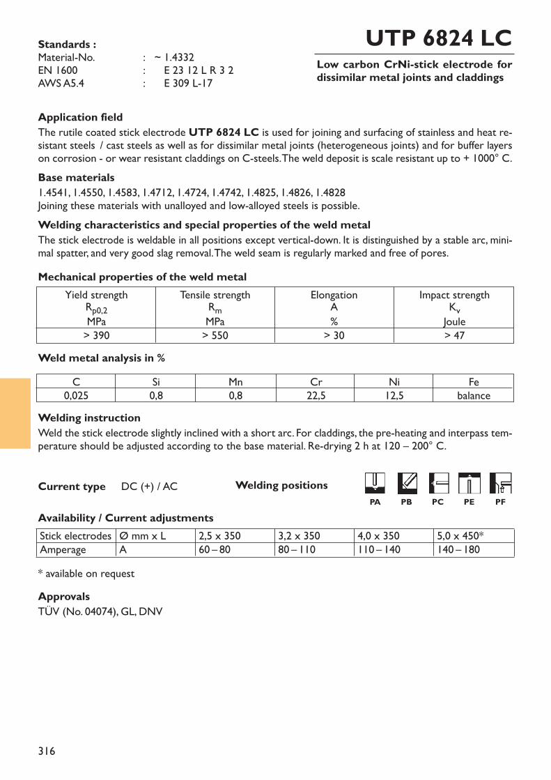
316
Low carbon CrNi-stick electrode fordissimilar metal joints and claddings
UTP 6824 LC
Welding instructionWeld the stick electrode slightly inclined with a short arc. For claddings, the pre-heating and interpass tem-perature should be adjusted according to the base material. Re-drying 2 h at 120 – 200° C.
Application fieldThe rutile coated stick electrode UTP 6824 LC is used for joining and surfacing of stainless and heat re-sistant steels / cast steels as well as for dissimilar metal joints (heterogeneous joints) and for buffer layerson corrosion - or wear resistant claddings on C-steels. The weld deposit is scale resistant up to + 1000° C.Base materials1.4541, 1.4550, 1.4583, 1.4712, 1.4724, 1.4742, 1.4825, 1.4826, 1.4828Joining these materials with unalloyed and low-alloyed steels is possible.Welding characteristics and special properties of the weld metalThe stick electrode is weldable in all positions except vertical-down. It is distinguished by a stable arc, mini-mal spatter, and very good slag removal. The weld seam is regularly marked and free of pores.
Weld metal analysis in %
Yield strengthRp0,2MPa> 390
Tensile strengthRmMPa> 550
ElongationA%
> 30
Impact strengthKvJoule> 47
Mechanical properties of the weld metal
Current type DC (+) / AC
* available on request
Standards :Material-No. : ~ 1.4332EN 1600 : ~ E 23 12 L R 3 2AWS A5.4 : ~ E 309 L-17
C0,025
Si0,8
Mn0,8
Cr22,5
Ni12,5
Febalance
Welding positionsPA PB PC PE PF
Availability / Current adjustmentsStick electrodesAmperage
Ø mm x LA
2,5 x 35060 – 80
3,2 x 35080 – 110
4,0 x 350110 – 140
5,0 x 450*140 – 180
ApprovalsTÜV (No. 04074), GL, DNV
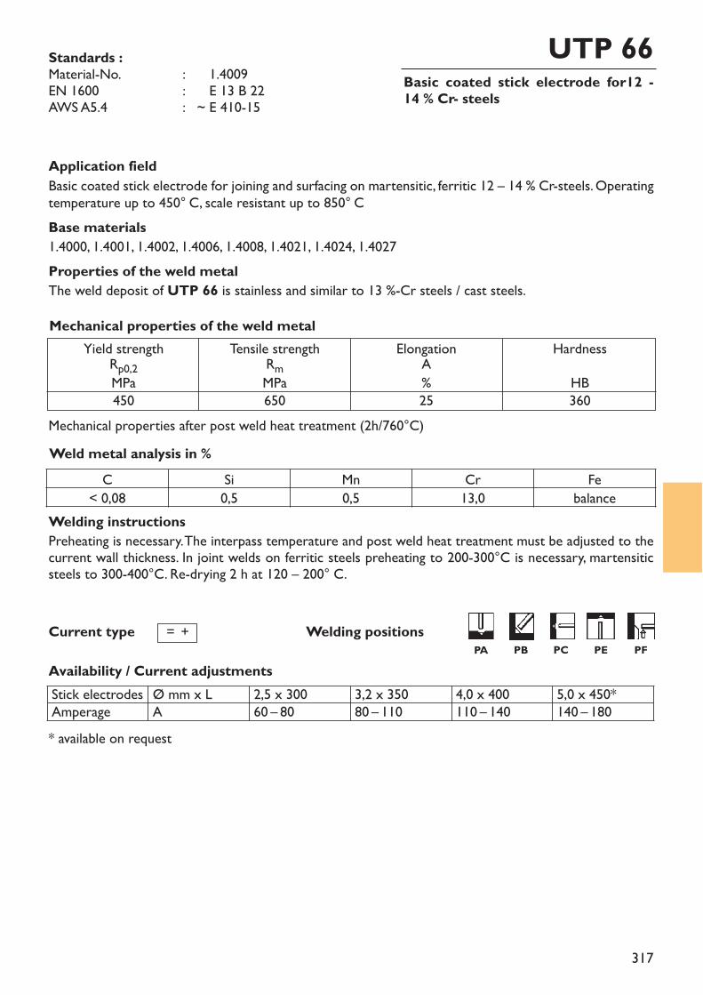
317
Basic coated stick electrode for12 - 14 % Cr- steels
UTP 66
Welding instructionsPreheating is necessary. The interpass temperature and post weld heat treatment must be adjusted to thecurrent wall thickness. In joint welds on ferritic steels preheating to 200-300°C is necessary, martensiticsteels to 300-400°C. Re-drying 2 h at 120 – 200° C.
Standards :Material-No. : ~ 1.4009EN 1600 : ~ E 13 B 22AWS A5.4 : ~ E 410-15
Application fieldBasic coated stick electrode for joining and surfacing on martensitic, ferritic 12 – 14 % Cr-steels. Operatingtemperature up to 450° C, scale resistant up to 850° CBase materials1.4000, 1.4001, 1.4002, 1.4006, 1.4008, 1.4021, 1.4024, 1.4027Properties of the weld metalThe weld deposit of UTP 66 is stainless and similar to 13 %-Cr steels / cast steels.
Weld metal analysis in %
Yield strengthRp0,2MPa450
Tensile strengthRmMPa650
ElongationA%25
Mechanical properties of the weld metal
Welding positionsCurrent type
Availability / Current adjustmentsStick electrodesAmperage
Ø mm x LA
2,5 x 30060 – 80
3,2 x 35080 – 110
4,0 x 400110 – 140
5,0 x 450*140 – 180
* available on request
HardnessHB360
C Si Mn Cr Fe< 0,08 0,5 0,5 13,0 balance
= +PA PB PC PE PF
Mechanical properties after post weld heat treatment (2h/760°C)
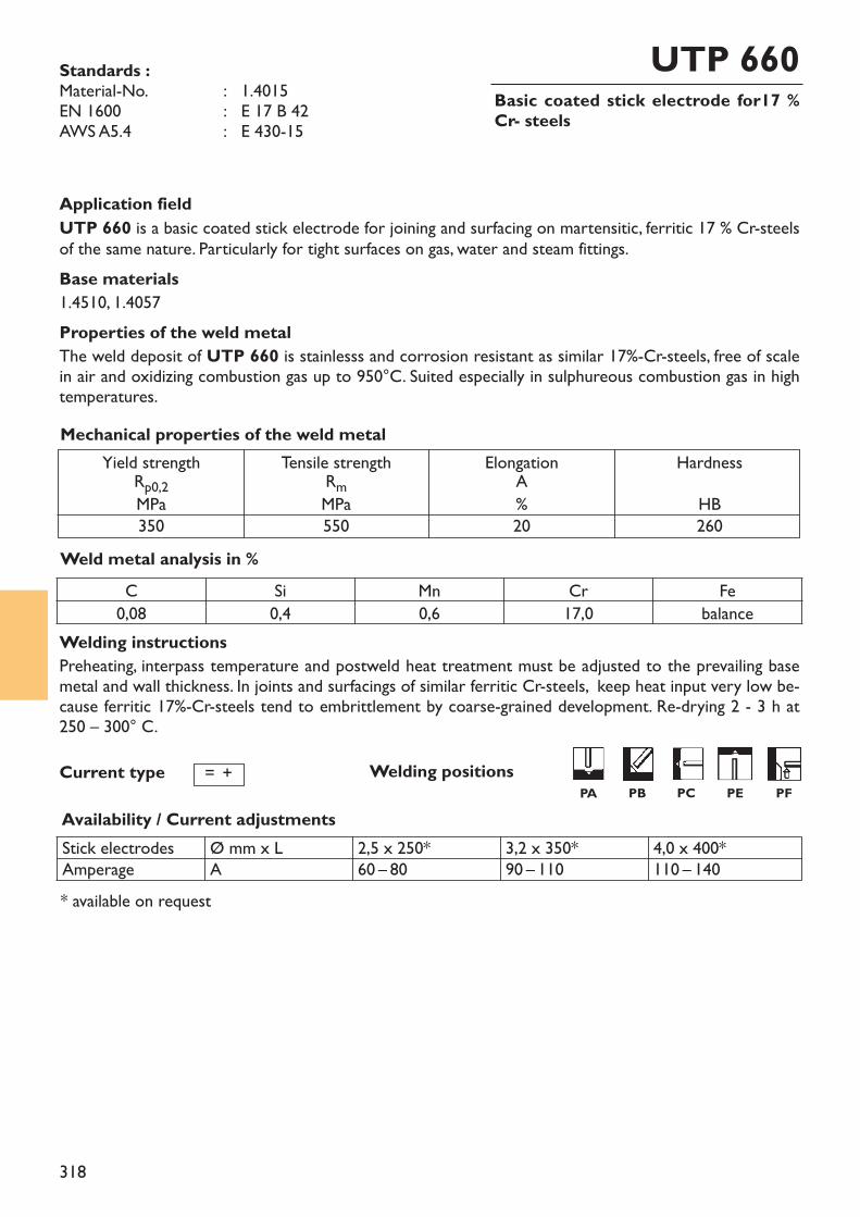
318
Basic coated stick electrode for17 %Cr- steels
UTP 660Standards :Material-No. : 1.4015EN 1600 : E 17 B 42AWS A5.4 : E 430-15
Welding instructionsPreheating, interpass temperature and postweld heat treatment must be adjusted to the prevailing basemetal and wall thickness. In joints and surfacings of similar ferritic Cr-steels, keep heat input very low be-cause ferritic 17%-Cr-steels tend to embrittlement by coarse-grained development. Re-drying 2 - 3 h at 250 – 300° C.
Application fieldUTP 660 is a basic coated stick electrode for joining and surfacing on martensitic, ferritic 17 % Cr-steelsof the same nature. Particularly for tight surfaces on gas, water and steam fittings.Base materials1.4510, 1.4057Properties of the weld metalThe weld deposit of UTP 660 is stainlesss and corrosion resistant as similar 17%-Cr-steels, free of scalein air and oxidizing combustion gas up to 950°C. Suited especially in sulphureous combustion gas in hightemperatures.
Weld metal analysis in %
Yield strengthRp0,2MPa350
Tensile strengthRmMPa550
ElongationA%20
Mechanical properties of the weld metal
Welding positionsCurrent type
Availability / Current adjustmentsStick electrodesAmperage
Ø mm x LA
2,5 x 250*60 – 80
3,2 x 350*90 – 110
4,0 x 400*110 – 140
* available on request
HardnessHB260
C Si Mn Cr Fe0,08 0,4 0,6 17,0 balance
= +PA PB PC PE PF
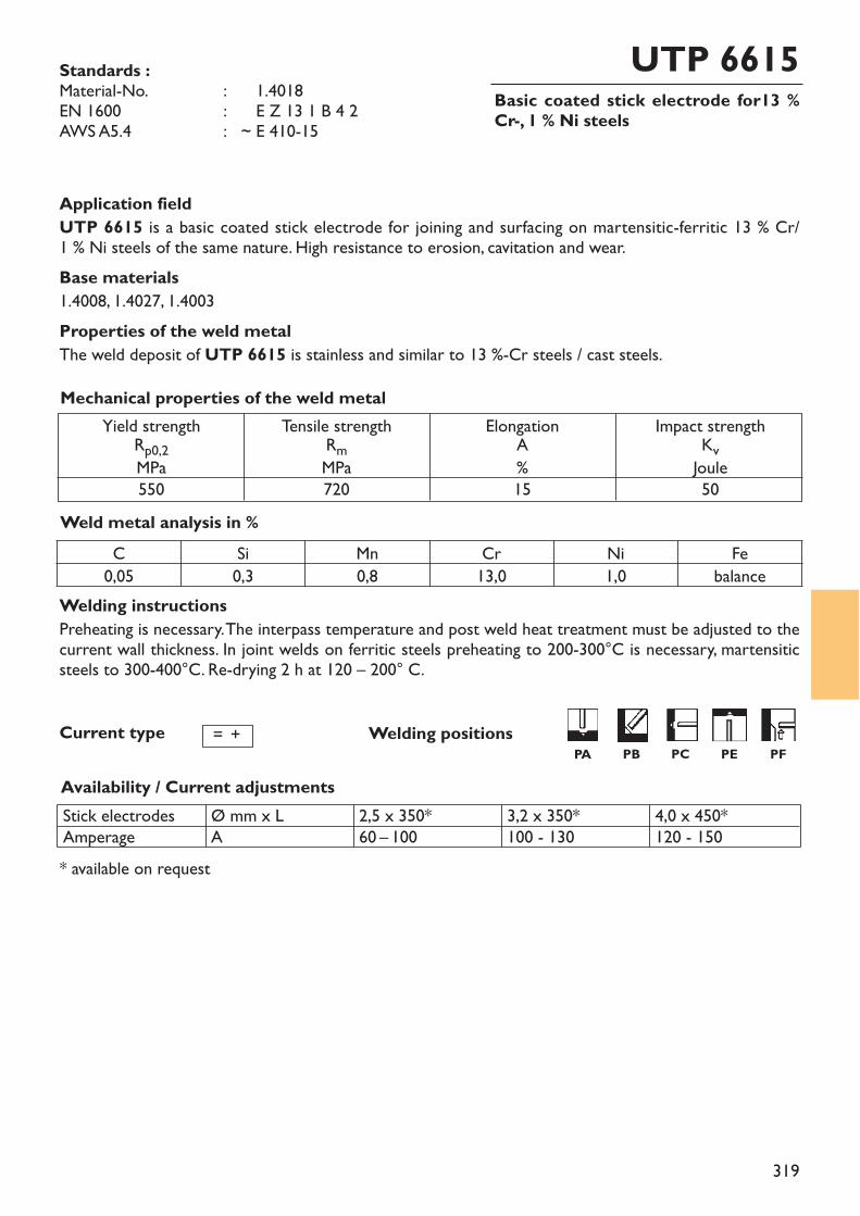
319
Basic coated stick electrode for13 %Cr-, 1 % Ni steels
UTP 6615Standards :Material-No. : ~ 1.4018EN 1600 : ~ E Z 13 1 B 4 2 AWS A5.4 : ~ E 410-15
Welding instructionsPreheating is necessary. The interpass temperature and post weld heat treatment must be adjusted to thecurrent wall thickness. In joint welds on ferritic steels preheating to 200-300°C is necessary, martensiticsteels to 300-400°C. Re-drying 2 h at 120 – 200° C.
Application fieldUTP 6615 is a basic coated stick electrode for joining and surfacing on martensitic-ferritic 13 % Cr/1 % Ni steels of the same nature. High resistance to erosion, cavitation and wear. Base materials1.4008, 1.4027, 1.4003Properties of the weld metalThe weld deposit of UTP 6615 is stainless and similar to 13 %-Cr steels / cast steels.
Weld metal analysis in %
Yield strengthRp0,2MPa550
Tensile strengthRmMPa720
ElongationA%15
Impact strengthKvJoule50
Mechanical properties of the weld metal
Welding positionsCurrent type
Availability / Current adjustmentsStick electrodesAmperage
Ø mm x LA
2,5 x 350*60 – 100
3,2 x 350*100 - 130
4,0 x 450*120 - 150
* available on request
= +
C Si Mn Cr Ni Fe0,05 0,3 0,8 13,0 1,0 balance
PA PB PC PE PF
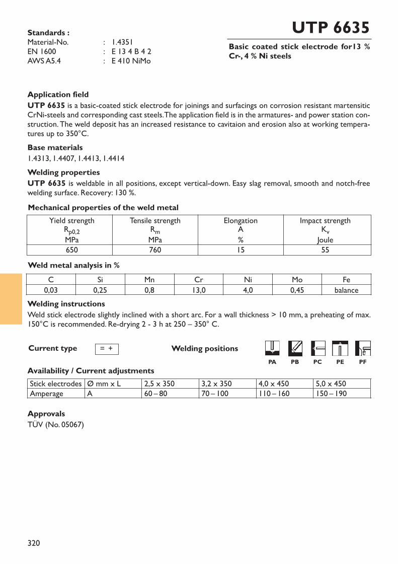
320
Basic coated stick electrode for13 %Cr-, 4 % Ni steels
UTP 6635Standards :Material-No. : 1.4351EN 1600 : E 13 4 B 4 2 AWS A5.4 : E 410 NiMo
Welding instructionsWeld stick electrode slightly inclined with a short arc. For a wall thickness > 10 mm, a preheating of max.150°C is recommended. Re-drying 2 - 3 h at 250 – 350° C.
Application fieldUTP 6635 is a basic-coated stick electrode for joinings and surfacings on corrosion resistant martensiticCrNi-steels and corresponding cast steels. The application field is in the armatures- and power station con-struction. The weld deposit has an increased resistance to cavitaion and erosion also at working tempera-tures up to 350°C.Base materials1.4313, 1.4407, 1.4413, 1.4414Welding propertiesUTP 6635 is weldable in all positions, except vertical-down. Easy slag removal, smooth and notch-freewelding surface. Recovery: 130 %.
Weld metal analysis in %
Yield strengthRp0,2MPa650
Tensile strengthRmMPa760
ElongationA%15
Impact strengthKvJoule55
Mechanical properties of the weld metal
Welding positionsCurrent type
Availability / Current adjustments
= +
C Si Mn Cr Ni Mo Fe0,03 0,25 0,8 13,0 4,0 0,45 balance
ApprovalsTÜV (No. 05067)
Stick electrodesAmperage
Ø mm x LA
2,5 x 35060 – 80
3,2 x 35070 – 100
4,0 x 450110 – 160
5,0 x 450150 – 190
PA PB PC PE PF
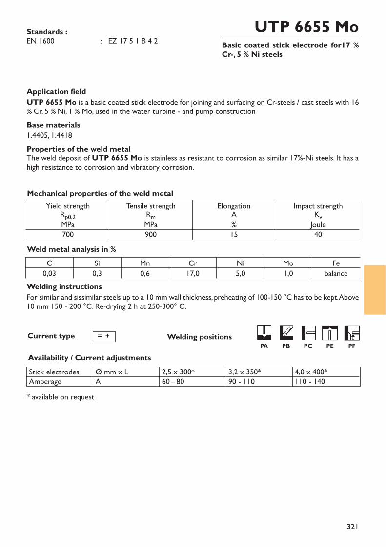
321
Basic coated stick electrode for17 %Cr-, 5 % Ni steels
UTP 6655 MoStandards :EN 1600 : EZ 17 5 1 B 4 2
Welding instructionsFor similar and sissimilar steels up to a 10 mm wall thickness, preheating of 100-150 °C has to be kept. Above10 mm 150 - 200 °C. Re-drying 2 h at 250-300° C.
Application fieldUTP 6655 Mo is a basic coated stick electrode for joining and surfacing on Cr-steels / cast steels with 16% Cr, 5 % Ni, 1 % Mo, used in the water turbine - and pump constructionBase materials1.4405, 1.4418Properties of the weld metalThe weld deposit of UTP 6655 Mo is stainless as resistant to corrosion as similar 17%-Ni steels. It has ahigh resistance to corrosion and vibratory corrosion.
Weld metal analysis in %
Yield strengthRp0,2MPa700
Tensile strengthRmMPa900
ElongationA%15
Impact strengthKvJoule40
Mechanical properties of the weld metal
Current type
Availability / Current adjustments
= +
C Si Mn Cr Ni Mo Fe0,03 0,3 0,6 17,0 5,0 1,0 balance
Stick electrodesAmperage
Ø mm x LA
2,5 x 300*60 – 80
3,2 x 350*90 - 110
4,0 x 400*110 - 140
* available on request
Welding positionsPA PB PC PE PF
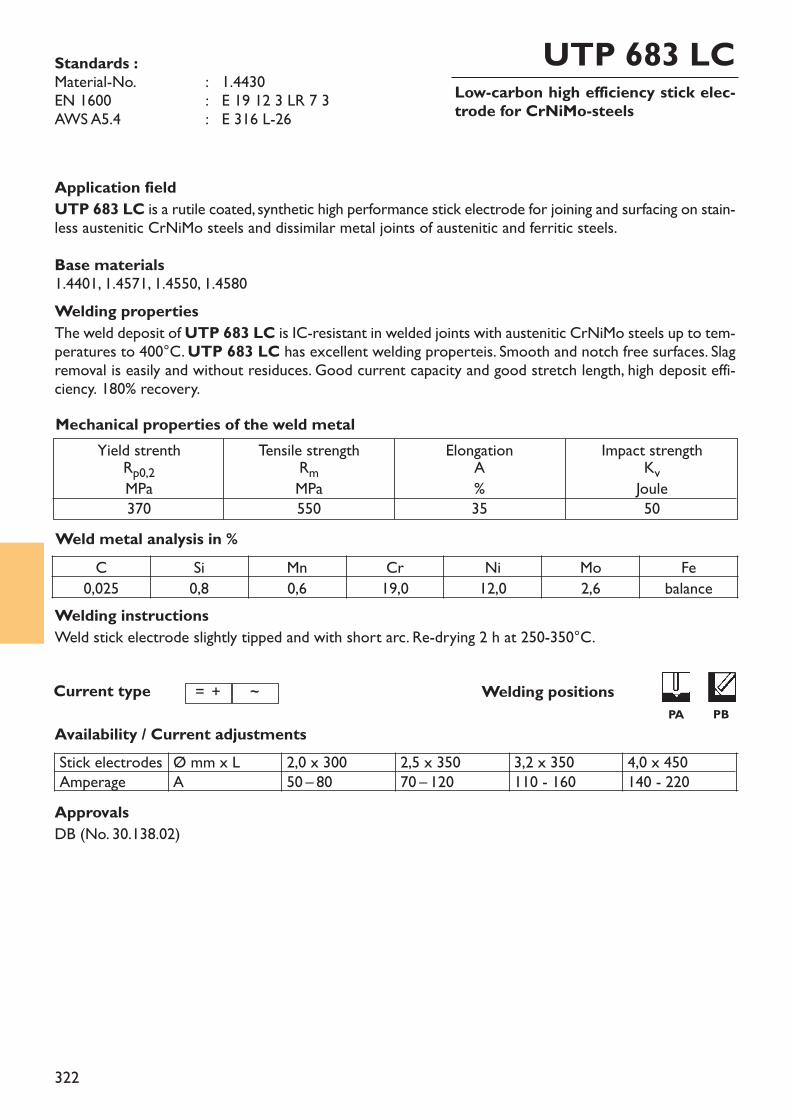
322
Low-carbon high efficiency stick elec-trode for CrNiMo-steels
UTP 683 LCStandards :Material-No. : 1.4430EN 1600 : E 19 12 3 LR 7 3AWS A5.4 : E 316 L-26
Welding instructionsWeld stick electrode slightly tipped and with short arc. Re-drying 2 h at 250-350°C.
Application fieldUTP 683 LC is a rutile coated, synthetic high performance stick electrode for joining and surfacing on stain-less austenitic CrNiMo steels and dissimilar metal joints of austenitic and ferritic steels. Base materials1.4401, 1.4571, 1.4550, 1.4580Welding propertiesThe weld deposit ofUTP 683 LC is IC-resistant in welded joints with austenitic CrNiMo steels up to tem-peratures to 400°C. UTP 683 LC has excellent welding properteis. Smooth and notch free surfaces. Slagremoval is easily and without residuces. Good current capacity and good stretch length, high deposit effi-ciency. 180% recovery.
Weld metal analysis in %
Yield strenthRp0,2MPa370
Tensile strengthRmMPa550
ElongationA%35
Impact strengthKvJoule50
Mechanical properties of the weld metal
Welding positionsCurrent type
Availability / Current adjustments
= +
C Si Mn Cr Ni Mo Fe0,025 0,8 0,6 19,0 12,0 2,6 balance
~
Stick electrodesAmperage
Ø mm x LA
2,0 x 30050 – 80
2,5 x 35070 – 120
3,2 x 350110 - 160
4,0 x 450140 - 220
ApprovalsDB (No. 30.138.02)
PA PB
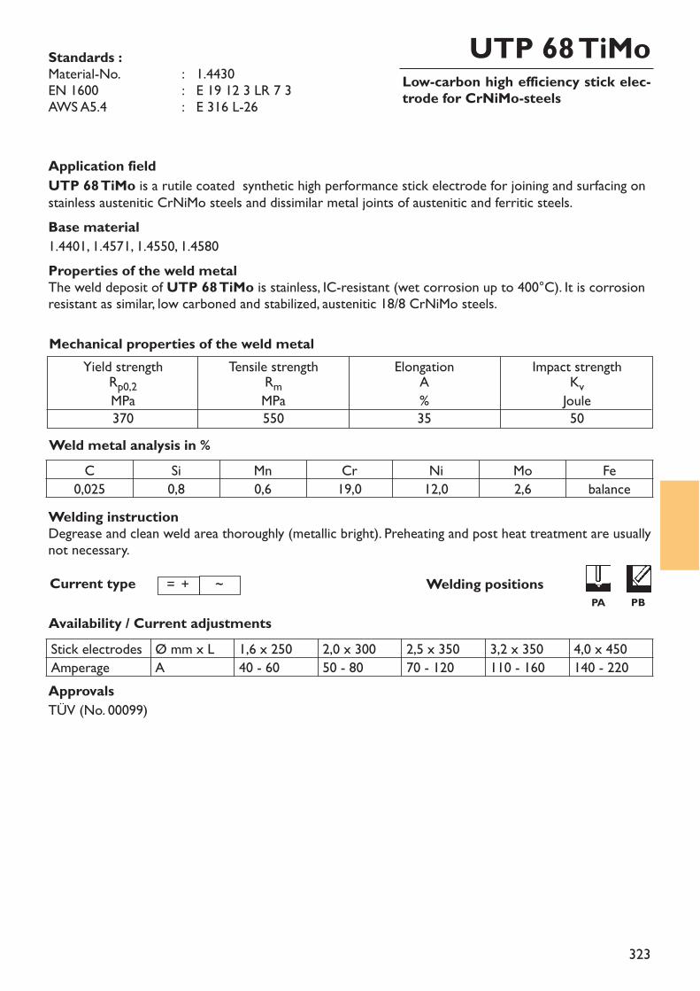
323
Low-carbon high efficiency stick elec-trode for CrNiMo-steels
UTP 68 TiMoStandards :Material-No. : 1.4430EN 1600 : E 19 12 3 LR 7 3AWS A5.4 : E 316 L-26
Application fieldUTP 68 TiMo is a rutile coated synthetic high performance stick electrode for joining and surfacing onstainless austenitic CrNiMo steels and dissimilar metal joints of austenitic and ferritic steels.Base material1.4401, 1.4571, 1.4550, 1.4580Properties of the weld metalThe weld deposit of UTP 68 TiMo is stainless, IC-resistant (wet corrosion up to 400°C). It is corrosionresistant as similar, low carboned and stabilized, austenitic 18/8 CrNiMo steels.
Weld metal analysis in %
Yield strengthRp0,2MPa370
Tensile strengthRmMPa550
ElongationA%35
Impact strengthKvJoule50
Mechanical properties of the weld metal
Welding positionsCurrent type
Availability / Current adjustments
= +
C Si Mn Cr Ni Mo Fe0,025 0,8 0,6 19,0 12,0 2,6 balance
~
ApprovalsTÜV (No. 00099)
Stick electrodes Ø mm x L 1,6 x 250 2,0 x 300 2,5 x 350 3,2 x 350 4,0 x 450Amperage A 40 - 60 50 - 80 70 - 120 110 - 160 140 - 220
Welding instructionDegrease and clean weld area thoroughly (metallic bright). Preheating and post heat treatment are usuallynot necessary.
PA PB
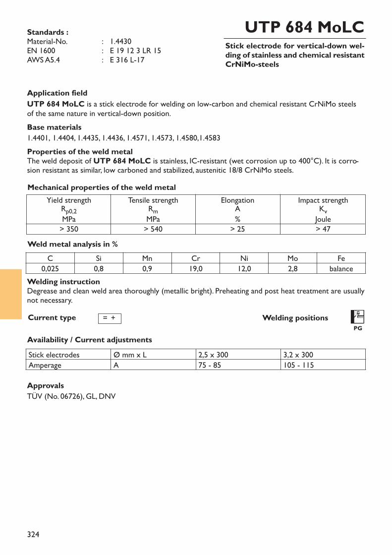
324
Stick electrode for vertical-down wel-ding of stainless and chemical resistantCrNiMo-steels
UTP 684 MoLCStandards :Material-No. : 1.4430EN 1600 : E 19 12 3 LR 15AWS A5.4 : E 316 L-17
Application fieldUTP 684 MoLC is a stick electrode for welding on low-carbon and chemical resistant CrNiMo steelsof the same nature in vertical-down position.Base materials1.4401, 1.4404, 1.4435, 1.4436, 1.4571, 1.4573, 1.4580,1.4583Properties of the weld metalThe weld deposit of UTP 684 MoLC is stainless, IC-resistant (wet corrosion up to 400°C). It is corro-sion resistant as similar, low carboned and stabilized, austenitic 18/8 CrNiMo steels.
Weld metal analysis in %
Yield strengthRp0,2MPa> 350
Tensile strengthRmMPa> 540
ElongationA%
> 25
Impact strengthKvJoule> 47
Mechanical properties of the weld metal
Welding positionsPG
Current type
Availability / Current adjustments
= +
C Si Mn Cr Ni Mo Fe0,025 0,8 0,9 19,0 12,0 2,8 balance
ApprovalsTÜV (No. 06726), GL, DNV
Stick electrodes Ø mm x L 2,5 x 300 3,2 x 300Amperage A 75 - 85 105 - 115
Welding instructionDegrease and clean weld area thoroughly (metallic bright). Preheating and post heat treatment are usuallynot necessary.
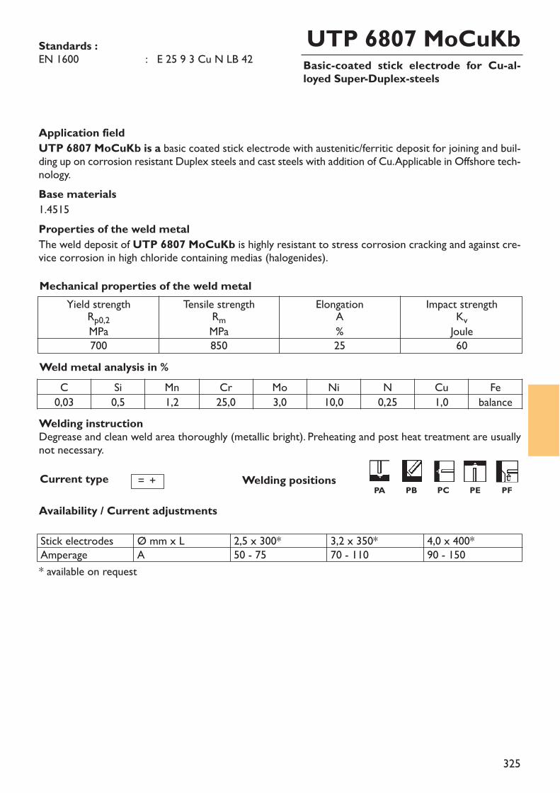
325
Basic-coated stick electrode for Cu-al-loyed Super-Duplex-steels
UTP 6807 MoCuKbStandards :EN 1600 : E 25 9 3 Cu N LB 42
Application fieldUTP 6807 MoCuKb is a basic coated stick electrode with austenitic/ferritic deposit for joining and buil-ding up on corrosion resistant Duplex steels and cast steels with addition of Cu. Applicable in Offshore tech-nology.Base materials1.4515Properties of the weld metalThe weld deposit of UTP 6807 MoCuKb is highly resistant to stress corrosion cracking and against cre-vice corrosion in high chloride containing medias (halogenides).
Weld metal analysis in %
Yield strengthRp0,2MPa700
Tensile strengthRmMPa850
ElongationA%25
Impact strengthKvJoule60
Mechanical properties of the weld metal
Current type
Availability / Current adjustments
= +
C Si Mn Cr Mo Ni N Cu Fe0,03 0,5 1,2 25,0 3,0 10,0 0,25 1,0 balance
Welding positions
Stick electrodesAmperage
Ø mm x LA
2,5 x 300*50 - 75
3,2 x 350*70 - 110
4,0 x 400*90 - 150
* available on request
Welding instructionDegrease and clean weld area thoroughly (metallic bright). Preheating and post heat treatment are usuallynot necessary.
PA PB PC PE PF
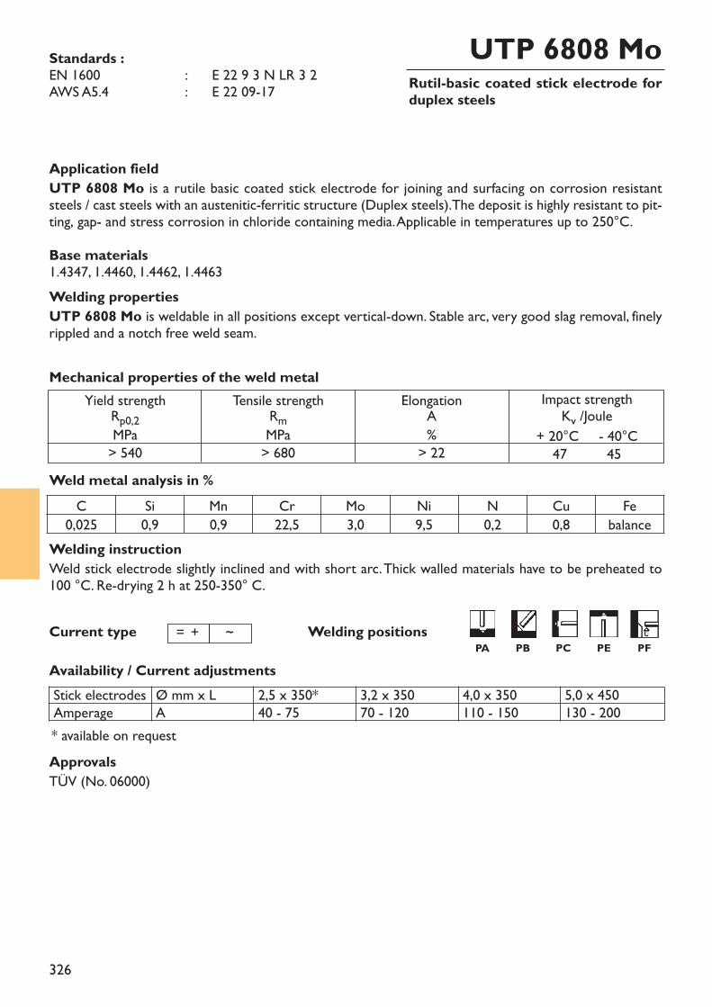
326
Rutil-basic coated stick electrode forduplex steels
UTP 6808 MoStandards :EN 1600 : ~ E 22 9 3 N LR 3 2 AWS A5.4 : ~ E 22 09-17
Welding instructionWeld stick electrode slightly inclined and with short arc. Thick walled materials have to be preheated to 100 °C. Re-drying 2 h at 250-350° C.
Application fieldUTP 6808 Mo is a rutile basic coated stick electrode for joining and surfacing on corrosion resistant steels / cast steels with an austenitic-ferritic structure (Duplex steels).The deposit is highly resistant to pit-ting, gap- and stress corrosion in chloride containing media. Applicable in temperatures up to 250°C.Base materials1.4347, 1.4460, 1.4462, 1.4463Welding propertiesUTP 6808 Mo is weldable in all positions except vertical-down. Stable arc, very good slag removal, finelyrippled and a notch free weld seam.
Weld metal analysis in %
Yield strengthRp0,2MPa> 540
Tensile strengthRmMPa> 680
ElongationA%
> 22
Impact strengthKv /Joule
+ 20°C - 40°C47 45
Mechanical properties of the weld metal
Current type
Availability / Current adjustments
C Si Mn Cr Mo Ni N Cu Fe0,025 0,9 0,9 22,5 3,0 9,5 0,2 0,8 balance
Welding positions
* available on requestApprovalsTÜV (No. 06000)
Stick electrodesAmperage
Ø mm x LA
2,5 x 350*40 - 75
3,2 x 35070 - 120
4,0 x 350110 - 150
5,0 x 450130 - 200
= + ~PA PB PC PE PF
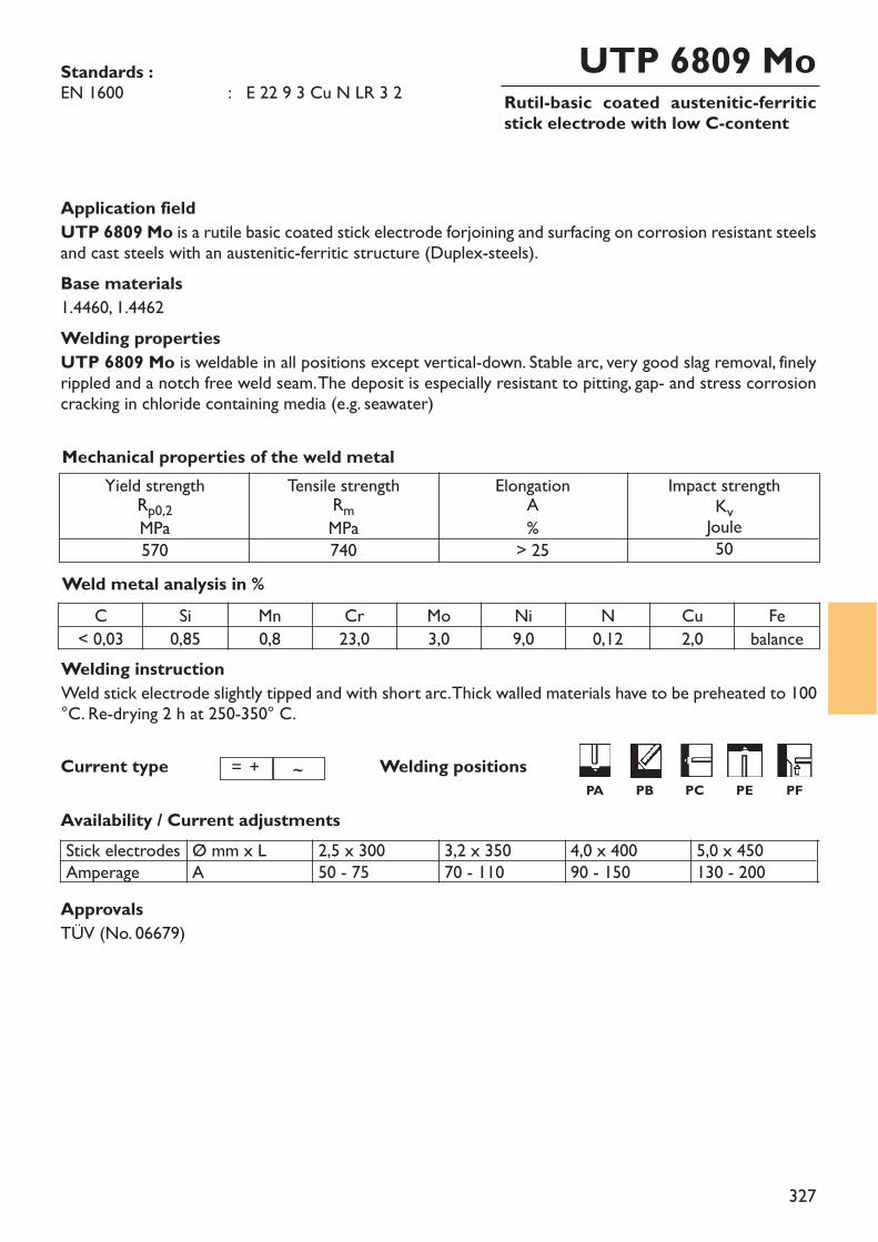
327
Rutil-basic coated austenitic-ferriticstick electrode with low C-content
UTP 6809 MoStandards :EN 1600 : E 22 9 3 Cu N LR 3 2
Welding instructionWeld stick electrode slightly tipped and with short arc. Thick walled materials have to be preheated to 100°C. Re-drying 2 h at 250-350° C.
Application fieldUTP 6809 Mo is a rutile basic coated stick electrode forjoining and surfacing on corrosion resistant steelsand cast steels with an austenitic-ferritic structure (Duplex-steels). Base materials1.4460, 1.4462Welding propertiesUTP 6809 Mo is weldable in all positions except vertical-down. Stable arc, very good slag removal, finelyrippled and a notch free weld seam. The deposit is especially resistant to pitting, gap- and stress corrosioncracking in chloride containing media (e.g. seawater)
Weld metal analysis in %
Yield strengthRp0,2MPa570
Tensile strengthRmMPa740
ElongationA%
> 25
Impact strengthKvJoule50
Mechanical properties of the weld metal
Current type
Availability / Current adjustments
C Si Mn Cr Mo Ni N Cu Fe< 0,03 0,85 0,8 23,0 3,0 9,0 0,12 2,0 balance
Welding positions
ApprovalsTÜV (No. 06679)
Stick electrodesAmperage
Ø mm x LA
2,5 x 30050 - 75
3,2 x 35070 - 110
4,0 x 40090 - 150
5,0 x 450130 - 200
= + ~PA PB PC PE PF
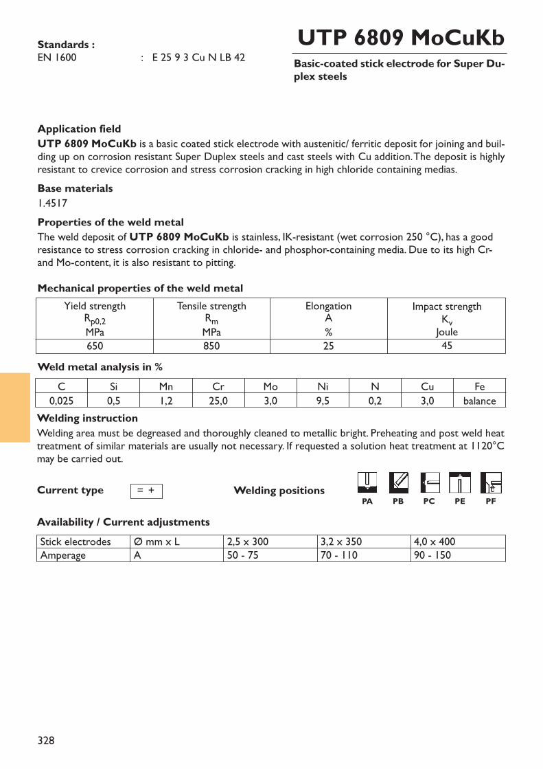
328
Basic-coated stick electrode for Super Du-plex steels
UTP 6809 MoCuKbStandards :EN 1600 : E 25 9 3 Cu N LB 42
Application fieldUTP 6809 MoCuKb is a basic coated stick electrode with austenitic/ ferritic deposit for joining and buil-ding up on corrosion resistant Super Duplex steels and cast steels with Cu addition. The deposit is highlyresistant to crevice corrosion and stress corrosion cracking in high chloride containing medias.Base materials1.4517Properties of the weld metalThe weld deposit of UTP 6809 MoCuKb is stainless, IK-resistant (wet corrosion 250 °C), has a goodresistance to stress corrosion cracking in chloride- and phosphor-containing media. Due to its high Cr-and Mo-content, it is also resistant to pitting.
Weld metal analysis in %
Yield strengthRp0,2MPa650
Tensile strengthRmMPa850
ElongationA%25
Impact strengthKvJoule45
Mechanical properties of the weld metal
Current type
Availability / Current adjustments
C Si Mn Cr Mo Ni N Cu Fe0,025 0,5 1,2 25,0 3,0 9,5 0,2 3,0 balance
Welding positions= +
Stick electrodesAmperage
Ø mm x LA
2,5 x 30050 - 75
3,2 x 35070 - 110
4,0 x 40090 - 150
Welding instructionWelding area must be degreased and thoroughly cleaned to metallic bright. Preheating and post weld heattreatment of similar materials are usually not necessary. If requested a solution heat treatment at 1120°Cmay be carried out.
PA PB PC PE PF
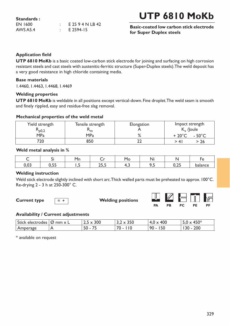
329
Basic-coated low carbon stick electrodefor Super Duplex steels
UTP 6810 MoKbStandards :EN 1600 : ~ E 25 9 4 N LB 42 AWS A5.4 : ~ E 2594-15
Welding instructionWeld stick electrode slightly inclined with short arc. Thick walled parts must be preheated to approx. 100°C.Re-drying 2 - 3 h at 250-300° C.
Application fieldUTP 6810 MoKb is a basic coated low-carbon stick electrode for joining and surfacing on high corrosionresistant steels and cast steels with austenitic-ferritic structure (Super-Duplex steels). The weld deposit hasa very good resistance in high chloride containing media.Base materials1.4460, 1.4463, 1.4468, 1.4469Welding propertiesUTP 6810 MoKb is weldable in all positions except vertical-down. Fine droplet. The weld seam is smoothand finely rippled, easy and residue-free slag removal.
Weld metal analysis in %
Yield strengthRp0,2MPa720
Tensile strengthRmMPa850
ElongationA%22
Impact strengthKv /Joule
+ 20°C - 50°C> 41 > 26
Mechanical properties of the weld metal
Current type
Availability / Current adjustments
Welding positions
Stick electrodesAmperage
Ø mm x LA
2,5 x 30050 - 75
3,2 x 35070 - 110
4,0 x 40090 - 150
5,0 x 450*130 - 200
= +
C Si Mn Cr Mo Ni N Fe0,03 0,55 1,5 25,5 4,3 9,5 0,25 balance
* available on request
PA PB PC PE PF
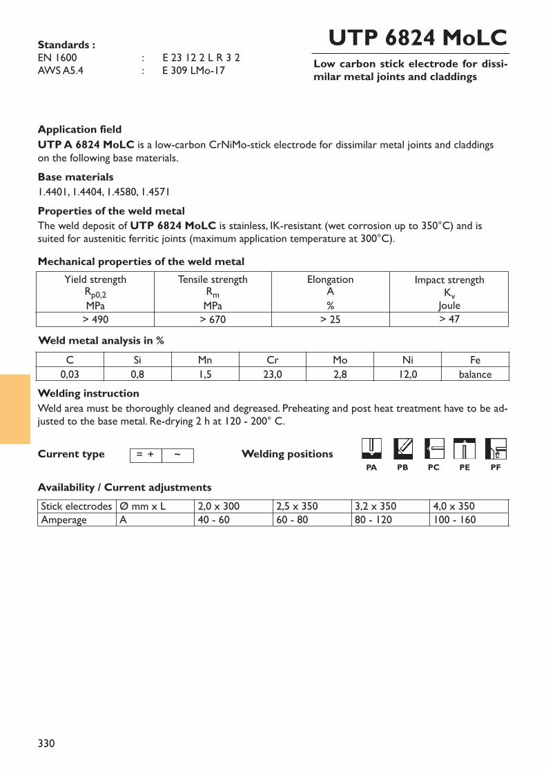
330
Low carbon stick electrode for dissi-milar metal joints and claddings
UTP 6824 MoLCStandards :EN 1600 : ~ E 23 12 2 L R 3 2 AWS A5.4 : E 309 LMo-17
Welding instructionWeld area must be thoroughly cleaned and degreased. Preheating and post heat treatment have to be ad-justed to the base metal. Re-drying 2 h at 120 - 200° C.
Application fieldUTP A 6824 MoLC is a low-carbon CrNiMo-stick electrode for dissimilar metal joints and claddingson the following base materials.Base materials1.4401, 1.4404, 1.4580, 1.4571Properties of the weld metalThe weld deposit of UTP 6824 MoLC is stainless, IK-resistant (wet corrosion up to 350°C) and issuited for austenitic ferritic joints (maximum application temperature at 300°C).
Weld metal analysis in %
Yield strengthRp0,2MPa> 490
Tensile strengthRmMPa> 670
ElongationA%
> 25
Impact strengthKvJoule> 47
Mechanical properties of the weld metal
Current type
Availability / Current adjustments
Welding positions
Stick electrodesAmperage
Ø mm x LA
2,0 x 30040 - 60
2,5 x 35060 - 80
3,2 x 35080 - 120
4,0 x 350100 - 160
= + ~
C Si Mn Cr Mo Ni Fe0,03 0,8 1,5 23,0 2,8 12,0 balance
PA PB PC PE PF
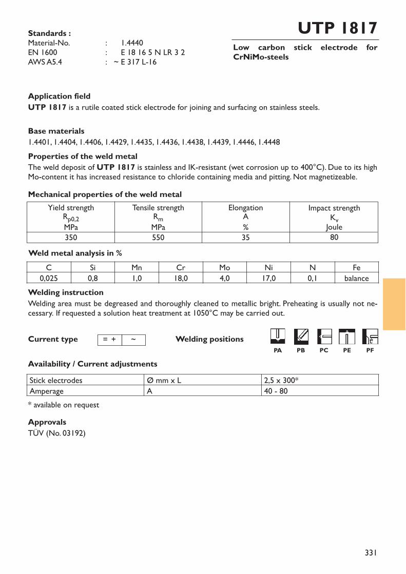
331
Low carbon stick electrode forCrNiMo-steels
UTP 1817Standards :Material-No. : ~ 1.4440EN 1600 : ~ E 18 16 5 N LR 3 2 AWS A5.4 : ~ E 317 L-16
Welding instructionWelding area must be degreased and thoroughly cleaned to metallic bright. Preheating is usually not ne-cessary. If requested a solution heat treatment at 1050°C may be carried out.
Application fieldUTP 1817 is a rutile coated stick electrode for joining and surfacing on stainless steels.
Base materials1.4401, 1.4404, 1.4406, 1.4429, 1.4435, 1.4436, 1.4438, 1.4439, 1.4446, 1.4448Properties of the weld metalThe weld deposit of UTP 1817 is stainless and IK-resistant (wet corrosion up to 400°C). Due to its highMo-content it has increased resistance to chloride containing media and pitting. Not magnetizeable.
Weld metal analysis in %
Yield strengthRp0,2MPa350
Tensile strengthRmMPa550
ElongationA%35
Impact strengthKvJoule80
Mechanical properties of the weld metal
Current type
Availability / Current adjustments
Welding positions= + ~
C Si Mn Cr Mo Ni N Fe0,025 0,8 1,0 18,0 4,0 17,0 0,1 balance
Stick electrodes Ø mm x L 2,5 x 300*Amperage A 40 - 80* available on requestApprovalsTÜV (No. 03192)
PA PB PC PE PF
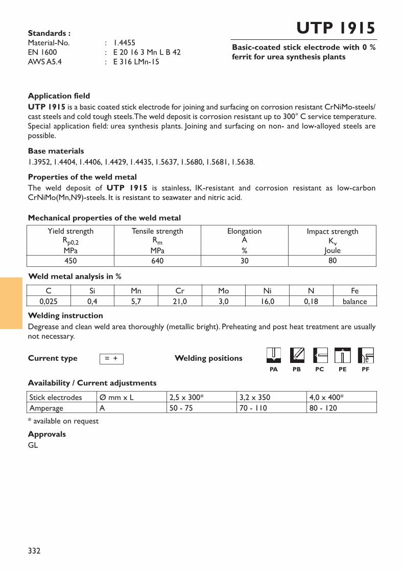
332
Basic-coated stick electrode with 0 %ferrit for urea synthesis plants
UTP 1915Standards :Material-No. : 1.4455EN 1600 : E 20 16 3 Mn L B 42AWS A5.4 : E 316 LMn-15
Welding instructionDegrease and clean weld area thoroughly (metallic bright). Preheating and post heat treatment are usuallynot necessary.
Application fieldUTP 1915 is a basic coated stick electrode for joining and surfacing on corrosion resistant CrNiMo-steels/cast steels and cold tough steels. The weld deposit is corrosion resistant up to 300° C service temperature.Special application field: urea synthesis plants. Joining and surfacing on non- and low-alloyed steels are possible.Base materials1.3952, 1.4404, 1.4406, 1.4429, 1.4435, 1.5637, 1.5680, 1.5681, 1.5638. Properties of the weld metalThe weld deposit of UTP 1915 is stainless, IK-resistant and corrosion resistant as low-carbonCrNiMo(Mn,N9)-steels. It is resistant to seawater and nitric acid.
Weld metal analysis in %
Yield strengthRp0,2MPa450
Tensile strengthRmMPa640
ElongationA%30
Impact strengthKvJoule80
Mechanical properties of the weld metal
Current type
Availability / Current adjustments
Welding positions= +
C Si Mn Cr Mo Ni N Fe0,025 0,4 5,7 21,0 3,0 16,0 0,18 balance
* available on request
Stick electrodes Ø mm x L 2,5 x 300* 3,2 x 350 4,0 x 400*Amperage A 50 - 75 70 - 110 80 - 120
ApprovalsGL
PA PB PC PE PF
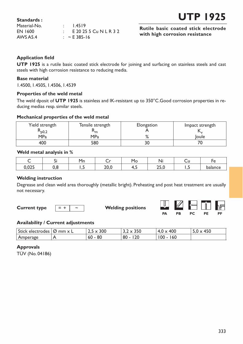
333
Rutile basic coated stick electrodewith high corrosion resistance
UTP 1925Standards :Material-No. : ~ 1.4519EN 1600 : ~ E 20 25 5 Cu N L R 3 2AWS A5.4 : ~ E 385-16
Application fieldUTP 1925 is a rutile basic coated stick electrode for joining and surfacing on stainless steels and caststeels with high corrosion resistance to reducing media.Base material1.4500, 1.4505, 1.4506, 1.4539Properties of the weld metalThe weld dposit of UTP 1925 is stainless and IK-resistant up to 350°C.Good corrosion properties in re-ducing medias resp. similar steels.
Weld metal analysis in %
Yield strengthRp0,2MPa400
Tensile strengthRmMPa580
ElongationA%30
Impact strengthKvJoule70
Mechanical properties of the weld metal
Current type
Availability / Current adjustments
Welding positions= + ~
C Si Mn Cr Mo Ni Cu Fe0,025 0,8 1,5 20,0 4,5 25,0 1,5 balance
Stick electrodesAmperage
Ø mm x LA
2,5 x 30060 - 80
3,2 x 35080 - 120
4,0 x 400100 - 160
5,0 x 450
ApprovalsTÜV (No. 04186)
Welding instructionDegrease and clean weld area thoroughly (metallic bright). Preheating and post heat treatment are usuallynot necessary.
PA PB PC PE PF
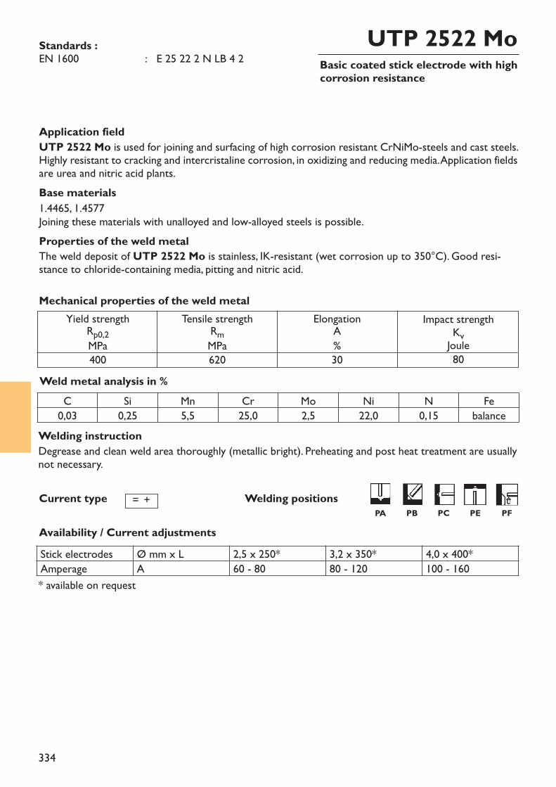
334
Basic coated stick electrode with highcorrosion resistance
UTP 2522 MoStandards :EN 1600 : E 25 22 2 N LB 4 2
Application fieldUTP 2522 Mo is used for joining and surfacing of high corrosion resistant CrNiMo-steels and cast steels.Highly resistant to cracking and intercristaline corrosion, in oxidizing and reducing media. Application fieldsare urea and nitric acid plants. Base materials1.4465, 1.4577Joining these materials with unalloyed and low-alloyed steels is possible.Properties of the weld metalThe weld deposit of UTP 2522 Mo is stainless, IK-resistant (wet corrosion up to 350°C). Good resi-stance to chloride-containing media, pitting and nitric acid.
Weld metal analysis in %
Yield strengthRp0,2MPa400
Tensile strengthRmMPa620
ElongationA%30
Impact strengthKvJoule80
Mechanical properties of the weld metal
Current type
Availability / Current adjustments
Welding positions= +
C Si Mn Cr Mo Ni N Fe0,03 0,25 5,5 25,0 2,5 22,0 0,15 balance
Stick electrodes Ø mm x L 2,5 x 250* 3,2 x 350* 4,0 x 400*Amperage A 60 - 80 80 - 120 100 - 160* available on request
Welding instructionDegrease and clean weld area thoroughly (metallic bright). Preheating and post heat treatment are usuallynot necessary.
PA PB PC PE PF
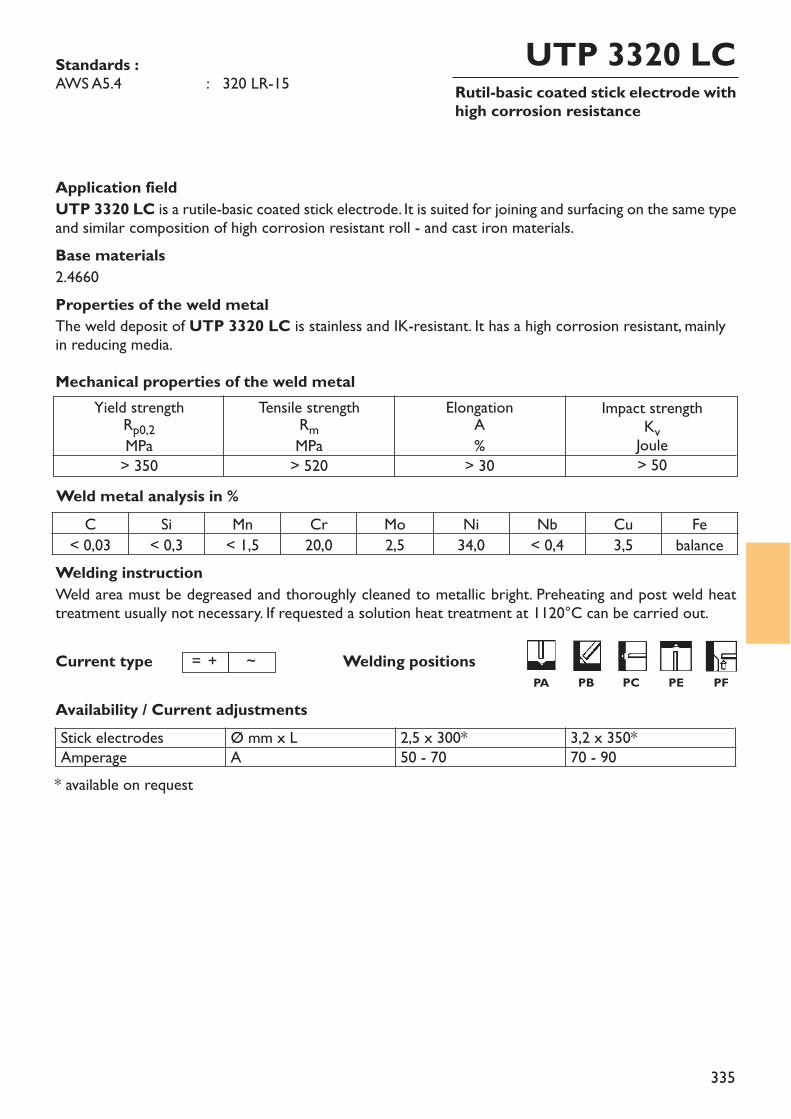
335
Rutil-basic coated stick electrode withhigh corrosion resistance
UTP 3320 LCStandards :AWS A5.4 : 320 LR-15
Welding instructionWeld area must be degreased and thoroughly cleaned to metallic bright. Preheating and post weld heattreatment usually not necessary. If requested a solution heat treatment at 1120°C can be carried out.
Application fieldUTP 3320 LC is a rutile-basic coated stick electrode. It is suited for joining and surfacing on the same typeand similar composition of high corrosion resistant roll - and cast iron materials.Base materials2.4660Properties of the weld metalThe weld deposit of UTP 3320 LC is stainless and IK-resistant. It has a high corrosion resistant, mainlyin reducing media.
Weld metal analysis in %
Yield strengthRp0,2MPa> 350
Tensile strengthRmMPa> 520
ElongationA%
> 30
Impact strengthKvJoule> 50
Mechanical properties of the weld metal
Current type
Availability / Current adjustments
Welding positions= + ~
Stick electrodesAmperage
Ø mm x LA
2,5 x 300*50 - 70
3,2 x 350*70 - 90
C Si Mn Cr Mo Ni Nb Cu Fe< 0,03 < 0,3 < 1,5 20,0 2,5 34,0 < 0,4 3,5 balance
* available on request
PA PB PC PE PF
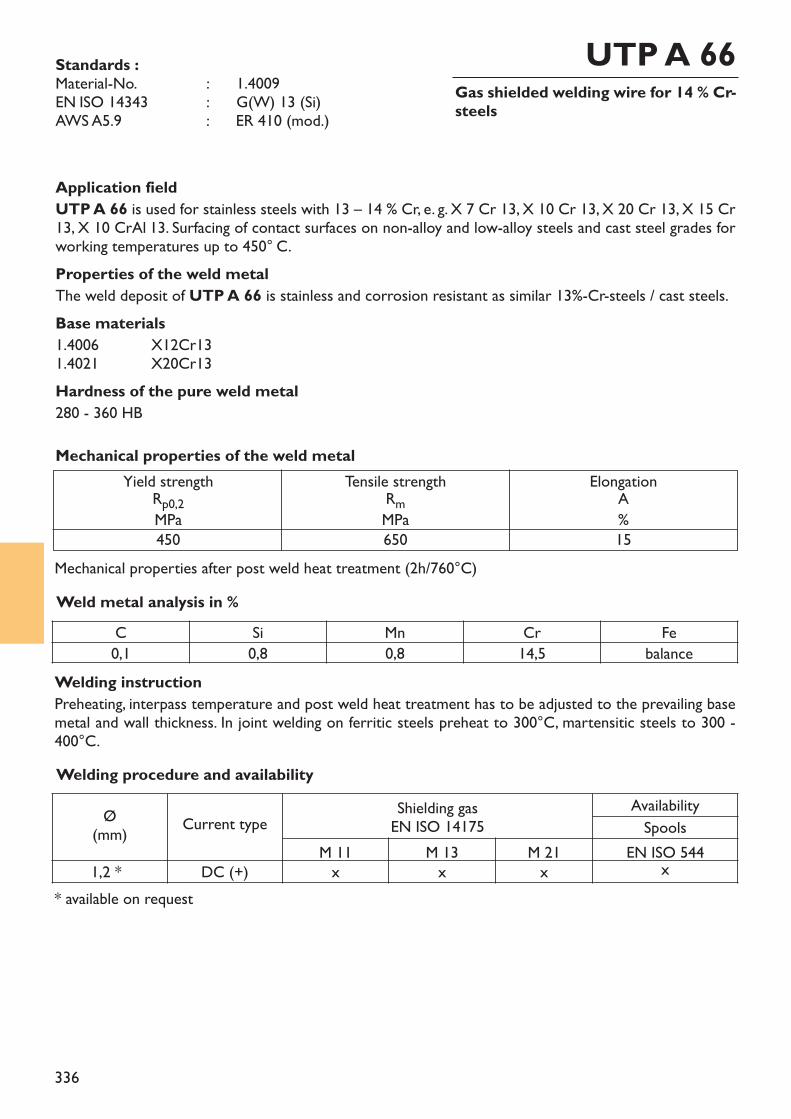
336
Gas shielded welding wire for 14 % Cr-steels
UTP A 66Standards :Material-No. : ~ 1.4009EN ISO 14343 : ~ G(W) 13 (Si)AWS A5.9 : ER 410 (mod.)
Application fieldUTP A 66 is used for stainless steels with 13 – 14 % Cr, e. g. X 7 Cr 13, X 10 Cr 13, X 20 Cr 13, X 15 Cr13, X 10 CrAl 13. Surfacing of contact surfaces on non-alloy and low-alloy steels and cast steel grades forworking temperatures up to 450° C.Properties of the weld metalThe weld deposit of UTP A 66 is stainless and corrosion resistant as similar 13%-Cr-steels / cast steels.Base materials1.4006 X12Cr131.4021 X20Cr13Hardness of the pure weld metal280 - 360 HB
Weld metal analysis in %
Yield strengthRp0,2MPa450
Tensile strengthRmMPa650
ElongationA%15
Mechanical properties of the weld metal
C Si Mn Cr Fe0,1 0,8 0,8 14,5 balance
* available on request
Ø(mm) Current type Shielding gas
EN ISO 14175AvailabilitySpools
M 11 M 13 M 21 EN ISO 5441,2 * DC (+) x x x x
Welding procedure and availability
Welding instructionPreheating, interpass temperature and post weld heat treatment has to be adjusted to the prevailing basemetal and wall thickness. In joint welding on ferritic steels preheat to 300°C, martensitic steels to 300 -400°C.
Mechanical properties after post weld heat treatment (2h/760°C)
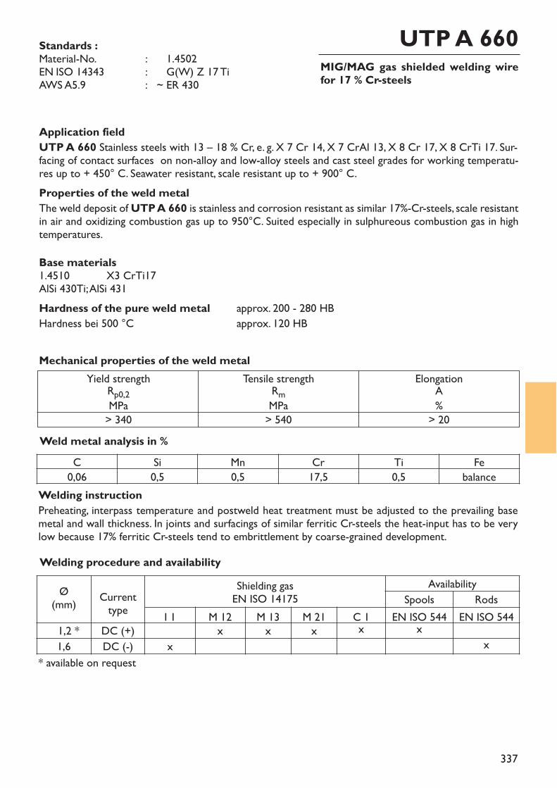
337
MIG/MAG gas shielded welding wirefor 17 % Cr-steels
UTP A 660Standards :Material-No. : ~ 1.4502EN ISO 14343 : ~ G(W) Z 17 TiAWS A5.9 : ~ ER 430
Application fieldUTP A 660 Stainless steels with 13 – 18 % Cr, e. g. X 7 Cr 14, X 7 CrAl 13, X 8 Cr 17, X 8 CrTi 17. Sur-facing of contact surfaces on non-alloy and low-alloy steels and cast steel grades for working temperatu-res up to + 450° C. Seawater resistant, scale resistant up to + 900° C.Properties of the weld metalThe weld deposit of UTP A 660 is stainless and corrosion resistant as similar 17%-Cr-steels, scale resistantin air and oxidizing combustion gas up to 950°C. Suited especially in sulphureous combustion gas in hightemperatures.Base materials1.4510 X3 CrTi17AlSi 430Ti; AlSi 431Hardness of the pure weld metal approx. 200 - 280 HBHardness bei 500 °C approx. 120 HB
Weld metal analysis in %
Yield strengthRp0,2MPa> 340
Tensile strengthRmMPa> 540
ElongationA%
> 20
Mechanical properties of the weld metal
* available on request
C Si Mn Cr Ti Fe0,06 0,5 0,5 17,5 0,5 balance
Ø(mm) Current
typeShielding gasEN ISO 14175
AvailabilitySpools Rods
I 1 M 12 M 13 M 21 C 1 EN ISO 544 EN ISO 5441,2 * DC (+) x x x x x1,6 DC (-) x x
Welding procedure and availability
Welding instructionPreheating, interpass temperature and postweld heat treatment must be adjusted to the prevailing basemetal and wall thickness. In joints and surfacings of similar ferritic Cr-steels the heat-input has to be verylow because 17% ferritic Cr-steels tend to embrittlement by coarse-grained development.
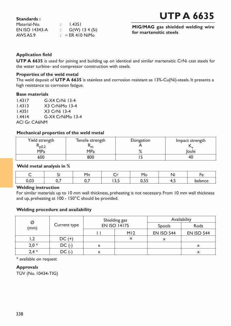
338
MIG/MAG gas shielded welding wirefor martensitic steels
UTP A 6635Standards :Material-No. : ~ 1.4351EN ISO 14343-A : ~ G(W) 13 4 (Si)AWS A5.9 : ~ ER 410 NiMo
Application fieldUTP A 6635 is used for joining and building up on identical and similar martensitic CrNi cast steels forthe water turbine- and compressor construction with steels.Properties of the weld metalThe weld deposit of UTP A 6635 is stainless and corrosion resistant as 13%-Cu(Ni)-steels. It presents ahigh resistance to corrosion fatigue. Base materials1.4317 G-X4 CrNi 13-41.4313 X3 CrNiMo 13-41.4351 X3 CrNi 13-41.4414 G-X4 CrNiMo 13-4ACl Gr. CA6NM
Weld metal analysis in %
Yield strengthRp0,2MPa600
Tensile strengthRmMPa800
ElongationA%15
Impact strengthKvJoule40
Mechanical properties of the weld metal
C Si Mn Cr Mo Ni Fe0,03 0,7 0,7 13,5 0,55 4,5 balance
* available on requestApprovalsTÜV (No. 10434-TIG)
Welding instructionFor similar materials up to 10 mm wall thickness, preheating is not necessary. From 10 mm wall thicknessand up, preheating at 100 - 150°C should be provided.Welding procedure and availability
Ø(mm) Current type Shielding gas
EN ISO 14175Availability
Spools RodsI 1 M12 EN ISO 544 EN ISO 544
1,2 DC (+) x x2,0 * DC (-) x x2,4 * DC (-) x x
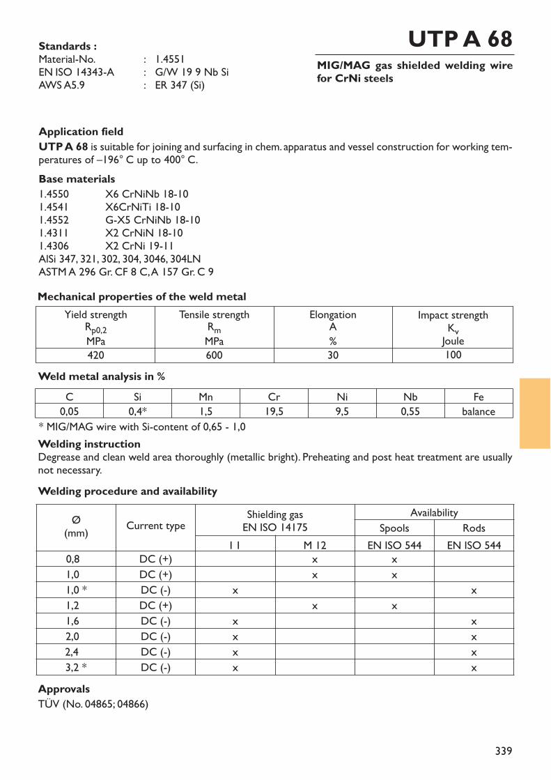
339
MIG/MAG gas shielded welding wirefor CrNi steels
UTP A 68Standards :Material-No. : 1.4551EN ISO 14343-A : G/W 19 9 Nb SiAWS A5.9 : ER 347 (Si)
Application fieldUTP A 68 is suitable for joining and surfacing in chem. apparatus and vessel construction for working tem-peratures of –196° C up to 400° C.Base materials1.4550 X6 CrNiNb 18-101.4541 X6CrNiTi 18-101.4552 G-X5 CrNiNb 18-101.4311 X2 CrNiN 18-101.4306 X2 CrNi 19-11AlSi 347, 321, 302, 304, 3046, 304LNASTM A 296 Gr. CF 8 C, A 157 Gr. C 9
Weld metal analysis in %
Yield strengthRp0,2MPa420
Tensile strengthRmMPa600
ElongationA%30
Impact strengthKvJoule100
Mechanical properties of the weld metal
C Si Mn Cr Ni Nb Fe0,05 0,4* 1,5 19,5 9,5 0,55 balance
ApprovalsTÜV (No. 04865; 04866)
* MIG/MAG wire with Si-content of 0,65 - 1,0Welding instructionDegrease and clean weld area thoroughly (metallic bright). Preheating and post heat treatment are usuallynot necessary.Welding procedure and availability
Ø(mm) Current type Shielding gas
EN ISO 14175Availability
Spools RodsI 1 M 12 EN ISO 544 EN ISO 544
0,8 DC (+) x x1,0 DC (+) x x1,0 * DC (-) x x1,2 DC (+) x x1,6 DC (-) x x2,0 DC (-) x x2,4 DC (-) x x3,2 * DC (-) x x
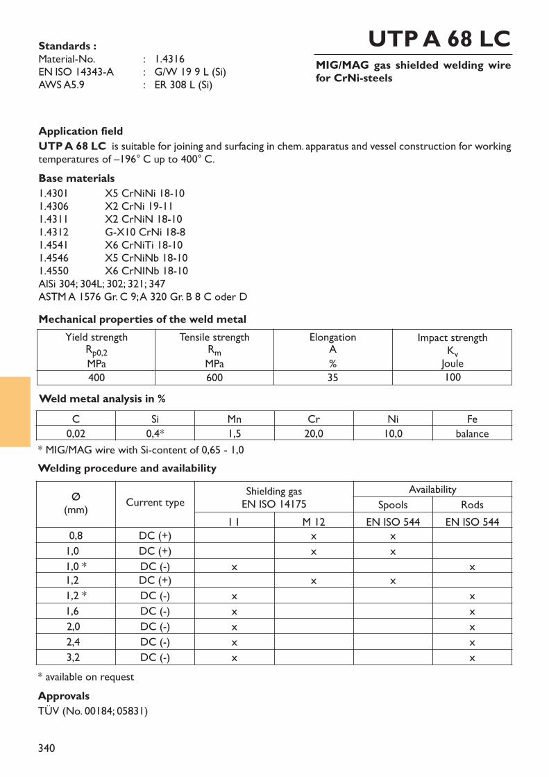
340
MIG/MAG gas shielded welding wirefor CrNi-steels
UTP A 68 LCStandards :Material-No. : 1.4316EN ISO 14343-A : G/W 19 9 L (Si)AWS A5.9 : ER 308 L (Si)
Application fieldUTP A 68 LC is suitable for joining and surfacing in chem. apparatus and vessel construction for workingtemperatures of –196° C up to 400° C.Base materials1.4301 X5 CrNiNi 18-101.4306 X2 CrNi 19-111.4311 X2 CrNiN 18-101.4312 G-X10 CrNi 18-81.4541 X6 CrNiTi 18-101.4546 X5 CrNiNb 18-10 1.4550 X6 CrNINb 18-10AlSi 304; 304L; 302; 321; 347ASTM A 1576 Gr. C 9; A 320 Gr. B 8 C oder D
Weld metal analysis in %
Yield strengthRp0,2MPa400
Tensile strengthRmMPa600
ElongationA%35
Impact strengthKvJoule100
Mechanical properties of the weld metal
* available on requestApprovalsTÜV (No. 00184; 05831)
C Si Mn Cr Ni Fe0,02 0,4* 1,5 20,0 10,0 balance
* MIG/MAG wire with Si-content of 0,65 - 1,0Welding procedure and availability
Ø(mm) Current type Shielding gas
EN ISO 14175Availability
Spools RodsI 1 M 12 EN ISO 544 EN ISO 544
0,8 DC (+) x x1,0 DC (+) x x1,0 * DC (-) x x1,2 DC (+) x x1,2 * DC (-) x x1,6 DC (-) x x2,0 DC (-) x x2,4 DC (-) x x3,2 DC (-) x x
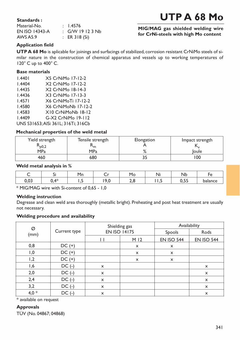
341
MIG/MAG gas shielded welding wirefor CrNi-steels with high Mo content
UTP A 68 MoStandards :Material-No. : 1.4576EN ISO 14343-A : G/W 19 12 3 NbAWS A5.9 : ER 318 (Si)Application fieldUTP A 68 Mo is aplicable for joinings and surfacings of stabilized, corrosion resistant CrNiMo steels of si-milar nature in the construction of chemical apparatus and vessels up to working temperatures of 120° C up to 400° C.Base materials1.4401 X5 CrNiMo 17-12-21.4404 X2 CrNiMo 17-12-21.4435 X2 CrNiMo 18-14-31.4436 X3 CrNiMo 17-13-31.4571 X6 CrNiMoTi 17-12-21.4580 X6 CrNiMoNb 17-12-21.4583 X10 CrNiMoNb 18-121.4409 G-X2 CrNiMo 19-112UNS S31653; AlSi 361L; 316Ti; 316Cb
Weld metal analysis in %
Yield strengthRp0,2MPa460
Tensile strengthRmMPa680
ElongationA%35
Impact strengthKvJoule100
Mechanical properties of the weld metal
* available on requestApprovalsTÜV (No. 04867; 04868)
C Si Mn Cr Mo Ni Nb Fe0,03 0,4* 1,5 19,0 2,8 11,5 0,55 balance
* MIG/MAG wire with Si-content of 0,65 - 1,0
Welding procedure and availability
Ø(mm) Current type Shielding gas
EN ISO 14175Availability
Spools RodsI 1 M 12 EN ISO 544 EN ISO 544
0,8 DC (+) x x1,0 DC (+) x x1,2 DC (+) x x1,6 DC (-) x x2,0 DC (-) x x2,4 DC (-) x x3,2 DC (-) x x4,0 * DC (-) x x
Welding instructionDegrease and clean weld area thoroughly (metallic bright). Preheating and post heat treatment are usuallynot necessary.
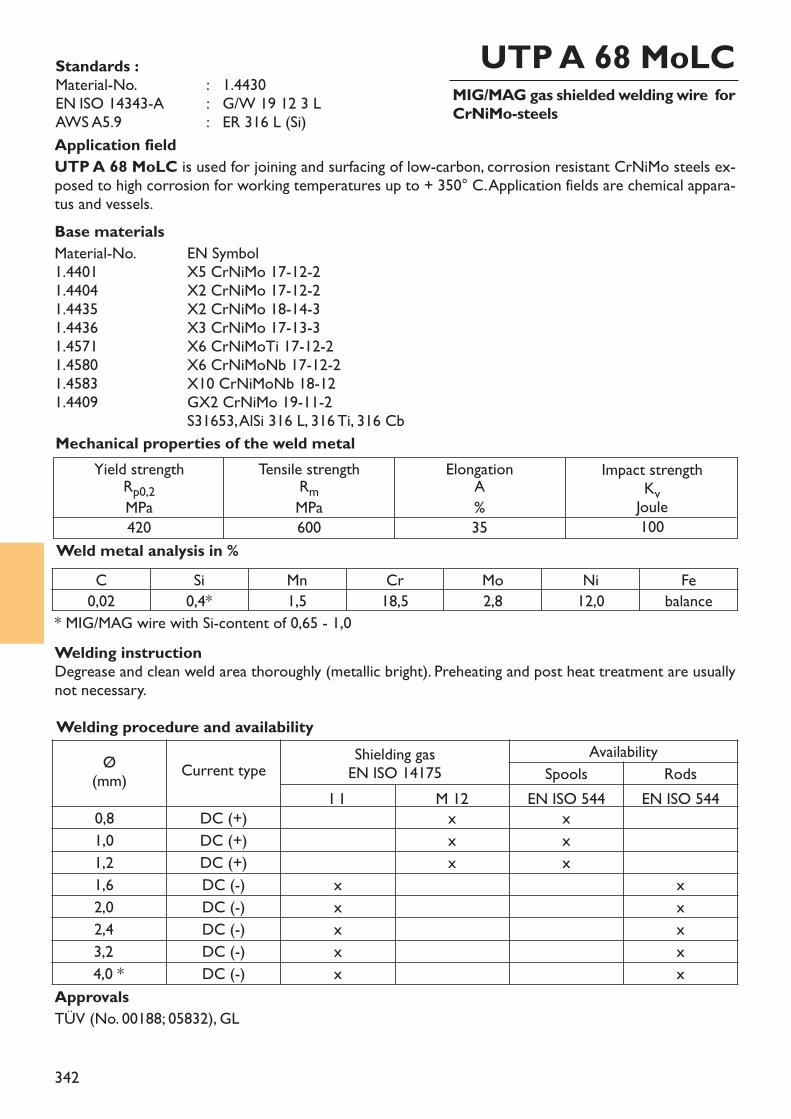
342
MIG/MAG gas shielded welding wire forCrNiMo-steels
UTP A 68 MoLCStandards :Material-No. : 1.4430EN ISO 14343-A : G/W 19 12 3 LAWS A5.9 : ER 316 L (Si)Application fieldUTP A 68 MoLC is used for joining and surfacing of low-carbon, corrosion resistant CrNiMo steels ex-posed to high corrosion for working temperatures up to + 350° C. Application fields are chemical appara-tus and vessels.Base materialsMaterial-No. EN Symbol1.4401 X5 CrNiMo 17-12-21.4404 X2 CrNiMo 17-12-21.4435 X2 CrNiMo 18-14-31.4436 X3 CrNiMo 17-13-31.4571 X6 CrNiMoTi 17-12-21.4580 X6 CrNiMoNb 17-12-21.4583 X10 CrNiMoNb 18-121.4409 GX2 CrNiMo 19-11-2
S31653, AlSi 316 L, 316 Ti, 316 Cb
Weld metal analysis in %
Yield strengthRp0,2MPa420
Tensile strengthRmMPa600
ElongationA%35
Impact strengthKvJoule100
Mechanical properties of the weld metal
ApprovalsTÜV (No. 00188; 05832), GL
C Si Mn Cr Mo Ni Fe0,02 0,4* 1,5 18,5 2,8 12,0 balance
* MIG/MAG wire with Si-content of 0,65 - 1,0
Welding procedure and availabilityØ
(mm) Current type Shielding gasEN ISO 14175
AvailabilitySpools Rods
I 1 M 12 EN ISO 544 EN ISO 5440,8 DC (+) x x1,0 DC (+) x x1,2 DC (+) x x1,6 DC (-) x x2,0 DC (-) x x2,4 DC (-) x x3,2 DC (-) x x4,0 * DC (-) x x
Welding instructionDegrease and clean weld area thoroughly (metallic bright). Preheating and post heat treatment are usuallynot necessary.
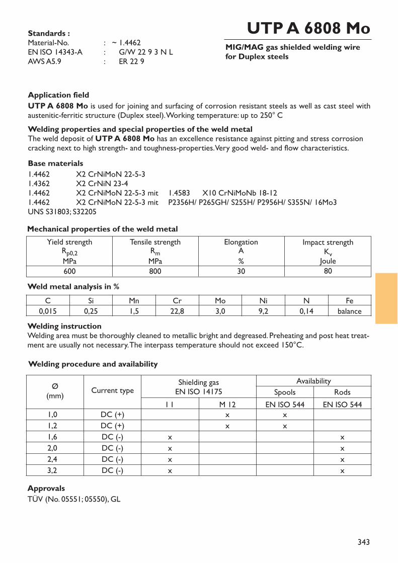
343
MIG/MAG gas shielded welding wirefor Duplex steels
UTP A 6808 MoStandards :Material-No. : ~ 1.4462EN ISO 14343-A : ~ G/W 22 9 3 N LAWS A5.9 : ~ ER 22 9
Application fieldUTP A 6808 Mo is used for joining and surfacing of corrosion resistant steels as well as cast steel withaustenitic-ferritic structure (Duplex steel). Working temperature: up to 250° CWelding properties and special properties of the weld metalThe weld deposit of UTP A 6808 Mo has an excellence resistance against pitting and stress corrosioncracking next to high strength- and toughness-properties. Very good weld- and flow characteristics.Base materials1.4462 X2 CrNiMoN 22-5-31.4362 X2 CrNiN 23-41.4462 X2 CrNiMoN 22-5-3 mit 1.4583 X10 CrNiMoNb 18-121.4462 X2 CrNiMoN 22-5-3 mit P2356H/ P265GH/ S255H/ P2956H/ S355N/ 16Mo3UNS S31803; S32205
Weld metal analysis in %
Yield strengthRp0,2MPa600
Tensile strengthRmMPa800
ElongationA%30
Impact strengthKvJoule80
Mechanical properties of the weld metal
ApprovalsTÜV (No. 05551; 05550), GL
C Si Mn Cr Mo Ni N Fe0,015 0,25 1,5 22,8 3,0 9,2 0,14 balance
Welding instructionWelding area must be thoroughly cleaned to metallic bright and degreased. Preheating and post heat treat-ment are usually not necessary. The interpass temperature should not exceed 150°C.Welding procedure and availability
Ø(mm) Current type Shielding gas
EN ISO 14175Availability
Spools RodsI 1 M 12 EN ISO 544 EN ISO 544
1,0 DC (+) x x1,2 DC (+) x x1,6 DC (-) x x2,0 DC (-) x x2,4 DC (-) x x3,2 DC (-) x x
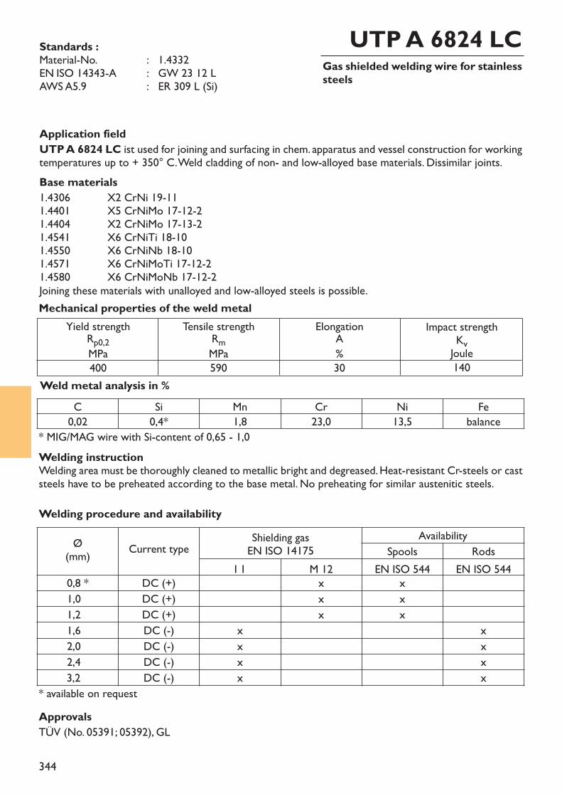
344
Gas shielded welding wire for stainlesssteels
UTP A 6824 LCStandards :Material-No. : 1.4332EN ISO 14343-A : GW 23 12 LAWS A5.9 : ER 309 L (Si)
Application fieldUTP A 6824 LC ist used for joining and surfacing in chem. apparatus and vessel construction for workingtemperatures up to + 350° C. Weld cladding of non- and low-alloyed base materials. Dissimilar joints. Base materials1.4306 X2 CrNi 19-111.4401 X5 CrNiMo 17-12-21.4404 X2 CrNiMo 17-13-21.4541 X6 CrNiTi 18-101.4550 X6 CrNiNb 18-101.4571 X6 CrNiMoTi 17-12-21.4580 X6 CrNiMoNb 17-12-2Joining these materials with unalloyed and low-alloyed steels is possible.
Weld metal analysis in %
Yield strengthRp0,2MPa400
Tensile strengthRmMPa590
ElongationA%30
Impact strengthKvJoule140
Mechanical properties of the weld metal
ApprovalsTÜV (No. 05391; 05392), GL
* MIG/MAG wire with Si-content of 0,65 - 1,0C Si Mn Cr Ni Fe
0,02 0,4* 1,8 23,0 13,5 balance
* available on request
Welding instructionWelding area must be thoroughly cleaned to metallic bright and degreased. Heat-resistant Cr-steels or caststeels have to be preheated according to the base metal. No preheating for similar austenitic steels.Welding procedure and availability
Ø(mm) Current type Shielding gas
EN ISO 14175Availability
Spools RodsI 1 M 12 EN ISO 544 EN ISO 544
0,8 * DC (+) x x1,0 DC (+) x x1,2 DC (+) x x1,6 DC (-) x x2,0 DC (-) x x2,4 DC (-) x x3,2 DC (-) x x
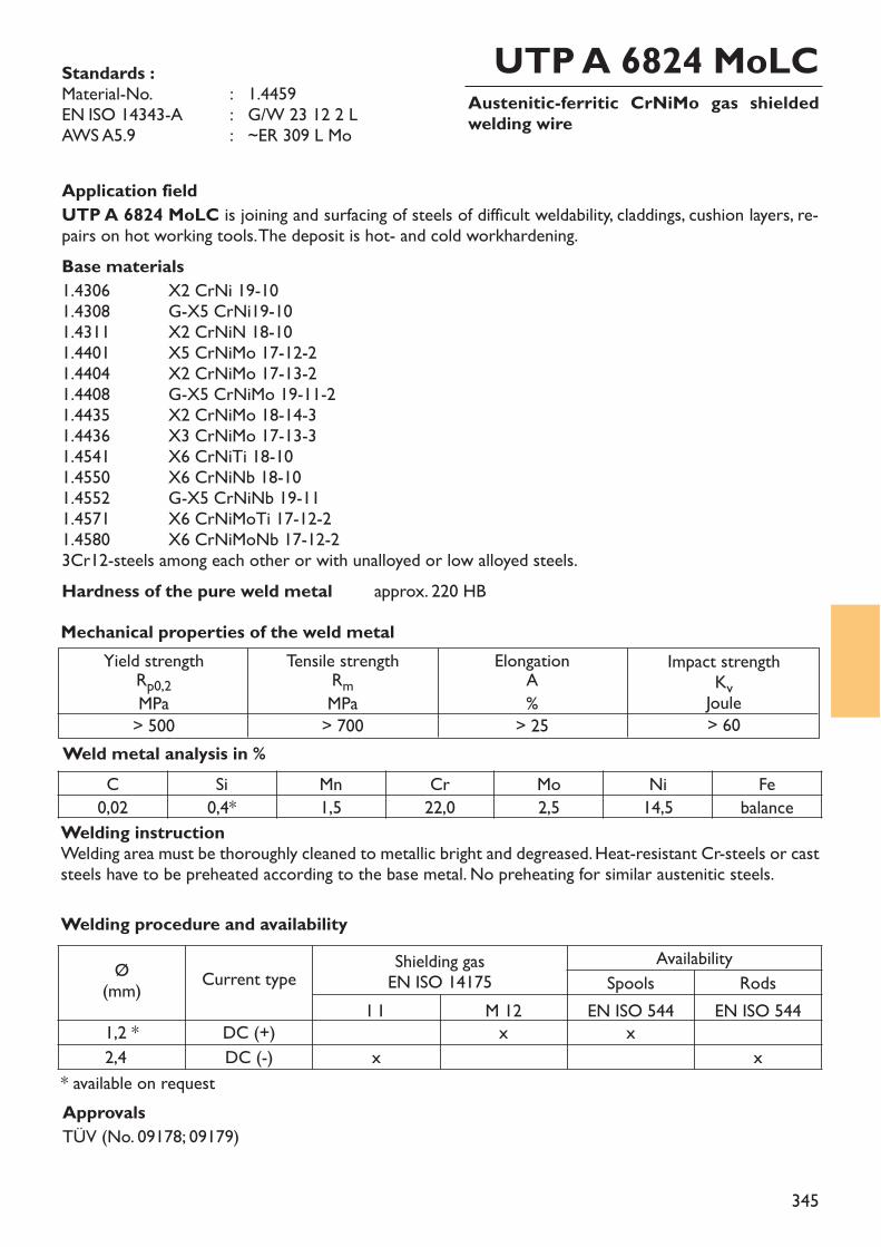
345
Austenitic-ferritic CrNiMo gas shieldedwelding wire
UTP A 6824 MoLCStandards :Material-No. : 1.4459EN ISO 14343-A : G/W 23 12 2 L AWS A5.9 : ~ER 309 L Mo
Application fieldUTP A 6824 MoLC is joining and surfacing of steels of difficult weldability, claddings, cushion layers, re-pairs on hot working tools. The deposit is hot- and cold workhardening. Base materials1.4306 X2 CrNi 19-101.4308 G-X5 CrNi19-101.4311 X2 CrNiN 18-101.4401 X5 CrNiMo 17-12-21.4404 X2 CrNiMo 17-13-21.4408 G-X5 CrNiMo 19-11-21.4435 X2 CrNiMo 18-14-31.4436 X3 CrNiMo 17-13-31.4541 X6 CrNiTi 18-101.4550 X6 CrNiNb 18-101.4552 G-X5 CrNiNb 19-111.4571 X6 CrNiMoTi 17-12-21.4580 X6 CrNiMoNb 17-12-23Cr12-steels among each other or with unalloyed or low alloyed steels.Hardness of the pure weld metal approx. 220 HB
Weld metal analysis in %
Yield strengthRp0,2MPa> 500
Tensile strengthRmMPa> 700
ElongationA%
> 25
Impact strengthKvJoule> 60
Mechanical properties of the weld metal
ApprovalsTÜV (No. 09178; 09179)
C Si Mn Cr Mo Ni Fe0,02 0,4* 1,5 22,0 2,5 14,5 balance
* available on request
Welding procedure and availability
Ø(mm) Current type Shielding gas
EN ISO 14175Availability
Spools RodsI 1 M 12 EN ISO 544 EN ISO 544
1,2 * DC (+) x x2,4 DC (-) x x
Welding instructionWelding area must be thoroughly cleaned to metallic bright and degreased. Heat-resistant Cr-steels or caststeels have to be preheated according to the base metal. No preheating for similar austenitic steels.
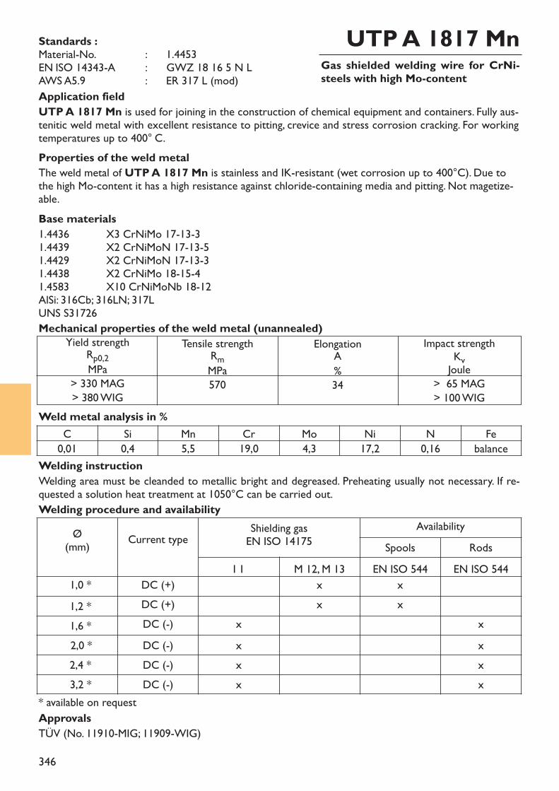
346
Gas shielded welding wire for CrNi-steels with high Mo-content
UTP A 1817 MnStandards :Material-No. : 1.4453EN ISO 14343-A : ~ GWZ 18 16 5 N LAWS A5.9 : ER 317 L (mod)Application fieldUTP A 1817 Mn is used for joining in the construction of chemical equipment and containers. Fully aus-tenitic weld metal with excellent resistance to pitting, crevice and stress corrosion cracking. For workingtemperatures up to 400° C.Properties of the weld metalThe weld metal of UTP A 1817 Mn is stainless and IK-resistant (wet corrosion up to 400°C). Due tothe high Mo-content it has a high resistance against chloride-containing media and pitting. Not magetize-able.Base materials1.4436 X3 CrNiMo 17-13-31.4439 X2 CrNiMoN 17-13-51.4429 X2 CrNiMoN 17-13-31.4438 X2 CrNiMo 18-15-41.4583 X10 CrNiMoNb 18-12AlSi: 316Cb; 316LN; 317LUNS S31726
Weld metal analysis in %
Mechanical properties of the weld metal (unannealed)
* available on request
C Si Mn Cr Mo Ni N Fe0,01 0,4 5,5 19,0 4,3 17,2 0,16 balance
Welding procedure and availability
Welding instructionWelding area must be cleanded to metallic bright and degreased. Preheating usually not necessary. If re-quested a solution heat treatment at 1050°C can be carried out.
Yield strengthRp0,2MPa> 330 MAG> 380 WIG
Tensile strengthRmMPa570
ElongationA%34
Impact strengthKvJoule
> 65 MAG> 100 WIG
Ø(mm) Current type Shielding gas
EN ISO 14175Availability
Spools RodsI 1 M 12, M 13 EN ISO 544 EN ISO 544
1,0 * DC (+) x x1,2 * DC (+) x x1,6 * DC (-) x x2,0 * DC (-) x x2,4 * DC (-) x x3,2 * DC (-) x x
ApprovalsTÜV (No. 11910-MIG; 11909-WIG)
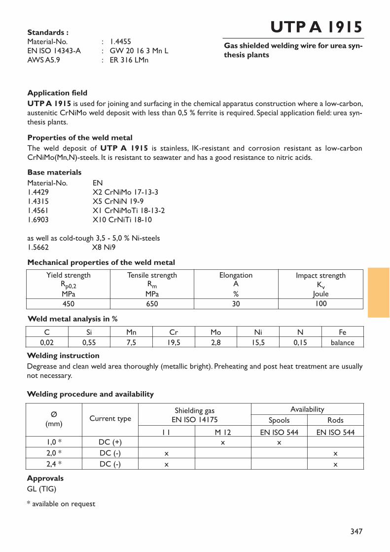
347
Gas shielded welding wire for urea syn-thesis plants
UTP A 1915Standards :Material-No. : 1.4455EN ISO 14343-A : GW 20 16 3 Mn LAWS A5.9 : ER 316 LMn
Application fieldUTP A 1915 is used for joining and surfacing in the chemical apparatus construction where a low-carbon,austenitic CrNiMo weld deposit with less than 0,5 % ferrite is required. Special application field: urea syn-thesis plants.Properties of the weld metalThe weld deposit of UTP A 1915 is stainless, IK-resistant and corrosion resistant as low-carbonCrNiMo(Mn,N)-steels. It is resistant to seawater and has a good resistance to nitric acids.Base materialsMaterial-No. EN1.4429 X2 CrNiMo 17-13-31.4315 X5 CrNiN 19-91.4561 X1 CrNiMoTi 18-13-21.6903 X10 CrNiTi 18-10as well as cold-tough 3,5 - 5,0 % Ni-steels1.5662 X8 Ni9
Weld metal analysis in %
Yield strengthRp0,2MPa450
Tensile strengthRmMPa650
ElongationA%30
Impact strengthKvJoule100
Mechanical properties of the weld metal
* available on request
C Si Mn Cr Mo Ni N Fe0,02 0,55 7,5 19,5 2,8 15,5 0,15 balance
Welding procedure and availability
Ø(mm) Current type Shielding gas
EN ISO 14175Availability
Spools RodsI 1 M 12 EN ISO 544 EN ISO 544
1,0 * DC (+) x x2,0 * DC (-) x x2,4 * DC (-) x x
ApprovalsGL (TIG)
Welding instructionDegrease and clean weld area thoroughly (metallic bright). Preheating and post heat treatment are usuallynot necessary.
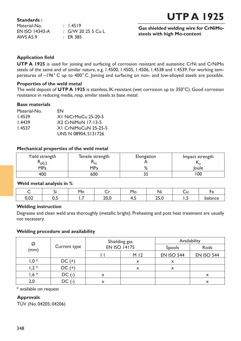
348
Gas shielded welding wire for CrNiMo-steels with high Mo-content
UTP A 1925Standards :Material-No. : 1.4519EN ISO 14343-A : G/W 20 25 5 Cu LAWS A5.9 : ER 385
Application fieldUTP A 1925 is used for joining and surfacing of corrosion resistant and austenitic CrNi and CrNiMosteels of the same and of similar nature, e.g. 1.4500, 1.4505, 1.4506, 1.4538 and 1.4539. For working tem-peratures of –196° C up to 400° C. Joining and surfacing on non- and low-alloyed steels are possible.Properties of the weld metalThe weld deposit of UTP A 1925 is stainless, IK-resistant (wet corrosion up to 350°C). Good corrosionresistance in reducing media, resp. similar steels as base metal.Base materialsMaterial-No. EN1.4539 X1 NiCrMoCu 25-20-51.4439 X2 CrNiMoN 17-13-51.4537 X1 CrNiMoCuN 25-25-5
UNS N 08904, S131726
Weld metal analysis in %
Yield strengthRp0,2MPa400
Tensile strengthRmMPa600
ElongationA%35
Impact strengthKvJoule100
Mechanical properties of the weld metal
* available on request
C Si Mn Cr Mo Ni Cu Fe0,02 0,5 1,7 20,0 4,5 25,0 1,5 balance
ApprovalsTÜV (No. 04205; 04206)
Welding procedure and availability
Ø(mm) Current type Shielding gas
EN ISO 14175Availability
Spools RodsI 1 M 12 EN ISO 544 EN ISO 544
1,0 * DC (+) x x1,2 * DC (+) x x1,6 * DC (-) x x2,0 DC (-) x x
Welding instructionDegrease and clean weld area thoroughly (metallic bright). Preheating and post heat treatment are usuallynot necessary.
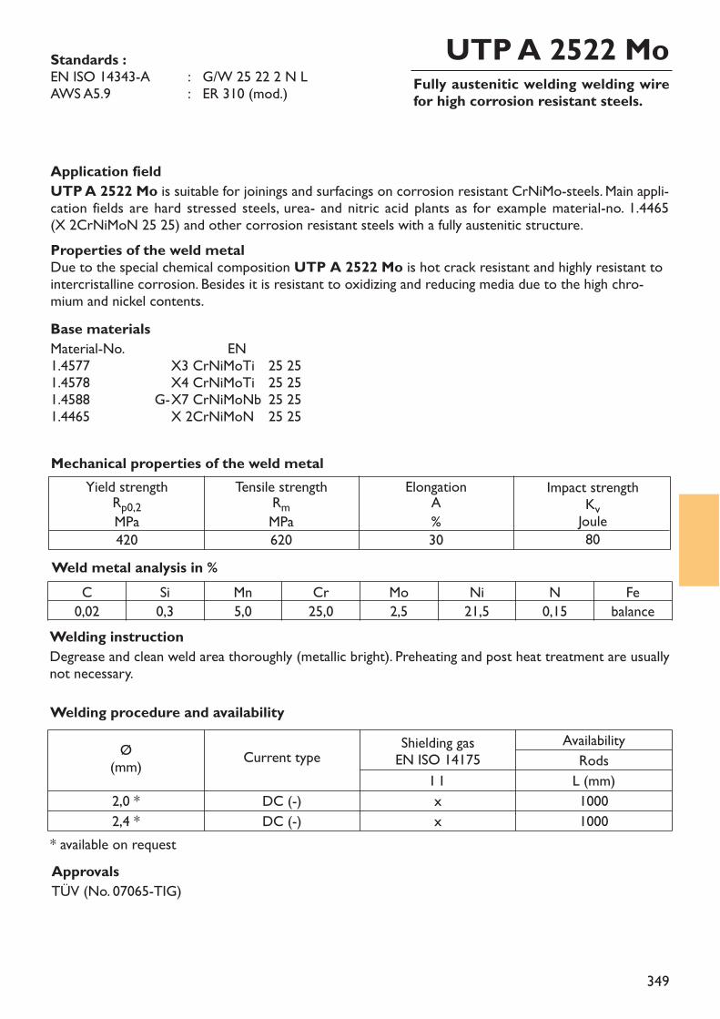
349
Fully austenitic welding welding wirefor high corrosion resistant steels.
UTP A 2522 MoStandards :EN ISO 14343-A : G/W 25 22 2 N LAWS A5.9 : ER 310 (mod.)
Application fieldUTP A 2522 Mo is suitable for joinings and surfacings on corrosion resistant CrNiMo-steels. Main appli-cation fields are hard stressed steels, urea- and nitric acid plants as for example material-no. 1.4465 (X 2CrNiMoN 25 25) and other corrosion resistant steels with a fully austenitic structure.Properties of the weld metalDue to the special chemical composition UTP A 2522 Mo is hot crack resistant and highly resistant tointercristalline corrosion. Besides it is resistant to oxidizing and reducing media due to the high chro-mium and nickel contents.Base materialsMaterial-No. EN1.4577 X3 CrNiMoTi 25 251.4578 X4 CrNiMoTi 25 251.4588 G-X7 CrNiMoNb 25 251.4465 X 2CrNiMoN 25 25
Weld metal analysis in %
Yield strengthRp0,2MPa420
Tensile strengthRmMPa620
ElongationA%30
Impact strengthKvJoule80
Mechanical properties of the weld metal
* available on request
C Si Mn Cr Mo Ni N Fe0,02 0,3 5,0 25,0 2,5 21,5 0,15 balance
ApprovalsTÜV (No. 07065-TIG)
Welding procedure and availability
Ø(mm) Current type Shielding gas
EN ISO 14175Availability
RodsI 1 L (mm)
2,0 * DC (-) x 10002,4 * DC (-) x 1000
Welding instructionDegrease and clean weld area thoroughly (metallic bright). Preheating and post heat treatment are usuallynot necessary.
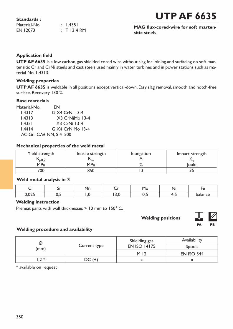
350
MAG flux-cored-wire for soft marten-sitic steels
UTP AF 6635Standards :Material-No. : 1.4351EN 12073 : T 13 4 RM
Application fieldUTP AF 6635 is a low carbon, gas shielded cored wire without slag for joining and surfacing on soft mar-tensitic Cr and CrNi steels and cast steels used mainly in water turbines and in power stations such as ma-terial No. 1.4313. Welding propertiesUTP AF 6635 is weldable in all positions except vertical-down. Easy slag removal, smooth and notch-freesurface. Recovery 130 %.Base materialsMaterial-No. EN1.4317 G X4 CrNi 13-41.4313 X3 CrNiMo 13-41.4351 X3 CrNi 13-41.4414 G X4 CrNiMo 13-4ACIGr. CA6 NM, S 41500
Weld metal analysis in %
Yield strengthRp0,2MPa700
Tensile strengthRmMPa850
ElongationA%13
Impact strengthKvJoule35
Mechanical properties of the weld metal
C Si Mn Cr Mo Ni Fe0,025 0,5 1,0 13,0 0,5 4,5 balance
Welding positionsWelding procedure and availability
* available on request
Ø(mm) Current type Shielding gas
EN ISO 14175AvailabilitySpools
M 12 EN ISO 5441,2 * DC (+) x x
Welding instructionPreheat parts with wall thicknesses > 10 mm to 150° C.
PA PB
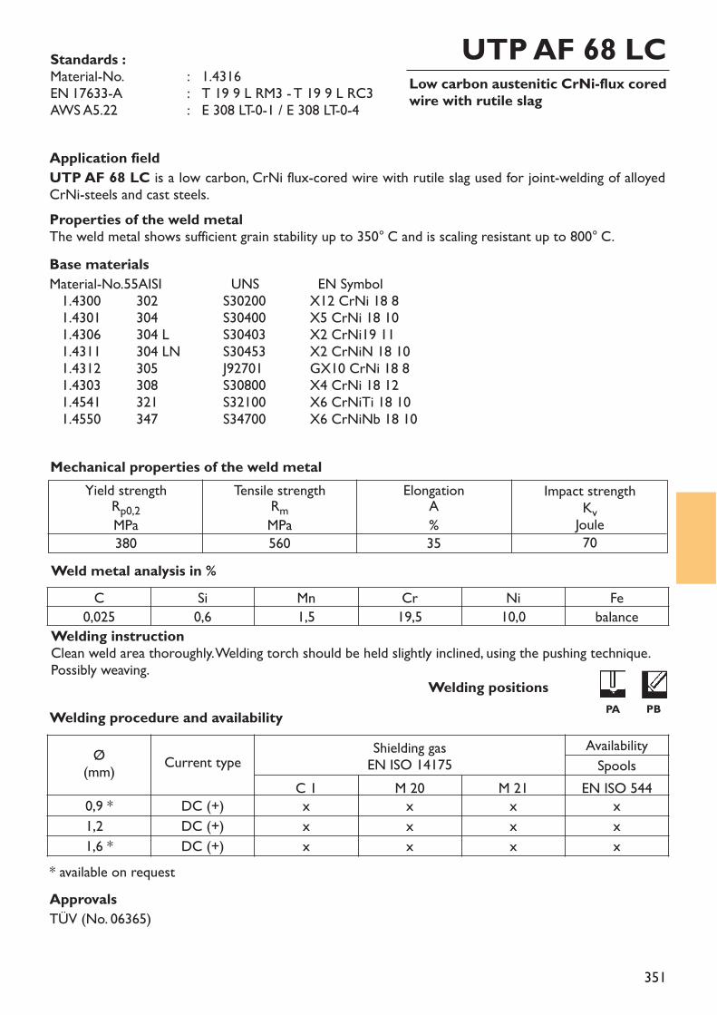
351
Low carbon austenitic CrNi-flux coredwire with rutile slag
UTP AF 68 LCStandards :Material-No. : 1.4316EN 17633-A : T 19 9 L RM3 - T 19 9 L RC3AWS A5.22 : E 308 LT-0-1 / E 308 LT-0-4
Welding instructionClean weld area thoroughly. Welding torch should be held slightly inclined, using the pushing technique.Possibly weaving.
Application fieldUTP AF 68 LC is a low carbon, CrNi flux-cored wire with rutile slag used for joint-welding of alloyed CrNi-steels and cast steels.Properties of the weld metalThe weld metal shows sufficient grain stability up to 350° C and is scaling resistant up to 800° C. Base materialsMaterial-No.55AISI UNS EN Symbol1.4300 302 S30200 X12 CrNi 18 81.4301 304 S30400 X5 CrNi 18 101.4306 304 L S30403 X2 CrNi19 111.4311 304 LN S30453 X2 CrNiN 18 101.4312 305 J92701 GX10 CrNi 18 81.4303 308 S30800 X4 CrNi 18 121.4541 321 S32100 X6 CrNiTi 18 101.4550 347 S34700 X6 CrNiNb 18 10
Weld metal analysis in %
Yield strengthRp0,2MPa380
Tensile strengthRmMPa560
ElongationA%35
Impact strengthKvJoule70
Mechanical properties of the weld metal
Welding procedure and availability
* available on request
C Si Mn Cr Ni Fe0,025 0,6 1,5 19,5 10,0 balance
Ø(mm) Current type Shielding gas
EN ISO 14175AvailabilitySpools
C 1 M 20 M 21 EN ISO 5440,9 * DC (+) x x x x1,2 DC (+) x x x x1,6 * DC (+) x x x x
Welding positions
ApprovalsTÜV (No. 06365)
PA PB
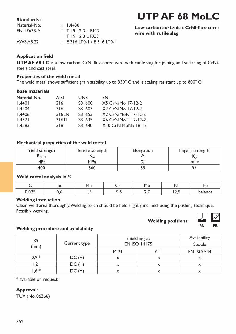
352
Low-carbon austenitic CrNi-flux-coreswire with rutile slag
UTP AF 68 MoLCStandards :Material-No. : 1.4430EN 17633-A : T 19 12 3 L RM3
T 19 12 3 L RC3AWS A5.22 : E 316 LT0-1 / E 316 LT0-4
Application fieldUTP AF 68 LC is a low carbon, CrNi flux-cored wire with rutile slag for joining and surfacing of CrNi-steels and cast steel.Properties of the weld metalThe weld metal shows sufficient grain stability up to 350° C and is scaling resistant up to 800° C. Base materialsMaterial-No. AISI UNS EN1.4401 316 S31600 X5 CrNiMo 17-12-21.4404 316L S31603 X2 CrNiMo 17-12-21.4406 316LN S31653 X2 CrNiMoN 17-12-21.4571 316Ti S31635 X6 CrNiMoTi 17-12-21.4583 318 S31640 X10 CrNiMoNb 18-12
Weld metal analysis in %
Yield strengthRp0,2MPa400
Tensile strengthRmMPa560
ElongationA%35
Impact strengthKvJoule55
Mechanical properties of the weld metal
C Si Mn Cr Mo Ni Fe0,025 0,6 1,5 19,5 2,7 12,5 balance
ApprovalsTÜV (No. 06366)
Welding instructionClean weld area thoroughly. Welding torch should be held slightly inclined, using the pushing technique.Possibly weaving.
Welding procedure and availability
* available on request
Ø(mm) Current type Shielding gas
EN ISO 14175AvailabilitySpools
M 21 C 1 EN ISO 5440,9 * DC (+) x x x1,2 DC (+) x x x1,6 * DC (+) x x x
PA PBWelding positions
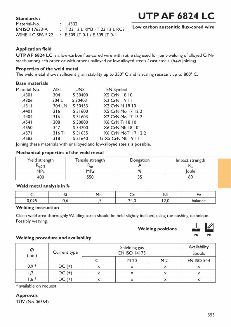
353
Low carbon austenitic flux-cored wireUTP AF 6824 LCStandards :
Material-No. : 1.4332EN ISO 17633-A : T 23 12 L RM3 - T 23 12 L RC3ASME II C SFA 5.22 : E 309 LT 0-1 / E 309 LT 0-4
Application fieldUTP AF 6824 LC is a low-carbon flux-cored wire with rutile slag used for joint-welding of alloyed CrNi-steels among ach other or with other unalloyed or low alloyed steels / cast steels. (b+w joining).Properties of the weld metalThe weld metal shows sufficient grain stability up to 350° C and is scaling resistant up to 800° C.Base materialsMaterial-No. AISI UNS EN Symbol1.4301 304 S 30400 X5 CrNi 18 101.4306 304 L S 30403 X2 CrNi 19 111.4311 304 LN S 30453 X2 CrNiN 18 101.4401 316 S 31600 X5 CrNiMo 17 12 21.4404 316 L S 31603 X2 CrNiMo 17 13 21.4541 308 S 30800 X6 CrNiTi 18 101.4550 347 S 34700 X6 CrNiNb 18 101.4571 316 Ti S 31635 X6 CrNiMoTi 17 12 21.4583 318 S 31640 G-X5 CrNiNb 19 11
Joining these materials with unalloyed and low-alloyed steels is possible.
Weld metal analysis in %
Yield strengthRp0,2MPa400
Tensile strengthRmMPa550
ElongationA%35
Impact strengthKvJoule60
Mechanical properties of the weld metal
C Si Mn Cr Ni Fe0,025 0,6 1,5 24,0 12,0 balance
Welding procedure and availability
* available on request
Ø(mm) Current type Shielding gas
EN ISO 14175AvailabilitySpools
C 1 M 20 M 21 EN ISO 5440,9 * DC (+) x x x x1,2 DC (+) x x x x1,6 * DC (+) x x x x
Welding positions
ApprovalsTÜV (No. 06364)
Welding instructionClean weld area thoroughly. Welding torch should be held slightly inclined, using the pushing technique.Possibly weaving.
PA PB
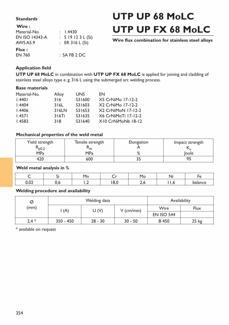
354
Application fieldUTP UP 68 MoLC in combination with UTP UP FX 68 MoLC is applied for joining and cladding ofstainless steel alloys type e. g. 316 L using the submerged arc welding process.Base materialsMaterial-No. Alloy UNS EN 1.4401 316 S31600 X5 CrNiMo 17-12-21.4404 316L S31603 X2 CrNiMo 17-12-21.4406 316LN S31653 X2 CrNiMoN 17-12-21.4571 316Ti S31635 X6 CrNiMoTi 17-12-21.4583 318 S31640 X10 CrNiMoNb 18-12
Weld metal analysis in %
Yield strengthRp0,2MPa420
Tensile strengthRmMPa600
ElongationA%35
Impact strengthKvJoule95
Mechanical properties of the weld metal
Standards Wire :Material-No. : 1.4430EN ISO 14343-A : S 19 12 3 L (Si)AWS A5.9 : ER 316 L (Si)Flux :EN 760 : SA FB 2 DC
Wire flux combination for stainless steel alloys
UTP UP 68 MoLCUTP UP FX 68 MoLC
C Si Mn Cr Mo Ni Fe0,02 0,6 1,2 18,0 2,6 11,6 balance
* available on request
Welding procedure and availabilityØ
(mm)Welding data Availability
I (A) U (V) V (cm/min) Wire FluxEN ISO 544
2,4 * 350 - 450 28 - 30 30 - 50 B 450 25 kg
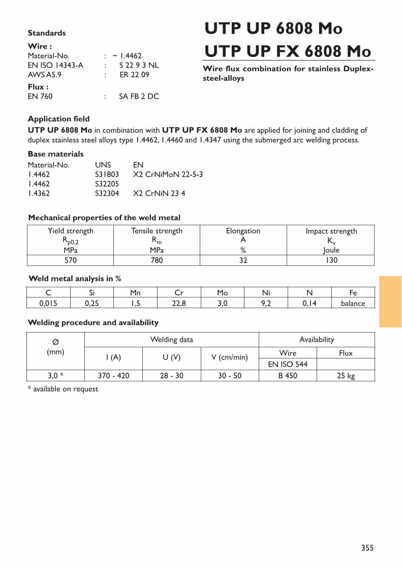
355
Application fieldUTP UP 6808 Mo in combination with UTP UP FX 6808 Mo are applied for joining and cladding ofduplex stainless steel alloys type 1.4462, 1.4460 and 1.4347 using the submerged arc welding process.Base materialsMaterial-No. UNS EN 1.4462 S31803 X2 CrNiMoN 22-5-31.4462 S322051.4362 S32304 X2 CrNiN 23 4
Weld metal analysis in %
Yield strengthRp0,2MPa570
Tensile strengthRmMPa780
ElongationA%32
Impact strengthKvJoule130
Mechanical properties of the weld metal
Standards Wire :Material-No. : ~ 1.4462EN ISO 14343-A : S 22 9 3 NLAWS A5.9 : ~ ER 22 09Flux :EN 760 : ~ SA FB 2 DC
Wire flux combination for stainless Duplex-steel-alloys
UTP UP 6808 MoUTP UP FX 6808 Mo
* available on request
C Si Mn Cr Mo Ni N Fe0,015 0,25 1,5 22,8 3,0 9,2 0,14 balance
Welding procedure and availabilityØ
(mm)Welding data Availability
I (A) U (V) V (cm/min) Wire FluxEN ISO 544
3,0 * 370 - 420 28 - 30 30 - 50 B 450 25 kg
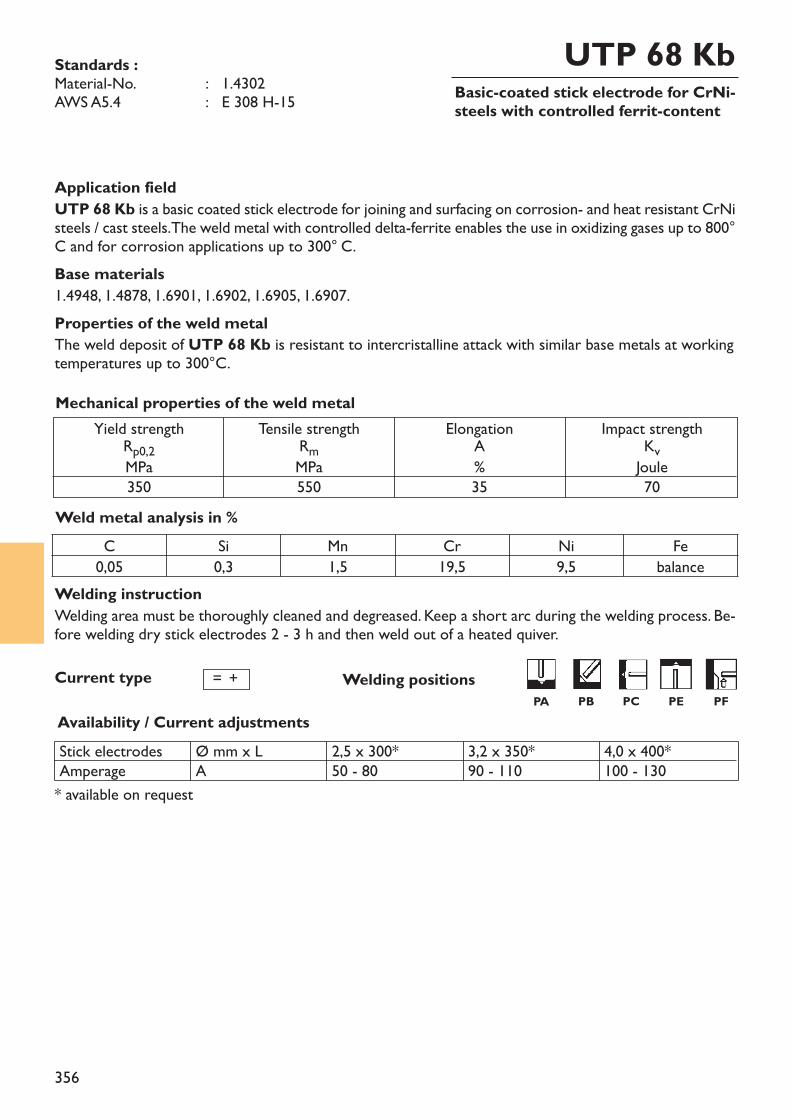
356
Basic-coated stick electrode for CrNi-steels with controlled ferrit-content
UTP 68 KbStandards :Material-No. : 1.4302AWS A5.4 : E 308 H-15
Welding instructionWelding area must be thoroughly cleaned and degreased. Keep a short arc during the welding process. Be-fore welding dry stick electrodes 2 - 3 h and then weld out of a heated quiver.
Application fieldUTP 68 Kb is a basic coated stick electrode for joining and surfacing on corrosion- and heat resistant CrNisteels / cast steels. The weld metal with controlled delta-ferrite enables the use in oxidizing gases up to 800°C and for corrosion applications up to 300° C.Base materials1.4948, 1.4878, 1.6901, 1.6902, 1.6905, 1.6907.Properties of the weld metalThe weld deposit of UTP 68 Kb is resistant to intercristalline attack with similar base metals at workingtemperatures up to 300°C.
Weld metal analysis in %
Yield strengthRp0,2MPa350
Tensile strengthRmMPa550
ElongationA%35
Impact strengthKvJoule70
Mechanical properties of the weld metal
Current type
Availability / Current adjustments
= +
Stick electrodesAmperage
Ø mm x LA
2,5 x 300*50 - 80
3,2 x 350*90 - 110
4,0 x 400*100 - 130
* available on request
Welding positions
C Si Mn Cr Ni Fe0,05 0,3 1,5 19,5 9,5 balance
PA PB PC PE PF
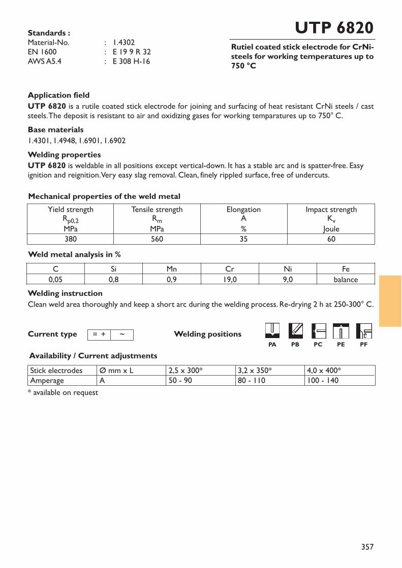
357
Rutiel coated stick electrode for CrNi-steels for working temperatures up to750 °C
UTP 6820Standards :Material-No. : 1.4302EN 1600 : E 19 9 R 32AWS A5.4 : E 308 H-16
Welding instructionClean weld area thoroughly and keep a short arc during the welding process. Re-drying 2 h at 250-300° C.
Application fieldUTP 6820 is a rutile coated stick electrode for joining and surfacing of heat resistant CrNi steels / caststeels. The deposit is resistant to air and oxidizing gases for working temparatures up to 750° C.Base materials1.4301, 1.4948, 1.6901, 1.6902Welding propertiesUTP 6820 is weldable in all positions except vertical-down. It has a stable arc and is spatter-free. Easyignition and reignition. Very easy slag removal. Clean, finely rippled surface, free of undercuts.
Weld metal analysis in %
Yield strengthRp0,2MPa380
Tensile strengthRmMPa560
ElongationA%35
Impact strengthKvJoule60
Mechanical properties of the weld metal
Availability / Current adjustmentsStick electrodesAmperage
Ø mm x LA
2,5 x 300*50 - 90
3,2 x 350*80 - 110
4,0 x 400*100 - 140
* available on request
Welding positions
C Si Mn Cr Ni Fe0,05 0,8 0,9 19,0 9,0 balance
Current type = + ~PA PB PC PE PF
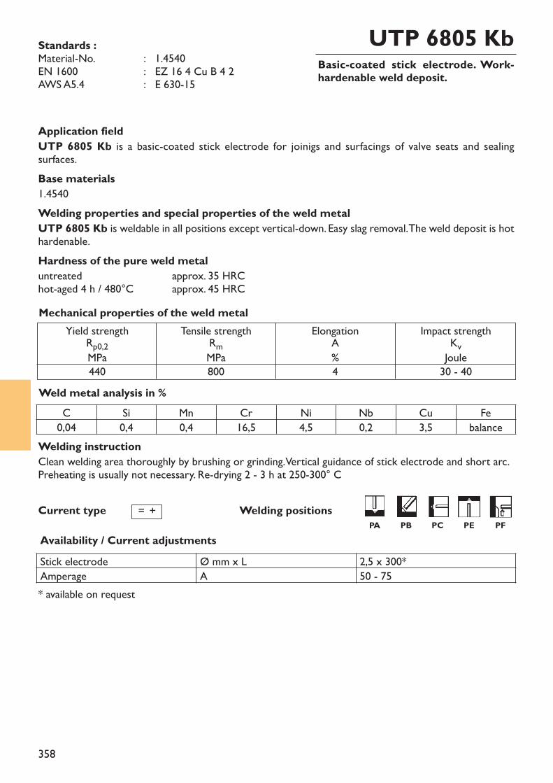
358
Basic-coated stick electrode. Work-hardenable weld deposit.
UTP 6805 KbStandards :Material-No. : 1.4540EN 1600 : EZ 16 4 Cu B 4 2AWS A5.4 : E 630-15
Welding instructionClean welding area thoroughly by brushing or grinding. Vertical guidance of stick electrode and short arc.Preheating is usually not necessary. Re-drying 2 - 3 h at 250-300° C
Application fieldUTP 6805 Kb is a basic-coated stick electrode for joinigs and surfacings of valve seats and sealing surfaces.Base materials1.4540Welding properties and special properties of the weld metalUTP 6805 Kb is weldable in all positions except vertical-down. Easy slag removal. The weld deposit is hothardenable.Hardness of the pure weld metaluntreated approx. 35 HRChot-aged 4 h / 480°C approx. 45 HRC
Weld metal analysis in %
Yield strengthRp0,2MPa440
Tensile strengthRmMPa800
ElongationA%4
Impact strengthKvJoule30 - 40
Mechanical properties of the weld metal
Availability / Current adjustments
* available on request
Welding positionsCurrent type = +
C Si Mn Cr Ni Nb Cu Fe0,04 0,4 0,4 16,5 4,5 0,2 3,5 balance
Stick electrode Ø mm x L 2,5 x 300*Amperage A 50 - 75
PA PB PC PE PF
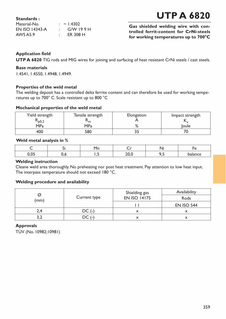
359
Gas shielded welding wire with con-trolled ferrit-content for CrNi-steelsfor working temperatures up to 700°C
UTP A 6820Standards :Material-No. : ~ 1.4302EN ISO 14343-A : ~ G/W 19 9 H AWS A5.9 : ~ ER 308 H
Welding instructionCleane weld area thoroughly. No preheating nor post heat treatment. Pay attention to low heat input.The interpass temperature should not exceed 180 °C.
Application fieldUTP A 6820 TIG rods and MIG wires for joining and surfacing of heat resistant CrNi steels / cast steels. Base materials1.4541, 1.4550, 1.4948, 1.4949.
Properties of the weld metalThe welding deposit has a controlled delta ferrite content and can therefore be used for working tempe-ratures up to 700° C. Scale resistant up to 800 °C
Weld metal analysis in %
Yield strengthRp0,2MPa400
Tensile strengthRmMPa580
ElongationA%35
Impact strengthKvJoule70
Mechanical properties of the weld metal
C Si Mn Cr Ni Fe0,05 0,6 1,5 20,0 9,5 balance
Welding procedure and availability
Ø(mm) Current type Shielding gas
EN ISO 14175Availability
RodsI 1 EN ISO 544
2,4 DC (-) x x3,2 DC (-) x x
ApprovalsTÜV (No. 10982;10981)
360
Index
Welding consumables for low-alloyed steels
stick electrodessolid rods and wires
Group 7Welding consumablesfor low-alloyed steels
361
Welding consumables for low-alloyed steelsstick electrodessolid rods and wires
364 – 371372 – 375
pagexxx
Group 7Welding consumablesfor low-alloyed steels
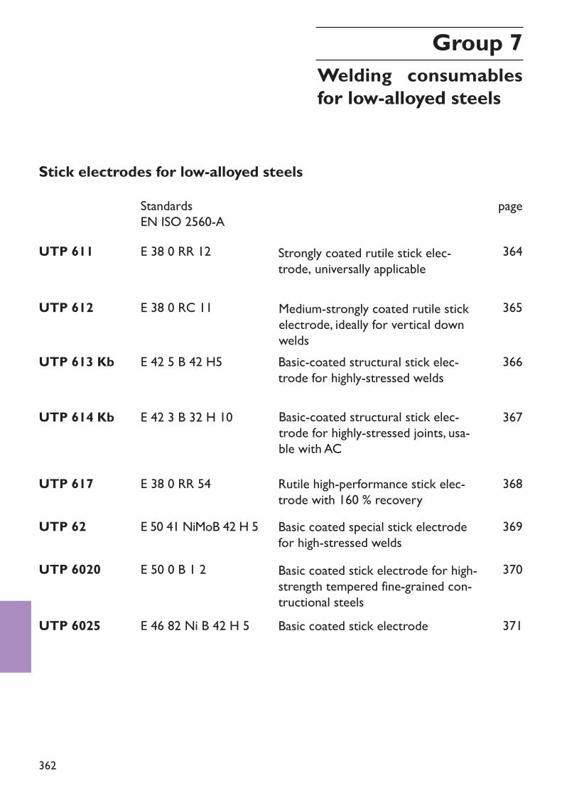
362
Stick electrodes for low-alloyed steelsStandardsEN ISO 2560-A
UTP 62 E 50 41 NiMoB 42 H 5
page
369
UTP 6020 E 50 0 B 1 2 370
UTP 6025 E 46 82 Ni B 42 H 5 371
UTP 611 E 38 0 RR 12
UTP 612 E 38 0 RC 11
UTP 613 Kb E 42 5 B 42 H5
364
365
366
UTP 614 Kb E 42 3 B 32 H 10 367
UTP 617 E 38 0 RR 54 368
Group 7Welding consumablesfor low-alloyed steels
Basic coated special stick electrodefor high-stressed weldsBasic coated stick electrode for high-strength tempered fine-grained con-tructional steelsBasic coated stick electrode
Strongly coated rutile stick elec-trode, universally applicable
Medium-strongly coated rutile stickelectrode, ideally for vertical downweldsBasic-coated structural stick elec-trode for highly-stressed welds
Basic-coated structural stick elec-trode for highly-stressed joints, usa-ble with AC
Rutile high-performance stick elec-trode with 160 % recovery
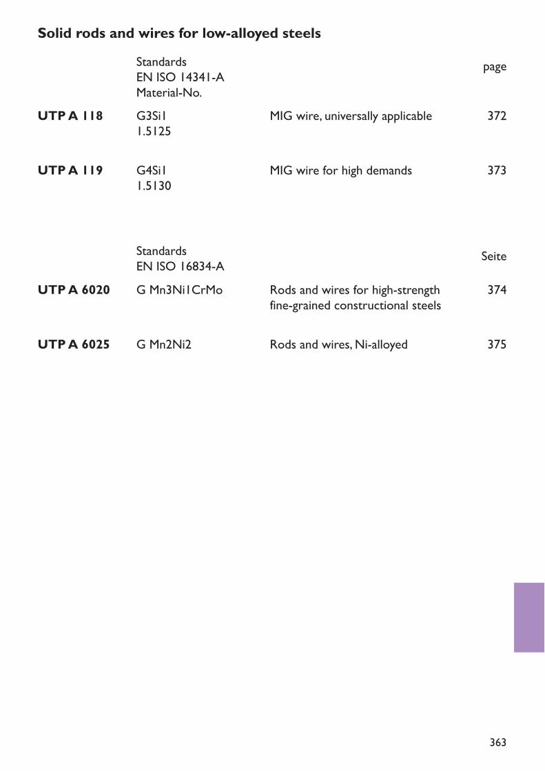
363
Solid rods and wires for low-alloyed steelsStandardsEN ISO 14341-AMaterial-No.
page
StandardsEN ISO 16834-A Seite
UTP A 118 G3Si11.5125
UTP A 119 G4Si11.5130
372
373
UTP A 6020 G Mn3Ni1CrMo
UTP A 6025 G Mn2Ni2
374
375
MIG wire for high demands
MIG wire, universally applicable
Rods and wires, Ni-alloyed
Rods and wires for high-strengthfine-grained constructional steels
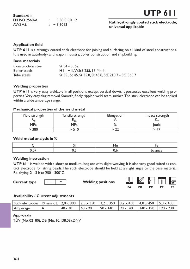
364
Rutile, strongly coated stick electrode,universal applicable
UTP 611
Welding instructionUTP 611 is welded with a short to medium-long arc with slight weaving. It is also very good suited as con-tact electrode for string beads. The stick electrode should be held at a slight angle to the base material. Re-drying: 2 - 3 h at 250 - 300°C.
ApprovalsTÜV (No. 02180), DB (No. 10.138.08),DNV
Welding positions
Standard :EN ISO 2560-A : ~ E 38 0 RR 12AWS A5.1 : ~ E 6013
Application fieldUTP 611 is a strongly coated stick electrode for joining and surfacing on all kind of steel constructions.It is used in autobody- and wagon industry, boiler construction and shipbuilding.Base materialsConstruction steel St 34 - St 52Boiler steels H I - H II, WStE 255, 17 Mn 4Tube steels St 35 , St 45, St 35.8, St 45.8, StE 210.7 - StE 360.7
Welding propertiesUTP 611 is very easy weldable in all positions except vertical down. It possesses excellent welding pro-perties. Very easy slag removal. Smooth, finely rippled weld seam surface. The stick electrode can be appliedwithin a wide amperage range.
Weld metal analysis in %
Availability / Current adjustments
Yield strengthReMPa> 380
Tensile strengthRmMPa> 510
ElongationA%> 22
Impact strengthKvJoule> 47
Mechanical properties of the weld metal
C Si Mn Fe0,07 0,5 0,6 balance
Current type = - ~
Stick electrodes Ø mm x L 2,0 x 300 2,5 x 350 3,2 x 350 3,2 x 450 4,0 x 450 5,0 x 450Amperage A 40 - 70 60 - 90 90 - 140 90 - 140 140 - 190 190 - 230
PA PB PC PE PF
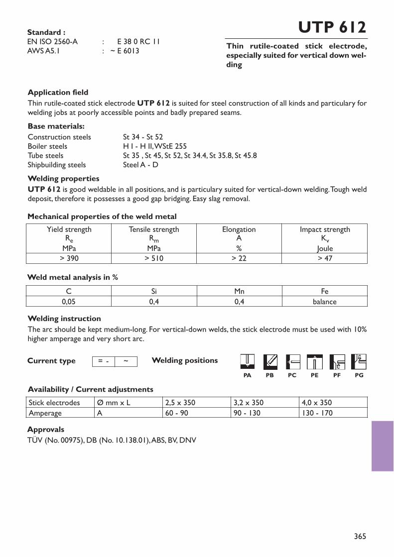
365
Thin rutile-coated stick electrode,especially suited for vertical down wel-ding
UTP 612
Welding instructionThe arc should be kept medium-long. For vertical-down welds, the stick electrode must be used with 10%higher amperage and very short arc.
ApprovalsTÜV (No. 00975), DB (No. 10.138.01), ABS, BV, DNV
Welding positions
Standard :EN ISO 2560-A : ~ E 38 0 RC 11AWS A5.1 : ~ E 6013
Application fieldThin rutile-coated stick electrode UTP 612 is suited for steel construction of all kinds and particulary forwelding jobs at poorly accessible points and badly prepared seams.Base materials:Construction steels St 34 - St 52Boiler steels H I - H II, WStE 255Tube steels St 35 , St 45, St 52, St 34.4, St 35.8, St 45.8Shipbuilding steels Steel A - DWelding propertiesUTP 612 is good weldable in all positions, and is particulary suited for vertical-down welding. Tough welddeposit, therefore it possesses a good gap bridging. Easy slag removal.
Weld metal analysis in %
Availability / Current adjustments
Yield strengthReMPa> 390
Tensile strengthRmMPa> 510
ElongationA%> 22
Impact strengthKvJoule> 47
Mechanical properties of the weld metal
C Si Mn Fe0,05 0,4 0,4 balance
Current type = - ~PG
Stick electrodes Ø mm x L 2,5 x 350 3,2 x 350 4,0 x 350Amperage A 60 - 90 90 - 130 130 - 170
PA PB PC PE PF
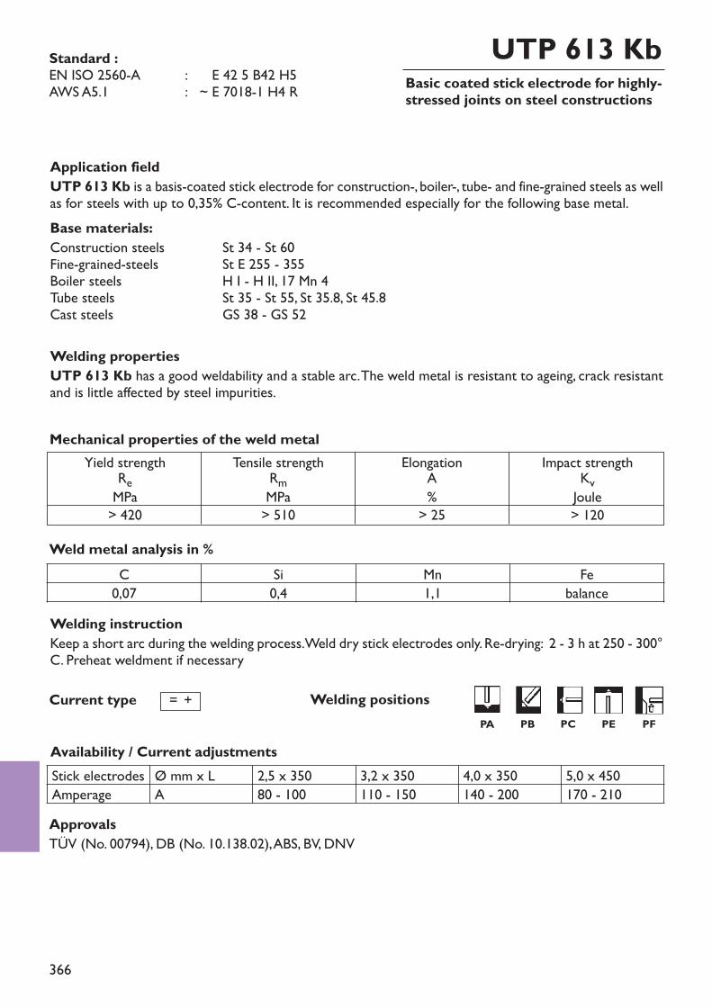
366
Basic coated stick electrode for highly-stressed joints on steel constructions
UTP 613 Kb
Welding instructionKeep a short arc during the welding process. Weld dry stick electrodes only. Re-drying: 2 - 3 h at 250 - 300°C. Preheat weldment if necessary
ApprovalsTÜV (No. 00794), DB (No. 10.138.02), ABS, BV, DNV
Welding positions
Standard :EN ISO 2560-A : ~ E 42 5 B42 H5AWS A5.1 : ~ E 7018-1 H4 R
Application fieldUTP 613 Kb is a basis-coated stick electrode for construction-, boiler-, tube- and fine-grained steels as wellas for steels with up to 0,35% C-content. It is recommended especially for the following base metal.Base materials:Construction steels St 34 - St 60Fine-grained-steels St E 255 - 355Boiler steels H I - H II, 17 Mn 4Tube steels St 35 - St 55, St 35.8, St 45.8Cast steels GS 38 - GS 52
Welding propertiesUTP 613 Kb has a good weldability and a stable arc. The weld metal is resistant to ageing, crack resistantand is little affected by steel impurities.
Weld metal analysis in %
Availability / Current adjustments
Yield strengthReMPa> 420
Tensile strengthRmMPa> 510
ElongationA%> 25
Impact strengthKvJoule> 120
Mechanical properties of the weld metal
C Si Mn Fe0,07 0,4 1,1 balance
Stick electrodes Ø mm x L 2,5 x 350 3,2 x 350 4,0 x 350 5,0 x 450Amperage A 80 - 100 110 - 150 140 - 200 170 - 210
Current type = +PA PB PC PE PF
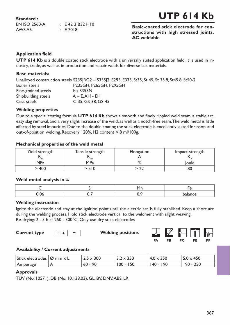
367
Basic-coated stick electrode for con-structions with high stressed joints,AC-weldable
UTP 614 Kb
Welding instructionIgnite the electrode and stay at the ignition point until the electric arc is fully stabilised. Keep a short arcduring the welding process. Hold stick electrode vertical to the weldment with slight weaving. Re-drying: 2 - 3 h at 250 - 300°C. Only use dry stick electrodes
ApprovalsTÜV (No. 10571), DB (No. 10.138.03), GL, BV, DNV, ABS, LR
Welding positions
Standard :EN ISO 2560-A : E 42 3 B32 H10AWS A5.1 : E 7018
Application fieldUTP 614 Kb is a double coated stick electrode with a universally suited application field. It is used in in-dustry, trade, as well as in production and repair welds for diverse bas materials.Base materials:Unalloyed construction steels S235JRG2 – S355J2; E295, E335, St35, St 45, St 35.8, St45.8, St50-2Boiler steels P235GH, P265GH, P295GHFine-grained steels bis S355NShipbuilding steels A – E, AH - EHCast steels C 35, GS-38, GS-45Welding propertiesDue to a special coating formula UTP 614 Kb shows a smooth and finely rippled weld seam, a stable arc,easy slag removal, and a very slight increase of the weld, as well as a notch-free seam. The weld metal is littleaffected by steel impurities. Due to the double coating the stick electrode is excellently suited for root- andout-of-position welding. Recovery 120%, H2 content < 8 ml/100g.
Weld metal analysis in %
Availability / Current adjustments
Yield strengthReMPa> 400
Tensile strengthRmMPa> 510
ElongationA%> 22
Impact strengthKvJoule80
Mechanical properties of the weld metal
C Si Mn Fe0,06 0,7 0,9 balance
Current type = + ~
Stick electrodes Ø mm x L 2,5 x 300 3,2 x 350 4,0 x 350 5,0 x 450Amperage A 60 - 90 100 - 150 140 - 190 190 - 250
PA PB PC PE PF
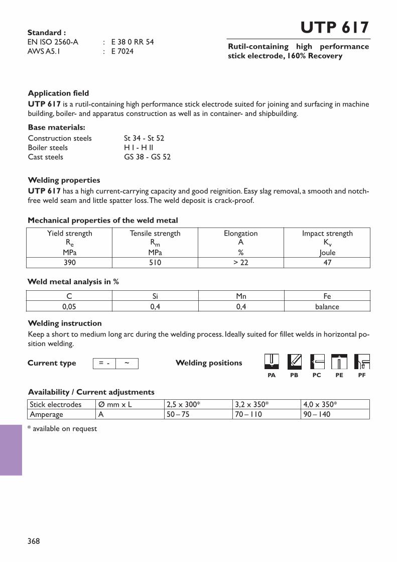
368
Rutil-containing high performancestick electrode, 160% Recovery
UTP 617
Welding instructionKeep a short to medium long arc during the welding process. Ideally suited for fillet welds in horizontal po-sition welding.
Welding positions
Standard :EN ISO 2560-A : E 38 0 RR 54AWS A5.1 : E 7024
Application fieldUTP 617 is a rutil-containing high performance stick electrode suited for joining and surfacing in machinebuilding, boiler- and apparatus construction as well as in container- and shipbuilding.Base materials:Construction steels St 34 - St 52Boiler steels H I - H IICast steels GS 38 - GS 52
Welding propertiesUTP 617 has a high current-carrying capacity and good reignition. Easy slag removal, a smooth and notch-free weld seam and little spatter loss. The weld deposit is crack-proof.
Weld metal analysis in %
Availability / Current adjustmentsStick electrodesAmperage
Ø mm x LA
2,5 x 300*50 – 75
3,2 x 350*70 – 110
4,0 x 350*90 – 140
Yield strengthReMPa390
Tensile strengthRmMPa510
ElongationA%> 22
Impact strengthKvJoule47
Mechanical properties of the weld metal
C Si Mn Fe0,05 0,4 0,4 balance
Current type = - ~
* available on request
PA PB PC PE PF
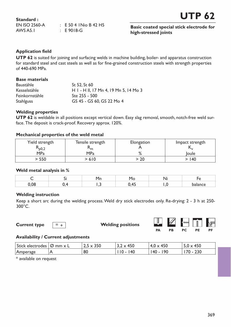
369
Basic coated special stick electrode forhigh-stressed joints
UTP 62Standard :EN ISO 2560-A : E 50 4 1Nio B 42 H5AWS A5.1 : E 9018-G
Welding instructionKeep a short arc during the welding process. Weld dry stick electrodes only. Re-drying: 2 - 3 h at 250-300°C.
Welding positions
Application fieldUTP 62 is suited for joining and surfacing welds in machine building, boiler- and apparatus constructionfor standard steel and cast steels as well as for fine-grained construction steels with strength propertiesof 440-690 MPa.Base materialsBaustähle St 52, St 60Kesselstähle H 1 - H II, 17 Mn 4, 19 Mn 5, 14 Mo 3Feinkornstähle Ste 255 - 500Stahlguss GS 45 - GS 60, GS 22 Mo 4Welding propertiesUTP 62 is weldable in all positions except vertical down. Easy slag removal, smooth, notch-free weld sur-face. The deposit is crack-proof. Recovery approx. 120%.
Weld metal analysis in %
Availability / Current adjustments
Yield strengthRp0,2MPa> 550
Tensile strengthRmMPa> 610
ElongationA%> 20
Impact strengthKvJoule> 140
Mechanical properties of the weld metal
Current type = +
* available on request
C Si Mn Mo Ni Fe0,08 0,4 1,3 0,45 1,0 balance
Stick electrodes Ø mm x L 2,5 x 350 3,2 x 450 4,0 x 450 5,0 x 450Amperage A 80 110 - 140 140 - 190 170 - 230
PA PB PC PE PF
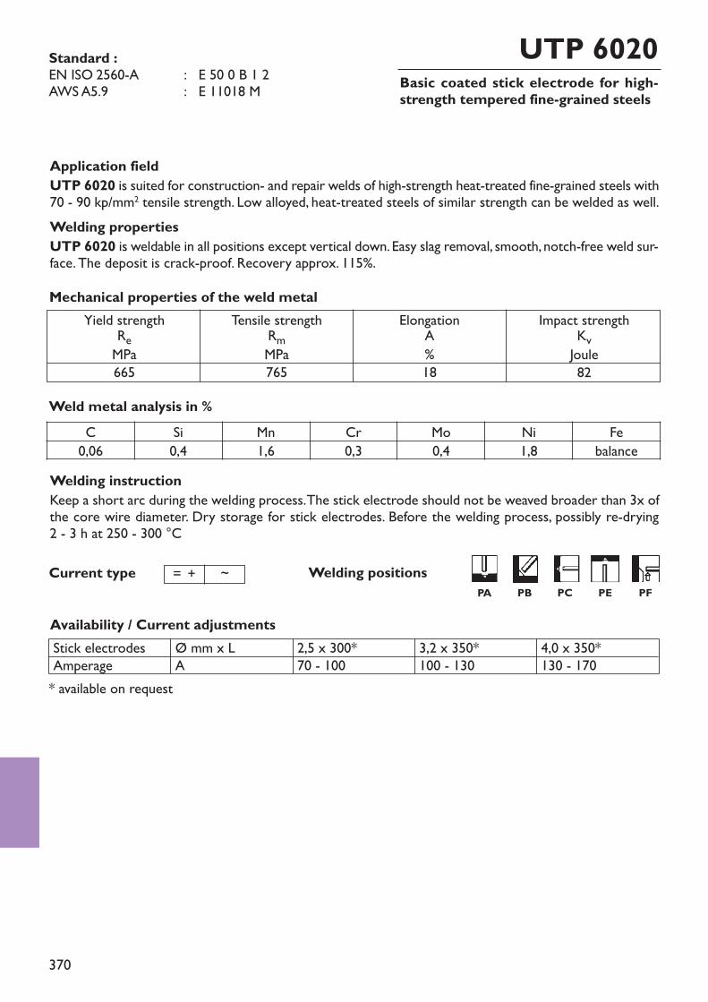
370
Basic coated stick electrode for high-strength tempered fine-grained steels
UTP 6020
Welding instructionKeep a short arc during the welding process. The stick electrode should not be weaved broader than 3x ofthe core wire diameter. Dry storage for stick electrodes. Before the welding process, possibly re-drying 2 - 3 h at 250 - 300 °C
Welding positions
Standard :EN ISO 2560-A : E 50 0 B 1 2AWS A5.9 : E 11018 M
Application fieldUTP 6020 is suited for construction- and repair welds of high-strength heat-treated fine-grained steels with70 - 90 kp/mm2 tensile strength. Low alloyed, heat-treated steels of similar strength can be welded as well.Welding propertiesUTP 6020 is weldable in all positions except vertical down. Easy slag removal, smooth, notch-free weld sur-face. The deposit is crack-proof. Recovery approx. 115%.
Weld metal analysis in %
Availability / Current adjustments
Yield strengthReMPa665
Tensile strengthRmMPa765
ElongationA%18
Impact strengthKvJoule82
Mechanical properties of the weld metal
Current type = + ~
C Si Mn Cr Mo Ni Fe0,06 0,4 1,6 0,3 0,4 1,8 balance
* available on request
Stick electrodesAmperage
Ø mm x LA
2,5 x 300*70 - 100
3,2 x 350*100 - 130
4,0 x 350*130 - 170
PA PB PC PE PF

371
Basic coated stick electrodeUTP 6025
Welding instructionKeep a short arc during the welding process. The stick electrode should not be weaved broader than 3x ofthe core wire diameter. Dry storage for stick electrodes. Before the welding process, possibly re-drying 2 - 3 h at 250 - 300 °C
Welding positions
Standard :EN ISO 2560-A : E 46 82 Ni B42 H5
Application fieldUTP 6025 is a basic-coated stick electrode and is suited for joining and surfacing welds in the chemicalapparatus construction and for tube construction up to working temperatures of -100°C untreated and to -140°C hardened.Base materialsTT St 35 N - TT St 45 N, TT St 35 V - TT St 45 V, 14 Ni 6, 10 Ni 14, 12 Ni, 16 Ni 14, St-W-TT, St E 26-51Welding propertiesUTP 6025 is weldable in all positions except vertical down. Easy slag removal, smooth, notch-free weld sur-face. The weld deposit is cold-tough and crack-proof.
Weld metal analysis in %
Availability / Current adjustments
Yield strengthReMPa460
Tensile strengthRmMPa540
ElongationA%24
Impact strengthKvJoule110
Mechanical properties of the weld metal
Current type = +
* available on request
C Si Mn Ni Fe0,05 0,3 1,0 2,6 balance
Stick electrodes Ø mm x L 3,2 x 350* 4,0 x 450*Amperage A 110 - 140 140 - 180
PA PB PC PE PF
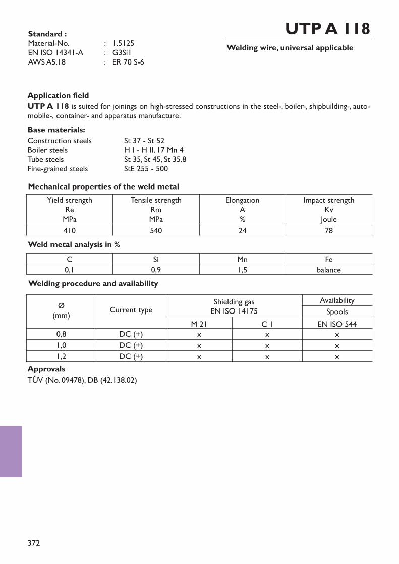
372
Standard :Material-No. : 1.5125EN ISO 14341-A : G3Si1AWS A5.18 : ER 70 S-6
Application fieldUTP A 118 is suited for joinings on high-stressed constructions in the steel-, boiler-, shipbuilding-, auto-mobile-, container- and apparatus manufacture.Base materials:Construction steels St 37 - St 52Boiler steels H I - H II, 17 Mn 4Tube steels St 35, St 45, St 35.8Fine-grained steels StE 255 - 500
Welding wire, universal applicableUTP A 118
Weld metal analysis in %
Mechanical properties of the weld metal
ApprovalsTÜV (No. 09478), DB (42.138.02)
C Si Mn Fe0,1 0,9 1,5 balance
Yield strengthReMPa
Tensile strengthRmMPa
ElongationA%
Impact strengthKvJoule
410 540 24 78
Welding procedure and availabilityØ(mm) Current type Shielding gas
EN ISO 14175AvailabilitySpools
M 21 C 1 EN ISO 5440,8 DC (+) x x x1,0 DC (+) x x x1,2 DC (+) x x x
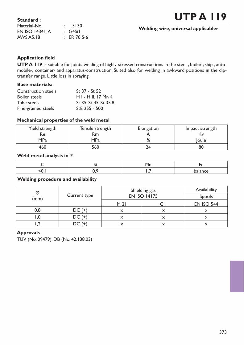
373
Standard :Material-No. : 1.5130EN ISO 14341-A : G4Si1AWS A5.18 : ER 70 S-6
Application fieldUTP A 119 is suitable for joints welding of highly-stressed constructions in the steel-, boiler-, ship-, auto-mobile-, container- and apparatus-construction. Suited also for welding in awkward positions in the dip-transfer range. Little loss in spraying.Base materials:Construction steels St 37 - St 52Boiler steels H I - H II, 17 Mn 4Tube steels St 35, St 45, St 35.8Fine-grained steels StE 255 - 500
Welding wire, universal applicablerUTP A 119
Weld metal analysis in %
Mechanical properties of the weld metal
ApprovalsTÜV (No. 09479), DB (No. 42.138.03)
C Si Mn Fe<0,1 0,9 1,7 balance
Yield strengthReMPa
Tensile strengthRmMPa
ElongationA%
Impact strengthKvJoule
460 560 24 80
Welding procedure and availabilityØ(mm) Current type Shielding gas
EN ISO 14175AvailabilitySpools
M 21 C 1 EN ISO 5440,8 DC (+) x x x1,0 DC (+) x x x1,2 DC (+) x x x
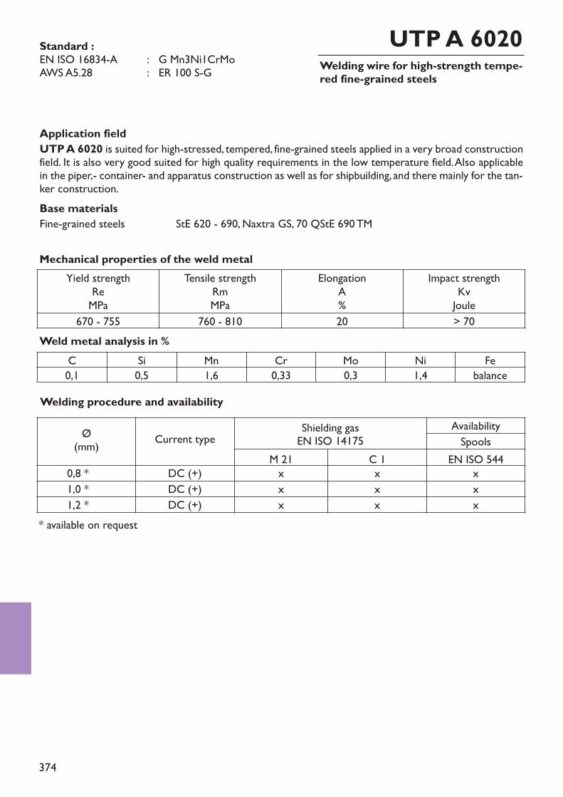
374
Standard :EN ISO 16834-A : G Mn3Ni1CrMoAWS A5.28 : ER 100 S-G
Application fieldUTP A 6020 is suited for high-stressed, tempered, fine-grained steels applied in a very broad constructionfield. It is also very good suited for high quality requirements in the low temperature field. Also applicablein the piper,- container- and apparatus construction as well as for shipbuilding, and there mainly for the tan-ker construction.Base materialsFine-grained steels StE 620 - 690, Naxtra GS, 70 QStE 690 TM
Welding wire for high-strength tempe-red fine-grained steels
UTP A 6020
Weld metal analysis in %
Mechanical properties of the weld metalYield strength
ReMPa
Tensile strengthRmMPa
ElongationA%
Impact strengthKvJoule
670 - 755 760 - 810 20 > 70
C Si Mn Cr Mo Ni Fe0,1 0,5 1,6 0,33 0,3 1,4 balance
* available on request
Welding procedure and availabilityØ(mm) Current type Shielding gas
EN ISO 14175AvailabilitySpools
M 21 C 1 EN ISO 5440,8 * DC (+) x x x1,0 * DC (+) x x x1,2 * DC (+) x x x
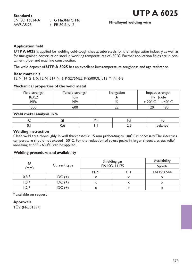
375
Standard :EN ISO 16834-A : G Mn3Ni1CrMoAWS A5.28 : ER 80 S-Ni 2
Application fieldUTP A 6025 is applied for welding cold-tough sheets, tube steels for the refrigeration industry as well asfor fine-grained construction steel in working temperatures of -80°C. Further application fields are in con-tainer-, pipe- and machine construction.The weld deposit of UTP A 6025 has an excellent low-temperature toughness and age resistance.Base materials12 Ni 14 G 1, X 12 Ni 514 Ni 6, P-S275NL2, P-S500QL1, 13 MnNi 6-3
Ni-alloyed welding wireUTP A 6025
Weld metal analysis in %
Mechanical properties of the weld metalYield strength
Rp0,2MPa
Tensile strengthRmMPa
ElongationA%
Impact strengthKv Joule
+ 20° C - 40° C500 600 22 120 80
C Si Mn Ni Fe0,1 0,6 1,1 2,5 balance
Welding instructionClean weld area thoroughly. In wall thicknesses > 15 mm preheating to 100°C is necessary. The interpasstemperature should not exceed 150°C. For the reduction of stress peaks in larger sheets a stress reliefannealing at 550 - 630°C can be applied.
ApprovalsTÜV (No. 01337)
* available on request
Welding procedure and availabilityØ(mm) Current type Shielding gas
EN ISO 14175AvailabilitySpools
M 21 C 1 EN ISO 5440,8 * DC (+) x x x1,0 * DC (+) x x x1,2 * DC (+) x x x
376
377
Index
UTP EXOBOND flame spraying powdersUTP UNIBOND flame spraying powdersUTP HABOND flame spraying powdersUTP PTA metal powders
More UTP flame spray powders are available namely • UTP METOXID powders• UTP TOPGUN powders• UTP PLAST / PLAST SUPER plastic flame spray powders
Group 8Flame spraying powders
378
Flame spraying powdersUTP EXOBONDUTP UNIBONDUTP HABONDUTP PTA
383 – 386387 – 389390 – 394395 – 396
page xxx
Group 8Flame spraying powders
379
UTP EXOBOND flame spraying powders
UTP EB–2001
page
384UTP EB–2002 384UTP EB–2003 385
UTP EB–1001UTP EB–1002 NUTP EB–1003
383383
UTP EB–2005UTP EB–2007
385385
UTP EB–3010 385UTP EB–4010 386UTP EB–5044 386
UTP EB–1050 384
383UTP EB–1025 384UTP EB–1030 384
Group 8Flame spraying powders
380
UTP UNIBOND flame spraying powders
UTP UB 5–2525 Apage387
UTP UB 5–2550 388UTP UB 5–2555 388
UTP UB 5–2540
UTP UB 5–2760UTP UB 5–2862
387
388388
UTP UB 5–2756 X4 389UTP UB 5–2864 389UTP UB 5–2864 4 389UTP UB 5–2871 389
UTP HA-BOND flame spraying powders
UTP HA–6315 G
page
390UTP HA–032 390
UTP HA–3 390UTP HA–6320 391UTP HA–2 391UTP HA–5 392UTP HA–06 393
381
UTP PTA metal powders
UTP PTA 2–708.11
page
395UTP PTA 2–712.10 395UTP PTA 2–712.11 395
UTP PTA 2–701.10UTP PTA 2–701.11UTP PTA 2–706.10
395395395
UTP PTA 2–706.11 395UTP PTA 2–708.10 395
UTP PTA 5–776.11 396
UTP PTA 3–710.10UTP PTA 3–710.11UTP PTA 5–068HH.10
396396
UTP PTA 2–721.10UTP PTA 2–721.11
396396
396UTP PTA 5–068HH.11 396UTP PTA 5–776.10 396
UTP HA–7UTP HA–8UTP HA–8 SS
393393394
UTP HA–6 393page
UTP HA–8–65 394

382
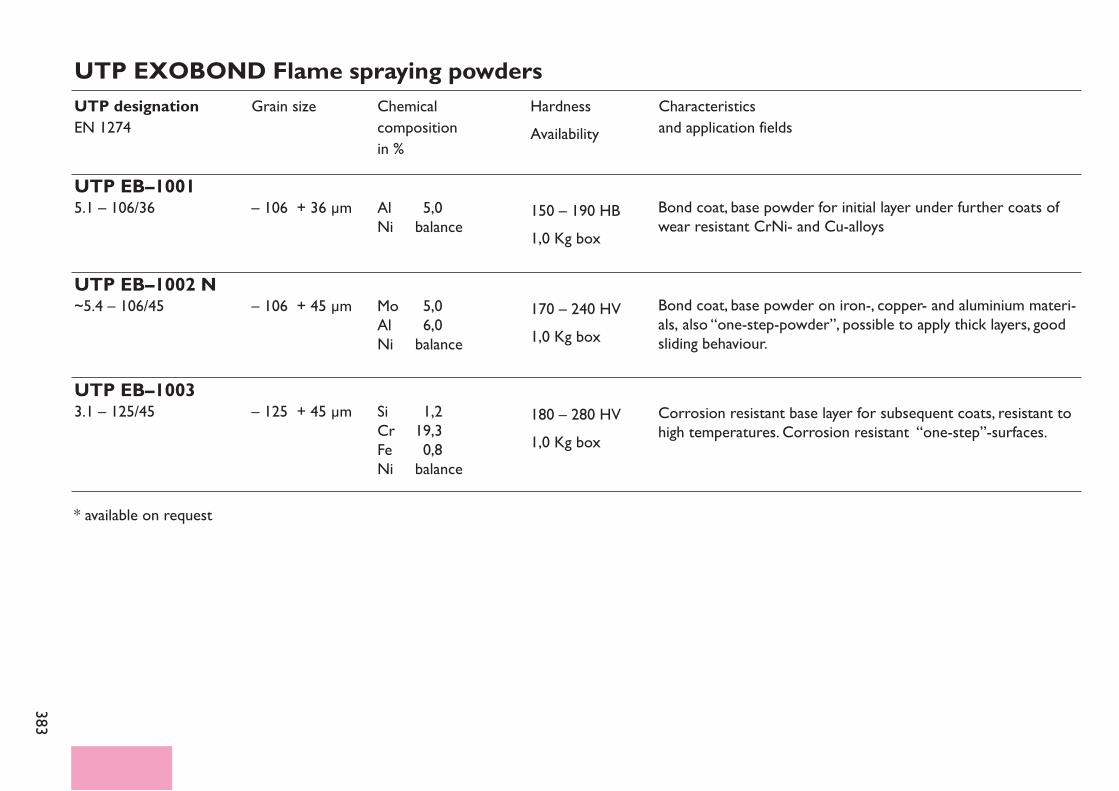
383
UTP EXOBOND Flame spraying powdersUTP designationEN 1274
UTP EB–10015.1 – 106/36
Grain size
– 106 + 36 µm
Chemical compositionin %
Characteristicsand application fields
HardnessAvailability
150 – 190 HB1,0 Kg box
Al 5,0Ni balance
UTP EB–1002 N~5.4 – 106/45 – 106 + 45 µm 170 – 240 HV
1,0 Kg boxMo 5,0Al 6,0Ni balance
UTP EB–10033.1 – 125/45 – 125 + 45 µm 180 – 280 HV
1,0 Kg boxSi 1,2Cr 19,3Fe 0,8Ni balance
* available on request
Bond coat, base powder for initial layer under further coats ofwear resistant CrNi- and Cu-alloys
Bond coat, base powder on iron-, copper- and aluminium materi-als, also “one-step-powder”, possible to apply thick layers, goodsliding behaviour.
Corrosion resistant base layer for subsequent coats, resistant tohigh temperatures. Corrosion resistant “one-step”-surfaces.
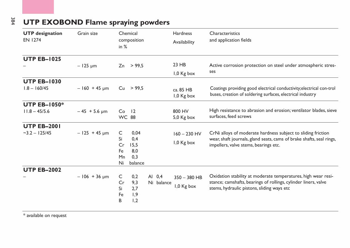
384 UTP EXOBOND Flame spraying powdersUTP designationEN 1274
Grain size Chemical compositionin %
Characteristicsand application fields
HardnessAvailability
UTP EB–10301.8 – 160/45 – 160 + 45 µm ca. 85 HB
1,0 Kg boxCu > 99,5
UTP EB–1025– – 125 µm 23 HB
1,0 Kg boxZn > 99,5
UTP EB–1050*11.8 – 45/5.6 – 45 + 5.6 µm 800 HV
5,0 Kg boxCo 12WC 88
UTP EB–2001~3.2 – 125/45 – 125 + 45 µm 160 – 230 HV
1,0 Kg boxC 0,04Si 0,4Cr 15,5Fe 8,0Mn 0,3Ni balance
UTP EB–2002– – 106 + 36 µm 350 – 380 HB
1,0 Kg boxC 0,2 Al 0,4Cr 9,3 Ni balanceSi 2,7Fe 1,9B 1,2
* available on request
Active corrosion protection on steel under atmospheric stres-ses
Coatings providing good electrical conductivity;electrical con-trolbuses, creation of soldering surfaces, electrical industry
High resistance to abrasion and erosion; ventilator blades, sievesurfaces, feed screws
CrNi alloys of moderate hardness subject to sliding frictionwear, shaft journals, gland seats, cams of brake shafts, seal rings,impellers, valve stems, bearings etc.
Oxidation stability at moderate temperatures, high wear resi-stance; camshafts, bearings of rollings, cylinder liners, valvestems, hydraulic pistons, sliding ways etc
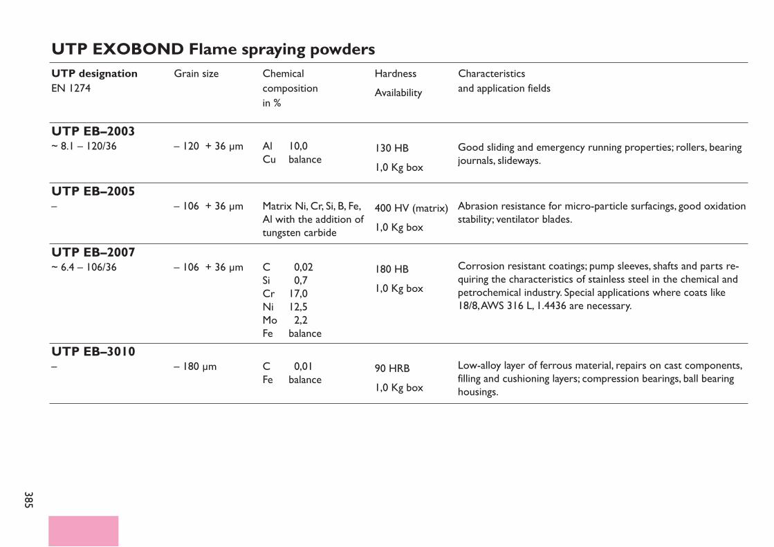
385
UTP EXOBOND Flame spraying powdersUTP designationEN 1274
Grain size Chemical compositionin %
Characteristicsand application fields
HardnessAvailability
UTP EB–2003~ 8.1 – 120/36 – 120 + 36 µm 130 HB
1,0 Kg boxAl 10,0Cu balance
UTP EB–2005– – 106 + 36 µm 400 HV (matrix)
1,0 Kg boxMatrix Ni, Cr, Si, B, Fe,Al with the addition oftungsten carbide
UTP EB–2007~ 6.4 – 106/36 – 106 + 36 µm 180 HB
1,0 Kg boxC 0,02Si 0,7Cr 17,0Ni 12,5Mo 2,2Fe balance
UTP EB–3010– – 180 µm 90 HRB
1,0 Kg boxC 0,01Fe balance
Low-alloy layer of ferrous material, repairs on cast components,filling and cushioning layers; compression bearings, ball bearinghousings.
Corrosion resistant coatings; pump sleeves, shafts and parts re-quiring the characteristics of stainless steel in the chemical andpetrochemical industry. Special applications where coats like18/8, AWS 316 L, 1.4436 are necessary.
Abrasion resistance for micro-particle surfacings, good oxidationstability; ventilator blades.
Good sliding and emergency running properties; rollers, bearingjournals, slideways.
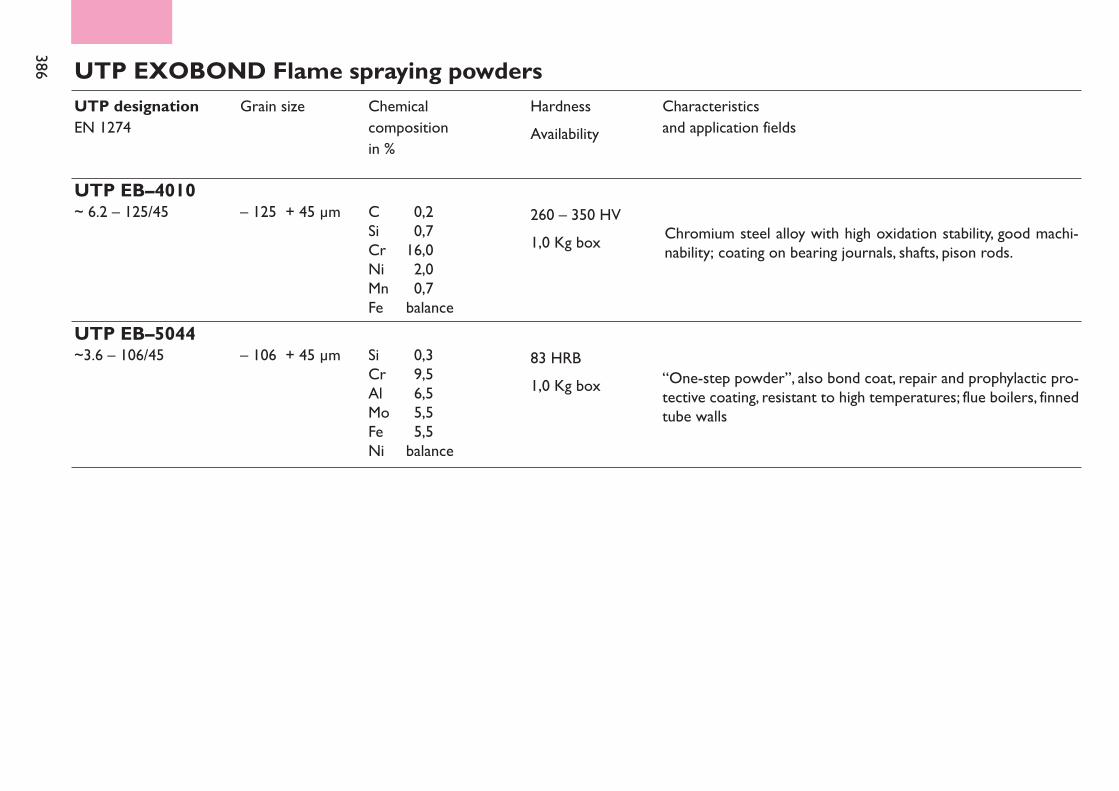
386 UTP EXOBOND Flame spraying powdersUTP designationEN 1274
Grain size Chemical compositionin %
Characteristicsand application fields
HardnessAvailability
UTP EB–4010~ 6.2 – 125/45 – 125 + 45 µm 260 – 350 HV
1,0 Kg boxC 0,2Si 0,7Cr 16,0Ni 2,0Mn 0,7Fe balance
UTP EB–5044~3.6 – 106/45 – 106 + 45 µm
“One-step powder”, also bond coat, repair and prophylactic pro-tective coating, resistant to high temperatures; flue boilers, finnedtube walls
83 HRB1,0 Kg box
Si 0,3Cr 9,5Al 6,5Mo 5,5Fe 5,5Ni balance
Chromium steel alloy with high oxidation stability, good machi-nability; coating on bearing journals, shafts, pison rods.
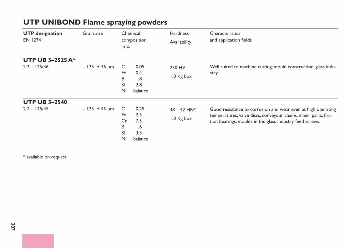
387
UTP UNIBOND Flame spraying powdersUTP designationEN 1274
Grain size Chemical compositionin %
Characteristicsand application fields
HardnessAvailability
UTP UB 5–2525 A*2.2 – 125/36 – 125 + 36 µm Well suited to machine cutting; mould construction, glass indu-
stry.230 HV1,0 Kg box
C 0,05Fe 0,4B 1,8Si 2,8Ni balance
* available on request.
UTP UB 5–25402.7 – 125/45 – 125 + 45 µm 38 – 42 HRC
1,0 Kg boxC 0,25Fe 2,5Cr 7,5B 1,6Si 3,5Ni balance
Good resistance to corrosion and wear even at high operatingtemperatures; valve discs, conveyour chains, mixer parts, fric-tion bearings, moulds in the glass industry, feed screws.
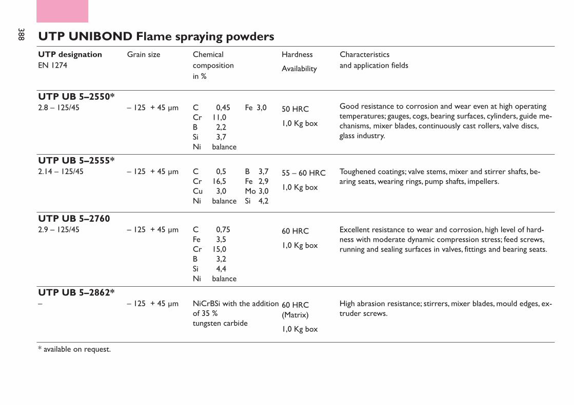
388 UTP UNIBOND Flame spraying powdersUTP designationEN 1274
Grain size Chemical compositionin %
Characteristicsand application fields
HardnessAvailability
UTP UB 5–2550*2.8 – 125/45 – 125 + 45 µm 50 HRC
1,0 Kg boxC 0,45 Fe 3,0Cr 11,0B 2,2Si 3,7Ni balance
UTP UB 5–2555*2.14 – 125/45 – 125 + 45 µm 55 – 60 HRC
1,0 Kg boxC 0,5 B 3,7Cr 16,5 Fe 2,9Cu 3,0 Mo 3,0Ni balance Si 4,2
* available on request.
UTP UB 5–27602.9 – 125/45 – 125 + 45 µm 60 HRC
1,0 Kg boxC 0,75Fe 3,5Cr 15,0B 3,2Si 4,4Ni balance
UTP UB 5–2862*– – 125 + 45 µm 60 HRC
(Matrix)1,0 Kg box
NiCrBSi with the additionof 35 %tungsten carbide
Good resistance to corrosion and wear even at high operatingtemperatures; gauges, cogs, bearing surfaces, cylinders, guide me-chanisms, mixer blades, continuously cast rollers, valve discs,glass industry.
Toughened coatings; valve stems, mixer and stirrer shafts, be-aring seats, wearing rings, pump shafts, impellers.
Excellent resistance to wear and corrosion, high level of hard-ness with moderate dynamic compression stress; feed screws,running and sealing surfaces in valves, fittings and bearing seats.
High abrasion resistance; stirrers, mixer blades, mould edges, ex-truder screws.

389
UTP UNIBOND Flame spraying powdersUTP designationEN 1274
UTP UB 5–2756 X4*–
Grain size
– 125 + 45 µm
Chemical compositionin %
Characteristicsand application fields
HardnessAvailability
55 HRC(Matrix)3,5 Kg box
NiCrBSiwith the addition of 45 % tungsten carbide
UTP UB 5–2871*– – 60 – 65 HRC
(Matrix)3,5 Kg box
NiCrBSiwith the addition of 60 % tungsten carbide
UTP UB 5–2864*–UTP UB 5–2864 4*–
– 125 + 45 µmU– 106 + 20 µm
60 HRC(Matrix)5,0 Kg box
NiCrBSiwith the addition of 50 % tungsten carbide
* available on request
Special mixing powder with high abrasive wear resistance,also particularly suited for thin coating thick-ness applicati-ons, such as mould edges, scrapers, knives.
Highest abrasion resistance; mandrels, cylinder screwshafts, excavator parts.
Powder flame spraying with simultaneous/belated fusingfor the semiautomatic and fully automatic process of hard-facing on high wear resistant surfaces. Conveyor chains, Screw conveyors.
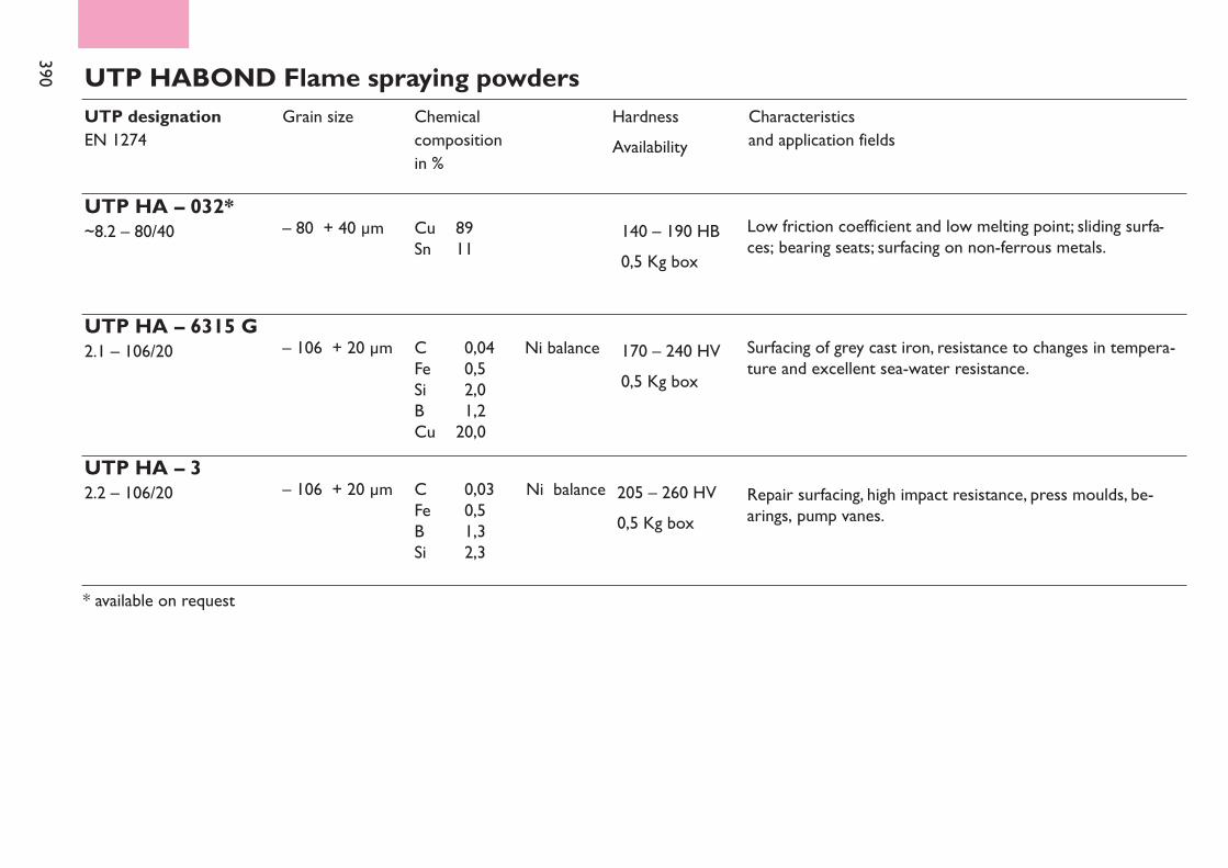
390 UTP HABOND Flame spraying powdersUTP designationEN 1274
UTP HA – 032*~8.2 – 80/40
Grain size
– 80 + 40 µm
Chemical compositionin %
Characteristicsand application fields
HardnessAvailability
140 – 190 HB0,5 Kg box
Cu 89Sn 11
UTP HA – 6315 G2.1 – 106/20 – 106 + 20 µm 170 – 240 HV
0,5 Kg boxC 0,04 Ni balanceFe 0,5Si 2,0B 1,2Cu 20,0
UTP HA – 32.2 – 106/20 – 106 + 20 µm 205 – 260 HV
0,5 Kg boxC 0,03 Ni balanceFe 0,5B 1,3Si 2,3
* available on request
Repair surfacing, high impact resistance, press moulds, be-arings, pump vanes.
Surfacing of grey cast iron, resistance to changes in tempera-ture and excellent sea-water resistance.
Low friction coefficient and low melting point; sliding surfa-ces; bearing seats; surfacing on non-ferrous metals.
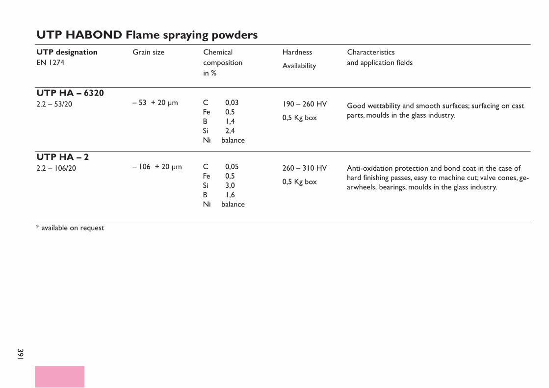
391
UTP HABOND Flame spraying powdersUTP designationEN 1274
Grain size Chemical compositionin %
Characteristicsand application fields
HardnessAvailability
UTP HA – 63202.2 – 53/20 – 53 + 20 µm 190 – 260 HV
0,5 Kg boxC 0,03Fe 0,5B 1,4Si 2,4Ni balance
UTP HA – 22.2 – 106/20 – 106 + 20 µm 260 – 310 HV
0,5 Kg boxC 0,05Fe 0,5Si 3,0B 1,6Ni balance
* available on request
Good wettability and smooth surfaces; surfacing on castparts, moulds in the glass industry.
Anti-oxidation protection and bond coat in the case ofhard finishing passes, easy to machine cut; valve cones, ge-arwheels, bearings, moulds in the glass industry.
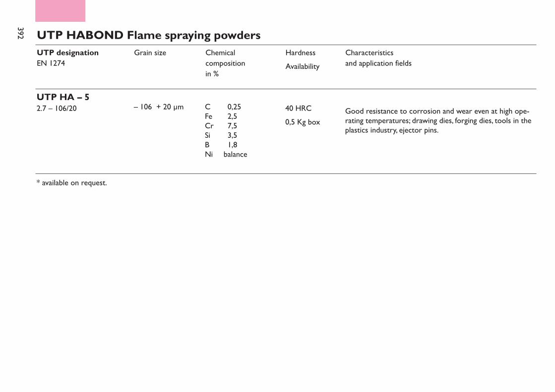
392 UTP HABOND Flame spraying powdersUTP designationEN 1274
Grain size Chemical compositionin %
Characteristicsand application fields
HardnessAvailability
UTP HA – 52.7 – 106/20 – 106 + 20 µm 40 HRC
0,5 Kg boxC 0,25Fe 2,5Cr 7,5Si 3,5B 1,8Ni balance
* available on request.
Good resistance to corrosion and wear even at high ope-rating temperatures; drawing dies, forging dies, tools in theplastics industry, ejector pins.
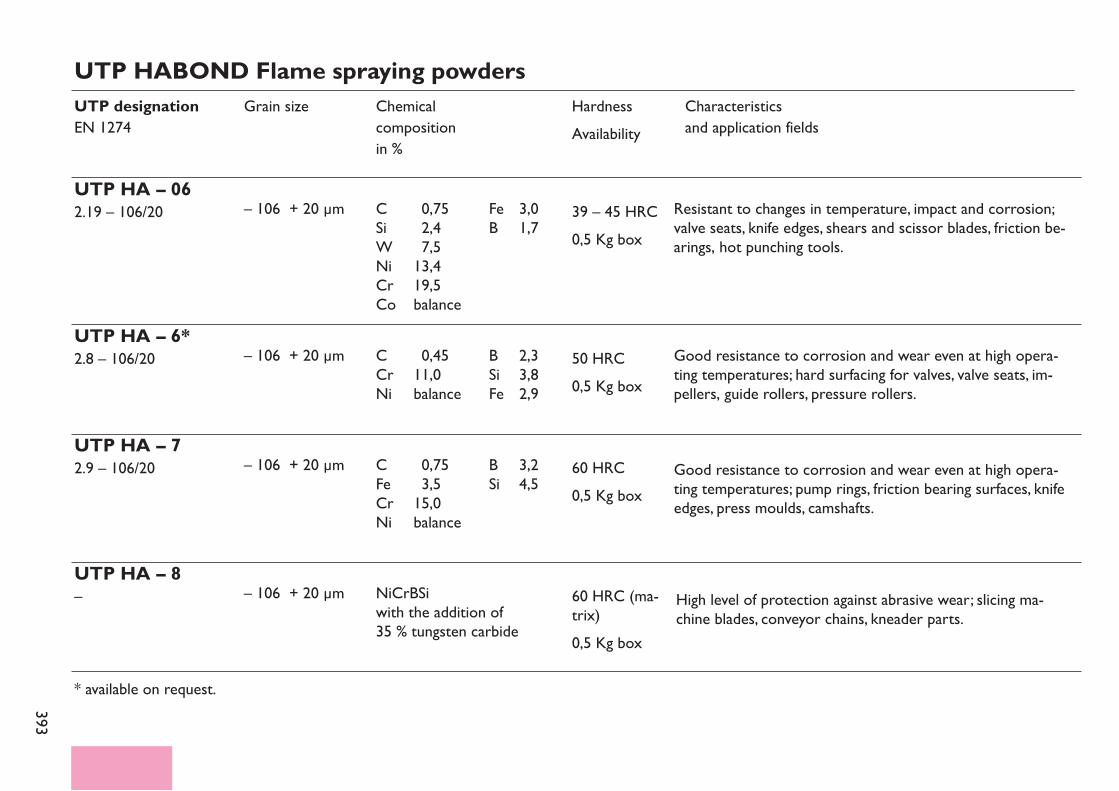
393
UTP HABOND Flame spraying powdersUTP designationEN 1274
Grain size Chemical compositionin %
Characteristicsand application fields
HardnessAvailability
UTP HA – 062.19 – 106/20 – 106 + 20 µm 39 – 45 HRC
0,5 Kg boxC 0,75 Fe 3,0Si 2,4 B 1,7W 7,5Ni 13,4Cr 19,5Co balance
UTP HA – 6*2.8 – 106/20 – 106 + 20 µm 50 HRC
0,5 Kg boxC 0,45 B 2,3Cr 11,0 Si 3,8Ni balance Fe 2,9
UTP HA – 72.9 – 106/20 – 106 + 20 µm 60 HRC
0,5 Kg boxC 0,75 B 3,2Fe 3,5 Si 4,5Cr 15,0Ni balance
UTP HA – 8– – 106 + 20 µm 60 HRC (ma-
trix)0,5 Kg box
NiCrBSiwith the addition of 35 % tungsten carbide
* available on request.
Resistant to changes in temperature, impact and corrosion;valve seats, knife edges, shears and scissor blades, friction be-arings, hot punching tools.
Good resistance to corrosion and wear even at high opera-ting temperatures; hard surfacing for valves, valve seats, im-pellers, guide rollers, pressure rollers.
Good resistance to corrosion and wear even at high opera-ting temperatures; pump rings, friction bearing surfaces, knifeedges, press moulds, camshafts.
High level of protection against abrasive wear; slicing ma-chine blades, conveyor chains, kneader parts.

394 UTP HABOND Flame spraying powdersUTP designationEN 1274
Grain size Chemical compositionin %
Characteristicsand application fields
HardnessAvailability
UTP HA – 8 SS– – 106 + 20 µm 60 HRC
(matrix)0,5 Kg box
NiCrCoFeBSiwith the addition of 55 % tungsten carbide
UTP HA – 8–65*– – 150 + 20 µm 60 HRC
(matrix)0,5 Kg box
NiCoCrBSiFeW with the addition oftungsten carbide
* available on request.
Highest abrasion resistance; mixer-settler parts and knea-ders in the ceramics industry, die drawing tools, choppingblades, scrapers.
Metal tungsten melting carbide mixing powder for ther-mal spraying and simultaneous melting for the automaticcoating process such as hardfacing of wear intensive sur-faces.
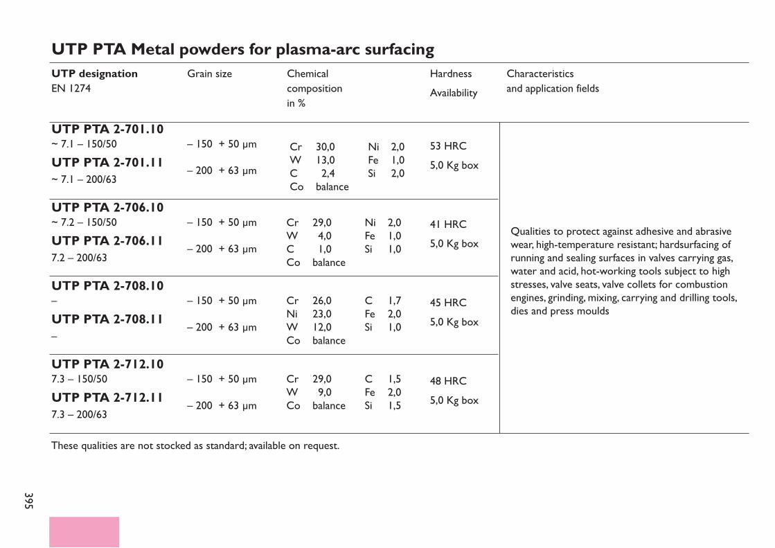
395
UTP PTA Metal powders for plasma-arc surfacingUTP designationEN 1274
UTP PTA 2-701.10~ 7.1 – 150/50UTP PTA 2-701.11~ 7.1 – 200/63
Grain size
– 150 + 50 µm– 200 + 63 µm
Chemical compositionin %
Characteristicsand application fields
HardnessAvailability
53 HRC5,0 Kg box
UTP PTA 2-706.10~ 7.2 – 150/50UTP PTA 2-706.117.2 – 200/63
– 150 + 50 µm– 200 + 63 µm
41 HRC5,0 Kg box
Cr 29,0 Ni 2,0W 4,0 Fe 1,0C 1,0 Si 1,0Co balance
UTP PTA 2-708.10–UTP PTA 2-708.11–
– 150 + 50 µm– 200 + 63 µm
45 HRC5,0 Kg box
Cr 26,0 C 1,7Ni 23,0 Fe 2,0W 12,0 Si 1,0Co balance
UTP PTA 2-712.107.3 – 150/50UTP PTA 2-712.117.3 – 200/63
– 150 + 50 µm– 200 + 63 µm
48 HRC5,0 Kg box
Cr 29,0 C 1,5W 9,0 Fe 2,0Co balance Si 1,5
Cr 30,0 Ni 2,0W 13,0 Fe 1,0C 2,4 Si 2,0Co balance
Qualities to protect against adhesive and abrasivewear, high-temperature resistant; hardsurfacing ofrunning and sealing surfaces in valves carrying gas,water and acid, hot-working tools subject to highstresses, valve seats, valve collets for combustionengines, grinding, mixing, carrying and drilling tools,dies and press moulds
These qualities are not stocked as standard; available on request.
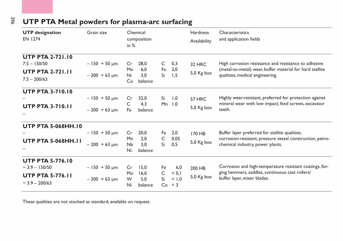
396 UTP PTA Metal powders for plasma-arc surfacingUTP designationEN 1274
UTP PTA 2-721.107.5 – 150/50UTP PTA 2-721.117.5 – 200/63
Grain size
– 150 + 50 µm– 200 + 63 µm
Chemical compositionin %
Characteristicsand application fields
HardnessAvailability
32 HRC5,0 Kg box
Cr 28,0 C 0,3Mo 6,0 Fe 2,0Ni 3,0 Si 1,5Co balance
UTP PTA 3-710.10–UTP PTA 3-710.11–
– 150 + 50 µm– 200 + 63 µm
57 HRC5,0 Kg box
Cr 32,0 Si 1,0C 4,3 Mn 1,0Fe balance
UTP PTA 5-068HH.10–UTP PTA 5-068HH.11–
– 150 + 50 µm– 200 + 63 µm
170 HB5,0 Kg box
Cr 20,0 Fe 2,0Mn 2,0 C 0,05Nb 3,0 Si 0,5Ni balance
UTP PTA 5-776.10~ 3.9 – 150/50UTP PTA 5-776.11~ 3.9 – 200/63
– 150 + 50 µm– 200 + 63 µm
200 HB5,0 Kg box
Cr 15,0 Fe < 6,0Mo 16,0 C < 0,1W 5,0 Si < 1,0Ni balance Co < 3
These qualities are not stocked as standard; available on request.
High corrosion resistance and resistance to adhesive(metal-to-metal) wear, buffer material for hard stellitequalities; medical engineering.
Highly wear-resistant, preferred for protection againstmineral wear with low impact; feed screws, excavatorteeth.
Buffer layer preferred for stellite qualities, corrosion-resistant; pressure vessel construction, petro-chemical industry, power plants.
Corrosion and high-temperature resistant coatings, for-ging hammers, saddles, continuous cast rollers/buffer layer, mixer blades.
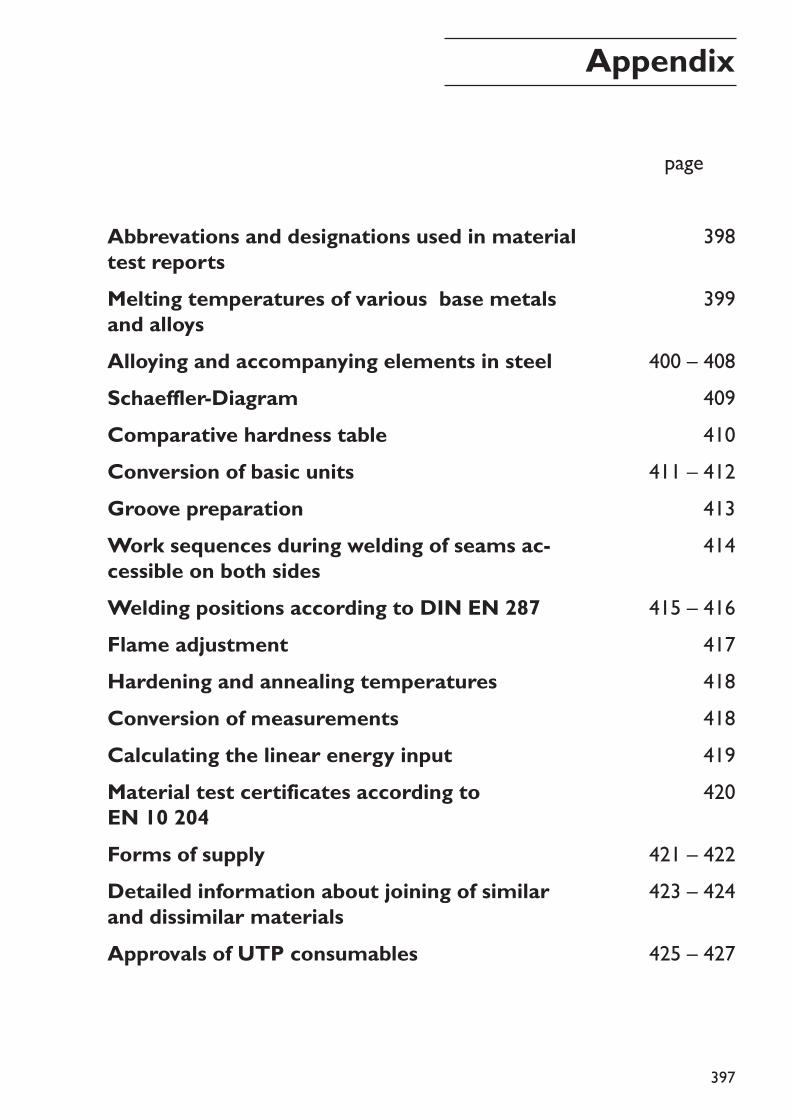
397
398
399
400 – 408409410
411 – 412413414
415 – 416417418418419420
421 – 422423 – 424
425 – 427
pagexxx
Appendix
Abbrevations and designations used in materialtest reportsMelting temperatures of various base metalsand alloysAlloying and accompanying elements in steelSchaeffler-DiagramComparative hardness tableConversion of basic unitsGroove preparationWork sequences during welding of seams ac-cessible on both sidesWelding positions according to DIN EN 287Flame adjustmentHardening and annealing temperaturesConversion of measurementsCalculating the linear energy inputMaterial test certificates according toEN 10 204Forms of supplyDetailed information about joining of similarand dissimilar materialsApprovals of UTP consumables
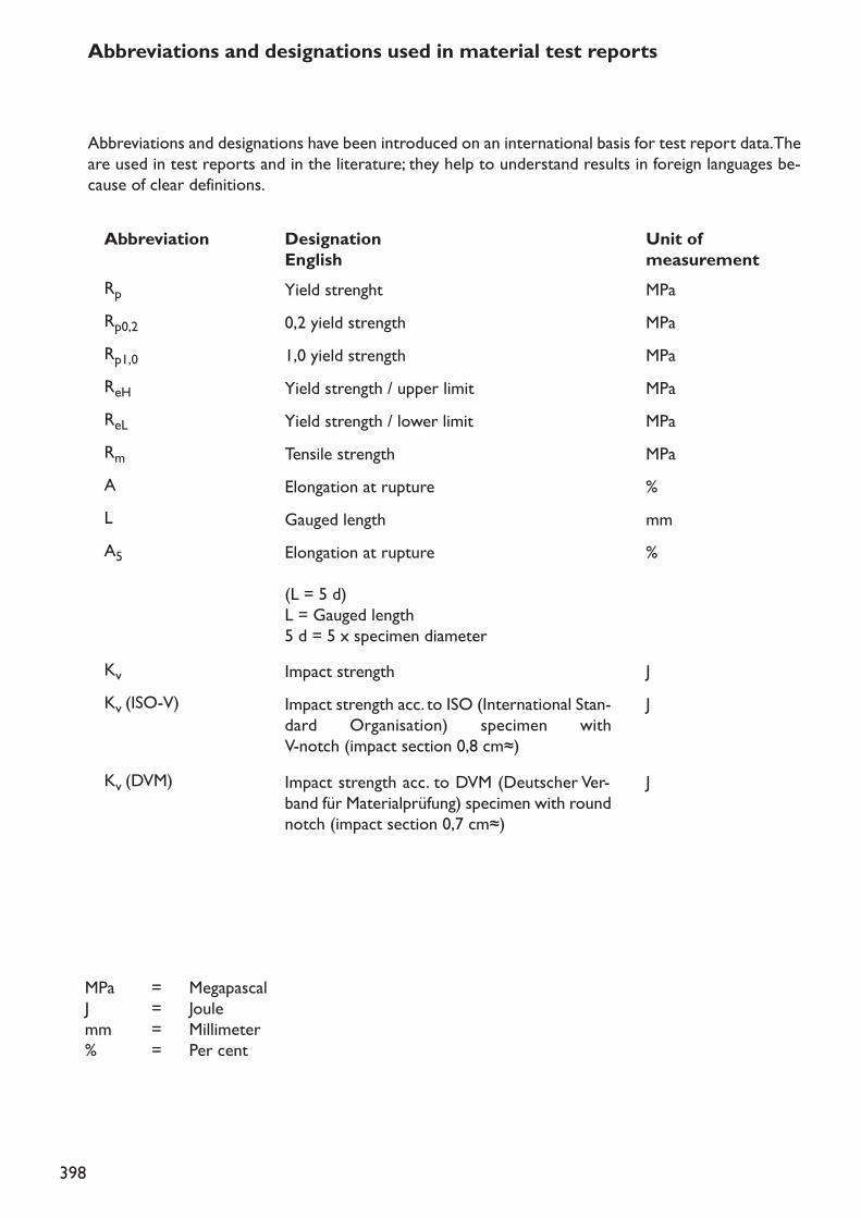
398
MPa = MegapascalJ = Joulemm = Millimeter% = Per cent
Abbreviations and designations used in material test reports
Abbreviations and designations have been introduced on an international basis for test report data. Theare used in test reports and in the literature; they help to understand results in foreign languages be-cause of clear definitions.
AbbreviationRp Yield strenght MPaRp0,2 0,2 yield strength MPaRp1,0 1,0 yield strength MPaReH Yield strength / upper limit MPaReL Yield strength / lower limit MPaRm Tensile strength MPaA Elongation at rupture %
A5 Elongation at rupture(L = 5 d)L = Gauged length5 d = 5 x specimen diameter
%
Kv Impact strength JKv (ISO-V) Impact strength acc. to ISO (International Stan-
dard Organisation) specimen with V-notch (impact section 0,8 cm≈)
J
Kv (DVM) Impact strength acc. to DVM (Deutscher Ver-band für Materialprüfung) specimen with roundnotch (impact section 0,7 cm≈)
J
L Gauged length mm
DesignationEnglish
Unit of measurement
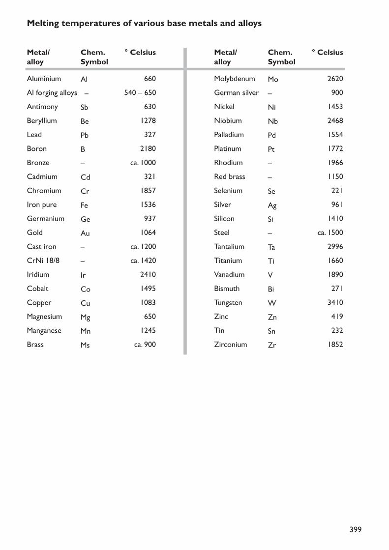
399
Melting temperatures of various base metals and alloys
Metal/alloyAluminium Al 660Al forging alloys – 540 – 650
Cast iron – ca. 1200CrNi 18/8 – ca. 1420Iridium Ir 2410Cobalt Co 1495Copper Cu 1083Magnesium Mg 650Manganese Mn 1245Brass Ms ca. 900
Antimony Sb 630Beryllium Be 1278Lead Pb 327Boron B 2180Bronze – ca. 1000Cadmium Cd 321Chromium Cr 1857Iron pure Fe 1536Germanium Ge 937Gold Au 1064
Chem.Symbol
° Celsius Metal/alloyMolybdenum Mo 2620German silver – 900Nickel Ni 1453Niobium Nb 2468Palladium Pd 1554Platinum Pt 1772Rhodium – 1966Red brass – 1150
Steel – ca. 1500
Selenium Se 221Silver Ag 961Silicon Si 1410
Tantalium Ta 2996Titanium Ti 1660Vanadium V 1890Bismuth Bi 271Tungsten W 3410Zinc Zn 419Tin Sn 232Zirconium Zr 1852
Chem.Symbol
° Celsius
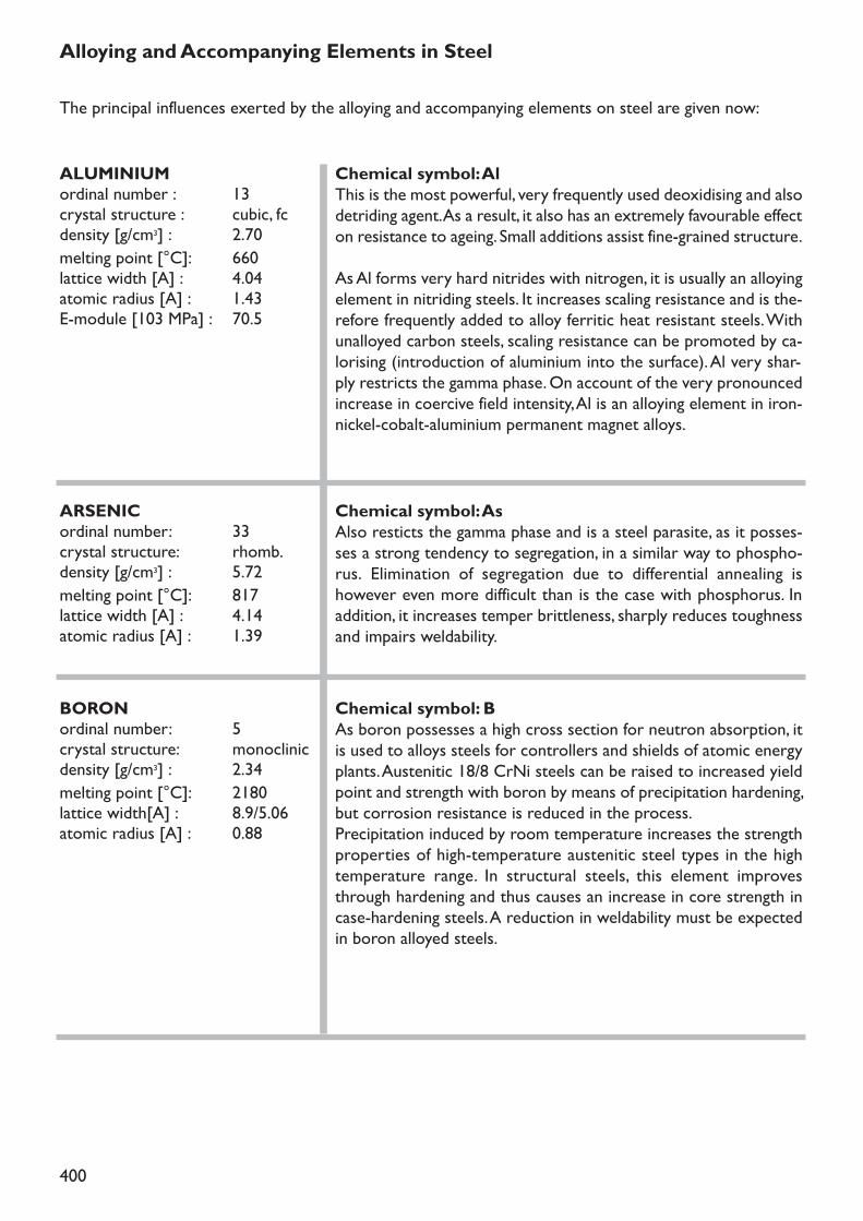
400
Alloying and Accompanying Elements in SteelThe principal influences exerted by the alloying and accompanying elements on steel are given now:
ALUMINIUMordinal number : 13crystal structure : cubic, fcdensity [g/cm3] : 2.70melting point [°C]: 660lattice width [A] : 4.04atomic radius [A] : 1.43E-module [103 MPa] : 70.5
Chemical symbol: AlThis is the most powerful, very frequently used deoxidising and alsodetriding agent. As a result, it also has an extremely favourable effecton resistance to ageing. Small additions assist fine-grained structure.As Al forms very hard nitrides with nitrogen, it is usually an alloyingelement in nitriding steels. It increases scaling resistance and is the-refore frequently added to alloy ferritic heat resistant steels. Withunalloyed carbon steels, scaling resistance can be promoted by ca-lorising (introduction of aluminium into the surface). Al very shar-ply restricts the gamma phase. On account of the very pronouncedincrease in coercive field intensity, Al is an alloying element in iron-nickel-cobalt-aluminium permanent magnet alloys.
ARSENICordinal number: 33crystal structure: rhomb.density [g/cm3] : 5.72melting point [°C]: 817lattice width [A] : 4.14atomic radius [A] : 1.39
Chemical symbol: AsAlso resticts the gamma phase and is a steel parasite, as it posses-ses a strong tendency to segregation, in a similar way to phospho-rus. Elimination of segregation due to differential annealing ishowever even more difficult than is the case with phosphorus. Inaddition, it increases temper brittleness, sharply reduces toughnessand impairs weldability.
BORONordinal number: 5crystal structure: monoclinicdensity [g/cm3] : 2.34melting point [°C]: 2180lattice width[A] : 8.9/5.06atomic radius [A] : 0.88
Chemical symbol: BAs boron possesses a high cross section for neutron absorption, itis used to alloys steels for controllers and shields of atomic energyplants. Austenitic 18/8 CrNi steels can be raised to increased yieldpoint and strength with boron by means of precipitation hardening,but corrosion resistance is reduced in the process.Precipitation induced by room temperature increases the strengthproperties of high-temperature austenitic steel types in the hightemperature range. In structural steels, this element improvesthrough hardening and thus causes an increase in core strength incase-hardening steels. A reduction in weldability must be expectedin boron alloyed steels.
401
CERordinal number: 58crystal structure: hexagonaldensity [g/cm3] :melting point [°C]:lattice width [A] :atomic radius [A] :E-module [103 MPa] :
Chemical symbol: CeHas a purifying action, as it deoxidises pronouncedly and promotesdesulphurisation. It is frequently used in conjunction with lantha-num, neodymium, praseodymium and other rare earth metals as acomposite metal.In high alloy steels, to some extent promotes hot forming proper-ties and improves scale resistance in heat resisting steels. Fe-Ce al-loys with approximately 70 % Ce are pyrophoric (flint stones).Addition to spheroidal graphite cast iron.
BERYLLIUMordinal number: 4crystal structure: hexagonaldensity [g/cm3] : 1.278melting point[°C]: 1290lattice width [A] : 2.3/3.58atomic radius [A] : 1.12E-module [103 MPa] : 310
Chemical symbol: BeVery pronounced restriction of the gamma phase. With Be it is pos-sible to carry out preciptation hardening, but toughness is reducedin the process. Pronouncedly deoxidising, considerable affinity forsulphur. Not very often used as accompanying element in steels.
CARBONordinal number: 6crystal structure: hexagonaldensity [g/cm3] : 3.51atomic radius [A] : 0.77E-module [103 MPa] : 920
Chemical symbol: CCarbon is the most important and influential alloying element insteel. In addition to carbon however, any unalloyed steel will containsilicon, manganese, phosphorus and sulphur, which occur uninten-tionally during manufacture. The addition of further alloying ele-ments to achieve special effects and intentional increase in themanganese and silicon contents result in alloy steels.With increasing C content, the strength and hardenability of thesteel increase, but its ductility, forgeability, weldability and machina-bility (using cutting machine tools) are reduced. Corrosion resi-stance to water, acids and hot gases are practically unaffected by thecarbon.
CALCIUMordinal number: 20crystal structure: krzdensity [g/cm3] : 1.55melting point [°C]: 840lattice width [A] : 5.56atomic radius [A] : 1.97E-module [103 MPa] : 19.6
Chemical symbol: CaUsed together with Si in the form of silicon-calcium for deoxidation.Ca increases scaling resistance of heating conductor materials.
402
COBALTordinal number: 27crystal structure : hexagonaldensity [g/cm3] : 8.89melting point [°C]: 1495lattice width [A] : 2.51/4.1atomic radius [A] : 1.25E-module [103 MPa] : 204
Chemical symbol: CoCo inhibits grain growth at elevated temperatures and pronoun-cedly improves retention of temper and high temperature strength.Therefore, used frequently as alloying element in high speed steels,hot forming tool steels, creep-resistant and high temperature ma-terials. Promotes graphite formation.In large quantities, increases remanence, coercive field intensity andthermal conductivity. Therefore, alloying base for super high qualitypermanent magnet steels and alloys. Under the influence of neutralirradiation, the pronouncedly radioactive isotopes, Co is formed, forwhich reason Co is undesirable in steels for atomic reactors.
CHROMIUMordinal number: 24crystal structure: krzdensity [g/cm3] : 7.19melting point[°C]: 1857lattice width [A] : 2.89atomic radius [A] : 1.27E-module [103 MPa] : 127
Chemical symbol: CrCr renders steels oil and air-hardenable. By reduction of the criti-cal rate of cooling necessary for martensite formation, it increaseshardenability, thus improving its susceptibility to hardening and tem-pering. Notch toughness is reduced however, but ductility suffersonly very slightly.Weldability decreases in pure chromium steels with increasing Crcontent. The tensile strength of the steel increases by 80 - 100 MPaper 1 % Cr.Cr is a carbide former. Its carbides increase the edge-holding qua-lity and wear resistance. High temperature strength and high-pres-sure hydrogenation properties are promoted by chromium. Whilstincreasing Cr contents improve scaling resistance, a minimum con-tent of about 13 % chromium is necessary for corrosion resistanceof steels; this must be dissolved in the matrix.The element restricts the gamma phase and thus extends the fer-rite range. It does however stabilize the austenite in austentic Cr-Mn and Cr-Ni steels. Thermal and electrical conductivity re reduced.Thermal expansion is reduced (alloys for glass sealing). With simul-taneously increased carbon content, Cr contents up to 3 % increaseremanence and coercive field intensity.
COPPERordinal number: 29crystal structure: kfzdensity [g/cm3] : 8.96melting point [°C]: 1083lattice width [A] : 3.61atomic radius [A] : 1.28E-module [103 MPa] : 123
Chemical symbol: CuCopper is added to very few steel alloys, as it concentrates underthe layer of scale and through penetrating into the grain boundary,causes high surface sensitivity in hot forming processes, for whichreason it is regarded as a steel parasite.The yield strength and the yield point/strength ratio are increased.Contents above 0.30 % can cause precipitation hardening. Harde-nability is improved. Weldability is not affected by copper in alloyand low alloy steels, Cu produces significant improvement in we-athering resistance. In acid resistant high alloy steels, a Cu contentabove 1 % produces improvement in resistance to hydrochloric acidand sulphuric acid.
403
MAGNESIUMordinal number: 12crystal structure: hexagonaldensity [g/cm3] : 1.74melting point [°C]: 650lattice width [A] : 3.21/5.2atomic radius [A] : 1.60E-module [103 MPa] : 44.3
Chemical symbol: MgPromotes spheroidal graphite formation in cast iron
MANGANESEordinal number: 25crystal structure: cubic, bcdensity [g/cm3] : 7.43melting point [°C]: 1245lattice width [A] : 3.89atomic radius [A] : 1.26E-module [103 MPa] : 208
Chemical symbol: MnManganese deoxidises. It compounds with sulphur to form Mn sul-phide, thus reducing the undesirable effect of the iron sulphide. Thisis of particular importance in free-cutting steel; it reduces the riskof red shortness.Ar3 and Ar1 are decreased by Mn addition. It very pronoucedly re-duces the critical cooling rate, thus increasing hardenability. Yieldstrength is increased by addition of Mn and, in addition, Mn facou-rably affects forgeability and weldability and pronouncedly increaseshardness penetration depth. Contents > 4 % also lead with slowcooling to formation of brittle martensitic structure, so that the al-loying range is hardly used.Steels with Mn contens > 12 % are austenitic if the carbon contentis also high, because Mn considerably extends the gamma phase.Such steels are prone to very high degree of strain hardening wherethe surface is subjected to impact stress, whilst the core remainstough. For this reason, they are highly resistant to wear under theinfluence of impact.Steels with Mn contents of > 18 % remain unmagnetisable even afterrelatively pronounced cold forming and are used as special steels aswell as steels remaining tough at subzero temperatures which aresubjected to low temperature stress.The coefficient of thermal expansion increases as a result of Mn,whilst thermal and electrical conductivity are reduced.
HYDROGENordinal number: 1crystal structure: hexagonaldensity [g/cm3] : 0.0899*10-3melting point [°C]: -252.9lattice width [A]: 3.75/6.1
Chemical symbol: HHydrogen is a steel parasite because it causes embrittlementthrough reduction of ductility and necking without increasing yieldstrength and tensile strength. It is cause of undesirable flaking andpromotes the occurence of ghost lines. Atomic hydrogen occuringduring pickling penetrates the steel, forming pitting. Moist hydrogendecarburises at elevated temperatures.
404
NICKELordinal number: 28crystal structure: cubic, bcdensity [g/cm3] : 8.90melting point [°C]: 1453lattice width [A] : 3.52atomic radius [A] : 1.24E-module [103 MPa] : 202
Chemical symbol: NiWith structural steels produces significant increase in notchtoughness, even in the low temperature range, and is therefore al-loyed for increasing toughness in case-hardening, heat-treatable andsubzero toughness steels.All transformation points (A1 - A4) are lowered by Ni; it is not a car-bide former. As result of pronounced extension of the gamma phase,Ni in contents of > 7 % imparts austenitic structure to chemicallyresistant steels down to well below room temperature. Ni on itsown makes the steel rust resistant, even in high percentages, but inaustenitic Cr-Ni steels
NIOBIUMordinal number: 41crystal structure: cubic, bcdensity [g/cm3] : 8.57melting point [°C]: 2468lattice width [A] : 3.30atomic radius [A] : 1.46E-module [103 MPa] : 104
Chemical symbol: NbNiobium is a very pronounced carbide former, thus alloyed parti-cularly as stabilizers of chemical resistant steels. Nb is a ferrite for-mer and thus reduces the gamma phase. On account of the increasein high temperature strength and creep rupture strength due to Nb,it is frequently alloyed to high-temperature austenitic boiler steelsand high speed steels.
MOLYBDENUMordinal number: 42crystal structure: cubic, bcdensity [g/cm3] : 10.22melting point [°C]: 2620lattice width [A] : 3.15atomic radius [A] : 1.39E-module [103 MPa] : 301
Chemical symbol: MoMo is usually alloyed together with other elements. Reducing thecritical cooling rate improves hardenability. Mo significantly reducestemper brittleness, for example in the case of CrNi and Mn steels,promotes fine grain formation and also favourably affects weldabi-lity. Increase in yield point and strength. With increased Mo content,forgebility is reduced. Pronounced carbide former; cutting proper-ties with high speed steel are improved thereby.It belongs to the elements which increase corrosion resistance andis therefore used frequently with high alloy Cr steels and with aus-tenitic CrNi steels. High Mo contents reduce susceptibility to pit-ting. Very strong reduction of the austenitic area. Increased hightemperature strength, scaling resistance is reduced.
NITROGENordinal number: 7crystal structure: hexagonaldensity [g/cm3] : 1.25* 10-3melting point [°C]: - 195.8atomic radius [A] : 0.77
Chemical symbol: NThis element can occur both as a steel parasite and as an alloyingelement. Parasitic because of the reduction in toughness throughprecipitation processes, causing susceptibility to ageing and bluebrittleness (deformation in the blue heat range of 300 - 350° C) andan account of the possibility of initiation of intercrystalline stresscracks in unalloyed and low alloy steels.As an alloying element, N extends the gamma phase and stabilizesthe austenitic structure. In austenitic steels N increases strengthand above all the yield strength plus mechanical properties in heat.As a result of nitride formation during nitriding, N permits high sur-face hardness to be achieved.
405
OXYGENordinal number: 8crystal structure: ortho-
rhomb.density [g/cm3] : 1.429*10-3melting point [°C]: -182.9atomic radius [A] : 0.66
Chemical symbol: OSteel parasite; important for its specific effect are nature and com-position of its compounds in steel as well as form and distribution.The mechanical properties, particularly notch toughness, especiallyin transverse direction, are reduced, whilst the tendency to ageingbrittleness, red shortness, fibrous fracture and fishscale fracture isincreased.
PHOSPHORUSordinal number: 15crystal structure: ortho-
rhomb.density [g/cm3] : 1.83atomic radius [A] : 1.28
Chemical symbol: PIs usually regarded as a steel parasite, as P produces pronouncedprimary segregation an solidification of the melt and the possibilityof secondary segregation in solid state due to the pronounced re-striction of the gamma phase.As a result of the relatively low rate of diffusion, both in the alpha-and in the gamma crystal, segregation which has occurred can onlybe corrected with difficulty. As it is hardly possible to achieve ho-mogeneous distribution of the P1 an attempt is made to keep thephosphorus content very low and accordingly, with high grade steels,to strive for an upper limit of 0.03 - 0.05 %. The extent of segrega-tion cannot be determind with certainty.Even in the smallest quantities, P increases proneness to temperembrittlement. Phosphorus embrittlement increases with the rise inC content, with rising hardening temperature, with grain size andwith decrease of the ratio of reduction by forging. Embrittlement oc-curs as cold shortness and sensitivity to impact stress (tendency tobrittle fracture). In low alloy structural steels with C contents ofabout 0.1 %, P increases strength and corrosion resistance to at-mospheric effects. Cu assists the improvement in corrosion resi-stance (rust resistant steels).In austenitic Cr-Ni steels, additions of P can cause increases in yieldstrength and achieve precipitation effects.
NICKEL(continued)
results in resistance to the effect of chemicals. Resistance of thesesteels in oxidizing substances is achieved by Cr.At temperatures above 600° C, austenitic steels have greater hightemperature strength, as their recrystallisation temperature is high.They are practically unmagnetisable. Thermal and electrical con-ductivity are significantly reduced. High Ni contents in precisely de-fined alloying ranges lead to physical steels with certain physicalproperties, low thermal expansion (Invar types).
406
SELENIUMordinal number: 34crystal structure: rhomb.density [g/cm3] : 4.19melting point [°C]: 221atomic radius [A] : 1.40
Chemical symbol: SeUsed in free-cutting steels in a similar way to sulphur, it being in-tended to improve machinability even more effectively.In corrosion resistant steels, it reduces resistance to a lesser de-gree than sulphur.
LEADordinal number: 82crystal structure: kfzdensity [g/cm3] : 11.36melting point [°C]: 327lattice width [A] : 4.95atomic radius [A] : 1.75E-module [103 MPa] : 16.2
Chemical symbol: PbIs added to cutting tool steels in contents of about 0.2 - 0.5 % as, byvirtue of its extremely fine suspension-like distribution, formation ofshorter chips and clean faces of cut are achieved, thus improvingmachinability. The lead contents stated hardly affect the mechanicalproperties of the steel at all.
SULPHURordinal number: 16crystal structure: ortho-
rhomb.density [g/cm3] : 2.07melting point [°C]: 119atomic radius [A] : 1.27
Chemical symbol: SProduces the most pronounced segregation of all steel accompa-nying elements. Iron sulphide, leads to red shortness or hot short-ness, as the low melting point sulphide eutectics surround the grainsin reticular fashion, so that only slight cohesion of the latter occursand during hot forming the grain boundaries tend to break down.This is further increased by the action of oxygen.As sulphur possesses a considerable affinity for manganese, it iscombined in the form of Mn sulphide, as this is the least dangerousof all existing inclusions, being present distributed in point form inthe steel. Toughness in transverse direction is reduced significantlyby S.Sulphur is added intentionally to steels for automatic machining upto 0.4 % as the friction on the tool cutting edge reduced by the tool.In addition, short chips occur when free-cutting steels are machined.Sulphur increases susceptibility to welding cracks.
ANTIMONYordinal number: 51crystal structure: rhomb.density [g/cm3] : 6.62melting point [°C]: 630lattice width [A] : 4.5atomic radius [A] : 1.59E-module [103 MPa] : 54.9
Chemical symbol: SbA steel parasite, as it generally significantly reduces toughness pro-perties; restricts the gamma phase.
407
TANTALUMordinal number: 73crystal structure: cubic, bcdensity [g/cm3] : 16.6melting point [°C]: 2996lattice width [A]: 3.30atomic radius [A] : 1.46E-module [103 MPa]: 175
Chemical symbol: TaThis element occur together with Nb, and they are very difficult toseparate from one another, so that they are usually used together.Very pronounced carbide formers, thus alloyed particularly as sta-bilizers of chemical resistant steels. It is a ferrite former and thus re-duces the gamma phase. Ta has a neutron high absorptioncross-section; only low-Ta Nb steel is considered for use for reac-tor steels.
TELLURICordinal number: 52crystal structure: rhomb.density [g/cm3] : 6.24melting point [°C]: 450lattice width [A]: 4.45/5.9atomic radius [A] : 1.60E-module [103 MPa]: 41.2
Chemical symbol: TeTelluric influences steel properties comparable to selenium, used infree-cutting steels similar to sulphur. Is being intended to improvemachinability even more effectively.In corrosion resistant steels, it reduces resistance to a lesser de-gree than sulphur.Contents up to 0.2 % improve the machinability.
SILICONordinal number: 14crystal structure: diamonddensity [g/cm3] : 2.33melting point [°C]: 1410atomic radius [A] : 1.32E-module [103 MPa]: 113
Chemical symbol: SiSi is contained in all steel in the same way as manganese, as ironores incorporate a quantity of it according to their compostion. Insteel production itself silicon is absorbed into the melt from the re-fractory furnace linings. But only those steels are called silicon steelswhich have a Silicon content of > 0.40 %.Si is not a metal, but a metalloid as are also, for example, phoshorusand sulphur Si deoxidises. It promotes graphite precipitation and re-strics the gamma phase significantly, increases strength and wear re-sistance (Si-Mn heat treatable steels); significant increase in theelastic limit, thus useful alloying element in spring steels.It significantly increases scale resistance, so that such resisting steelsare alloyed with it. The possible content is limited however an ac-count of its imparing hot and cold formability. With 12 % Si, acid re-sistance is achieved to a large extent, but such grades can only beproduced as very hard, brittle steel castings which can be machinedonly by grinding.On account of significant reduction of electrical conductivity, coer-cive field intensity and low wattage loss, Si is used in steels for elec-trical quality sheet.
TINordinal number: 50crystal structure: tetragonaldensity [g/cm3] : 7.30melting point [°C]: 232lattice width [A]: 5.82/3.2atomic radius [A] : 1.62E-module [103 MPa]: 54.3
Chemical symbol: SnSteel parasite as it concentrates like Cu under the scale film, pene-trates along the grain boundaries and causes cracking and solderbrittleness. Sn tends towards pronounced segregation and restrictsthe gamma phase.
408
ZIRCONIUMordinal number: 40crystal structure: hexagonaldensity [g/cm3] : 6.49melting point [°C]: 1852lattice width [A]: 3.23/5.1atomic radius [A] : 1.60E-module [103 MPa]: 92.2
Chemical symbol: ZrCarbide former; metallurgical use as alloying element for deoxida-tion, denitridig and desulphurisation, as it leaves minimal deoxidationproducts behind.Additions of Zr to fully deoxidised sulphur-bearing free-cuttingsteels have a favourable effect on sulphide formation and thus pre-vention of red shortness. It increases the life of heating conductormaterials and produces restriction of the gamma phase.
TUNGSTENordinal number: 74crystal structure: cubic, bcdensity [g/cm3] : 19.3melting point [°C]: 3410lattice width [A]: 3.16atomic radius [A] : 1.39E-module [103 MPa]: 368
Chemical symbol: T (German W)Tungsten is a very pronounced carbide former (its carbides are veryhard) and restricts the gamma phase. It improves toughness and pre-vents grain growth. T increases high temperature strength and re-tention of temper as well as wear resistance at high temperatures(red heat) and thus cutting ability.It is therefore alloyed primarily to high speed and hot forming toolsteels, as well as creep-resistant steel types and to ultra-hard steels.Significant increase in coercive field intensity, thus alloying elementof permanent magnet steel alloys. T impairs scaling resistance. Itshigh specific gravity is particular noticeable in high T-alloy high speedand hot forming tool steels.
TITANIUMordinal number: 22crystal structure: hexagonaldensity [g/cm3] : 4.50melting point [°C]: 1660lattice width [A]: 2.95/4.7atomic radius [A] : 1.47E-module [103 MPa]: 106
Chemical symbol: TiOn account of its very strong affinity for Oxygen, nitrogen, sulphurand carbon, has a pronounced carbide forming action. Used widelyin stainless steels as carbide former for stabilization against inter-cystalline corrosion. Also possesses grain refining properties. Ti restricts the gamma phase very pronouncedly. In high concenta-tion, it leads to precipitation processes and is added to permanentmagnet alloys an account of achieving high coercive field intensity.Ti increases creep rupture strength through formation of special ni-trides. Finally, Ti tends pronouncedly to segregaion and banding.
VANADIUMordinal number: 23crystal structure: cubic, bcdensity [g/cm3] : 5.96melting point [°C]: 1890lattice width [A]: 3.03atomic radius [A] : 1.34E-module [103 MPa]: 127
Chemical symbol: VRefines the primary grain and the casting structure. Pronouncedcarbide former, thus providing increase in wear resistance, edge hol-ding quality and high temperature strength. It is used therefore pri-marily as additional alloying element in high speed, hot forming andcreep resistant steels. Significant improvement in retention of tem-per, reduction of overheating sensitivity. As V refines the grain andinhibits air hardening as a result of carbide formation, it promotesthe weldability of heat treatable steels. Increase in resistance tocompressed hydrogen an account of carbide formation. V restrictsthe gamma phase and shifts the Curie point at elevated temperatu-res.
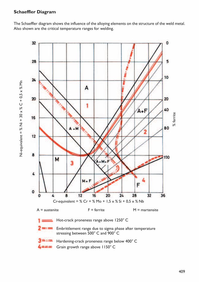
409
% ferrite
Schaeffler DiagramThe Schaeffler diagram shows the influence of the alloying elements on the structure of the weld metal.Also shown are the critical temperature ranges for welding.
Ni-equivalent = % N
i + 30 x % C + 0,5 x
% Mn
Cr-equivalent = % Cr + % Mo + 1,5 x % Si + 0,5 x % NbA = austenite F = ferrite M = martensite
Hot-crack proneness range above 1250° C
Hardening-crack proneness range below 400° CGrain growth range above 1150° C
Embrittlement range due to sigma phase after temperature stressing between 500° C and 900° C

410
Brinell VickersRockwell
80859095100
HB HRB HRC HVBrinell VickersRockwellHB HRB HRC HV
36,442,447,452,056,4
80859095100105110115120125
105110115120125
60,063,466,469,472,0130135140145150
130135140145150
74,476,478,480,482,2155160165170175
155160165170175
83,885,486,888,289,6180185190195200
180185190195200
90,891,893,094,095,0205210215220225
205210215220225
95,896,697,698,299,0230235240245250
230235240245250
19,220,221,222,123,0255260265270275
23,824,625,426,226,9280285290295300
27,628,329,029,630,0310320330340350
255260265270275280285290295300310320330340350
31,532,733,834,936,0
359368376385392
360370380390400
37,038,038,939,840,7400408415423430
410420430440450
41,542,443,244,044,8460470480490500
45,546,347,047,748,8510520530540550
49,049,850,350,951,5560570580590600
52,152,753,353,854,4610620630640650
54,955,455,956,456,9660670680690700
57,457,958,458,959,360,261,161,962,763,564,365,065,766,366,9
72074076078080082084086088090092094067,568,0
Comparative hardness table
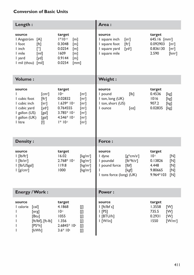
411
Conversion of Basic UnitsLength :source target1 Angström [A] 1*10-10 [m]1 foot [ft] 0.3048 [m]1 inch [“] 0.0254 [m]1 mile [ml] 1609 [m]1 yard [yd] 0.9144 [m]1 mil (thou) [mil] 0.0254 [mm]
Area :source target1 square inch [in2] 645.16 [mm2]1 square foot [ft2] 0.092903 [m2]1 square yard [yd2] 0.836130 [m2]1 square mile 2.590 [km2]
Volume :source target1 [cm3] 10-6 [m3]1 cubic foot [ft3] 0.02832 [m3]1 cubic inch [in3] 1.639* 10-5 [m3]1 cubic yard [yd3] 0.764555 [m3]1 gallon (US) [gal] 3.785* 10-3 [m3]1 gallon (UK) [gal] 4.546* 10-3 [m3]1 litre [l] 1* 10-3 [m3]
Weight :source target1 pound [lb] 0.4536 [kg]1 ton, long (UK) 1016 [kg]1 ton, short (US) 907.2 [kg]1 ounce [oz] 0.02835 [kg]
Density :source target1 [lb/ft3] 16.02 [kg/m3]1 [lb/in3] 2.768* 10-5 [kg/m3]1 [lb/USgal] 119.8 [kg/m3]1 [g/cm3] 1000 [kg/m3]
Force :source target1 dyne [g*cm/s2] 10-5 [N]1 poundal [lb*ft/s2] 0.13826 [N]1 pound force [lbf] 4.448 [N]1 [kgf] 9.80665 [N]1 tons force (long) (UK) 9.964*103 [N]
Energy / Work :source target1 calorie [cal] 4.1868 [J]1 [erg] 10-2 [J]1 [Btu] 1055 [J]1 [ft/lbf], [ft-lb] 1.356 [J]1 [PS*h] 2.6845* 106 [J]1 [kWh] 3.6* 106 [J]
Power :source target1 [ft/lbf s] 1.3558 [W]1 [PS] 735.5 [W]1 [BTU/h] 0.2931 [W]1 [W/in] 1550 [W/m2]
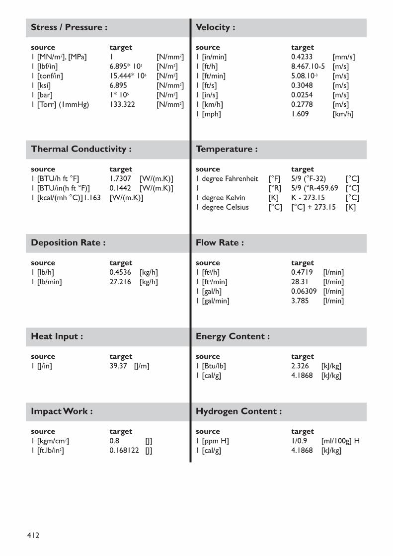
412
Stress / Pressure :source target1 [MN/m2], [MPa] 1 [N/mm2]1 [lbf/in] 6.895* 103 [N/m2]1 [tonf/in] 15.444* 106 [N/m2]1 [ksi] 6.895 [N/mm2]1 [bar] 1* 105 [N/m2]1 [Torr] (1mmHg) 133.322 [N/mm2]
Velocity :source target1 [in/min] 0.4233 [mm/s]1 [ft/h] 8.467.10-5 [m/s]1 [ft/min] 5.08.10-3 [m/s]1 [ft/s] 0.3048 [m/s]1 [in/s] 0.0254 [m/s]1 [km/h] 0.2778 [m/s]1 [mph] 1.609 [km/h]
Temperature :source target1 degree Fahrenheit [°F] 5/9 (°F-32) [°C]1 [°R] 5/9 (°R-459.69 [°C]1 degree Kelvin [K] K - 273.15 [°C]1 degree Celsius [°C] [°C] + 273.15 [K]
Thermal Conductivity :source target1 [BTU/h ft °F] 1.7307 [W/(m.K)]1 [BTU/in(h ft °F)] 0.1442 [W/(m.K)]1 [kcal/(mh °C)]1.163 [W/(m.K)]
Flow Rate :source target1 [ft3/h] 0.4719 [l/min]1 [ft3/min] 28.31 [l/min]1 [gal/h] 0.06309 [l/min]1 [gal/min] 3.785 [l/min]
Heat Input :source target1 [J/in] 39.37 [J/m]
Energy Content :source target1 [Btu/lb] 2.326 [kJ/kg]1 [cal/g] 4.1868 [kJ/kg]
Impact Work :source target1 [kgm/cm2] 0.8 [J]1 [ft.lb/in2] 0.168122 [J]
Hydrogen Content :source target1 [ppm H] 1/0.9 [ml/100g] H1 [cal/g] 4.1868 [kJ/kg]
Deposition Rate :source target1 [lb/h] 0.4536 [kg/h]1 [lb/min] 27.216 [kg/h]
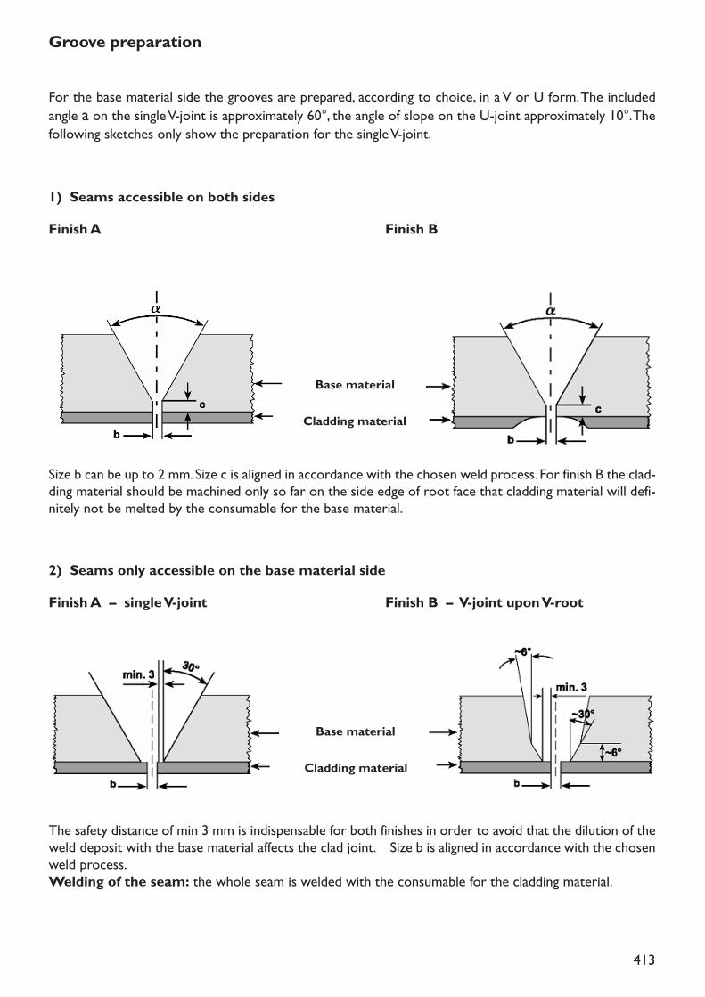
413
Groove preparation
For the base material side the grooves are prepared, according to choice, in a V or U form. The includedangle a on the single V-joint is approximately 60°, the angle of slope on the U-joint approximately 10°. Thefollowing sketches only show the preparation for the single V-joint.
1) Seams accessible on both sidesFinish A Finish B
Base material
Cladding material
Size b can be up to 2 mm. Size c is aligned in accordance with the chosen weld process. For finish B the clad-ding material should be machined only so far on the side edge of root face that cladding material will defi-nitely not be melted by the consumable for the base material.
2) Seams only accessible on the base material sideFinish A – single V-joint Finish B – V-joint upon V-root
Base material
Cladding material
The safety distance of min 3 mm is indispensable for both finishes in order to avoid that the dilution of theweld deposit with the base material affects the clad joint. Size b is aligned in accordance with the chosenweld process.Welding of the seam: the whole seam is welded with the consumable for the cladding material.
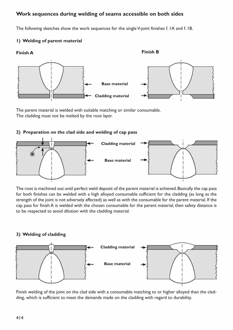
414
Work sequences during welding of seams accessible on both sidesThe following sketches show the work sequences for the single V-joint finishes f. 1A and f. 1B.1) Welding of parent materialFinish A Finish B
Base material
Cladding material
The parent material is welded with suitable matching or similar consumable.The cladding must not be melted by the root layer.
2) Preparation on the clad side and welding of cap passCladding material
Base material
The root is machined out until perfect weld deposit of the parent material is achieved. Basically the cap passfor both finishes can be welded with a high alloyed consumable sufficient for the cladding (as long as thestrength of the joint is not adversely affected) as well as with the consumable for the parent material. If thecap pass for finish A is welded with the chosen consumable for the parent material, then safety distance isto be respected to avoid dilution with the cladding material.
3) Welding of claddingCladding material
Base material
Finish welding of the joint on the clad side with a consumable matching to or higher alloyed than the clad-ding, which is sufficient to meet the demands made on the cladding with regard to durability.
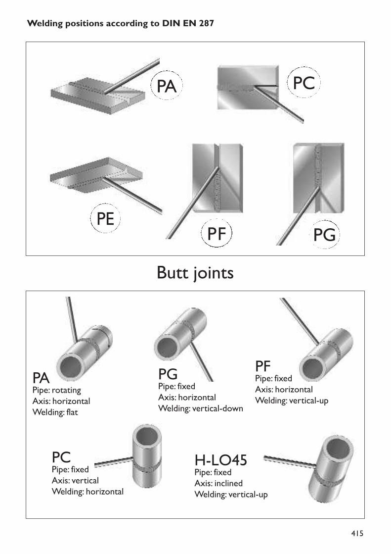
415
Welding positions according to DIN EN 287
PA PC
PGPFPE
Butt joints
PAPipe: rotatingAxis: horizontalWelding: flat
PGPipe: fixedAxis: horizontalWelding: vertical-down
PFPipe: fixedAxis: horizontalWelding: vertical-up
PCPipe: fixedAxis: verticalWelding: horizontal
H-LO45Pipe: fixedAxis: inclinedWelding: vertical-up
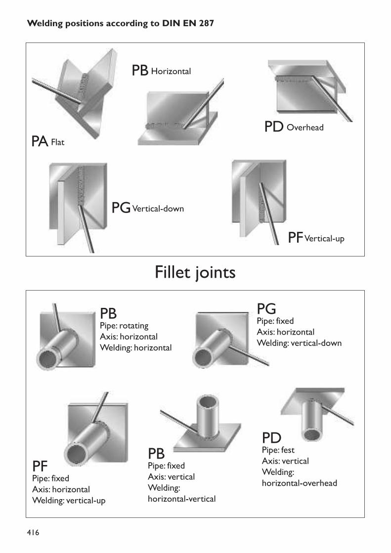
416
Welding positions according to DIN EN 287
Fillet joints
PA Flat
PB Horizontal
PD Overhead
PGVertical-down
PFVertical-up
PBPipe: rotatingAxis: horizontalWelding: horizontal
PFPipe: fixedAxis: horizontalWelding: vertical-up
PBPipe: fixedAxis: verticalWelding: horizontal-vertical
PDPipe: festAxis: verticalWelding: horizontal-overhead
PGPipe: fixedAxis: horizontalWelding: vertical-down
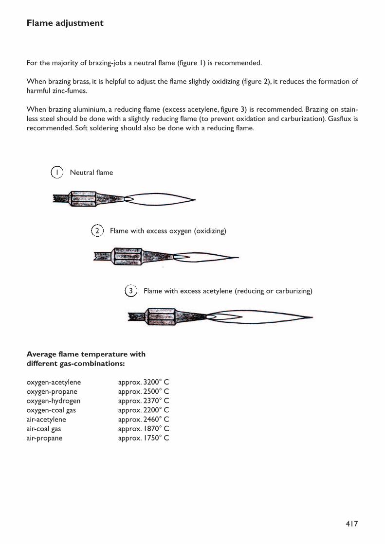
417
Neutral flame1
Flame with excess oxygen (oxidizing)2
Flame with excess acetylene (reducing or carburizing)3
Flame adjustment
For the majority of brazing-jobs a neutral flame (figure 1) is recommended.When brazing brass, it is helpful to adjust the flame slightly oxidizing (figure 2), it reduces the formation ofharmful zinc-fumes.When brazing aluminium, a reducing flame (excess acetylene, figure 3) is recommended. Brazing on stain-less steel should be done with a slightly reducing flame (to prevent oxidation and carburization). Gasflux isrecommended. Soft soldering should also be done with a reducing flame.
Average flame temperature with different gas-combinations:oxygen-acetylene approx. 3200° Coxygen-propane approx. 2500° Coxygen-hydrogen approx. 2370° Coxygen-coal gas approx. 2200° Cair-acetylene approx. 2460° Cair-coal gas approx. 1870° Cair-propane approx. 1750° C
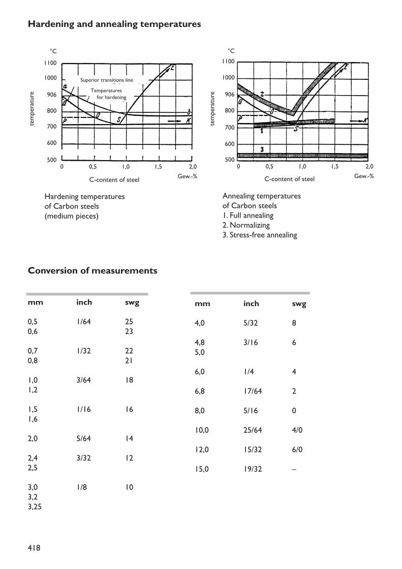
418
Conversion of measurements
mm inch swg0,5 1/64 250,6 230,7 1/32 220,8 211,0 3/64 181,21,5 1/16 161,62,0 5/64 142,4 3/32 122,53,0 1/8 103,23,25
mm inch swg4,0 5/32 84,8 3/16 65,06,0 1/4 46,8 17/64 28,0 5/16 010,0 25/64 4/012,0 15/32 6/015,0 19/32 –
0 0,5
600500
70080090610001100°C
600500
70080090610001100°C
1,0 1,5 2,0Gew.-%C-content of steel
temperature
temperature
0 0,5 1,0 1,5 2,0Gew.-%C-content of steel
Hardening temperaturesof Carbon steels(medium pieces)
Annealing temperaturesof Carbon steels1. Full annealing2. Normalizing3. Stress-free annealing
Temperatures for hardening
Superior transitions line
Hardening and annealing temperatures
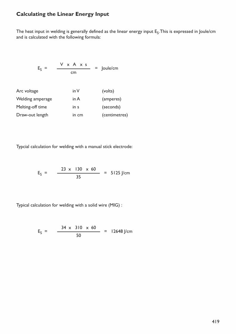
419
Calculating the Linear Energy Input
The heat input in welding is generally defined as the linear energy input ES. This is expressed in Joule/cmand is calculated with the following formula:
Typcial calculation for welding with a manual stick electrode:
Typical calculation for welding with a solid wire (MIG) :
Arc voltage in V (volts)Welding amperage in A (amperes)Melting-off time in s (seconds)Draw-out length in cm (centimetres)
ES = = Joule/cmV x A x scm
ES = = 5125 J/cm23 x 130 x 6035
ES = = 12648 J/cm34 x 310 x 6050
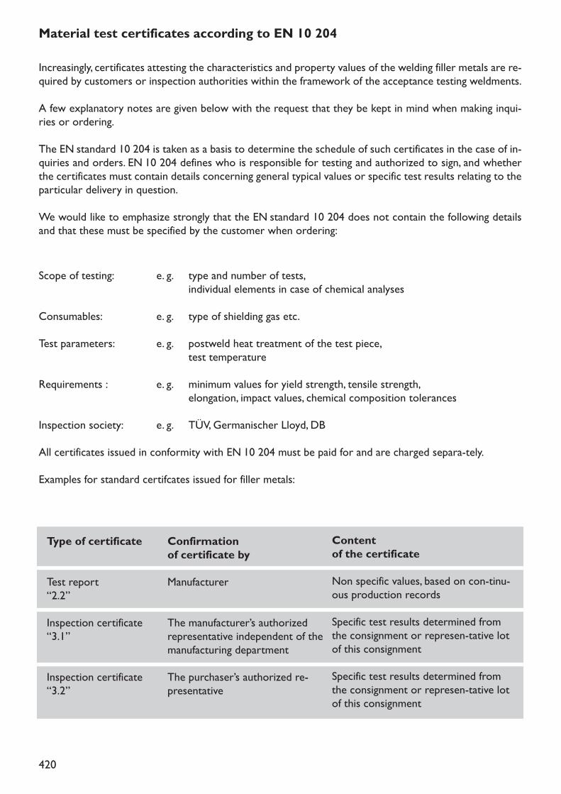
420
Increasingly, certificates attesting the characteristics and property values of the welding filler metals are re-quired by customers or inspection authorities within the framework of the acceptance testing weldments.A few explanatory notes are given below with the request that they be kept in mind when making inqui-ries or ordering.The EN standard 10 204 is taken as a basis to determine the schedule of such certificates in the case of in-quiries and orders. EN 10 204 defines who is responsible for testing and authorized to sign, and whetherthe certificates must contain details concerning general typical values or specific test results relating to theparticular delivery in question.We would like to emphasize strongly that the EN standard 10 204 does not contain the following detailsand that these must be specified by the customer when ordering:
Scope of testing: e. g. type and number of tests,individual elements in case of chemical analyses
Consumables: e. g. type of shielding gas etc.Test parameters: e. g. postweld heat treatment of the test piece,
test temperatureRequirements : e. g. minimum values for yield strength, tensile strength,
elongation, impact values, chemical composition tolerancesInspection society: e. g. TÜV, Germanischer Lloyd, DBAll certificates issued in conformity with EN 10 204 must be paid for and are charged separa-tely.Examples for standard certifcates issued for filler metals:
Type of certificate
Test report “2.2”Inspection certificate“3.1”
Inspection certificate“3.2”
Confirmationof certificate byManufacturer
The manufacturer’s authorizedrepresentative independent of themanufacturing departmentThe purchaser’s authorized re-presentative
Contentof the certificateNon specific values, based on con-tinu-ous production recordsSpecific test results determined fromthe consignment or represen-tative lotof this consignmentSpecific test results determined fromthe consignment or represen-tative lotof this consignment
Material test certificates according to EN 10 204
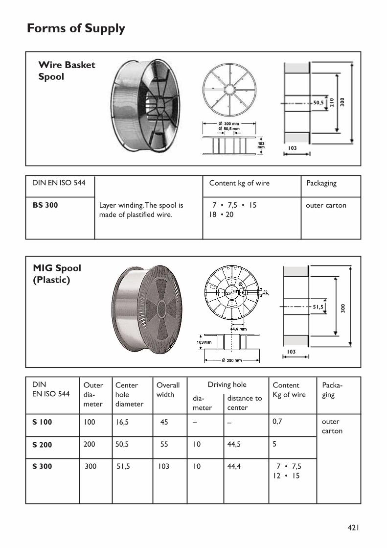
421
Forms of Supply
Layer winding. The spool ismade of plastified wire.
BS 300 17 • 7,5 • 15 18 • 20
outer carton
Wire BasketSpool
Content kg of wireDIN EN ISO 544 Packaging
MIG Spool(Plastic)
103
210 30050,5
10330051,5
17 • 7,512 • 15
Outerdia-meter
S 100
S 200
100 16,5 145 –
200 50,5 155 10
–
44,5
S 300 300 51,5 103
outercarton
0,7
5
10 44,4
Centerholediameter
Overallwidth
Driving holedia-meter
distance tocenter
Content Kg of wire
Packa-ging
DIN EN ISO 544
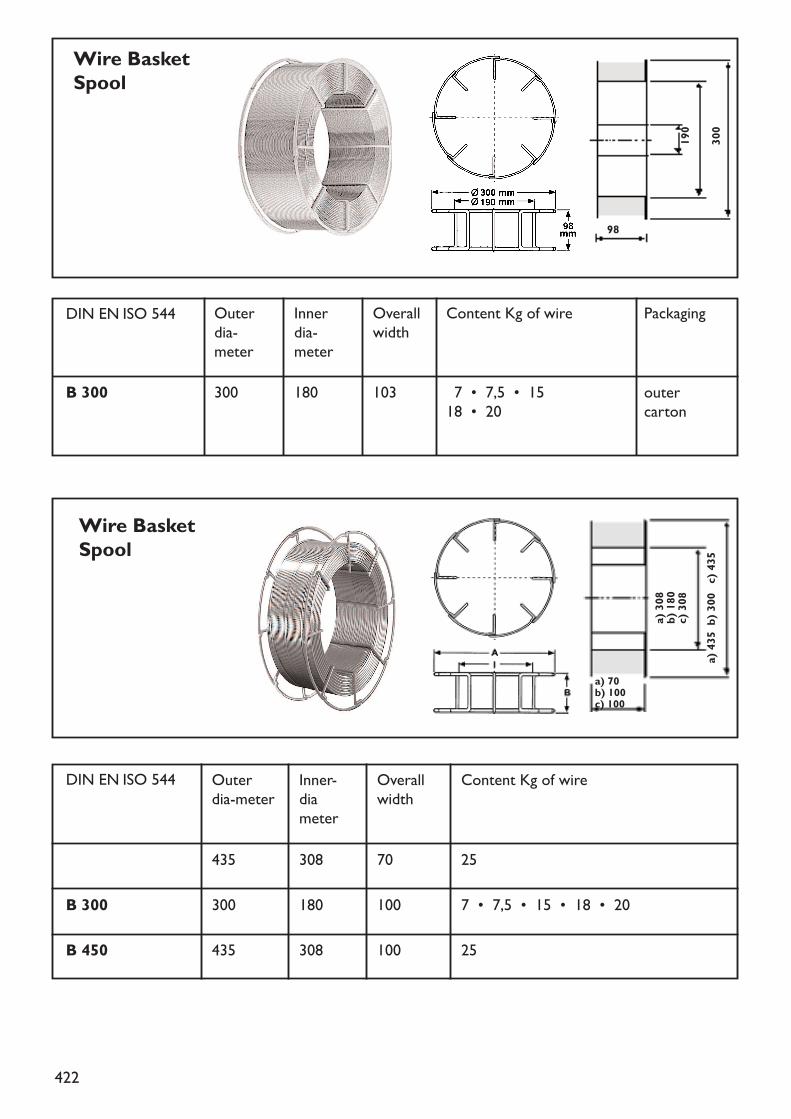
422
Wire BasketSpool
Wire BasketSpool
98
a) 70b) 100c) 100300190
a) 308
b) 180
c) 308
a) 435 b) 300 c) 435
Outerdia-meter
B 300 300 180 103 outer carton
Innerdia-meter
Overallwidth
Content Kg of wire Packaging
17 • 7,5 • 1518 • 20
DIN EN ISO 544
Outerdia-meter
B 300435 308 70
300 180 100
25
B 450 435 308 100 25
7 • 7,5 • 15 • 18 • 20
Inner-diameter
Overallwidth
Content Kg of wireDIN EN ISO 544
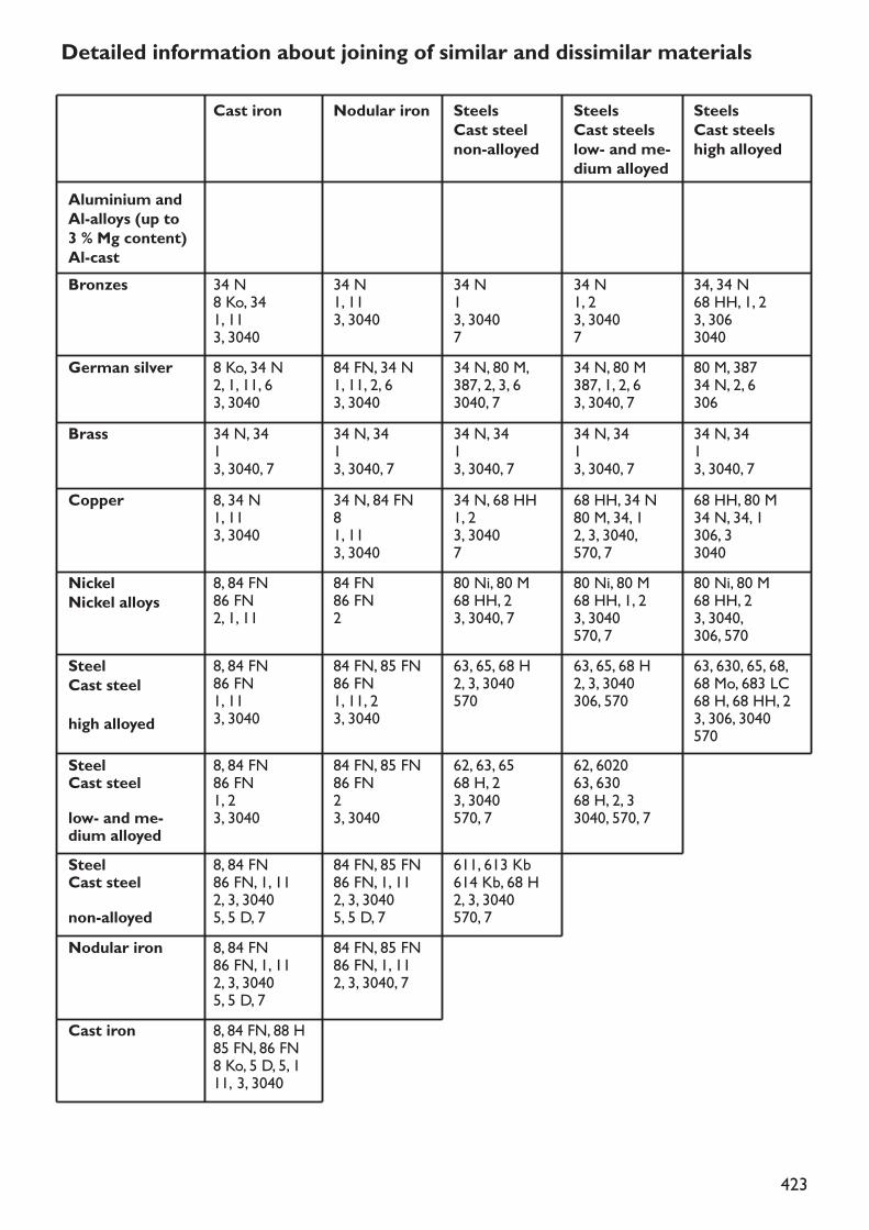
423
Detailed information about joining of similar and dissimilar materials
Aluminium andAl-alloys (up to3 % Mg content)Al-castBronzes 34 N
8 Ko, 341, 113, 3040
34 N1, 113, 3040
34 N13, 30407
34 N1, 23, 30407
34, 34 N68 HH, 1, 23, 3063040
German silver 8 Ko, 34 N2, 1, 11, 63, 3040
84 FN, 34 N1, 11, 2, 63, 3040
34 N, 80 M,387, 2, 3, 63040, 7
34 N, 80 M387, 1, 2, 63, 3040, 7
80 M, 38734 N, 2, 6306
Brass 34 N, 3413, 3040, 7
34 N, 3413, 3040, 7
34 N, 3413, 3040, 7
34 N, 3413, 3040, 7
34 N, 3413, 3040, 7
Copper 8, 34 N1, 113, 3040
34 N, 84 FN81, 113, 3040
34 N, 68 HH1, 23, 30407
68 HH, 34 N80 M, 34, 12, 3, 3040, 570, 7
68 HH, 80 M34 N, 34, 1306, 33040
NickelNickel alloys
8, 84 FN 86 FN2, 1, 11
84 FN86 FN2
80 Ni, 80 M68 HH, 23, 3040, 7
80 Ni, 80 M68 HH, 1, 23, 3040570, 7
80 Ni, 80 M68 HH, 23, 3040,306, 570
SteelCast steelhigh alloyed
8, 84 FN 86 FN1, 113, 3040
84 FN, 85 FN86 FN1, 11, 23, 3040
63, 65, 68 H2, 3, 3040570
63, 65, 68 H2, 3, 3040306, 570
SteelCast steellow- and me-dium alloyed
8, 84 FN 86 FN1, 23, 3040
84 FN, 85 FN86 FN23, 3040
62, 63, 6568 H, 23, 3040570, 7
SteelCast steelnon-alloyed
8, 84 FN 86 FN, 1, 112, 3, 30405, 5 D, 7
84 FN, 85 FN86 FN, 1, 112, 3, 30405, 5 D, 7
Nodular iron 8, 84 FN 86 FN, 1, 112, 3, 30405, 5 D, 7
Cast iron 8, 84 FN, 88 H85 FN, 86 FN8 Ko, 5 D, 5, 111, 3, 3040
84 FN, 85 FN86 FN, 1, 112, 3, 3040, 7
611, 613 Kb614 Kb, 68 H2, 3, 3040570, 7
62, 602063, 63068 H, 2, 33040, 570, 7
63, 630, 65, 68, 68 Mo, 683 LC68 H, 68 HH, 23, 306, 3040570
Cast iron Nodular iron SteelsCast steelnon-alloyed
SteelsCast steelslow- and me-dium alloyed
SteelsCast steelshigh alloyed
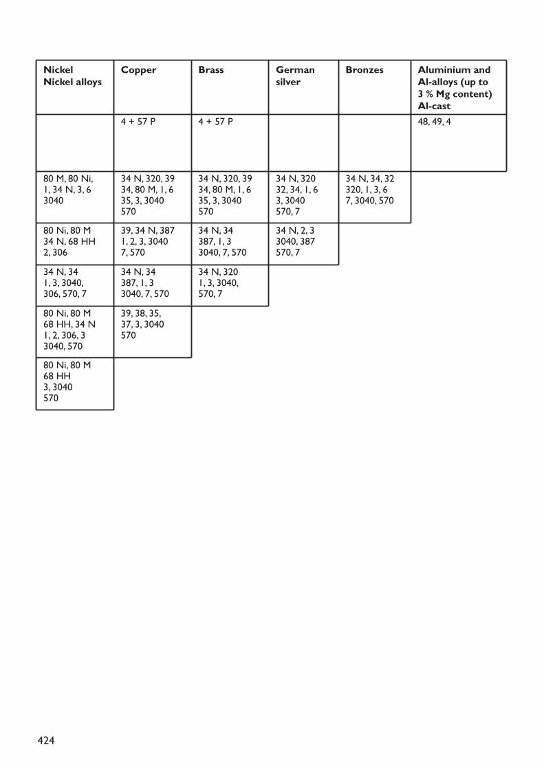
424
80 M, 80 Ni,1, 34 N, 3, 63040
34 N, 320, 3934, 80 M, 1, 635, 3, 3040570
34 N, 320, 3934, 80 M, 1, 635, 3, 3040570
34 N, 320 32, 34, 1, 6 3, 3040570, 734 N, 2, 33040, 387570, 7
34 N, 34, 32320, 1, 3, 67, 3040, 570
80 Ni, 80 M34 N, 68 HH2, 306
39, 34 N, 3871, 2, 3, 30407, 570
34 N, 34387, 1, 33040, 7, 570
4 + 57 P 4 + 57 P 48, 49, 4
34 N, 341, 3, 3040, 306, 570, 7
34 N, 34387, 1, 33040, 7, 570
34 N, 3201, 3, 3040, 570, 7
80 Ni, 80 M68 HH, 34 N1, 2, 306, 33040, 570
39, 38, 35,37, 3, 3040570
80 Ni, 80 M68 HH3, 3040570
NickelNickel alloys
Copper Brass Germansilver
Bronzes Aluminium andAl-alloys (up to3 % Mg content)Al-cast
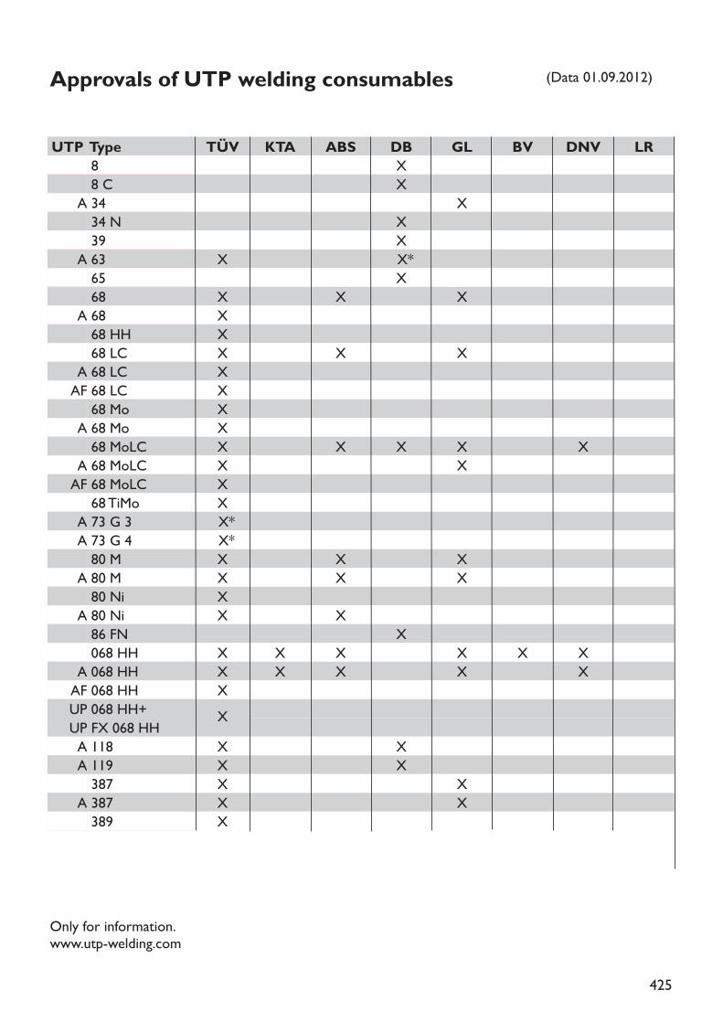
425
Approvals of UTP welding consumables
TÜV KTA ABS DB GL BV DNV LRXX
XXX
X X*X
X X XXXX X XXXXXX X X X XX XXXX*X*X X XX X XXX X
XX X X X X XX X X X XXXX XX XX XX XX
UTP Type88 C
A 3434 N39
A 63 6568
A 6868 HH68 LC
A 68 LCAF 68 LC68 Mo
A 68 Mo68 MoLC
A 68 MoLCAF 68 MoLC68 TiMo
A 73 G 3A 73 G 480 M
A 80 M80 Ni
A 80 Ni86 FN068 HH
A 068 HHAF 068 HHUP 068 HH+UP FX 068 HHA 118A 119387
A 387389
(Data 01.09.2012)
Only for information.www.utp-welding.com
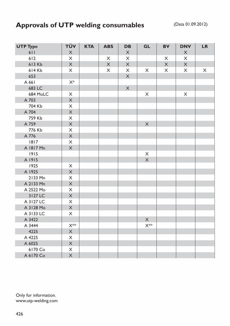
426
Approvals of UTP welding consumables
TÜV KTA ABS DB GL BV DNV LRX X XX X X X XX X X X XX X X X X X X
XX*
XX X XXXXXX XXXXX
XX
XXXXXXXXX
XX** X**XXXXX
UTPType611612613 Kb614 Kb653
A 661683 LC684 MoLC
A 703704 Kb
A 704759 Kb
A 759776 Kb
A 7761817
A 1817 Mn1915
A 19151925
A 19252133 Mn
A 2133 MnA 2522 Mo3127 LC
A 3127 LCA 3128 MoA 3133 LCA 3422A 34444225
A 4225A 60256170 Co
A 6170 Co
(Data 01.09.2012)
Only for information.www.utp-welding.com
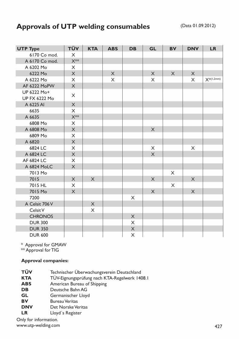
427
Approvals of UTP welding consumables
TÜV KTA ABS DB GL BV DNV LRXX**XX X X X XX X X X X*(1,2mm)XXXXX**XX XXXX X XX XXX
XX X X XX XX X X
XXX
XXXX
UTP Type6170 Co mod.
A 6170 Co mod.A 6202 Mo 6222 Mo
A 6222 MoAF 6222 MoPWUP 6222 Mo+UP FX 6222 MoA 6225 Al6635
A 66356808 Mo
A 6808 Mo6809 Mo
A 68206824 LC
A 6824 LCAF 6824 LCA 6824 MoLC7013 Mo70157015 HL7015 Mo7200
A Celsit 706 VCelsit VCHRONOSDUR 300DUR 350DUR 600
(Data 01.09.2012)
Approval companies:TÜV Technischer Überwachungsverein DeutschlandKTA TÜV-Eignungsprüfung nach KTA-Regelwerk 1408.1ABS American Bureau of ShippingDB Deutsche Bahn AGGL Germanischer LloydBV Bureau VeritasDNV Det Norske VeritasLR Lloyd´s Register
Only for information.www.utp-welding.com
* Approval for GMAW** Approval for TIG
428
All data on our products contained in this welding guide are based upon careful investi-gation and intensive research. However, we do not assume any liability for their correctness.
We recommend the user to test - on his own responsibility - our products with regard to theirspecial application.
Edition: September 2012

429
www.utp-welding.com


![[Files.indowebster.com] Welding Handbook](https://static.fdocuments.in/doc/165x107/55cf9c5b550346d033a99087/filesindowebstercom-welding-handbook.jpg)