Utilizing Artificial Intelligence to Achieve a Robust ... · Utilizing Artificial Intelligence to...
14
Utilizing Artificial Intelligence to Achieve a Robust Architecture for Future Robotic Spacecraft Steffen Jaekel German Aerospace Center (DLR) Robotics and Mechatronics Center Wessling, 82334 +49 8153 28 3496 [email protected] Abstract-This paper presents a novel failure-tolerant architecture for future robotic spacecraſt. It is based on the Time and Space Partitioning (TSP) principle as well as a combination of Artificial Intelligence (AI) and traditional concepts for system failure detection, isolation and recovery (FDIR). Contrary to classic payload that is separated from the platform, robotic devices attached onto a satellite become an integral part of the spacecraft itself. Hence, the robot needs to be integrated into the overall satellite FDIR concept in order to prevent fatal damage upon hardware or soſtware failure. In addition, complex dexterous manipulators as required for on- orbit servicing (OOS) tasks may reach unexpected failure states, where classic FDIR methods reach the edge of their capabilities with respect to successfully detecting and resolving them. Combining, and partly replacing traditional methods with flexible AI approaches aims to yield a control environment that features increased robustness, safety and reliability for space robots. The developed architecture is based on a modular on-board operational framework that features deterministic partition scheduling, an OS abstraction layer and a middleware for standardized inter-component and external communication. The supervisor (SUV) concept is utilized for exception and health management as well as deterministic system control and error management. In addition, a Kohonen self-organizing map (SOM) approach was implemented yielding a real-time robot sensor confidence analysis and failure detection. The SOM features non- supervized training given a typical set of defined world states. By compiling a set of reviewable three-dimensional maps, alternative strategies in case of a failure can be found, increasing operational robustness. As demonstrator, a satellite simulator was set up featuring a client satellite that is to be captured by a servicing satellite with a 7-DoF dexterous manipulator. The avionics and robot control were integrated on an embedded, space-qualified Airbus e.Cube on-board computer. The experiments showed that the integration of SOM for robot failure detection positively complemented the capabilities of traditional FDIR methods. T ABLE OF CONTENTS 1. INTRODUCTION ................................................. 1 2. STATE OF THE ART ••••••••••••••••••••••••••••••••••••••••••• 2 3. ON-BoARD OPERATIONAL ARCHITECTURE ••• .4 4. ARTIFICIAL INTELLIGENCE ARCHITECTURE •• 5 5. DEMONSTRATION SCENARIO •••••••••••••••••••••••••••• 8 6. CONCLUSIONS AND FUTURE WORK •••••••••••••••• 10 REFERENCES ••••••••••••••••••••••••••••••••••••••••••••••••••••••• 12 BIOGRAPHY •.•.•.•.•.•.•.•.•.•.•.•.•.•.•.•.•.•.•.•.•.•.•.•.•.•.•.•. 14 978-1-4799-1622-1/15/$31.00 ©2015 IEEE Bastian Scholz German Aerospace Center (DLR) Robotics and Mechatronics Center Wessling, 82334 +49 8153 28 1309 [email protected] 1. INTRODUCTION Cuently, the operation and rther development of robotic systems in space is an important topic as there is a multitude of applications. Using the Shuttle and Space Station Robotic Manipulator System (SRMS, SSRMS), respectively, the Inteational Space Station (ISS) was assembled from several modules using in-space robotic assembly (ISRA) [ 1 ]. Small robotic satellites are planned to serve for inspection purposes [2] and NASA's Robonaut [3] or comparable systems such as DLR's humanoid robot Justin [4] are candidates for ture EVA support operations. Similar to ISRA and EVA support, dexterous robotic manipulators are planned to be utilized to capture, maintain and/or de-orbit operational and defective satellites within on-orbit servicing (OOS) missions [5]. Finally, robotic exploration of other celestial bodies, such as the Moon, Mars or Near Earth Objects (NEOs) is already underway, and continues to be an important mission in space [6]. By introducing dexterous manipulators to traditional satellite platfos, the spacecraſt design becomes increasingly sophisticated and complex. Due to the high level of interdependencies between the manipulator and its floating base, it becomes an integral part of the overall spacecraſt design. Basically the whole satellite tus in into a 'space robot'. Consequently, the underlying computing environment needs to support both traditional satellite as well as robot control. In this context, a novel on-board architecture was presented within [7] that applies the concept of time and space partitioning (TSP) [8] on an embedded platform, provides configurable means for inteal and exteal communication for both real-time and non-real-time applications, as well as mechanisms for achieving autonomy and a system-level approach to failure management. In addition to the nominal conol environment, advanced capabilities in fault detection and diagnosis are an important problem in spacecraſt operations and a critical aspect of on- board soſtware with respect to safety, performance and reliability. Especially for on-orbit servicing spacecraſt, ground operators have to observe increasingly large volumes of telemetry for operation and fault diagnosis, especially if close-proximity operations including robotic manipulation are involved. The operator is not able to perceive all relevant environmental parameters and act
Transcript of Utilizing Artificial Intelligence to Achieve a Robust ... · Utilizing Artificial Intelligence to...

Utilizing Artificial Intelligence to Achieve a Robust Architecture for Future Robotic Spacecraft
Steffen Jaekel German Aerospace
Center (DLR) Robotics and
Mechatronics Center Wessling, 82334
+49 8153 28 3496 [email protected]
Abstract-This paper presents a novel failure-tolerant
architecture for future robotic spacecraft. It is based on the
Time and Space Partitioning (TSP) principle as well as a
combination of Artificial Intelligence (AI) and traditional
concepts for system failure detection, isolation and recovery
(FDIR). Contrary to classic payload that is separated from the
platform, robotic devices attached onto a satellite become an
integral part of the spacecraft itself. Hence, the robot needs to
be integrated into the overall satellite FDIR concept in order to
prevent fatal damage upon hardware or software failure. In
addition, complex dexterous manipulators as required for on
orbit servicing (OOS) tasks may reach unexpected failure
states, where classic FDIR methods reach the edge of their
capabilities with respect to successfully detecting and resolving
them. Combining, and partly replacing traditional methods
with flexible AI approaches aims to yield a control
environment that features increased robustness, safety and
reliability for space robots. The developed architecture is
based on a modular on-board operational framework that
features deterministic partition scheduling, an OS abstraction
layer and a middleware for standardized inter-component and
external communication. The supervisor (SUV) concept is
utilized for exception and health management as well as
deterministic system control and error management. In
addition, a Kohonen self-organizing map (SOM) approach was
implemented yielding a real-time robot sensor confidence
analysis and failure detection. The SOM features non
supervized training given a typical set of defined world states.
By compiling a set of reviewable three-dimensional maps,
alternative strategies in case of a failure can be found,
increasing operational robustness. As demonstrator, a satellite
simulator was set up featuring a client satellite that is to be
captured by a servicing satellite with a 7-DoF dexterous
manipulator. The avionics and robot control were integrated
on an embedded, space-qualified Airbus e.Cube on-board
computer. The experiments showed that the integration of
SOM for robot failure detection positively complemented the
capabilities of traditional FDIR methods.
T ABLE OF CONTENTS
1. INTRODUCTION ................................................. 1
2. STATE OF THE ART ••••••••••••••••••••••••••••••••••••••••••• 2
3. ON-BoARD OPERATIONAL ARCHITECTURE ••• .4
4. ARTIFICIAL INTELLIGENCE ARCHITECTURE • • 5
5. DEMONSTRATION SCENARIO •••••••••••••••••••••••••••• 8 6. CONCLUSIONS AND FUTURE WORK •••••••••••••••• 10
REFERENCES ••••••••••••••••••••••••••••••••••••••••••••••••••••••• 12
BIOGRAPHY •.•.•.•.•.•.•.•.•.•.•.•.•.•.•.•.•.•.•.•.•.•.•.•.•.•.•.•. 14
978-1-4799-1622-1/15/$31.00 ©20 15 IEEE
Bastian Scholz German Aerospace
Center (DLR) Robotics and
Mechatronics Center Wessling, 82334
+49 8153 28 1309 [email protected]
1. INTRODUCTION
Currently, the operation and further development of robotic systems in space is an important topic as there is a multitude of applications. Using the Shuttle and Space Station Robotic Manipulator System (SRMS, SSRMS), respectively, the International Space Station (ISS) was assembled from several modules using in-space robotic assembly (ISRA) [ 1 ]. Small robotic satellites are planned to serve for inspection purposes [2] and NASA's Robonaut [3] or comparable systems such as DLR's humanoid robot Justin [4] are candidates for future EVA support operations. Similar to ISRA and EVA support, dexterous robotic manipulators are planned to be utilized to capture, maintain and/or de-orbit operational and defective satellites within on-orbit servicing (OOS) missions [5]. Finally, robotic exploration of other celestial bodies, such as the Moon, Mars or Near Earth Objects (NEOs) is already underway, and continues to be an important mission in space [6].
By introducing dexterous manipulators to traditional satellite platforms, the spacecraft design becomes increasingly sophisticated and complex. Due to the high level of interdependencies between the manipulator and its floating base, it becomes an integral part of the overall spacecraft design. Basically the whole satellite turns in into a 'space robot'. Consequently, the underlying computing environment needs to support both traditional satellite as well as robot control. In this context, a novel on-board architecture was presented within [7] that applies the concept of time and space partitioning (TSP) [8] on an embedded platform, provides configurable means for internal and external communication for both real-time and non-real-time applications, as well as mechanisms for achieving autonomy and a system-level approach to failure management.
In addition to the nominal control environment, advanced capabilities in fault detection and diagnosis are an important problem in spacecraft operations and a critical aspect of onboard software with respect to safety, performance and reliability. Especially for on-orbit servicing spacecraft, ground operators have to observe increasingly large volumes of telemetry for operation and fault diagnosis, especially if close-proximity operations including robotic manipulation are involved. The operator is not able to perceive all relevant environmental parameters and act
accordingly in a timely manner. In the case of interplanetary probes, increased time delay further complicates the situation. Dissimilar to complex robotic systems the ground has, there is no emergency button in space to halt the current operation. Even after stopping the current movement, e.g. due to an internal robot failure, remaining drift of the freefloating base can still lead to a collision, potentially endangering the mission success. Thus, autonomous nominal operation capability as well as FDIR functionality must be transferred from the ground to the spacecraft itself in order to cope with these challenges. In addition, such capability results in a significant reduction of operational cost and increase in operational uptime, as the spacecraft does not remain in safe mode after unresolvable failure until a respective recovery routine is triggered by ground personnel.
For traditional satellites such as Earth observation or telecommunication spacecraft, conventional and wellestablished FDIR methods have been shown to reduce the occurrence of safe mode events and thus, increase the spacecraft's operational time. One significant drawback of classical fault diagnosis, however, is that it depends on predefined error patterns, i.e. specific values or ranges of a set of variables. These are subsequently connected to a failure recovery routine represented by a set of actions. Furthermore, recovery routines are usually executed in open-loop, meaning that the resulting system state after each execution are not necessarily congruent with the expected state.
Combining and partly replacing classic methods with flexible AI approaches that are able to detect previously unknown failure states aims to yield a control environment that features increased robustness, safety and reliability for space robots The developed framework presented in this paper aims to cope with these challenges by complementing traditional system FDIR with an AI approach for robot failure detection with special focus on the operation of onorbit servicing robotic spacecraft.
2. ST A TE OF THE ART
Time and Space Partitioning
The modular architecture presented in this paper consists of multiple software components running on a single on-board computer. In order to achieve spatial partitioning for both error containment through separation and re-usability through independent software verification processes, they are separated in logical containers, i.e. partitions. In addition, temporal partitioning through scheduling facilitates a deterministic system behavior [9, 1 0].
The described principle has already been adopted in some industry branches. The aeronautic industry introduced a comparable principle with the Integrated Modular Avionics (lMA) [ 1 1 ] and the ARINC 653 [ 12] specifications. The automotive industry currently tries to establish AUTOSAR
978-1-4799-1622-1115/$31.00 ©2015 IEEE 2
in order to decrease the number of hardware control elements built into the car [ 1 3]. Time and space partitioning concepts in space are still in their early stage [9]. ESA, in cooperation with space industry [8], and NASA, are particularly interested in applying this technology in the next generation spacecraft [ 14].
FDIR in Space
Within the field of FDIR, a fault can be defined as an undesired deviation of the property of some system variable from an acceptable or nominal behavior that potentially leads to degraded overall system performance, malfunctions, up to loss of the mission itself [ 1 5]. In this context, a FDIR mechanism is composed of the following tasks [ 1 6] :
Detection of the presence of a fault and its rate of occurrence (D) Determination of its location, type as well as estimation of its severity (I) Reconfiguration of the faulty element and/or overall spacecraft in order to achieve nominal system behavior (R)
Failures are typically classified by their criticality and the level on which they occur in the control system, which also correlates to the present level to autonomy. Low-level equipment failures can be resolved locally, or, if not recoverable from, are propagated to the next higher level up to system control level. This layered structure comprises a hierarchically distributed FDIR system with the aim to resolve occurring failures on the lowest possible level. The higher the failure is propagated, the more system knowledge and thus, deliberative capabilities are required by the FDIR architecture to autonomously identify, isolate and successfully resolve the problem. [ 17]
Traditional FDIR concepts are able to react to predefmed events and subsequently select a recovery routine from a given set of options accordingly [ 18]. Failure recognition is mainly based on fixed thresholds, logical conjunctions of variables, device built-in health and consistency checks that trigger the switch of redundant software and/or hardware components up to complete strings of hardware and software. In addition, analytical redundancy is utilized that is based on voting mechanisms or estimation techniques such as Kalman filters. These correlations are mostly implemented at design time and are based on extensive evaluation using the engineering methods of failure mode, effects and criticality analysis (FMECA) as well as failure tree analysis (FTA) [1 9]. In addition to hard-coded reactions, the use of on-board control procedures (OBCP) allows script-like actions that are assembled of telecommands, e.g. using the Packet Utilization Standard (PUS), or specific language implementations [20]. This allows in-flight adaption of the failure management logic through the upload of new OBCPs. As ultimate system reaction to unresolvable failures, the spacecraft is transitioning into safe mode, from where it has to be

...
::c Q � o
e> ... ... .. �..c = ... ti° �
Analytical model
based FDIR
Remote Agent on Deep
Space One, 1998 [24]
Fault diagnosis in (GNC),
2010 [31]
Bayesian
Networks
Fault diagnosis in SSHM, 2011 [33]
Autonomous SIC FDLR,
2012 [19]
Landing Site Selection,
Artificial Neural
Networks
Advanced FDIR (ESA), 2001 [28]
Fuzzy
Logic
SMARTJDLR, 2003 [36]
Landing Site Selection,
2009 [37]
1 '--__ 2 _00_6""'[3_4..:... ] __ -' AOCS subsystem control,
Dempster-Shafer
Evidence Theory
Landing Site Selection,
2009 [41]
Fault diagnosis in SSHM, 2010 [29]
------------------,------------------- r ------------------T 2010�� r-------------------· MEX thruster FDl, 20 I 0 I
Fault Diagnosis in Power I
Sensor FDIR with NN, I :===========::::: I
[32] Subsystems, 2009 [35] 1991 [26]
Rocket engine FDl, 1990 [25]
Fault diagnosis in reaction
wheels, 2011 [39]
FaLLIt diagnosis in Power
Subsystem, 1996 [40] I I I I ------------------;-------------------- . - . - . - ·1-------------------,.,-------------------·
FDIR for actuator faults in Robust robotic I FDI for cooperative a robot arm, 1999 [44] manipulation, 2008 [30] • manipulators, 2008 [27]
Collision preventing for
ERA 2006 [45]
FDl for robot
manipulators, 2008 [42]
. I
;"'._._._.J D Theoretical I
Simulation D Flown
r- • , I . Field of . _ . I Research
Figure 1: Overview of research in the artificial intelligence (AI) domain for FDIR in space
recovered from by ground control. the sensors in the Space Shuttle Main Engine (SSME) [25],
The established FDIR principles as outlined above constitute a good level of robustness for trad itional satellites are industrially mastered and established within the development process [2 1 ]. However, they have limited or no knowledge of the actual on-board operational capabilities. Mostly they only allow partial observability of the overall system which leads to shortcomings in autonomous isolation and recovery capabilities. One prominent example is Mars Express [22]. Due to non-resolvable memory failure it suffered from repeated safe mode transitions, as a result six months of operation time was lost.
In order to extend the operational on-board capabilities of FDIR systems, several studies have been conducted utilizing methods of artificial intelligence (AI) as summarized in Figure 1 . The research can be classified into analytical models, Bayesian reasoning, artificial neural networks (ANN), fuzzy logic and the Dempster-Shafer evidence theory [23]. A significant step towards a more robust and autonomous on-board system and the only actual in-flight study in this domain was the remote agent experiment aboard Deep Space 1 [24], The agent was capable of taking certain decisions autonomously, based on model knowledge and thus, to react to unpredicted behavior without additional human interaction. Other studies addressed the evaluation of previously defined analytical rules describing specific parts of the system in order to detect irregularities or deviations. In 1 990, one of the first approaches was made in this area using analytical failure detection and isolation methods for
978-1-4799-1622-1115/$31.00 ©2015 IEEE 3
This method was later enhanced by introducing an ANN in order to estimate the actual value of the faulty sensor [26]. The ANN representing the dependencies between the temperature sensors was trained during the startup of the SSME allowing it to memorize the thermal behavior. Subsequently, the network was able to detect anomalies and recover from them by sensor estimation without the need to shut down the engine. The previously discussed methods all address the level of subsystem or actuator FDIR. In [27], a Bayesian network was successfully used in order to describe the spatial relationships between the different parts of a 6-DoF robotic manipulator, which was used in order to detect failures such as blocked or deformed joints.
In addition to the model-based approaches described above, other studies tried to use more 'advanced' soft computing techniques, e.g. the ' Advanced FDIR' study of the European Space Agency (ESA) [28], In this work, different methods for system FDIR were addressed such as Bayesian networks, which are able to deal with corrupt or missing values using previously defined dependencies in the system. Furthermore, configuration spaces allow the system to recover from a detected failure by estimating the erroneous value by a comparison of the healthy part with a fault-free model of the system. Within [29], the Dempster-Shafer Evidence Theory was applied on fault diagnosis in software and sensor health management (SSHM). This theory uses a combination of uncertain information resulting in a belief function, which describes the probability of failure for different values. Although there are many different

techniques and studies using and evaluating advanced FDIR methods, only the remote agent experiment was actually flown and tested in space, whereas all the other projects remain theoretical simulations including a few specific onground hardware tests. The projects [27] and [3 1 ] were applied to manipulators on ground. The proposed principle, however, could be transferred to the space domain.
The work described within this paper investigates the capabilities of neural networks for manipulator sensor failure detection. One advantage of ANN's is that they are capable of adapting to changed properties of the system or the environment. They show a robust behavior if the input differs from the expected and trained input space and are capable of dealing with high noise or uncertainties in a value. This robust model behavior together with estimation capabilities of faulty sensors makes neural networks a promising candidate for reliable robot failure detection.
3. ON-BOARD OPERATIONAL ARCHITECTURE
On-Board Framework and Components
The developed on-board framework is composed of several layers and software components that together form the functionality for a holistic control approach for both classic satellite operations and robotic control. Figure 2 depicts the basic composition of the embedded architecture. For achieving spatial and temporal separation, each node or computational unit runs a TSP operating system (OS) such as VxWorks 653 or PikeOS. Available resources are separated into partitions, where usually one component is dedicated to one partition in order to achieve complete separation for safety purposes and to ease the deterministic scheduling configuration. Hardware equipment such as a GPS unit or arbitrary sensors and external communication interfaces, are each represented by a specific equipment handler component that exclusively has access to the equipment's resources and can share its status and data with other components.
The framework contains a middleware that provides a standardization of on-board communication through an abstract interface definition as well as an OS abstraction layer for cross-platform portability. At this point, the OS abstraction layer has been implemented for Linux (nonTSP), VxWorks 6.9 (non-TSP), and PikeOS. In addition to the abstraction layer and middleware services, the core components provide system control functionality of a classical spacecraft, cpo Figure 3. The supervisor (SUV) is used for deterministic system control and fault management. It is the only component with administrative system access and can therefore observe, start and stop all other components. The 110 Handler (lOH) implements the external operator interface using the packet utilization standard (PUS) [40] as a de-facto-standard in the European space industry and provides routing functionality between multiple nodes and spacecraft. The configurable data management (DM) realizes a data centric approach, i.e. all
978-1-4799-1622-1115/$31.00 ©2015 IEEE 4
Node
Partition 1 Parlilion2
[] [] Component1 Component2
[] Co�onent3
I Middleware & OSAI. I l J lOS I II
I Figure 2: On-board framework composition
components can store and read data from/to the DM. Through configuration of the DM, thresholds and other parameter statistics that are automatically evaluated can be defmed. Similar to traditional FDIR functionality, upon threshold violation a system event can be thrown. The event handler (EVH) collects these asynchronous exceptions or notifications and distributes them according to its configuration. By triggering event-connected actions within components (callbacks) or script-like on-board control procedures that are handled by the OBCP handler (OBCPH), an event/action mechanism is realized on which autonomous functionality can be built. The mission time line handler (MTH) contains the mission timeline (MTL) that is composed of time-tagged commands. The logging handler (LOH) records all occurring system events, actions and configured data for subsequent transmission to ground. Through their configurability, all core components and established equipment handlers for specific external interfaces can be re-used over mUltiple missions without changing their code, saving implementation and verification resources. In addition, mission components e.g. specific robotic control (ROB) components and/or a mission planner (MPL) broaden the capabilities of the on-board system. The MPL is currently implemented as a functional interface that can trigger offline-built task plans and store them in the MTL, the contained commands are subsequently executed upon time-tag expiration. Additional to its core functionality, the SUV may contain mission specific code, e.g. simple pre-defined failure management logic.
Communication Interfaces
Impedance control concepts allow a responsive or compliant manipulation of targets through haptic feedback. They require sufficiently high-speed and real-time data links with low jitter in the communication channel in order to keep the control system stable. In addition, the manipulator movement imposes a direct physical feedback on its floating base. Thus, synchronous data from other subsystems, e.g. the AOCS is required for actively stabilizing the platform or ignoring this external disturbance. Within the framework, inter-component communication is achieved by message

Core Components
ilJ ilJ ilJ MTH::MTLHandler EVH:: OM::
EventHandler Data Management
ilJ ilJ ilJ LOH:: OBCPH:: GenericConponem
LoggingHandler OBCPHandier IOH::IOHandler
SUV:: superviso� I I
Application Components
ilJ ilJ ilJ EQH:: MPL:: ROB::
EquipmentHandler MissionPlanner RoboticControl
Figure 3: Core and specific software components
queues for asynchronous and synchronous system level communication and shared memory for synchronous high performance real-time communication. With the IOH, the framework features its own PUS implementation for transparent communication both from space-to-ground, between spacecraft as well as on-board between different nodes. PUS messages are decoded, mapped to internal component callbacks and subsequently forwarded to the dedicated receiving component. This process is transparent to the software components. Classic housekeeping (HK) is implemented by the DM. The operator can subscribe to single parameters and/or groups that are subsequently sent to ground in the configured manner via the dedicated HK service. In general, arbitrary PUS services can be mapped to internal framework callback functions of components that implement the required functionality of the service.
Failure Management and Autonomy
The framework design follows the common three tier (3T) architecture for system autonomy, cpo Figure 4. By combining the data-centric approach of the data management (low level synchronous and asynchronous parameter control layer), the event/action mechanism (asynchronous low-level reaction and exception handling), scheduling (sequencing level with the mission time line) and task planning (deliberative layer) together with system supervision and control realized by the supervisor, a high degree of system autonomy can be achieved. The supervisor concept is used for both function and health monitoring. By
3T layers
1. Deliberative Layer
2. Sequencing Layer
3. Reactive Layer
Corresponding main service classes
Planning (MPL)
M New V plan
MTH
Pre· I condition Action
sense
M New V action
1]' Re·plan
I Postcondition
lr Action W finished
Action (SUV, STK EQH . . . )
Figure 4: Three Tier architecture for autonomy
978-1-4799-1622-1115/$31.00 ©2015 IEEE 5
utilizing the spatial partitioning principle, the continuation of the mission can be assured even on critical component failure. As part of the health management, partitions can be restarted by the supervisor after an unresolvable failure was detected, in case this measure is applicable to the ongoing spacecraft operations. The SUV also starts, controls, e.g. mode management, and shuts down the system and its components in a deterministic order. With these methods, a holistic and deterministic system-level failure detection, isolation and recovery (FDIR) scheme can be configured.
Due to this configurability of the modular system together with knowledge about the health status of each component, the SUV as central instance obtains a high degree of overall system knowledge. Consequently, also model-based FDIR decisions based on the current system task and available resources can be included, resulting in a higher flexibility and fault tolerance compared to traditional one-to-one mapping between cause and action.
A more detailed description of the frameworks composition and functionality can be found in [7]. The architecture comprises a variety of methods for achieving both traditional event/action and model-based autonomy for nominal operations and failure handling. The next chapter describes an additional AI approach for robot sensor failure detection to complement the before mentioned system-level methods.
4. ARTIFICIAL INTELLIGENCE ARCHITECTURE
Artificial Intelligence (AI) is used to solve a wide variety of problems in different domains. For robotic manipulators, AI can enable the control system to learn and react to unknown and/or unpredictable events and inputs resulting in higher robustness of the control system. The presented approach focuses on artificial neural networks (ANN) and a further development of ANN, the self-organizing map (SOM). Currently the most common use of SOMs is forecasting, classification and pattern recognition [43]. For humanmachine interfaces, SOMs are used for speech recognition to handle and interpret a spoken input. Here the exact structure of such input is not known, as there is a multitude of different voices and dialects and the words are spoken fluently, possibly without clear distinction [46]. Furthermore, those maps are used to get a clear representation of survey results that include multidimensional information. The information is transferred into a human-readable two dimensional map. Those ANNs or SOMs are characterized by a black box-like behavior, meaning that some input generates a specific output with the help of previously trained dependencies, which are generated automatically without human interaction. One of the advantages of such a network is that it does not require detailed knowledge of the described system since all the required data is fed into the black-box during training. Due to this process the network adapts its inner connections, called weights, and therefore is able to express the properties in a net-like structure. During real

Joint 1 [deg] Joint 2 [deg] Joint 3 [deg] Joint 4 [deg] Joint5[deg] Joint 6 [deg] Joint 7 [deg]
200 190 180 170
Tep Pos X Em) Tep Pos Y [m] Tep Pos Z [m] Tep Orient X [deg] Tep Orient Y [deg] Tep Orient Z [deg]
o Training Sets 200 Training Sets 1000 Training Sets
80
�60 Q) g> 40 « c: '0 20 --,
0 100
100 Y[-I 50
o 0 o 0
0
Q) C> c « c: '0 --,
100
50 X [-I Y [-I
o 0
100
50 X [-I
Figure 5: Trained SOM with all 13 vector elements displayed in a distinct plot (top) and example for different stages
of the training process for one information in the map (bottom)
time operations the SOM can deal with both expected (trained) and unexpected inputs, Returning feasible outputs in both cases makes this approach reliable and robust. [47]
Artificial Neural Networks
An ANN consists of one input layer, one or more hidden layers and one output layer, which are usually multidimensional. They contain a variable amount of nodes, dependent on the complexity of the system to be approximated. All of them are connected by weights represented by a normalized value between 0 and 1 , which is tuned during training or even in the running system to be able to adapt to changes in real-time. If an input vector is fed into the ANN it is processed from node to node beginning at the input layer through the hidden layer until an output is returned at the end node. In this process the initial input values are recalculated in each node according to their weights. ANNs can be trained to represent basic mathematical functions, such as sine and cosine, but also more complex and partially unknown dependencies, e.g. as given with the temperature sensors in a Space Shuttle Main Engine (SSME) [26].
Self-Organizing Maps
In this paper, a subgroup of ANN is used, the SOM, which is similar to an ANN with one output and one hidden layer
978-1-4799-1622-1115/$31.00 ©2015 IEEE 6
represented by a two-dimensional arrangement of weights as depicted in Figure 5. Here, x and y-axes describe the position in the map, whereas the z-axis shows the nonnormalized value of the weight. The SOM can be characterized as a two-dimensional discretized representation of a high dimensional input space. These maps are trained using non-supervised learning, which means they recognize the pattern and dependencies of the input space and store them equally [43].
Figure 6 depicts a schematic overview of the OOS system with the coordinate frames of the servicer, client, arm end effector (tool center point, TCP) and base camera as well as the grasp frame. Both the arm and the servicer base camera see the client to be captured, and can estimate the relative position and orientation of the grasp frame yielding the two transformations Tcaml-grasp and Tcam2-grasp. In addition, the current arm configuration provides the transformation Tcaml-cam2. As redundant information used for sensor validation, the position of the end effector represented by Tcaml-grasp r Icam2_grasp through camera estimation and Tcaml-cam2 through the robotic arm are evaluated by the SOM. This results in a 1 3-dimensional input space represented by the seven joint angles of the robot and the six-dimensional pose of the arms TCP. The 1 3-dimensional input is mapped onto two dimensions represented by the x and y-axes of the selforganizing map. Therefore each unit in the map contains 1 3 weights.

Architecture
The developed SOM framework is divided into two parts: the training process of the map and the actual operation of the system. The training can be done either on orbit, or on ground with simulated models, as long as the utilized model is accurate. The resulting map is subsequently used to determine the confidence of the input and recover the correct value of a corrupt sensor if necessary.
Training o/the SOM
The training algorithm generates a consistent map in order to enable a fast and robust determination of a joints confidence. Starting with a randomly initialized map the weights of each unit are adapted gradually until neighboring units are similar in their weights, cpo Figure 5 (bottom). After initializing the SOM with 1 3 random, but consistent, values within reasonable limits determined by the work space of the manipulator, the actual training process begins. The flow chart depicted in Figure 7 illustrates the conducted steps. For this purpose several hundred data sets of joint angles and corresponding TCP poses were gained from either fault-free operation of the robotic arm or a simulated model. The data sets are divided into two groups, one used for training, the other for post-training evaluation. Therefore the training process is split into epochs of 100 training sets in order to evaluate the current status of the map after each epoch. This is done by choosing random data out of the evaluation sets and feeding it into the SOM. As soon as the error between its output and the expected result goes below a specific threshold, the SOM has completed the training process. In order to further improve the performance of the AI-system and limit the size of the maps, the operational range of each joint is adapted to the expected workspace by the planned approach trajectory. The range for each of the seven joints is subsequently split into two parts resulting in
a total of 27 = 128 maps, increasing the overall resolution
while keeping the size of each map constant. In contrast to one large map containing the same information, the matching process becomes significantly faster. The procedure of adapting the randomly initialized SOMs to the input space is done step by step. One training set at a time is chosen randomly and is fed into the SOM. According to the joint angles in this set, one map out of the pool of 128 maps containing the specific joint configuration is chosen and trained. The training function searches for the best matching unit (BMU) in the respective map and adjusts the weights of the unit as well as its direct neighbors.
Neighborhood size
The amount of neighbors being adapted is determined by a variable, which is decreased with time. In the beginning this value has to be big in order to get a rough shape of the input space in a short time, but is decreased until only one unit is changed towards the end of the training procedure to obtain the required map precision. The algorithm uses the formula
978-1-4799-1622-1115/$31.00 ©2015 IEEE 7
CglObal
Figure 6: Schematic overview of the OOS mission with
the servicer satellite on the left and the client satellite to
be capture on the right.
nSlzei = nSlzeo x exp -i x 0 x Kn , . . ( IOg(nSiZe ) )
#settrain ( 1 )
with Kn being proportional to the desired speed of training and i the current iteration of sets. The higher the speed of training with higher Kn, the faster the adapt ion of the map to the given training space. However the precision will be worse, since the last sets to be trained still have an influence on a big area of the map, which means that the system loses its memory; older sets are overwritten by newer ones. Furthermore the influence of the total amount of training sets #seurain in ( 1 ) guarantees, that at the end of the training procedure only a few units are adapted, whereas in the beginning for i = 0
nSize#settrain = nSizeo (2)
units will be changed. This results in a fast change of the map in the early stage of training, leading from quick change to precise fine-tuning towards the end of the process. The training yields similar precision for a constant (but small) neighborhood size, with the disadvantage of taking much more time compared with the previously described procedure. In this particular case the best experience was
made with Kn = 2 and a neighborhood size starting at nSize_O = 0.25 * map Dim depended on the size of the map.
Learning Rate
Be�ide the neighborhood size, the learning rate (LR) plays an unportant role in the training of a SOM. It describes how much one unit is changed during the iterations and decreases exponentially with ongoing training sets:
Divide sets Acquire data sets from ___ � fault free system
maps
Adapt weights
Make unit consistent
Figure 7: SOM training process
(. 10g(LRo) 1 ) LRi = LRo exp L x x .
#settrain KLR x epoch with LRo E ]0; 1[.
(3)
Again a faster change in the map can be achieved with an
increase of K LR' The difference to ( 1 ) is the dependency on the epoch, which is currently being trained. The longer the training is in progress, the better the map already adapted to the input space and the less it should be affected by changes in order to achieve the best precision possible. The number of training sets #set_train is reset to 0 after each epoch and starts to increment again with each iteration
Weights Update
Using the previously determined learning rate (3) and neighborhood size ( 1 ) the new weight of the currently treated unit is calculated by applying
Wnew = Wold X LR x (nSize - dist2BMU) x tow. (4)
The distance of the neighbors to the BMU affects the new weight, too. Starting directly at the center of the neighborhood the change in the weight is maximal, while decreasing towards the edge. This results in a smooth distribution in the map, which is necessary to achieve a fast processing during confidence calculation. Furthermore the difference between old unit and input vector (toweight) influences the magnitude of change as well. With (4) each unit in the map is adapted to the current training set until the evaluation sets indicate a satisfying level of precision.
Sensor Fault Detection and Lost Value Estimation
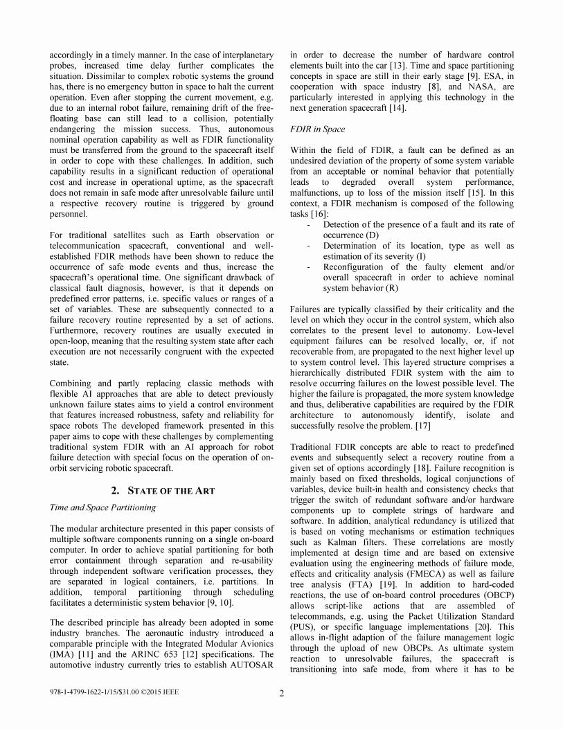
Figure 8 depicts the conducted steps for observing all joints continuously in the real-time environment based on the
Extract all values but one
joint angle
Use estimated 1-----1 angle
fully-trained and stored map. As previously discussed, the system consists of several maps covering different parts of the joint range. The algorithm for calculating the confidence for one joint uses all information but this specific value and identifies the best matching unit based on the remaining 12 weights within all relevant maps.
Determining the BMU in a map can be done in mUltiple ways. The method of brute force search allows the system to always fmd the best solution while losing performance with regard to time-behavior. In addition, the method of gradient descent is much faster with the risk of detecting a local minimum of the Euclidean distance between input space and the units in the map instead of the desired global minimum. Using five randomly distributed starting points for gradient descent and subsequently choosing the best result has been found to be a good compromise between precision and speed. A fmite impulse response (FIR) filter is applied to the found estimated angle over time to further improve the performance. Due to oscillation of the found solution around the true value due to local minima, the filter interpolates the estimated value and thus further increases the maps resolution.
The estimated joint angle is subsequently compared to the measured one. If the sensor is working properly, the estimated value should be near the measured one yielding a high sensor confidence, whereas a big difference indicates a sensor failure or blocked joint. By applying a thresholdtriggered event to the confidence, a respective recovery routine, e.g. retracting the arm, can be issued. Alternatively, the recovered joint angle can be used in the control scheme instead of the measured value to complete the current task.
Use measured �---il�;an; g; le��e-
________ -/
Figure 8: Sensor confidence estimation scheme
978-1-4799-1622-1115/$31.00 ©2015 IEEE 8

5. DEMONSTRATION SCENARIO
Demonstration Setup
The Gennan Orbital Servicing Mission (DEOS) [48] currently under development at DLR forms the basis for the OOS demonstrator presented in this paper. DEOS investigates technologies to autonomously and manually perform rendezvous and proximity operations, as well as to capture a tumbling and uncooperative target satellite with a dexterous manipulator based on DLR's 7-DoF Lightweight Robot III (L WR-III). As demonstrator, an on-orbit servicing scenario was set up with the Systems Tool Kit (STK) for visualization and for feeding realistic orbit and communication data into the data management via a designated equipment handler (STK _ EQH). In the scenario, a client satellite is to be captured autonomously by the servicing satellite that features a 7-DoF dexterous manipulator with a gripper. Figure 10 followed by Figure 9 depict the demonstrator architecture and the orbit simulation environment, respectively. The avionics and robot control is set up on an embedded, space-qualified e.Cube as relevant target platform. Within an earlier investigation, scenarios including successful robotic capture and the initiation of an arm emergency retract triggered by an unexpected loss of signal (LOS), were successfully perfonned [7]. This demonstrated the on-board system's capabilities to cope with autonomous nominal operations and failure management. The setup was extended by the presented selforganizing map architecture in order to complement the traditional FDIR mechanisms with advanced AI approaches. At the current stage, the AI framework is located outside the on board architecture for research purposes. However, after further developing the current solution, it is planned to integrate it into the framework. Based on the introduced AI functionality, experiments with sensor failure during arm operations have been conducted, including sensor outage and drift, both leading to emergency routines after the failure was discovered. In addition, nominal operations were continued using estimated sensor data after sensor failure
Figure 9: STK orbit simulation of OOS scenario
shortly before capture.
Path planning for all capture trajectories of the robotic arm was perfonned offline using a multi-body simulation tool [49] and subsequently included as pre-planned sequences in the mission planner. The escape trajectory for the arm retract maneuver is represented by the inverse motion of the approach. The realistic satellite simulation calculates orbit position, communication times (acquisition of signal, loss of signal) and lighting conditions and forwards them via UDP to the STK equipment handler, the data is subsequently stored in the data management. The on-board framework for the experiments comprises all essential core components, the data management (DM), event handler (EVH), 110 handler (lOH), mission timeline handler (MTH) and Supervisor (SUV). As specific components a robot control component (ROB_CTRL), equipment handler (ROB_EQH) and mission planner (MPL) are implemented.
On the operator side, a graphical interface for creating PUS commands (CmdGUI) and a tool that converts this input into binary PUS packets are used. The 10H receives these commands and routes them to the designated on-board component. In the scenario the SUV is commanded to initialize the complete on-board system and bring all
Figure 10: Deployment diagram of on-orbit servicing demonstrator setup
978-1-4799-1622-1115/$31.00 ©2015 IEEE 9
Satellite Simulation (Win) On-Board Framework (VxWorks embedded, Linux) Operator (Linux)
MATLAB/STK I/O Handler (IOH)Ev ent Handler (EVH)
Mission Timeline Handler (MTH)
STK Equipment Handler (STK_EQH)
Robot Control (ROB_CTRL)
Robot Equipment Handler (ROB_EQH)
Mission Planner (MPL)
CSV2PUS
CmdGUI
Superv isor (SUV)
Serv ice Interface (SIF)
Data Management (DM)
AI Framework (Win)
MATLAB Confidence Estimation
sensor confidence
csv
status
taskplan csv
rob ctrl
cmd
cmd
rob joints, cameraestimation
raiseevent
PUSrob ctrl
sats pose, AOS, LOS
data
rob ctrl
datacmd
cmd

Confidence and angle values for Joint 1 f�� U 60 L-----------------------------------------------------------1% �
150; ., � log
5 45 58
Confidence and angle values for Joint 3
� 1���-----------::::::� u 60 L-----------------------------------------------------------
� �
i" � '6
20 15'0) 0; ., ., 10 � � log ., g> i '"
-10 5 '5
-200 10 15 20 25 time[sl
Confidence and angle values for Joint 6
f�� U 60,L-----------------------------------------------------------
ro �
60
g;so '; h..-....-cO:::;::;O---� g40 '"
30
-70
C> Q) � Q) 0) -90 c ro
Confidence and angle values for Joint 2
f�� U 60 L-----------------------------------------------------------
20 60
�50 150; ., 0> � ., "0 10 9 "<;'40 0> i" c: � '" 30 5 '6
Confidence and angle values for Joint 5
f�� U 60 L-----------------------------------------------------------
� �
15 15'0) 0; ., ., 5 � � log ., g> -5 i '" 5 '6
Confidence and angle values for Joint 7 f�� U 60 L-----------------------------------------------------------
20 0 20
175 ! "<;, 150 0> c: '"
20
-11%���5 ���10�� --1� 5�---2�O---��25��--3�0 ��3� 4���40-=�--4� 5--=�
time [5] Figure 11: Joint angle trajectory for all 7 joints. The confidence (in magenta) with a horizontal line marking 80% threshold (upper part). The measured joint angle (blue) is depicted together with the estimated (red) and correct
(green) values. The difference between correct and estimated is colored in cyan with a separate scale.
978-[-4799-1622-1115/$31.00 ©20[5 IEEE 10

components into their required state. The SUY reads the STK and sensor confidence data from the data management and triggers the MPL upon AOS to plan and initiate the autonomous satellite capture maneuver. The plan is stored in the mission timeline and subsequently executed through the robot control component. For the control of a real robot, ROB CTRL would interface with the actual hardware via a robot equipment handler that implements the specific robot interface, e.g. EtherCA T or SERCOS. In the case of the demonstrator scenario, ROB _ EQH simply forwards its input to the STK _ EQH component which sends the planned joint values of the dexterous manipulator to the orbit simulation and the AI framework. AOS, LOS and confidence threshold violation events are triggered by the EQH _ STK and subsequently processed by the event handler. The SUY as configured receiver processes these events and acts accordingly. In the case of unexpected sensor outage or drift, the autonomous capture maneuver is aborted and an emergency arm retract maneuver is triggered. In another scenario, shortly before capture the faulty sensor is ignored and the estimated value forwarded to the robot control component.
Demonstration Results
Several pre-planned trajectories for the autonomous target capture were executed with the robot sensor confidence analysis in the loop. Table 1 summarizes the mean error and computation time for multiple options. While larger maps result in a higher accuracy with a mean error below 2.S degrees between estimated and true joint angle, the computational time increased accordingly. The best results were achieved using maps of the size of SOxSO together with the method of gradient descent and filtering. Interestingly, the mean error using gradient descent and filtering is smaller than the brute force variant, which is due to the interpolation effect realized by this combination. Although the AI computation does not comply with the real-time interval of the robot control, it yields a robust measure of the actuator sensor health that could be integrated into the control loop.
Table 1: Estimation error and processing time
Map size # of maps method mean mean compo error ['] time [ms]
brute force 4 .52 1263 50x50 128 - - - - - - - - - - - - - - - - - - - - - - - - - - - - - - - - - - - - - - -
grad . desc. 3 . 2 1 349
brute force 3 .05 4373 100xlOO 128 - - - - - - - - - - - - - - - - - - - - - - - - - - - - - - - - - - - - - -
grad . desc. 2 .46 872
During the capture scenarios, the following types of sensor fai lures have been investigated. In the case of a hard failure
the sensor stops working at a given time, returning only zero. This can be due to communication or electrical problems. A bias failure makes the sensor stuck at its current value, having a constant output after this time. Hardware or communication problems can cause this behavior. Temperature or calibration Issues can cause a
978-1-4799-1622-1115/$31.00 ©2015 IEEE 1 1
sensor drift, which adds a constant term to the output increasing in time. In the case an outlier failure occurs the sensor output jumps to a specific value in short peaks. This can be caused by a poor connection or other electrical problems. This failure is only a temporary problem, the sensor continues working properly afterwards.
Figure 1 1 depicts an exemplary plot with the joint angle trajectory for all seven joints of the manipulator. Several failures have been introduced in joint 4 during the approach maneuver. After I Ss, three successive peaks in the measured signal can be observed, representing a simulated outlier failure. Those are detected immediately as the confidence drops below the defined 80% threshold. Furthermore the estimated angle indicated in red is not influenced by these failures. A few seconds later starting at t\=24.Ss the joint experiences a drift failure resulting in a decrease of confidence, which is finally breaking the threshold 2.9s later at 12=27.4s. Similar to the peaks, the estimated angle is not affected, continuously following the correct value of the joint angle. The confidence of the remaining six joints was not affected. Further tests with realistic noise both in the camera estimation and the joint sensors lead to almost no loss in precision. The offline experiments and conducted scenarios showed that the SOM AI FDIR approach is a feasible and robust method for detecting robot sensor failures during autonomous maneuvers. Moreover, nominal operation could be continued based on estimated sensor values. Thus, temporary sensor fluctuation, outliers and peaks do not lead to an unnecessary abortion of the current operation, adding robustness to the space-robotic system. However, the computation time is still relatively high and has to be optimized in future implementations in order to minimize the reaction time of the system. The given amount of data for the chosen method results in approx. 30MB of memory space, which is a feasible requirement for modem on-board computers such as the Airbus e.Cube.
6. CONCLUSION AND FUTURE WORK
The presented architecture follows an integrated approach required for safely operating future robotic spacecraft where the satellite becomes a space robot. In addition to the robust and tested core framework, a combination of classic system FDIR and an advanced AI approach for robot failure detection were developed and successfully demonstrated. Together with the frameworks data-centric approach, event/action mechanisms, mission planning and scheduling, supervision and control, a high degree of mission autonomy and failure robustness could be achieved. The AI approach showed good robustness with respect to joint failure detection, even if significant sensor noise was present. Furthermore, estimated sensor values could be used as replacement for the faulty sensor to be fed into the robot control system, allowing continuous nominal operation if appropriate. A significant strength of the presented AI method is that it can also be trained during the mission. It is quite flexible and can be quickly adapted to different hardware properties. The demonstrator showed that the
architecture is a promising candidate for robotic on-orbit servicing spacecraft.
Further investigations should be made in order to improve the method in terms of precision and speed. For example, this can be achieved by adding further information from redundant sensors. After fully integrating the presented AI into the on-board framework, it should be further tested with a hardware-in-the-Ioop (HIL) system, e.g. DLR's DEOSSirn facility. Finally, by introducing artificial intelligence techniques with partly non-deterministic behavior in the space domain, the development of a suitable verification and validation process becomes a big challenge with respect to the current requirements in the space industry. In this context, it might be a future path to allow a specific but controlled degree of uncertainty and non-deterministic behavior while gaining a significant advance in autonomy capabilities and robustness, especially when it comes to the operation of complex space robotic systems.
7. ACKNOWLEDGEMENTS
Part of the presented research was funded by the Space Management of the German Aerospace Center (DLR) with federal funds from the Federal Ministry of Economics and Technology in accordance with the parliamentary resolution of the German Parliament (Grant No. 50RA I I I 0).
REFERENCES
[ 1 ] Mohan, S. and D.W. Miller, SPHERES Reconfigurable Framework and Control System Design for Autonomous Assembly, in AIAA Guidance, Navigation, and Control Conference. 2009: Chicago, USA.
[2] Stoll, E., Jaekel, S., Katz, J., Saenz-Otero, A. and Varatharajoo, R. (20 12), SPHERES interact-Humanmachine interaction aboard the International Space Station. J. Field Robotics, 29: 554-575. doi: 1 0. 1 002/rob.2 14 19
[3] Diftler MA, Ahlstrom TD, Ambrose RO, Radford NA, Joyce CA, De La Pena N, Noblitt AL. Robonaut 2 -Initial Activities On-Board the ISS. 20 12 IEEE Aerospace Conference, Big Sky, MT. 20 12 : pp. I - 12. DOl: 1 0. 1 1 09/AER0.20 12.6 187268.
[4] Zacharias, F and Leidner, D and Schmidt, F and Borst, C and Hirzinger, G (20 l O) Exploiting Structure in Two-armed Manipulation Tasks for Humanoid Robots. the IEEE International Conference on Intelligent Robots and Systems (lROS), Taipei, Taiwan.
[5] Hirzinger, G., et aI., DLR's robotics technologies for on-orbit servicing. Advanced Robotics, 2004. Special Issue Service Robots in Space: p. 1 39-1 74.
978-1-4799-1622-1115/$31.00 ©2015 IEEE 12
[6] Biesiadecki, J.J.; Maimone, M.W., "The Mars Exploration Rover surface mobility flight software driving ambition, " IEEE Aerospace Conference (2006), doi: 1 0. 1 1 09/AER0.2006. 1655723
[7] Jaekel, S. et aI., Robust and Modular On-Board Architecture for Future Robotic Spacecraft, Aerospace Conference, 20 14 IEEE, Big Sky, MT, USA (March 20 14)
[8] Windsor, J., Hjortnaes, K. : Time and space partitioning in spacecraft avionics. In: Proc. 3rd IEEE Int. Conf. on Space Mission Challenges for Information Technology (SMC-IT 2009). pp. 1 3 {20. Pasadena, CA, USA (Jul 2009)
[9] Rushby, J. : Partitioning in avionics architectures: Requirements, mechanisms and, assurance. NASA Contractor Report CR -1 999-20934 7, SRI International, California, USA (Jun 1 999)
[ 1 0] Seyer, R., Siemers, c . , Falsett, R., Ecker, K., Richter, H.: Robust partitioning for reliable real-time systems. In: Proc. 18th Int. Parallel and Distributed Processing Symp. pp. 1 1 7 { I22 (Apr 2004)
[ 1 1 ] Watkins, c . , Walter, R.: Transitioning from federated avionics architectures to Integrated Modular Avionics. In: Proc. 26th IEEE/AIAA Digital Avionics Systems Conf. (DASC 2007). Dallas, Texas, USA (2007)
[ 12] AEEC: Avionics application software standard interface, part 1 - required services. ARINC Specication 653PI -2 (2006). Part 2 - extended services. ARINC Specication 653P2-1 (2008)
[ 13] D. Kum et al : "AUTOSAR migration from eXlstmg automotive software, " International Conference on Control, Automation and Systems, ICCA (Oct. 2008)
[ 14] Hodson, R., Tak Ng, T. : Avionics for exploration. In: NASA Technology Exchange Conference, Galveston, TX, USA. (Nov 2007)
[ 1 5] Wander, T., Forstner, R., Innovative Fault Detection, Isolation and Recovery Strategies On-Board Spacecraft: State of the Art and Research Challenges, German Aerospace Congress (20 12)
[ 1 6] Henry, D., Sirnani, S. and Patton, R., Fault Detectionand Diagnosis for Aeronautic and Aerospace Missions, in Fault tolerant flight control: A benchmark challenge, Berlin: Springer Verlag, pp. 91-128 (20 l O)
[ 17] Morgan, P. S., Fault protection techniques in JPL Spacecraft, in Proceedings of the First International Forum on Integrated System Health Engineering and Management in Aerospace, ISHEM (2005)

[ 18] Olive, X., FDI(R) for satellites: How to deal with high availability and robustness in the space domain?, International Journal of Applied Mathematics and Computer Science, vol. 22, no. 1 , pp. 99-107 (20 12)
[ 19] Codetta-Raiteri, D. et aI., ARPHA: a software prototype for fault detection, identification and recovery in autonomous spacecrafts," Acta Futura, vol. 5, pp. 99-1 l O (20 12)
[20] Space engineering: Spacecraft on-board control procedures, ECSS-E-ST-70-0 1 C (20 l O)
[2 1 ] A. Zolghadri, "Advanced model-based FDIR techniques for aerospace systems: Today challenges and opportunities," Progress in Aerospace Sciences (20 12)
[22] Lakey, D. T. et aI., Multi-Mission End-to-End OBCP Configuration Control, 12th International Conference on Space Operations, SpaceOps (20 12)
[23] Shafer, G. : A Mathematical Theory of Evidence, Princeton University Press, Princeton, N.J ( 1 976)
[24] Muscettola, N., Nayak, P., Pell, B., Wiliams, B. : Remote Agent: to boldy go where no AI system has gone before. Artificial Intelligence, vol. l O3, no. 1 -2, pp. 5-47 ( 1998)
[25] Meyer, c . , Zakrajsek, J, : Rocket Engine Failure Detection Using System Identification Techniques. In: NASA Contractor Report ( 185259). Sverdrup Technology, Inc., Lewis Research Center Group, Brook Park, OH, USA (Jun 1990)
[26] Guo, T., Nurre, J. : Sensor Failure Detection and Recovery by Neural Networks, National Aeronautics and Space Administration, Lewis Research Center. Cleveland, OH, USA ( 1991 )
[27] Tinos, R., Terra, M.: A Fault Detection and Isolation System for Cooperative Manipulators. In: Revista Controle & AutomacoIVol. l 9 noAIOutubro (Nov, Dez 2008)
[28] Holsti, N., Paakko, M.: Towards Advanced FDIR Components. Space Systems Finland Ltd., Espoo, FIN
[29] Wu, Y., Ren, Z., Zeng, Z.: Fault diagnosis method based on D-S evidence theory. In: Prognostics and Health Management Conference: PHM ' 1 0 (20 1 0)
[30] Sturm, J., Plagemann, c . , Burgard, W.: Adaptive Body Scheme Models for Robust Robotic Manipulation. Albert-Ludwigs- University, Freiburg, Germany
978-1-4799-1622-1115/$31.00 ©2015 IEEE 1 3
[3 1 ] Falcoz, A., Henry, D., Zolghadri, A. : Robust Fault Diagnosis for Atmospheric Reentry Vehicles: A Case Study. Systems, Man and Cybernetics, Part A: Systems and Humans, IEEE Transactions on, vol. 40, no. 5, pp. 886-899 (20 1 0)
[32] Patton, R. J., Uppal, F. J., Simani, S., Polle, B. : Robust FDI applied to thruster faults of a satellite system. Control Engineering Practice, vol. 18, no.9, pp. 1 093-1 1 09 (20 1 0)
[33] Schumann, J., Mengshoel, 0 . , Mbaya, T.: Integrated Software and Sensor Health Management for Small Spacecraft. In: 4th lEE Int. Conf. on Space Mission Challenges for Information Technology. (20 1 1 )
[34] Serrano, N. : A Bayesian Framework for Landing Site Selection during Autonomous Spacecraft Descent. In: IEEE/RSJ: Int. Conf. on Intelligent Robots and Systems (2006)
[35] Ricks, B., Mengshoel, 0 . : Methods for Probabilistic Fault Diagnosis: Electrical Power System Case Study. Silicon Valley Campus, Paper 60 (2009)
[36] Guiotto, A., Martelli, A., Paccagnini, C.: SMARTFDIR: Use of Artificial Intelligence in the Implementation of a Satellite FDIR. In: Data Systems in Aerospace (2003)
[37] Ploen, S., Seraji, H., Kinney, c.: Determination of Spacecraft Landing Footprint for Safe Planetary Landing. Aerospace and Electronic Systems, IEEE Transactions on, vol. 45, no. 1 , pp. 3-16 (2009)
[38] Zotes, Z., Pen as, M.: Intelligent satellites control based on fuzzy logic in the Earth-Moon Libration point. In: Intelligent Systems and Knowledge Engineering (lSKE), 20 1 0 Int. Conf. on (20 1 0)
[39] Meskin, N., Khorasani, K. : Fault detection and isolation: Multi-vehicle unmanned systems. New York: Springer (20 1 1 )
[40] Cayrac, D., Dubois, D., Prade, H. : Handling uncertainty with possibility theory and fuzzy sets in a satellite fault diagnosis application: Fuzzy Systems. In: IEEE Transactions on, Fuzzy Systems, vol. 4, no. 3 , pp. 25 1-269 ( 1996)
[41 ] Seraji, H., Serrano, N. : A Multisensor Decision Fusion System for Terrain Safety Assessment. IEEE Transactions on, vol. 25, no. 1 , pp. 99-lO8 (2009)
[42] Reppa, V., Tzes, A. : Fault Detection based on Orthotopic Set Membership Identification for Robot Manipulators. In: Proc. 1 7th IFAC World Congress, The international Federation of Automatic Control (Jul 2008)

[43] Kohonen, T. : Self-Organizing Maps. Springer Series in Information Sciences, Vol. 30, Springer, Berlin, Heidelberg, New York, Third Extended Edition (200 1 )
[44] Shin, J-H., Lee, J-1.: Fault Detection and Robust Fault Recovery Control for Robot Manipulators with actuator Failures. In: Proc. IEEE Int. Conf. on Robotics & Automation, (May 1 999)
[45] Fusco, F., Gallerini, R.: European Robotic Arm: The Problem of Preventing Collisions.
[46] Eng, G.K. : Malay Speech Recognition using SelfOrganizing Map and Multilayer Perceptron. In: Proc of the Postgraduate Annual Research Seminar (2005)
[47] Vesanto, 1. : Clustering of the Self-Organizing Map. In: IEEE Transactions of Neural Networks, Vol. 1 1 (2000)
[48] Sellmaier, F. et aI., On-orbit Servicing Missions at DLRlGSOC, in 6 1 st International Astronautical Congress, Prague, Czech Republic (20 1 0)
[49] Lampariello, R., Hirzinger, G., "Generating Feasible Trajectories for Autonomous On-Orbit Grasping of Spinning Debris in a Useful Time", accepted IEEE/RSJ International Conference on Intelligent Robots and Systems 20 1 3 (IROS 13 ), Tokyo, Japan, November 20 13 .
BIOGRAPHY
Steffen Jaekel studied Mechanical
Engineering and Aerospace
Engineering at Technische Universitdt
Miinchen (TUM) and as a visiting
student at Massachusetts Institute of
Technology (MIT). He received his MS.
degree in 201 1 from TUM Within his
Ph. D research at the German Aerospace Center (DLR) he currently
works in the field of space robotics with special focus on on
orbit servicing (OOS), failure detection, isolation and
recovery (FDIR) techniques and robust embedded avionics
architectures. Currently, he is actively involved in in multiple projects supporting the German on-orbit servicing
mission DEOS.
Bastian Scholz studied Aerospace
Computer Science at Julius
Maximilians Universitdt Wiirzburg
(JMUW) and Luled Tekniska
Universitet (LTU). He received his
B.Sc. degree from JMUW in 2010 and
will continue his studies in order to achieve the degree of MSc. in 2015. He currently works in the field of
artificial intelligence focused on FDIR methods for space
robotics.
978-1-4799-1622-1115/$31.00 ©2015 IEEE 1 4