Utilization of Repetitive Surge Oscillograph (RSO)
27
1 Utilization of Repetitive Surge Oscillograph (RSO) in the Detection of Rotor Shorted-Turns in Large Turbine-Driven Generators Isidor “Izzy” Kerszenbaum, PhD, PE EIC Conference - June 2011
-
Upload
shastri2010 -
Category
Documents
-
view
109 -
download
2
Transcript of Utilization of Repetitive Surge Oscillograph (RSO)

1
Utilization of Repetitive Surge Oscillograph (RSO) in the Detection of Rotor Shorted-Turns in
Large Turbine-Driven Generators
Isidor “Izzy” Kerszenbaum, PhD, PE
EIC Conference - June 2011
2
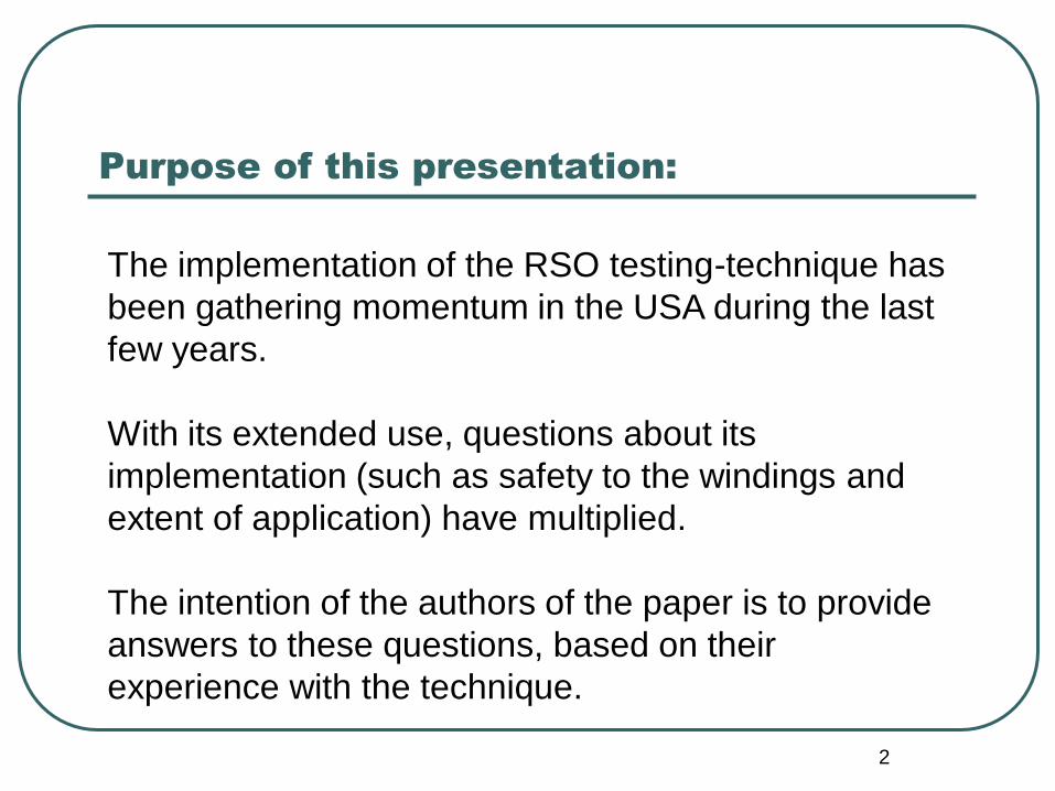
Purpose of this presentation:
The implementation of the RSO testing-technique has
been gathering momentum in the USA during the last
few years.
With its extended use, questions about its
implementation (such as safety to the windings and
extent of application) have multiplied.
The intention of the authors of the paper is to provide
answers to these questions, based on their
experience with the technique.

3
Typical cylindrical (turbo-generator) rotor
winding
SLOT AREA
OF THE
COIL
END-
WINDING
4
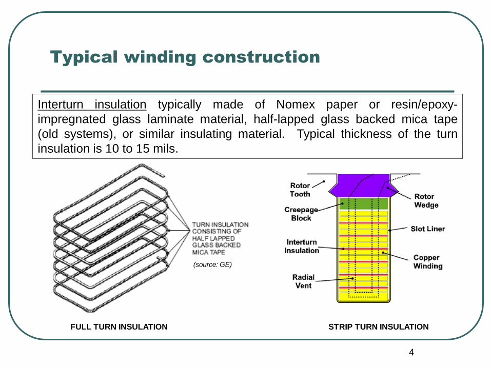
Typical winding construction
STRIP TURN INSULATION
(source: GE)
FULL TURN INSULATION
Interturn insulation typically made of Nomex paper or resin/epoxy-
impregnated glass laminate material, half-lapped glass backed mica tape
(old systems), or similar insulating material. Typical thickness of the turn
insulation is 10 to 15 mils.

5
Typical operating conditions
Temperatures of up to 155 C (class B rise).
Interturn voltages of several volts.
Strong mechanical pressure.
Tearing forces due to unequal elongation between copper, insulation.
Tearing forces due to relative movement during acceleration, deceleration, heating and cooling.
Vibration.

6
What’s a shorted turn?
In slot area In overhang area
Breach of insulation between
two (or more) adjacent turns in
the coil of a rotor winding.

7
Example of shorted
turns due to cyclic
loading of a generator
coupled with an
ineffective blocking of
the end-windings
8
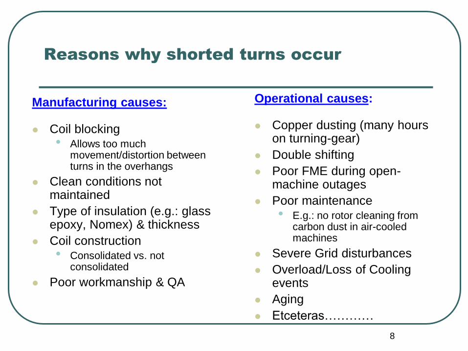
Reasons why shorted turns occur
Manufacturing causes:
Coil blocking • Allows too much
movement/distortion between turns in the overhangs
Clean conditions not maintained
Type of insulation (e.g.: glass epoxy, Nomex) & thickness
Coil construction • Consolidated vs. not
consolidated
Poor workmanship & QA
Operational causes:
Copper dusting (many hours on turning-gear)
Double shifting
Poor FME during open-machine outages
Poor maintenance • E.g.: no rotor cleaning from
carbon dust in air-cooled machines
Severe Grid disturbances
Overload/Loss of Cooling events
Aging
Etceteras…………
9
How do shorted-turns make themselves
noticeable?
Mostly by increased vibrations
Vibrations sensitive to field current (VAR) changes
Sometimes by reduced excitation capability
Often they DON’T cause any obvious performance changes and are only found by monitoring (e.g.: flux probe and shaft voltages) and/or by testing (RSO, Open Circuit voltage, impedance, pole-drop, etceteras)
10
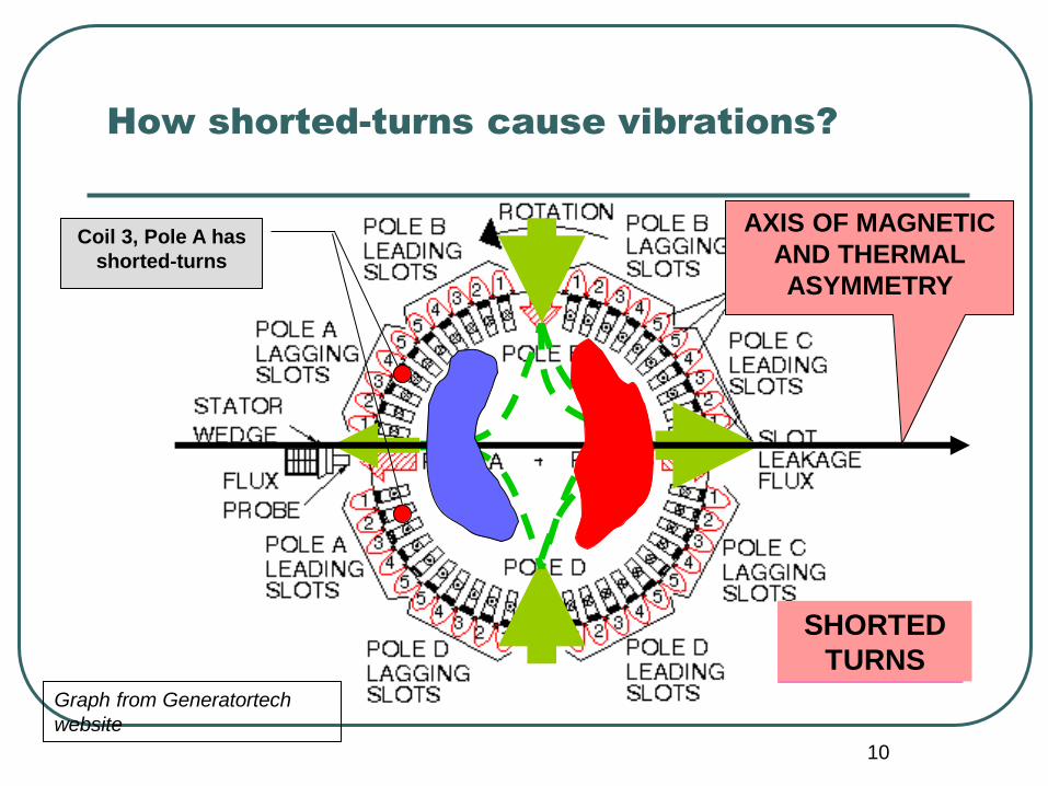
How shorted-turns cause vibrations?
Graph from Generatortech
website
NORMAL
CONDITION
AXIS OF MAGNETIC
AND THERMAL
ASYMMETRY
Coil 3, Pole A has
shorted-turns
SHORTED
TURNS

11
THERMAL ASYMMETRY
Fmagnetic B2/
MAGNETIC ASYMMETRY RESULT: VIBRATING ROTOR
Resulting bow and magnetic pull:

12
Where are shorted turns more prone to
occur?
R.H.S. L.H.S. Exciter End
Turbine End
Pole 1 Pole 4 Pole 3 Pole 2
SONGS UNIT 3 – OCTOBER 2004
13
How bad are shorted-turns?
Perhaps close to 50% of all units in operation have at least one shorted turn.
Some may remain stable (no additional shorts) for many years.
Some may continue to develop shorts and may eventually create a ground fault.
Some may have MANY shorts without any severe impact on operation.
Some may severely impact operation after only developing a few shorts.
Two-pole and four-pole units exhibit significant different behaviors due to shorted-turns.
Bottom Line: How bad it is and what needs to be done depends on the machine construction, history, OEM recommendations based on similar units’ history, Grid requirements, rating, age, etceteras.
14
What monitoring equipment and/or tests
are available for finding shorted-turns?
RFM (rotor flux monitor) – Requires unit on line and readings taken at various load points. Can be used to determine pole-coil location of the short.
Shaft-voltages – Requires unit running. Difficult interpretation of readings.
RSO (repetitive surge oscillosgraph or recurrent surge oscillogram) – Unit at rest or spinning without load and excitation removed.
O.C. Voltage Characteristics – Taken with unit at full speed and open breaker. Requires benchmark curve.
Rotor impedance vs. rpm.
“C-Core” test – Requires rotor out of bore.
Pole-Drop measurements – Rotor out. Maybe retaining rings off.

15
What is the RSO?
It is a testing technique used to detect shorted-turns by inserting a high-frequency, low-voltage waveform at both ends of the field winding, and visually evaluating the differences in the returning signals.
The RSO can be used with the rotor inside or outside the stator.
The RSO can be used while working on the rotor, due to the low voltage operation.
The RSO is safe to the interturn insulation due to its low voltage operation.
The RSO can ONLY be applied to cylindrical fields (turbo-generators), due to the inherent high symmetry of the winding.
16
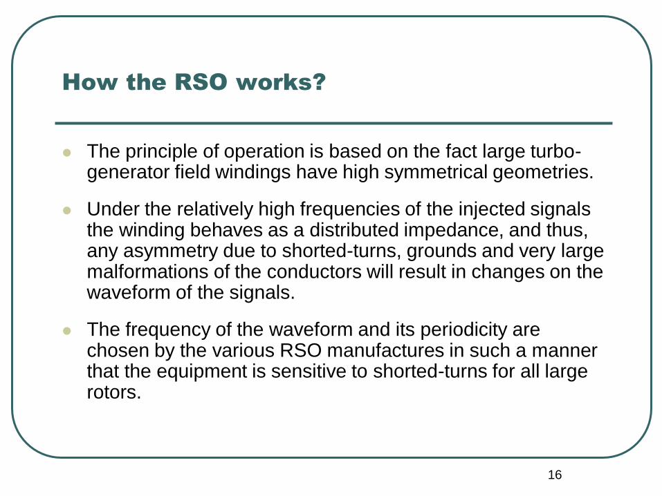
How the RSO works?
The principle of operation is based on the fact large turbo-generator field windings have high symmetrical geometries.
Under the relatively high frequencies of the injected signals the winding behaves as a distributed impedance, and thus, any asymmetry due to shorted-turns, grounds and very large malformations of the conductors will result in changes on the waveform of the signals.
The frequency of the waveform and its periodicity are chosen by the various RSO manufactures in such a manner that the equipment is sensitive to shorted-turns for all large rotors.

17
Typical circuit arrangement
RSO 110 Vac
Oscilloscope
Ground wire
Slip-rings For brushless machines, the
RSO wires are connected to
the ends of the field winding
after this is disconnected from
the diode wheel.

18
Basic design

19
Typical waveform of the signals generated
by the RSO
Typical rise-time: a few s
Typical voltage: 5-12 volts
V
CHANNEL A
CHANNEL B
TIME RISE TIME
SIGNAL
VOLTAGE
AMPLITUDE

20
Reading the signals
Although both resulting
signals can be compared, it
is easier to sum them up
after one channel is
inverted, and looking at the
resultant:
• Straight line: no shorts
• A distorted line: shorts are
present
(A Megger test is required
previous to the RSO test to
ascertain no grounds are
present in the winding)
21
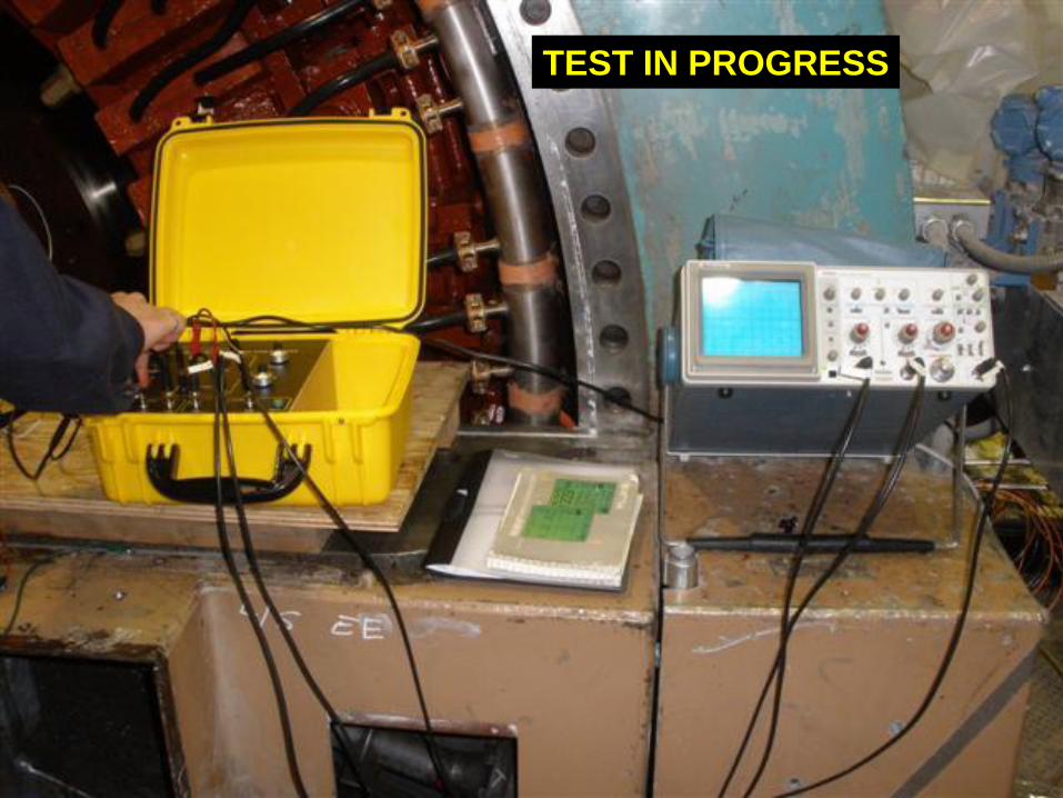
TEST IN PROGRESS

22
Real example
Channel A plus
inverted Channel B

23
Examples of real traces
NO SHORTS
ONE SHORT
ONE OR MORE SHORTS
SEVERAL SHORTS
With experience, depending on
the location of the “kinks” on the
line, rough localization of the
shorts (coil and pole) is
possible
24
Speed (pressure) dependency of shorted-
turns
A significant proportion of shorted-turns are pressure dependent. The pressure is a function of the position of the rotor when idle, or speed, when rotating.
Therefore, “spinning RSO” tests can be done with the unit at speed (during acceleration/deceleration and at full speed), to “catch” shorted turns that “disappear” when the rotor is standing still.
When the rotor is idle, RSO readings should be taken with the rotor rotated at several angles.

25
Typical arrangement for a spinning RSO
RSO Scope
Excitation
System
DC Leads Opened
Rotor Winding

26
Readings taken with the unit spinning
AT TURNING GEAR AT FULL SPEED

27
THANK YOU!!
QUESTIONS?


![minna atsumare 2019 (B) in rso LIFE GOES ON]€¦ · rso LIFE GOES ON] rso LIFE GOES 045-210-4961 FAX 045-210-8854 2019 10/20(B) rso LIFE GOES](https://static.fdocuments.in/doc/165x107/6002badcf232d942e9544e04/minna-atsumare-2019-b-in-rso-life-goes-on-rso-life-goes-on-rso-life-goes-045-210-4961.jpg)