Utility Needs of Power Conditioning Systems for PV and ... · Utility Needs of Power Conditioning...
36
1 FLORIDA SOLAR ENERGY CENTER Creating Energy Independence Since 1975 A Research Institute of the University of Central Florida Utility Needs of Power Conditioning Systems for PV and other Renewable DG A New Twist Bob Reedy +1.321.638.1470 [email protected]
Transcript of Utility Needs of Power Conditioning Systems for PV and ... · Utility Needs of Power Conditioning...

1
FLORIDA SOLAR ENERGY CENTER
Creating Energy Independence Since 1975
A Research Institute of the University of Central Florida
Utility Needs of Power Conditioning Systems for PV
and other Renewable DG
A New Twist
Bob Reedy+1.321.638.1470
2
“Green Power” ??
3
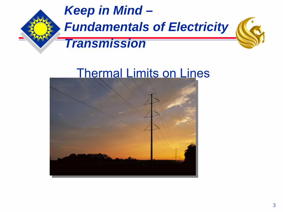
Keep in Mind – Fundamentals of Electricity Transmission
Thermal Limits on Lines

4
Keep in Mind – Fundamentals of Electricity Transmission
Power Transfer Limits

5
Keep in Mind – Fundamentals of Electricity Transmission
Voltage, Current, Frequency and Power
6
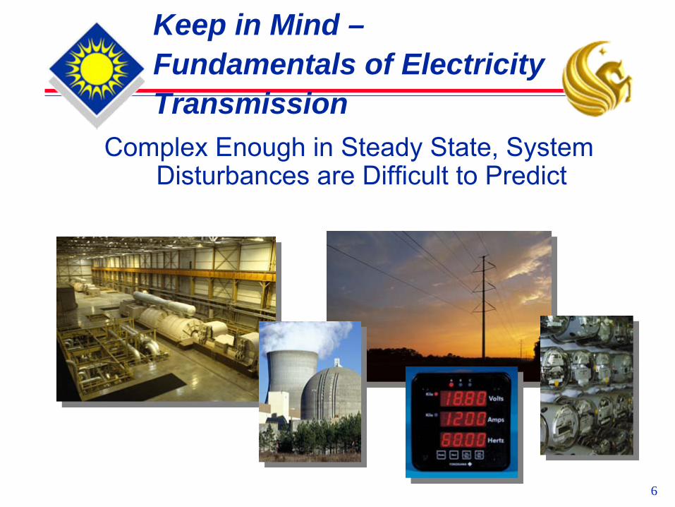
Keep in Mind – Fundamentals of Electricity Transmission
Complex Enough in Steady State, System Disturbances are Difficult to Predict

7
Keep in Mind – Fundamentals of Electricity Transmission
When Things “Trip”, it can get Crazy !

8
Keep in Mind – Fundamentals of Electricity Transmission
Generation must balance load in any area
=

9
The US Grid
Eastern Interconnect-- “the World’s Biggest Machine” 925,000,000 hp - 2,000,000 sq mi -- 3600rpm

10
Frequency ExcursionsEastern Interconnection Frequency
8-14-03
59.950
60.000
60.050
60.100
60.150
60.200
60.250
60.300
3:09:00 PM 3:10:00 PM 3:11:00 PM 3:12:00 PM 3:13:00 PM 3:14:00 PM 3:15:00 PM 3:16:00 PM
Time, CDT
Freq
uenc
y, H
z
DENA Bev. - Two second scan rate - 60.241 Hz.DENA Mas. - Two second scan rate - 60.257 Hz.SoCo Bhm. - Three second scan rate - 60.236 Hz.FPL - 0.1 Sec. fault recorder scan rate - 60.278 Hz.

11
By The Book
The Book : Applied Protective Relaying by Westinghouse Electric Corporation, Coral Springs, Florida, 1982The Basics :
Normally Σ Generation = Σ Loads + Σ LossesIf Σ Generation ≠ Σ Loads + Σ Losses then R = (pL(f1 – f0)/H(1-(f12/f02)) where :
R = average rate of change of frequency (Hz/sec)p = power factor rating of generators on system (assumed to be 0.85)L = average per unit overload = (Load – Generation)/GenerationH = Inertia constant for system, MW-s/MVA (assumed to be ≅ 4)f0 = initial frequencyf1 = final frequency
Note: Several of the following slides were “lifted”
(by permission) from a presentation by Raymond Vice and Bob Jones of Southern Co Svcs

12
ImplicationsRate of frequency change, R, depends:
The Load/Generation mismatchThe inertia of the system
Inertia of the system, H, is a factor of the inertia of the individual generators on the system :HSystem = (H1 *MVA1 + H2 *MVA2 + HN *MVAN )/(MVA1 + MVA2 + … + MVAN )
Mass & RPM determine machine HHydro generators tend to have a high inertia (≈ 10)Nuclear unit steam driven gen (4 pole)- relatively high inertia (≈ 5)Older steam turbine driven gen- relatively high inertia (≈ 4)Newer steam turbine driven gen- relatively low inertia (≈ 3)Combustion turbine gen--relatively high inertia (≈ 4 or 5)
13
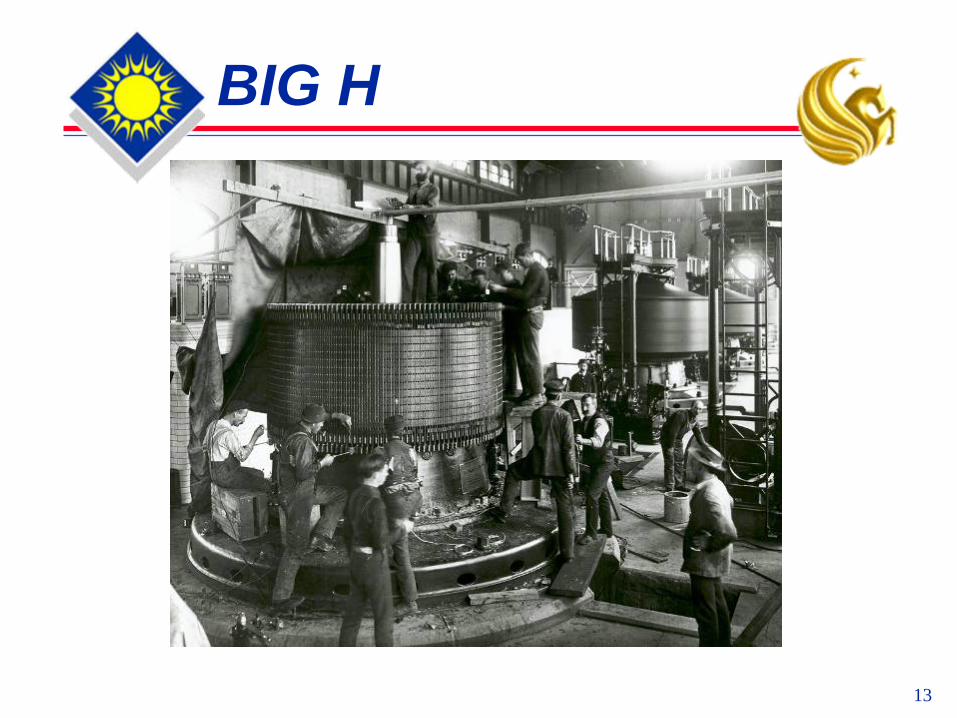
BIG H

14
System Stability
=

15
Frequency Excursions

16
Frequency Excursions

17
More Frequency Excursions
Near DISASTER !!The Greatest Oscillograph
Scoop of all time !
18
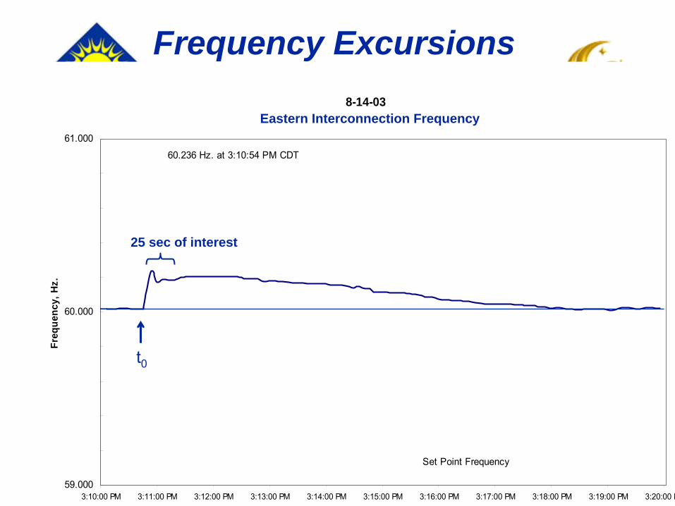
Frequency ExcursionsSouthern Control Area Frequency
8-14-03
59.000
59.200
59.400
59.600
59.800
60.000
60.200
60.400
60.600
60.800
61.000
3:10:00 PM 3:11:00 PM 3:12:00 PM 3:13:00 PM 3:14:00 PM 3:15:00 PM 3:16:00 PM 3:17:00 PM 3:18:00 PM 3:19:00 PM 3:20:00 P
Freq
uenc
y, H
z.
60.236 Hz. at 3:10:54 PM CDT
Set Point Frequency
Eastern Interconnection Frequency
t0
25 sec of interest

19
Something Really Scary !
Apparent & Approximate Envelope of the Undamped Oscillation, before System Reconfiguration (Islands) Led to a Damped Oscillation
Effective Breakup of the EI into Islands (largely due to operation of Zone 3 distance relays)
Eastern Interconnection Frequency8-14-03
t0
Note: Frequency of the Oscillation is about 1/3 Hz. This is the “Frequency of the Frequency”
Undamped Period Damped Period
20
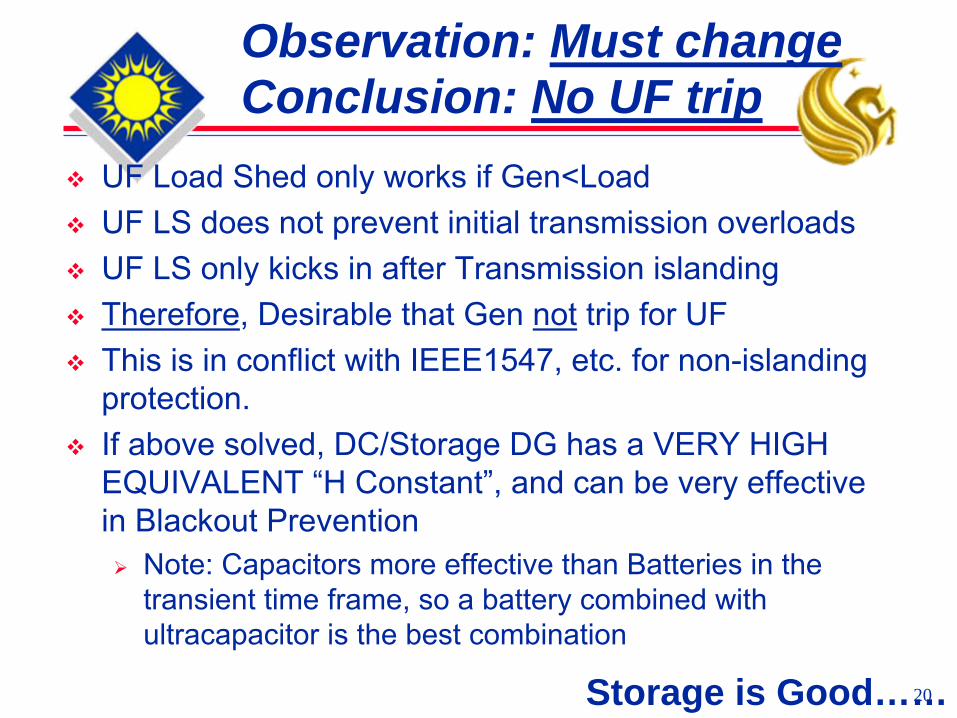
Observation: Must change Conclusion: No UF trip
UF Load Shed only works if Gen<LoadUF LS does not prevent initial transmission overloadsUF LS only kicks in after Transmission islandingTherefore, Desirable that Gen not trip for UFThis is in conflict with IEEE1547, etc. for non-islanding protection.If above solved, DC/Storage DG has a VERY HIGH EQUIVALENT “H Constant”, and can be very effective in Blackout Prevention
Note: Capacitors more effective than Batteries in the transient time frame, so a battery combined with ultracapacitor is the best combination
Storage is Good……

21
Southern Control AreaGenerator UF coordination curve
54
54.5
55
55.5
56
56.5
57
57.5
58
58.5
59
59.5
60
1 10 100 1000 10000
Time (Cycles)
Freq
uenc
y (H
z)
Trip Point per IEEE 1547
Trip Point of Turbines

22
Result:
Upset: Public Politicians Utilities

23
No Surprise:
Utilities/Suppliers/Politicians:seized on wrong solutions

24
Bogus Answers
BO of 03 led to calls for:More Central Station GenerationMore Bulk Transmission Loose 3rd zone relay settings – guarantees cascade
25
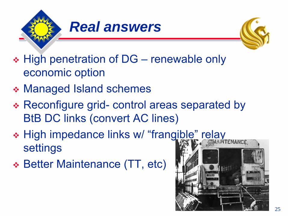
Real answers
High penetration of DG – renewable only economic optionManaged Island schemesReconfigure grid- control areas separated by BtB DC links (convert AC lines)High impedance links w/ “frangible” relay settingsBetter Maintenance (TT, etc)

26
3 Phase Power
Actually, a “Blinding Flash of The Obvious”…
27
Idea: DC at “The Links”
Generation at BtB Links:Natural DC Sources“Un-Natural” DC Sources
Storage Injection at BtB LinksControl Areas Finally take Control:
Reactive Power Control (VAR)Real Power ControlPhase Balance (reduce Negative Sequence)

28
Another Idea:
Control Areas Use Permissive PLCC to Maintain Generation During Disturbances
No Freq Push issues with high penetrationCertainty with down linesProvides CA Shutdown Capability during Over Gen

29
Natural HMW DC Sources – PV Arrays

30
Natural HMW DC Sources – Wind & Ocean

31
Un-natural MW DC sources: GTs
DC output relieves many constraints, with high RPM, smaller mass
32
Utility Needs: HMW Converters
Stay online until at least 58 Hz PLCC Permissive for DG
Ability to call for VAR support (w/compensation)Ability to call forth storage (w/ comp)Ability to shutdown DG by areaNeed transient power boost (equiv H)- spinning ResvNeed 10 min reserve (mimic quick start peakers) from storageNeed long term reserve from storage

33
Old View – Island BAD

34
New View – Island GOOD

35
System Evolution
20s 60s Now Future

36
Florida Solar Energy CenterCreating Energy Independence Since 1975
A Research Institute of the University of Central Florida