UST System Design
54
Transcript of UST System Design


• UST system designs must meet current UST
performance standards (15A NCAC 2N)
• UST system designs must be certified by a North
Carolina professional engineer
UST System Design

UST System Design
• 15A NCAC 2N “Criteria and Standards
Applicable to Underground Storage Tanks” – Section .0900 “Performance Standards for UST Systems
and UST System Component Installation or Replacement
Completed on or After November 1, 2007”
• Other Non-UST Section Standards (e.g., Fire
Codes, NCDENR Air Quality Standards,
Building Codes)

UST System Design
15A NCAC 2N .0900 affect:
• Installations completed on or after
November 1st, 2007
• Replacements on existing UST systems on or
after November 1st, 2007
• Notification requirements

UST System Design
15A NCAC 2N .0900 applies to:
Tanks
Piping
Associated components (e.g., dispensers,
submersible turbine pumps)
Containment sumps

UST System Design
15A NCAC 2N .0900 applies to:
Spill buckets
Siting for new and replacement systems
Operation and maintenance
Emergency generator tanks

UST System Design
15A NCAC 2N .0900 does not apply to:
Vent lines
Vapor recovery systems
Gravity-fed vertical fill ports

UST System Design
Fiberglass Reinforced Plastic (FRP)
Tanks
Double-Walled

UST System Design
Fiberglass Reinforced Plastic (FRP)
Steel Clad with FRP or
Polyurethane
Tanks
Double-Walled

UST System Design
Fiberglass Reinforced Plastic (FRP)
Steel Clad with FRP or
Polyurethane
Steel Jacketed with FRP
Tanks
Double-Walled

UST System Design
Fiberglass Reinforced Plastic (FRP)
Steel Clad with FRP or
Polyurethane
Steel Jacketed with FRP
Steel with Cathodic Protection
Tanks
Double-Walled

UST System Design
Tanks
Double-Walled with Continuous Monitoring
Vacuum
Pressure
Hydrostatic (Brine)

UST System Design
Tanks
Double-Walled with Continuous Monitoring
Vacuum
Pressure
Hydrostatic (Brine)
In NC, dual-float hydrostatic
sensors are required

UST System Design
Vacuum
Pressure
Hydrostatic (Brine)
Liquid Detecting Sensor w/
Periodic Interstitial Tightness Tests
Tanks
Double-Walled with Continuous Monitoring

UST System Design

UST System Design
Sensor must be at lowest point within interstice
•Location must be verifiable (e.g., position-
sensitive sensor)

UST System Design
Periodic Interstitial Tightness Tests (0.1 gph)
•Conducted at startup
•Within 6-12 months of startup
•Every 3 years thereafter

UST System Design
Interstitial tightness tests are NOT the
same as tank tightness tests.
Only specific tank make and models
have 3rd-party certified tests available

UST System Design

UST System Design
Retrofits: Make sure position-
sensitive sensor will fit
Retrofits: Make sure tank has an
interstitial tightness test available

UST System Design
Double-walled
Non-corrodible
UL 971 “Nonmetallic Underground
Piping For Flammable Liquids”
Piping

UST System Design
Vacuum
Pressure
Hydrostatic
Electronic liquid-detecting sensor in
sump that piping interstice drains
to with primary and secondary wall
integrity test every three years
Piping
Double-Walled with Continuous Monitoring

Double-walled piping monitored with
sump sensors must have interstice
open to containment sumps


UST System Design
Piping must be installed with
a means to locate it
(e.g., detectable tape
commonly used by
utilities)
Detectable Tape

UST System Design
Provides:
Remote detection
Provides early warning
during excavation / drilling
Detectable Tape

UST System Design
Consider:
Maximum detectable depth
Active vs. passive detection
Detectable Tape
Consider using one strip of
detectable tape per line

UST System Design
Pressurized piping must still
have Automatic Line Leak
Detectors (ALLDs)
Suction piping, including
European, and siphon bars
must meet new standards
Metal fittings, flex connectors
and single-walled components
must be in monitored
containment sumps
Piping

UST System Design
Underground ancillary
equipment
Dispensers
Line leak detectors
Submersible pumps
Remote fill pipes, etc.
Associated Components
Secondary containment with interstitial monitoring required: (Must maintain 12 months of monthly printed records of release detection results
and alarm history)

UST System Design
Designed, constructed,
installed, and maintained to
prevent water infiltration
Visually inspected annually
Non-corrodible
Containment Sumps

UST System Design
• Vacuum
• Pressure
• Hydrostatic
• Electronic liquid-detecting
sensor no more than two
inches from sump bottom
with integrity test every
three years
Containment Sumps
Continuous interstitial monitoring required: (Must maintain 12 months of monthly printed records of release detection results
and alarm history)

• Containment Sump
• Sump Sensor
• Submersible Turbine Pump
• ALLD

Reminder: All metal or single-walled
components must be installed within
monitored containment sumps

Spill Buckets
• Double-walled
• Non-corrodible OR isolated
from backfill
• Prefabricated
• Designed, constructed,
installed and maintained to
prevent water infiltration

• Vacuum
• Pressure
• Hydrostatic
• Electronic liquid-detecting
sensor with integrity test
every three years
Spill Buckets
Continuous interstitial monitoring required: (Must maintain 12 months of monthly printed records
of release detection results and alarm history)

• Automatic Shutoff (e.g., Flapper Valve)
• Vent Restriction Device (e.g., Ball Float)
• Overfill Alarm
Overfill Prevention
Overfill prevention equipment must be
tested annually for functionality

Ball floats cannot be used with
pressurized deliveries
Ball floats cannot be used with
suction pumps with air eliminators
Ball floats cannot be used with
coaxial Stage I vapor recovery
Ball floats cannot be used with gauge
opening-style fills

When installing both a flapper valve and
ball float, the flapper valve must be installed
below the level of the ball float

Overfill alarms must be located within
visual/audible distance to fill port

UST System Design
• Must be certified by a third-party in accordance with
federal UST requirements
• Must be compatible with product that they may come
in contact with
• Electronic liquid-detecting sensors must detect any
liquid and activate an alarm
Electronic Sensors (Interstitial / Sump Sensors)
Discriminating sensors must alarm in
both water and product
Any liquid detected must be removed
within 48 hours

UST System Design
• Must be compatible with the
electronic sensors being used
• Provide a printed record of release
detection results
• Provide a printed record of alarm
history
Monitoring Console

UST System Design
• In contact with contaminated soil or free product
Siting UST Systems
UST systems and UST system components prohibited
from being installed:
If contamination is discovered during excavation,
you must contact the UST Section - Corrective
Action Branch at the appropriate NCDENR
Regional Office before continuing.

UST System Design
Siting UST Systems
• Minimum of 2 feet of clean
backfill between tank and
sidewalls of excavation
• Minimum of 1 foot of clean
backfill underneath tank
After contaminated soils are
removed under the direction
of the UST Section –
Corrective Action Branch:

UST System Design
Siting UST Systems
• Minimum of 6 inches of clean
backfill on sides and beneath
piping
After contaminated soils are
removed under the direction
of the UST Section –
Corrective Action Branch:

UST System Design
• Within 100 feet of well serving public water system
• Within 50 feet of any other well (human consumption)
Siting UST Systems
UST systems and UST system components prohibited
from being installed:
During the UST system design phase, the presence of
any wells on and off the property should be investigated

UST System Design
• Must comply with the
new performance
standards including
secondary containment
and interstitial
monitoring
Emergency Generator UST Systems

Periodic Testing Requirements
Tanks (interstice monitored with liquid-
detecting sensor)
• Periodic Interstitial Tightness Test
– Must be capable of detecting 0.1 gph
leak
– Must be third-party certified
– Must be conducted at startup, within
6 and 12 months of startup and
every 3 years thereafter

Periodic Testing Requirements
Piping (interstice monitored
with liquid-detecting
sensor)
• Integrity test of primary
piping (i.e., line leak test)
• Integrity test on
secondary piping (i.e., air
test on interstice)
• Maintain results of most
recent tests
Periodic Testing Requirements
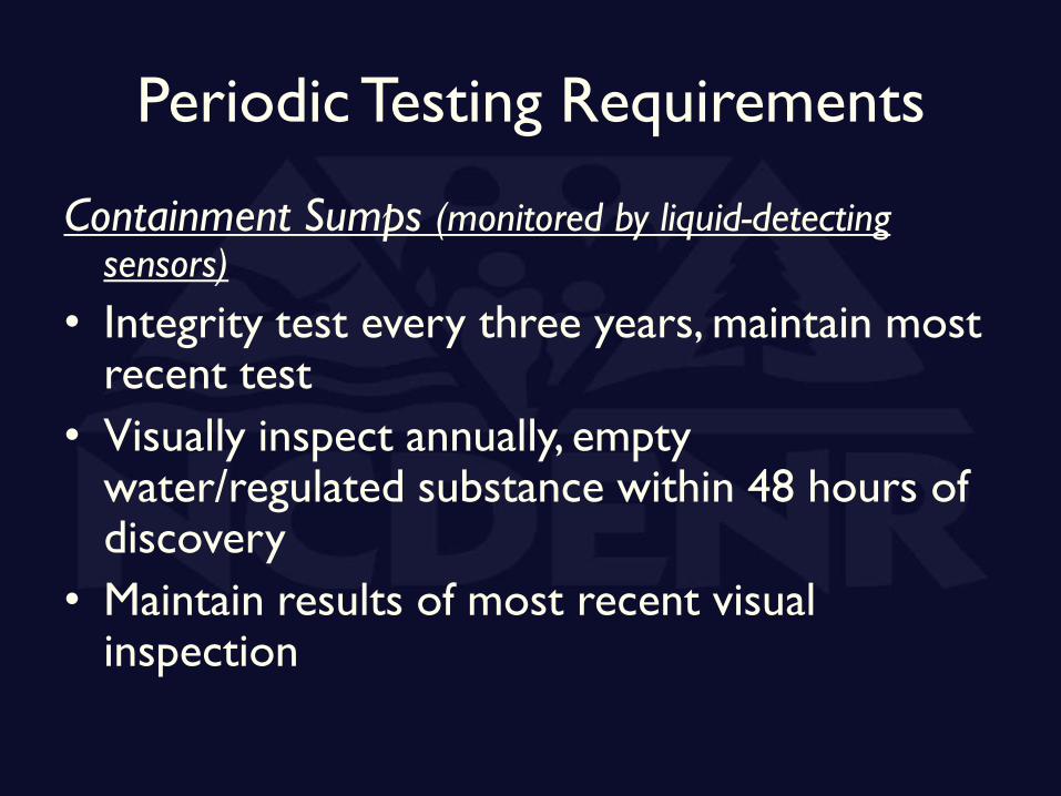
Containment Sumps (monitored by liquid-detecting sensors)
• Integrity test every three years, maintain most recent test
• Visually inspect annually, empty water/regulated substance within 48 hours of discovery
• Maintain results of most recent visual inspection

Periodic Testing Requirements
Spill Buckets (monitored by
liquid-detecting sensors)
• Integrity test of primary
and secondary walls
every three years
• Maintain results of most
recent test

Periodic Testing Requirements
Overfill Prevention Equipment
• Checked annually for
operability and proper
operating condition
• Maintain results of most
recent check

Periodic Testing Requirements
Automatic Line Leak
Detectors (ALLD)
• Annual functionality test
• Maintain results of most
recent test

Periodic Testing Requirements
Electronic monitoring sensors
• Checked annually for operability, proper
operating condition and proper calibration
• Maintain results of most recent check