Using the Serial FlashLoader With the Quartus II Software · Using the Serial FlashLoader With the...
22
Altera Corporation 1 AN-370-3.0 Preliminary Application Note 370 Using the Serial FlashLoader With the Quartus II Software Introduction Using the Joint Test Action Group (JTAG) interface, the Altera ® Serial FlashLoader (SFL) is the first in-system programming solution for Altera serial configuration devices. The SFL is available with the Quartus ® II software, version 4.1 SP1 and higher. SFL Megafunction is available with Quartus II version 6.0 and higher. Because serial configuration devices do not support the JTAG interface, the conventional method to program them is via the active serial (AS) programming interface. With the AS programming interface, the configuration data used to program serial configuration devices is downloaded via programming hardware. However, with the SFL you can program serial configuration devices in-system via the JTAG interface. To do so, use an FPGA as a bridge between the JTAG interface and the serial configuration device. Figure 1 shows both the conventional method of programming serial configuration devices as well as the in-system programming method using the SFL solution. Table 1 lists the advantages and disadvantages of both methods. SFL supports FPGA families that configure using active serial configuration scheme. With SFL Megafunction, you can instantiate SFL image into user design. This feature allows you to do SFL programming without resetting the user design in the FPGA. The SFL solution provides more hardware programming options. For example, you can use the ByteBlaster ™ II or USB-Blaster ™ download cable, production tester, and other tools that have a JTAG interface. Table 1. Advantages & Disadvantages Method Advantage Disadvantage Conventional: (Active Serial Programming) Simple and fast Requires separate programming interface to configure FPGAs and program serial configuration devices. SFL solution: (JTAG Programming) Able to configure the FPGA and program serial configuration devices using the same JTAG interface Slow because the SFL solution needs to configure the FPGA before programming serial configuration devices. July 2006, ver. 3.0
-
Upload
duongquynh -
Category
Documents
-
view
237 -
download
2
Transcript of Using the Serial FlashLoader With the Quartus II Software · Using the Serial FlashLoader With the...

AN-370-3.0
July 2006, ver. 3.0
Using the Serial FlashLoaderWith the Quartus II Software
Application Note 370
Altera Corporation 1
Introduction Using the Joint Test Action Group (JTAG) interface, the Altera® Serial FlashLoader (SFL) is the first in-system programming solution for Altera serial configuration devices. The SFL is available with the Quartus® II software, version 4.1 SP1 and higher. SFL Megafunction is available with Quartus II version 6.0 and higher.
Because serial configuration devices do not support the JTAG interface, the conventional method to program them is via the active serial (AS) programming interface. With the AS programming interface, the configuration data used to program serial configuration devices is downloaded via programming hardware.
However, with the SFL you can program serial configuration devices in-system via the JTAG interface. To do so, use an FPGA as a bridge between the JTAG interface and the serial configuration device. Figure 1 shows both the conventional method of programming serial configuration devices as well as the in-system programming method using the SFL solution. Table 1 lists the advantages and disadvantages of both methods.
SFL supports FPGA families that configure using active serial configuration scheme. With SFL Megafunction, you can instantiate SFL image into user design. This feature allows you to do SFL programming without resetting the user design in the FPGA. The SFL solution provides more hardware programming options. For example, you can use the ByteBlaster™ II or USB-Blaster™ download cable, production tester, and other tools that have a JTAG interface.
Table 1. Advantages & Disadvantages
Method Advantage Disadvantage
Conventional: (Active Serial Programming)
Simple and fast Requires separate programming interface to configure FPGAs and program serial configuration devices.
SFL solution: (JTAG Programming)
Able to configure the FPGA and program serial configuration devices using the same JTAG interface
Slow because the SFL solution needs to configure the FPGA before programming serial configuration devices.
Preliminary

Using the Serial FlashLoader With the Quartus II Software
1 Whenever the term “serial configuration device(s)” is used in this document, it refers to Altera EPCS1, EPCS4, EPCS16, and EPCS64 devices.
This application note describes the following:
■ Programming single and multiple serial configuration devices with the SFL solution
■ Generating programming files in Quartus II software■ Using SFL Megafunction in Quartus II software■ Programming serial configuration devices with JIC or Jam™ files
Figure 1. Conventional Versus the In-System Programming Method
ByteBlaster II Download Cable, Microprocessor, etc.
Conventional Method of Programming Serial Configuration Devices Via the AS Interface
FPGA
Serial Configuration Device
AS Interface
SFL Image to bridge theJTAG interface and ASMI
FPGA
JTAG ASMISerial Configuration DeviceAS InterfaceJTAG Interface
JTAG Chain
In-System Method of Programming Serial Configuration Devices Via the JTAG Interface
2 Altera CorporationPreliminary

Steps for Programming Single & Multiple Serial Configuration Devices With the SFL Solution
Steps for Programming Single & Multiple Serial Configuration Devices With the SFL Solution
This section describes the three steps to program both single and multiple serial configuration devices with the SFL solution.
To program serial configuration devices using the SFL solution, follow these steps (see Figures 2, 3, and 4):
1. To bridge the JTAG interface with the active serial memory interface (ASMI) block in the FPGA device, configure the SFL image into the FPGA. The previous design will be replaced with the SFL image.
2. Program the serial configuration device(s) via the SFL image’s JTAG-ASMI bridge.
1 You can bypass this step if the SFL image existed in the FPGA.
3. Reconfigure the FPGA with the new configuration data. The SFL image will be replaced with the new design. To reconfigure the FPGA with the new configuration data, pull the nConfig pin low and release it to start configuration.
Altera Corporation 3Preliminary

Using the Serial FlashLoader With the Quartus II Software
Figure 2. Serial Flash Loader Programming Flow
Step 1:
Configure SFL image
into FPGA
Start
Step 2:
Program EPCS through
SFL
Step 3:
Reconfigure FPGA with
new EPCS image
SFL image exist in
the FPGA?
No
Yes
4 Altera CorporationPreliminary

Steps for Programming Single & Multiple Serial Configuration Devices With the SFL Solution
Altera Corporation 5
Figure 3. Programming a Single Serial Configuration Device With the SFL Solution
Note to Figure 3: (1) You can bypass this step if the SFL image existed in the FPGA.
JTAG ASMI
FPGA
FPGA ConfigurationImage
JTAG ASMI
FPGA
SFL ImageBridge
JTAG ASMI
FPGA
SFL ImageBridge
FPGA with User Configuration
Step 1: Configure (1)
Step 2: Program
SerialConfigurationDevice
SerialConfigurationDevice
SerialConfigurationDevice
JTAG Chain
JTAG Chain
SFL Image BridgeJTAG ASSerial ConfigurationDevice
JTAG Chain
JTAG ASMI
FPGA
Step 3: Reconfigure SerialConfigurationDevice
JTAG Chain
New FPGA Configuration Image
Preliminary

Using the Serial FlashLoader With the Quartus II Software
Figure 4 shows the process for programming multiple serial configuration devices with the SFL solution.
Figure 4. Programming Multiple Serial Configuration Devices with the SFL Solution
Notes to Figure 4:(1) “1st device” and “2nd device” represent serial configuration devices.(2) You can bypass this step if the SFL image existed in the FPGA.
JTAG
ASMI
FPGA#1
FPGA Configuration Image
JTAG Chain
1st Device (1)
JTAGFPGA#2
FPGA Configuration Image
2nd Device (1)
ASMI
JTAG
ASMI
FPGA#1
JTAG Chain
1st Device (1)
FPGA#2
2nd Device (1)
FPGA with User Configuration
Step 1: Configure (2)SFL ImageBridge
SFL ImageBridge
JTAG
ASMI
JTAG
ASMI
FPGA#1
JTAG Chain
1st Device (1)
FPGA#2
2nd Device (1)
Step 2: ProgramSFL ImageBridge
SFL ImageBridge
JTAG
ASMI
JTAG
ASMI
FPGA#1
JTAG Chain
1st Device (1)
FPGA#2
2nd Device (1)
Step 3: Reconfigure
JTAG
ASMI
JTAG
FPGA Configuration Image
FPGA Configuration Image
6 Altera CorporationPreliminary

Using the Serial Flash Loader Megafunction in Quartus II Software
Altera Corporation 7
Using the Serial Flash Loader Megafunction in Quartus II Software
SFL Megafunction allows you to instantiate the SFL image into your design. This feature allows SFL programming without resetting your design in the FPGA with the SFL image.
Instantiating SFL Megafunction in the Quartus II Software
Perform the following steps to generate a SFL Megafunction instantiation. You should then instantiate the SFL Megafunction in your FPGA top-level design.
1. Choose MegaWizard Plug-In Manager (Tools menu).
2. Select Create a new custom megafunction variation and click Next.
3. Select the FPGA device family.
4. Select Serial Flash Loader from the Megafunction list.
5. Select the Hardware Description Language (HDL) output file type and name the file. Click Next (Verilog HDL was chosen for this example). After making these settings, the dialog box appears, as shown in Figure 5.
Preliminary

Using the Serial FlashLoader With the Quartus II Software
8 Altera Corporation
Figure 5. SFL Megafunction Settings
Preliminary

Using the Serial Flash Loader Megafunction in Quartus II Software
6. Specify the directory and output filename. Click Next, as shown in Figure 6.
Figure 6. SFL Megafunction Parameter Settings
Altera Corporation 9Preliminary

Using the Serial FlashLoader With the Quartus II Software
7. Check the Share ASMI interface with your design check box if you need to share the ASMI interface with your design. This option provides additional control pins for controlling the ASMI interface, as shown in Figure 7.
Figure 7. SFL Megafunction with "Share ASMI interface with your design" Option
8. Click Next until you reach the summary page.
9. Click Finish to generate the SFL Megafunction. Quartus II software generates the megafunction in the form of the HDL file you specified.
Table 2. Input and Output Signals for the SFL Megafunction (Part 1 of 2)
DCLK_IN (1) Input Clock signal from user design to DCLK.
nCSO_IN (1) Input Control signal from user design to nCSO pin. A low signal enables the EPCS.
ASDO_IN (1) Input Control signal from user design to ASDO pin for sending data into EPCS.
nOE_IN Input Control signal to enable the SFL Megafunction. A low signal enables the Megafunction. SFL tri-states ASMI interface when it is disabled.
10 Altera CorporationPreliminary

Generating Programming Files in the Quartus II Software
Generating Programming Files in the Quartus II Software
You can program serial configuration devices with either JTAG indirect configuration (.jic) or Jam (an ASCII text file in the STAPL format) programming files. To generate JIC or Jam programming files with the Quartus II software, you first need to generate a user-specified SRAM object file (.sof), which is the input file. Next, you need to convert the SOF to a JIC file. Alternatively, if you prefer to use Jam programming files, you will need to convert the JIC file to a Jam file. This section provides the instructions and describes:
■ Converting SOF to JIC files■ Converting JIC files to Jam files■ Reviewing JIC and Jam file contents
Converting SOF to JIC Files in Quartus II Software
To convert a SOF to a JIC file, follow these steps:
1. Choose Convert Programming Files (File menu).
2. In the Convert Programming Files dialog box, scroll to the JTAG Indirect Configuration File (.jic) from the Programming file type field.
3. In the Configuration device field, specify the targeted serial configuration device.
ASMI_ACCESS_GRANTED (1) Input Control signal to allow SFL to access the DCLK, nCSO, ADSO and DATA0 pins using the ASMI interface. A high signal allows SFL to access the ASMI interface. A low signal allows user design to access to ASMI interface.
DATA0_OUT (1) Output Signal from DATA0 pin to user design.
ASMI_ACCESS_REQUEST (1) Output A high signal indicates SFL is requesting ASMI interface access. SFL starts accessing ASMI interface when ASMI_ACCESS_GRANTED is high.
Note for Table 2:(1) These ports are available when “Share ASMI interface with your design” option is
selected in the megafunction.
Table 2. Input and Output Signals for the SFL Megafunction (Part 2 of 2)
Altera Corporation 11Preliminary

Using the Serial FlashLoader With the Quartus II Software
4. In the File name field, browse to the target directory and specify an output file name.
5. Highlight the SOF data in the Input files to convert section. See Figure 8.
Figure 8. Convert Programming Files Dialog Box
6. Click Add File.
7. Select the SOF that you want to convert to a JIC file.
8. Click OK.
12 Altera CorporationPreliminary

Generating Programming Files in the Quartus II Software
9. Highlight FlashLoader and click Add Device. See Figure 9.
Figure 9. Highlight FlashLoader
10. Click OK. The Select Devices page displays.
11. Select the targeted FPGA that you are using to program the serial configuration device. See Figure 10.
Altera Corporation 13Preliminary

Using the Serial FlashLoader With the Quartus II Software
Figure 10. Select Devices Page
12. Click OK. The Convert Programming Files page displays. See Figure 11.
Figure 11. Convert Programming Files Page
14 Altera CorporationPreliminary

Generating Programming Files in the Quartus II Software
13. Click OK.
1 To program the serial configuration device(s) with the JIC file that you just created, add the file to the Quartus II Programmer window and follow the steps in “Programming Serial Configuration Devices Using the Quartus II Programmer & JIC Files” on page 17.
Converting JIC Files to Jam Files in the Quartus II Software
To convert a JIC to a Jam file in the Quartus II software, follow these steps:
1. Choose Programmer (Tools menu).
2. Click Add File. The Select Programming File window displays.
3. Browse to the JIC file that was created in “Converting SOF to JIC Files in Quartus II Software” on page 11. Add more JIC files if you are programming multiple serial configuration devices.
4. Click Open.
5. Choose Create/Update and scroll to Create JAM, SVF, or ISC File (File menu). See Figure 12.
Figure 12. Create Jam, SVF, or ISC File
Altera Corporation 15Preliminary

Using the Serial FlashLoader With the Quartus II Software
6. The Create JAM, SVF, or ISC File window displays. See Figure 13.
Figure 13. Converting a JIC File to a Jam File in the Quartus II Software
7. Click OK.
1 To program the serial configuration device(s) with the Jam file that you just created, add the file to the Quartus II Programmer window and follow the steps in “Programming Serial Configuration Devices Using the Quartus II Programmer & Jam Files” on page 19.
JIC & Jam File Contents
The JIC and Jam files contain:
■ A configuration image of the SFL:● Created by Quartus II software when you select the targeted
FPGA during file conversion (that is, from SOF to JIC file).● Configured into the FPGA before the serial configuration device
is programmed.■ Programming data for serial configuration devices:
● Derived from the SOF.● Transferred into the serial configuration device during
programming.
16 Altera CorporationPreliminary

Programming Serial Configuration Devices With the Quartus II Programmer
Figure 14 illustrates the generation of the SFL programming file.
Figure 14. Generation of the SFL Programming File
Programming Serial Configuration Devices With the Quartus II Programmer
You can use the Quartus II Programmer to generate serial configuration device programming files. The Quartus II Programmer can generate both JIC and Jam files with the SFL.
This section discusses:
■ Programming serial configuration devices using the Quartus II Programmer and JIC files
■ Programming serial configuration devices using the Quartus II Programmer and Jam files
Programming Serial Configuration Devices Using the Quartus II Programmer & JIC Files
Use the following steps to program serial configuration devices with JIC files.
1. When the SOF-to-JIC file conversion is complete (refer to Figure 11 on page 14), add the JIC file to the Quartus II Programmer window:
a. Choose Programmer (Tools menu). The Chain1.cdf window displays.
b. Click Add File. From the Select Programming File page, browse to the JIC file.
c. Click Open.
SFLDesign
(Based onFPGA)
SFLProgramming
File
SFL Image
Serial Configuration
Device Programming
Data
SOF User
Design
Altera Corporation 17Preliminary

Using the Serial FlashLoader With the Quartus II Software
2. Configure the FPGA with the SFL image by checking the FPGA Program/Configure box (see Figure 15). This process corresponds to Step 1 of Figure 3 on page 5.
3. Program the serial configuration device by checking the corresponding Program/Configure box (see Figure 15). This process corresponds to Step 2 of Figure 3 on page 5.
4. Click Start.
Figure 15 shows the Quartus II Programmer window with one JIC file.
Figure 15. Quartus II Programmer Window With One JIC File
1 If the Program/Configure check boxes are not specified, the Quartus II Programmer bypasses the request. Also, if the FPGA does not have the SFL image when the serial configuration device data is programmed via the JTAG interface, the programming process fails.
You can program multiple serial configuration devices by including more than one JIC file in the Quartus II programmer.
1 FPGA has to be in active serial configuration mode to enable SFL to program.
FPGA check box
Step 1: Check this box to configure the SFL image intothe FPGA.
Serial configurationdevice check box.
Step 2: Check this box to program the serialconfiguration device.
Step 3: Click Start.
18 Altera CorporationPreliminary

Programming Serial Configuration Devices With the Quartus II Programmer
Figure 16 shows the Quartus II Programmer window with multiple JIC files.
Figure 16. Quartus II Programmer Window With Multiple JIC Files
Programming Serial Configuration Devices Using the Quartus II Programmer & Jam Files
When programming with Jam files, the Quartus II Programmer requires that you configure the FPGA and program the serial configuration device in one step, which is why Figure 17 shows just one Program/Configure check box.
Use the following steps to program serial configuration devices with Jam files.
1. When the JIC-to-Jam file conversion is complete (refer to Figure 13 on page 16), add the Jam file to the Quartus II Programmer window:
a. Choose Programmer (Tools menu). The Chain1.cdf window displays.
b. Click Add File. From the Select Programming File page, browse to the Jam file.
c. Click Open.
Altera Corporation 19Preliminary

Using the Serial FlashLoader With the Quartus II Software
2. Configure the FPGA with the SFL image, and program the serial configuration device by checking the FPGA Program/Configure box (see Figure 17). This process corresponds to Step 1 and Step 2 of Figure 3 on page 5.
3. Click Start.
1 The Jam file is generated from the JIC file via the chain description file (.cdf). Refer to Quartus II Help for more information.
Figure 17 shows the Quartus II Programmer window with one Jam file.
Figure 17. Quartus II Programmer Window With One Jam File
20 Altera CorporationPreliminary
Conclusion
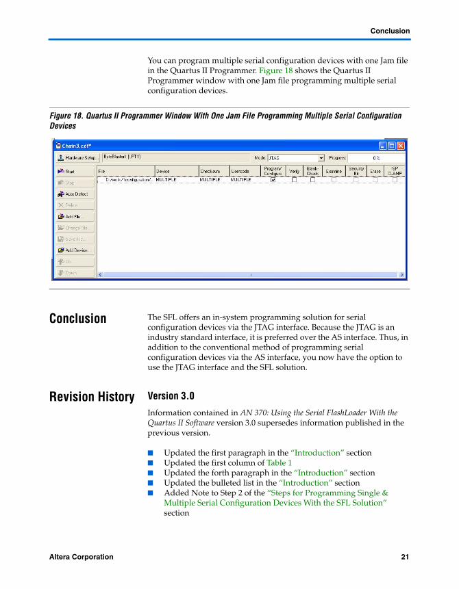
You can program multiple serial configuration devices with one Jam file in the Quartus II Programmer. Figure 18 shows the Quartus II Programmer window with one Jam file programming multiple serial configuration devices.
Figure 18. Quartus II Programmer Window With One Jam File Programming Multiple Serial Configuration Devices
Conclusion The SFL offers an in-system programming solution for serial configuration devices via the JTAG interface. Because the JTAG is an industry standard interface, it is preferred over the AS interface. Thus, in addition to the conventional method of programming serial configuration devices via the AS interface, you now have the option to use the JTAG interface and the SFL solution.
Revision History Version 3.0
Information contained in AN 370: Using the Serial FlashLoader With the Quartus II Software version 3.0 supersedes information published in the previous version.
■ Updated the first paragraph in the “Introduction” section■ Updated the first column of Table 1■ Updated the forth paragraph in the “Introduction” section■ Updated the bulleted list in the “Introduction” section■ Added Note to Step 2 of the “Steps for Programming Single &
Multiple Serial Configuration Devices With the SFL Solution” section
Altera Corporation 21Preliminary

Using the Serial FlashLoader With the Quartus II Software
■ Added Figure 2 to the “Steps for Programming Single & Multiple Serial Configuration Devices With the SFL Solution” section
■ Added notes to Figures 3 and 4■ Added the “Using the Serial Flash Loader Megafunction in Quartus
II Software” section■ Added a note to Figure 11 and after Figure 11
Version 2.0
Information contained in AN 370: Using the Serial FlashLoader With the Quartus II Software version 2.0 supersedes information published in the previous version.
■ Updated the first and forth paragraph and the bulleted list in the “Introduction” section
■ Updated column one of Table 1■ Updated steps 2 and 3 in the “Steps for Programming Single &
Multiple Serial Configuration Devices With the SFL Solution” section
22 Altera CorporationPreliminary
101 Innovation DriveSan Jose, CA 95134(408) 544-7000www.altera.comApplications Hotline:(800) 800-EPLDLiterature Services:[email protected]
Copyright © 2006 Altera Corporation. All rights reserved. Altera, The Programmable Solutions Company,the stylized Altera logo, specific device designations, and all other words and logos that are identified astrademarks and/or service marks are, unless noted otherwise, the trademarks and service marks of AlteraCorporation in the U.S. and other countries. All other product or service names are the property of their re-spective holders. Altera products are protected under numerous U.S. and foreign patents and pendingapplications, maskwork rights, and copyrights. Altera warrants performance of its semiconductor productsto current specifications in accordance with Altera's standard warranty, but reserves the right to make chang-es to any products and services at any time without notice. Altera assumes noresponsibility or liability arising out of the application or use of any information, product,or service described herein except as expressly agreed to in writing by Altera Corpora-tion. Altera customers are advised to obtain the latest version of device specificationsbefore relying on any published information and before placing orders for products orservices.