Using the RTDS Simulator for the Analysis of Automatic ...ucaiug.org/Meetings/CIGRE_2014/USB Promo...
24
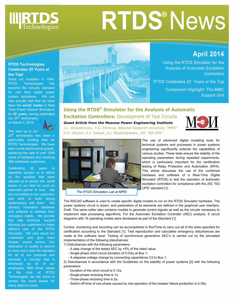
RTDS Technologies Celebrates 20 Years at the Top! Since our inception in 1994, RTDS Technologies has become the industry standard for real time digital power system simulators. We can now proudly add that we have been the world leader in Real Time Power System Simulators for 20 years, having celebrated our 20 th anniversary on March 4, 2014. The lead up to our 20 th anniversary has been a particularly exciting time for RTDS Technologies. We have seen some phenomenal growth, achieving the sale of over 1000 racks of hardware and reaching 300 worldwide customers. Celebrating 20 years in operation causes us to reflect on the qualities that have allowed us to remain the world leader in our field for such an extended period of time. We are committed to our customers and work to build strong relationships with them. We develop innovative hardware and software to address their simulation needs. We provide first rate technical support allowing our customers to make efficient use of the RTDS Simulator. We care about our customers and give them honest, sound advice. Our dedication to quality is second to none and it sets the standard for all of our products and services; a concept that is embraced by all of our employees. With these values at the core of RTDS Technologies, we will strive to remain the world leader for many years to come. Using the RTDS ® Simulator for the Analysis of Automatic Excitation Controllers: Development of Test Circuits The use of advanced digital modeling tools for technical systems and processes in power systems engineering significantly extends the capabilities of various studies. These tests ensure the stability of the operating parameters during repeated experiments, which is particularly important for the certification testing of Relay Protection and Automation (RPA). This article discusses the use of the combined hardware and software of a Real-Time Digital Simulator (RTDS) to test the operation of automatic excitation controllers for compliance with the JSC "SO UPS" standard [1]. The RSCAD software is used to create specific digital models to run on the RTDS Simulator hardware. The power systems circuit is drawn, and parameters of its elements are defined in the graphical user interface, Draft. The same editor also contains models to generate control signals as well as the circuits necessary to implement data processing algorithms. For the Automatic Excitation Controller (AEC) analysis, 6 circuit diagrams with 16 operating modes were developed as part of the Standard [1]. Control, monitoring and recording can be accomplished in RunTime to carry out all of the tests specified for certification according to the Standard [1]. Test reproduction and calculated emergency disturbances are made at the software level. Testing of synchronous generators AEC’s is carried out by the simulated implementation of the following disturbances: 1) Disturbances with the following parameters: - A step change of the tested AEC by +5% of the rated value; - Single-phase short circuit (duration of 0.03s) at Bus 1; - A stepwise voltage change by connecting capacitance C3 to Bus 1; 2) Disturbances in accordance with the Guidelines on the stability of power systems [2] with the following parameters: - Duration of the short circuit is 0.12s; - Single-phase reclosing time is 1s; - Three-phase reclosing time is 2s; - Switch-off time of one phase caused by mis-operation of the breaker failure protection is 0.35s; April 2014 Using the RTDS Simulator for the Analysis of Automatic Excitation Controllers RTDS Celebrates 20 Years at the Top Component Highlight: The MMC Support Unit RTDS News ® Guest Article from the Moscow Power Engineering Institute J.L. Artsyshevsky, T.G. Klimova, National Research University "MPEI" A.V. Zhukov, E.I. Satsuk, A.I. Rasscheplyaev, JSC "SO UPS" The RTDS Simulation Lab at MPEI
Transcript of Using the RTDS Simulator for the Analysis of Automatic ...ucaiug.org/Meetings/CIGRE_2014/USB Promo...
RTDS Technologies Celebrates 20 Years at the Top! Since our inception in 1994, RTDS Technologies has become the industry standard for real time digital power system simulators. We can now proudly add that we have been the world leader in Real Time Power System Simulators for 20 years, having celebrated our 20th anniversary on March 4, 2014. The lead up to our 20th anniversary has been a particularly exciting time for RTDS Technologies. We have seen some phenomenal growth, achieving the sale of over 1000 racks of hardware and reaching 300 worldwide customers.
Celebrating 20 years in operation causes us to reflect on the qualities that have allowed us to remain the world leader in our field for such an extended period of time. We are committed to our customers and work to build strong relationships with them. We develop innovative hardware and software to address their simulation needs. We provide first rate technical support allowing our customers to make efficient use of the RTDS Simulator. We care about our customers and give them honest, sound advice. Our dedication to quality is second to none and it sets the standard for all of our products and services; a concept that is embraced by all of our employees. With these values at the core of RTDS Technologies, we will strive to remain the world leader for many years to come.
Using the RTDS® Simulator for the Analysis of Automatic Excitation Controllers: Development of Test Circuits
The use of advanced digital modeling tools for technical systems and processes in power systems engineering significantly extends the capabilities of various studies. These tests ensure the stability of the operating parameters during repeated experiments, which is particularly important for the certification testing of Relay Protection and Automation (RPA). This article discusses the use of the combined hardware and software of a Real-Time Digital Simulator (RTDS) to test the operation of automatic excitation controllers for compliance with the JSC "SO UPS" standard [1].
The RSCAD software is used to create specific digital models to run on the RTDS Simulator hardware. The power systems circuit is drawn, and parameters of its elements are defined in the graphical user interface, Draft. The same editor also contains models to generate control signals as well as the circuits necessary to implement data processing algorithms. For the Automatic Excitation Controller (AEC) analysis, 6 circuit diagrams with 16 operating modes were developed as part of the Standard [1]. Control, monitoring and recording can be accomplished in RunTime to carry out all of the tests specified for certification according to the Standard [1]. Test reproduction and calculated emergency disturbances are made at the software level. Testing of synchronous generators AEC’s is carried out by the simulated implementation of the following disturbances: 1) Disturbances with the following parameters: - A step change of the tested AEC by +5% of the rated value; - Single-phase short circuit (duration of 0.03s) at Bus 1; - A stepwise voltage change by connecting capacitance C3 to Bus 1; 2) Disturbances in accordance with the Guidelines on the stability of power systems [2] with the following parameters: - Duration of the short circuit is 0.12s; - Single-phase reclosing time is 1s; - Three-phase reclosing time is 2s; - Switch-off time of one phase caused by mis-operation of the breaker failure protection is 0.35s;
April 2014 Using the RTDS Simulator for the
Analysis of Automatic Excitation Controllers
RTDS Celebrates 20 Years at the Top
Component Highlight: The MMC Support Unit
RTDS News®
Guest Article from the Moscow Power Engineering Institute J.L. Artsyshevsky, T.G. Klimova, National Research University "MPEI" A.V. Zhukov, E.I. Satsuk, A.I. Rasscheplyaev, JSC "SO UPS"
The RTDS Simulation Lab at MPEI
RTDS Training Courses We are currently accepting registrations for the following course:
INTRODUCTORY RTDS SIMULATOR TRAINING
May 26—30 in Winnipeg, CANADA
Email [email protected] for more details.
**If you have suggestions for future training course topics, please don’t hesitate to get in touch.**
Upcoming Events
IEEE PES T&D
Chicago, USA
April 14-17, 2014
Booth 4621
PACWorld
Zagreb, CROATIA
June 23-26, 2014
RTDS India Users Group Meeting Kanpur, INDIA July 11-13. 2014
RTDS European Users Group Meeting Lyngby, DENMARK October 8-9, 2014
RTDS Technologies Inc., 100‐150 Innovation Drive, Winnipeg, MB R3T 2E1 CANADA
Phone: +1 204 989 9700 Fax: +1 204 452 4303 Email: [email protected] Website: www.rtds.com
Component Highlight: The MMC Support Unit RTDS Technologies’ FPGA-based MMC Support Unit is now being used by 17 clients in 8 different countries worldwide. With over 130 units currently in operation, manufacturers have once again put their trust in RTDS Technologies to provide solutions for the most complex power systems applications.
Detailed testing of physical MMC converter control equipment has been successfully completed by numerous manufacturers including ABB, ALSTOM, HICO, LSIS, NR, RXPE, SIEMENS, and XJ. In addition to testing the performance of the physical controllers of a particular converter, a number of simulation studies have been performed to evaluate overall network response and control interaction with other LCC and/or MMC based systems electrically near the scheme in question. This is an important and challenging aspect to consider when adding new HVDC converters to existing networks that are in close proximity to other HVDC links.
The MMC Support Unit uses a well-proven representation of the converter valve which has been available in RSCAD for several years. The processor version of the MMC valve model has been used by a large number of RTDS clients since its introduction in 2009. The more recently released FPGA version was introduced to overcome the difficulties of interconnecting the physical firing pulse controls as the number of MMC sub-modules in the converter increases. With the FPGA version, the user is able to accommodate interconnection of controllers for converters with more than 500 sub-modules (levels) per converter arm or over 3000 sub-modules per HVDC terminal.
The successful application of the RTDS Simulator for modern MMC-based systems serves to reinforce that, as the undeniable world leader in real time digital simulation, RTDS Technologies is also leading the way in real time modelling of MMC-based technology.
You can find us on:
In order to connect the tested AEC to the RTDS Simulator, an interface controller was designed. This controller contains a model of thyristor converter, controlled by a standard 6 pulse output from the AEC. It also includes a circuit which converts the signal from the output of the thyristor converter into a digital signal to be connected to the RTDS Simulator. All of the tests required by the JSC "SO UPS" Standard [1] were performed successfully using the RTDS Simulator. Being able to record and display all of the necessary parameters allows effective presentation of the results. In addition, it is possible to obtain the necessary numerical characteristics of the transient (transient time, damping constant, overshoot) by processing the results. The RTDS Simulator provides the opportunity to model operating conditions of the generating equipment in power systems of varying complexity in order to verify the operation of the AEC. It also allows existing algorithm or programming faults in the AEC to be rectified. Using real time digital simulation, the AEC can be adjusted for a particular power generating facility. BIBLIOGRAPHY 1. Standard of JSC "SO UPS" СТО 59012820.29.160.20.001-2012, approval date 03.04.2012. "Requirements to excitation systems and AUTOMATIC PD REGULATORS OF SYNCHRONOUS GENERATORS" 2. “Guidelines on the stability of power systems" (approved by the order of the Ministry of Energy of Russia 30.06.2003 № 277).
RTDS Technologies Inc. @RTDS_Simulator
To read the full article, please visit our website at www.rtds.com
Did you know?
RTDS Technologies recently welcome three new representatives to their team. With new representation in Chile, France and Germany, RTDS Technologies now has 24 worldwide representatives. Welcome to the team!
Please visit the Worldwide Representatives portion of the RTDS Technologies website for more details.
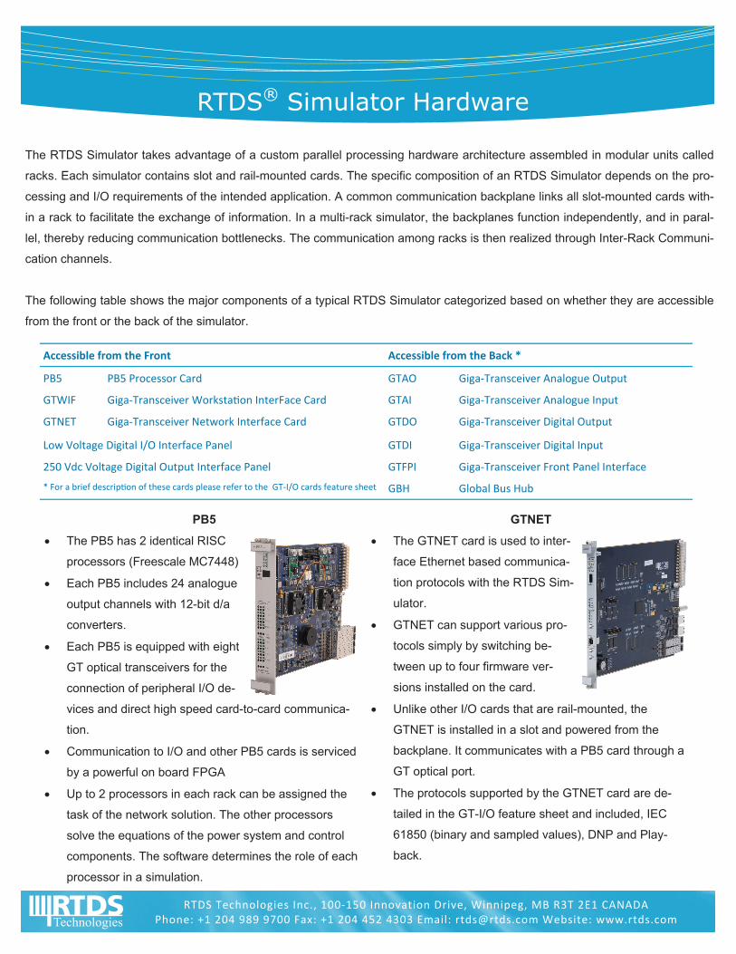
RTDS® Simulator Hardware
The RTDS Simulator takes advantage of a custom parallel processing hardware architecture assembled in modular units called
racks. Each simulator contains slot and rail-mounted cards. The specific composition of an RTDS Simulator depends on the pro-
cessing and I/O requirements of the intended application. A common communication backplane links all slot-mounted cards with-
in a rack to facilitate the exchange of information. In a multi-rack simulator, the backplanes function independently, and in paral-
lel, thereby reducing communication bottlenecks. The communication among racks is then realized through Inter-Rack Communi-
cation channels.
The following table shows the major components of a typical RTDS Simulator categorized based on whether they are accessible
from the front or the back of the simulator.
PB5
The PB5 has 2 identical RISC
processors (Freescale MC7448)
Each PB5 includes 24 analogue
output channels with 12-bit d/a
converters.
Each PB5 is equipped with eight
GT optical transceivers for the
connection of peripheral I/O de-
vices and direct high speed card-to-card communica-
tion.
Communication to I/O and other PB5 cards is serviced
by a powerful on board FPGA
Up to 2 processors in each rack can be assigned the
task of the network solution. The other processors
solve the equations of the power system and control
components. The software determines the role of each
processor in a simulation.
GTNET
The GTNET card is used to inter-
face Ethernet based communica-
tion protocols with the RTDS Sim-
ulator.
GTNET can support various pro-
tocols simply by switching be-
tween up to four firmware ver-
sions installed on the card.
Unlike other I/O cards that are rail-mounted, the
GTNET is installed in a slot and powered from the
backplane. It communicates with a PB5 card through a
GT optical port.
The protocols supported by the GTNET card are de-
tailed in the GT-I/O feature sheet and included, IEC
61850 (binary and sampled values), DNP and Play-
back.
Accessible from the Front Accessible from the Back *
PB5 PB5 Processor Card GTAO Giga‐Transceiver Analogue Output
GTWIF Giga‐Transceiver Worksta on InterFace Card GTAI Giga‐Transceiver Analogue Input
GTNET Giga‐Transceiver Network Interface Card GTDO Giga‐Transceiver Digital Output
Low Voltage Digital I/O Interface Panel GTDI Giga‐Transceiver Digital Input
250 Vdc Voltage Digital Output Interface Panel GTFPI Giga‐Transceiver Front Panel Interface
GBH Global Bus Hub * For a brief descrip on of these cards please refer to the GT‐I/O cards feature sheet
RTDS Technologies Inc., 100‐150 Innovation Drive, Winnipeg, MB R3T 2E1 CANADA Phone: +1 204 989 9700 Fax: +1 204 452 4303 Email: [email protected] Website: www.rtds.com
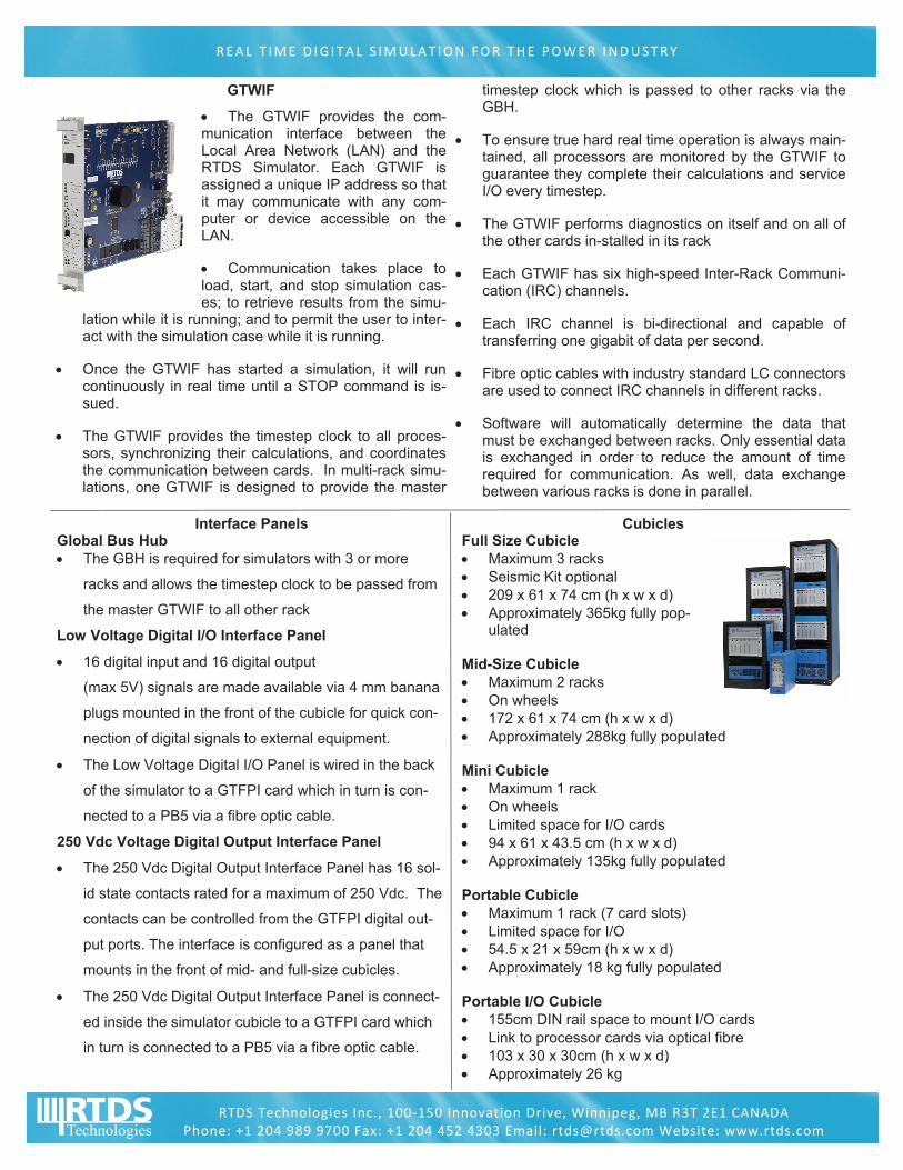
GTWIF
The GTWIF provides the com-munication interface between the Local Area Network (LAN) and the RTDS Simulator. Each GTWIF is assigned a unique IP address so that it may communicate with any com-puter or device accessible on the LAN.
Communication takes place to load, start, and stop simulation cas-es; to retrieve results from the simu-
lation while it is running; and to permit the user to inter-act with the simulation case while it is running.
Once the GTWIF has started a simulation, it will run continuously in real time until a STOP command is is-sued.
The GTWIF provides the timestep clock to all proces-sors, synchronizing their calculations, and coordinates the communication between cards. In multi-rack simu-lations, one GTWIF is designed to provide the master
timestep clock which is passed to other racks via the GBH.
To ensure true hard real time operation is always main-tained, all processors are monitored by the GTWIF to guarantee they complete their calculations and service I/O every timestep.
The GTWIF performs diagnostics on itself and on all of the other cards in-stalled in its rack
Each GTWIF has six high-speed Inter-Rack Communi-cation (IRC) channels.
Each IRC channel is bi-directional and capable of transferring one gigabit of data per second.
Fibre optic cables with industry standard LC connectors are used to connect IRC channels in different racks.
Software will automatically determine the data that must be exchanged between racks. Only essential data is exchanged in order to reduce the amount of time required for communication. As well, data exchange between various racks is done in parallel.
REAL T IME D IG ITAL S IMULAT ION FOR THE POWER INDUSTRY
RTDS Technologies Inc., 100‐150 Innovation Drive, Winnipeg, MB R3T 2E1 CANADA Phone: +1 204 989 9700 Fax: +1 204 452 4303 Email: [email protected] Website: www.rtds.com
Interface Panels Global Bus Hub The GBH is required for simulators with 3 or more
racks and allows the timestep clock to be passed from
the master GTWIF to all other rack
Low Voltage Digital I/O Interface Panel
16 digital input and 16 digital output
(max 5V) signals are made available via 4 mm banana
plugs mounted in the front of the cubicle for quick con-
nection of digital signals to external equipment.
The Low Voltage Digital I/O Panel is wired in the back
of the simulator to a GTFPI card which in turn is con-
nected to a PB5 via a fibre optic cable.
250 Vdc Voltage Digital Output Interface Panel
The 250 Vdc Digital Output Interface Panel has 16 sol-
id state contacts rated for a maximum of 250 Vdc. The
contacts can be controlled from the GTFPI digital out-
put ports. The interface is configured as a panel that
mounts in the front of mid- and full-size cubicles.
The 250 Vdc Digital Output Interface Panel is connect-
ed inside the simulator cubicle to a GTFPI card which
in turn is connected to a PB5 via a fibre optic cable.
Cubicles Full Size Cubicle Maximum 3 racks Seismic Kit optional 209 x 61 x 74 cm (h x w x d) Approximately 365kg fully pop-
ulated Mid-Size Cubicle Maximum 2 racks On wheels 172 x 61 x 74 cm (h x w x d) Approximately 288kg fully populated Mini Cubicle Maximum 1 rack On wheels Limited space for I/O cards 94 x 61 x 43.5 cm (h x w x d) Approximately 135kg fully populated Portable Cubicle Maximum 1 rack (7 card slots) Limited space for I/O 54.5 x 21 x 59cm (h x w x d) Approximately 18 kg fully populated Portable I/O Cubicle 155cm DIN rail space to mount I/O cards Link to processor cards via optical fibre 103 x 30 x 30cm (h x w x d) Approximately 26 kg
RTDS® Simulator Software—RSCAD
The RTDS Simulator has an advanced and easy to use graphical user interface - RSCAD. RSCAD is comprised of several modules designed to allow the user to perform all of the neces-sary steps to prepare and run simulations and to analyze simulation output. All modules provide a graphical interface to the simulator in an environment familiar to the power system engineer. The modules of RSCAD include: FileManager, Draft, RunTime, TLine, Cable, MultiPlot, and CBuilder.
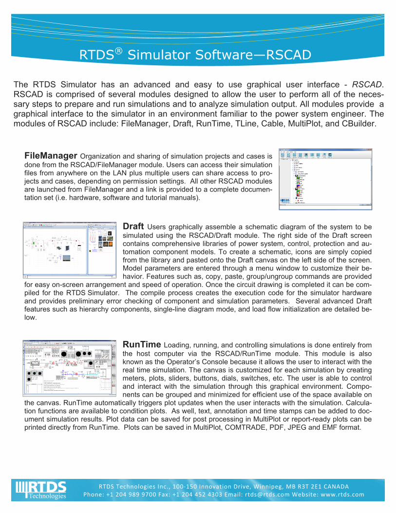
FileManager Organization and sharing of simulation projects and cases is done from the RSCAD/FileManager module. Users can access their simulation files from anywhere on the LAN plus multiple users can share access to pro-jects and cases, depending on permission settings. All other RSCAD modules are launched from FileManager and a link is provided to a complete documen-tation set (i.e. hardware, software and tutorial manuals).
Draft Users graphically assemble a schematic diagram of the system to be simulated using the RSCAD/Draft module. The right side of the Draft screen contains comprehensive libraries of power system, control, protection and au-tomation component models. To create a schematic, icons are simply copied from the library and pasted onto the Draft canvas on the left side of the screen. Model parameters are entered through a menu window to customize their be-havior. Features such as, copy, paste, group/ungroup commands are provided
for easy on-screen arrangement and speed of operation. Once the circuit drawing is completed it can be com-piled for the RTDS Simulator. The compile process creates the execution code for the simulator hardware and provides preliminary error checking of component and simulation parameters. Several advanced Draft features such as hierarchy components, single-line diagram mode, and load flow initialization are detailed be-low.
RunTime Loading, running, and controlling simulations is done entirely from the host computer via the RSCAD/RunTime module. This module is also known as the Operator’s Console because it allows the user to interact with the real time simulation. The canvas is customized for each simulation by creating meters, plots, sliders, buttons, dials, switches, etc. The user is able to control and interact with the simulation through this graphical environment. Compo-nents can be grouped and minimized for efficient use of the space available on
the canvas. RunTime automatically triggers plot updates when the user interacts with the simulation. Calcula-tion functions are available to condition plots. As well, text, annotation and time stamps can be added to doc-ument simulation results. Plot data can be saved for post processing in MultiPlot or report-ready plots can be printed directly from RunTime. Plots can be saved in MultiPlot, COMTRADE, PDF, JPEG and EMF format.
RTDS Technologies Inc., 100‐150 Innovation Drive, Winnipeg, MB R3T 2E1 CANADA Phone: +1 204 989 9700 Fax: +1 204 452 4303 Email: [email protected] Website: www.rtds.com

REAL T IME D IG ITAL S IMULAT ION FOR THE POWER INDUSTRY
RTDS Technologies Inc., 100‐150 Innovation Drive, Winnipeg, MB R3T 2E1 CANADA
TLine Physical AC and DC transmission line data is entered into the RSCAD/TLine module that converts it into a form usable in the circuit assem-bly module (RSCAD/Draft). Parameter for both Bergeron and frequency de-pendent traveling wave models can be calculated. Alternatively the line se-quence impedance data can be used to generate Bergeron line data.
Cable Similar to the RSCAD/TLine module, the RSCAD/Cable module pro-vides the conversion of physical cable data into a form usable in the RSCAD/Draft module. Both Bergeron and Frequency data can be generated.
CBuilder Occasionally advanced users want to implement customized components and run them in real time on the RTDS Simulator. The RSCAD/CBuilder module facilitates this by providing an environment in which the us-er draws the icon for the new component, defines the parameters, the input/output nodes and writes the code. The code for CBuilder components is based on ANSI C.
MultiPlot Advanced data analysis, conditioning, and plotting functions are available in RSCAD/MultiPlot for post-processing, analysis and printing of re-sults captured from the RTDS Simulator. Data can also be exported for post processing in other application software (Matlab, Mathcad, Excel, etc.)
Additional Features Automated batch operation makes it possible to run a series of simula-tions completely without user interaction. A script file can be created by record/replay, or through an editor, to describe a sequence of events (starting/stopping cases, initiating events, changing setpoints, saving re-sults, printing, etc.). Even circuit parameters can be changed through the use of Draft Variables. Therefore thousands of cases can be run and a summary report created without the need for user interaction.
Single line diagram (SLD) format in Draft provides the flexibility to toggle between single line or three-phase format for viewing and printing. The SLD viewing mode provides an easy to understand circuit overview while the three-phase mode allows details such as unsymmetrical loading to be im-plemented. Load-flow initialization provides the ability to calculate the load-flow for the Draft circuit prior to starting the simulation. By first initializing the simulation, the start up transient is minimized. Hierarchy allows portions of a Draft circuit to be collapsed into a hierarchy box. Multiple RSCAD Software Installations can be placed on any number of computers at a customer site. This allows different groups to work on real time simulation, circuit construction, post-processing, etc. all at the same time. SCD Editor embedded in the RSCAD software suite can used to edit/create the SCL files necessary to configure the IEC 61850 communication
RTDS Simulator Software
Power and Control System Component Libraries
The RSCAD/Draft module allows the user to assemble power system and/or control system component icons to create the desired simulation circuit. Compilers automatically generate the low-level code necessary to perform the simulation using the RTDS hardware. The low-level code in turn determines the function of the processors for each simulation.
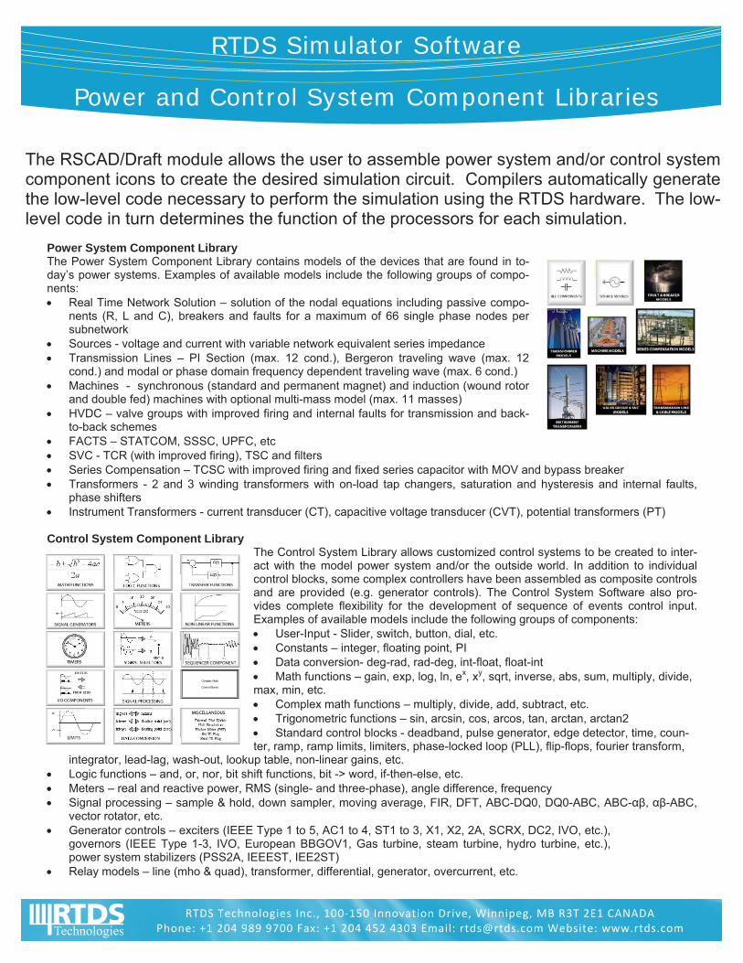
Power System Component Library The Power System Component Library contains models of the devices that are found in to-day’s power systems. Examples of available models include the following groups of compo-nents: Real Time Network Solution – solution of the nodal equations including passive compo-
nents (R, L and C), breakers and faults for a maximum of 66 single phase nodes per subnetwork
Sources - voltage and current with variable network equivalent series impedance Transmission Lines – PI Section (max. 12 cond.), Bergeron traveling wave (max. 12
cond.) and modal or phase domain frequency dependent traveling wave (max. 6 cond.) Machines - synchronous (standard and permanent magnet) and induction (wound rotor
and double fed) machines with optional multi-mass model (max. 11 masses) HVDC – valve groups with improved firing and internal faults for transmission and back-
to-back schemes FACTS – STATCOM, SSSC, UPFC, etc SVC - TCR (with improved firing), TSC and filters Series Compensation – TCSC with improved firing and fixed series capacitor with MOV and bypass breaker Transformers - 2 and 3 winding transformers with on-load tap changers, saturation and hysteresis and internal faults,
phase shifters Instrument Transformers - current transducer (CT), capacitive voltage transducer (CVT), potential transformers (PT) Control System Component Library
The Control System Library allows customized control systems to be created to inter-act with the model power system and/or the outside world. In addition to individual control blocks, some complex controllers have been assembled as composite controls and are provided (e.g. generator controls). The Control System Software also pro-vides complete flexibility for the development of sequence of events control input. Examples of available models include the following groups of components: User-Input - Slider, switch, button, dial, etc. Constants – integer, floating point, PI Data conversion- deg-rad, rad-deg, int-float, float-int Math functions – gain, exp, log, ln, ex, xy, sqrt, inverse, abs, sum, multiply, divide, max, min, etc. Complex math functions – multiply, divide, add, subtract, etc. Trigonometric functions – sin, arcsin, cos, arcos, tan, arctan, arctan2 Standard control blocks - deadband, pulse generator, edge detector, time, coun-ter, ramp, ramp limits, limiters, phase-locked loop (PLL), flip-flops, fourier transform,
integrator, lead-lag, wash-out, lookup table, non-linear gains, etc. Logic functions – and, or, nor, bit shift functions, bit -> word, if-then-else, etc. Meters – real and reactive power, RMS (single- and three-phase), angle difference, frequency Signal processing – sample & hold, down sampler, moving average, FIR, DFT, ABC-DQ0, DQ0-ABC, ABC-αβ, αβ-ABC,
vector rotator, etc. Generator controls – exciters (IEEE Type 1 to 5, AC1 to 4, ST1 to 3, X1, X2, 2A, SCRX, DC2, IVO, etc.),
governors (IEEE Type 1-3, IVO, European BBGOV1, Gas turbine, steam turbine, hydro turbine, etc.), power system stabilizers (PSS2A, IEEEST, IEE2ST)
Relay models – line (mho & quad), transformer, differential, generator, overcurrent, etc.
RTDS Technologies Inc., 100‐150 Innovation Drive, Winnipeg, MB R3T 2E1 CANADA Phone: +1 204 989 9700 Fax: +1 204 452 4303 Email: [email protected] Website: www.rtds.com

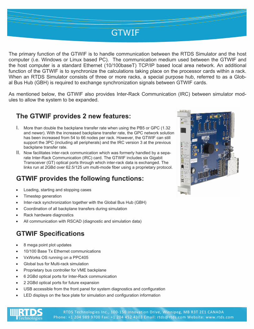
GTWIF
The primary function of the GTWIF is to handle communication between the RTDS Simulator and the host computer (i.e. Windows or Linux based PC). The communication medium used between the GTWIF and the host computer is a standard Ethernet (10/100baseT) TCP/IP based local area network. An additional function of the GTWIF is to synchronize the calculations taking place on the processor cards within a rack. When an RTDS Simulator consists of three or more racks, a special purpose hub, referred to as a Glob-al Bus Hub (GBH) is required to exchange synchronization signals between GTWIF cards. As mentioned below, the GTWIF also provides Inter-Rack Communication (IRC) between simulator mod-ules to allow the system to be expanded.
The GTWIF provides 2 new features:
I. More than double the backplane transfer rate when using the PB5 or GPC (1.32 and newer). With the increased backplane transfer rate, the GPC network solution has been increased from 54 to 66 nodes per rack. However, the GTWIF can still support the 3PC (including all peripherals) and the IRC version 3 at the previous backplane transfer rate.
II. Now facilitates inter-rack communication which was formerly handled by a sepa-rate Inter-Rack Communication (IRC) card. The GTWIF includes six Gigabit Transceiver (GT) optical ports through which inter-rack data is exchanged. The links run at 2GBd over 62.5/125 um multi-mode fiber using a proprietary protocol.
GTWIF provides the following functions:
Loading, starting and stopping cases
Timestep generation
Inter-rack synchronization together with the Global Bus Hub (GBH)
Coordination of all backplane transfers during simulation
Rack hardware diagnostics
All communication with RSCAD (diagnostic and simulation data)
GTWIF Specifications
8 mega point plot updates
10/100 Base Tx Ethernet communications
VxWorks OS running on a PPC405
Global bus for Multi-rack simulation
Proprietary bus controller for VME backplane
6 2GBd optical ports for Inter-Rack communication
2 2GBd optical ports for future expansion
USB accessible from the front panel for system diagnostics and configuration
LED displays on the face plate for simulation and configuration information
RTDS Technologies Inc., 100‐150 Innovation Drive, Winnipeg, MB R3T 2E1 CANADA Phone: +1 204 989 9700 Fax: +1 204 452 4303 Email: [email protected] Website: www.rtds.com

PB5 Processor Card
The PB5 processor card is the latest generation of processor cards developed for the RTDS Simulator. New simulators are being based exclusively on PB5 processor cards. The PB5 is also fully compatible with the GPC processor card and can be used to up-grade and enhance the capabilities of existing GTWIF – GPC based simulators. Each PB5 has two PowerPC RISC processors operating at a clock frequency of 1.7 GHz. The increased clock frequency provides increased computing capacity compared to the GPC card. One of the other significant new features provided by the PB5 is that it has eight (8) GT fibre ports. Two (2) GT ports are reserved for connecting to I/O and the other six (6) ports can be used to communicate directly to other PB5 or GPC cards.
Comparison of PB5 versus GPC Processor Cards:
The table below provides a comparison overview for the new PB5 processor card versus the GPC processor card. The PB5 is the latest processor card to be developed by RTDS Tech-nologies and it offers a number of benefits and features compared to the GPC card. The most significant advancements are the following:
The PB5 provides 12 load units per processor compared to 10 for the GPC card. The additional load units allow more components to be included on one PB5 processor.
The maximum number of nodes in a single network solution has been increased on the PB5 to 72 single-phase nodes (24 three-phase buses) from 66 single-phase nodes on the GPC card.
With the PB5 card two network solutions can be included in one rack. Therefore two subsystems with 72 nodes each can be included on one rack. With the GPC card only one network solution was allowed per rack.
The PB5 card has 6 communication ports to allow direct communication to other PB5 cards. The GPC had only 2 communication ports for direct communication to other processor cards. The additional communication ports on the PB5 card make it easier to model large scale systems using Small Timestep Subnetworks which can be a big ad-vantage for modeling distribution level systems.
RTDS Technologies Inc., 100‐150 Innovation Drive, Winnipeg, MB R3T 2E1 CANADA Phone: +1 204 989 9700 Fax: +1 204 452 4303 Email: [email protected] Website: www.rtds.com
Card Type PB5 GPC
Year of Production 2011 2005
Processor type Freescale - MC7448 RISC IBM - 750GX RISC
Clock speed 1.7 GHz 1.0 GHz
No. of processors per card 2 2
Load units per processor 12 10
Network solution (max nodes) 72 x 2 = 144 * 66
No. of I/O fibre ports 2 2
No. of comm. Ports 6 2
No. of 12 bit d/a’s 24 24
Advanced Features One of the main motivators for developing the PB5 pro-cessor card was to increase the direct card-to-card com-munication capabilities. The additional communication ports allow many small timestep subnetworks to be inter-connected using traveling wave models and therefore significantly increase the size of the network implemented in the small timestep domain.
Exchange program Customers covered under the extended warranty and maintenance program will benefit from the option to ex-change old processor cards to receive a 50% reduction in the purchase price of PB5 cards.
GTNET
RTDS Technologies has developed the GTNET to provide real time communication to and from the Simu-lator via Ethernet. Different firmware versions are used with the GTNET depending on the application. The different firmware versions, described below in detail, accommodate IEC 61850 GSE binary messag-ing, IEC 61850-9-2 sampled values, playback of large data files stored on a PC hard disk, and DNP com-munication.
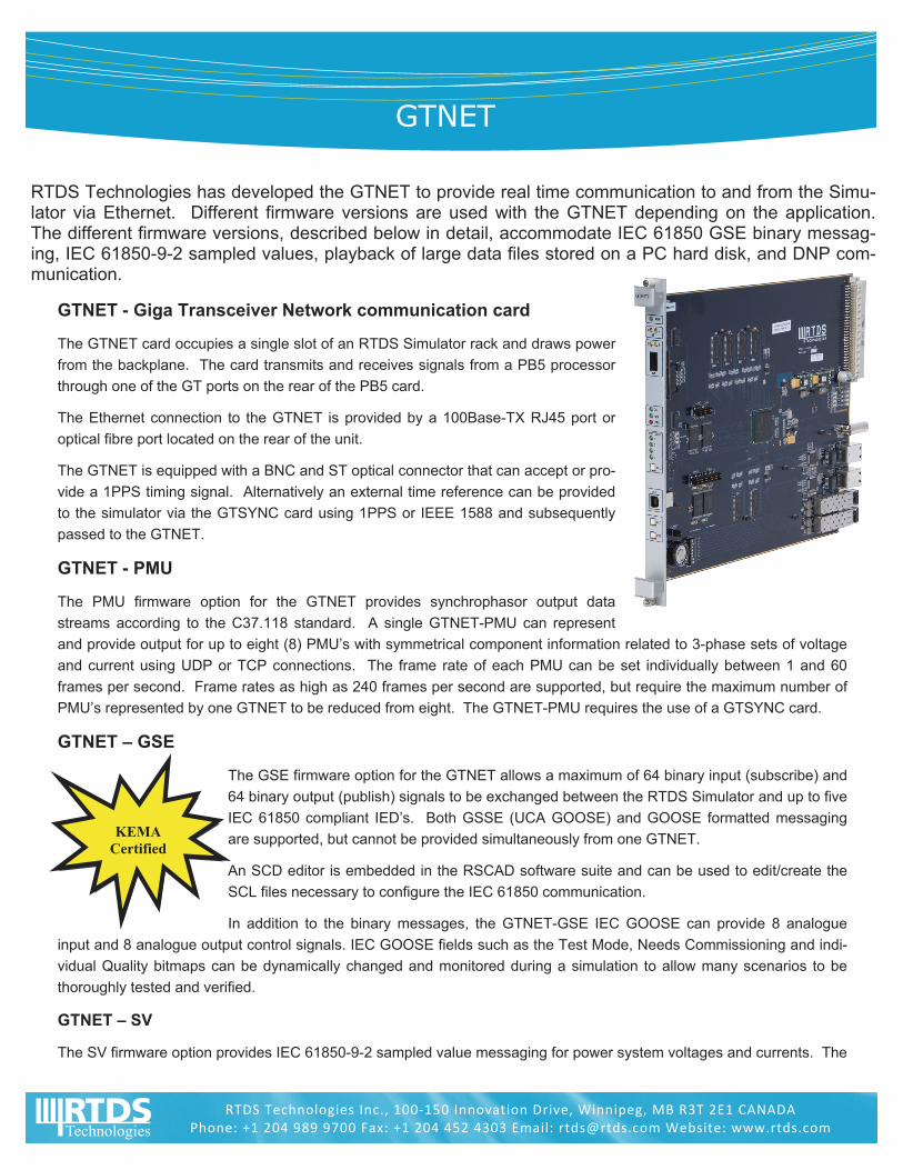
GTNET - Giga Transceiver Network communication card
The GTNET card occupies a single slot of an RTDS Simulator rack and draws power
from the backplane. The card transmits and receives signals from a PB5 processor
through one of the GT ports on the rear of the PB5 card.
The Ethernet connection to the GTNET is provided by a 100Base-TX RJ45 port or
optical fibre port located on the rear of the unit.
The GTNET is equipped with a BNC and ST optical connector that can accept or pro-
vide a 1PPS timing signal. Alternatively an external time reference can be provided
to the simulator via the GTSYNC card using 1PPS or IEEE 1588 and subsequently
passed to the GTNET.
GTNET - PMU
The PMU firmware option for the GTNET provides synchrophasor output data
streams according to the C37.118 standard. A single GTNET-PMU can represent
and provide output for up to eight (8) PMU’s with symmetrical component information related to 3-phase sets of voltage
and current using UDP or TCP connections. The frame rate of each PMU can be set individually between 1 and 60
frames per second. Frame rates as high as 240 frames per second are supported, but require the maximum number of
PMU’s represented by one GTNET to be reduced from eight. The GTNET-PMU requires the use of a GTSYNC card.
GTNET – GSE
The GSE firmware option for the GTNET allows a maximum of 64 binary input (subscribe) and
64 binary output (publish) signals to be exchanged between the RTDS Simulator and up to five
IEC 61850 compliant IED’s. Both GSSE (UCA GOOSE) and GOOSE formatted messaging
are supported, but cannot be provided simultaneously from one GTNET.
An SCD editor is embedded in the RSCAD software suite and can be used to edit/create the
SCL files necessary to configure the IEC 61850 communication.
In addition to the binary messages, the GTNET-GSE IEC GOOSE can provide 8 analogue
input and 8 analogue output control signals. IEC GOOSE fields such as the Test Mode, Needs Commissioning and indi-
vidual Quality bitmaps can be dynamically changed and monitored during a simulation to allow many scenarios to be
thoroughly tested and verified.
GTNET – SV
The SV firmware option provides IEC 61850-9-2 sampled value messaging for power system voltages and currents. The
RTDS Technologies Inc., 100‐150 Innovation Drive, Winnipeg, MB R3T 2E1 CANADA Phone: +1 204 989 9700 Fax: +1 204 452 4303 Email: [email protected] Website: www.rtds.com
KEMA
Certified
REAL T IME D IG ITAL S IMULAT ION FOR THE POWER INDUSTRY
RTDS Technologies Inc., 100‐150 Innovation Drive, Winnipeg, MB R3T 2E1 CANADA Phone: +1 204 989 9700 Fax: +1 204 452 4303 Email: [email protected] Website: www.rtds.com
GTNET-SV can either publish or subscribe to sampled value data streams. In order to timestamp the sampled values, a
one pulse per second (1PPS) signal can be input to the GTNET via a BNC or ST optical connection.
When used with a GTSYNC card, one GTNET card can simultaneously publish two sampled value output data streams
each with a maximum of eight signals (e.g. 4 x V and 4 x I) and at a rate of 80 samples per cycle. It is also possible to
publish one data stream at a rate of 256 samples per cycle.
When used for sampled value input, the GTNET-SV can subscribe to one IEC 61850-9-2 LE data stream (e.g. 4 x V and
4 x I) at 80 samples per cycle.
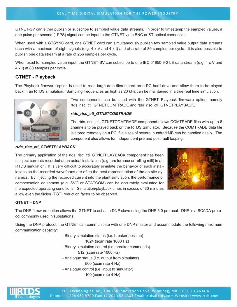
GTNET - Playback
The Playback firmware option is used to read large data files stored on a PC hard drive and allow them to be played
back in an RTDS simulation. Sampling frequencies as high as 20 kHz can be maintained in a true real time simulation.
Two components can be used with the GTNET Playback firmware option, namely
rtds_risc_ctl_GTNETCOMTRADE and rtds_risc_ctl_GTNETPLAYBACK.
rtds_risc_ctl_GTNETCOMTRADE
The rtds_risc_ctl_GTNETCOMTRADE component allows COMTRADE files with up to 8
channels to be played back on the RTDS Simulator. Because the COMTRADE data file
is stored remotely on a PC, file sizes of several hundred MB can be handled easily. The
component also allows for independent pre and post fault looping.
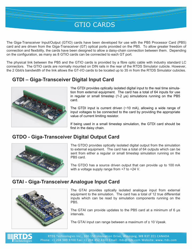
rtds_risc_ctl_GTNETPLAYBACK
The primary application of the rtds_risc_ctl_GTNETPLAYBACK component has been
to inject currents recorded at an actual installation (e.g. arc furnace or rolling mill) in an
RTDS simulation. It is very difficult to accurately simulate the behavior of such instal-
lations so the recorded waveforms are often the best representation of the on site dy-
namics. By injecting the recorded current into the plant simulation, the performance of
compensation equipment (e.g. SVC or STATCOM) can be accurately evaluated for
the expected operating conditions. Simulation/playback times in excess of 30 minutes
allow even the flicker (PST) reduction factor to be observed.
GTNET – DNP
The DNP firmware option allows the GTNET to act as a DNP slave using the DNP 3.0 protocol. DNP is a SCADA proto-
col commonly used in substations.
Using the DNP protocol, the GTNET can communicate with one DNP master and accommodate the following maximum
communication capacity:
- Binary simulation status (i.e. breaker position)
1024 (scan rate 1000 Hz)
- Binary simulation control (i.e. breaker commands)
512 (scan rate 1000 Hz)
- Analogue status (i.e. output from simulator)
500 (scan rate 4 Hz)
- Analogue control (i.e. input to simulator)
100 (scan rate 4 Hz)
GTIO CARDS
The Giga-Transceiver Input/Output (GTIO) cards have been developed for use with the PB5 Processor Card (PB5) card and are driven from the Giga-Transceiver (GT) optical ports provided on the PB5. To allow greater freedom of connection and flexibility, the cards have been designed to allow a daisy-chain connection between them. Depending on the configuration, as many as 8 GTIO cards can be connected to each GT port. The physical link between the PB5 and the GTIO cards is provided by a fibre optic cable with industry standard LC connectors. The GTIO cards are normally mounted on DIN rails in the rear of the RTDS Simulator cubicle. However, the 2 Gbit/s bandwidth of the link allows the GT-I/O cards to be located up to 35 m from the RTDS Simulator cubicles.
GTDI – Giga-Transceiver Digital Input Card
The GTDI provides optically isolated digital input to the real time simula-tion from external equipment. The card has a total of 64 inputs for use in regular or small timestep (1-2 μs) simulations running on the PB5 card. The GTDI input is current driven (~10 mA), allowing a wide range of input voltages to be connected to the card by providing the appropriate value of current limiting resistor. If being used in a small timestep simulation, the GTDI card should be first in the daisy chain.
GTDO - Giga-Transceiver Digital Output Card
The GTDO provides optically isolated digital output from the simulation to external equipment. The card has a total of 64 outputs which can be sent from either a regular or small timestep simulation running on the PB5 card. The GTDO has a source driven output that can provide up to 100 mA with a voltage supply range from +7 to +24 V.
GTAI - Giga-Transceiver Analogue Input Card
The GTAI provides optically isolated analogue input from external equipment to the simulation. The card has a total of 12 true differential inputs which can be read by simulation components running on the PB5. The GTAI can provide updates to the PB5 card at a minimum of 6 μs intervals. The GTAI input can range between a maximum of ± 10 Vpeak.
RTDS Technologies Inc., 100‐150 Innovation Drive, Winnipeg, MB R3T 2E1 CANADA Phone: +1 204 989 9700 Fax: +1 204 452 4303 Email: [email protected] Website: www.rtds.com
REAL T IME D IG ITAL S IMULAT ION FOR THE POWER INDUSTRY
RTDS Technologies Inc., 100‐150 Innovation Drive, Winnipeg, MB R3T 2E1 CANADA Phone: +1 204 989 9700 Fax: +1 204 452 4303 Email: [email protected] Website: www.rtds.com
GTAO - Giga-Transceiver Analogue Output Card
The GTAO provides optically isolated analogue output from the simula-tion to external equipment. The card has a total of 12 outputs which can be sent from either regular or small timestep simulations running on the PB5. Special care has been taken in the design of the GTAO to provide the communication bandwidth required for small timestep applications. The GTAO output can range between a maximum of ± 10 Vpeak. When operating with a regular timestep simulation, the GTAO card can provide oversampling of the output at 1.0 μs intervals.
GTFPI – Giga-Transceiver Front Panel Interface Card
The GTFPI card is used to read and write signals between the front panel and the RTDS Simulator. The GTFPI can be used with both the TTL level digital I/O panel and the dry contact (high voltage) panel. Data exchange between the front panels and the GTFPI is via a ribbon cable, while the data exchange between the GTFPI and PB5 is via a GT port.
GTSYNC – Giga-Transceiver Synchronization Card
The GTSYNC card is used to synchronize the RTDS simulation timestep to an external time reference (eg. GPS clock) and to synchro-nize devices under test. The GSYNC connects to the GT port on the GTWIF and cannot be daisy chained to other I/O cards. The GTSYNC supports 1 Pulse Per Second (1PPS) over BNC coax or ST type fibre connectors, IEEE 1588 over RJ45 or ST fibre connectors as well as IRIG-B over a BNC coax connection. Synchronization of the simulation timestep to an external time reference is necessary for PMU benchmark testing and it is advantageous for IEC 61850-9-2 sampled value output.
RTDS Simulator
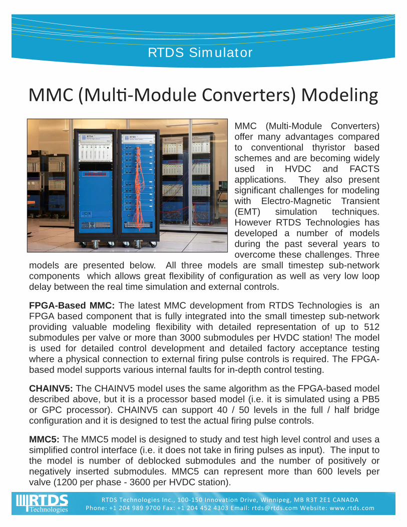
MMC (Multi-Module Converters)offer many advantages compared to conventional thyristor based schemes and are becoming widely used in HVDC and FACTS applications. They also present significant challenges for modeling with Electro-Magnetic Transient (EMT) simulation techniques. However RTDS Technologies has developed a number of models during the past several years to overcome these challenges. Three
models are presented below. All three models are small timestep sub-network components which allows great flexibility of configuration as well as very low loop delay between the real time simulation and external controls.
FPGA-Based MMC: The latest MMC development from RTDS Technologies is an FPGA based component that is fully integrated into the small timestep sub-network providing valuable modeling flexibility with detailed representation of up to 512 submodules per valve or more than 3000 submodules per HVDC station! The model is used for detailed control development and detailed factory acceptance testing where a physical connection to external firing pulse controls is required. The FPGA-based model supports various internal faults for in-depth control testing.
CHAINV5: The CHAINV5 model uses the same algorithm as the FPGA-based model described above, but it is a processor based model (i.e. it is simulated using a PB5 or GPC processor). CHAINV5 can support 40 / 50 levels in the full / half bridge configuration and it is designed to test the actual firing pulse controls.
MMC5: The MMC5 model is designed to study and test high level control and uses a simplified control interface (i.e. it does not take in firing pulses as input). The input to the model is number of deblocked submodules and the number of positively or negatively inserted submodules. MMC5 can represent more than 600 levels per valve (1200 per phase - 3600 per HVDC station).
RTDS Technologies Inc., 100‐150 Innovation Drive, Winnipeg, MB R3T 2E1 CANADA Phone: +1 204 989 9700 Fax: +1 204 452 4303 Email: [email protected] Website: www.rtds.com
MMC (Mul ‐Module Converters) Modeling
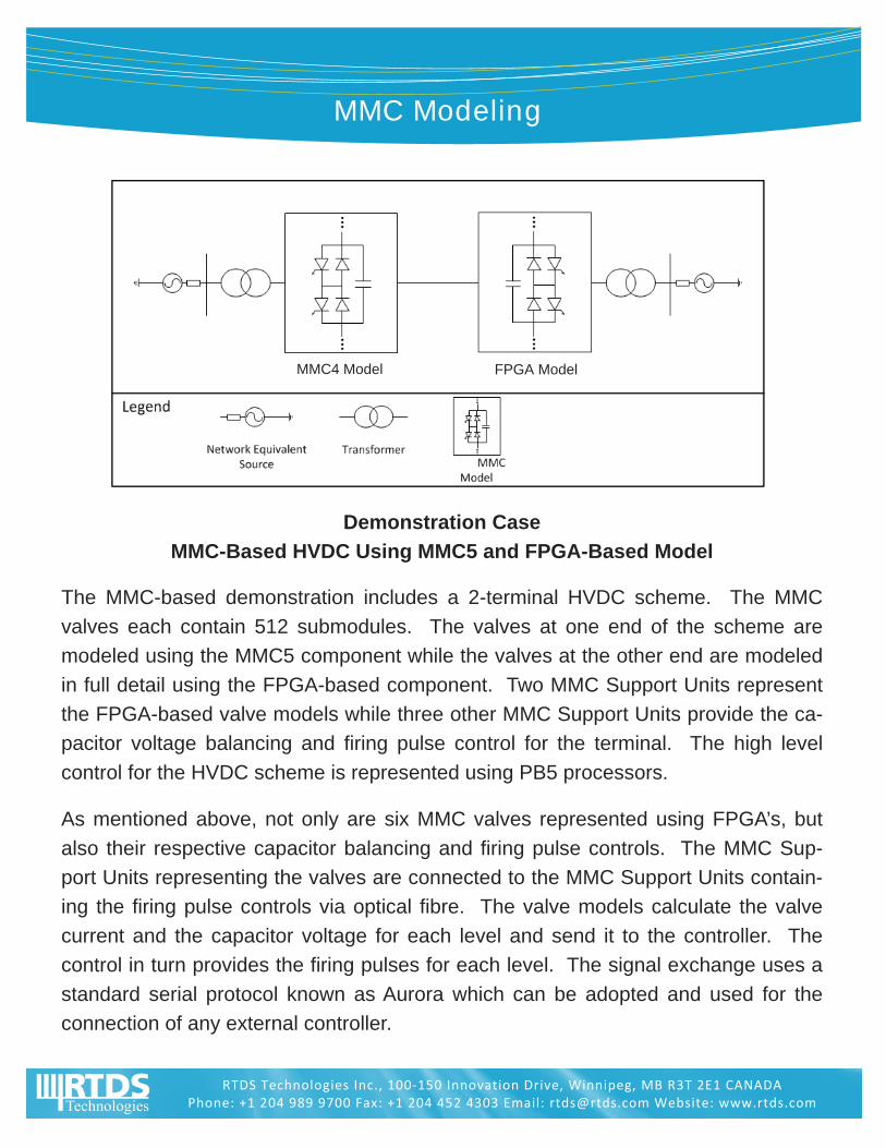
MMC Modeling
Demonstration Case
MMC-Based HVDC Using MMC5 and FPGA-Based Model
The MMC-based demonstration includes a 2-terminal HVDC scheme. The MMC
valves each contain 512 submodules. The valves at one end of the scheme are
modeled using the MMC5 component while the valves at the other end are modeled
in full detail using the FPGA-based component. Two MMC Support Units represent
the FPGA-based valve models while three other MMC Support Units provide the ca-
pacitor voltage balancing and firing pulse control for the terminal. The high level
control for the HVDC scheme is represented using PB5 processors.
As mentioned above, not only are six MMC valves represented using FPGA’s, but
also their respective capacitor balancing and firing pulse controls. The MMC Sup-
port Units representing the valves are connected to the MMC Support Units contain-
ing the firing pulse controls via optical fibre. The valve models calculate the valve
current and the capacitor voltage for each level and send it to the controller. The
control in turn provides the firing pulses for each level. The signal exchange uses a
standard serial protocol known as Aurora which can be adopted and used for the
connection of any external controller.
RTDS Technologies Inc., 100‐150 Innovation Drive, Winnipeg, MB R3T 2E1 CANADA Phone: +1 204 989 9700 Fax: +1 204 452 4303 Email: [email protected] Website: www.rtds.com
MMC4 Model FPGA Model
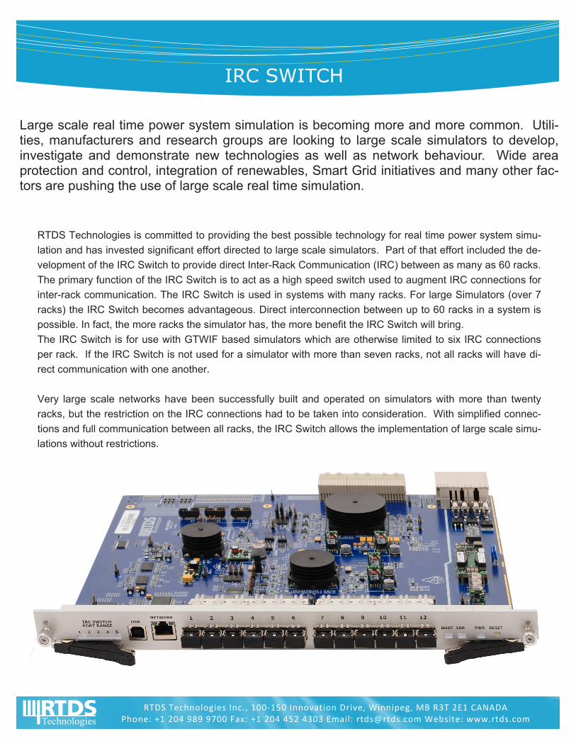
IRC SWITCH
Large scale real time power system simulation is becoming more and more common. Utili-ties, manufacturers and research groups are looking to large scale simulators to develop, investigate and demonstrate new technologies as well as network behaviour. Wide area protection and control, integration of renewables, Smart Grid initiatives and many other fac-tors are pushing the use of large scale real time simulation.
RTDS Technologies is committed to providing the best possible technology for real time power system simu-
lation and has invested significant effort directed to large scale simulators. Part of that effort included the de-
velopment of the IRC Switch to provide direct Inter-Rack Communication (IRC) between as many as 60 racks.
The primary function of the IRC Switch is to act as a high speed switch used to augment IRC connections for
inter-rack communication. The IRC Switch is used in systems with many racks. For large Simulators (over 7
racks) the IRC Switch becomes advantageous. Direct interconnection between up to 60 racks in a system is
possible. In fact, the more racks the simulator has, the more benefit the IRC Switch will bring.
The IRC Switch is for use with GTWIF based simulators which are otherwise limited to six IRC connections
per rack. If the IRC Switch is not used for a simulator with more than seven racks, not all racks will have di-
rect communication with one another.
Very large scale networks have been successfully built and operated on simulators with more than twenty
racks, but the restriction on the IRC connections had to be taken into consideration. With simplified connec-
tions and full communication between all racks, the IRC Switch allows the implementation of large scale simu-
lations without restrictions.
RTDS Technologies Inc., 100‐150 Innovation Drive, Winnipeg, MB R3T 2E1 CANADA Phone: +1 204 989 9700 Fax: +1 204 452 4303 Email: [email protected] Website: www.rtds.com

REAL T IME D IG ITAL S IMULAT ION FOR THE POWER INDUSTRY
RTDS Technologies Inc., 100‐150 Innovation Drive, Winnipeg, MB R3T 2E1 CANADA Phone: +1 204 989 9700 Fax: +1 204 452 4303 Email: [email protected] Website: www.rtds.com
The IRC Switch provides several benefits over GTWIF and previous generation IRC connected systems
Greater connectivity: Without the IRC Switch, each rack can directly communicate with up to 6 other
racks. The IRC Switch provides full interconnection between all racks on systems up to 60 racks.
Greater flexibility: Without the IRC Switch, on systems greater than 7 racks care must be taken to ensure
proper rack connections. The user has to know which racks are connected together while building their
case. With the IRC Switch, each rack can communicate directly with all the other racks in the system, sim-
plifying case building.
Simplified wiring: Instead of up to 6 connections per rack to other racks, the IRC Switch requires only one
fiber connection per rack to it, allowing for easy setup of larger systems. For example, in a 30 rack sys-
tem, 30x6 = 180 connections were required to 30 different locations. With the IRC Switch, only 30 coN-
nections are required and they are all routed to one location.
IRC Switch Specifications
12 to 60 communication ports (1 to 5 cards)
Each port communicates at 2GBd using 62.5/125 µm multi-mode fiber
Fully bi-directional interconnect between all racks in a simulation
Broadcast capability allows a rack to transmit a packet to all potential receiving racks
Housed in a mid-size cubicle together with the Global Bus Hub
RTDS Simulator
The RTDS® Simulator is a real time power system simulator widely used for closed-loop testing of physical protection and control equipment. For over 15 years now conventional protection equipment has been tested by driving power amplifiers (voltage and/or current) from the simulator’s analogue output channels and by reading back the status of contacts for trip, reclose and other miscellaneous elements. Since the simulator operates in true real time, the protection equipment and the response of the simulated network are just as they would be in the real system. For example if a fault simulated in the network results in a trip being issued by the protection, a breaker in the simulated network will be opened and the subsequent voltages and currents affected correspondingly. The closed-loop response of the real time simulator also allows multiple relays to be connected simultaneously so their interaction can be evaluated. To address the testing of IEC 61850 compliant protection equipment, RTDS Technologies has developed the GTNET card. Depending on the active protocol, the GTNET card can provide IEC 61850 GOOSE messaging or IEC 61850-9-2 sampled values for voltage and current.
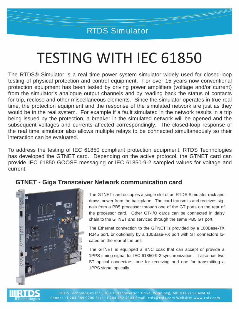
GTNET - Giga Transceiver Network communication card
The GTNET card occupies a single slot of an RTDS Simulator rack and
draws power from the backplane. The card transmits and receives sig-
nals from a PB5 processor through one of the GT ports on the rear of
the processor card. Other GT-I/O cards can be connected in daisy
chain to the GTNET and serviced through the same PB5 GT port.
The Ethernet connection to the GTNET is provided by a 100Base-TX
RJ45 port, or optionally by a 100Base-FX port with ST connectors lo-
cated on the rear of the unit.
The GTNET is equipped a BNC coax that can accept or provide a
1PPS timing signal for IEC 61850-9-2 synchronization. It also has two
ST optical connectors, one for receiving and one for transmitting a
1PPS signal optically.
RTDS Technologies Inc., 100‐150 Innovation Drive, Winnipeg, MB R3T 2E1 CANADA Phone: +1 204 989 9700 Fax: +1 204 452 4303 Email: [email protected] Website: www.rtds.com
TESTING WITH IEC 61850
REAL T IME D IG ITAL S IMULAT ION FOR THE POWER INDUSTRY
RTDS Technologies Inc., 100‐150 Innovation Drive, Winnipeg, MB R3T 2E1 CANADA Phone: +1 204 989 9700 Fax: +1 204 452 4303 Email: [email protected] Website: www.rtds.com
GTNET – GSE for IEC 61850 GOOSE Messaging
The GTNET-GSE firmware option for the GTNET card can be used to model 1-4 individual IEDs
(Intelligent Electronic Devices). Each model is capable of sending and receiving up to 64 points (or
32 points with associated quality bitmap). For each GTNET card, GOOSE messages can be re-
ceived from a total of 16 unique external IEDs. The GTNET GOOSE configuration is done via an
SCD file. RSCAD contains a built in SCD editor which helps the user to easily and conveniently
configure the publication and subscription of GOOSE messages.
IEC GOOSE fields such as the Test mode, Needs Commissioning and individual Quality bitmaps
can be dynamically changed and monitored for both transmit and receive messages during a simu-
lation to allow many scenarios to be thoroughly tested and verified. The GOOSE messaging provid-
ed by the GTNET card is KEMA certified.
GTNET – SV for IEC 61850-9-2 Sampled Value Messaging
The SV firmware option provides IEC 61850-9-2 sampled value messaging for power system volt-
ages and currents. The GTSYNC card is used to synchronize the SV timestamps with an external
1PPS (one pulse-per-second), IEEE 1588, or IRIG-B signal from
a synchronized time source (ie. GPS clock). A 1PPS signal can
also be generated directly from the GTSYNC card.
Two data streams with up to 4 current and 4 voltage channels
each can be transmitted at a rate of 80 samples/cycle. Alterna-
tively, one data stream can be transmitted at 256 samples/cycle.
It is also possible to receive SV data from one Merging Unit (4 currents
and 4 voltages) at either 80 or 256 samples/cycle.
Interoperability
The GTNET-GSE and GTNET–SV options have been successfully tested
with products from a number of different vendors. RTDS Technologies
has also demonstrated closed-loop testing that included IEC 61850
GOOSE messaging and sampled values with multiple vendor products in-
teroperating. RTDS Technologies has also participated in IEC 61850 Inter-
Operation events along with major protective relay manufacturers where
the RTDS Simulator and GTNET card were an integral part of the testing.
PORTABLE RTDS® SIMULATOR
The Portable RTDS Simulator uses the same proven hardware and software as the full-size RTDS Simulator, packaged in a compact cubicle that is easily picked up and moved from place to place. Like all RTDS Simulators, the Portable provides continuous real time electromagnetic transient simulation and can be used for conducting closed-loop testing of protection and control.
RTDS Technologies Inc., 100‐150 Innovation Drive, Winnipeg, MB R3T 2E1 CANADA Phone: +1 204 989 9700 Fax: +1 204 452 4303 Email: [email protected] Website: www.rtds.com
Simulation Capabilities The Portable is capable of simulating a variety of power systems. Some examples include the Cigre HVDC-SSR benchmark case with a 12-pulse monopolar system and controls, double-ended line protection test systems with twin circuit lines, sys-tems for testing generator controls, distributed gen-eration systems, etc. Seventy-two single-phase nodes can be included in the power systems. Dia-grams of these or other sample systems can be provided upon request.
Simulation Hardware The Portable has 7 card slots and that are typically populated with one Giga-Transceiver Workstation InterFace (GTWIF) card and three PB5 Processor Cards (PB5). Optionally, one PB5 can be removed and replaced by one or two GTNET cards to provide full IEC 61850 testing capability through the GTNET-GSE firmware option. Since the GTWIF card includes IRC channels, the Portable can be connected to other racks for larger network simulations. A GTFPI card is installed in the top drawer of all Portable cubicles and provides external access to low level digital inputs and outputs. An access hole is provided in the side of the Porta-ble cubicle to allow fibre optic connections to GTIO cards from PB5 cards and IRC connections from the GTWIF to other simulator racks.
Dimensions Weight ~ 40 lbs (18 kg) Dimensions 23” x 8 1/8” x 20” (58 cm x 21 cm x 51 cm)
REAL T IME D IG ITAL S IMULAT ION FOR THE POWER INDUSTRY
RTDS Technologies Inc., 100‐150 Innovation Drive, Winnipeg, MB R3T 2E1 CANADA Phone: +1 204 989 9700 Fax: +1 204 452 4303 Email: [email protected] Website: www.rtds.com
Portable I/O Cubicle
Due to the limited capability to mount GTIO
cards within the Portable cubicle (there is room
for one GTFPI card), a separate I/O cubicle
can be provided to house additional GTIO
cards. The portable I/O cubicle has a 24 V
power supply to run the GTIO cards and cast-
ers so that it can easily be moved from place
to place. A flight case is also available for the
portable I/O cubicle as an optional item.
The portable I/O cubicle contains two DIN rails
on which GTIO cards can be installed. The fol-
lowing GTIO cards can be installed in the port-
able I/O cubicle:
GTAO - (analogue output) optically isolated digital to analogue (d/a) converter card which provides 12 output
channels with 16-bit resolution.
GTAI - (analogue input) optically isolated analogue to digital (a/d) converter card
that provides 12 input channels with 16-bit resolution.
GTDO - (digital output) optically isolated card that provides 64 digital output
channels.
GTDI - (digital input) optically isolated card that provides 64 digital input chan-
nels.
GTSYNC - (synchronization card) time synchronization for 1PPS, IEEE 1588,
or IRIG-B
250 Vdc Digital Output Interface Panel - 16 dry contact outputs typically used
to send status signals (e.g. breaker status) to protection equipment at station
level voltages.
Dimensions
Weight ~ 53 lbs (24 kg) without High Voltage panel
~ 60 lbs (27kg) with High voltage panel
Dimensions 12” x 12” x 39” (31 cm x 31 cm x 99 cm)
Total DIN Rail Space 59” (150 cm)
RTDS Technologies Inc.
Worldwide Representatives
RTDS Technologies Inc., 100‐150 Innovation Drive, Winnipeg, MB R3T 2E1 CANADA Phone: +1 204 989 9700 Fax: +1 204 452 4303 Email: [email protected] Website: www.rtds.com
Australia Mr. Daniel Cetrola ADAPT Australia Pty. Ltd 11-19 Global Drive P. O. Box 1508 Tullamarine VIC 3043 AUSTRALIA
Telephone: + 61 3 9330 0666 Fax: +61 3 9330 0777 Email: [email protected]
Brazil Mr. Sylvio Cayres Cayres Pinto Engenharia Ltdª. Rua Ramon Franco, 104 - Urca Rio de Janeiro RJ 22290-290 BRAZIL
Telephone: + 55 21 2570 2051 Fax: + 55 21 2570 2051 Email: [email protected]
Czech Republic, Hungary, Italy Poland, Slovak Republic Dr. Paolo Sacchi Marcora S.r.l. Via Marcora 12 Milan 20121 ITALY
Telephone: +39 02 45482744 Fax: +39 02 99985643 Email: [email protected]
France Mr. Daniel Geha Éova Énergie 11, rue des Ternes Paris 75017 FRANCE
Telephone: + 33 9 60 36 26 77 Fax: + 33 1 72 70 31 74 Email: [email protected]
Germany Dr. Markus Pöller Moeller and Poeller Engineering GmbH Europaplatz 5 Tübingen 72072 GERMANY
Telephone: + 49 7071 13879-10 Fax: +49 7071 13879-99 Email: [email protected]
Greece Mr. Vassilis L. Georgiou PROT.A.S.I.S. S.A. Megaron Theseus, 46 El. Venizelou Ave. & 2 Frinis Str. Kallithea Attiki Hellas, Athens 176 76 GREECE
Telephone: + 30 210 9561 154 Fax: + 30 210 9561 164 Email: [email protected]
India Mr. Ramesh Kamat Nayak Power Systems Pvt. Ltd. 14/3, 2nd Floor, HRB Chambers Andree Road, Shanthi Nagar Bangalore, 560027 INDIA
Telephone: +91 804 094 5102 Fax: + 91 804 094 5102 Email: [email protected]
Indonesia Mr. Anton Santoso PT OKANSA INDONESIA Menara Sudirman 8th Floor Jl. Jend Sudirman Kav 60 Jakarta 12190 INDONESIA
Telephone: +62 21 522 6528 Fax: + 62 21 522 6517 Email: [email protected]
Japan Mr. Takahiro Horikoshi JP Business Service Corporation 2-2-18, Fukagawa, Koto-ku Tokyo 135-8451 JAPAN
Telephone: +81 3 3642 9771 Fax: + 81 3 3642 9796 Email: [email protected]
Malaysia Mr. Zulkifli Hj. Zahari ZET Corporation SDN. BHD. 9, Jalan SS7/10 Kelana Jaya Petaling Jaya Selangor Darul Ehsan 47301 MALAYSIA
Telephone: +603 7873 0784 / 0785 / 0786 Fax: + 603 7873 0769 Email: [email protected]
Mexico Mr. Samuel Ortiz de Ochoa Productos y Controles del Norte, S.A. de C.V. Oficina Monterrey Cipres 2611-B Colonia Moderna Monterrey, N.L. C.P. 64530 MEXICO
Telephone: + 52 81 8372 8921 / 8375 4207 Fax: + 52 81 8114 9962 Email: [email protected]
Middle East Mr. Reza Rabbani Rabbani Enterprise Ltd. 25 Castor Crescent Toronto, ON M1G 3R1 CANADA
Telephone: +416 438 4198 Fax: + 416 438 8202 Email: [email protected]
Philippines Sunertech 2/F The Victoria Plaza 41 Annapolis Street, Greenhills San Juan City 1502 PHILIPPINES
Telephone: +63 2 724-7203 / 725-0465 Fax: + 63 2 721-2271 Email: [email protected] Email: [email protected]
Russian Federation Mr. Janez Zakonjsek ENLAB cjsc Ul. Nizhegorodskaya d. 4, Office 101/2 428018 Cheboksary Chuvash Republic RUSSIAN FEDERATION
Telephone: +7 8352 406626 Email: [email protected]
Singapore, Vietnam Mr. David Chong Precision Technologies PTE LTD. 211 Henderson Road # 13-02 Henderson Industrial Park Singapore 159552 SINGAPORE
Telephone: +65 6 758 9785 Fax: + 65 6 273 8898 Email: [email protected]
South Africa and Namibia Mr. Alexander Dierks etalumiSe P.O. Box 26 120 Hout Bay 7872 SOUTH AFRICA
Telephone: +27 21 790 1665 Fax: + 27 21 790 0708 Email: [email protected]
Spain and Portugal Mr. Vicente Aucejo Ingenieria de Diseno Electrotecnico, S.L. Pol. Ind. Moncada II –Pont Sec, 5 46113-Moncada SPAIN
Telephone: +34 96 1303462 Fax: +34 96 130 91 67 Email: [email protected]
Taiwan Mr. Nelson Lai Metrologies Enterprise Co., Ltd. 8F, No. 30, Sec. 1, Min-Sheng E. Rd., Taipei TAIWAN, R.O.C
Telephone: +886 2 2561 5572/25373650 Fax: + 886 2 2537 6602 Email: [email protected]
Thailand Mr. Thanachat Thanasettagone Unipower Engineering Co., Ltd. 12 Thetsabannimittai Road Ladyao Chatuchak Bankok 10900 THAILAND
Telephone : + 622 953 8020 Fax : + 622 953 8024 Email : [email protected]
United States Dr. Omprakash Nayak Nayak Corporation 475 Wall Street Princeton, New Jersey 08540 USA
Telephone: +609 279 9050 Fax: + 609 279 9051 Email: [email protected]
Venezuela Sr. Ernesto Camacho Power Quality C.A. PO Box 14.234 Edf. Centro Parque Carabobo, piso 9, oficina 9-11, Av Universidad, La Candelaria Caracas 1011-A VENEZUELA
Telephone: +58 212 576 0494 Fax: + 58 212 577 3553 Email: [email protected]
RTDS TECHNOLOG IES—WORLDWIDE CL I ENTS
RTDS Technologies Inc., 100‐150 Innovation Drive, Winnipeg, MB R3T 2E1 CANADA Phone: +1 204 989 9700 Fax: +1 204 452 4303 Email: [email protected] Website: www.rtds.com
Australia Powerlink Queensland University of Technology
Brazil ABB Brazil CEMIG CTEEP FPTI FURNAS ONS Siemens Brazil UFABC UFCG UFJF UNICAMP UNIFEI Universidade de Sao Paolo
Canada ERLPhase Power Technologies GE Multilin Kinetrics Inc. Manitoba Hydro University of Manitoba University of Saskatchewan University of Toronto University of Western Ontario
Denmark Aalborg University TU Denmark
Finland Alstom Grid Oy Ltd. Tampere University of Technology
France RTE Schneider Electric
Germany Alstom Konstanz RWTH Aachen Siemens AG Siemens EA Siemens Mobility Technical University of Ilmenau
Greece NTU Athens
India ABB HVDC India Bharat Heavy Electricals Ltd. CPRI IIT Bubaneswar IIT Kanpur Power Grid University of Calcutta
Indonesia PLN
Italy Ansaldo Energia ENEL ENEL-Bari Terna University of Cassino University of Catania
Japan Aichi Electric CHUBU EPCO Chugoku EPCO FUJI Electric Co., Ltd. Hiroshima I.T.
Hitachi J-Power Co. Ltd Kansai EPCO Kansai Training Center Kinkei Systems Kyusyu University Meidensha Corporation Mitsubishi Electric Takaoka Electric Tohoku EPCO Toshiba Corporation
Malaysia Pestech Sdb Bhd SESCO Tenaga Nasional Berhad University of Malaya
Mexico CIMAT CFE - LAPEM University of San Luis Potosi
Netherlands TU Delft
New Zealand University of Canterbury TransPower (Siemens)
P.R. China BDCC Beijing Jiaotong University China Agricultural University China Central Power Group China EPRI China EPRI FACTS Chongqing EPRI Chongqing University CSG EHV CSG TRC CYG Shen-Rui Dong Fang Electronics East China EPRI Fujian EPRI GNA Guangdong EPRI Guangdong PDC Guangxi EPTRI Guangxi University Guizhou University Inner Mongolia Research Inst. Inner Mongolia University Jibei EPRI Jiangsu EPRI Jiangxi EPRI Jilin EPDC NARI NARI Relays Ningbo Ligong NCEPU North East China EPRI North East China Power Group Rongxin Electric Power Corp SGCC-OP SGCTC Shaanxi Electric Power Corp Shandong EPC Shandong EPRI Shandong University Shanghai EP Shanghai Jiaotong University Shanghai Power T&D Sichuan Electric Power Corp.
Sifang EPRI Southwest Jiaotong University South China University of Technology Suzhou Heshun Taiyuan University of Technology Tianjin EPRI Tianjin University Tsinghua University Wuhan University XIHARI-HVDC XIHARI-Smart Grid Xi’an Jiaotong University Xian University of Technology XJ Group Corporation Yunnan EPRI Zhejiang EPRI Zhejiang University
Philippines NGCP University of the Philippines
Poland University of Lodz
Portugal University of Porto
Qatar Qatar University
Russia EKRA NTC FSC EES MEI University NTC EES Tomsk University VNIIR
Saudi Arabia KACST KFUPM Saudi Electric Company
Singapore Nanyang TU NUS Vestas
Slovenia University of Ljubljana
South Africa CPUT DUT ESKOM University of Kwazulu-Natal
South Korea Chang Won University Chonnam National University DGIST HHI HICO EESRI Inha University KEPRI – ITSPR KEPRI – KEPS KEPRI - HVDC KEPRI - SSA KERI KEPCO KESRI KIER Korea University LSIS Myongji University / NPTC
National Fusion Research Institute SNUT Uiduk University Xelpower Yonsei University Youho Electric
Spain GE Multilin Ingeteam REE University of Zaragoza ZIV P+C, S.L.
Sweden ABB AB
Taiwan NTUST TPRI
Thailand PEA
United Arab Emirates Petroleum Institute
United Kingdom Alstom Grid UK Cardiff University Durham University Siemens UK University of Bath University of Manchester University of Strathclyde
USA ABB USA Alstom Grid USA American Electric Power American Superconductor Basler Electric Baylor University Clemson University Clemson University - WIND Dominion Technical Solutions Florida State University - CAPS General Electric - CRD Idaho National Laboratory Iowa State University Michigan State University Mississippi State University Missouri University of S&T National Renewable Energy Lab North Carolina State University Oak Ridge National Laboratory Pacific Gas & Electric Pennsylvania Power & Light Quanta Technology Savannah River Nuclear Solutions Schweitzer Engineering Labs Southern California Edison Tennessee Tech Texas A&M University Texas Tech University University of California - Riverside University of Connecticut University of Idaho University of Illinois University of North Carolina University of Tennessee - Knoxville University of Wyoming Washington State University
Venezuela Corpoelec