Using the HYM code for numerical simulations of NSTX and FRC
27
Using the HYM code for numerical simulations of NSTX and FRC Elena Belova PPPL June 20, 2014
Transcript of Using the HYM code for numerical simulations of NSTX and FRC

Using the HYM code for numerical simulations of NSTX and FRC
Elena Belova
PPPL June 20, 2014

HYM – HYbrid and MHD code
Code description • 3-D nonlinear.
• Physical models:
- Resistive MHD & Hall-MHD
- Hybrid (fluid electrons, particle ions)
- MHD/particle (one-fluid thermal
plasma, + energetic particle ions)
- Drift-kinetic particle electrons
• Full-orbit kinetic ions.
• For particles: delta-f / full-f numerical
scheme.
• Parallel (3D domain decomposition,
MPI)
Applications
• NSTX
- Sub-cyclotron frequency Alfven
eigenmodes (GAE and CAE)
• ICC Theory and Modeling
- 3D simulations of the MRX-
magnetic arc experiments.
- Hybrid simulations of spheromak
merging
• FRC – Tri-Alpha collaboration
- Effects of beam ions on stability
- Rotation control
- n=2 rotational and n=1 wobble
modes

Self-consistent MHD + fast ions coupling scheme
)()( jEBjjV
ii npdt
d
jBVE η
)(/
)(/
/
/1/1
0
V
V
Bj
EA
ABB
t
ptp
t
ρ, V and p are bulk plasma density, velocity and pressure, n and j are fast ion density and
current, n << n – is assumed. i
i
i
Background plasma - fluid: Fast ions – delta-F scheme:
BvjEv
vx
dt
d
dt
d
dt
Fdw
dt
dw
FFw
)(ln)1(
/
0
- particle weight
),,(00 pFF

Correlation between strong GAE/CAE activity and enhanced electron transport has
been observed in NSTX [Stutman, PRL 2009]
• Plasmas with rapid central electron transport show
intense GAE activity (0.5-1.1MHz), while low-
transport plasmas are GAE free.
• Flattening of the electron temperature profile with
increased beam power.
• Correlation is also observed in experiments with
the beam energy scanned between 60keV and 90
keV [Stutman, PRL 2009].
• Test particle simulations using the ORBIT code
predict thermal electron transport due to orbit
stochasticity in the presence of multiple core
localized GAE modes [Gorelenkov, NF 2010].
• Anomalous electron transport potentially can have
significant implications for future fusion devices,
especially low aspect ratio tokamaks.
Correlation between GAE activity, Te flattening,
and central electron heat diffusivity χe in NSTX
H modes with 2, 4, and 6MW neutral beam.

GAE and CAE modes observed in NSTX shot # 141398
Experimental measurements [N. Crocker, IAEA 2012, EX/P6-02]
• Detailed measurements of GAE and CAE
modes amplitudes and mode structure were
obtained for H-mode plasma in NSTX shot
141398.
• The modes have been identified as CAE
modes for frequencies f>600 kHz, and small
toroidal mode numbers |n|≤5.
• The modes have been identified as GAEs
for f<600 kHz, and |n|~6-8 based on
dispersion relations.
|n|
ω/ωci
Frequency versus toroidal mode number for most unstable
GAE (red) and CAE (green) modes, from HYM simulations
for NSTX shot #141398. Frequency is normalized to ion
cyclotron frequency at the axis fci=2.5MHz.
HYM simulations
HYM simulations show that most unstable modes for n=5-7 are counter-rotating GAE modes,
with shear Alfven wave polarization in the core and f= 380-550 kHz. The n=4 and n=8 and 9
modes are co-rotating CAE modes with f= 870-1200 kHz, which have been identified based
on large compressional component of perturbed magnetic field.
CAE
GAE

Equilibrium calculations

n=8 CAE mode: effective potential well
2
||2
2
|| 2
||
2
kV
V
BVr
B
A
eff
eff
Approximate equation for CAE mode,
assuming circular cross-section, and
neglecting beam effects and coupling
to SAW:
Contour plot and radial profile of the effective potential Veff
for n=8 CAE mode with ω=0.48ωci0 . Mode can exist for Veff
< 0 with radial extent: 22<R<37 (major radius is normalized
to ion skin depth di=3.93cm).
Veff
R/di
2
2
2
2
R
n
VV
A
eff
Raxis
Veff<0
R
HYM simulations show unstable n=8
mode with ω=0.48ωci0 and
γ=0.004ωci0 .
Effective potential well for n=8 mode
is narrower and deeper than Veff for
n=4 resulting in more localized CAE
mode with larger frequency.
Edge of CAE well coincides with resonance location → CAE/KAW coupling.
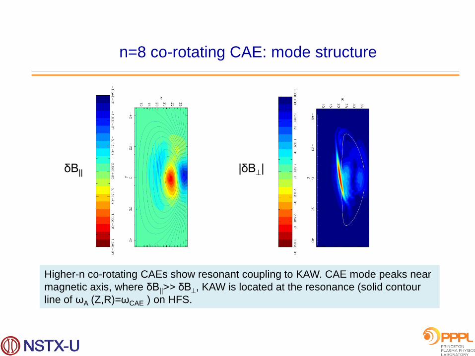
n=8 co-rotating CAE: mode structure
|δB| δB||
Higher-n co-rotating CAEs show resonant coupling to KAW. CAE mode peaks near
magnetic axis, where δB||>> δB, KAW is located at the resonance (solid contour
line of ωA (Z,R)=ωCAE ) on HFS.

Low-n and high-n CAE modes show coupling to KAW
δE||
Poloidal and equatorial plane
contour plots of δE|| , solid line
is contour of ωA (Z,R)= ωCAE ,
where ωA (Z,R)= VA n/R.
Radial profiles of Alfven continuum and
δE|| for n=8. Radial width of KAW is
comparable to beam ions Larmor radius.
KAW can have strong effect on electron
transport due to finite δE||.
Raxis
ωCAE
ωA
R/λ
nbeam
δE||

KAW dispersion relation
k
e wher
,4
3
4
31
2
2
2
222
||
2
cii
ci
b
e
b
i
e
i
eA
m
T
n
n
n
nVk
k
,4
31
2
2
2
222
||
2
cii
b
b
cie
b
b
e
b
Am
T
n
n
n
nVk
KAW in HYM model:
- consistent with full kinetic in the limit λe→0, λi→0, and ω<<ωci.
Scale-length for beam-KAW is the beam ion Larmor radius.
KAW in full kinetic model:
- assuming three-component plasma, Maxwellian ions with V0=0, and including only
adiabatic beam ions response (non-perturbative).

Relation between CAE/KAW and Te flattening?
Fraction of NBI power transferred to CAE can
be estimated as:
P= 2γ ∫ (δB)2/4π d3x,
where δB/B0= (0.9-3.4)×10-3 corresponds to
measured displacement |ξ|= 0.1-0.4 mm [N.Crocker’13] (based on HYM-calculated linear
mode structure for the n=4 CAE).
For γ/ωci=0.005-0.01, P= (0.013-0.4)MW,
- significant fraction of NBI energy can be
transferred to several unstable CAEs of
relatively large amplitudes.
Energy flux from the CAE to the KAW and
dissipation at the resonance location can
have a strong effect on the temperature
profile.
Radial component of quasilinear
Poynting vector S=<ExB>.
Energy flux is directed away from
magnetic axis, ie from CAE to
KAW.
SR
Raxis

Summary (NSTX)
• Unstable CAE modes couple with KAW on the HFS. Resonance with
KAW is located at the edge of CAE well, and just inside beam ion density
profile. Radial width of KAW is comparable to beam ion Larmor radius.
• A significant fraction of NBI energy can be transferred to several unstable
CAEs: P~0.4MW for δB/B0 ~10-3 .
• Energy flux from the CAE to KAW and dissipation at the resonant location
can have direct effect on electron temperature profile.
• In addition, radially overlapping KAWs can strongly enhance plasma heat
transport due to finite δE|| and large width of resonant mode.
• Detailed comparison of the relative importance of the energy channelling
and anomalous electron transport mechanisms will require fully nonlinear
simulations, and will be performed in the future.

2D hybrid simulations of spheromak merging
• Hybrid simulations of counter-helicity spheromak merging have been compared with
MHD simulations.
• For large resistivity (Lundquist number S~500), there were significant differences
between hybrid and MHD simulations: in the MHD runs, spheromaks merged
completely in about 10tA, whereas in hybrid simulations there was no complete
reconnection.
• For lower resistivity with S~1500, hybrid simulation results were generally similar to
the MHD simulations, and spheromaks were completely merged forming an FRC by t~
6tA.
• Hybrid simulations show shorter current layer and significantly wider velocity profiles.
Contour plots of (a) toroidal
current and (b) toroidal
velocity from 2D hybrid
simulations and 2D MHD
simulations of counter-
helicity spheromak merging.
(a) (b)
Hybrid
MHD
Hybrid
MHD

(a) Simulation results showing
magnetic field lines and self-
generated toroidal field contours of
the relaxed configuration;
(b) Experimental results showing
dependence of the flux rope
expansion on the current strength,
and a self-generated toroidal field
(C. Myers).
(b) (a)
3D MHD simulations in support of MRX flux-rope experiments
The goal of the numerical studies is to determine the threshold current
below which force balance can be found (without flux-rope eruption) for a
given external field configuration, and to guide the design of optimal coil
configurations for future experiments on MRX.
Large toroidal current has been added to external toroidal field at
t=0, and configuration was allowed to relax to an equilibrium state.

3D stability simulations (larger Vbeam )
Jφ, beam
P
Beam parameters: V0 =5.6 VA, vth = 1.5 VA , nb = 1% n0 .
For these beam parameters, the n=1 tilt mode and n=3 modes are completely stabilized, but the n=2 rotational mode is still unstable with γ = γmhd(n=2) – beam has little effect on n=2 mode.
t / tA
- n=0 - n=1 - n=2 - n=3 - n=4
|Vn |2
After relaxation, FRC elongates. The beam ions have wider axial profiles for larger vth.
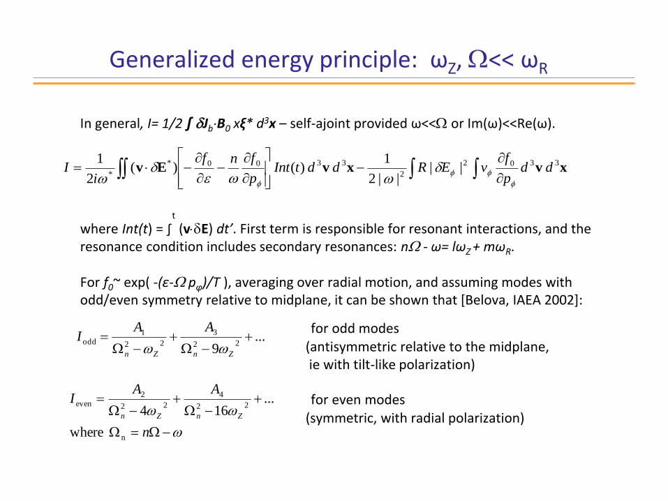
Generalized energy principle: ωZ, << ωR
In general, I= 1/2 ∫ JbB0 xξ* d3x – self-ajoint provided ω<< or Im(ω)<<Re(ω).
where Int(t) = ∫
t
(vE) dt’. First term is responsible for resonant interactions, and the resonance condition includes secondary resonances: n - ω= lωZ + mωR. For f0~ exp( -(ε- pφ)/T ), averaging over radial motion, and assuming modes with odd/even symmetry relative to midplane, it can be shown that [Belova, IAEA 2002]:
for odd modes (antisymmetric relative to the midplane, ie with tilt-like polarization)
for even modes (symmetric, with radial polarization)
...9
22
3
22
1odd
ZnZn
AAI
n
AAI
ZnZn
n
22
4
22
2even
where
...164
xvxvEv3302
2
3300*
* ||
||2
1 )( )(
2
1dd
p
fvERddtInt
p
fnf
iI

Generalized energy principle: ωZ<< ~ ωR
Radial resonances are more important for low S* configurations (because Vb>>vth,I implies ~ ωR ~ ωci), and for modes with even polarization (radial modes). where resonant condition: n - ω= ωR.
22
32
2
22
2
2
22
0 1 ~
||
||2 RnRn
n
b dRR
En
T
RI
x

Dependence of betatron frequencies on S* and tor
S*=20, 0=0.8, nb/n0=0.013, Jb/J0=0.7
ωZ
ωR
t
2=ωR
=ωZ
ωZ : : ωR = 0.7:1:2
nbeam
Ratio of radial orbit frequency ωR to toroidal frequency is ωR / ~ 2, and the n=2 mode is the most unstable mode.
t / tA
- n=0 - n=1 - n=2 - n=3 - n=4
|Vn |2

Dependence of betatron frequencies on S* and tor
S*=20, 0=0.2, nb/n0=0.05, Jb/J0=0.7
ωZ
ωR
t
4=ωR
=ωZ
ωZ : : ωR = 1:1:4
t / tA
- n=0 - n=1 - n=2 - n=3 - n=4
|Vn |2
nbeam
Ratio of radial orbit frequency ωR to toroidal frequency is ωR / ~ 4, so that resonant condition is satisfied: n ωR for the n=4 mode.
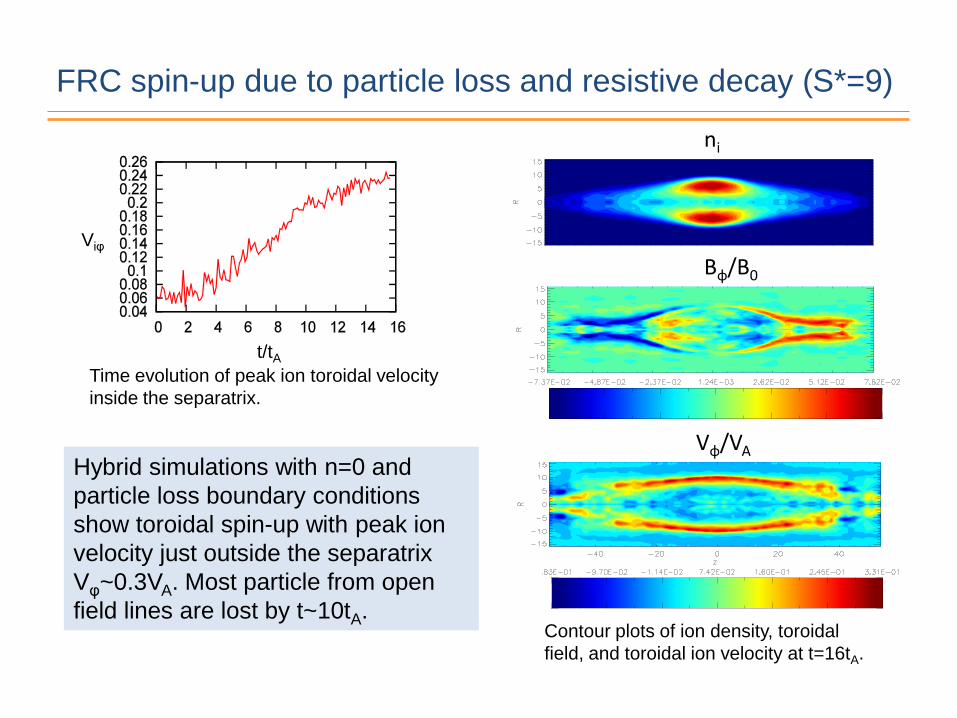
FRC spin-up due to particle loss and resistive decay (S*=9)
Hybrid simulations with n=0 and
particle loss boundary conditions
show toroidal spin-up with peak ion
velocity just outside the separatrix
Vφ~0.3VA. Most particle from open
field lines are lost by t~10tA. Contour plots of ion density, toroidal
field, and toroidal ion velocity at t=16tA.
t/tA
Viφ
Bφ/B0
Vφ/VA
ni
Time evolution of peak ion toroidal velocity
inside the separatrix.

FRC spin-up: velocity evolution S*=9
t= 10tA
t= 20tA
t= 30tA
Time evolution of ion toroidal velocity:
contour plots and radial profiles of Vφ.
Vφ/VA
R
Vφ/VA
R
Vφ/VA
R
0.2
0.0
-0.2
0.3
0.0
0.4
0.2
0.0

Simulations including the particle loss and periodic BCs:
n=1 tilt and n=2 rotational mode(S*=9)
• Low plasma resistivity, S~ 4400:
- the n=1 tilt mode is unstable and
saturates at t~35tA, the n=2
rotational mode becomes unstable
– no saturation.
• High resistivity, S~ 1500:
all low-n modes are stable for.
t / tA
- n=0 - n=1 - n=2 - n=3 - n=4
|Vn |2
t / tA
- n=0 - n=1 - n=2 - n=3 - n=4
|Vn |2
S=1500
S=4400

Simulations including the particle loss and end-shorting:
unstable n=1 tilt → n=2 rotational mode (S*=9)
t / tA
- n=0 - n=1 - n=2 - n=3 - n=4
|Vn |2
t / tA
- n=0 - n=1 - n=2 - n=3 - n=4
|Vn |2 Vφ
t / tA
Time evolution of peak ion toroidal velocity inside
the separatrix from end-shortening simulations
(red) and without end-shorting (green).
Time evolution n=0-4 mode amplitudes
from simulations with particle loss: (a) with
end-shortening; (b) without end-shorting.
High resistivity, S~ 1500.
End-shorting
Periodic
End-shorting
Periodic
• End-shorting results in faster spin-up
and instability of n=1 tilt and
subsequent growth of the n=2
rotational mode.
• All n=1-4 modes are stable without
end shorting for large enough
resistivity (periodic BC, no ion rotation
at t=0).
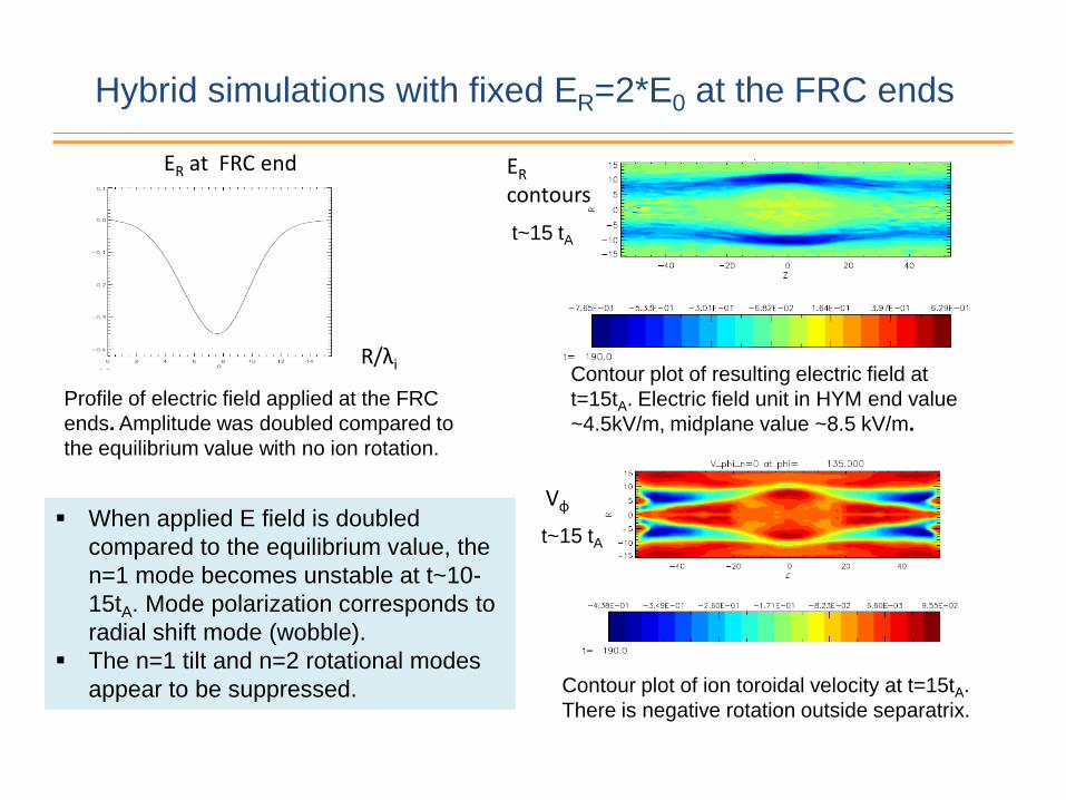
R/λi
ER at FRC end
Contour plot of resulting electric field at
t=15tA. Electric field unit in HYM end value
~4.5kV/m, midplane value ~8.5 kV/m.
ER
contours
Vφ
t~15 tA
t~15 tA
Hybrid simulations with fixed ER=2*E0 at the FRC ends
Profile of electric field applied at the FRC
ends. Amplitude was doubled compared to
the equilibrium value with no ion rotation.
Contour plot of ion toroidal velocity at t=15tA.
There is negative rotation outside separatrix.
When applied E field is doubled
compared to the equilibrium value, the
n=1 mode becomes unstable at t~10-
15tA. Mode polarization corresponds to
radial shift mode (wobble).
The n=1 tilt and n=2 rotational modes
appear to be suppressed.

Hybrid simulations with fixed ER=2*E0 at the FRC ends
- n=0 - n=1 - n=2 - n=3 - n=4
t / tA
|Ji |2
t=30tA Perturbed density
t=30tA
Perturbed velocity at midplane
Polarization of unstable n=1 mode corresponds to radial shift mode, as can be seen from δn and δV plots. Perturbed axial velocity is small compared to δVφ and δVR. Mode rotates in the e-diamagnetic direction with ω~0.06ωci.
δVZ
Time evolution n=0-4 mode energies from
simulations with end-applied bias field for S*=9.
Vmax=0.1VA

Non-symmetric BCs: left side – end-shorting,
right side – fixed value E=E0.
- n=0 - n=1 - n=2 - n=3 - n=4
t / tA
|Ji |2
Time evolution n=0-4 mode energies
from simulations with non-symmetric
boundary conditions. The n=1 mode has
radial polarization, ie wobble-like mode.
Plasma density at t=20tA and t=30tA.
Toroidal velocity at t=25tA.
δn
25tA
n
30tA
Conclusions (FRC)
• Beam-driven instabilities can be predicted based on energy principle.
• Simulations including the particle loss and periodic BCs show all low-n modes stable for large resistivity.
• End-shorting results in faster spin-up and instability of n=1 tilt and subsequent growth of the n=2 rotational mode.
• When applied ER field is doubled compared to the equilibrium value, the n=1 mode becomes unstable at t~10-15tA. Mode polarization corresponds to radial shift mode (wobble). • Hybrid simulations with non-symmetric BCs with/without end-shorting show strongly unstable n=1 radial shift (wobble) mode.


![LEPTANILLA (HYM.: WHEELER, - Hindawi Publishing ...downloads.hindawi.com/journals/psyche/1928/034510.pdf1928] TheLarva of Leptanilla 85 THELARVA OF LEPTANILLA(HYM.: FORMICID_E) ByGEORGEC.](https://static.fdocuments.in/doc/165x107/5aa749e37f8b9a50528c2b40/leptanilla-hym-wheeler-hindawi-publishing-thelarva-of-leptanilla-85-thelarva.jpg)