Using Small Antenna for Portable Operations PDF | QRZ Forums
11
Using small antenna for portable operations Ulrich L. Rohde, N1 UL Introduction: There is a big interest in “Summit on the Air (SOTA) activities using light and portable radio equipment. While my favorite ICOM 703 (as it combined HF and a nice antenna tuner) has disappeared Icon recently announced a new multipurpose HF/VHF/UHF radio model IC 705, maybe for summer shipment in 2020. The current leaders are the ELECRAFT KX3 and the Yeasu 818. However the best transceiver is useless unless connected to a good antenna. When introducing the 703 it came with a nice small antenna operating from 40 m to 6 m. The reviews of this antenna were mixed; 40 m was considered suboptimal and with 20 m and higher most were happy. The AH 703 antenna came with a set of 5 m insulated wires covered with plastic. As we all are interested to get good reports, most S-meters are estimators and besides the software defined radios (SDR) none of the QRP radio make any effort to correct this. The new ICOM IC R8600 allows a correct setting of dBuV, which is really helpful. The deviation from linearity is less then 0.1dB! The 5 m wire when packed up have a tendency to tangle themselves resulting in a mess. Banana silicone leads are a better solution. The VOLTCRAFT measuring cable MSB-300 consists of a particularly flexible cable with welded 4 mm Lamella plugs. The cable material is reinforced with particularly tear-resistant plastic fibers to increase the tensile strength. The measuring lead is insulated with silicone and insensitive to heat damage that can occur when working with hot soldering iron. The measuring cable is double-insulated in two colors. If the first insulating layer is damaged, a different colored insulation is revealed. In addition, the hard nickel- plated surface finish of the 4 mm Lamella plug allows a high number of mating cycle. I use 4 pieces with 5 m length. At 2 x 5 m I get 2 resonant of 10 m cables, quarter wave length at 40m, using only 2 x 5 m resonant they are resonant at 20 m. And for 10 m operation I use 2 cables 5 m long in parallel, resulting in 2.5 m.
Transcript of Using Small Antenna for Portable Operations PDF | QRZ Forums

Using small antenna for portable operations
Ulrich L. Rohde, N1 UL
Introduction:
There is a big interest in “Summit on the Air (SOTA) activities using light and
portable radio equipment. While my favorite ICOM 703 (as it combined HF and a
nice antenna tuner) has disappeared Icon recently announced a new
multipurpose HF/VHF/UHF radio model IC 705, maybe for summer shipment in
2020. The current leaders are the ELECRAFT KX3 and the Yeasu 818. However the
best transceiver is useless unless connected to a good antenna. When introducing
the 703 it came with a nice small antenna operating from 40 m to 6 m. The
reviews of this antenna were mixed; 40 m was considered suboptimal and with 20
m and higher most were happy. The AH 703 antenna came with a set of 5 m
insulated wires covered with plastic. As we all are interested to get good reports,
most S-meters are estimators and besides the software defined radios (SDR) none
of the QRP radio make any effort to correct this. The new ICOM IC R8600 allows a
correct setting of dBuV, which is really helpful. The deviation from linearity is less
then 0.1dB!
The 5 m wire when packed up have a tendency to tangle themselves resulting in a
mess. Banana silicone leads are a better solution. The VOLTCRAFT measuring
cable MSB-300 consists of a particularly flexible cable with welded 4 mm Lamella
plugs. The cable material is reinforced with particularly tear-resistant plastic fibers
to increase the tensile strength. The measuring lead is insulated with silicone and
insensitive to heat damage that can occur when working with hot soldering iron.
The measuring cable is double-insulated in two colors. If the first insulating layer
is damaged, a different colored insulation is revealed. In addition, the hard nickel-
plated surface finish of the 4 mm Lamella plug allows a high number of mating
cycle. I use 4 pieces with 5 m length. At 2 x 5 m I get 2 resonant of 10 m cables,
quarter wave length at 40m, using only 2 x 5 m resonant they are resonant at 20
m. And for 10 m operation I use 2 cables 5 m long in parallel, resulting in 2.5 m.

As the cable use plastic fiber they resonate “electrically” lower in frequency than
an uncoated wire, here an antenna tuner is helpful.
The multiband antenna:
Besides the discontinued AH 703 there are other choices. As an example there is
the OUTBACKER antenna, made by Terry Clinch in Perth Western Australia.
For ease of operation tap points, frequencies or bands are clearly and permanently engraved into the antenna, the wander lead is used for quick, easy, manual channel changing just plug one end into the lowest socket, wind lead around the antenna and plug the other end into the required frequency.

The AH 703, nice and small for backpack operation operates similarly and will be used here to show some of the effects of grounding and tuning .It can be preset for 40, 20, 15, 10 and 6 m operation. Typical bandwidth for VSWR= 1.5 is
on 40m 25 KHz - 20m 200 KHz - 15m 250 KHz - 10m 600 KHz
The measurements:

As mentioned, most liked the AH 703 very much on the 20 m band, so I tuned the
Antenna to 14.200 MHz; this was uneventful and worked well. While any Antenna
Analyzer will work well I used the calibrated Rohde & Schwarz FSH4 spectrum
Analyzer /Network analyzer that operates from 100 KHz to 3.6 GHz.
The unit was calibrated up to 1 GHz, the un-calibrated statement is misleading.
Now to 40 m:
The AH 703 was then attached to the input/output N connector; the output
connector for the tracking generator was used to attach the radial wire.

Without a ground radial, just resonating against the instrument case, the
resonance frequency is above 7.6 MHz, definitely out of band, as can be seen
above.
The next logical step was to connect one of the 5 m radials. The result is dramatic
as can be seen. The resonant frequency jumped to about 6.9 MHz, now below the
ham band. This shows how important radials are.
Icom delivered 2 radials, about 5 m each, so the next logical step was to use those
radials and evaluate the results.
The additional radial moved the resonant frequency to about 6.8 MHz that is
beyond the tuning range of the adjustable antenna element.
It was further noticed that the antenna top was extremely sensitive to the
proximity of object. By approaching the antenna tip within 20 inch the antenna
started to be mistuned. As the top rod is very flexible, if using this with a

backpack, the VSWR will vary extremely. If the material is not stiff, the system’s
VSWR will be all over.
While the VSWR indication may be less interesting, as it remains a scalar
value, a Smith diagram will give more insight!

At about resonance the Smith chart claims about 37, 8 Ohm real and –j2.45
Ohm imaginary. This is the impedance chart, not the admittance chart; the two
values, real and imaginary are in series.
If we remember from other publications the mentioning of ground losses,
coil losses and the fact that the radiation resistance is
Rr= 60 x Pi^2x(l/lambda)^2 =592.176 x (1/4)^2=592.176 x (1/16)= 37 Ohm !
The tuning rod is about 45 cm long. As 1m wire is typically 25 pF, we can
assume 12 pF as reasonable. To be resonant a 43 uh loading coil is needed.
The inductance impedance is 1.9 KOhm and based on the Rr of 37 Ohm the
loaded Q would be 54.

Then the 3 dB bandwidth about 130 Khz.
Now to the final test, using 2 radials of 10 m each mode of the yellow
cables with the universal banana plugs.
What a surprise. Two 10 m radials act like a dipole on the grund, each side
quarter wave length and detune the system even further, the VSWR gets better.
Assuming that the transmitter can handler a VSWR of 2 (military manpacks are
more rugged, they can handle VSWR of 3), the operating bandwidth now is 100
KHz.

There is another problem which I experienced. The somewhat simple
antenna tuner of the ICOM 703 cannot handle such a steep impedance change.
Using the Hustle rod and loading coil and ground radial wires, the detuning
was less.
The Hustler antennas have a non-metric thread so an adapter was needed
to UHF and then further to TNC. The yellow cable, described above, allows all
kind of radial combination. This picture was taken during the 20 m test.

Summary:
The use of rod antennas at HF frequencies and portable equipment is not as
trivial as many publication claim. Most of the Yeasu 817/18 users also own an
antenna tuner, the Elecraft model has one build in. The fact that the ICOM 705
has no tuner complicates portable operation. A symmetrical dipole eliminates the
ground problems but an unbalanced to balance transformer is needed, better
with an antenna tuner handy. It would be really nice to have a 20 W ATU with
both balanced and unbalanced output that automatically gets activated by an RF
pulse and can be at the dipole feeding point. In this manner the dipole or even an
inverted V can be aperiodic; a useful length would be 5 to 7 m for each leg.
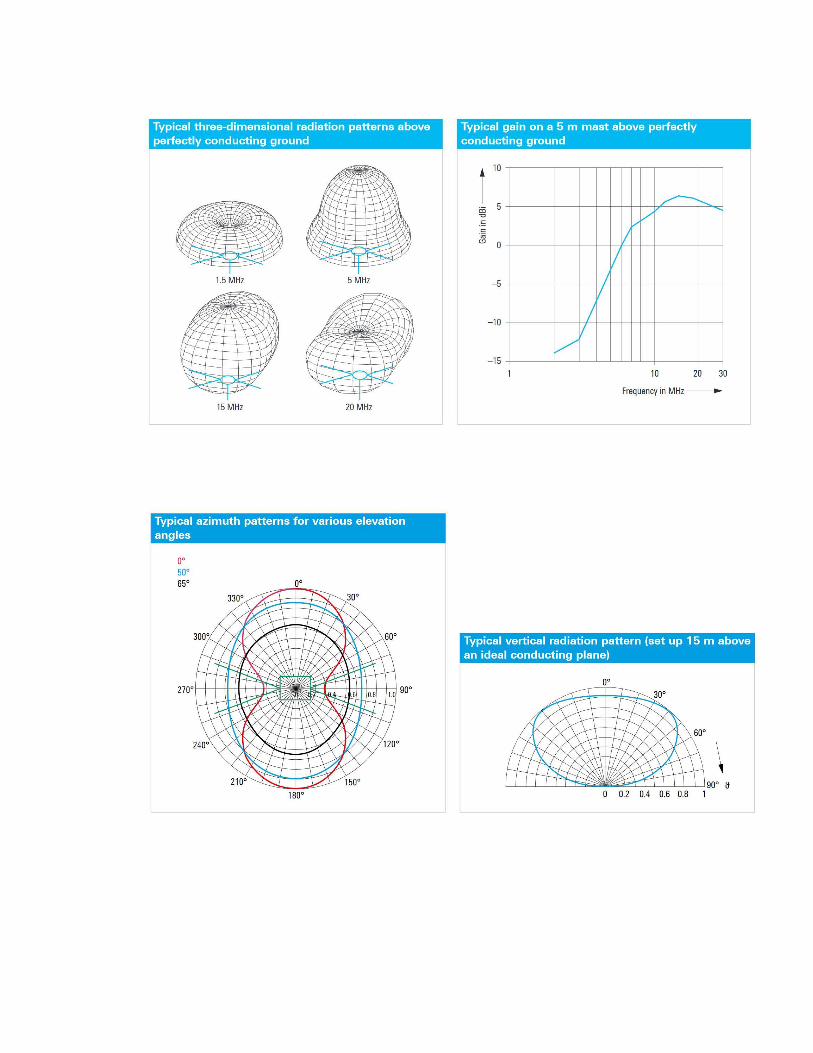
The plots below show aperiodic dipole with two 5 m arms and an antenna
tuner. Even on 4 MHz (80m band) the 6dB losses are acceptable and at 40 m long
distance contacts are doing well. For field day operation having all bands available
this arrangement gives a huge advantage. R&S HX002H2.