Using slimline borehole radars from cover holes - …€¦ · Using slimline borehole radars from...
6
10th SAGA Biennial Technical Meeting and Exhibition Wild Coast 24 - 26 October 2007, Preview Using slimline borehole radars from cover holes Andrew Bray 1 , Tim Sindle 1 , Iain Mason 1 , Keith Palmer 4 , Johannes Cloete 4 , Jan Steenkamp 2 , Petro du Pisani 3 & Kazek Trofimczyk 3 1. School of Geosciences, University of Sydney, Australia. [email protected] 2. Digital Surveying, Carletonville, South Africa. [email protected] 3. Anglo Operations Ltd, Johannesburg South Africa. [email protected] 4. Dept of Electronic Engineering, Stellenbosch, South Africa. [email protected] ABSTRACT Cover boreholes are drilled prior to mining in order to give fair warning of water-bearing fissures and potentially hazardous structures. Hitherto, cover boreholes have had to hit these structures to detect them. Many South African Bushveld platinum ore bodies are hosted by VHF radar-translucent hard rocks. The rock volumes, which are investigated by pilot and cover boreholes, can be expanded economically, without a geophysicist on site, by running rugged borehole radars down these boreholes. Borehole radar (BHR) ruggedisation and automation has opened roads both to the reconstruction of accurate BHR images from radars that are deployed by cover hole drillers “on-the-rod”, and to the mapping of steeply dipping structures (faults, dykes) from shaft pilot boreholes to depths greater than three kilometres. “On-the-rod” (OTR) deployment allows radars to go wherever drill strings can reach. It facilitates the running of borehole radars at low cost in collapsing ground, without grouting. The irregular motion of a borehole radar probe on a low cost drill string does blur the BHR profile, but we demonstrate here that blurring is reversible, if BHR sampling intervals are sub-wavelength. Near-vertical faults present edge-on to surface and are hard to detect conventionally. Vertical borehole BHR surveys are well placed for steep-dip structural mapping. Key words: Borehole radar, wireline logging, hazard detection, cover holes INTRODUCTION The volume investigated by a borehole is small. Hitherto, to detect a hazardous structure, a cover hole has had to hit it. A miss by inches is as good as a miss by miles. But, many hard rocks are translucent to borehole radar (Trickett et al 1998, Vogt 2004, Vogt & Du Pisani 2004 Simmat et al 2006). Here surveys of a Bushveld vertical shaft pilot borehole; and a 135m near- horizontal underground cover borehole, show how BHR can expand a coverhole’s radius of investigation. MONOSTATIC BOREHOLE RADARS The radar used in the trials reported here was a monostatic borehole radar, i.e. transmitter and receiver shared the 1.6m long case. A VHF duplexer protected the receiver. The radar had a core diameter of 28.575mm. The transmitter fired a train of -400V steps at ~11kHz PRF into a broadband (10-125MHz) asymmetric dipole. One dipole arm was resistively loaded; the other, a metal tube, housed the electronics. Echoes, amplified, were fed to a 250MS/s analog-to- digital converter (ADC) controlled by a field programmable gate array (FPGA). Stacking in the FPGA raised dynamic range to 12 bits (70dB). Traces accumulate in an on-board flash memory, which was downloaded via Bluetooth when the transceiver returned to surface. High speed downhole memory logging allowed the radar to run deep downhole on light-weight cords, self-supporting, self-adjusting and umbilical free. COVERHOLE DRILLING & MAPPING Surface shaft pilot boreholes and underground cover boreholes are both used to find hazardous structures ahead of planned mine development. Before sinking a shaft, a borehole is usually drilled down the proposed shaft axis. During tunnelling, cover boreholes angled at 5 o from the advance are drilled from cubbies spaced at 110m. Lengths of 140m give ~30m overlap. By-Laws in many South African gold mines require that “No development may advance closer than 12m to a known water-bearing fissure or 12m from the cover offered by a cover hole”(D Kershaw pers comm.). Compliance requires that the cover boreholes be surveyed directionally, for boreholes often deflect appreciably clockwise i.e. in the direction of spin. 1
Transcript of Using slimline borehole radars from cover holes - …€¦ · Using slimline borehole radars from...
10th SAGA Biennial Technical Meeting and Exhibition Wild Coast 24 - 26 October 2007, Preview
Using slimline borehole radars from cover holes
Andrew Bray1, Tim Sindle1, Iain Mason1, Keith Palmer4, Johannes Cloete4, Jan Steenkamp2, Petro du Pisani3 & Kazek Trofimczyk3
1. School of Geosciences, University of Sydney, Australia. [email protected] 2. Digital Surveying, Carletonville, South Africa. [email protected]
3. Anglo Operations Ltd, Johannesburg South Africa. [email protected] 4. Dept of Electronic Engineering, Stellenbosch, South Africa. [email protected]
ABSTRACT Cover boreholes are drilled prior to mining in order to give fair warning of water-bearing fissures and potentially hazardous structures. Hitherto, cover boreholes have had to hit these structures to detect them. Many South African Bushveld platinum ore bodies are hosted by VHF radar-translucent hard rocks. The rock volumes, which are investigated by pilot and cover boreholes, can be expanded economically, without a geophysicist on site, by running rugged borehole radars down these boreholes. Borehole radar (BHR) ruggedisation and automation has opened roads both to the reconstruction of accurate BHR images from radars that are deployed by cover hole drillers “on-the-rod”, and to the mapping of steeply dipping structures (faults, dykes) from shaft pilot boreholes to depths greater than three kilometres. “On-the-rod” (OTR) deployment allows radars to go wherever drill strings can reach. It facilitates the running of borehole radars at low cost in collapsing ground, without grouting. The irregular motion of a borehole radar probe on a low cost drill string does blur the BHR profile, but we demonstrate here that blurring is reversible, if BHR sampling intervals are sub-wavelength. Near-vertical faults present edge-on to surface and are hard to detect conventionally. Vertical borehole BHR surveys are well placed for steep-dip structural mapping. Key words: Borehole radar, wireline logging, hazard detection, cover holes
INTRODUCTION The volume investigated by a borehole is small. Hitherto, to detect a hazardous structure, a cover hole has had to hit it. A miss by inches is as good as a miss by miles. But, many hard rocks are translucent to borehole radar (Trickett et al 1998, Vogt 2004, Vogt & Du Pisani 2004 Simmat et al 2006). Here surveys of a Bushveld vertical shaft pilot borehole; and a 135m near-horizontal underground cover borehole, show how BHR can expand a coverhole’s radius of investigation. MONOSTATIC BOREHOLE RADARS The radar used in the trials reported here was a monostatic borehole radar, i.e. transmitter and receiver shared the 1.6m long case. A VHF duplexer protected the receiver. The radar had a core diameter of 28.575mm. The transmitter fired a train of -400V steps at ~11kHz PRF into a broadband (10-125MHz) asymmetric dipole. One dipole arm was resistively loaded; the other, a metal tube, housed the electronics. Echoes, amplified, were fed to a 250MS/s analog-to-digital converter (ADC) controlled by a field programmable gate array (FPGA). Stacking in the
FPGA raised dynamic range to 12 bits (70dB). Traces accumulate in an on-board flash memory, which was downloaded via Bluetooth when the transceiver returned to surface. High speed downhole memory logging allowed the radar to run deep downhole on light-weight cords, self-supporting, self-adjusting and umbilical free. COVERHOLE DRILLING & MAPPING Surface shaft pilot boreholes and underground cover boreholes are both used to find hazardous structures ahead of planned mine development. Before sinking a shaft, a borehole is usually drilled down the proposed shaft axis. During tunnelling, cover boreholes angled at 5o from the advance are drilled from cubbies spaced at 110m. Lengths of 140m give ~30m overlap. By-Laws in many South African gold mines require that “No development may advance closer than 12m to a known water-bearing fissure or 12m from the cover offered by a cover hole”(D Kershaw pers comm.). Compliance requires that the cover boreholes be surveyed directionally, for boreholes often deflect appreciably clockwise i.e. in the direction of spin.
1
Covering coverholes with BHR
The art of cover borehole trajectory surveying is well established. “On-the-rod” trajectory survey techniques are familiar. This experience can be drawn upon by BHR surveyors, because monostatic borehole radars physically resemble electronic multi-shot survey tools. RADAR SURVEYS “ON-THE-RODS” Most South African underground cover boreholes are drilled using pneumatic MetreEaters or Kempes to bore 47.75mm diameter boreholes up to 200m long. Present interest in the drill in Figure 1 lies in the “pneumatic rod puller”, which punches or jerks the drill string into or out of the borehole in steps that are set by the (adjustable) 76cm stroke length. The step rate is set by the driller, the step length by the piston stroke. A monostatic radar that follows this motion can be fed down the centre of a drill string or screwed onto its far end. Steps should be short enough to Nyquist sample the borehole i.e stations at each step should be <0.5λ min apart. The radar should stay on station for long enough i.e. >2s to acquire at least one trace at each station.
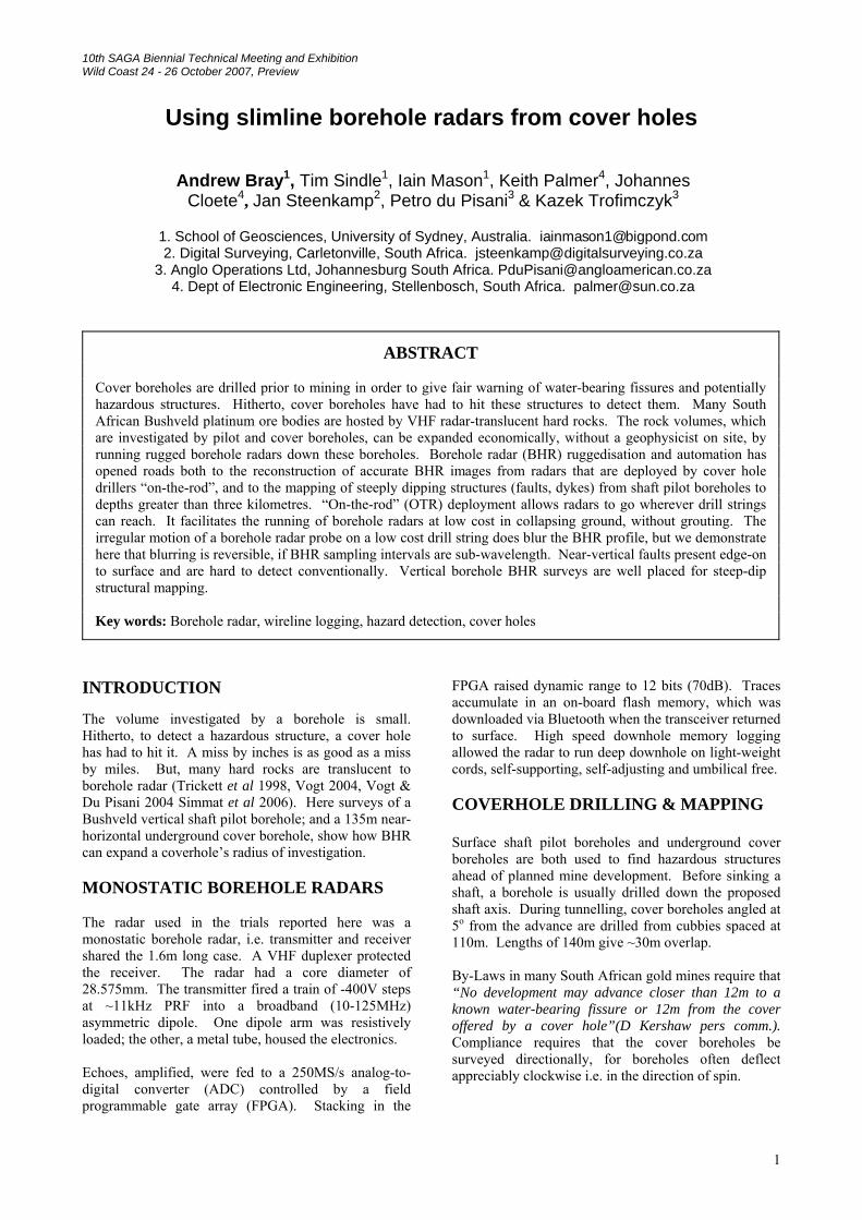
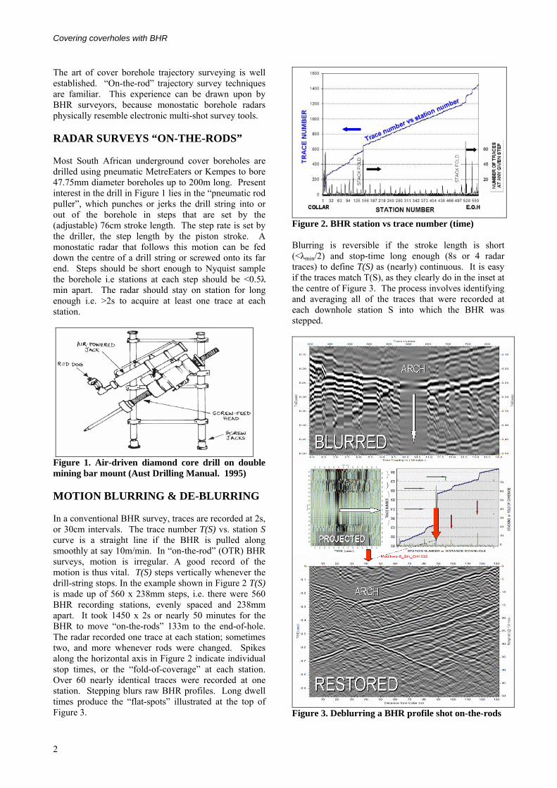
Figure 1. Air-driven diamond core drill on double mining bar mount (Aust Drilling Manual. 1995) MOTION BLURRING & DE-BLURRING In a conventional BHR survey, traces are recorded at 2s, or 30cm intervals. The trace number T(S) vs. station S curve is a straight line if the BHR is pulled along smoothly at say 10m/min. In “on-the-rod” (OTR) BHR surveys, motion is irregular. A good record of the motion is thus vital. T(S) steps vertically whenever the drill-string stops. In the example shown in Figure 2 T(S) is made up of 560 x 238mm steps, i.e. there were 560 BHR recording stations, evenly spaced and 238mm apart. It took 1450 x 2s or nearly 50 minutes for the BHR to move “on-the-rods” 133m to the end-of-hole. The radar recorded one trace at each station; sometimes two, and more whenever rods were changed. Spikes along the horizontal axis in Figure 2 indicate individual stop times, or the “fold-of-coverage” at each station. Over 60 nearly identical traces were recorded at one station. Stepping blurs raw BHR profiles. Long dwell times produce the “flat-spots” illustrated at the top of Figure 3.
Figure 2. BHR station vs trace number (time) Blurring is reversible if the stroke length is short (<λmin/2) and stop-time long enough (8s or 4 radar traces) to define T(S) as (nearly) continuous. It is easy if the traces match T(S), as they clearly do in the inset at the centre of Figure 3. The process involves identifying and averaging all of the traces that were recorded at each downhole station S into which the BHR was stepped.
Figure 3. Deblurring a BHR profile shot on-the-rods
2
Bray, Sindle et al
RAISING COVERHOLE COVERAGE As noted in the introduction, hitherto to detect a hazardous structure, a cover borehole has had to hit it. The aim in drilling a cover borehole is to spot potentially hazardous objects. The diffraction arch that appears after deblurring the OTR time section in Figure 3 is a clear sign of one such object. In this case the object is a known tunnel 20m from the borehole. Huygens-Kirchhoff (HK) diffraction stack migration1 into the borehole’s sagittal plane2 collapses the diffraction arches in Figure 3 into the image that is ringed in Figure 4. HK migration also translates the echoes from reflecting planes to their true positions relative to the borehole. The borehole rises into the 5m Footwall Marker of the UG2, echoes from which form the dominant reflector. The fact that diffractions from a known object collapse successfully into the ring in Figure 4 confirms the practical feasibility of deblurring OTR BHR sections.
Figure 4. Migrated profile, linking an off-axis tunnel 20m from the borehole to the diffraction arch in Figure 3
1 pre-stack migration, 25m rolling sub-aperture, cos**2 obliquity factor, borehole radar velocity 105m/us 2 The sagittal plane contains both the borehole and its virtual image(s) reflected in the bedding plane(s)
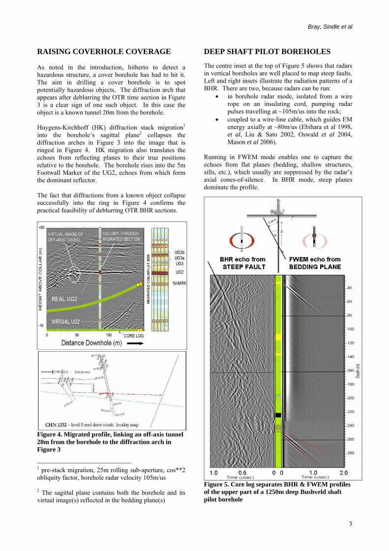
DEEP SHAFT PILOT BOREHOLES The centre inset at the top of Figure 5 shows that radars in vertical boreholes are well placed to map steep faults. Left and right insets illustrate the radiation patterns of a BHR. There are two, because radars can be run:
• in borehole radar mode, isolated from a wire rope on an insulating cord, pumping radar pulses travelling at ~105m/us into the rock;
• coupled to a wire-line cable, which guides EM energy axially at ~80m/us (Ebihara et al 1998, et al, Liu & Sato 2002, Oswald et al 2004, Mason et al 2006).
Running in FWEM mode enables one to capture the echoes from flat planes (bedding, shallow structures, sills, etc.), which usually are suppressed by the radar’s axial cones-of-silence. In BHR mode, steep planes dominate the profile.
Figure 5. Core log separates BHR & FWEM profiles of the upper part of a 1250m deep Bushveld shaft pilot borehole
3
Covering coverholes with BHR
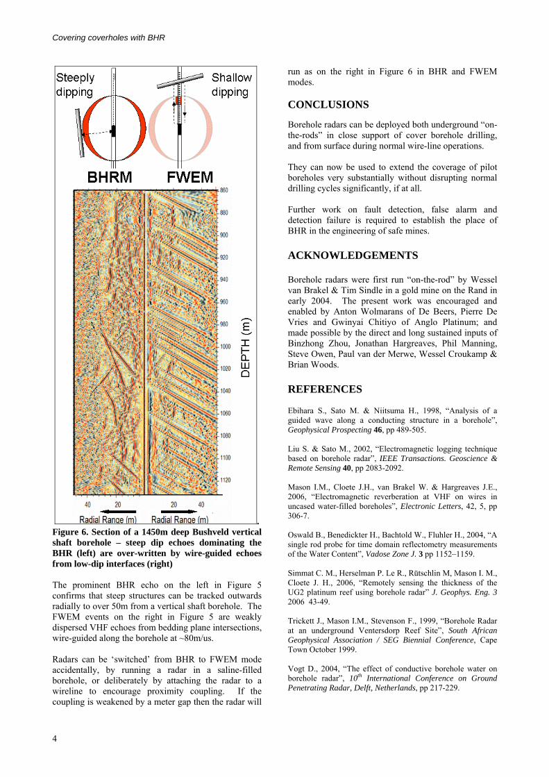
. Figure 6. Section of a 1450m deep Bushveld vertical shaft borehole – steep dip echoes dominating the BHR (left) are over-written by wire-guided echoes from low-dip interfaces (right) The prominent BHR echo on the left in Figure 5 confirms that steep structures can be tracked outwards radially to over 50m from a vertical shaft borehole. The FWEM events on the right in Figure 5 are weakly dispersed VHF echoes from bedding plane intersections, wire-guided along the borehole at ~80m/us. Radars can be ‘switched’ from BHR to FWEM mode accidentally, by running a radar in a saline-filled borehole, or deliberately by attaching the radar to a wireline to encourage proximity coupling. If the coupling is weakened by a meter gap then the radar will
run as on the right in Figure 6 in BHR and FWEM modes. CONCLUSIONS Borehole radars can be deployed both underground “on-the-rods” in close support of cover borehole drilling, and from surface during normal wire-line operations. They can now be used to extend the coverage of pilot boreholes very substantially without disrupting normal drilling cycles significantly, if at all. Further work on fault detection, false alarm and detection failure is required to establish the place of BHR in the engineering of safe mines. ACKNOWLEDGEMENTS Borehole radars were first run “on-the-rod” by Wessel van Brakel & Tim Sindle in a gold mine on the Rand in early 2004. The present work was encouraged and enabled by Anton Wolmarans of De Beers, Pierre De Vries and Gwinyai Chitiyo of Anglo Platinum; and made possible by the direct and long sustained inputs of Binzhong Zhou, Jonathan Hargreaves, Phil Manning, Steve Owen, Paul van der Merwe, Wessel Croukamp & Brian Woods. REFERENCES Ebihara S., Sato M. & Niitsuma H., 1998, “Analysis of a guided wave along a conducting structure in a borehole”, Geophysical Prospecting 46, pp 489-505. Liu S. & Sato M., 2002, “Electromagnetic logging technique based on borehole radar”, IEEE Transactions. Geoscience & Remote Sensing 40, pp 2083-2092. Mason I.M., Cloete J.H., van Brakel W. & Hargreaves J.E., 2006, “Electromagnetic reverberation at VHF on wires in uncased water-filled boreholes”, Electronic Letters, 42, 5, pp 306-7. Oswald B., Benedickter H., Bachtold W., Fluhler H., 2004, “A single rod probe for time domain reflectometry measurements of the Water Content”, Vadose Zone J. 3 pp 1152–1159. Simmat C. M., Herselman P. Le R., Rütschlin M, Mason I. M., Cloete J. H., 2006, “Remotely sensing the thickness of the UG2 platinum reef using borehole radar” J. Geophys. Eng. 3 2006 43-49. Trickett J., Mason I.M., Stevenson F., 1999, “Borehole Radar at an underground Ventersdorp Reef Site”, South African Geophysical Association / SEG Biennial Conference, Cape Town October 1999. Vogt D., 2004, “The effect of conductive borehole water on borehole radar”, 10th International Conference on Ground Penetrating Radar, Delft, Netherlands, pp 217-229.
4

Bray, Sindle et al
Vogt D.; du Pisani P., 2004, “Borehole radar delineation of the VCR: an economically important sedimentary deposit”, GPR 2004. Proceedings of the Tenth International Conference on Ground Penetrating Radar, 2004 Page(s): 531 – 534.
5

Covering coverholes with BHR
6