White Paper: Implementing MLC NAND Flash for Cost-Effective ...

Using MLC NAND in Datacenters
(a.k.a. Using Client SSD Technology in Datacenters)
Tony Roug, Intel
Principal Engineer

Using MLC NAND in Datacenter Applications
© 2010 Storage Networking Industry Association. All Rights Reserved.22
SNIA Legal Notice
The material contained in this tutorial is copyrighted by the SNIA.
Member companies and individual members may use this material in presentations and literature under the following conditions:
Any slide or slides used must be reproduced in their entirety without modification
The SNIA must be acknowledged as the source of any material used in the body of any document containing material from these presentations.
This presentation is a project of the SNIA Education Committee.
Neither the author nor the presenter is an attorney and nothing in this presentation is intended to be, or should be construed as legal advice or an opinion of counsel. If you need legal advice or a legal opinion please contact your attorney.
The information presented herein represents the author's personal opinion and current understanding of the relevant issues involved. The author, the presenter, and the SNIA do not assume any responsibility or liability for damages arising out of any reliance on or use of this information.
NO WARRANTIES, EXPRESS OR IMPLIED. USE AT YOUR OWN RISK.

Using MLC NAND in Datacenter Applications
© 2010 Storage Networking Industry Association. All Rights Reserved.33
Abstract
SSDs are typically constructed using SLC as the
datacenter NAND technology. Primarily because of the
endurance and write performance of SLC NAND. For
many usages, MLC NAND is more cost effective and can
support the endurance and write performance required
by the end user. This course outlines the different
NAND usages in datacenter and highlights how MLC is a
cost effective solution for datacenter applications.
Learning ObjectivesUnderstand tradeoffs for SLC NAND versus MLC NAND in datacenter
Understand how for specific applications MLC NAND is more cost
effective
Understand how to tune MLC NAND to your application needs

Using MLC NAND in Datacenter Applications
© 2010 Storage Networking Industry Association. All Rights Reserved.
Agenda
Basics of NAND technology
Basics of datacenter workloads
MLC datacenter SSD
Workload Examples
4

Using MLC NAND in Datacenter Applications
© 2010 Storage Networking Industry Association. All Rights Reserved.
Question: What is the picture?
5
Integrated circuit foreground, core memory background

Using MLC NAND in Datacenter Applications
© 2010 Storage Networking Industry Association. All Rights Reserved.
NAND…
6
Hard Disk Drive Platterrecord data by directionally
magnetizing ferromagnetic material
NAND Siliconrecords data by “flashing” electron charges in
an array of floating-gate transistors
>1 billion bits per
square inch

Using MLC NAND in Datacenter Applications
© 2010 Storage Networking Industry Association. All Rights Reserved.
NAND on solid-state drive
SSD NAND is arrange as
blocks, pages, and sectors
…
Page 0
Page 1
Page 2
Page 61
Page 62
Page 63
NAND Block
Page 3
Sector 0Sector 7
512 bytes
4K bytes
256K bytes

Using MLC NAND in Datacenter Applications
© 2010 Storage Networking Industry Association. All Rights Reserved.
NAND on solid-state drive
NAND sector/page is write
once
NAND sector/page is read
many
…
Page 0
Page 1
Page 2
Page 61
Page 62
Page 63
NAND Block
Page 3
Sector 0Sector 7 101..110101..110101..110101..110
101..110101..110101..110101..110
101..110101..110101..110
101..110101..110101..110101..110
101..110101..110
101..110101..110101..110101..110
101..110101..110101..110
101..110101..110101..110101..110
101..110101..110
101..110101..110
101..110101..110101..110101..110
101..110
101..110
101..110
Valid Data
Invalid Data

Using MLC NAND in Datacenter Applications
© 2010 Storage Networking Industry Association. All Rights Reserved.
NAND on solid-state drive
NAND sector/page is write
once
NAND sector/page is read
many
When a NAND page is “full”
and “aged”, the page is first
cleared, unused and cleared
NAND creates in write-amp
(WA)
and then erased
…
Page 0
Page 1
Page 2
Page 61
Page 62
Page 63
NAND Block
Page 3
Sector 0Sector 7 101..110101..110
101..110101..110101..110
101..110101..110101..110
101..110101..110101..110101..110
101..110101..110101..110101..110
101..110101..110101..110
101..110101..110101..110101..110
101..110101..110
101..110101..110
101..110101..110101..110101..110
101..110101..110
101..110
101..110101..110
101..110
101..110
101..110
101..110101..110
101..110
101..110101..110
101..110
101..110
101..110
Valid Data
Invalid Data

Using MLC NAND in Datacenter Applications
© 2010 Storage Networking Industry Association. All Rights Reserved.
NAND on solid-state drive
NAND sector/page is write
once
NAND sector/page is read
many
When a NAND page is “full”
and “aged”, the page is first
cleared, unused and cleared
NAND creates in write-amp
(WA)
and then erased
Each block erase is a cycle
…
Page 0
Page 1
Page 2
Page 61
Page 62
Page 63
NAND Block
Page 3
Sector 0Sector 7 101..110101..110
101..110101..110101..110
101..110101..110101..110
101..110101..110101..110101..110
101..110101..110101..110101..110
101..110101..110101..110
101..110101..110101..110101..110
101..110101..110
101..110101..110
101..110101..110101..110101..110
101..110101..110
101..110
101..110101..110
101..110
101..110
101..110
101..110101..110
101..110101..110101..110
101..110101..110101..110
101..110101..110101..110101..110
101..110101..110101..110101..110
101..110101..110101..110
101..110101..110101..110101..110
101..110101..110
101..110101..110
101..110101..110101..110101..110
101..110101..110
101..110
101..110101..110
101..110
101..110
101..110
101..110101..110
101..110
101..110101..110
101..110
101..110
101..110
Valid Data
Invalid Data

Using MLC NAND in Datacenter Applications
© 2010 Storage Networking Industry Association. All Rights Reserved.
NAND SLC, MLC, etc
Dis
trib
ution
Vt
“1” “0”
SLC: 2 Levels 1 bit/cell
Dis
trib
ution
Vt
“11” “00”
MLC: 4 Levels 2 bit/cell
“10” “01”
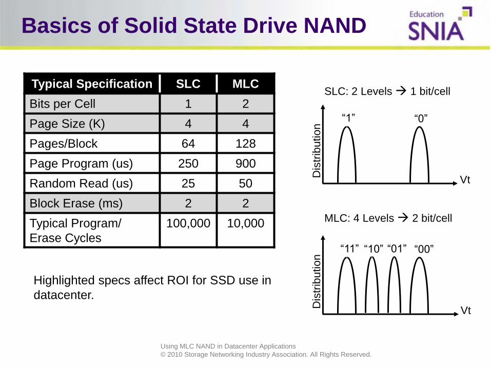
Single Level Cell (SLC): 2 voltage levels
– Level 0 = Erased = 0
– Level 1 = Programmed = 1
• Multi-Level Cell (MLC): 4 voltage levels
– Level 0 = Erased = 0
– Level 1 = Programmed to L1 = 01
– Level 2 = Programmed to L2 = 10
– Level 3 = Programmed to L3 = 11
• Others
– 2.5 bits per cell: 6 voltage levels
– 3 bits per cell: 8 voltage levels
– 4 bits per cell: 16 voltage levels
Using MLC NAND in Datacenter Applications
© 2010 Storage Networking Industry Association. All Rights Reserved.
Basics of Solid State Drive NAND
Dis
trib
ution
Vt
“1” “0”
SLC: 2 Levels 1 bit/cell
Dis
trib
ution
Vt
“11” “00”
MLC: 4 Levels 2 bit/cell
“10” “01”
Typical Specification SLC MLC
Bits per Cell 1 2
Page Size (K) 4 4
Pages/Block 64 128
Page Program (us) 250 900
Random Read (us) 25 50
Block Erase (ms) 2 2
Typical Program/
Erase Cycles
100,000 10,000
Highlighted specs affect ROI for SSD use in
datacenter.

Using MLC NAND in Datacenter Applications
© 2010 Storage Networking Industry Association. All Rights Reserved.
SLC & MLC Endurance/Lifetime
JDEC shelf life 1 year
SLC - 100,000 cycles
MLC - 10,000 cycles
Program/Erase Cycle
NAND block clear
Write amplification
Bottom Line – It depends
– Controller design
– Firmware design
– Usage Case
Dis
trib
ution
Vt
“1” “0”
SLC: 2 Levels 1 bit/cell
Dis
trib
ution
Vt
“11” “00”
MLC: 4 Levels 2 bit/cell
“10” “01”

Using MLC NAND in Datacenter Applications
© 2010 Storage Networking Industry Association. All Rights Reserved.14
What Impacts Endurance?
Managed by:
Delivers:
NAND Technologyerase cycles (SLC vs MLC )
Spare AreaCapacity reserve / work space
Write WorkloadRandom vs Sequential
Firmware AlgorithmsEfficiency of NAND writes (Write amplification) and wearleveling
Drive EnduranceDrive design and arch matters!
Lower write amplification Fewer NAND cycles Faster write perf
High Random Writes = Endurance Efficiency

Using MLC NAND in Datacenter Applications
© 2010 Storage Networking Industry Association. All Rights Reserved.
SLC / MLC
NAND moving to greater charges per cell. Greater
capacity at the expense of endurance and write speed
15
0%
10%
20%
30%
40%
50%
60%
70%
80%
90%
100%
2007 2008 2009 2010
Other
OneNAND
4 b/c
3 b/c
MLC NAND
SLC NAND

Using MLC NAND in Datacenter Applications
© 2010 Storage Networking Industry Association. All Rights Reserved.
Density
/die
Die
/Wafer
GB
/Wafer
X X X
X 2X 2X
Density
/die
Die
/Wafer
GB
/Wafer
X X X
2X X 2X
Two Ways to look at
the SLC Premium….
*Showing worst case for SLC - Actual MLC / SLC Delta ~ 80-90% assuming optimizations, timing issues, etc.
Choice of MLC vs SLC at Given Density
SLC requires an incremental 70-90% $/GB or
suppliers produce other products
300 mm
MLC or SLC
Same Cost

Using MLC NAND in Datacenter Applications
© 2010 Storage Networking Industry Association. All Rights Reserved.
Agenda
Basics of NAND technology
Basics of datacenter workloads
MLC datacenter SSD
Workload Examples
17

Using MLC NAND in Datacenter Applications
© 2010 Storage Networking Industry Association. All Rights Reserved.
Storage
Usage
Central Storage
Fab
ric (F
C a
nd
GE
/10
GE
)
Caching/
Proximity Tier
Fab
ric (F
C a
nd
GE
/10
GE
)
Server Attached
Cache Local DRAM cache:(e.g. OS block, hot
application data)
DRAM cache:
(Memcached, Storage
virtualization
appliance)
Local DRAM cache:(HDD Block Cache, Database
Cache, NFS v4 cache)
Boot Local boot data:
(SAN/NAS image)
Local boot:(Appliance image)
Local boot data when
not Pixie:(Operating System,
Hypervisor, SWAP, VM,
Application Image)
Performance Hot Application Data(Database, Email, etc)
Hot Application Data(Web, Database, Email,
Search, Videos, etc)
Capacity Cold/Luke-warm
Application Data (Data warehouse, Documents,
Backups, Archive, etc)
Luke-warm
Application Data(Web, Email, Videos, etc)
Legacy Storage in the Datacenter
18

Using MLC NAND in Datacenter Applications
© 2010 Storage Networking Industry Association. All Rights Reserved.
Storage
Usage
Central Storage
Fab
ric (F
C a
nd
GE
/10
GE
)
Caching/
Proximity Tier
Fab
ric (F
C a
nd
GE
/10
GE
)
Server/Workstation
Attached
Cache
($/IOPS,
Latency)
LBA Cache:
SAS/PCIe SSDs
(SLC)
LBA and Data
Cache:
SAS/SATA/PCIe
SSD (SLC)
LBA Cache:
SATA SSD (SLC)
Boot ($/GB) Local Boot Data:
SAS/SATA SSD
(MLC/3BC)
Local Boot Data:
SSD (MLC/3BC)
Local Boot Data when
not PXE:
SATA/SATA SSD
(MLC/3BC)
Performance
($/IOP/GB)
Hot Application Data
SAS SSDs (MLC)
Hot Application Data
SATA SSDs (MLC)
Capacity
($/TB, Watt/TB)
Cold/Luke-warm
Application Data
SATA HDDs
(future SSD 3BC/4BC?)
Luke-warm
Application DataSATA HDDs
(future SSD 3BC/4BC?)
Emerging NAND in the Datacenter
19

Using MLC NAND in Datacenter Applications
© 2010 Storage Networking Industry Association. All Rights Reserved.
The ROI Basics – SNIA TCO Calculator
For 3.5TB business intelligence database
146G 15K SAS drives (SNIA default data)
Intel® X25E 64G SLC drives (www.newegg.com 3/21/10 pricing)
Intel® X25M 160G MLC drives (www.newegg.com 3/21/10 pricing)
SNIA CO Calculator: www.snia.org/forums/sssi/programs/TCOcalc/
20

Using MLC NAND in Datacenter Applications
© 2010 Storage Networking Industry Association. All Rights Reserved.
Agenda
Basics of NAND technology
Basics of datacenter workloads
MLC datacenter SSD
Workload Examples
21

Using MLC NAND in Datacenter Applications
© 2010 Storage Networking Industry Association. All Rights Reserved.
Nuances of SSD Performance/Endurance
22
1. Type of NAND
Single Level Cell (SLC)
Multi Level Cell (MLC)
Others (2.5BC, 3BC, etc)
2. Indirection system
Erasing and Writing Blocks
3. Host traffic pattern
Workload and Fullness of SSD
4. Spare area
SSD Workspace
5. Power off shelf life

Using MLC NAND in Datacenter Applications
© 2010 Storage Networking Industry Association. All Rights Reserved.23
Nuance of the “Indirection System”
Logical to physical LBA mapping removes need for atomic operations like
read modify write (RMW)
The placement of new LBA information can be packed into pages that are at
new physical locations
Data placement in previously erased blocks makes foreground work
(Host IO operations) faster
Indirection “clean up” needs to reclaim invalid physical locations in
background
HostLogical
LBA
SSDL0 to P0
L0 to P348
L0 to P5120
SSD converts a Physical Page to Logical LBA. Logical LBA will
not reside in the same physical location each time it is written

Using MLC NAND in Datacenter Applications
© 2010 Storage Networking Industry Association. All Rights Reserved.24
Host Traffic Pattern: Empty vs Full
An empty SSDs achieves its
maximum write performance under
all workloads
Once initially filled performance will
decrease
Study State write performance is
achieved when the SSD has settled
into a consistent write latencies
pattern
A Steady State can be observed
when
User capacity is full
Consistent work load is provided
Sequential
data
Spare AreaSpare Area
SSDs steady state performance will have dependencies on
the amount of spare area

Using MLC NAND in Datacenter Applications
© 2010 Storage Networking Industry Association. All Rights Reserved.25
Host Traffic Pattern: Sequential vs Random
Steady state performance of an SSD full
of sequential data is better than the steady
state of an SSD full of random data
Sequential sectors will be invalidated in larger
linear clusters than random.
Invalidation of sectors within a block is spotty in
random writes.
Changing the workload of an SSD from
sequential to random will cause the
performance to fall whereas changing
from random to sequential will increase
performance over time.
Sequ
ential
da
ta
Random
da
ta
Spare AreaSpare Area
Valid Data
Invalid Data

Using MLC NAND in Datacenter Applications
© 2010 Storage Networking Industry Association. All Rights Reserved.26
Spare Area: The Transitory Working Space
Increasing the Spare Area helps performance by
increasing the available “ready to be written”
resource pool
Larger work space allows
for less data movement to reclaim blocks.
Less erase cycles on the blocks as we do less background
data movement
SLC already maximizes spare area
Increase MLC Performance by
Factory option - Set Max LBA to decrease user capacity and
increase Spare Area
User option - Define a partition less than the max available
capacity
Increasing spare capacity can boost performance by 10% or
more . The main benefit it allows for more consistent
performance.
Spare Area
Spare Area
Less background data movement increases performance

Using MLC NAND in Datacenter Applications
© 2010 Storage Networking Industry Association. All Rights Reserved.27
Spare Area Affects EnduranceIncreasing spare area increases endurance
Spare area beyond 27% of native capacity has diminishing returns
Adjust SSD spare area by limiting drive capacity
ATA8-ACS Host Protected Area feature set is used (SET MAX ADDRESS)
Use ATA8-ACS SECURITY ERASE UNIT prior to limiting capacity
Setting partition to smaller size after erase is an option (less robust)
SSD Technology allows adjusting capacity to provide up to 3.5X improvement in endurance
Endurance scaling w/ over provisioning
0
1
2
3
4
5
6
160 144 128Drive Capacity Utilized (GB)
No
rmal
ized
En
du
ran
ce
4KB Write 100% Random Workload
Data using Intel ®X25-MMainstream SATASolid-State Drive

Using MLC NAND in Datacenter Applications
© 2010 Storage Networking Industry Association. All Rights Reserved.
Drive Performance vs Spare Area
As spare area increases
so does performance
MLC has a greater %
performance increase
due to the relative
smaller spare area to
start with
28
0%
100%
200%
300%
400%
500%
600%
0
2000
4000
6000
8000
10000
160 144 128 96 80
IOP
S
Drive Capacity Utilized (GB)
160GB MLC Performance scaling w/ over
provisioning
IOPS
%IOPS
0%
10%
20%
30%
40%
50%
60%
70%
0100020003000400050006000700080009000
10000
64 55 45
IOP
S
Drive Capacity Utilized (GB)
64GB SLC Performance scaling w/ over provisioning
IOPS(avg)
% IOPS
IOPS scales with increase in spare area
Data using Intel ®X25-M Mainstream SATA andIntel® X25-E Extreme SATA Solid-State Drives

Using MLC NAND in Datacenter Applications
© 2010 Storage Networking Industry Association. All Rights Reserved.
Agenda
Basics of NAND technology
Basics of datacenter workloads
MLC datacenter SSD
Workload Examples
29

Using MLC NAND in Datacenter Applications
© 2010 Storage Networking Industry Association. All Rights Reserved.
0.08
0.16
0.32
0.64
1.28
2.56
5.12
10.24
20.48
40.96
81.92
163.84
64
128
256
512
1,024
2,048
4,096
8,192
16,384
32,768
65,536
131,072
262,144
8 16 32 64 128 256 512 1,024 2,048 4,096 8,192 16,384
Wri
te T
B/d
ay
pe
r A
pp
Wri
te IO
PS
(8
K a
ve
) p
er
Ap
p
GB for App
Data Access vs Storage Capacity(3 year lifetime, SLC=100K Cycles, MLC=10K Cycles, 3BC=1K Cycles)
SLC (WA=1) SLC (WA=10), MLC (WA=1) MLC (WA=10), 3BC (WA=1) 3BC (WA=10)
Mapping workloads to NAND
30

Using MLC NAND in Datacenter Applications
© 2010 Storage Networking Industry Association. All Rights Reserved.
Business Intelligence: Example
31
Business data from industry
• Digital Media
• Energy and Utilities
• Financial Services
• Health and Life Sciences
• Retail and CPG
• Telecommunications
300GB to 1PB
database
32GB to 10TB
MemoryTypically 1 core
per 32 Gig of data
Analyze… Load
Speed of result is
differentiation

Using MLC NAND in Datacenter Applications
© 2010 Storage Networking Industry Association. All Rights Reserved.32
Storage Power
x%Reduction
The Bottom Line Benefits
HDD Config:2 - 146G
15K SAS HDDs
Time to
complete
~6xDecrease
Delta$600K
Business Intelligence:
Financial services example
…20
Quad-Core processor
48G DRAM
SLC
Solution Cost
~1.5xmore
SDD Config:2 - 64G
SATA SSDs 2 – 160G
SATA SSDs (config as 146G)
MLC
Solution Cost
~1.2xmore

Using MLC NAND in Datacenter Applications
© 2010 Storage Networking Industry Association. All Rights Reserved.
Summary
Best ROI achieve by focusing on solution
MLC today for most application solutions meets
Endurance/Lifetime needs
Read/Write performance needs
MLC cost today (and likely in future)
Significantly better than 2x less in $/G
33

Using MLC NAND in Datacenter Applications
© 2010 Storage Networking Industry Association. All Rights Reserved.3434
Q&A / Feedback
Please send any questions or comments on this
presentation to SNIA: [email protected]
Many thanks to the following individuals
for their contributions to this tutorial.- SNIA Education Committee
Tony Roug


![SSD - ESOS LAB€¦ · SSD . 1 SSD Block Diagram 3.2 SSD NAND HDD . . SSD FTL . FTL NAND out-of-place update address mapping . Gabage Collection, Wear-leveling . 4. 4.1 SSD . Disksim[8]](https://static.fdocuments.in/doc/165x107/5ea6b67696cb1838a26c1ab1/ssd-esos-ssd-1-ssd-block-diagram-32-ssd-nand-hdd-ssd-ftl-ftl-nand-out-of-place.jpg)