Using GENIE E18 Motor Control Board for Project Work - t4 - Options/Control_Technology/Using... ·...
30
© t 4 Galway Education Centre 1 Using GENIE E18 Motor Control Board for Project Work
Transcript of Using GENIE E18 Motor Control Board for Project Work - t4 - Options/Control_Technology/Using... ·...

© t4 Galway Education Centre 1
Using GENIE E18 Motor
Control Board for
Project Work

© t4 Galway Education Centre 2
Foreword
The t4 Prototype Line Follower Robot has been developed as a low cost introductory model for
educators interested in Applied Control and Robotics.
Line follower robots are used extensively in industry in areas where parts or materials need to
be constantly delivered from one location to another. Generally known as AGVs (Automated
Guided Vehicles) they are found mainly in the car manufacturing industry and anywhere that
employs large warehousing where the robot follows tracks to and from the shelves they stock
and retrieve from.
This line follower robot has the following features:
One piece simple chassis easily made form acrylic sheet or even cardboard.
Low centre of gravity and moment of inertia allowing quick deceleration.
Two wheeled easily controlled differential drive and steering.
Significant distance between line sensors and wheels allowing the robot time to react
and reduce the instances of over-shooting.
Line illumination LED.
The following should be noted when using this robot:
It is not possible to program the DC motors supplied for a set number of rotations –
more expensive stepper motors would be required for this type of control. It is possible
to program the motors to turn for a set time period e.g. 1.5 seconds etc.
All the settings for the LDR sensors indicated in the notes are examples only. Each robot
will require its own settings for the sensors to be found through calibration. They will
depend on the surface it is operating on, the whiteness of the line being followed, the
charge in the batteries and indeed similar LDRs will differ slightly from each other.

© t4 Galway Education Centre 3
Table of Contents
1 Downloading/Installing GENIE Design Studio Software .................................. 4
2 GENIE Design Studio Interface ........................................................................ 5
3 Connecting the E18 Motor Control Board to your PC ........................................ 6
4 Testing the E18 Motor Control Board ............................................................... 7
5 Driving the robot forward/reverse ................................................................ 12
6 Turning the robot........................................................................................... 15
7 Using the LDRs to detect a line ...................................................................... 18
8 Using the LDRs to follow a line ...................................................................... 25
9 Using a defined loop during a program .......................................................... 27
10 GENIE Design Studio Help ............................................................................ 29
11 Useful links .................................................................................................. 30
© t4 Galway Education Centre 4
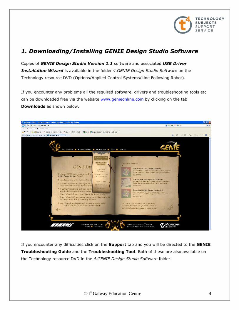
1. Downloading/Installing GENIE Design Studio Software Copies of GENIE Design Studio Version 1.1 software and associated USB Driver
Installation Wizard is available in the folder 4.GENIE Design Studio Software on the
Technology resource DVD (Options/Applied Control Systems/Line Following Robot).
If you encounter any problems all the required software, drivers and troubleshooting tools etc
can be downloaded free via the website www.genieonline.com by clicking on the tab
Downloads as shown below.
If you encounter any difficulties click on the Support tab and you will be directed to the GENIE
Troubleshooting Guide and the Troubleshooting Tool. Both of these are also available on
the Technology resource DVD in the 4.GENIE Design Studio Software folder.
© t4 Galway Education Centre 5
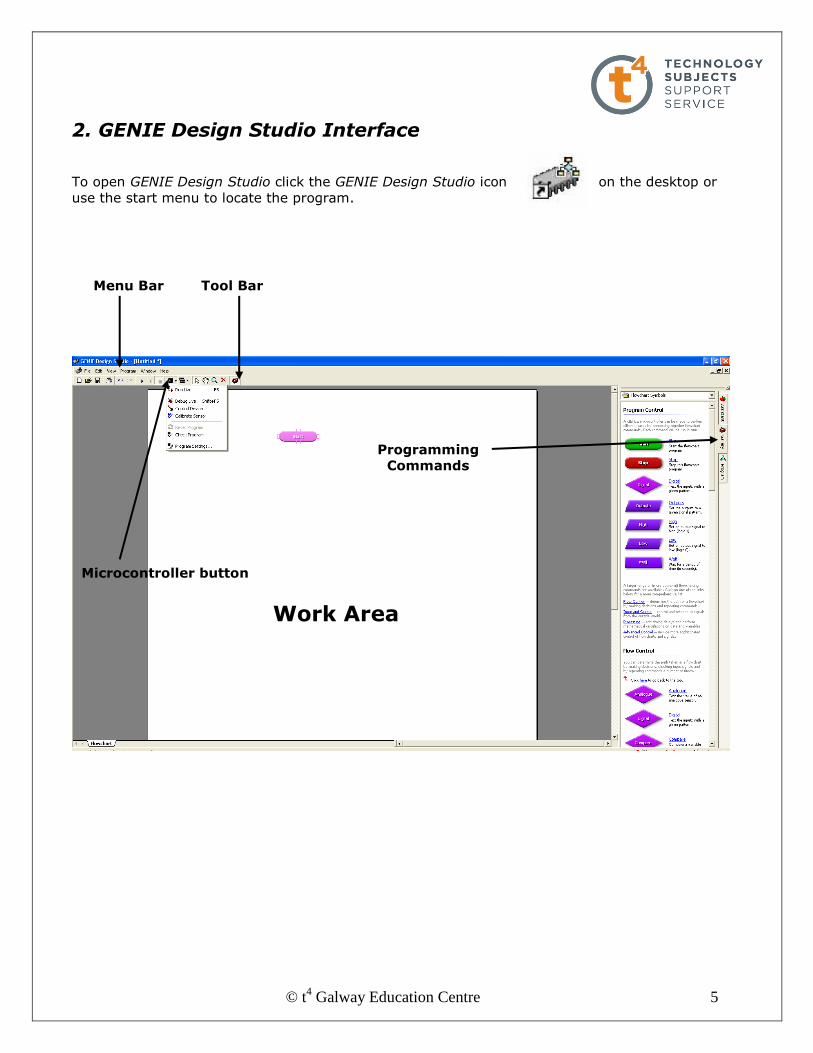
2. GENIE Design Studio Interface
To open GENIE Design Studio click the GENIE Design Studio icon on the desktop or
use the start menu to locate the program.
Menu Bar
Work Area
Tool Bar
Programming Commands
Microcontroller button
© t4 Galway Education Centre 6
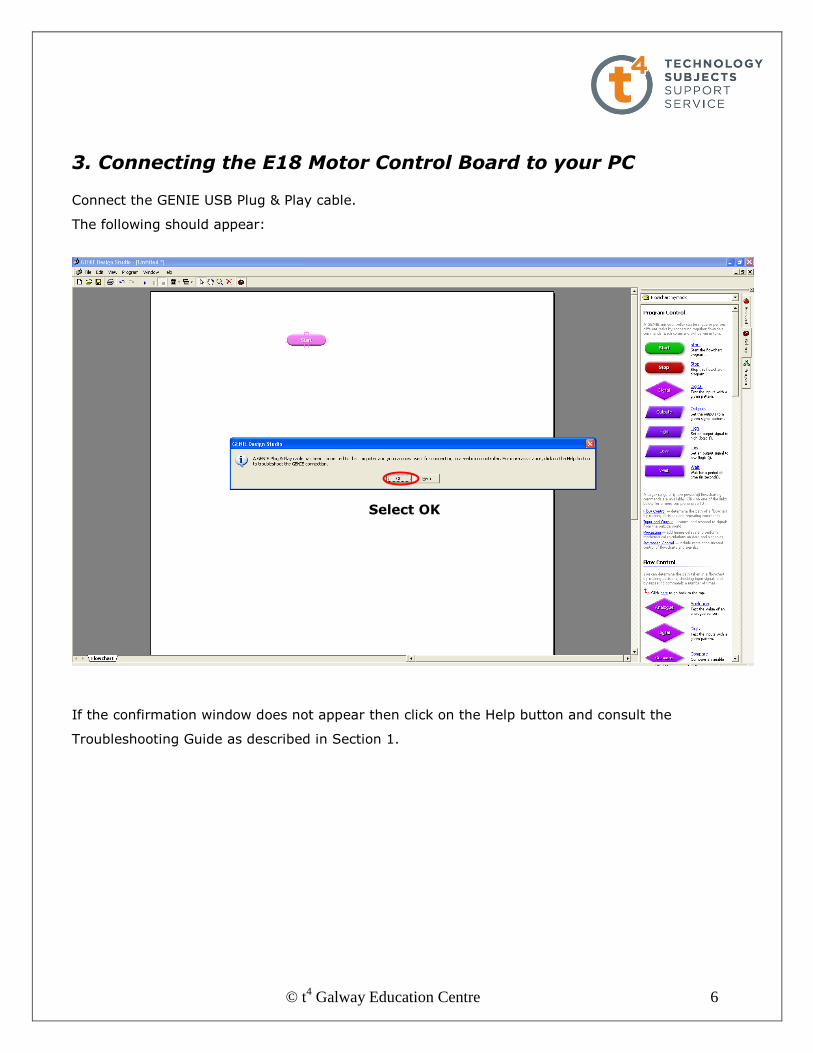
3. Connecting the E18 Motor Control Board to your PC Connect the GENIE USB Plug & Play cable.
The following should appear:
If the confirmation window does not appear then click on the Help button and consult the
Troubleshooting Guide as described in Section 1.
Select OK

© t4 Galway Education Centre 7
4. Testing the E18 Motor Control Board Firstly you must tell the software what GENIE chip you are using. Select Microcontroller from
the tool bar followed by Program Settings. Select the GENIE E18 chip.
The Program Settings window provides information about the inputs and outputs available on
the selected E18 chip:
Number of inputs and outputs available Chip configuration

© t4 Galway Education Centre 8
The E18 chip has the following features:
8 digital outputs labelled Q0 to Q7
We are only using Q3 to Q7 incl. for this line follower robot
These outputs are ‘digital’ in that they are either on (1) or off (0)
3 possible analogue inputs e.g. LDR, Thermistor etc labeled A0, A1 and A2
5 possible digital inputs e.g. switches labeled D0, D1, D2, D6 and D7
As shown on the chip configuration:
o Input A0 and D0 share Pin 17 – connected to A/D0 on PCB
o Input A1 and D1 share Pin 18 – connected to A/D1 on PCB
o Input A2 and D2 share Pin 1 – connected to A/D2 on PCB
We are only using A/D0 and A/D1 for this line follower robot
Power to the chip can be tested across Pin 5 (0v) and Pin 14 (2.5 to 5v)
It is possible to set the E18 as the default chip to be used by the software each time it is
opened. Instructions for this are available by viewing the AVI file Setting GENIE E18 chip as
default located in the folder 3.GENIE Design Studio Training for the E18 Motor Control Board.
NOTE:
We are only using LDR inputs in this
module but it is possible to use many
other analogue inputs such as a
thermistor, variable resistors etc with
the GENIE E18.
Similarly it is possible to incorporate
digital inputs such as micro switches
with the robot for obstacle avoidance
etc but they are not covered in this module.

© t4 Galway Education Centre 9
Connect the GENIE USB Plug & Play cable to the line follower robot and turn on power to the
robot using the SPST switch on board.
The green status LED should flash and the software should indicate
that the microcontroller is now connected as shown.
We can now test that both motors and the line illumination LED are
working.
We will use the Control Device command to test these outputs. This command can be
activated from the menu shown above or by clicking the Microcontroller button on the tool
bar as shown below.

© t4 Galway Education Centre 10
Activating the Control Device command opens the following window in the Program menu.
By clicking on output Q3 and changing it from off (0) to on (1) we should be able to activate
the line illumination LED at the front of the line follower robot as shown.
If the LED does not illuminate, check the following:
Is the solderless LED holder connected into the PCB with
correct polarity as shown below?
Is the Solderless LED connected to the LED with correct
polarity i.e. leg on flat side of LED connected into negative
black?
This indicates that the software recognises that A/D0 and A/D1 inputs are connected
This indicates that all outputs are currently off (0)

© t4 Galway Education Centre 11
Now, by turning on (1) and off (0) outputs Q7, Q6, Q5 and Q4 in turn, we should observe the
clockwise and anticlockwise rotation of each motor M4 and M3.
If the motors do not operate then check the following:
Are the 2 cables from M4 connected into Q6 and Q7 on the PCB?
Are the 2 cables from M3 connected into Q4 and Q5 on the PCB?
In the next section we will now look at how to write a simple program to operate both motors in
order to create forward and reverse motion.
© t4 Galway Education Centre 12
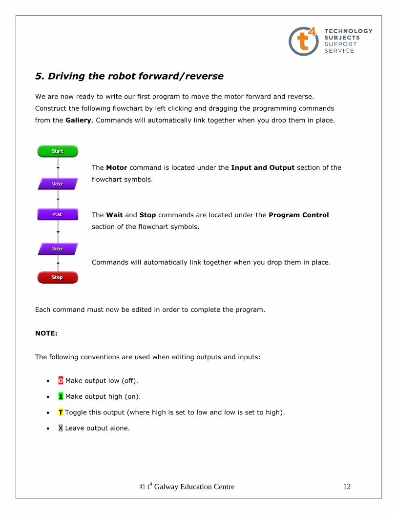
5. Driving the robot forward/reverse We are now ready to write our first program to move the motor forward and reverse.
Construct the following flowchart by left clicking and dragging the programming commands
from the Gallery. Commands will automatically link together when you drop them in place.
The Motor command is located under the Input and Output section of the
flowchart symbols.
The Wait and Stop commands are located under the Program Control
section of the flowchart symbols.
Commands will automatically link together when you drop them in place.
Each command must now be edited in order to complete the program.
NOTE:
The following conventions are used when editing outputs and inputs:
0 Make output low (off).
1 Make output high (on).
T Toggle this output (where high is set to low and low is set to high).
X Leave output alone.
© t4 Galway Education Centre 13
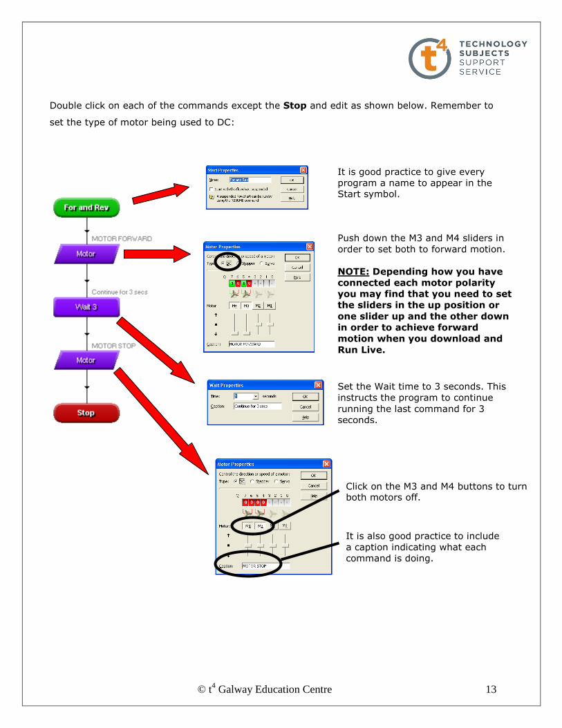
Double click on each of the commands except the Stop and edit as shown below. Remember to
set the type of motor being used to DC:
It is good practice to give every
program a name to appear in the Start symbol.
Push down the M3 and M4 sliders in
order to set both to forward motion.
NOTE: Depending how you have
connected each motor polarity
you may find that you need to set
the sliders in the up position or
one slider up and the other down
in order to achieve forward
motion when you download and
Run Live.
Set the Wait time to 3 seconds. This
instructs the program to continue
running the last command for 3
seconds.
Click on the M3 and M4 buttons to turn both motors off.
It is also good practice to include
a caption indicating what each
command is doing.
© t4 Galway Education Centre 14
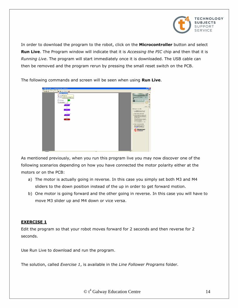
In order to download the program to the robot, click on the Microcontroller button and select
Run Live. The Program window will indicate that it is Accessing the PIC chip and then that it is
Running Live. The program will start immediately once it is downloaded. The USB cable can
then be removed and the program rerun by pressing the small reset switch on the PCB.
The following commands and screen will be seen when using Run Live.
As mentioned previously, when you run this program live you may now discover one of the
following scenarios depending on how you have connected the motor polarity either at the
motors or on the PCB:
a) The motor is actually going in reverse. In this case you simply set both M3 and M4
sliders to the down position instead of the up in order to get forward motion.
b) One motor is going forward and the other going in reverse. In this case you will have to
move M3 slider up and M4 down or vice versa.
EXERCISE 1
Edit the program so that your robot moves forward for 2 seconds and then reverse for 2
seconds.
Use Run Live to download and run the program.
The solution, called Exercise 1, is available in the Line Follower Programs folder.

© t4 Galway Education Centre 15
6. Turning the robot
The procedure for turning the robot while it is moving is based simply on turning off one motor
and leaving the other running.
Construct and edit the following flowchart as shown. Settings for motor control are shown.
You will see these output
settings appear in the
Multiple Panel View when we simulate this program.

© t4 Galway Education Centre 16
Select the Run command on the tool bar.
You will see each flowchart command highlight as the
program simulates.
The Speed Dial can be rotated to adjust the speed at which the simulation runs.
Now click on the View several monitor panels at once
command in order to open Multiple Panel View.
This allows us see what each flowchart command is doing as
shown below.
To turn right motor M3 is turned
off by turning off both outputs
Q4 and Q5 and motor M4 is left
running (output Q7) in forward
direction.
We created this setting earlier
while editing this command
using Motor Properties.

© t4 Galway Education Centre 17
Click on the Microcontroller button and select Run Live in order to download the program to
the robot. The Program window will indicate that it is Accessing the PIC chip and then that it is
Running Live. The program will start immediately once it is downloaded. The USB cable can
then be removed and the program re-run by pressing the small reset switch on the PCB.
EXERCISE 2
Like all learner drivers you need to learn how to complete a 3 point turn.
Edit the previous Turning Ex program to have your robot execute a 3 point turn.
One possible solution, called Exercise 2 Three Point Turn, is available in the Line Follower
Programs folder.
Points to consider:
There are numerous solutions to this exercise.
Ensure your wheels are tightened on to the motor shaft to ensure proper movement.
It is not possible to control the number of revolutions of a DC motor as it is with a servo
or stepper motor.
Controlling the amount your robot turns using the Wait command is accomplished by
trial and error.
It is possible to set the Wait Properties to fractions of seconds by typing the value in
rather than selecting the set values from the drop down menu as shown below.
The turning circle of a robot such as this depends on the diameter of the wheel and the
distance between the wheel centres. This could be the basis for an applied maths
question for your students.
Having completed this exercise why not try to program your robot to drive in a square, drive in
a figure 8 or even set up a parking bay that it must park in using parallel parking!
© t4 Galway Education Centre 18
7. Using the LDRs to detect a line. Before we can successfully use the LDR to detect a line we must learn how to understand the
digital reading that the LDR creates in the software.
The resistance of the miniature LDR supplied goes from approx 1KΩ in normal light to approx
15KΩ in normal darkness i.e. it’s resistance increases as it gets darker.
Theoretically it goes from 0KΩ in total brightness to 1MΩ in total darkness.
The GENIE software takes whatever analogue resistance value the LDR has at any given
moment and converts it into a digital reading of between 0 and 255.
A digital value of 0 corresponds to an LDR resistance of 1MΩ i.e. total darkness.
Similarly, a digital reading of 255 corresponds to an LDR resistance of 0KΩ i.e. total brightness.
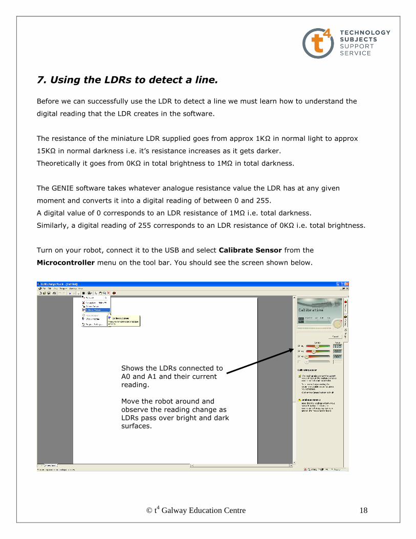
Turn on your robot, connect it to the USB and select Calibrate Sensor from the
Microcontroller menu on the tool bar. You should see the screen shown below.
Shows the LDRs connected to
A0 and A1 and their current
reading.
Move the robot around and
observe the reading change as
LDRs pass over bright and dark surfaces.
© t4 Galway Education Centre 19
The area underneath the LDRs on the robot will, by virtue of its design, be quite dark. This
could create difficulties when trying to detect a white line on a dark surface. In order to solve
this problem a LED has been installed between them to illuminate the line and surface.
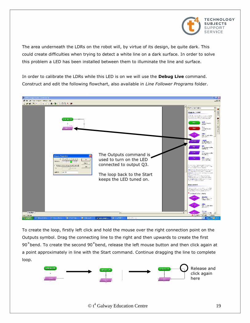
In order to calibrate the LDRs while this LED is on we will use the Debug Live command.
Construct and edit the following flowchart, also available in Line Follower Programs folder.
To create the loop, firstly left click and hold the mouse over the right connection point on the
Outputs symbol. Drag the connecting line to the right and then upwards to create the first
90˚bend. To create the second 90˚bend, release the left mouse button and then click again at
a point approximately in line with the Start command. Continue dragging the line to complete
loop.
The Outputs command is
used to turn on the LED
connected to output Q3.
The loop back to the Start keeps the LED tuned on.
Release and
click again
here

© t4 Galway Education Centre 20
Place your robot on a dark surface, in order to create a contrast with the masking tape line
later, turn on and select Debug Live from the Microcontroller menu. You will see the screen
shown below.
Click Start to begin Debug Live. This facility allows you watch your program animate as it
runs live on the microcontroller.
By clicking on View several monitor panels at once as shown below we can now observe
what the LDRs are reading along with what inputs/outputs etc are activated.
You could choose to view the inputs/outputs or the analogue
sensor readings etc on their own but the View several monitor
panels at once option shows nearly everything and is
demonstrated on the following page.
© t4 Galway Education Centre 21
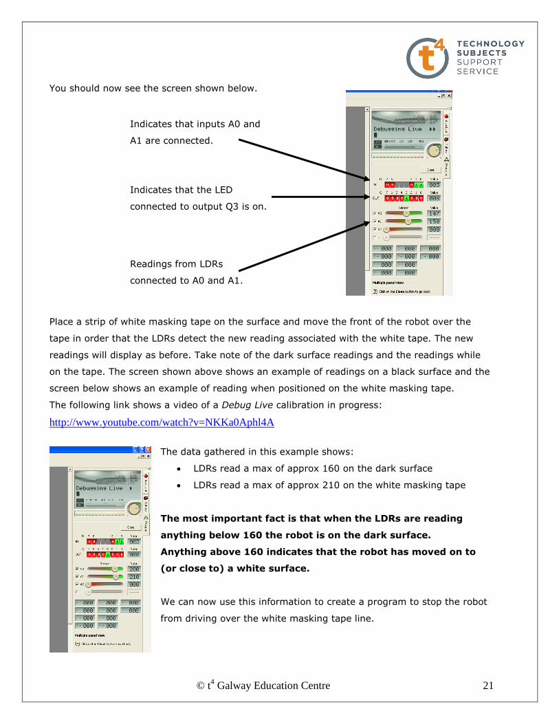
You should now see the screen shown below.
Place a strip of white masking tape on the surface and move the front of the robot over the
tape in order that the LDRs detect the new reading associated with the white tape. The new
readings will display as before. Take note of the dark surface readings and the readings while
on the tape. The screen shown above shows an example of readings on a black surface and the
screen below shows an example of reading when positioned on the white masking tape.
The following link shows a video of a Debug Live calibration in progress:
http://www.youtube.com/watch?v=NKKa0Aphl4A
The data gathered in this example shows:
LDRs read a max of approx 160 on the dark surface
LDRs read a max of approx 210 on the white masking tape
The most important fact is that when the LDRs are reading
anything below 160 the robot is on the dark surface.
Anything above 160 indicates that the robot has moved on to
(or close to) a white surface.
We can now use this information to create a program to stop the robot
from driving over the white masking tape line.
Indicates that inputs A0 and
A1 are connected.
Indicates that the LED
connected to output Q3 is on.
Readings from LDRs
connected to A0 and A1.
© t4 Galway Education Centre 22
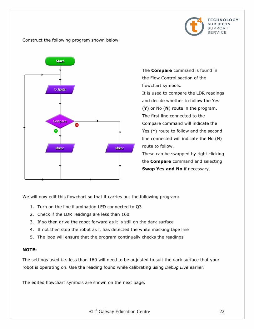
Construct the following program shown below.
The Compare command is found in
the Flow Control section of the
flowchart symbols.
It is used to compare the LDR readings
and decide whether to follow the Yes
(Y) or No (N) route in the program.
The first line connected to the
Compare command will indicate the
Yes (Y) route to follow and the second
line connected will indicate the No (N)
route to follow.
These can be swapped by right clicking
the Compare command and selecting
Swap Yes and No if necessary.
We will now edit this flowchart so that it carries out the following program:
1. Turn on the line illumination LED connected to Q3
2. Check if the LDR readings are less than 160
3. If so then drive the robot forward as it is still on the dark surface
4. If not then stop the robot as it has detected the white masking tape line
5. The loop will ensure that the program continually checks the readings
NOTE:
The settings used i.e. less than 160 will need to be adjusted to suit the dark surface that your
robot is operating on. Use the reading found while calibrating using Debug Live earlier.
The edited flowchart symbols are shown on the next page.

© t4 Galway Education Centre 23
NOTE:
Remember to use your own readings that you found earlier while calibrating during Debug Live.
Tick the and box to open the second expression.
This instructs the program to compare both readings from A0
and A1 to see if they are less than 160. If they are, then the robot is still
on the dark surface and continues forward. If they are more than 160 the robot has encountered the white line and stops.

© t4 Galway Education Centre 24
EXERCISE 3
Mark out an enclosed area on a floor using the white masking tape inside which the robot will
be free to maneuver.
Edit the previous program Detect White Line so that the robot remains inside the marked area.
One possible solution, called Exercise 3 Staying Inside Area, is available in the Line Follower
Programs folder.
Points to consider:
There are a number of solutions to this exercise.
Ensure your wheels are tightened on to the motor shaft to ensure proper movement.
You may have to recalibrate the LDRs with the LED activated using Debug Live if the
floor area you are using is a lot darker or brighter than the area you used for the
previous program Detect White Line.
Click on the following link to see a video of the robot carrying out this exercise:
http://www.youtube.com/watch?v=GiHYn9ch-vs

© t4 Galway Education Centre 25
8. Using the LDRs to follow a line
Construct and edit the program shown below.
NOTE:
In the first Compare command the LDRs are set so that if they both read more than
160 i.e. they are both detecting the white masking tape then both motors are on moving
the robot forward.
In the second Compare command if A1 reads less than 160 then the robot has moved
off the line to the left and motor M3 is turned off in order to move the robot to the right
and back to the line.
In the third Compare command if A0 reads less than 160 then the robot has moved off
the line to the right and motor M4 is turned off in order to move the robot to the left and
back to the line.

© t4 Galway Education Centre 26
Mark out a line on the floor using the masking tape. Include curves and 90˚bends in the line.
Turn on your robot, connect via USB and select Run Live to download this program Line
Follower 1. A copy of the program is also available in the Line Follower Programs folder.
Turn off, disconnect your robot from the USB and set it up at the start of the line. Turn on and
observe how well it follows the line.
Points to consider:
Ensure your wheels are tightened on to the motor shaft to ensure proper movement.
You may have to recalibrate the LDRs with the LED activated using Debug Live if the
floor area you are using is a lot darker or brighter than the area you used previously.
Click on the following link to see a video of the robot carrying out this exercise:
http://www.youtube.com/watch?v=VHkEDG8Q42E
Note how the program is able to deal with the first 90˚right bend but unable to deal with the
second 90˚left bend!
In the next section we will look at one possible way of dealing with this problem.

© t4 Galway Education Centre 27
9. Using a defined loop during a program
In order to deal with the problem encountered during the previous exercise of the robot losing
sight of the line, we need to program it to look for the line. This is best accomplished by
inserting a loop in the program that will instruct the robot to firstly look left and if it does not
find the line there, to then look right until it does.
Edit the previous program to create the following flowchart. As you will see in the video later,
we are using a different surface and so we will look at the initial LDR settings before moving on
to look at the defined loop in detail.
Apart from new LDR settings these parts of the flowchart are the same as in Line Follower 1.
The motors are programmed as before with either M3 or M4 off if A1 or A0 moves off the line
and both on while A0 and A1 are on the line. We will now look at the new loop in the program.
Having placed the robot on a new
surface we carried out calibration
using Debug Live.
The readings show that A0 is on the
line when the reading is greater
than 150 and A1 is on the line when
reading is greater than 160.
NOTE: Remember to find and use your own calibration readings.
© t4 Galway Education Centre 28
We will now look at what happens when A0 reads less than 150 and A1 reads less than 160
meaning that both LDRs have moved off the line.
In this section of the program the robot is initially looking left for the line and if it is not found
after 1 second (approx a 90˚ turn) it looks right continuously until it is found. Depending on the
layout of the line being followed the time of the initial loop may need to be extended. A copy of
the program is also available in the Line Follower Programs folder. Click on the following link to
see a video of the robot carrying out this exercise:
http://www.youtube.com/watch?v=aV4oSjNv8VM
Once the program detects that the sensors A1 and A0 are
both off the line the motor stops briefly for half a second. This minimises the amount of over-shoot of the line.
The For command is found in
the Flow Control section of the
flowchart symbols. It runs the
series of commands between it
and the End Loop command
either a set number of times or
for a given number of seconds –
in this case, for 1 second.
The Motor command that
follows causes the robot to
perform a two wheeled left turn
in order to look for the line.
The Compare command checks
to see either if A0 or A1 are on
the line during the left turn. If
they are then the program
follows the Y route back to the
main section of the program.
If not, after the 1 second loop
ends, the motor performs a two
wheeled right turn continuously
until a further Compare
command detects the line in the
other direction. When it does
the program follows the Y route
back to the main section of the
program.

© t4 Galway Education Centre 29
10. GENIE Design Studio Help These notes are only an introduction to GENIE Design Studio. It contains many more
commands that have not been mentioned at all.
Explanations of these other commands can be found in the Help section of the software by
clicking on GENIE Design Studio Help as shown below:
Then select Flowchart commands as shown:
This will open a window displaying all current GENIE commands. By clicking on any command
the user will be given a simple explanation of what the command does along with a sample
flowchart showing how the command may be used.
© t4 Galway Education Centre 30
10. Useful links
The following is a sample of websites that may be useful for further study in the area of PIC
microcontrollers:
http://www.genieonline.com/
http://www.rev-ed.co.uk/
http://www.picaxeforum.co.uk/
http://www.logicator.co.uk/
http://www.technologystudent.com/pics/picdex1.htm
http://www.ajbox.co.uk/
http://www.new-wave-concepts.com/
http://www.youtube.com/watch?v=u4Ia_YRUCy0
http://www.t4.ie/Professional_Development/RD8_Technology/Robotics/A%20Guideline
%20to%20using%20%20Pic%20Logicator.pdf
http://www.economatics-education.co.uk/secondary/education/90,94,0/1536/PIC-
Logicator_Version_2.htm
http://www.bbc.co.uk/science/robots/techlab/sub_selector.shtml