
Using AT RUN, Setting up Digital Voice Guide - Multi-Tech€¦ · SGSN Serving GPRS Support Node...
63
Configuring H5 Devices Using AT RUN, Setting up Digital Voice Interface and Configuring Ports Reference Guide
Transcript of Using AT RUN, Setting up Digital Voice Guide - Multi-Tech€¦ · SGSN Serving GPRS Support Node...
Configuring H5 Devices Using AT RUN, Setting up Digital Voice Interface and Configuring Ports Reference Guide
Using AT RUN, Setting up Digital Voice Interface and Configuring Ports Reference Guide 2
H5 AT Commands Reference Guide for the following products: MTSMC-H5-xx, MTPCIE-H5-xx, MTC-H5-xx, MTR-H5-xx, MTRZ-H5-xx, MTCMR-H5-xx, MT100UCC-H5-xx, MT100EOCG-H5-xx, MTCDP-H5-xx, MTD-H5-xx Part Number S000552A, Revision A
Copyright This publication may not be reproduced, in whole or in part, without prior expressed written permission from Multi-Tech Systems, Inc. All rights reserved. Copyright © 2012, by Multi-Tech Systems, Inc.
Multi-Tech Systems, Inc. makes no representations or warranty with respect to the contents hereof and specifically disclaim any implied warranties of merchantability or fitness for any particular purpose. Furthermore, Multi-Tech Systems, Inc. reserves the right to revise this publication and to make changes from time to time in the content hereof without obligation of Multi-Tech Systems, Inc. to notify any person or organization of such revisions or changes.
Revisions
Revision Level Date Description
A 11/28/12 Initial release.
Trademarks Multi-Tech and the Multi-Tech logo are registered trademarks of Multi-Tech Systems, Inc.
Contacting Multi-Tech Knowledge Base
The Knowledge Base provides immediate access to support information and resolutions for all Multi-Tech products. Visit http://www.multitech.com/kb.go.
Support Portal To create an account and submit a support case directly to our technical support team, visit: https://support.multitech.com
Technical Support Business Hours: M-F, 9am to 5pm CT
Country By Email By Phone
Europe, Middle East, Africa: [email protected] +(44) 118 959 7774
U.S., Canada, all others: [email protected] (800) 972-2439 or (763) 717-5863
World Headquarters Multi-Tech Systems, Inc. 2205 Woodale Drive Mounds View, Minnesota 55112 Phone: 763-785-3500 or 800-328-9717 Fax: 763-785-9874
Warranty To read the warranty statement for your product, please visit: http://www.multitech.com/warranty.go.
CONTENTS
Using AT RUN, Setting up Digital Voice Interface and Configuring Ports Reference Guide 3
Contents Document Overview .................................................................................................................................................... 5
Abbreviations and acronyms .............................................................................................................................................. 5
Using AT Run Services and Event Monitor Services ....................................................................................................... 6
AT Run Services Overview ................................................................................................................................................... 6
SMS AT Run Service Overview .......................................................................................................................................................... 8
TCP AT Run Service Overview ........................................................................................................................................................... 9
Event Monitor Service Overview ...................................................................................................................................... 12
Configuring Event Monitor Service ................................................................................................................................................. 12
AT Command Log to H5 .................................................................................................................................................................. 12
Using the Digital Voice Interface ................................................................................................................................ 13
Overview of Where and How Digital Voice Interface is Used ........................................................................................... 13
DVI Overview .................................................................................................................................................................................. 13
DVI Configurations .......................................................................................................................................................................... 14
Application Examples ........................................................................................................................................................ 15
Normal Mode (I2S) .......................................................................................................................................................................... 16
Module is Slave ............................................................................................................................................................................... 19
Burst Mode (PCM) ............................................................................................................................................................. 21
Module is Master ............................................................................................................................................................................ 21
Module is Slave ............................................................................................................................................................................... 24
I2S Overview ...................................................................................................................................................................... 26
DVI Timings ....................................................................................................................................................................... 28
Normal Master Mode ..................................................................................................................................................................... 28
Normal Master Mode Parameters .................................................................................................................................................. 28
Normal Slave Mode ......................................................................................................................................................................... 29
PCM Master Mode .......................................................................................................................................................................... 30
PCM Slave Mode ............................................................................................................................................................................. 31
Schematic .......................................................................................................................................................................... 31
Arranging Ports and Avoiding Contended Resources .................................................................................................. 33
Port Arrangements and Virtual Serial Device ................................................................................................................... 33
Factory Ports Arrangement with no USB cable ................................................................................................................. 36
Factory Ports Arrangement with USB cable ...................................................................................................................... 39
GPS/NMEA sentences on USB0 ....................................................................................................................................................... 40
AT#PORTCFG Command ................................................................................................................................................................. 41
USIF0 and AT+CMUX Command ....................................................................................................................................... 52
USB and AT+CMUX Command .......................................................................................................................................... 55
CONTENTS
Using AT RUN, Setting up Digital Voice Interface and Configuring Ports Reference Guide 4
GPS/NMEA sentences on USB3-VC3 ............................................................................................................................................... 57
The Successful Ports Configuration ................................................................................................................................... 58
Example 1 ........................................................................................................................................................................................ 59
Example 2 ........................................................................................................................................................................................ 59
Services ............................................................................................................................................................................. 60
Python ............................................................................................................................................................................................. 60
Python Script Debugging ................................................................................................................................................................. 63
DOCUMENT OVERVIEW
Using AT RUN, Setting up Digital Voice Interface and Configuring Ports Reference Guide 5
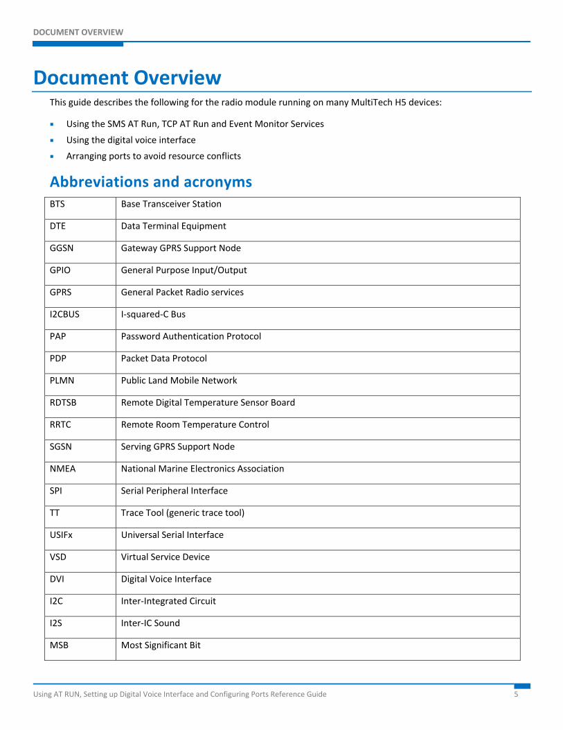
Document Overview This guide describes the following for the radio module running on many MultiTech H5 devices:
Using the SMS AT Run, TCP AT Run and Event Monitor Services
Using the digital voice interface
Arranging ports to avoid resource conflicts
Abbreviations and acronyms BTS Base Transceiver Station
DTE Data Terminal Equipment
GGSN Gateway GPRS Support Node
GPIO General Purpose Input/Output
GPRS General Packet Radio services
I2CBUS I-squared-C Bus
PAP Password Authentication Protocol
PDP Packet Data Protocol
PLMN Public Land Mobile Network
RDTSB Remote Digital Temperature Sensor Board
RRTC Remote Room Temperature Control
SGSN Serving GPRS Support Node
NMEA National Marine Electronics Association
SPI Serial Peripheral Interface
TT Trace Tool (generic trace tool)
USIFx Universal Serial Interface
VSD Virtual Service Device
DVI Digital Voice Interface
I2C Inter-Integrated Circuit
I2S Inter-IC Sound
MSB Most Significant Bit
USING SMS AT RUN, TCP AT RUN AND EVENT MONITOR SERVICES
Using AT RUN, Setting up Digital Voice Interface and Configuring Ports Reference Guide 6
Using AT Run Services and Event Monitor Services This section describes how to use the AT Run services (SMS AT Run, TCP AT Run) and Event Monitor services.
The following models support these services:
MTSMC-H5 (non UIP) MTSMC-EV3-N2 (non UIP) MTSMC-EV3-N3 (non UIP)
MTSMC-EV3-N16 (non UIP) MTSMC-G3 (non UIP) MTSMC-C2-N2 (non UIP)
MTSMC-C2-N3 (non UIP) MTSMC-C2-N16 (non UIP) MTSMC-Telit-UIP
MT100UCC-H5 MT100UCC-EV3-N2 MT100UCC-EV3-N3
MT100UCC-EV3-N16 MTCBA-H5-EN2 MTCMR-H5
MTCMR-EV3-N2 MTCMR-EV3-N3 MTCMR-EV3-N16
MTCMR-C2-N2 MTCMR-C2-N3 MTCMR-C2-N16
MT100EOCG-H5 MT100EOCG-EV3-N2 MT100EOCG-EV3-N3
MT100EOCG-EV3-N16 MTCDP-H5 Physio-EV3-N3
MTPCIE-H5 and MTPCIE-DK1 MTPCIE-EV3-N2 MTPCIE-EV3-N3
MTPCIE-EV3-N16 MTD-H5-Bxx MTD-EV3-Bxx-N2
MTD-EV3-Bxx-N3 MTD-EV3-Bxx-N16 MTOCGD3/MTOCGD2-H5
MTOCGD3/MTOCGD2-EV3-N2 MTOCGD3/MTOCGD2-EV3-N3 MTOCGD3/MTOCGD2-EV3-N16
MTC-H5-Bxx MTC-EV3-Bxx-N2 MTC-EV3-Bxx-N3
MTC-EV3-Bxx-N16 MTC-G3-Bxx MTC-C2-Bxx-N2
MTC-C2-Bxx-N3 MTC-C2-Bxx-N16
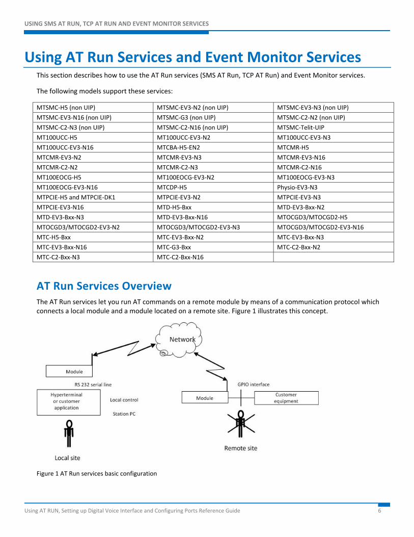
AT Run Services Overview The AT Run services let you run AT commands on a remote module by means of a communication protocol which connects a local module and a module located on a remote site. Figure 1 illustrates this concept.
Figure 1 AT Run services basic configuration
USING SMS AT RUN, TCP AT RUN AND EVENT MONITOR SERVICE
Using AT RUN, Setting up Digital Voice Interface and Configuring Ports Reference Guide 7
The modules provide the following types of AT Run services:
SMS AT Run service:
Simple SMS AT Run service
Digest SMS AT Run service
You can use the SMS AT Run service in GSM mode or in GPRS mode. For GPRS, the network operator must support SMS.
TCP AT Run service
Client mode
Server (listen) mode
Note: The Event Monitor service provided by the module lets you associate an AT command with a specified event monitored by the module itself. When the module recognizes the event occurring, it executes the associated AT command. You can use the Event Monitor service jointly with the AT Run services. For further information about the Event Monitor service, see the section “
USING SMS AT RUN, TCP AT RUN AND EVENT MONITOR SERVICE
Using AT RUN, Setting up Digital Voice Interface and Configuring Ports Reference Guide 8
Event Monitor Service Overview” in this guide.
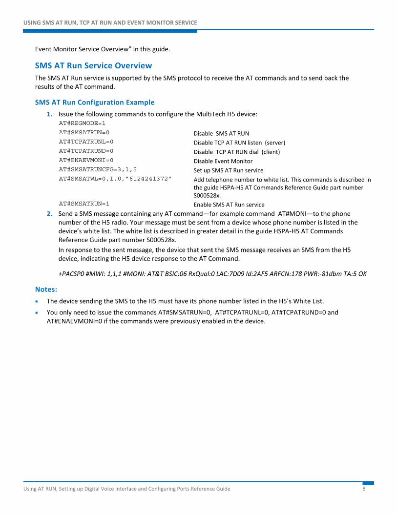
SMS AT Run Service Overview The SMS AT Run service is supported by the SMS protocol to receive the AT commands and to send back the results of the AT command.
SMS AT Run Configuration Example
1. Issue the following commands to configure the MultiTech H5 device: AT#REGMODE=1 AT#SMSATRUN=0 Disable SMS AT RUN AT#TCPATRUNL=0 Disable TCP AT RUN listen (server) AT#TCPATRUND=0 Disable TCP AT RUN dial (client) AT#ENAEVMONI=0 Disable Event Monitor AT#SMSATRUNCFG=3,1,5 Set up SMS AT Run service AT#SMSATWL=0,1,0,”6124241372” Add telephone number to white list. This commands is described in
the guide HSPA-H5 AT Commands Reference Guide part number S000528x.
AT#SMSATRUN=1 Enable SMS AT Run service 2. Send a SMS message containing any AT command—for example command AT#MONI—to the phone
number of the H5 radio. Your message must be sent from a device whose phone number is listed in the device’s white list. The white list is described in greater detail in the guide HSPA-H5 AT Commands Reference Guide part number S000528x. In response to the sent message, the device that sent the SMS message receives an SMS from the H5 device, indicating the H5 device response to the AT Command.
+PACSP0 #MWI: 1,1,1 #MONI: AT&T BSIC:06 RxQual:0 LAC:7D09 Id:2AF5 ARFCN:178 PWR:-81dbm TA:5 OK
Notes:
The device sending the SMS to the H5 must have its phone number listed in the H5’s White List.
You only need to issue the commands AT#SMSATRUN=0, AT#TCPATRUNL=0, AT#TCPATRUND=0 and AT#ENAEVMONI=0 if the commands were previously enabled in the device.
USING SMS AT RUN, TCP AT RUN AND EVENT MONITOR SERVICE
Using AT RUN, Setting up Digital Voice Interface and Configuring Ports Reference Guide 9
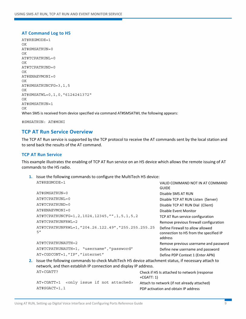
AT Command Log to H5 AT#REGMODE=1 OK AT#SMSATRUN=0 OK AT#TCPATRUNL=0 OK AT#TCPATRUND=0 OK AT#ENAEVMONI=0 OK AT#SMSATRUNCFG=3,1,5 OK AT#SMSATWL=0,1,0,"6124241372" OK AT#SMSATRUN=1 OK When SMS is received from device specified via command AT#SMSATWL the following appears:
#SMSATRUN: AT#MONI
TCP AT Run Service Overview The TCP AT Run service is supported by the TCP protocol to receive the AT commands sent by the local station and to send back the results of the AT command.
TCP AT Run Service
This example illustrates the enabling of TCP AT Run service on an H5 device which allows the remote issuing of AT commands to the H5 radio.
1. Issue the following commands to configure the MultiTech H5 device: AT#REGMODE=1 VALID COMMAND NOT IN AT COMMAND
GUIDE AT#SMSATRUN=0 Disable SMS AT RUN AT#TCPATRUNL=0 Disable TCP AT RUN Listen (Server) AT#TCPATRUND=0 Disable TCP AT RUN Dial (Client) AT#ENAEVMONI=0 Disable Event Monitor AT#TCPATRUNCFG=1,2,1024,12345,””,1,5,1,5,2 TCP AT Run service configuration AT#TCPATRUNFRWL=2 Remove previous firewall configuration AT#TCPATRUNFRWL=1,”204.26.122.49”,”255.255.255.255”
Define Firewall to allow allowed connection to H5 from the specified IP address
AT#TCPATRUNAUTH=2 Remove previous username and password AT#TCPATRUNAUTH=1, “username”,”password” Define new username and password AT+CGDCONT=1,”IP”,”internet” Define PDP Context 1 (Enter APN)
2. Issue the following commands to check MultiTech H5 device attachment status, if necessary attach to network, and then establish IP connection and display IP address. AT+CGATT? Check if H5 Is attached to network (response
+CGATT: 1) AT+CGATT=1 <only issue if not attached> Attach to network (if not already attached) AT#SGACT=1,1 PDP activation and obtain IP address
USING SMS AT RUN, TCP AT RUN AND EVENT MONITOR SERVICE
Using AT RUN, Setting up Digital Voice Interface and Configuring Ports Reference Guide 10
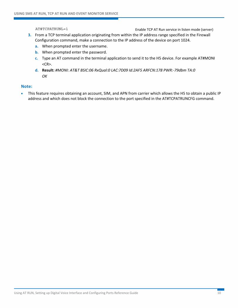
AT#TCPATRUNL=1 Enable TCP AT Run service in listen mode (server) 3. From a TCP terminal application originating from within the IP address range specified in the Firewall
Configuration command, make a connection to the IP address of the device on port 1024. a. When prompted enter the username. b. When prompted enter the password. c. Type an AT command in the terminal application to send it to the H5 device. For example AT#MONI
<CR>. d. Result: #MONI: AT&T BSIC:06 RxQual:0 LAC:7D09 Id:2AF5 ARFCN:178 PWR:-79dbm TA:0
OK
Note:
This feature requires obtaining an account, SIM, and APN from carrier which allows the H5 to obtain a public IP address and which does not block the connection to the port specified in the AT#TCPATRUNCFG command.
USING SMS AT RUN, TCP AT RUN AND EVENT MONITOR SERVICE
Using AT RUN, Setting up Digital Voice Interface and Configuring Ports Reference Guide 11
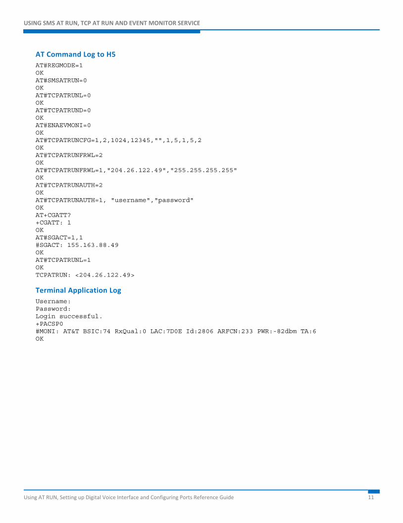
AT Command Log to H5 AT#REGMODE=1 OK AT#SMSATRUN=0 OK AT#TCPATRUNL=0 OK AT#TCPATRUND=0 OK AT#ENAEVMONI=0 OK AT#TCPATRUNCFG=1,2,1024,12345,"",1,5,1,5,2 OK AT#TCPATRUNFRWL=2 OK AT#TCPATRUNFRWL=1,"204.26.122.49","255.255.255.255" OK AT#TCPATRUNAUTH=2 OK AT#TCPATRUNAUTH=1, "username","password" OK AT+CGATT? +CGATT: 1 OK AT#SGACT=1,1 #SGACT: 155.163.88.49 OK AT#TCPATRUNL=1 OK TCPATRUN: <204.26.122.49>
Terminal Application Log Username: Password: Login successful. +PACSP0 #MONI: AT&T BSIC:74 RxQual:0 LAC:7D0E Id:2806 ARFCN:233 PWR:-82dbm TA:6 OK
USING SMS AT RUN, TCP AT RUN AND EVENT MONITOR SERVICE
Using AT RUN, Setting up Digital Voice Interface and Configuring Ports Reference Guide 12
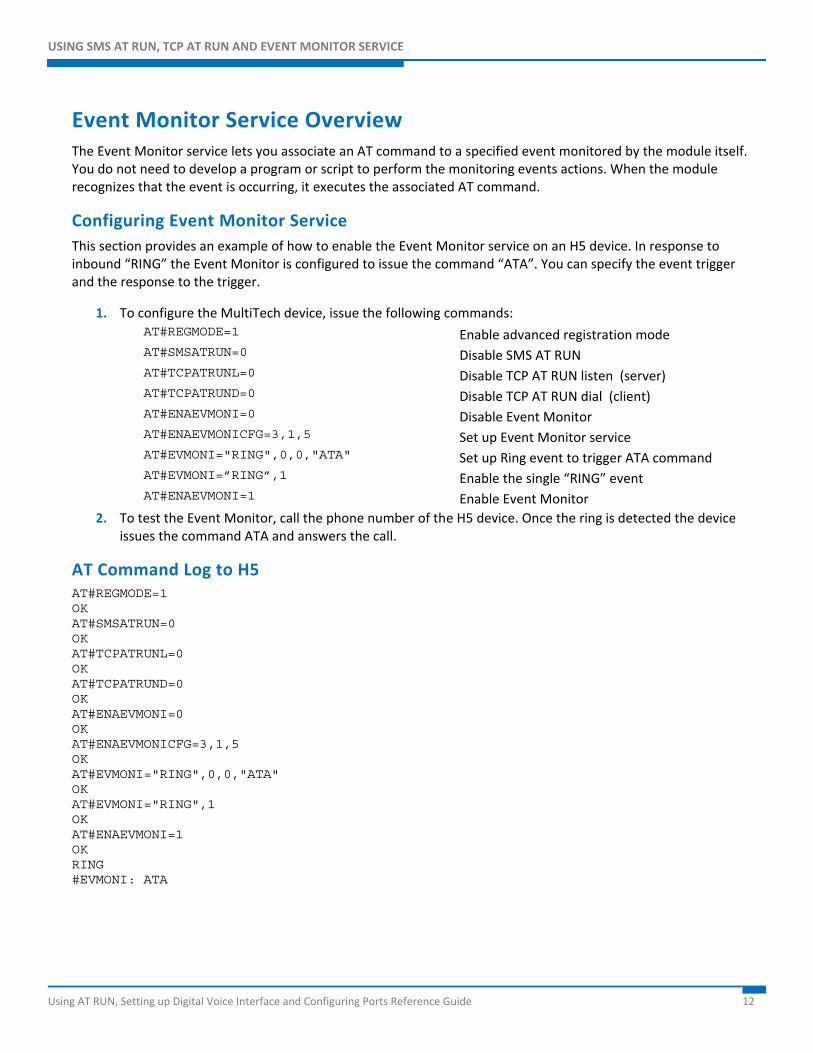
Event Monitor Service Overview The Event Monitor service lets you associate an AT command to a specified event monitored by the module itself. You do not need to develop a program or script to perform the monitoring events actions. When the module recognizes that the event is occurring, it executes the associated AT command.
Configuring Event Monitor Service This section provides an example of how to enable the Event Monitor service on an H5 device. In response to inbound “RING” the Event Monitor is configured to issue the command “ATA”. You can specify the event trigger and the response to the trigger.
1. To configure the MultiTech device, issue the following commands: AT#REGMODE=1 Enable advanced registration mode AT#SMSATRUN=0 Disable SMS AT RUN AT#TCPATRUNL=0 Disable TCP AT RUN listen (server) AT#TCPATRUND=0 Disable TCP AT RUN dial (client) AT#ENAEVMONI=0 Disable Event Monitor AT#ENAEVMONICFG=3,1,5 Set up Event Monitor service AT#EVMONI="RING",0,0,"ATA" Set up Ring event to trigger ATA command AT#EVMONI=”RING”,1 Enable the single “RING” event AT#ENAEVMONI=1 Enable Event Monitor
2. To test the Event Monitor, call the phone number of the H5 device. Once the ring is detected the device issues the command ATA and answers the call.
AT Command Log to H5 AT#REGMODE=1 OK AT#SMSATRUN=0 OK AT#TCPATRUNL=0 OK AT#TCPATRUND=0 OK AT#ENAEVMONI=0 OK AT#ENAEVMONICFG=3,1,5 OK AT#EVMONI="RING",0,0,"ATA" OK AT#EVMONI="RING",1 OK AT#ENAEVMONI=1 OK RING #EVMONI: ATA
USING THE DIGITAL VOICE INTERFACE
Using AT RUN, Setting up Digital Voice Interface and Configuring Ports Reference Guide 13
Using the Digital Voice Interface This section describes the Digital Voice Interface (DVI). It explains how to configure the interface and the audio formats of the DVI. This section provides examples and timing figures to help you better understand DVI. This section only applies to models that support voice.
The information is intended for users who need to develop applications dealing with signal voice in digital format.
This section describes the configurations of the Digital Voice Interface, for example, selecting the voice sampling frequency, the bit number of the voice sample, the audio formats, and so on. In addition, the configuration of a popular audio codec connected to the module is described. These activities are accomplished through I2S and I2C buses.
The following models support DIV:
MTPCIE-H5 MTPCIE-DK1
MTPCIE-EV3-N2 MTPCIE-EV3-N3 MTPCIE-EV3-N16
Overview of Where and How Digital Voice Interface is Used This section describes where and how you can use the Digital Voice Interface (DVI).
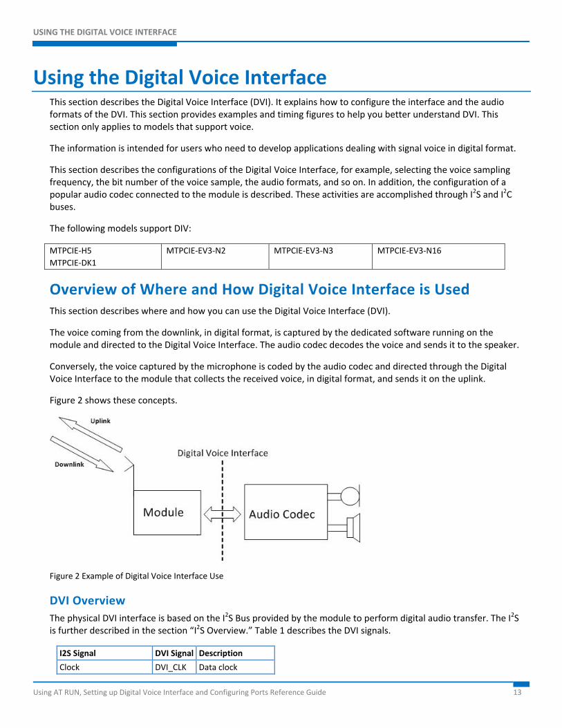
The voice coming from the downlink, in digital format, is captured by the dedicated software running on the module and directed to the Digital Voice Interface. The audio codec decodes the voice and sends it to the speaker.
Conversely, the voice captured by the microphone is coded by the audio codec and directed through the Digital Voice Interface to the module that collects the received voice, in digital format, and sends it on the uplink.
Figure 2 shows these concepts.
Figure 2 Example of Digital Voice Interface Use
DVI Overview The physical DVI interface is based on the I2S Bus provided by the module to perform digital audio transfer. The I2S is further described in the section “I2S Overview.” Table 1 describes the DVI signals.
I2S Signal DVI Signal Description
Clock DVI_CLK Data clock
USING THE DIGITAL VOICE INTERFACE
Using AT RUN, Setting up Digital Voice Interface and Configuring Ports Reference Guide 14
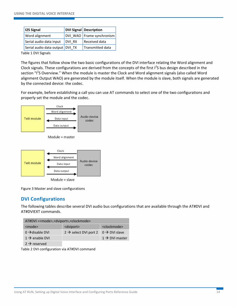
I2S Signal DVI Signal Description
Word alignment DVI_WAO Frame synchronism
Serial audio data input DVI_RX Received data
Serial audio data output DVI_TX Transmitted data Table 1 DVI Signals
The figures that follow show the two basic configurations of the DVI interface relating the Word alignment and Clock signals. These configurations are derived from the concepts of the first I2S bus design described in the section “I2S Overview.” When the module is master the Clock and Word alignment signals (also called Word alignment Output WAO) are generated by the module itself. When the module is slave, both signals are generated by the connected device: the codec.
For example, before establishing a call you can use AT commands to select one of the two configurations and properly set the module and the codec.
Figure 3 Master and slave configurations
DVI Configurations The following tables describe several DVI audio bus configurations that are available through the AT#DVI and AT#DVIEXT commands.
AT#DVI =<mode>,<dviport>,<clockmode>
<mode> <dviport> <clockmode>
0 disable DVI 2 select DVI port 2 0 DVI slave
1 enable DVI 1 DVI master
2 reserved Table 2 DVI configuration via AT#DVI command
USING THE DIGITAL VOICE INTERFACE
Using AT RUN, Setting up Digital Voice Interface and Configuring Ports Reference Guide 15
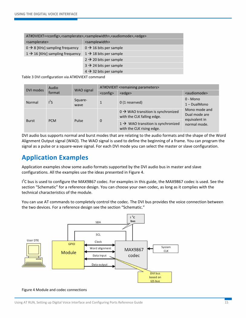
AT#DVIEXT=<config>,<samplerate>,<samplewidth>,<audiomode>,<edge>
<samplerate> <samplewidth>
0 8 [KHz] sampling frequency 0 16 bits per sample
1 16 [KHz] sampling frequency 1 18 bits per sample
2 20 bits per sample
3 24 bits per sample
4 32 bits per sample Table 3 DVI configuration via AT#DVIEXT command
DVI modes Audio format
WAO signal AT#DVIEXT <remaining parameters>
<config> <edge> <audiomode>
Normal I2S Square-wave
1 0 (1 reserved) 0 - Mono 1 – DualMono Mono mode and Dual mode are equivalent in normal mode.
Burst PCM Pulse 0
0 WAO transition is synchronized with the CLK falling edge.
1 WAO transition is synchronized with the CLK rising edge.
DVI audio bus supports normal and burst modes that are relating to the audio formats and the shape of the Word Alignment Output signal (WAO). The WAO signal is used to define the beginning of a frame. You can program the signal as a pulse or a square-wave signal. For each DVI mode you can select the master or slave configuration.
Application Examples Application examples show some audio formats supported by the DVI audio bus in master and slave configurations. All the examples use the ideas presented in Figure 4.
I2C bus is used to configure the MAX9867 codec. For examples in this guide, the MAX9867 codec is used. See the section “Schematic” for a reference design. You can choose your own codec, as long as it complies with the technical characteristics of the module.
You can use AT commands to completely control the codec. The DVI bus provides the voice connection between the two devices. For a reference design see the section “Schematic.”
Figure 4 Module and codec connections
USING THE DIGITAL VOICE INTERFACE
Using AT RUN, Setting up Digital Voice Interface and Configuring Ports Reference Guide 16
Normal Mode (I2S)
Module is Master
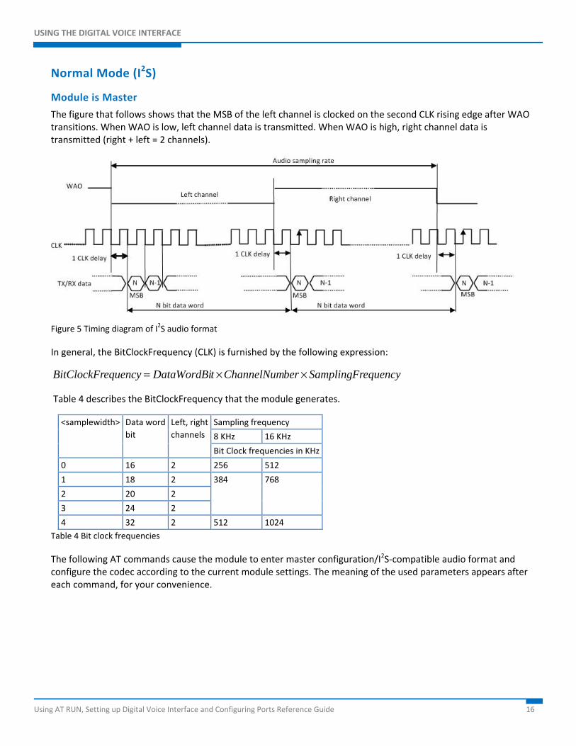
The figure that follows shows that the MSB of the left channel is clocked on the second CLK rising edge after WAO transitions. When WAO is low, left channel data is transmitted. When WAO is high, right channel data is transmitted (right + left = 2 channels).
Figure 5 Timing diagram of I2S audio format
In general, the BitClockFrequency (CLK) is furnished by the following expression:
equencySamplingFrberChannelNumtDataWordBiequencyBitClockFr ××=
Table 4 describes the BitClockFrequency that the module generates.
<samplewidth> Data word bit
Left, right channels
Sampling frequency
8 KHz 16 KHz
Bit Clock frequencies in KHz
0 16 2 256 512
1 18 2 384 768
2 20 2
3 24 2
4 32 2 512 1024 Table 4 Bit clock frequencies
The following AT commands cause the module to enter master configuration/I2S-compatible audio format and configure the codec according to the current module settings. The meaning of the used parameters appears after each command, for your convenience.
USING THE DIGITAL VOICE INTERFACE
Using AT RUN, Setting up Digital Voice Interface and Configuring Ports Reference Guide 17
Configuring the Module to operate with I2S-compatible audio format AT#DVI=1,2,1 OK
where:
1 Enable DVI
2 Use DVI port 2 (mandatory)
1 DVI master (factory setting)
AT#DVIEXT=1,0,0,1,0 OK
where:
1 Normal mode (factory setting)
0 Sample rate 8 KHz (factory setting)
0 16 bits per sample (factory setting)
1 Dual mono (factory setting)
0 I2S
Note: In the timing shown in Figure 5, the two N-bit data words are equals because the dual mono mode has been selected.
DVI bus
USING THE DIGITAL VOICE INTERFACE
Using AT RUN, Setting up Digital Voice Interface and Configuring Ports Reference Guide 18
Configuring the codec to operate with I2S audio format AT#I2CWR=x,y,30,4,19 >00109000100A330000330C0C09092424400060 OK
where:
x GPIO number used as SDA.
y GPIO number used as SCL.
30 Device address on I2C.
4 Register address from which start the writing.
19 number of bytes to write
>00109000
AT#I2CWR=x,y,30,17,1 >8A OK
where:
x GPIO number used as SDA
y GPIO number used as SCL
30 Device address on I2C
17 Register address where write data
1 Number of bytes to write
I2C bus
USING THE DIGITAL VOICE INTERFACE
Using AT RUN, Setting up Digital Voice Interface and Configuring Ports Reference Guide 19
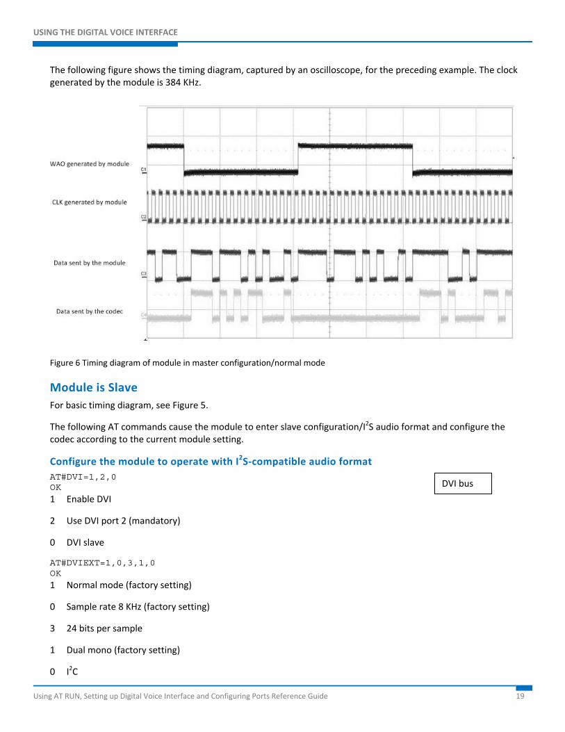
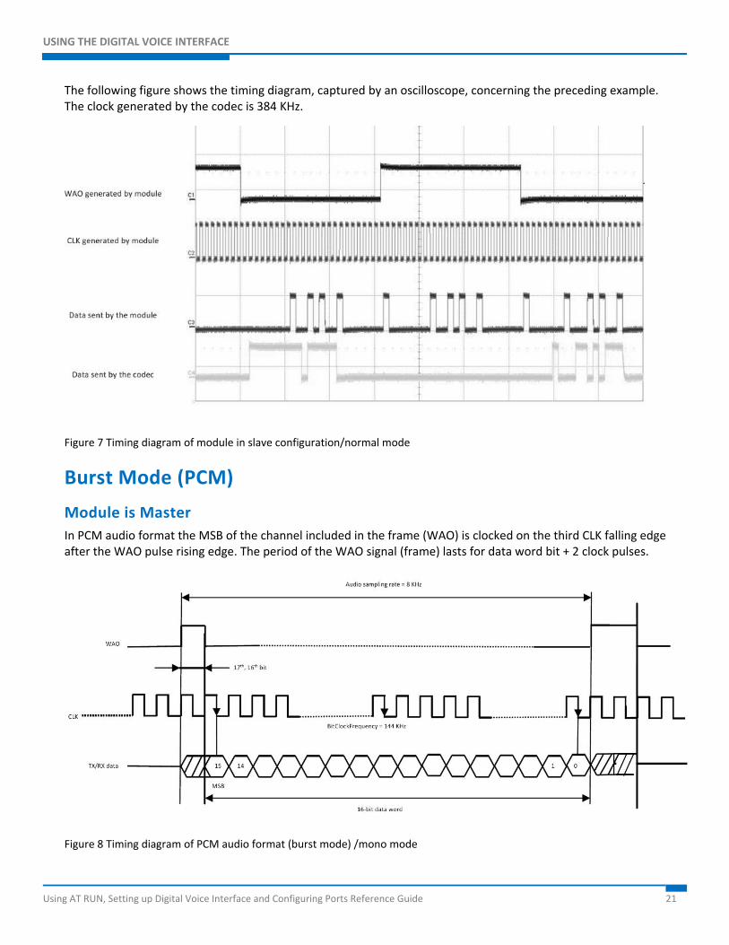
The following figure shows the timing diagram, captured by an oscilloscope, for the preceding example. The clock generated by the module is 384 KHz.
Figure 6 Timing diagram of module in master configuration/normal mode
Module is Slave For basic timing diagram, see Figure 5.
The following AT commands cause the module to enter slave configuration/I2S audio format and configure the codec according to the current module setting.
Configure the module to operate with I2S-compatible audio format AT#DVI=1,2,0 OK
1 Enable DVI
2 Use DVI port 2 (mandatory)
0 DVI slave
AT#DVIEXT=1,0,3,1,0 OK
1 Normal mode (factory setting)
0 Sample rate 8 KHz (factory setting)
3 24 bits per sample
1 Dual mono (factory setting)
0 I2C
DVI bus
USING THE DIGITAL VOICE INTERFACE
Using AT RUN, Setting up Digital Voice Interface and Configuring Ports Reference Guide 20
Note: The used codec, in master configuration, generates a clock equal to 384 KHz therefore the selected number of bits per sample on module is 24. For more information, see Table 4.
Configuring the codec to operate with I2S audio format AT#I2CWR=X,Y,30,4,19 >001010009002330000330C0C09092424400060 OK
x GPIO number used as SDA
y GPIO number used as SCL
30 Device address on I2C
4 Register address from which start the writing
19 Number of bytes to write
AT#I2CWR=x,y,30,17,1 >8A OK
x GPIO number used as SDA
y GPIO number used as SCL
30 Device address on I2C
17 Register address where write data
1 Number of bytes to write
I2C bus
USING THE DIGITAL VOICE INTERFACE
Using AT RUN, Setting up Digital Voice Interface and Configuring Ports Reference Guide 21
The following figure shows the timing diagram, captured by an oscilloscope, concerning the preceding example. The clock generated by the codec is 384 KHz.
Figure 7 Timing diagram of module in slave configuration/normal mode
Burst Mode (PCM)
Module is Master In PCM audio format the MSB of the channel included in the frame (WAO) is clocked on the third CLK falling edge after the WAO pulse rising edge. The period of the WAO signal (frame) lasts for data word bit + 2 clock pulses.
Figure 8 Timing diagram of PCM audio format (burst mode) /mono mode

USING THE DIGITAL VOICE INTERFACE
Using AT RUN, Setting up Digital Voice Interface and Configuring Ports Reference Guide 22
In general, the BitClockFrequency (CLK) is furnished by the following expression:
( ) equencySamplingFrtDataWordBiequencyBitClockFr ×+= 2
USING THE DIGITAL VOICE INTERFACE
Using AT RUN, Setting up Digital Voice Interface and Configuring Ports Reference Guide 23
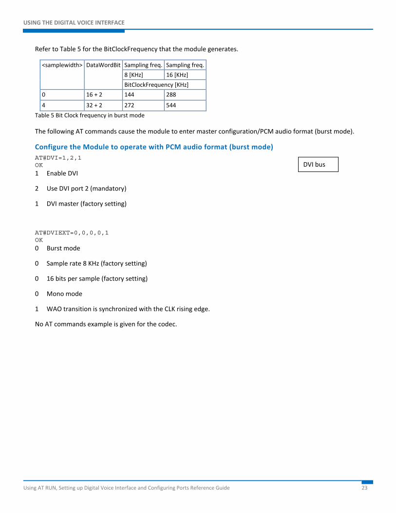
Refer to Table 5 for the BitClockFrequency that the module generates.
<samplewidth> DataWordBit Sampling freq. Sampling freq.
8 [KHz] 16 [KHz]
BitClockFrequency [KHz]
0 16 + 2 144 288
4 32 + 2 272 544
Table 5 Bit Clock frequency in burst mode
The following AT commands cause the module to enter master configuration/PCM audio format (burst mode).
Configure the Module to operate with PCM audio format (burst mode) AT#DVI=1,2,1 OK
1 Enable DVI
2 Use DVI port 2 (mandatory)
1 DVI master (factory setting)
AT#DVIEXT=0,0,0,0,1 OK
0 Burst mode
0 Sample rate 8 KHz (factory setting)
0 16 bits per sample (factory setting)
0 Mono mode
1 WAO transition is synchronized with the CLK rising edge.
No AT commands example is given for the codec.
DVI bus
USING THE DIGITAL VOICE INTERFACE
Using AT RUN, Setting up Digital Voice Interface and Configuring Ports Reference Guide 24
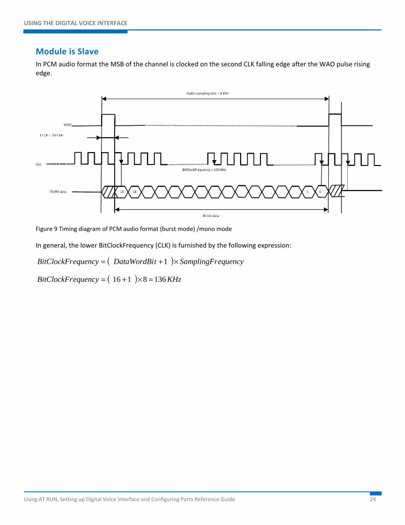
Module is Slave In PCM audio format the MSB of the channel is clocked on the second CLK falling edge after the WAO pulse rising edge.
Figure 9 Timing diagram of PCM audio format (burst mode) /mono mode
In general, the lower BitClockFrequency (CLK) is furnished by the following expression:
( ) equencySamplingFrtDataWordBiequencyBitClockFr ×+= 1
( ) KHzequencyBitClockFr 1368116 =×+=
USING THE DIGITAL VOICE INTERFACE
Using AT RUN, Setting up Digital Voice Interface and Configuring Ports Reference Guide 25
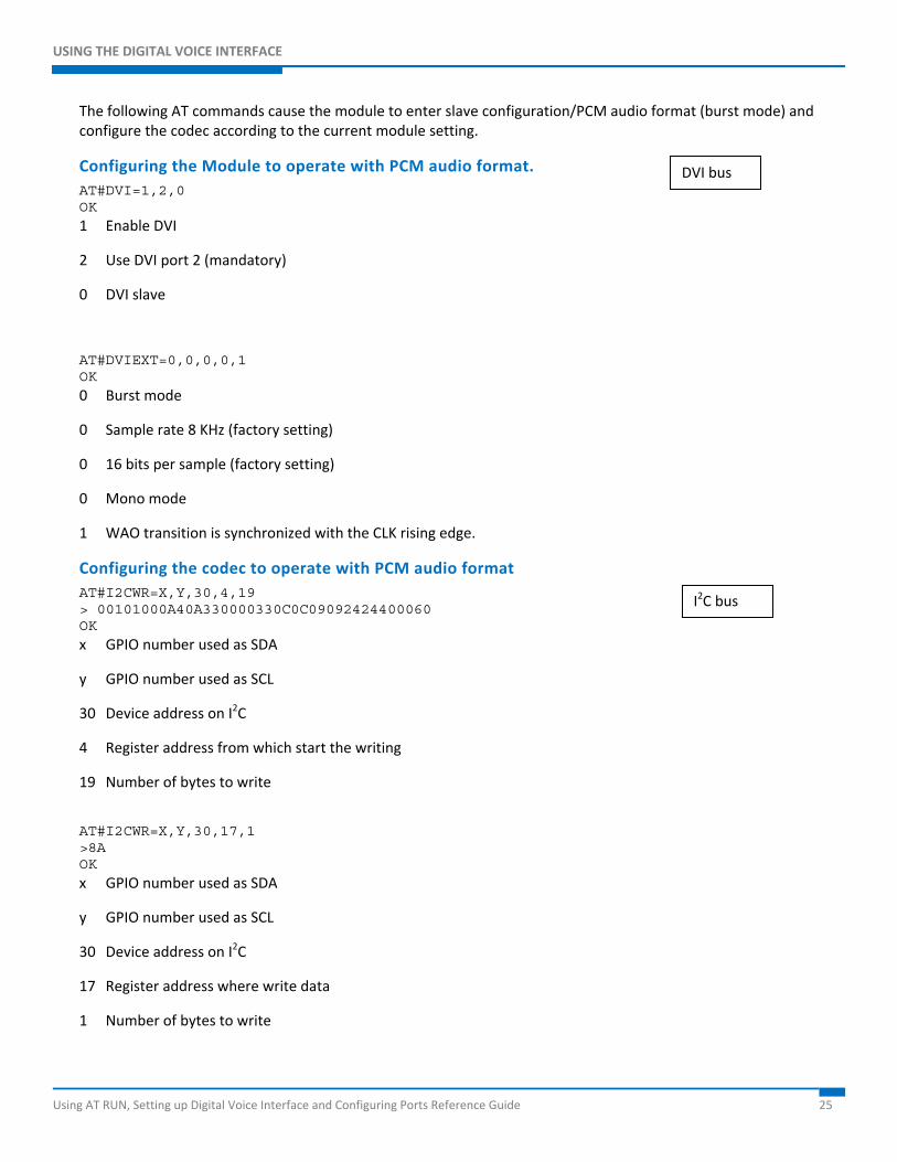
The following AT commands cause the module to enter slave configuration/PCM audio format (burst mode) and configure the codec according to the current module setting.
Configuring the Module to operate with PCM audio format. AT#DVI=1,2,0 OK 1 Enable DVI
2 Use DVI port 2 (mandatory)
0 DVI slave
AT#DVIEXT=0,0,0,0,1 OK
0 Burst mode
0 Sample rate 8 KHz (factory setting)
0 16 bits per sample (factory setting)
0 Mono mode
1 WAO transition is synchronized with the CLK rising edge.
Configuring the codec to operate with PCM audio format AT#I2CWR=X,Y,30,4,19 > 00101000A40A330000330C0C09092424400060 OK x GPIO number used as SDA
y GPIO number used as SCL
30 Device address on I2C
4 Register address from which start the writing
19 Number of bytes to write
AT#I2CWR=X,Y,30,17,1 >8A OK
x GPIO number used as SDA
y GPIO number used as SCL
30 Device address on I2C
17 Register address where write data
1 Number of bytes to write
I2C bus
DVI bus
USING THE DIGITAL VOICE INTERFACE
Using AT RUN, Setting up Digital Voice Interface and Configuring Ports Reference Guide 26
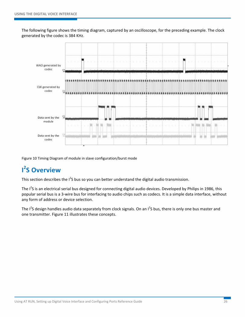
The following figure shows the timing diagram, captured by an oscilloscope, for the preceding example. The clock generated by the codec is 384 KHz.
Figure 10 Timing Diagram of module in slave configuration/burst mode
I2S Overview This section describes the I2S bus so you can better understand the digital audio transmission.
The I2S is an electrical serial bus designed for connecting digital audio devices. Developed by Philips in 1986, this popular serial bus is a 3-wire bus for interfacing to audio chips such as codecs. It is a simple data interface, without any form of address or device selection.
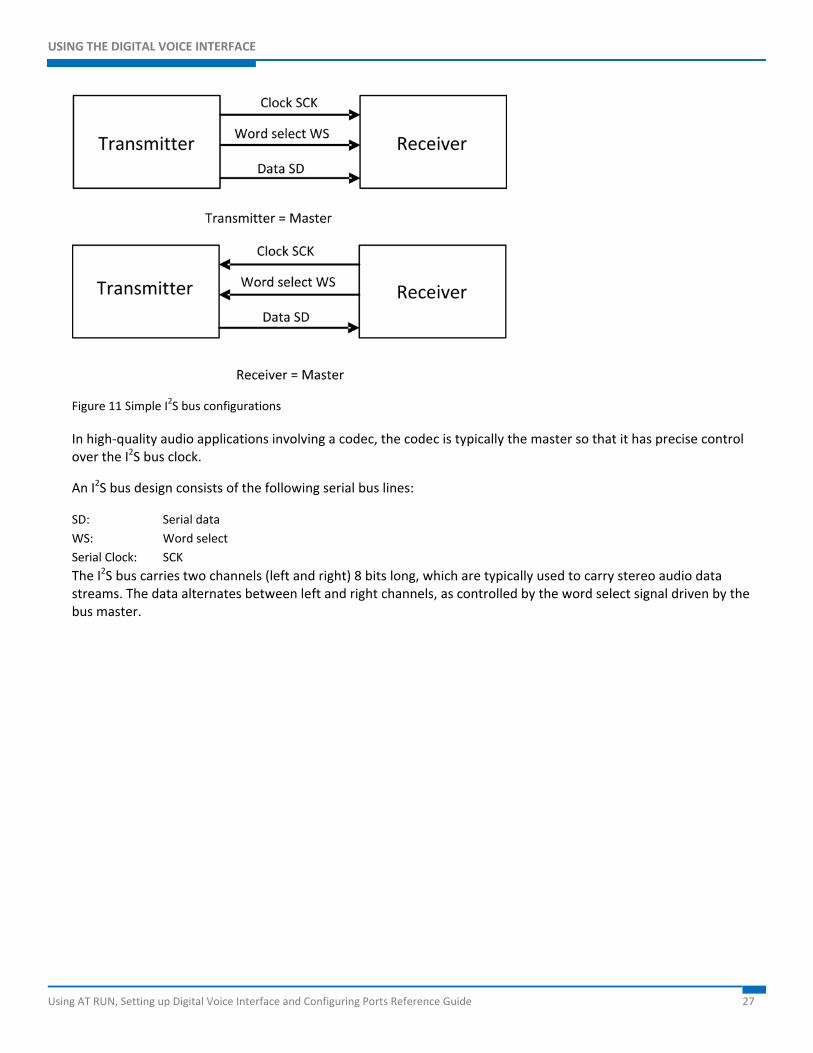
The I2S design handles audio data separately from clock signals. On an I2S bus, there is only one bus master and one transmitter. Figure 11 illustrates these concepts.
USING THE DIGITAL VOICE INTERFACE
Using AT RUN, Setting up Digital Voice Interface and Configuring Ports Reference Guide 27
Figure 11 Simple I2S bus configurations
In high-quality audio applications involving a codec, the codec is typically the master so that it has precise control over the I2S bus clock.
An I2S bus design consists of the following serial bus lines:
SD: Serial data WS: Word select Serial Clock: SCK The I2S bus carries two channels (left and right) 8 bits long, which are typically used to carry stereo audio data streams. The data alternates between left and right channels, as controlled by the word select signal driven by the bus master.
USING THE DIGITAL VOICE INTERFACE
Using AT RUN, Setting up Digital Voice Interface and Configuring Ports Reference Guide 28
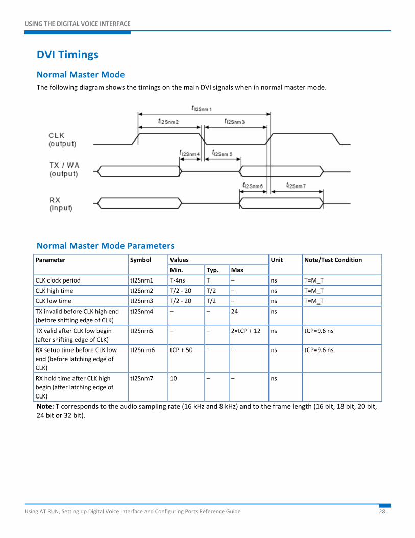
DVI Timings
Normal Master Mode The following diagram shows the timings on the main DVI signals when in normal master mode.
Normal Master Mode Parameters Parameter Symbol Values Unit Note/Test Condition
Min. Typ. Max
CLK clock period tI2Snm1 T-4ns T – ns T=M_T
CLK high time tI2Snm2 T/2 - 20 T/2 – ns T=M_T
CLK low time tI2Snm3 T/2 - 20 T/2 – ns T=M_T
TX invalid before CLK high end (before shifting edge of CLK)
tI2Snm4 – – 24 ns
TX valid after CLK low begin (after shifting edge of CLK)
tI2Snm5 – – 2×tCP + 12 ns tCP=9.6 ns
RX setup time before CLK low end (before latching edge of CLK)
tI2Sn m6 tCP + 50 – – ns tCP=9.6 ns
RX hold time after CLK high begin (after latching edge of CLK)
tI2Snm7 10 – – ns
Note: T corresponds to the audio sampling rate (16 kHz and 8 kHz) and to the frame length (16 bit, 18 bit, 20 bit, 24 bit or 32 bit).
USING THE DIGITAL VOICE INTERFACE
Using AT RUN, Setting up Digital Voice Interface and Configuring Ports Reference Guide 29
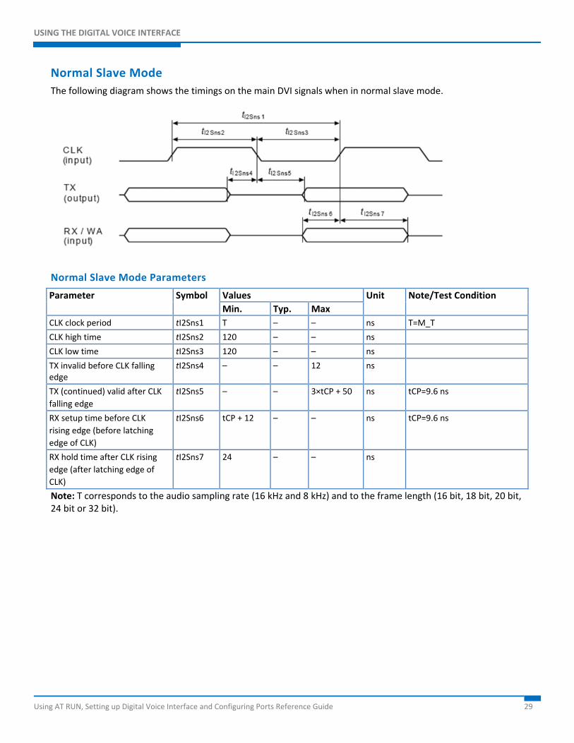
Normal Slave Mode The following diagram shows the timings on the main DVI signals when in normal slave mode.
Normal Slave Mode Parameters
Parameter Symbol Values Unit Note/Test Condition Min. Typ. Max
CLK clock period tI2Sns1 T – – ns T=M_T
CLK high time tI2Sns2 120 – – ns
CLK low time tI2Sns3 120 – – ns
TX invalid before CLK falling edge
tI2Sns4 – – 12 ns
TX (continued) valid after CLK falling edge
tI2Sns5 – – 3×tCP + 50 ns tCP=9.6 ns
RX setup time before CLK rising edge (before latching edge of CLK)
tI2Sns6 tCP + 12 – – ns tCP=9.6 ns
RX hold time after CLK rising edge (after latching edge of CLK)
tI2Sns7 24 – – ns
Note: T corresponds to the audio sampling rate (16 kHz and 8 kHz) and to the frame length (16 bit, 18 bit, 20 bit, 24 bit or 32 bit).
USING THE DIGITAL VOICE INTERFACE
Using AT RUN, Setting up Digital Voice Interface and Configuring Ports Reference Guide 30
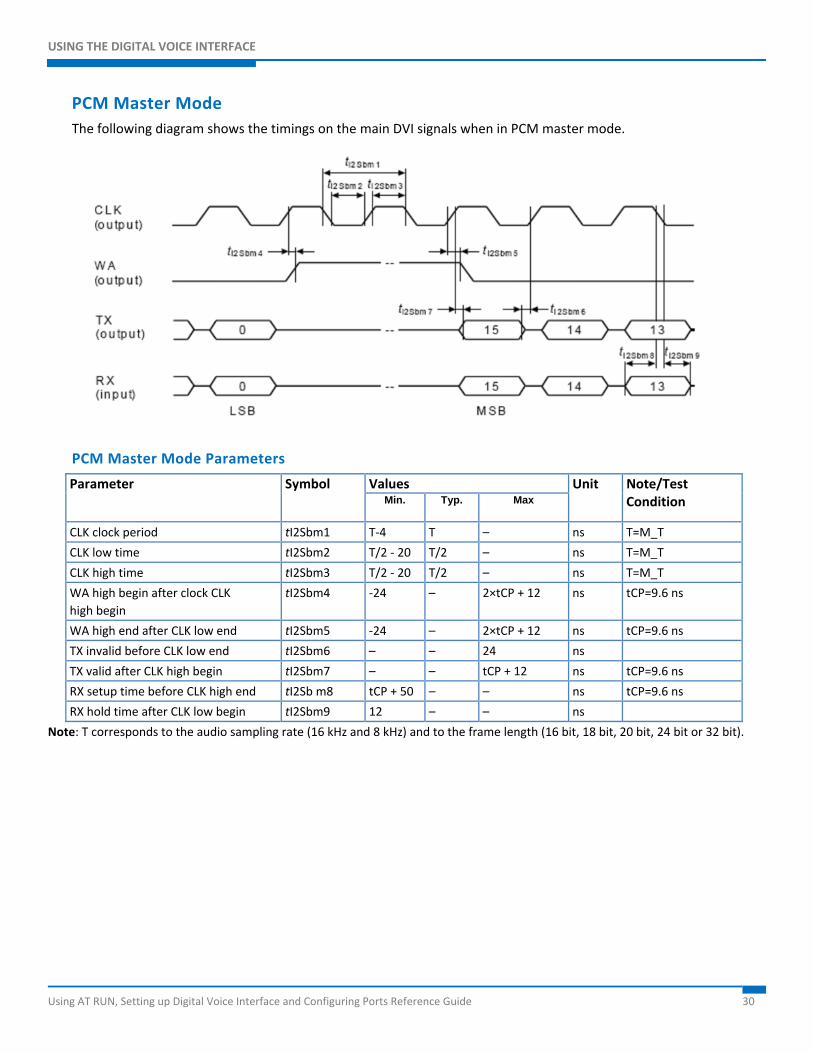
PCM Master Mode The following diagram shows the timings on the main DVI signals when in PCM master mode.
PCM Master Mode Parameters
Parameter Symbol Values Unit Note/Test Condition Min. Typ. Max
CLK clock period tI2Sbm1 T-4 T – ns T=M_T
CLK low time tI2Sbm2 T/2 - 20 T/2 – ns T=M_T
CLK high time tI2Sbm3 T/2 - 20 T/2 – ns T=M_T
WA high begin after clock CLK high begin
tI2Sbm4 -24 – 2×tCP + 12 ns tCP=9.6 ns
WA high end after CLK low end tI2Sbm5 -24 – 2×tCP + 12 ns tCP=9.6 ns
TX invalid before CLK low end tI2Sbm6 – – 24 ns
TX valid after CLK high begin tI2Sbm7 – – tCP + 12 ns tCP=9.6 ns
RX setup time before CLK high end tI2Sb m8 tCP + 50 – – ns tCP=9.6 ns
RX hold time after CLK low begin tI2Sbm9 12 – – ns
Note: T corresponds to the audio sampling rate (16 kHz and 8 kHz) and to the frame length (16 bit, 18 bit, 20 bit, 24 bit or 32 bit).
USING THE DIGITAL VOICE INTERFACE
Using AT RUN, Setting up Digital Voice Interface and Configuring Ports Reference Guide 31
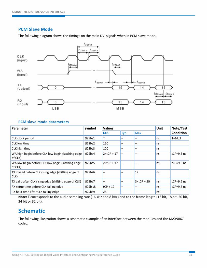
PCM Slave Mode The following diagram shows the timings on the main DVI signals when in PCM slave mode.
PCM slave mode parameters
Parameter symbol Values Unit Note/Test Condition Min. Typ. Max
CLK clock period tI2Sbs1 T – – ns T=M_T
CLK low time tI2Sbs2 120 – – ns
CLK high time tI2Sbs3 120 – – ns
WA high begin before CLK low begin (latching edge of CLK)
tI2Sbs4 2×tCP + 17 – – ns tCP=9.6 ns
WA low begin before CLK low begin (latching edge of CLK)
tI2Sbs5 2×tCP + 17 – – ns tCP=9.6 ns
TX invalid before CLK rising edge (shifting edge of CLK)
tI2Sbs6 – – 12 ns
TX valid after CLK rising edge (shifting edge of CLK) tI2Sbs7 – – 3×tCP + 50 ns tCP=9.6 ns
RX setup time before CLK falling edge tI2Sb s8 tCP + 12 – – ns tCP=9.6 ns
RX hold time after CLK falling edge tI2Sbs9 24 – – ns
Note: T corresponds to the audio sampling rate (16 kHz and 8 kHz) and to the frame length (16 bit, 18 bit, 20 bit, 24 bit or 32 bit).
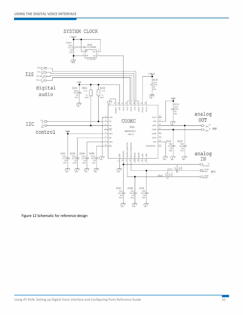
Schematic The following illustration shows a schematic example of an interface between the modules and the MAX9867 codec.
USING THE DIGITAL VOICE INTERFACE
Using AT RUN, Setting up Digital Voice Interface and Configuring Ports Reference Guide 32
Figure 12 Schematic for reference design
ARRANGING PORTS AND AVOIDING CONTENDED RESOURCES
Using AT RUN, Setting up Digital Voice Interface and Configuring Ports Reference Guide 33
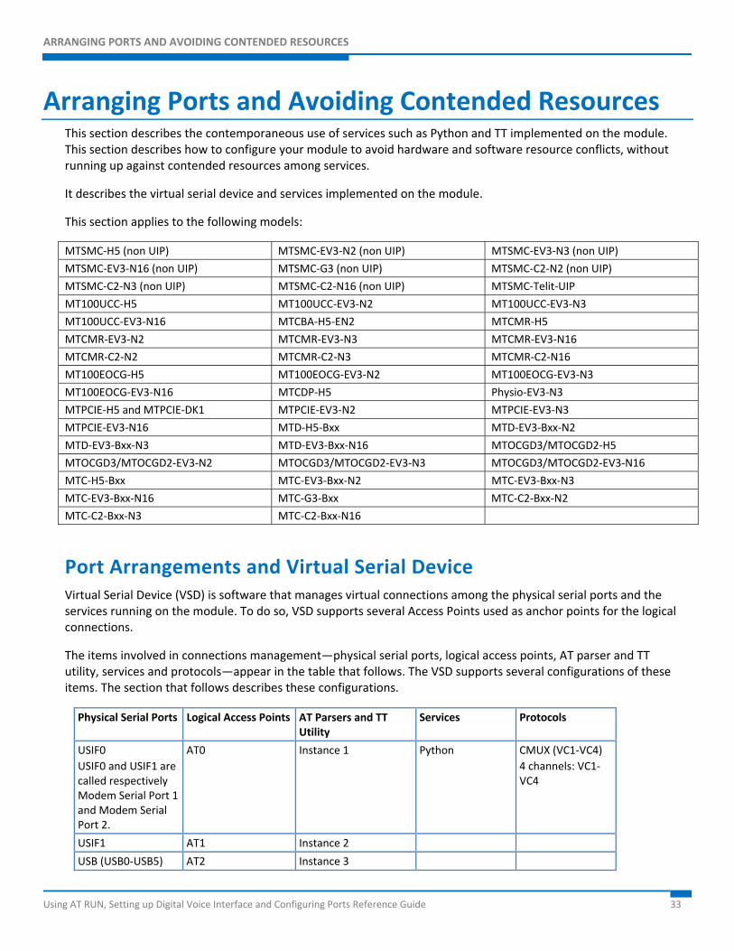
Arranging Ports and Avoiding Contended Resources This section describes the contemporaneous use of services such as Python and TT implemented on the module. This section describes how to configure your module to avoid hardware and software resource conflicts, without running up against contended resources among services.
It describes the virtual serial device and services implemented on the module.
This section applies to the following models:
MTSMC-H5 (non UIP) MTSMC-EV3-N2 (non UIP) MTSMC-EV3-N3 (non UIP)
MTSMC-EV3-N16 (non UIP) MTSMC-G3 (non UIP) MTSMC-C2-N2 (non UIP)
MTSMC-C2-N3 (non UIP) MTSMC-C2-N16 (non UIP) MTSMC-Telit-UIP
MT100UCC-H5 MT100UCC-EV3-N2 MT100UCC-EV3-N3
MT100UCC-EV3-N16 MTCBA-H5-EN2 MTCMR-H5
MTCMR-EV3-N2 MTCMR-EV3-N3 MTCMR-EV3-N16
MTCMR-C2-N2 MTCMR-C2-N3 MTCMR-C2-N16
MT100EOCG-H5 MT100EOCG-EV3-N2 MT100EOCG-EV3-N3
MT100EOCG-EV3-N16 MTCDP-H5 Physio-EV3-N3
MTPCIE-H5 and MTPCIE-DK1 MTPCIE-EV3-N2 MTPCIE-EV3-N3
MTPCIE-EV3-N16 MTD-H5-Bxx MTD-EV3-Bxx-N2
MTD-EV3-Bxx-N3 MTD-EV3-Bxx-N16 MTOCGD3/MTOCGD2-H5
MTOCGD3/MTOCGD2-EV3-N2 MTOCGD3/MTOCGD2-EV3-N3 MTOCGD3/MTOCGD2-EV3-N16
MTC-H5-Bxx MTC-EV3-Bxx-N2 MTC-EV3-Bxx-N3
MTC-EV3-Bxx-N16 MTC-G3-Bxx MTC-C2-Bxx-N2
MTC-C2-Bxx-N3 MTC-C2-Bxx-N16
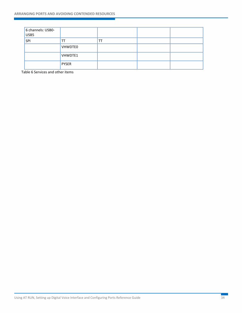
Port Arrangements and Virtual Serial Device Virtual Serial Device (VSD) is software that manages virtual connections among the physical serial ports and the services running on the module. To do so, VSD supports several Access Points used as anchor points for the logical connections.
The items involved in connections management—physical serial ports, logical access points, AT parser and TT utility, services and protocols—appear in the table that follows. The VSD supports several configurations of these items. The section that follows describes these configurations.
Physical Serial Ports Logical Access Points AT Parsers and TT Utility
Services Protocols
USIF0 USIF0 and USIF1 are called respectively Modem Serial Port 1 and Modem Serial Port 2.
AT0 Instance 1 Python CMUX (VC1-VC4) 4 channels: VC1-VC4
USIF1 AT1 Instance 2
USB (USB0-USB5) AT2 Instance 3
ARRANGING PORTS AND AVOIDING CONTENDED RESOURCES
Using AT RUN, Setting up Digital Voice Interface and Configuring Ports Reference Guide 34
6 channels: USB0-USB5
SPI TT TT
VHWDTE0
VHWDTE1
PYSER
Table 6 Services and other items
ARRANGING PORTS AND AVOIDING CONTENDED RESOURCES
Using AT RUN, Setting up Digital Voice Interface and Configuring Ports Reference Guide 35
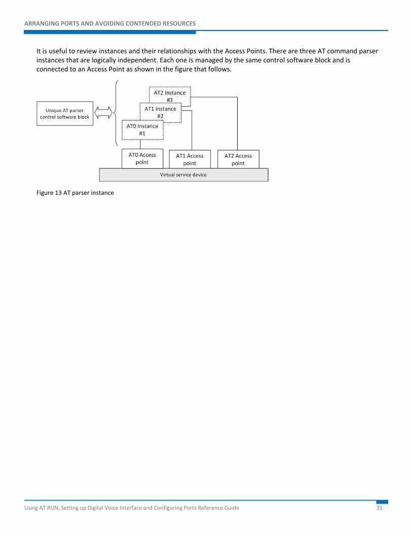
It is useful to review instances and their relationships with the Access Points. There are three AT command parser instances that are logically independent. Each one is managed by the same control software block and is connected to an Access Point as shown in the figure that follows.
Figure 13 AT parser instance
ARRANGING PORTS AND AVOIDING CONTENDED RESOURCES
Using AT RUN, Setting up Digital Voice Interface and Configuring Ports Reference Guide 36
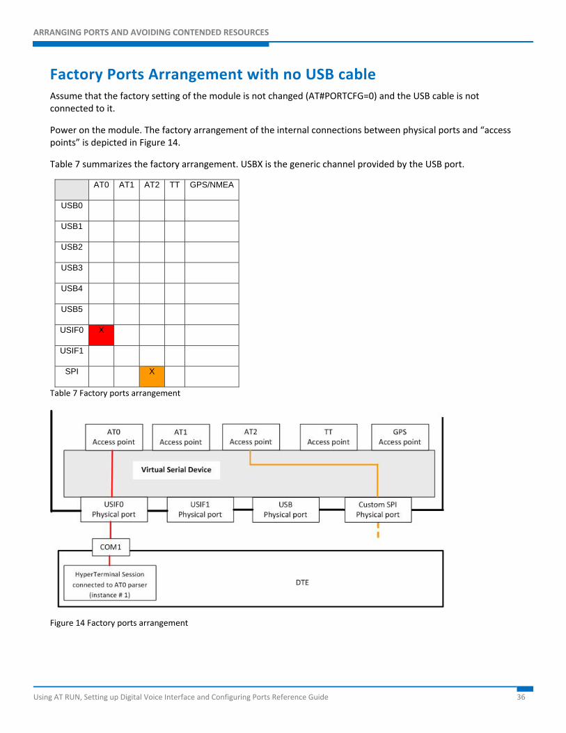
Factory Ports Arrangement with no USB cable Assume that the factory setting of the module is not changed (AT#PORTCFG=0) and the USB cable is not connected to it.
Power on the module. The factory arrangement of the internal connections between physical ports and “access points” is depicted in Figure 14.
Table 7 summarizes the factory arrangement. USBX is the generic channel provided by the USB port.
AT0 AT1 AT2 TT GPS/NMEA
USB0
USB1
USB2
USB3
USB4
USB5
USIF0 X
USIF1
SPI X
Table 7 Factory ports arrangement
Figure 14 Factory ports arrangement
ARRANGING PORTS AND AVOIDING CONTENDED RESOURCES
Using AT RUN, Setting up Digital Voice Interface and Configuring Ports Reference Guide 37
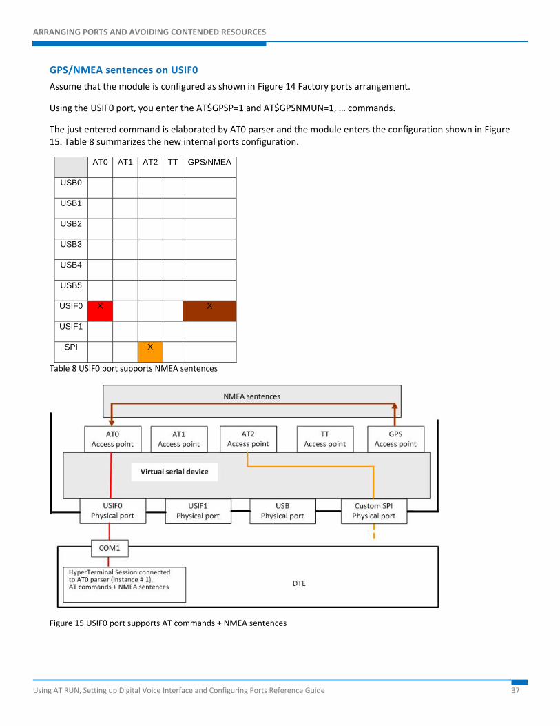
GPS/NMEA sentences on USIF0
Assume that the module is configured as shown in Figure 14 Factory ports arrangement.
Using the USIF0 port, you enter the AT$GPSP=1 and AT$GPSNMUN=1, … commands.
The just entered command is elaborated by AT0 parser and the module enters the configuration shown in Figure 15. Table 8 summarizes the new internal ports configuration.
AT0 AT1 AT2 TT GPS/NMEA
USB0
USB1
USB2
USB3
USB4
USB5
USIF0 X X
USIF1
SPI X
Table 8 USIF0 port supports NMEA sentences
Figure 15 USIF0 port supports AT commands + NMEA sentences
ARRANGING PORTS AND AVOIDING CONTENDED RESOURCES
Using AT RUN, Setting up Digital Voice Interface and Configuring Ports Reference Guide 38
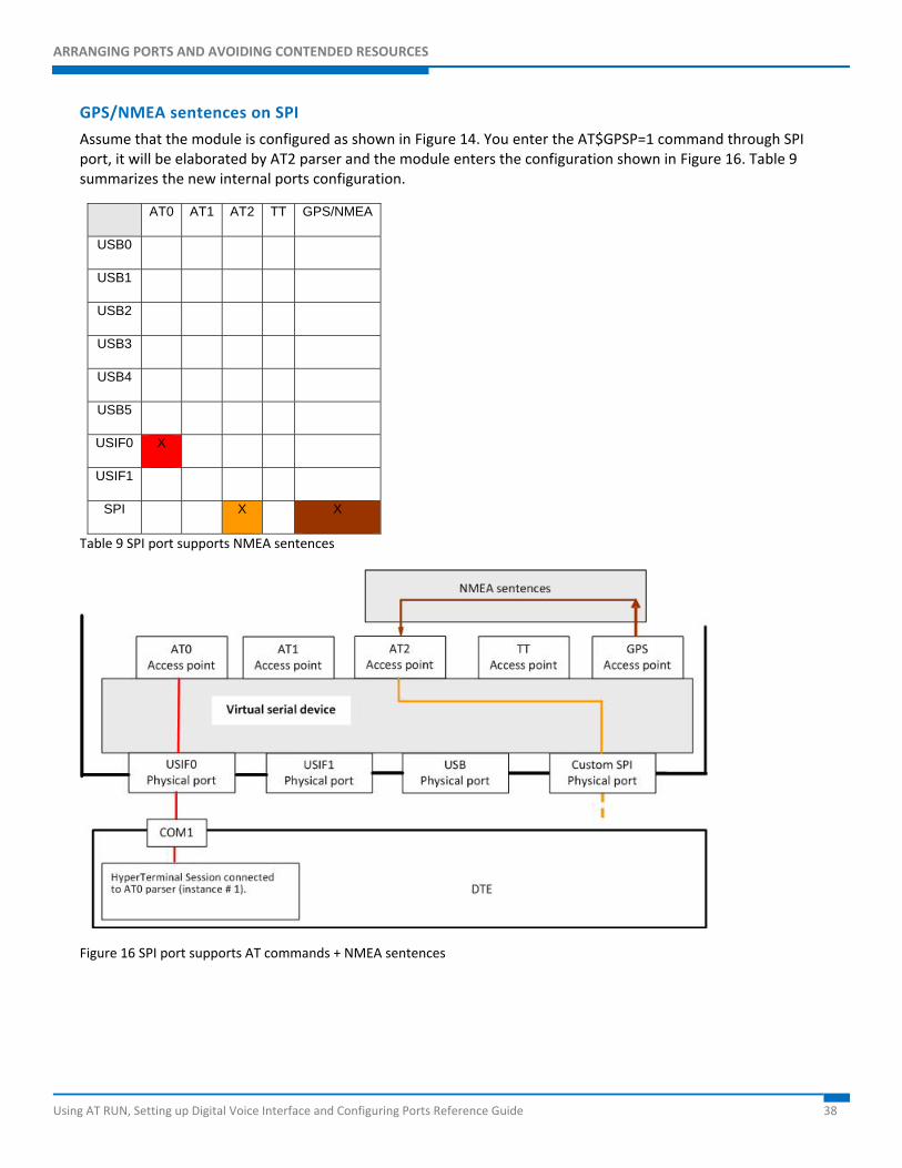
GPS/NMEA sentences on SPI
Assume that the module is configured as shown in Figure 14. You enter the AT$GPSP=1 command through SPI port, it will be elaborated by AT2 parser and the module enters the configuration shown in Figure 16. Table 9 summarizes the new internal ports configuration.
AT0 AT1 AT2 TT GPS/NMEA
USB0
USB1
USB2
USB3
USB4
USB5
USIF0 X
USIF1
SPI X X
Table 9 SPI port supports NMEA sentences
Figure 16 SPI port supports AT commands + NMEA sentences
ARRANGING PORTS AND AVOIDING CONTENDED RESOURCES
Using AT RUN, Setting up Digital Voice Interface and Configuring Ports Reference Guide 39
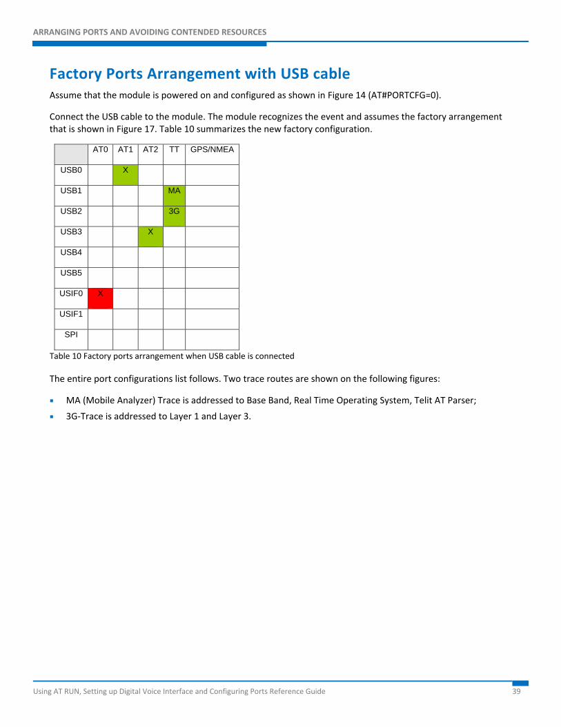
Factory Ports Arrangement with USB cable Assume that the module is powered on and configured as shown in Figure 14 (AT#PORTCFG=0).
Connect the USB cable to the module. The module recognizes the event and assumes the factory arrangement that is shown in Figure 17. Table 10 summarizes the new factory configuration.
AT0 AT1 AT2 TT GPS/NMEA
USB0 X
USB1 MA
USB2 3G
USB3 X
USB4
USB5
USIF0 X
USIF1
SPI
Table 10 Factory ports arrangement when USB cable is connected
The entire port configurations list follows. Two trace routes are shown on the following figures:
MA (Mobile Analyzer) Trace is addressed to Base Band, Real Time Operating System, Telit AT Parser;
3G-Trace is addressed to Layer 1 and Layer 3.
ARRANGING PORTS AND AVOIDING CONTENDED RESOURCES
Using AT RUN, Setting up Digital Voice Interface and Configuring Ports Reference Guide 40
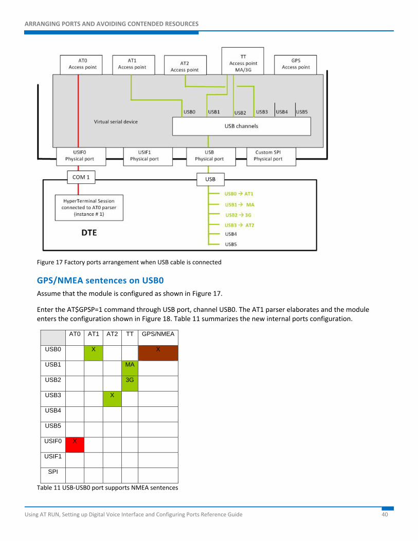
Figure 17 Factory ports arrangement when USB cable is connected
GPS/NMEA sentences on USB0 Assume that the module is configured as shown in Figure 17.
Enter the AT$GPSP=1 command through USB port, channel USB0. The AT1 parser elaborates and the module enters the configuration shown in Figure 18. Table 11 summarizes the new internal ports configuration.
AT0 AT1 AT2 TT GPS/NMEA
USB0 X X
USB1 MA
USB2 3G
USB3 X
USB4
USB5
USIF0 X
USIF1
SPI
Table 11 USB-USB0 port supports NMEA sentences
ARRANGING PORTS AND AVOIDING CONTENDED RESOURCES
Using AT RUN, Setting up Digital Voice Interface and Configuring Ports Reference Guide 41
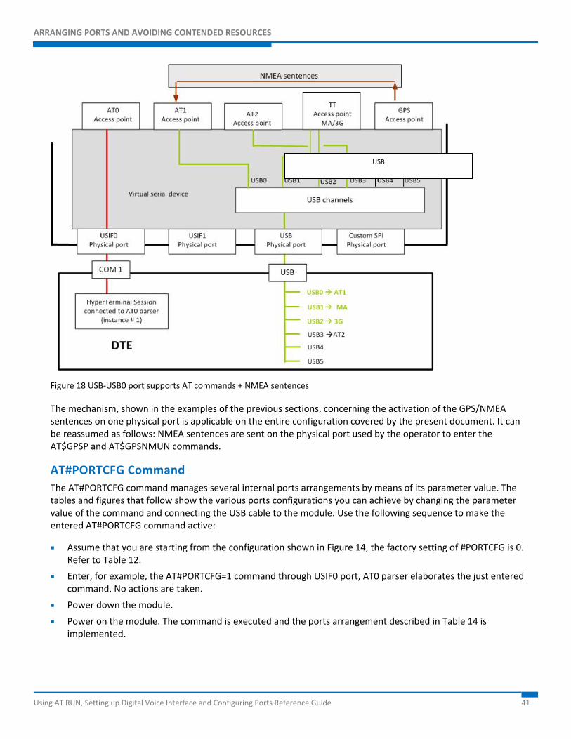
Figure 18 USB-USB0 port supports AT commands + NMEA sentences
The mechanism, shown in the examples of the previous sections, concerning the activation of the GPS/NMEA sentences on one physical port is applicable on the entire configuration covered by the present document. It can be reassumed as follows: NMEA sentences are sent on the physical port used by the operator to enter the AT$GPSP and AT$GPSNMUN commands.
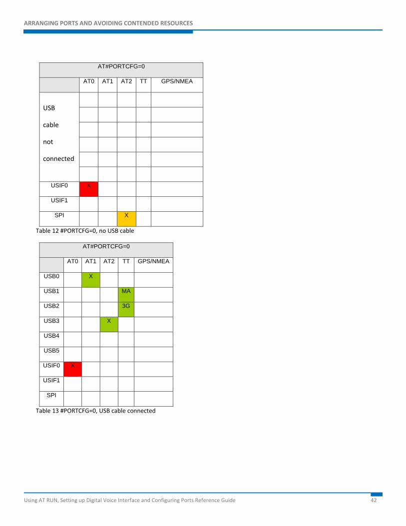
AT#PORTCFG Command The AT#PORTCFG command manages several internal ports arrangements by means of its parameter value. The tables and figures that follow show the various ports configurations you can achieve by changing the parameter value of the command and connecting the USB cable to the module. Use the following sequence to make the entered AT#PORTCFG command active:
Assume that you are starting from the configuration shown in Figure 14, the factory setting of #PORTCFG is 0. Refer to Table 12.
Enter, for example, the AT#PORTCFG=1 command through USIF0 port, AT0 parser elaborates the just entered command. No actions are taken.
Power down the module.
Power on the module. The command is executed and the ports arrangement described in Table 14 is implemented.
USB
ARRANGING PORTS AND AVOIDING CONTENDED RESOURCES
Using AT RUN, Setting up Digital Voice Interface and Configuring Ports Reference Guide 42
AT#PORTCFG=0
AT0 AT1 AT2 TT GPS/NMEA
USB
cable
not
connected
USIF0 X
USIF1
SPI X
Table 12 #PORTCFG=0, no USB cable
AT#PORTCFG=0
AT0 AT1 AT2 TT GPS/NMEA
USB0 X
USB1 MA
USB2 3G
USB3 X
USB4
USB5
USIF0 X
USIF1
SPI
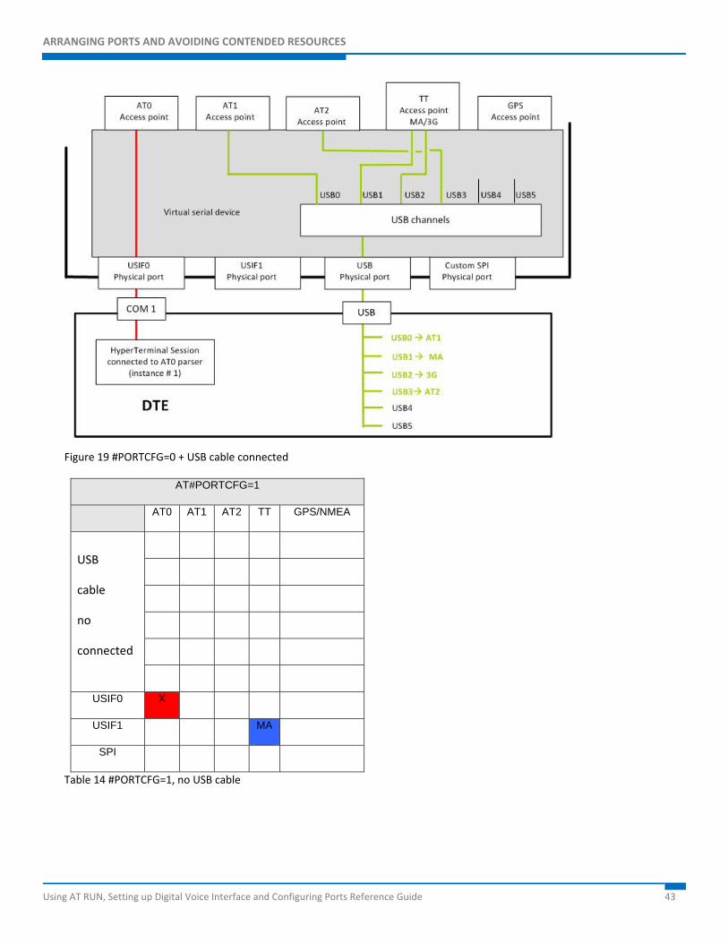
Table 13 #PORTCFG=0, USB cable connected
ARRANGING PORTS AND AVOIDING CONTENDED RESOURCES
Using AT RUN, Setting up Digital Voice Interface and Configuring Ports Reference Guide 43
Figure 19 #PORTCFG=0 + USB cable connected
AT#PORTCFG=1
AT0 AT1 AT2 TT GPS/NMEA
USB
cable
no
connected
USIF0 X
USIF1 MA
SPI
Table 14 #PORTCFG=1, no USB cable
ARRANGING PORTS AND AVOIDING CONTENDED RESOURCES
Using AT RUN, Setting up Digital Voice Interface and Configuring Ports Reference Guide 44
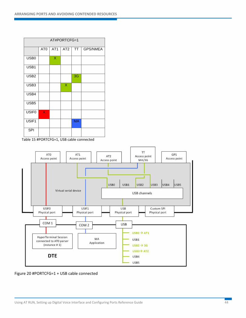
AT#PORTCFG=1
AT0 AT1 AT2 TT GPS/NMEA
USB0 X
USB1
USB2 3G
USB3 X
USB4
USB5
USIF0 X
USIF1 MA
SPI
Table 15 #PORTCFG=1, USB cable connected
Figure 20 #PORTCFG=1 + USB cable connected
ARRANGING PORTS AND AVOIDING CONTENDED RESOURCES
Using AT RUN, Setting up Digital Voice Interface and Configuring Ports Reference Guide 45
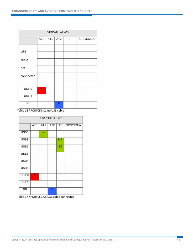
AT#PORTCFG=2
AT0 AT1 AT2 TT GPS/NMEA
USB
cable
not
connected
USIF0 X
USIF1
SPI X
Table 16 #PORTCFG=2, no USB cable
AT#PORTCFG=2
AT0 AT1 AT2 TT GPS/NMEA
USB0 X
USB1 MA
USB2 3G
USB3
USB4
USB5
USIF0 X
USIF1
SPI X
Table 17 #PORTCFG=2, USB cable connected
ARRANGING PORTS AND AVOIDING CONTENDED RESOURCES
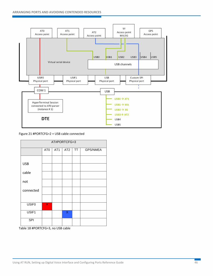
Using AT RUN, Setting up Digital Voice Interface and Configuring Ports Reference Guide 46
Figure 21 #PORTCFG=2 + USB cable connected
AT#PORTCFG=3
AT0 AT1 AT2 TT GPS/NMEA
USB
cable
not
connected
USIF0 X
USIF1 X
SPI
Table 18 #PORTCFG=3, no USB cable
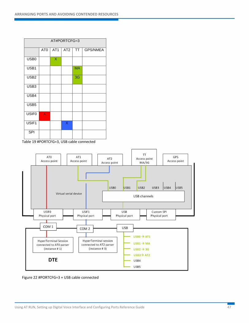
ARRANGING PORTS AND AVOIDING CONTENDED RESOURCES
Using AT RUN, Setting up Digital Voice Interface and Configuring Ports Reference Guide 47
AT#PORTCFG=3
AT0 AT1 AT2 TT GPS/NMEA
USB0 X
USB1 MA
USB2 3G
USB3
USB4
USB5
USIF0 X
USIF1 X
SPI
Table 19 #PORTCFG=3, USB cable connected
Figure 22 #PORTCFG=3 + USB cable connected
ARRANGING PORTS AND AVOIDING CONTENDED RESOURCES
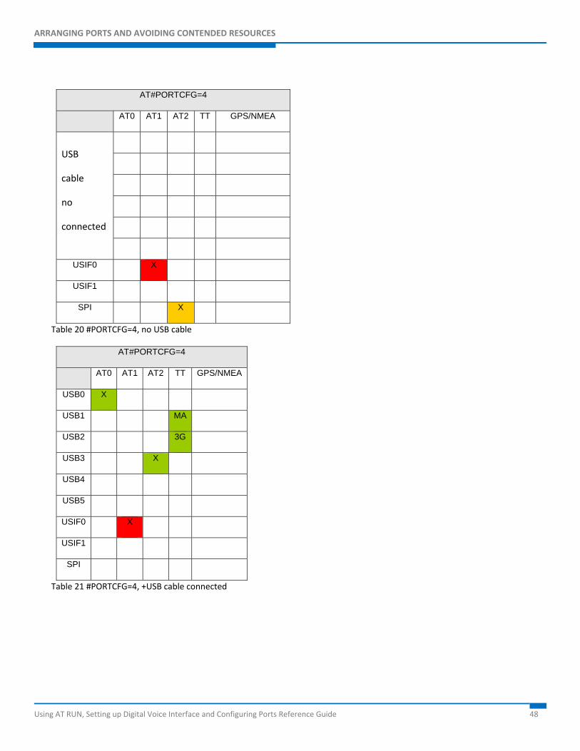
Using AT RUN, Setting up Digital Voice Interface and Configuring Ports Reference Guide 48
AT#PORTCFG=4
AT0 AT1 AT2 TT GPS/NMEA
USB
cable
no
connected
USIF0 X
USIF1
SPI X
Table 20 #PORTCFG=4, no USB cable
AT#PORTCFG=4
AT0 AT1 AT2 TT GPS/NMEA
USB0 X
USB1 MA
USB2 3G
USB3 X
USB4
USB5
USIF0 X
USIF1
SPI
Table 21 #PORTCFG=4, +USB cable connected
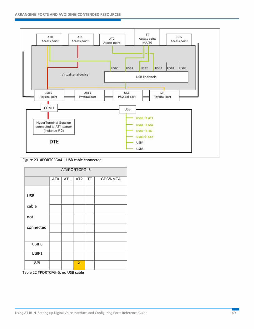
ARRANGING PORTS AND AVOIDING CONTENDED RESOURCES
Using AT RUN, Setting up Digital Voice Interface and Configuring Ports Reference Guide 49
Figure 23 #PORTCFG=4 + USB cable connected
AT#PORTCFG=5
AT0 AT1 AT2 TT GPS/NMEA
USB
cable
not
connected
USIF0
USIF1
SPI X
Table 22 #PORTCFG=5, no USB cable
ARRANGING PORTS AND AVOIDING CONTENDED RESOURCES
Using AT RUN, Setting up Digital Voice Interface and Configuring Ports Reference Guide 50
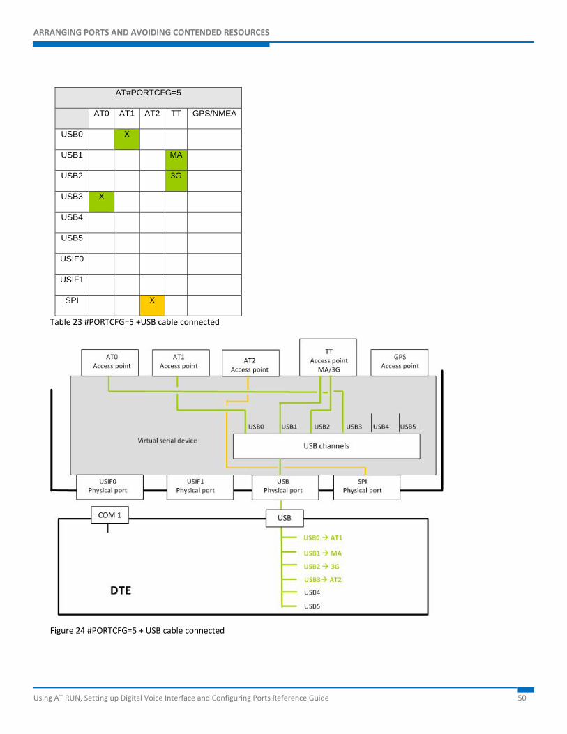
AT#PORTCFG=5
AT0 AT1 AT2 TT GPS/NMEA
USB0 X
USB1 MA
USB2 3G
USB3 X
USB4
USB5
USIF0
USIF1
SPI X
Table 23 #PORTCFG=5 +USB cable connected
Figure 24 #PORTCFG=5 + USB cable connected
ARRANGING PORTS AND AVOIDING CONTENDED RESOURCES
Using AT RUN, Setting up Digital Voice Interface and Configuring Ports Reference Guide 51
AT#PORTCFG=6
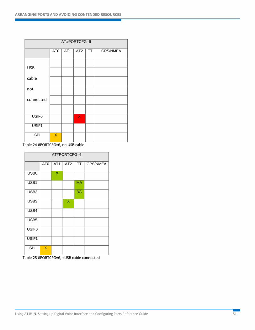
AT0 AT1 AT2 TT GPS/NMEA
USB
cable
not
connected
USIF0 X
USIF1
SPI X
Table 24 #PORTCFG=6, no USB cable
AT#PORTCFG=6
AT0 AT1 AT2 TT GPS/NMEA
USB0 X
USB1 MA
USB2 3G
USB3 X
USB4
USB5
USIF0
USIF1
SPI X
Table 25 #PORTCFG=6, +USB cable connected
ARRANGING PORTS AND AVOIDING CONTENDED RESOURCES
Using AT RUN, Setting up Digital Voice Interface and Configuring Ports Reference Guide 52
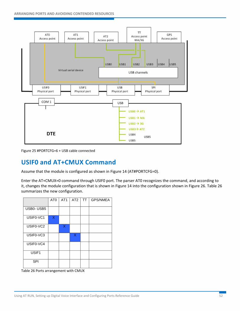
Figure 25 #PORTCFG=6 + USB cable connected
USIF0 and AT+CMUX Command Assume that the module is configured as shown in Figure 14 (AT#PORTCFG=0).
Enter the AT+CMUX=0 command through USIF0 port. The parser AT0 recognizes the command, and according to it, changes the module configuration that is shown in Figure 14 into the configuration shown in Figure 26. Table 26 summarizes the new configuration.
AT0 AT1 AT2 TT GPS/NMEA
USB0- USB5
USIF0-VC1 X
USIF0-VC2 X
USIF0-VC3 X
USIF0-VC4
USIF1
SPI
Table 26 Ports arrangement with CMUX
USB5
ARRANGING PORTS AND AVOIDING CONTENDED RESOURCES
Using AT RUN, Setting up Digital Voice Interface and Configuring Ports Reference Guide 53
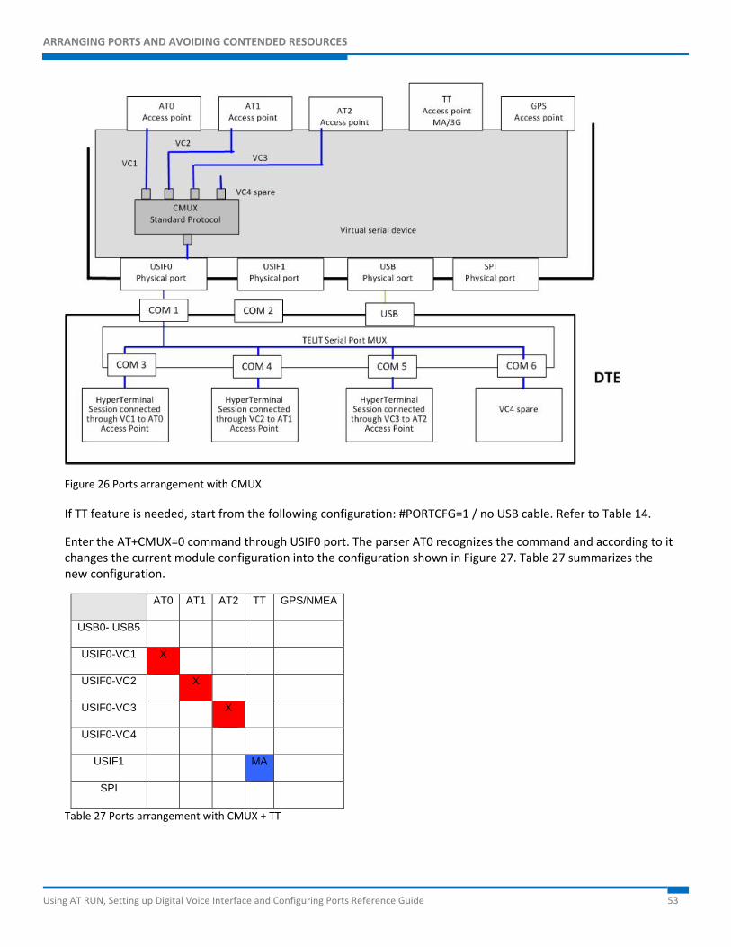
Figure 26 Ports arrangement with CMUX
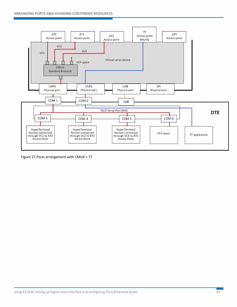
If TT feature is needed, start from the following configuration: #PORTCFG=1 / no USB cable. Refer to Table 14.
Enter the AT+CMUX=0 command through USIF0 port. The parser AT0 recognizes the command and according to it changes the current module configuration into the configuration shown in Figure 27. Table 27 summarizes the new configuration.
AT0 AT1 AT2 TT GPS/NMEA
USB0- USB5
USIF0-VC1 X
USIF0-VC2 X
USIF0-VC3 X
USIF0-VC4
USIF1 MA
SPI
Table 27 Ports arrangement with CMUX + TT
ARRANGING PORTS AND AVOIDING CONTENDED RESOURCES
Using AT RUN, Setting up Digital Voice Interface and Configuring Ports Reference Guide 54
Figure 27 Ports arrangement with CMUX + TT
ARRANGING PORTS AND AVOIDING CONTENDED RESOURCES
Using AT RUN, Setting up Digital Voice Interface and Configuring Ports Reference Guide 55
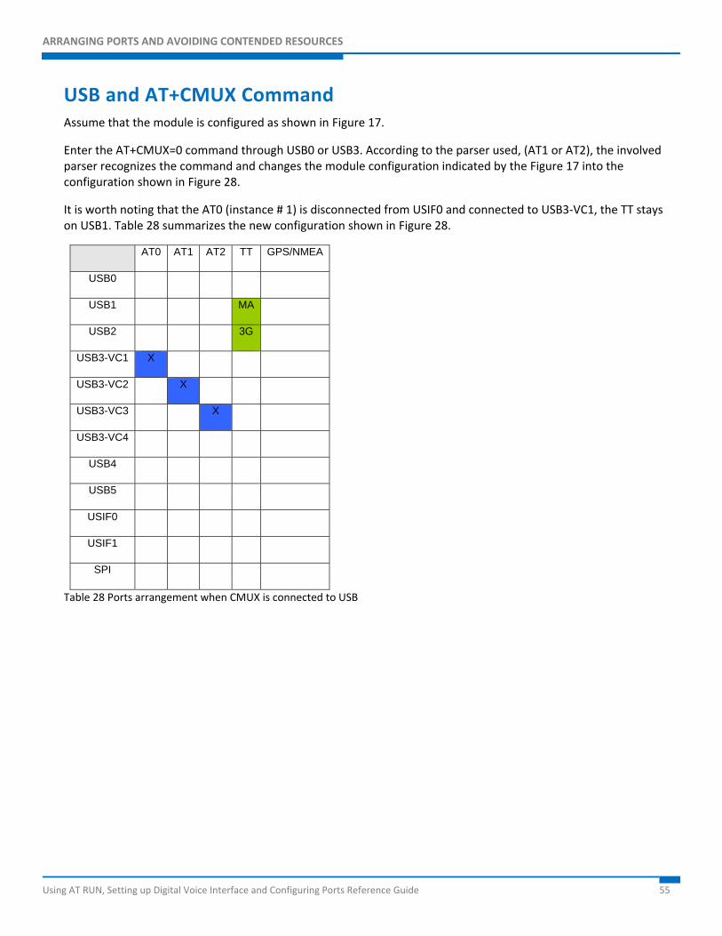
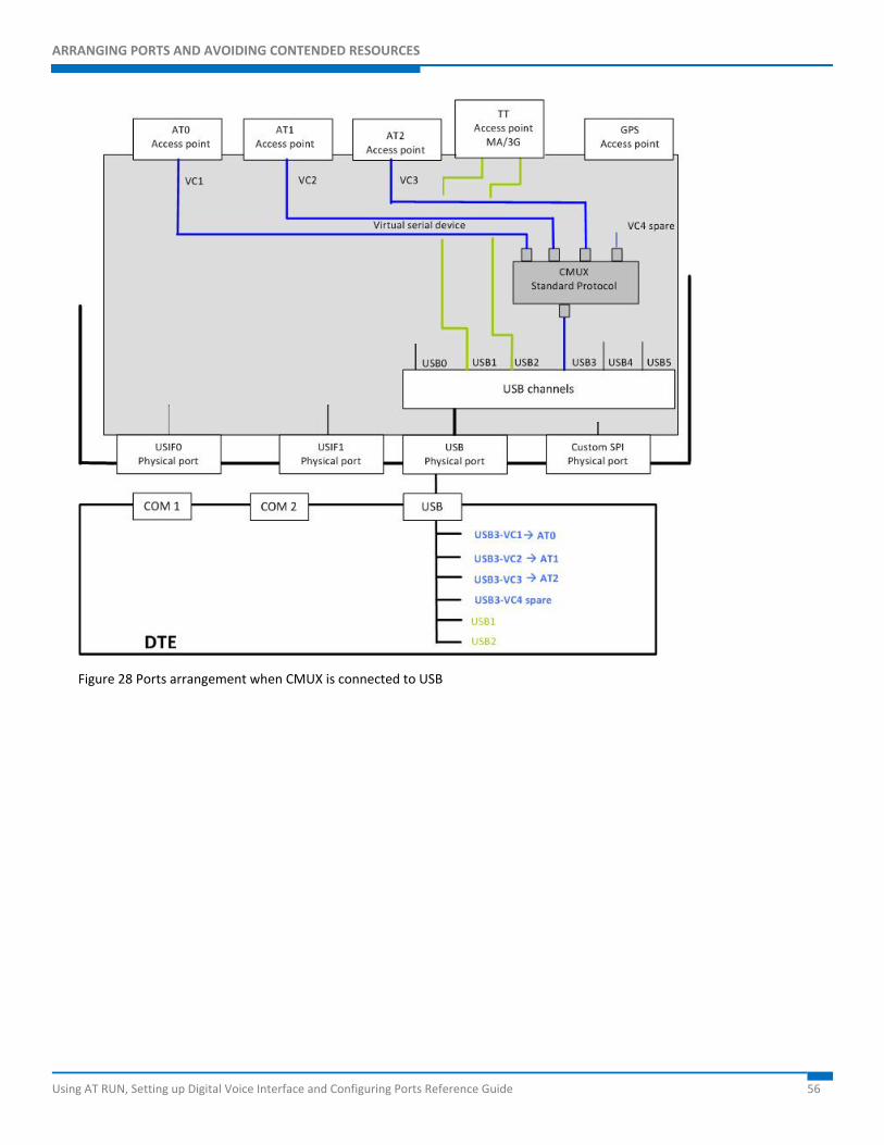
USB and AT+CMUX Command Assume that the module is configured as shown in Figure 17.
Enter the AT+CMUX=0 command through USB0 or USB3. According to the parser used, (AT1 or AT2), the involved parser recognizes the command and changes the module configuration indicated by the Figure 17 into the configuration shown in Figure 28.
It is worth noting that the AT0 (instance # 1) is disconnected from USIF0 and connected to USB3-VC1, the TT stays on USB1. Table 28 summarizes the new configuration shown in Figure 28.
AT0 AT1 AT2 TT GPS/NMEA
USB0
USB1 MA
USB2 3G
USB3-VC1 X
USB3-VC2 X
USB3-VC3 X
USB3-VC4
USB4
USB5
USIF0
USIF1
SPI
Table 28 Ports arrangement when CMUX is connected to USB
ARRANGING PORTS AND AVOIDING CONTENDED RESOURCES
Using AT RUN, Setting up Digital Voice Interface and Configuring Ports Reference Guide 56
Figure 28 Ports arrangement when CMUX is connected to USB
ARRANGING PORTS AND AVOIDING CONTENDED RESOURCES
Using AT RUN, Setting up Digital Voice Interface and Configuring Ports Reference Guide 57
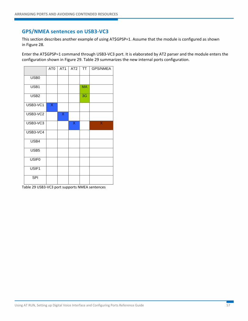
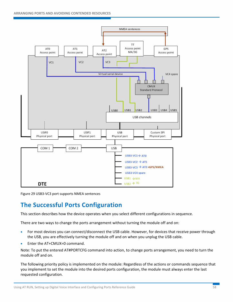
GPS/NMEA sentences on USB3-VC3 This section describes another example of using AT$GPSP=1. Assume that the module is configured as shown in Figure 28.
Enter the AT$GPSP=1 command through USB3-VC3 port. It is elaborated by AT2 parser and the module enters the configuration shown in Figure 29. Table 29 summarizes the new internal ports configuration.
AT0 AT1 AT2 TT GPS/NMEA
USB0
USB1 MA
USB2 3G
USB3-VC1 X
USB3-VC2 X
USB3-VC3 X X
USB3-VC4
USB4
USB5
USIF0
USIF1
SPI
Table 29 USB3-VC3 port supports NMEA sentences
ARRANGING PORTS AND AVOIDING CONTENDED RESOURCES
Using AT RUN, Setting up Digital Voice Interface and Configuring Ports Reference Guide 58
Figure 29 USB3-VC3 port supports NMEA sentences
The Successful Ports Configuration This section describes how the device operates when you select different configurations in sequence.
There are two ways to change the ports arrangement without turning the module off and on:
For most devices you can connect/disconnect the USB cable. However, for devices that receive power through the USB, you are effectively turning the module off and on when you unplug the USB cable.
Enter the AT+CMUX=0 command.
Note: To put the entered AT#PORTCFG command into action, to change ports arrangement, you need to turn the module off and on.
The following priority policy is implemented on the module: Regardless of the actions or commands sequence that you implement to set the module into the desired ports configuration, the module must always enter the last requested configuration.
ARRANGING PORTS AND AVOIDING CONTENDED RESOURCES
Using AT RUN, Setting up Digital Voice Interface and Configuring Ports Reference Guide 59
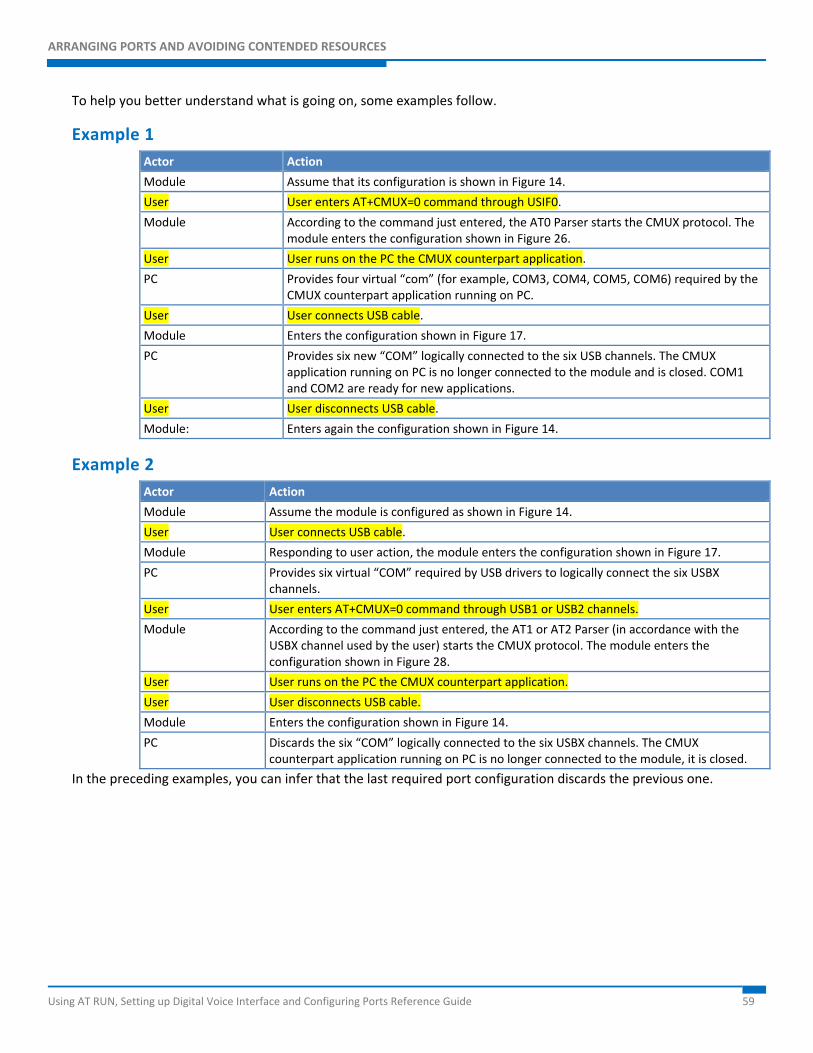
To help you better understand what is going on, some examples follow.
Example 1 Actor Action
Module Assume that its configuration is shown in Figure 14.
User User enters AT+CMUX=0 command through USIF0.
Module According to the command just entered, the AT0 Parser starts the CMUX protocol. The module enters the configuration shown in Figure 26.
User User runs on the PC the CMUX counterpart application.
PC Provides four virtual “com” (for example, COM3, COM4, COM5, COM6) required by the CMUX counterpart application running on PC.
User User connects USB cable.
Module Enters the configuration shown in Figure 17.
PC Provides six new “COM” logically connected to the six USB channels. The CMUX application running on PC is no longer connected to the module and is closed. COM1 and COM2 are ready for new applications.
User User disconnects USB cable.
Module: Enters again the configuration shown in Figure 14.
Example 2 Actor Action
Module Assume the module is configured as shown in Figure 14.
User User connects USB cable.
Module Responding to user action, the module enters the configuration shown in Figure 17.
PC Provides six virtual “COM” required by USB drivers to logically connect the six USBX channels.
User User enters AT+CMUX=0 command through USB1 or USB2 channels.
Module According to the command just entered, the AT1 or AT2 Parser (in accordance with the USBX channel used by the user) starts the CMUX protocol. The module enters the configuration shown in Figure 28.
User User runs on the PC the CMUX counterpart application.
User User disconnects USB cable.
Module Enters the configuration shown in Figure 14.
PC Discards the six “COM” logically connected to the six USBX channels. The CMUX counterpart application running on PC is no longer connected to the module, it is closed.
In the preceding examples, you can infer that the last required port configuration discards the previous one.
ARRANGING PORTS AND AVOIDING CONTENDED RESOURCES
Using AT RUN, Setting up Digital Voice Interface and Configuring Ports Reference Guide 60
Services
Python The modules provide the Python programming language. This gives you a tool to develop control scripts based on your communication and hardware resources. This section assumes that you are familiar with the Python language.
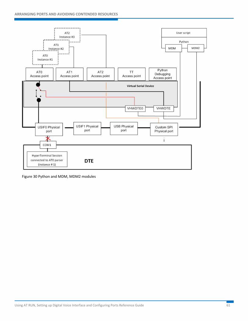
As shown in Figure 30 the VSD provides two access points called VHW DTE0 and VHW DTE1. MDM and MDM2 Python modules are logically connected respectively to VHW DTE0 and VHW DTE1 access points.
Assume that the module’s factory setting (AT#PORTCFG=0) is not changed and the USB cable is not connected. Next power on the module.
The factory arrangement of the internal connections between physical ports and “access points” is shown in Figure 14. Table 7 summarizes the factory arrangement.
When the Python script runs the Python instruction import MDM, the VSD disconnects the USIF0/AT0 logical connection and establishes the logical connection VHW DTE0/AT0. Consequently the Python script can access the AT0 parser.
In the same way, import MDM2 instruction forces the VSD to establish the logical connection VHW DTE1/AT1. As shown in Figure 30 it is possible to infer that USIF0 is disconnected and un-used from external module side.
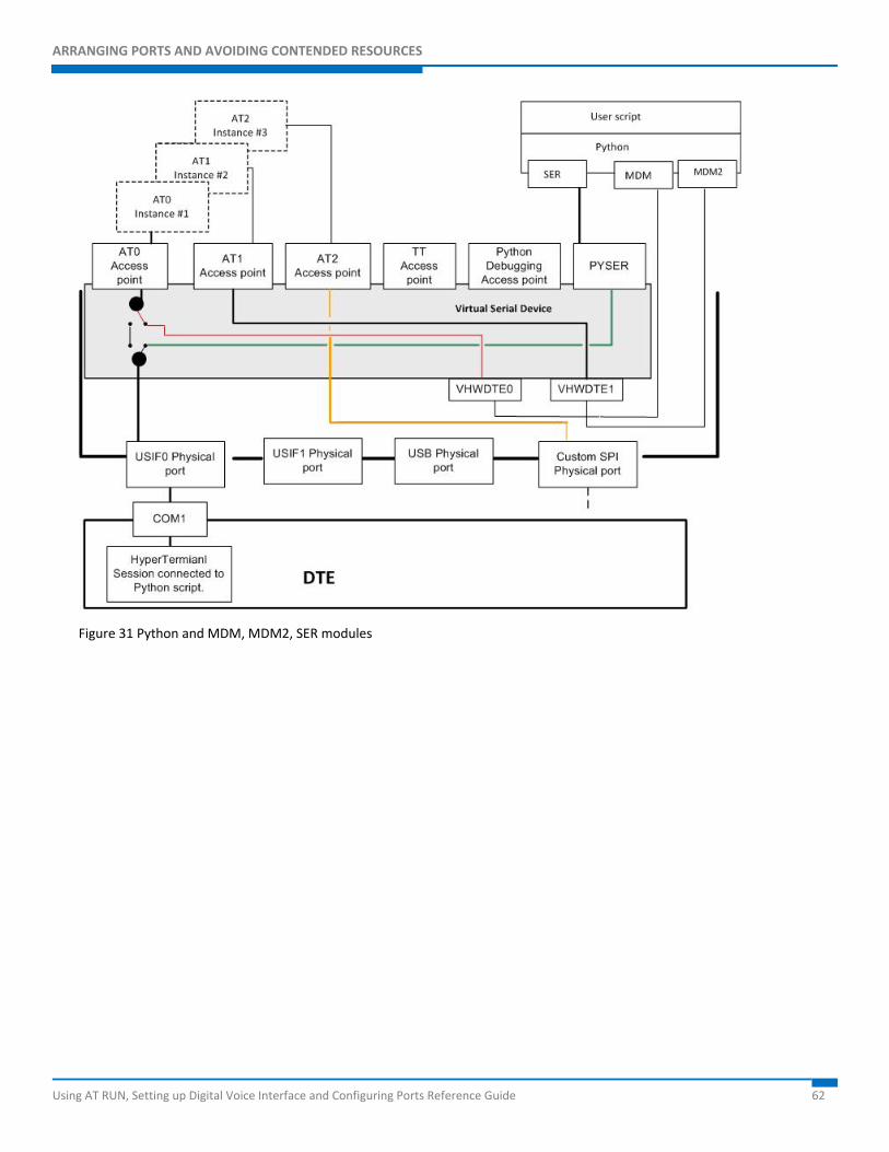
Python script can run another Python software module to use the USIF0 port using the instruction import SER. Figure 31 shows the new connection: through the physical port USIF0 it is possible to be connected with the Python script.
The three Python software modules (MDM, MDM2 and SER) make use of three independent resources: USIF0 physical port; AT0 and AT1 Access Point. No resources contention can arise among them. As a rule, the MDM, MDM2 and PRINT instructions take and use the resources regardless of the current owner.
ARRANGING PORTS AND AVOIDING CONTENDED RESOURCES
Using AT RUN, Setting up Digital Voice Interface and Configuring Ports Reference Guide 61
Figure 30 Python and MDM, MDM2 modules
ARRANGING PORTS AND AVOIDING CONTENDED RESOURCES
Using AT RUN, Setting up Digital Voice Interface and Configuring Ports Reference Guide 62
Figure 31 Python and MDM, MDM2, SER modules
ARRANGING PORTS AND AVOIDING CONTENDED RESOURCES
Using AT RUN, Setting up Digital Voice Interface and Configuring Ports Reference Guide 63
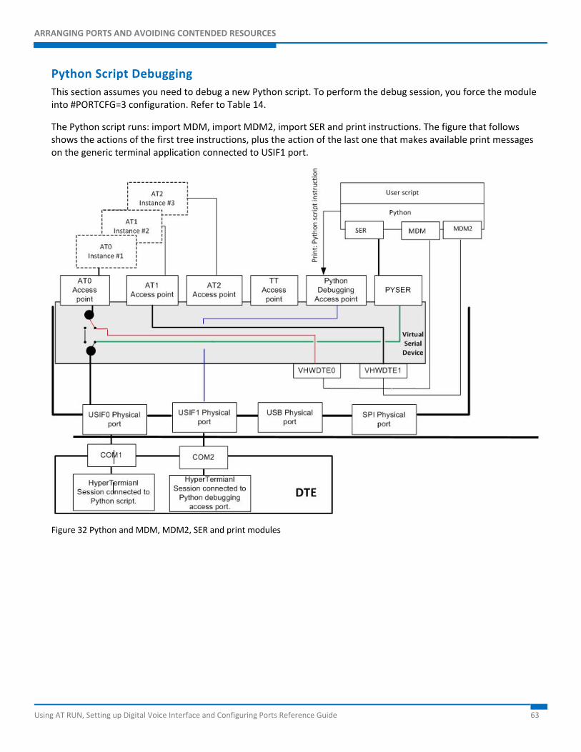
Python Script Debugging This section assumes you need to debug a new Python script. To perform the debug session, you force the module into #PORTCFG=3 configuration. Refer to Table 14.
The Python script runs: import MDM, import MDM2, import SER and print instructions. The figure that follows shows the actions of the first tree instructions, plus the action of the last one that makes available print messages on the generic terminal application connected to USIF1 port.
Figure 32 Python and MDM, MDM2, SER and print modules