Usha Capacitors Limited - Welcome to Usha Group of · PDF file · 2016-04-21Usha...
36
Excellence for more than Innovation and Two Decades www.ushapower.com +91 88260 18055 [email protected] Usha Capacitors Limited The Next Generation Engineering for Power Efficiency
Transcript of Usha Capacitors Limited - Welcome to Usha Group of · PDF file · 2016-04-21Usha...

Excellencefor more than
Innovation and
Two Decades
www.ushapower.com +91 88260 [email protected]
Usha Capacitors LimitedThe Next Generation Engineering for Power Efficiency

Welcome to the world of “Usha Power” make Industrial Capacitors for
Power Factor Improvement
PreludeWe at Usha Power want everyone to have scale. In addition, in power distribution with
access to Reliable, Efficient and Quality Low and Medium Voltage Networks, PFC
Energy, which is Sustainable. We are focuses on the Power Flow (CosФ) and the
committed to innovate ways and means to optimization of Voltage stability by address these needs and consequently, We generating reactive power – to improve as the Leader in Energy Saving Technology, voltage quality and reliability at distribution. provide the most relevant, state-of-the-art This will ensure not only enhancing Power technology solution of Power Factor Quality but also Improvement of Power Improvement through our wide range of Factor thus saving energy cost and fast Products. “Return On Investment” and Usha Power is
available at your back and call to provide The availability of Uninterruptable Quality you this service round the clock. Electrical Power and saving of Energy is the
need of the hour. Simultaneously,
awareness for the same is also increasing
globally.
To achieve these set goals, Power Factor
Correction Capacitors (PFC) and Harmonic
Filters are to be installed on an accelerating
www.ushapower.com
Usha PowerShunt Capacitor

02www.ushapower.com
Usha PowerShunt Capacitor
Incorporated as Usha Sales Corporation in 1992 UCL is a leading manufacturer of LV/HV Power
to undertake marketing of Electrical Capacitors Capacitors under the commercial brand name
in Eastern Part of India, based in Kolkata (then of “USHA POWER”. Our Broad portfolio
Calcutta). The company changed its includes Capacitors, Series reactors, APFC
constitution in the year of 2003 and formed as Relays, APFC Harmonic Filter, Thyristor
Usha Capacitors Pvt Ltd. Later, in the year 2004 Switched Harmonic Panel. As an innovative
Usha ventured into Electrical Turnkey Project technology- driven company, Usha focus
Execution Business with the name of, Usha technologically on demanding growth markets
Techno Power Pvt. Ltd. under the flagship of in the areas of Steel,
USHA GROUP. Power, Cement and
o t h e r H e a v y
Usha Group, the first generation business Industries. We offer
entrepreneur with over two decades of our partners both
experience in Electrical Capacitors and standard Capacitors
Electrical Turnkey Projects has achieved an as well as application-
exponential growth and success in the span of a specific solution.
very few years. With this success story behind,
USHA has designed, engineered, manufactured Usha became a coveted Usha Capacitors Ltd.
and marketed products in India and abroad. We in 2014.
are continuously strengthening our global
research and development network by The group has completed and successfully
expanding R & D activities at our Plant locations.delivered more than 120 Electrical Turnkey
Projects across India and abroad. To achieve
The Capacitor Division of Usha Group is such a feat, Usha Group has been backed by a
engaged in manufacturing of Capacitors team of over 125 competent professionals
according to national/ international standards. including highly qualified Engineers, MBAs etc.
“Usha Power” Make Capacitors are tested by Additional strength of Usha Group is its strong
CPRI (Bengaluru), ERDA (Vadodara), NTH infrastructure and high growth potential. Usha
(Kolkata). We are manufacturing products as per Capacitors Ltd (UCL) is an ISO:9001-2008 /
BIS/IEC standards and got ISI and CE 14001-2004 Certified Company.
certifications as well.
Introducing the CompanyProfile of a Leader
ISO:9001-200814001-2004Certified Company

The GroupComprises of the following 4 Companies
USHACAPACITORSLIMITED
UshaTechnoPowerPvt. Ltd.
Usha CapacitorsIndustrialCorporation
UshaElectricalLimited
Usha Capacitors Limitedinvolved in Designing, Engineering, Manufacturing of LV Shunt Capacitors, HV Capacitors, Surge Capacitors, Series Reactors (HV & LV), Furnace Duty Water Cooled Capacitors, Thyristor Switch, Vacuum Contactor.
Usha Techno Power Pvt. Ltd.engaged in Designing, Engineering, Manufacturing and Supplying of Electrical Panel Boards like, LDB, PDB, Control Desk, Bus Duct up to 33 kV, Drives Panel, VVFD Soft Starter Panel, AMF & Capacitor Control Panel, DG Synchronization Panel, PCC Panel, PLC Automation Drive Panel, Junction Box, Harmonic Analysis.
Meter Division, an Independent Strategic Business Unit, operates within the framework of this Company
Usha Electrical Limitedengaged in Electrical Turnkey Projects for High Rise Buildings, Hotels, Textiles Industries, Cement Industries, Power Generation Plants, Steel Industries, Chemical Industries, Mines, Agro-based Industries, Cold Storage, Bottling Plant and Utilities etc.
Usha Capacitors Industrial Corporation engaged in Electrical Consultancy, Energy Audit, Power Factor Management Service, AMC, etc.
03www.ushapower.com
Usha PowerShunt Capacitor
TM

Our Vision:
Our Mission:
Our Objectives:
To be the World-Leader in Capacitor, Reactor, Panel and Breaker Products.
To be the Doyen in Quality and Services for our Valued Customers.
To create Value for all our Stakeholders.
To supply Zero-defect Products and Services to the delight
of the Customers.
To attain all our defined Goals through a Highly Effective, Lean but strong and Fast-Pacing Organization.
To Provide Uninterrupted, Affordable Quality as well as Reliable Products and Services.
To become the most Customer Caring Company worldwide.
To be a Thousand Crore Company in less than 5 years time.
To be the Most Preferred Vendor (MPV) for all our Customers, however small or big.
To ensure growth through innovation by encouraging Ideas, Talent and Value system.
To spearhead excellence in all our Manufacturing/ Business Activities through sincerity and diligent effort of our Employees at all levels.
Our Vision,Mission & Our Values
04www.ushapower.com
Usha PowerShunt Capacitor
Guided byStrong Values

At Usha Group, our entire operation revolves around because our people are a treasured resource and that one objective which is: h a s w o r k e d
wonders with our Exceeding all Logical Expectations & Customers as Meeting Diverse Needs of our Customers and well as other Stakeholders. this focused approach influences every facet of the I hope our portal way we Develop, Manufacture and Install the extensive c r e a t e s a n range of products sought by our customers;opportunity for o u r v a l u e d to make our service impressive and memorable for visitors around our clients we, continuously innovate with practical the world to learn solutions that breathe new vitality into daily more about our interactions. l e a d i n g - e d g e operations, electrifying performances, strategies, There are exciting, yet challenging times at Usha Power services, sustainability, initiatives and values. This to which we ponder substantially and we continue to expression is part of the external manifestation of our set benchmarks in the field of innovation, technology commitment to servicing the Electrical Industry as; and engineering on real time basis. Usha has been Usha is One Stop Shop for all your Electrical needs. playing a major role in nation building since inception.
In the first place, by conducting Energy Audit in the I take this opportunity to express my gratitude and nook and corner of the country, bringing out clearly appreciation to all the stakeholders of Usha Power, drastic improvement needed in the Quality of Power who have always been demonstrating their solidarity in supply. We do these by improving the Power Factor of their association with us.the electricity supply at Consumers' end as well as
reducing the Transmission and Distribution losses on My sincere thanks to all our Global Associates, the Supply side. Financing Partners, Vendors, Customers, Departments In addition to this, we have also been handling our of Governments, Local Authorities, and most Corporate Social Responsibility (CSR) as one of our importantly, my dear Colleagues of Usha Power.prime responsibilities towards the society as a
business principle and as a matter of humility.
At Usha Power we strongly believe in “team-playing”
I feel privileged in penning this message as the CEO of Usha Group of Companies, an
organization whose seeds were sown in the early nineties. Over 2 decades, Usha has
grown significantly through a combination of technical excellence and strategic
acumen ship and today, we are one of the leading Industry-ready Electrical
Equipment Manufacturers in the country.
Whilst Capacitors and Panel remain at the heart of what we do, we have also
developed and expanded the range of services like Electrical Installation as well as
Design, Engineering and Turnkey Project Management along with Annual
Maintenance Contract and Energy Audit.
Focus on Being the BestCEO’s Message
M PandeyCEO
05www.ushapower.com
Usha PowerShunt Capacitor

Our employees are specialists in their fields. They bring a strong service ethos to everything they do. They take pride
and ownership in the jobs they do. At Usha, we bring passion, pride and experience together.
We pull together the right people, processes and expertise to take service from “good enough” to “great”. We apply
the best-in-class practices, domain knowledge and expertise, proven technologies, and innovation to assist our
clients in responding to new mandates and expanded missions. Usha's clients come back repeatedly with
confidence that we have the expertise to take service delivery to the next level of performance. We know how to
make services run smoother, smarter and more efficiently.
We have earned a reputation for collaborating with government and non-government agencies and have been
entrusted with delivering vital services for the Government, Leading Private and Public sector Organizations across
the world. The key to that success has been the trust of our customers. We have a history of designing and deploying
long-term solutions that has been generating meaningful outcomes since inception.
Our Employees
Our Structure
06www.ushapower.com
Usha PowerShunt Capacitor
FINANCECOLLABORATION& ACQUISITION LRP CRM
VP:WORKS
VP:NEW DELHI
CMDBOARD OFDIRECTORS
COO

One Stop SolutionWide Range of Products
Film
+ F
oil D
esig
nD
oubl
e La
yer
HV Series Reactor
Super Heavy Duty HEXL Type
Film
+ Fo
il Des
ign
Sing
le La
yer
Thrysitor Switch
Pole Mounted Bank
Gas fille
d U cap ca
pacitor
Cylin
dric
al H
eavy
Dut
y
Jel
ly F
illed
cap
acito
rs
HV Fixed Capacitor Bank
HV APFC System
Rectangular Square
Capacitors
Usha PowerShunt Capacitor
Hea
vy D
uty
Dou
ble
Die
lect
ric (M
KP) T
ype
Water Cooled Capacitors
LV Series Reactor
Heavy D
uty HEXL Type
Three Phase- 3 CT
Three Phase Single CT
Single Phase Single CTHT APFC Relay
Mix
ed D
iele
ctric
Cap
acito
rs
HV Indoor Fixed Bank
UR SE HW AO PP OA WH ES RU R UE S
HW AO P P OA WHS EU R RE USW HO AP
07www.ushapower.com
Usha PowerShunt Capacitor
HT Power Factor C
ontroller
APFC Relay

ProductsLow Voltage CapacitorsMPP Standard Design CapacitorsMKP Gas Filled Heavy Duty TypeHeavy Duty Hexl Jelly Filled TypeSuper Heavy Duty Hexl Type [Oil Filled/Jelly Filled/Gas Filled]App Capacitors [BOPP Film +Foil Design] OilFilled Single/Double Layer TypeMixed Dielectric Capcitors
FILM + FOIL DESIGN from 2.2 kV to 24 kV in single unit
Automatic Pad Mounted MV Capacitors Bank upto 11 kV
Medium Voltage Capacitors
6% / 7% / 14% Tuned and Detuned Reactors
MV Current Limiting Reactors of 0.2%
MV Harmonic Filter Reactors Alumunium
Wound Dry Air Core Type of 6%
LV/MV Series Reactors Copper wound /Aluminum Wound
Micro Processer Based APFC RelaysFrom 4 Step to 6, 8, 10, 12, 14, 16 Stage
HT APFC Relay
Water Cooled CapacitorsMV High Frequency Upto 1000 Hz
08www.ushapower.com
Usha PowerShunt Capacitor
High Voltage CapacitorsSVC Upto 700 kV

How Reactive Power is Generated?
Reducing Power Factor Cost
Factor approaches 1 the reactive (nonworking) Power
approaches 0.Every Electric Load that works with magnetic fields
(motors, chokes, transformers, inductive heating, arc
welding, and generators) produces a varying degree of
electrical lag, which is called inductance. This lag of
inductive loads maintains the current senses (e.g.
positive) for a time even though the negative-going
voltage tries to reserve it. This phase shift between
current and voltage is maintained, current and voltage
having opposite signs. During this time, negative Power
or Energy is produced and fed back into the network.
When current and voltage have the same sign again, the
same amount of energy is again needed to build up the To understand Power Factor, visualize a horse pulling a magnetic fields in inductive loads. This magnetic reversal railroad car down a rail road track. Because the rail road energy is called Reactive Power. track are uneven, the horse must pull the car from the In AC networks (50/60 Hz) such a process is repeated 50 side of the track. The horse is pulling the rail road car at or 60 times a second. So an obvious solution is to briefly an angle to the direction of the car's travel. The Power store the magnetic reversal energy in Capacitors and required to move the car down the track is the working relieve the network (Supply Line) of this Reactive Energy. (real) Power. The effort of the horse is the total (apparent) For this reason, Automatic Reactive Power Power.compensation systems (Detuned/Conventional) are
installed for large loads like industrial machinery. Such Because of the angle of the horse's pull, not all of the systems consist of a group of Capacitor units that can be horse's effort is used to move the car down the track. The cut in and cut out and which are driven and switched by a car will not move side ways; therefore, the side wards pull Power Factor Controller. of the horse is wasted effort on working (reactive) Power.
Low Power Factor is expensive and inefficient. Many For example, using the Power triangle illustrated below, ifutility companies charge you an additional fee if your Power Factor =Power Factor is less than 0.85. Low Power Factor also
reduces your electrical system's distribution capacity by
increasing current flow and causing voltage drops. This
fact sheet describes Power Factor and explains how you
can improve your Power Factor to reduce electric bills
and enhance your electrical system's capacity.
The angle of the horse's pull is related to Power Factor,
which is defined as the ratio of real (working) Power to
Apparent (total) Power. If the horse is led closer to the
center of the track, the angle of sidepull decreases and
the real Power approaches the value of the Apparent
Power. Therefore, the ratio of real Power to Apparent This indicates that only 70% of the current provided by
Power (the Power Factor) approaches 1. As the Power the electrical utility is being used to produce useful work.
A Few Words Behind High QualityCost Effective Power
Real Power = 100kW
Power Factor=
ReactivePower=100kVAR
ApparentPower=142kVA
Real Power=100kW andApparent Power=142kVA thenPower Factor=100/142=0.70 or 70%
09www.ushapower.com
Usha PowerShunt Capacitor
Working (real) Power
Total(apparent)Power

Cause of Low Power Factor
Real Power (Measured in Kilowatts, kW)Reactive Power, the non working Power caused by the magnetizing current, required to operate the device (measured in kilovars, kVAr)
Why Improve Your Power Factor?
Low Power Factor is caused by inductive loads (such as transformers, electric motors, and high-intensity discharge
lighting) which are a major portion of the power consumed in industrial complexes. Unlike resistive loads that create
heat by consuming kilowatts, inductive loads require the current to create a magnetic field, and the magnetic field
produces the desired work. The total or apparent power required by an inductive device is a composite of the
following:
Reactive Power required by inductive loads increases the amount of Apparent Power (measured in kiloVoltamps,
kVA) in your distribution system. The increase in reactive and apparent Power causes the Power Factor to decrease.
Some of the benefits of improving Power Factor are as follow:The utility bill will be lower. Low Power Factor requires an increase in the Electric Utility's Generation and
Transmission capacity to handle the Reactive Power component caused by inductive loads. Utilities usually
charge a penalty fee to customers with Power Factors less than 0.85. The penalty can be avoided and
rebate can be earned instead by increasing Power Factor to 0.999 LAG.
Electrical system's capacity will increase.
Reduction in kVA demands resulting in saving in power bill.
Reduction in current drawn, thereby ensuring lower load on electrical installation like transformers, cables,
switchgears and captive generating sets.
Enables connection of additional loads within the existing sanctioned load.
Reduction of voltage drop, thereby improving performance of electrical equipment/machinery.
No attention required for Operating & Maintenance.
Payback period normally within 6 months.
Improvement can be made from the smallest to the largest equipment.
Installation cost is nominal and simple, without disturbing normal production and plant operation.
10www.ushapower.com
Usha PowerShunt Capacitor

What is Harmonic?Harmonics are produced in the operation of electric loads with non-linear voltage/current characteristics (e.g.
rectifiers and inverters for drives, welding apparatus and uninterruptible power supplies). Harmonics are sinusoidal
voltages and current with higher frequencies of a multiple of the 50 or 60 Hz line frequency. In low-voltage three-
phase systems the 5th and 7th harmonics are especially troublesome. Detuned PFC should be used in systems
subject to harmonics. This represents a series resonant circuit of Power Capacitor and reactor. The circuit is tuned
so that the series resonant frequency is below the lowest harmonics appearing in the system. This produces an
inductive response to all frequencies above the series resonant frequency, avoiding resonances with system
inductances. Depending on the selected series resonant frequency, part of the harmonic current is taken up by the
detuned PFC system. The remainder of the harmonic current flows into the super ordinate system. The use of
detuned PFC thus contributes to reducing voltage distortion through harmonics and lessens the disturbing effect on
proper operation of other electric loads.
Most international standards limit THD-V on LV side to 5%. However it has to be noted that in many grids these
levels are exceeded and even lower distortion, e.g. 3-4% THD-V can generate extreme over currents in case of
resonance condition.
Maximum over currents as specified under technical data of each series must not be exceeded.
Resonance must be avoided by appropriate panel design. Resonance may cause very high over currents which can lead to Capacitor failures and worst case to explosion and fire.
Harmonics
Harmonicallydistorted waveform
Equals
3rd Harmonic
Plus
FundamentalPure Sinewave
11www.ushapower.com
Usha PowerShunt Capacitor

These filters are used when the main objective is not the reactive power compensation at the fundamental
frequency, but to reduce the harmonic distortion in the supply system.
Interferences in telecommunications
Distortion on the mains voltage
Disturbances in Electronic Systems
Erratic operation of control and protection relays
Failures in transformers and motors, due to overheating caused by losses on the core.
Overheating of protective fuses to the point where a minor spike on the line causes them to blow.
It should be pointed out that the impedance of all the filters is capacitive below its tuning frequency, whereby
they also contribute, even if in a small scale, to the reactive power compensation at the fundamental frequency.
Installation of filters produces a modification on the topology of the electrical supply system. For this reason, the
design of filters must be done with regard to an accurate analysis and study of the whole system.
3rd Harmonic Filter HBF-T
Isolation Filter
Absorption Filter HAF
High pass Filter HPF
Active Filter SINAF
PFC focuses on the Power Flow (Cos φ) and the optimization of voltage stability by generating reactive Power-
to improve voltage quality and reliability of distribution level.
Among the problems caused by Harmonics and which may make their suppression necessary,are the following:
According to the application, there are different types of filters:
12www.ushapower.com
Usha PowerShunt Capacitor
ms151050
0
-50
-100
50
100R S T
20

L.V. CapacitorsAPP BOPP [FILM + FOIL]
The use of double sided hazy film, vacuum drawing and impregnation
with non toxic non- PCB bio degradable oil under very high vacuum
ensures an electrically stable Capacitor with excellent partial
discharge characteristics Film + Foil design with high grade steel
tank.
Non Self Healing Type, IS 13585/1994/1998
5 to 50 kVAr in single unit and above in Bank
415/440/575/690/850/950 VAC. 50 Hz.
3 Ph, Delta Connected
Hazy all Polypropylene Film +Foil Type
Non self healing Type
Operated at high temperature
Static Indoor type and oil filled, box type,
(CRCA Enclosure)Mild Steel
100% Oil filled Non P.C.B Non Toxic Oil
Highest inrush current withstanding capacity
Strongly recommended to use at extreme
high temperature environment.
99.99% Pure Aluminum Foil
Suitable for odd Harmonics load
Weather Proof Powder coating
Maintenance Free
Explosion Proof
Expected Life of Capacitors12- 15 Years
Losses < 0.2 /5 watts kVAr
No drifting in kVAr value upto limited period
No Oil Leakage and Maintenance free
Fixed & Automatic P.F. Correction with Tuned & Detuned Filters
Indoor use filter applications
It is recommended to use at extreme high temperature
environment like Foundries & Steel Industries, Cement Industries,
Textile Industries.
Specification:
Range:
Features
Application
Note for Harmonic Loads ,525 V Capacitors with Series Reactors are recommended.
13www.ushapower.com
Usha PowerShunt Capacitor

Technical Details:Three Phase 50Hz APP Type CapacitorStandard Non Self healing Type ,IS 13585/1994/CPU
Capacitance tolerance ± 5 %
Out put kVAr 5 to 25 kVAr
Rated Current 6.17 Amp to 32.5 Amp
Operating Voltage 415 VAC
Rated Voltage 440 VAC (Other Voltages as request)
Frequency 50Hz
Temperature Range-Ambient temp category -25/D
Dielectric Losses <0.2 W/kVAr
Total Losses <0.50W/kVAr (inclusive discharge resitors)
Maximium Over Voltage in accordance with above standards
Ucn+10%(upto 8hrs daily) Ucn+15%(upto 30mints daily), Ucn+20%(upto5mints), Ucn+30%(upto 1mint)
Maximium over current 1.5 X IN
Peak Inrush Current 250 X In
Tolerance on Capacitance -5/+10%
Max THD in Voltage Voltage should not excceds above over voltage value
Max THD IN Current Cureent should not excceds above over current value
Discharge resistance As per IS 13585/1994/CPU
Connection Delta
Casing Box Type CRCA ENCLOSURE (Mild Steel)
Disconnection System All Phase - overpressure disconnector fuses
Dielectric 100 % oil filled Non PCB , Non toxic Oil
Voltage test between Terminals 2.15xUcn,AC,2 seconds
Voltage test between terminals to Case 3000VAC,2 seconds
Protection IP20
Permissible relative Humidity Max 95%
Expected Life 12-15 years
Altitude 2000 m above sea level
Impregnation Hazy All Polypropylene film + Foil Type
14www.ushapower.com
Usha PowerShunt Capacitor

Heavy Duty Double Dielectric[MKP Capacitor]
Self Healing Capacitors with low losses Metalized Polypropylene
Dielectric without liquid impregnates. They have an over pressure
disconnection system that discounts the Capacitor in case of any
internal failure.
Self Healing Type, IS 13340/13341/IEC : 60831-1
5 To 25 kVAr For 415/440V/525V/650 V Ac, 50Hz, 3Ph
Fixed PF. Correction
Automatic P.F. Correction
Harmonic Filter System
Dynamic PFC systems
Metalized Polypropylene (MKP) Film Design.
Heavy Edge Metallised Multi layer MPP Film.
Box Type [Mild Steel]
Pressure Disconnector to Internal Elements
Better heat dissipation
Explosion proof design (Over pressure Disconnector)
Low losses due to advanced winding and zinc spray equipments.
Weather Proof
Powder Coating Design
Jelly impregnate for proper cooling
Low weight and compact volume
Working Expectancy Life 150,000 hrs
Specification:
Voltage Range:
Application
Features:
Applications: Inductive Loads, Steel Plants, Textiles,Cement Industries, Building Complexes, APFC Panels,Harmonic Filter Panels etc.Cement Industries
15www.ushapower.com
Usha PowerShunt Capacitor

Standard Self healing Type ,IS 13340/13341/IEC : 60831-1
Capacitance tolerance ± 5 % As per Standards
Out put kVAr 5 to 25 kVAr
Rated Current 6.2 A to 32.75 Amp
Rated Voltage 415/440 Vac ( other ratings on Request)
Frequency 50Hz
Temperature Range-Ambient temp category -25/D
Dielectric Losses <0.2 W/kVAr (Without Discharge Resistors)
Total Losses <0.50W/kVAr (inclusive discharge resitors)
Maximium Over Voltage in accordance with above standards
Ucn+10%(upto 8hrs daily) Ucn+15%(upto 30mints daily), Ucn+20%(upto5mints), Ucn+30%(upto 1mint)
Maximium over current 1.5 X IN
Peak Inrush Current 250 X In
Tolerance on Capacitance -5/+10%
Max THD in Voltage Voltage should not excceds above over voltage value
Max THD IN Current Cureent should not excceds above over current value
Discharge resistance External ,1 minutes,50 V
Connection Delta
Casing CRCA Square BOX Casing
Disconnection System Pressure Disconnector to interal elements.
Dielectric Jelly Field Type
Voltage test between Terminals 2.15xUcn, AC, 2 seconds
Voltage test between terminals to Case 3000VAC,2 seconds
Protection IP20
Permissible relative Humidity Max 95%
Expected Life 150000 operating hours
Altitude 2000 m above sea level
Impregnation Jelly/Oil Impregrnant
Enclosure Indoor Mounting
Mounting Position Vertical
Mounting & Earthing Vertical or Wall mounting
Technical Details:Three Phase 50Hz Double Dielectric Capacitor
16www.ushapower.com
Usha PowerShunt Capacitor

Super Heavy Duty Type Capacitor
Self-Healing Capacitors fitted in a rectangular sheet steel plate
enclosure having discharge resistors connected to the terminals,
which are protected by the cover.
They are suitable for the individual compensation of inductive
loads and in the construction of small Automatic Capacitor Banks.
Fixed PF. Correction
Automatic P.F. Correction
Filter Application System
Dynamic PFC
Tuned and Detuned Harmonic Filter
Self Healing Type, IS 13340/13341/IEC : 60831-1
5 to 25 kVAr For 440V/525V/650 V Ac, 50Hz, 3Ph
Metalized Polypropylene (MKP) Film Design
Heavy Edge Metalized Multilayer MPP
CRCA enclosure Cylindrical Casing Design
Jelly/Oil impregnation given cooling effect
Explosion Proof Design
Low losses due to advanced winding and zinc spray
equipments.
Working Expectancy life 150,000 hours
Backed by German Technology
Application
Specification:
Voltage Range:
Features:
Applications: Inductive Loads, Steel Plants, Textiles,Cement Industries, Building Complexes, APFC Panels,
Harmonic Filter Panels etc.Cement Industries
17www.ushapower.com
Usha PowerShunt Capacitor
18www.ushapower.com
Usha PowerShunt CapacitorTechnical Details:
Three Phase 50Hz Super Heavy Duty Type CapacitorStandard Self healing Type ,IS 13340/13341/IEC : 60831-1
Capacitance tolerance ± 5 %
Out put kVAr 5 to 25 kVAr
Rated Current 65.5 Amp6.2 A to 32.75 Amp
Rated Voltage 415 / 440 Vac( other ratings on Request)
Frequency 50Hz
Temperature Range-Ambient temp category -25/D
Dielectric Losses <0.2 W/kVAr (Without Discharge Resistors)
Total Losses <0.50W/kVAr (inclusive discharge resitors)
Maximium Over Voltage in accordance with above standards
Ucn+10% (upto 8 hrs daily) Ucn+15% (upto 30 mints daily),Ucn+20% (upto 5 mints), Ucn+30% (upto 1mint)
Maximium over current 1.5 X IN
Peak Inrush Current 250 X In
Tolerance on Capacitance -5/+10%
Max THD in Voltage Voltage should not excceds above over voltage value
Max THD IN Current Cureent should not excceds above over current value
Discharge resistance External 1 minutes,50 v/ 3 minutes 75 V
Connection Delta
Casing Cylindrical (Aluminium Can Type)
Disconnection System All Phase - Over pressure Disconnector Fuses
Dielectric MPP Gas filled with Heavy Edge metalized multilayer MPP
Voltage test between Terminals 2.15 x Ucn, AC, 2 seconds
Voltage test between terminals to Case 3000VAC,2 seconds
Inrush Current 200 X IN
Protection IP20
Permissible relative Humidity Max 95%
Expected Life 150,000 Operating Hours
Altitude 2000 m above sea level
Impregnation Dry Gas filled
Enclosure IP00, On request IP54
Cooling Natural Air Cooled Casing temp max 60 c permitted on top of the Can.
Saftey Features Over Pressure Sensitive 3 Phase disconnector.
Mounting Position Random
Mounting & Earthing M12 X 16 mm threaded stud at bottom of the case with nut & Washer

Heavy Duty HEXL Type Capacitor
Application
Specification:
Voltage Range:
Features:
Fixed PF. Correction
Automatic P.F. Correction
Harmonic Filter System
Self Healing Type ,IS 13340/13341/IEC : 60831-1
5 To 25 KVAr For 440v/525VAC, 50Hz, 3PH
Cylindrical (Aluminium Can Type)
MPP, MKP, Gas, Oil, Jelly Filled Type
Heavy Edge Metalized Multilayer MPP/MKP, Losses <0.2 Watts/kVAr
Working Expectancy Life 50,000 Hours
Backed By German Technology
Metalized polypropylene (MKP) film design
Compact Cylindrical Al. can design
Jelly impregnation given cooling effect
Better heat dissipation
Explosion proof design (internal fuse protection)
Low losses due to advanced winding and zinc spray equipments.
Finger-touch proof terminal connectors.
Applications: All Industrial Loads, Rice Mills, Cold Storage
19www.ushapower.com
Usha PowerShunt Capacitor

Standard Self healing Type ,IS 13340/13341/IEC : 60831-1
Capacitance tolerance ± 5 % As per Standards
Out put kVAr 5 to 25 kVAr
Rated Current 6.2 A to 32.75 Amp
Rated Voltage 415 / 440 Vac( other ratings on Request)
Frequency 50Hz
Temperature Range-Ambient temp category -25/D
Dielectric Losses <0.2 W/kVAr (Without Discharge Resistors)
Total Losses <0.50W/kVAr (inclusive discharge resitors)
Maximium Over Voltage in accordance with above standards
Ucn+10%(upto 8hrs daily) Ucn+15%(upto 30mints daily), Ucn+20%(upto5mints), Ucn+30%(upto 1mint)
Maximium over current 1.8 X IN
Peak Inrush Current 250 X In
Tolerance on Capacitance -5/+10%
Max THD in Voltage Voltage should not excceds above over voltage value
Max THD IN Current Cureent should not excceds above over current value
Discharge resistance External 1 minutes,50 v/ 3 minutes 75 V
Connection Delta
Casing Cylindrical Aluminium Can
Disconnection System All Phase - overpressure disconnector fuses
Dielectric System MPP Gas filled
Voltage test between Terminals 2.15xUcn,AC,2 seconds
Voltage test between terminals to Case 3000VAC,2 seconds
Protection IP20
Permissible relative Humidity Max 95%
Expected Life 50,000 hours
Altitude 2000 m above sea level
Impregnation Inert Dry Gas
Enclosure IP00 ,On request IP54
Cooling Natural Air Cooled Casing temp max 60 c permitted on top of the Can.
Saftey Features Over Pressure Sensitive 3 Phase disconnector.
Mounting Position Random
Mounting & Earthing M12 X 16 mm threaded stud at bottom of the case with nut & Washer
Technical Details: Three Phase 50Hz Heavy Duty HEXL Type Capacitor
20www.ushapower.com
Usha PowerShunt Capacitor

Standard Design Cylindrical Type CapacitorSelf-healing Capacitors fitted in a Cylindrical Aluminum
can having discharge resistors connected to the terminals
which are protected by the cover. They are suitable for
the individual compensation of inductive loads and in the
construction of small Automatic Capacitor Banks.
Self Healing Type, IS 13340/13341/IEC : 60831-1
5 To 25 kVAr For 440V, 50Hz, 3Ph
Fixed PF. Correction
Automatic P.F. Correction
Filter Application System
Dynamic PFC
Tuned and Detuned Harmonic Filter
Cylindrical (Aluminium Can Type)
Working Expectancy Life:- 100,000 Hours.
Explosion Proof Design
Gas Filled
Pressure Disconnector
Heavy Edge Metalized Multi Layer MPP Film/ MKP
Expectancy Life 50,000 hours
Backed by German Technology
Low losses due to advanced winding and Zinc Spray
Equipments.
Specification:
Voltage Range:
Application:
Features:
Applications: Inductive Loads, Steel Plants, Textiles,Cement Industries, Building Complexes, APFC Panels,Harmonic Filter Panels etc.Cement Industries
21www.ushapower.com
Usha PowerShunt Capacitor

Technical Details: Three Phase 50Hz StandardDesign Cylindrical Type Capacitor
22www.ushapower.com
Usha PowerShunt Capacitor
Standard Self healing Type ,IS 13340/13341/IEC : 60831-1
Capacitance tolerance ± 5 % As per Standards
Out put kVAr 50 kVAr
Rated Current 65.5 Amp
Operating Voltage 415 Volt AC
Rated Voltage 525 Volt AC
Frequency 50Hz
Temperature Range-Ambient temp category -25/D
Dielectric Losses <0.2 W/kVAr (Without Discharge Resistors)
Total Losses <0.50W/kVAr (inclusive discharge resitors)
Maximium Over Voltage in accordance with above standards
Ucn+10%(upto 8hrs daily) Ucn+15%(upto 30mints daily), Ucn+20%(upto5mints), Ucn+30%(upto 1mint)
Maximium over current 1.5 X IN
Peak Inrush Current 250 X In
Tolerance on Capacitance -5/+10%
Max THD in Voltage Voltage should not excceds above over voltage value
Max THD IN Current Cureent should not excceds above over current value
Discharge resistance As per IS 13340
Connection Delta
Casing Cylindrical Aluminium Can
Disconnection System Pressure Disconnector
Dielectric Jelly Field Type
Voltage test between Terminals 2.15xUcn,AC,2 seconds
Voltage test between terminals to Case 3000VAC,2 seconds
Protection IP20
Permissible relative Humidity Max 95%
Expected Life 50000 hours
Altitude 2000 m above sea level
Impregnation MPP/MKP Gas, Oil, Jelly filled Type
Enclosure IP00 ,On request IP54
Cooling Natural Air Cooled Casing temp max 60 c permitted on top of the Can.
Saftey Features Over Pressure Sensitive 3 Phase disconnector.
Mounting Position Random
Mounting & Earthing M12 X 16 mm threaded stud at bottom of the case with nut & Washer

H.V. Capacitors
Application:
Features:
Specification:Voltage Range:
Individual PF Correction
Dynamic PFC
Individual PF Correction on three Phase Motor
Individual PF Correction of Power Transformers
Individual PF Correction of group Power Factor correction
Central Power Factor Correction of all Industrial /Inductive Loads
Fixed Type Capacitors Bank
Filter Application System
SVC Application
All film Dielectric is used and consist of Polypropylene in the form of
biaxial oriented film, hazy on both sides, and in two or three layers
with laser cut Aluminum Foil for the electrodes.
The Capacitors are impregnated with a NON –PCB base fluid.
Dielectric Loss approx 0.1W/kVAr
Capacitors are designed ,manufactured and tested to meet the
requirements of IS: 13925-1994,IEC-60871,
Voltage Range – 2.4 kV- 24kV
Frequency - 50 Hz /60 Hz
Corrosion Protection
Maximum Permissible Current [Capacitors unit shall be switched for
continuous operation at an RMS current of 1.30 times the current that
occurs at rated sinusoidal voltage and rated frequency, excluding
transients].
Temp range: 5° C – 55 ° C
Decreasing Voltage drop
Reduces network losses.
Increase Voltage Stability.
Improved Power Quality.
Welded bushing and solid terminal stud prevents fluid leaks.
Folded foil electrodes reduce partial discharge generation.
Extended foils are soldered, providing superior internal connections.
Superior paint system with oven cured process.
Impregnation process under vacuum to ensure lowest possible
humidity content.
Maximum output 1000 kVAr Single phase
Suitable for Indoor/Outdoor applications.
Superior electrical performance
IS: Non Self Healing Type, ISI 13925-1994, IEC-60871,
2.2 kV- 24 kVApplications: All Working Loads, HarmonicFilter, APFC Wind Mill, Solar Power,Steel Plants etc.
23www.ushapower.com
Usha PowerShunt Capacitor

Range 50kVAr to 1000 kVAr in single unit and Banking up to as per requirements.
Standards IS 13925 (part 1-1998/ IEC-60871 (Part-1-1997)
Rated Voltage 1.9kv-24kv
Rated Frequency 50/60 Hz
Maximum Permissible VOLTAGE 110%for 8/12 H in every 24 H
Over Current 130% of rated current
Capacitance Tolerance -5% to +15%
Temperature rise Less than 10 C above ambient
Casing. C.R.C.A/Mild steel square box casing.
ENCL Indoor mounting
Expected Life >2,00,000 Hrs
Ambient Temperature -25 C to +25 C
Cooling Natural air cooled / PXE Oil Cooled.
Dielectric All film+ Foil (APP Type)
Impregnation Non-toxic, Non-Chlorinated, Bio-Degradable Oil
Safety Internal/External Fuses
Technical Details:Three Phase 50Hz HV Capacitors
24www.ushapower.com
Usha PowerShunt Capacitor

Series Reactor LV
For harmonic loads 525 V capacitors with series reactor are
recommended, which also are available in USHA POWER.
Output up to 100 kVAr
Filter factor 5.67 %, 7%, 14 %
Rated Voltage - 440 V, 525 V, 690 V
Tuned & Detuned, Aluminum / Copper wound- Iron Core Dry
Type.
Limiting inrush current during switching
Limiting resonance and protection of Capacitor Banks
Harmonic Banks
Harmonic Filtration
Low losses & low noise level
For Triplen and Non-Triplen Harmonic suppression though
PF Capacitors.
Operating ambient temperature -10 to +50 Deg C
Storage temperature -10 to +75 Deg C
Supply frequency: 47Hz to 53Hz
Current : Continuous RMS value: 150% of the rated current
Range
Type
Features
25www.ushapower.com
Usha PowerShunt Capacitor
SeriesReactor LV

Series Reactor MV/HV
Cast Resin Insulation Technology is sometimes necessary for
Medium Voltage (MV) Reactors, Vacuum Pressure Impregnation
(VPI) technology for the common medium- and low Voltage
applications. Dry-type reactors are fundamental components in
the power quality management, losses reduction, cost alignment
and signal shaping could be translated in an overall cost reduction
for the equipped applications.
Wide Range of Power Ratings, from 1 kVAr to several MVAr
Single-Phase or Three-Phase
Voltages up to 36 kV
Special designs for high frequency applications (up to 25 kHz)
Different types of cooling:AN (air natural), AF (air forced) or WF (water forced)
Any type of enclosure
Features
26www.ushapower.com
Usha PowerShunt Capacitor

Water Cooled Capacitors
Medium and high frequency Water Cooled Capacitors are
specially designed and manufactured for designed for
inductive heat generating plants operating at frequencies
as per the furnace design. These Capacitors are designed
to comply with the specific requirements of each customer.
Most of these Capacitors provide for step changes in kVAr
by virtue of terminated sections within each unit. This
allows for the tuning of the circuit for changing inductive
loads.
- Specially designed to accommodate high
capacity to be easily used for matching circuit of high
frequency induction furnace device.
Output: Up to 6000kVAr
Voltage: Up to 4000V
Frequency: 50 Hz – 1000 Hz
Construction: Dead/ Life Case
Cooling Media: D.M.water
Tapping: As desired by Customers
Application:
Guaranteed Technical Particulars
27www.ushapower.com
Usha PowerShunt Capacitor

Thyristor Switch
We provide our clients with an array of high performance
Thyristor Switch. These are semi conducting device with 4
layers of alternating n and p material. Our range acts as a
switch carrying out the current pulse constantly for as long as
they are forward biased. Thyristor Switches broadly find its
usage wherever high voltage and current are concerned.
These are also used to manage alternating currents to change
its polarity that causes automatic switch off of the device.
High Voltage and Ampere ratings
Unidirectional and Bidirectional transient Voltage
protection
Automatically triggered "off" for specified period of time
RoHS compliant
Glass-Passivated Junctions
High voltage capability up to 1000 V
High surge capability up to 950V
Home appliances - lighting, heating, temperature
control, alarm activation, fan speed
Electrical tools - for controlled actions such as motor
speed, stapling event, battery charging
Outdoor equipment - water sprinklers, gas engine
ignition, electronic displays, area lighting, sports
equipment, physical fitness.
Features
Application
28www.ushapower.com
Usha PowerShunt Capacitor

29www.ushapower.com
Usha PowerShunt Capacitor
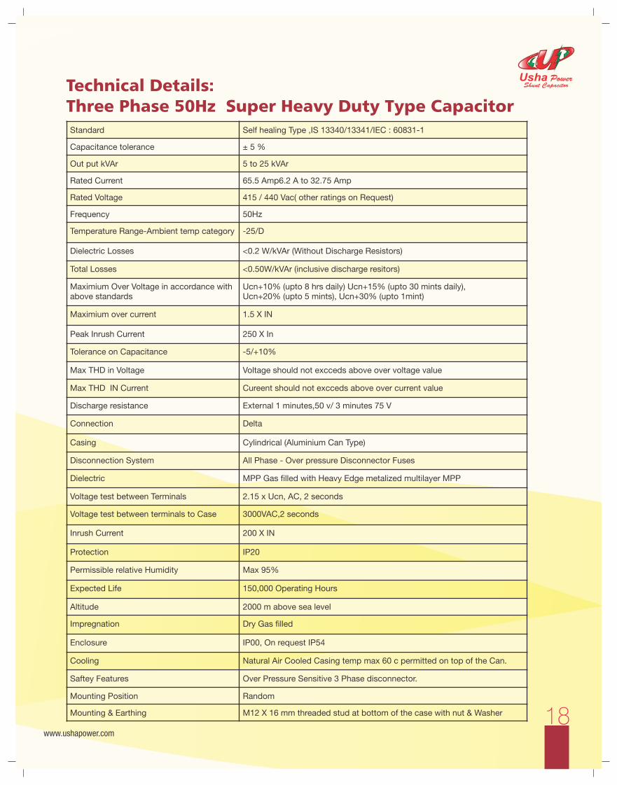
PFC SizingCapacitor (kVAr) Selection Chart
Coefficient K
Initial Value
Cosφ
(PF Obtainable)
tgφ
cosφ
0.85
0.86
0.87
0.88
0.89
0.90
0.91
0.92
0.93
0.94
0.95
0.96 0.97 0.98 0.99 1.00
3.18
0.30
2.560
2.586
2.613
2.640
2.667
2.695
2.724
2.754
2.785
2.817
2.851
2.888 2.929 2.977 3.037 3.180
3.07
0.31
2.447
2.474
2.500
2.527
2.555
2.583
2.611
2.641
2.672
2.704
2.738
2.775 2.816 2.864 2.924 3.067
2.96
0.32
2.341
2.367
2.394
2.421
2.448
2.476
2.505
2.535
2.565
2.598
2.632
2.669 2.710 2.758 2.818 2.961
2.86
0.33
2.241
2.267
2.294
2.321
2.348
2.376
2.405
2.435
2.465
2.498
2.532
2.569 2.610 2.657 2.718 2.861
2.77
0.34
2.146
2.173
2.199
2.226
2.254
2.282
2.310
2.340
2.371
2.403
2.437
2.474 2.515 2.563 2.623 2.766
2.68
0.35
2.057
2.083
2.110
2.137
2.164
2.192
2.221
2.250
2.281
2.313
2.348
2.385 2.426 2.473 2.534 2.676
2.59
0.36
1.972
1.998
2.025
2.052
2.079
2.107
2.136
2.166
2.196
2.229
2.263
2.300 2.341 2.388 2.449 2.592
2.51
0.37
1.891
1.918
1.944
1.971
1.999
2.027
2.055
2.085
2.116
2.148
2.182
2.219 2.260 2.308 2.368 2.511
2.43
0.38
1.814
1.841
1.867
1.894
1.922
1.950
1.979
2.008
2.039
2.071
2.105
2.143 2.184 2.231 2.292 2.434
2.36
0.39
1.741
1.768
1.794
1.821
1.849
1.877
1.905
1.935
1.966
1.998
2.032
2.069 2.110 2.158 2.219 2.361
2.29
0.40
1.672
1.698
1.725
1.752
1.779
1.807
1.836
1.865
1.896
1.928
1.963
2.000 2.041 2.088 2.149 2.291
2.22
0.41
1.605
1.631
1.658
1.685
1.712
1.740
1.769
1.799
1.829
1.862
1.896
1.933 1.974 2.022 2.082 2.225
2.16
0.42
1.541
1.567
1.594
1.621
1.648
1.676
1.705
1.735
1.766
1.798
1.832
1.869 1.910 1.958 2.018 2.161
2.10
0.43
1.480
1.506
1.533
1.560
1.587
1.615
1.644
1.674
1.704
1.737
1.771
1.808 1.849 1.897 1.957 2.100
2.04
0.44
1.421
1.448
1.474
1.501
1.529
1.557
1.585
1.615
1.646
1.678
1.712
1.749 1.790 1.838 1.898 2.041
1.98
0.45
1.365
1.391
1.418
1.445
1.472
1.500
1.529
1.559
1.589
1.622
1.656
1.693 1.734 1.781 1.842 1.985
1.93
0.46
1.311
1.337
1.364
1.391
1.418
1.446
1.475
1.504
1.535
1.567
1.602
1.639 1.680 1.727 1.788 1.930
1.88
0.47
1.258
1.285
1.311
1.338
1.366
1.394
1.422
1.452
1.483
1.515
1.549
1.586 1.627 1.675 1.736 1.878
1.83
0.48
1.208
1.234
1.261
1.288
1.315
1.343
1.372
1.402
1.432
1.465
1.499
1.536 1.577 1.625 1.685 1.828
1.78
0.49
1.159
1.186
1.212
1.239
1.267
1.295
1.323
1.353
1.384
1.416
1.450
1.487 1.528 1.576 1.637 1.779
1.73
0.50
1.112
1.139
1.165
1.192
1.220
1.248
1.276
1.306
1.337
1.369
1.403
1.440 1.481 1.529 1.590 1.732
1.69
0.51
1.067
1.093
1.120
1.147
1.174
1.202
1.231
1.261
1.291
1.324
1.358
1.395 1.436 1.484 1.544 1.687
1.64
0.52
1.023
1.049
1.076
1.103
1.130
1.158
1.187
1.217
1.247
1.280
1.314
1.351 1.392 1.440 1.500 1.643
1.60
0.53
0.980
1.007
1.033
1.060
1.088
1.116
1.144
1.174
1.205
1.237
1.271
1.308 1.349 1.397 1.458 1.600
1.56
0.54
0.939
0.965
0.992
1.019
1.046
1.074
1.103
1.133
1.163
1.196
1.230
1.267 1.308 1.356 1.416 1.559
1.52
0.55
0.899
0.925
0.952
0.979
1.006
1.034
1.063
1.092
1.123
1.156
1.190
1.227 1.268 1.315 1.376 1.518
1.48
0.56
0.860
0.886
0.913
0.940
0.967
0.995
1.024
1.053
1.084
1.116
1.151
1.188 1.229 1.276 1.337 1.479
1.44
0.57
0.822
0.848
0.875
0.902
0.929
0.957
0.986
1.015
1.046
1.079
1.113
1.150 1.191 1.238 1.299 1.441
1.40
0.58
0.785
0.811
0.838
0.865
0.892
0.920
0.949
0.979
1.009
1.042
1.076
1.113 1.154 1.201 1.262 1.405
1.37
0.59
0.749
0.775
0.802
0.829
0.856
0.884
0.913
0.942
0.973
1.006
1.040
1.077 1.118 1.165 1.226 1.368
1.33
0.60
0.714
0.740
0.767
0.794
0.821
0.849
0.878
0.907
0.938
0.970
1.005
1.042 1.083 1.130 1.191 1.333
1.30
0.61
0.679
0.706
0.732
0.759
0.787
0.815
0.843
0.873
0.904
0.936
0.970
1.007 1.048 1.096 1.157 1.299
1.27
0.62
0.646
0.672
0.699
0.726
0.753
0.781
0.810
0.839
0.870
0.903
0.937
0.974 1.015 1.062 1.123 1.265
1.23
0.63
0.613
0.639
0.666
0.693
0.720
0.748
0.777
0.807
0.837
0.870
0.904
0.941 0.982 1.030 1.090 1.233
1.20
0.64
0.581
0.607
0.634
0.661
0.688
0.716
0.745
0.775
0.805
0.838
0.872
0.909 0.950 0.998 1.058 1.201
1.17
0.65
0.549
0.576
0.602
0.629
0.657
0.685
0.714
0.743
0.774
0.806
0.840
0.877 0.919 0.966 1.027 1.169
1.14
0.66
0.519
0.545
0.572
0.599
0.626
0.654
0.683
0.712
0.743
0.775
0.810
0.847 0.888 0.935 0.996 1.138
1.11
0.67
0.488
0.515
0.541
0.568
0.596
0.624
0.652
0.682
0.713
0.745
0.779
0.816 0.857 0.905 0.966 1.108
1.08
0.68
0.459
0.485
0.512
0.539
0.566
0.594
0.623
0.652
0.683
0.715
0.750
0.787 0.828 0.875 0.936 1.078
1.05
0.69
0.429
0.456
0.482
0.509
0.537
0.565
0.593
0.623
0.654
0.686
0.720
0.757 0.798 0.846 0.907 1.049
1.02
0.70
0.400
0.427
0.453
0.48
0.508
0.536
0.565
0.594
0.625
0.657
0.692
0.729 0.770 0.817 0.878 1.020
0.99
0.71
0.372
0.398
0.425
0.452
0.480
0.508
0.536
0.566
0.597
0.629
0.663
0.700 0.741 0.789 0.849 0.992
0.96
0.72
0.344
0.370
0.397
0.424
0.452
0.480
0.508
0.538
0.569
0.601
0.635
0.672 0.713 0.761 0.821 0.964
0.94
0.73
0.316
0.343
0.370
0.396
0.424
0.452
0.481
0.510
0.541
0.573
0.608
0.645 0.686 0.733 0.794 0.936
0.91
0.74
0.289
0.316
0.342
0.369
0.397
0.425
0.453
0.483
0.514
0.546
0.580
0.617 0.658 0.706 0.766 0.909
0.88 0.75 0.262 0.289 0.315 0.342 0.370 0.398 0.426 0.456 0.487 0.519 0.553 0.590 0.631 0.679 0.739 0.882
0.86 0.76 0.235 0.262 0.288 0.315 0.343 0.371 0.400 0.429 0.460 0.492 0.526 0.563 0.605 0.652 0.713 0.855
0.83 0.77 0.209 0.235 0.262 0.289 0.316 0.344 0.373 0.403 0.433 0.466 0.500 0.537 0.578 0.626 0.686 0.829
0.80 0.78 0.183 0.209 0.236 0.263 0.290 0.318 0.347 0.376 0.407 0.439 0.474 0.511 0.552 0.599 0.660 0.802
0.78 0.79 0.156 0.183 0.209 0.236 0.264 0.292 0.320 0.350 0.381 0.413 0.447 0.484 0.525 0.573 0.634 0.776
0.75 0.80 0.130 0.157 0.183 0.210 0.238 0.266 0.294 0.324 0.355 0.387 0.421 0.458 0.499 0.547 0.608 0.750
0.72 0.81 0.104 0.131 0.157 0.184 0.212 0.240 0.268 0.298 0.329 0.361 0.395 0.432 0.473 0.521 0.581 0.724
0.70 0.82 0.078 0.105 0.131 0.158 0.186 0.214 0.242 0.272 0.303 0.335 0.369 0.406 0.447 0.495 0.556 0.698
0.67 0.83 0.052 0.079 0.105 0.132 0.160 0.188 0.216 0.246 0.277 0.309 0.343 0.380 0.421 0.469 0.530 0.672
0.65 0.84 0.026 0.053 0.079 0.106 0.134 0.162 0.190 0.220 0.251 0.283 0.317 0.354 0.395 0.443 0.503 0.646
0.62 0.85 0.026 0.053 0.080 0.107 0.135 0.164 0.194 0.225 0.257 0.291 0.328 0.369 0.417 0.477 0.620
0.59 0.86 0.027 0.054 0.081 0.109 0.138 0.167 0.198 0.230 0.265 0.302 0.343 0.390 0.451 0.593
0.57 0.87 0.027 0.054 0.082 0.111 0.141 0.172 0.204 0.238 0.275 0.316 0.364 0.424 0.567
0.54 0.88 0.027 0.055 0.084 0.114 0.145 0.177 0.211 0.248 0.289 0.337 0.397 0.540
0.51 0.89 0.028 0.057 0.086 0.117 0.149 0.184 0.221 0.262 0.309 0.370 0.512
0.48 0.90 0.029 0.058 0.089 0.121 0.156 0.193 0.234 0.281 0.342 0.484
0.46 0.91 0.030 0.060 0.093 0.127 0.164 0.205 0.253 0.313 0.456
0.43 0.92 0.031 0.063 0.097 0.134 0.175 0.223 0.284 0.426
Coefficient K by which to multiply the active energy consumed in kW in order to determine the kVAr necessary for correcting the Power Factor (cosφ0is the initial PF, cosφ1, is the PF obtainable with correction). Recommended final cosφ= 0.95 (greyed column below).

Example:If in an Electricity Bill,
Contract Demand (CD) = 250 kVAMaximum Demand (MD) = 220 kVA
Consider the Power Factor (PF) = 0.92Then,
Required kVAr (Qc) = CD/MD x Existing Pf x Multiplying Factor (from table)= 250 x 0.92 x 0.426= 97.98 (assume 100 kVAr)
For the Improvement of the Power Factor from 0.92 to Unity. We read the factor 0.426 from the table
NOTE: The greater amount of kVA should be taken into consideration for calculation, i.e. If MD > CD then, kVA of MD should be calculated or vice versa.
30www.ushapower.com
Usha PowerShunt Capacitor
Correcting the Power Factor of MV/ LV TransformerIt is always a good idea to ensure a Power Factor correction for MV/ LV transformers, since even when they are operating load less (e.g. during the night) they absorb reactive power, which must be compensated.The exact Capacitor Power necessary may be calculated using the formula below:
Q= l0%.Pn / 100
L0 = load less current(Specified by the transformer manufacturer)Pn = rated power of the transformerAlternatively, if the required data is not available, you can refer to the table below, which differentiates among types of transformers with NORMAL losses.
Power Transformer kVa
Oil Transformer kVAr
Resin Transformer kVAr
10 1 1,5
20 2 1,7
50 4 2
75 5 2,5
100 5 2,5
160 7 4
200 7,5 5
250 8 7,5
315 10 7,5
400 12,5 8
Power Transformer kVa
Oil Transformer kVAr
Resin Transformer kVAr
500 15 10
630 17,5 12,5
800 20 15
1000 25 17,5
1250 30 20
1600 35 22
2000 40 25
2500 50 35
3150 60 50

Our Focussed
Power Generation Plants
FMCG
Steel IndustriesCement Industries
Aluminium Industries
Textile Industries
Market Segment
32www.ushapower.com
Usha PowerShunt Capacitor

A Small List of OurSatisfied Customers
33www.ushapower.com
Usha PowerShunt Capacitor

www.ushapower.com
Usha PowerShunt Capacitor
an exciting‘‘
futurea successful past

Head/Registered OfficeUsha Tower, 162A, Dumdum Park,
Kolkata-700055, West Bengal, India
Phone: +91 33 2590 8012 / 8720
Fax: +91 33 2590 8012
Mobile: +91 92316 83557
E-mail: [email protected]
www.ushapower.com
Corporate OfficeA-215/09, Ground Floor, Street No. 1,
“CHAWLA COMPLEX” Vikas Marg, Shakarpur,
New Delhi – 110092, India
Phone: (011) 22453829
Mobile: +91 93119 86643
Mobile: +91 88260 18055
Email: [email protected]
Raipur OfficeC-2, Maruti Enclave, Tatibandh, Raipur,
Chattisgarh-492 099
(M) +91 93001 02456
Email: [email protected]
WorksKolkata,
(M) +91 93311 60677
Pune, Noida
Other OfficesAhmedabad: +91 9332356984
Guwahati: +91 9331460669
Jaipur: +91 9311986643
Pune: +91 8698804924
ww
w.w
ingsm
edia
.co.in
+91 9
830939253
24hour
602 8 18 8 01 59 5+
Australia
Asia
AfricaSouth America
EuropeNorth America
India
Global Presence