USFS Dry Hydrant Manual
48
DRY HYDRANT MANUAL ., •••••• 1 ••••••••••••••• :::::!:HHiH:H;:::H; A Guide for Developing Alternative Water Sources and Delivery Systems for Rural Fire Protection I
Transcript of USFS Dry Hydrant Manual
DRY HYDRANT MANUAL
., •••••• 1 •••••••••••••••:::::!:HHiH:H;:::H;
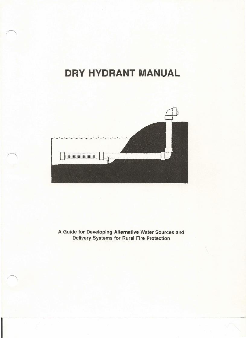
A Guide for Developing Alternative Water Sources andDelivery Systems for Rural Fire Protection
I
DRY HYDRANT MANUAL
A Guide for Developing Alternative Water Sources andDelivery Systems for Rural Fire Protection
USDA Forest ServiceSouthern Region
1720 Peachtree Road, NWAtlanta, GA 30367-9102
The use of trade or firm names in this publication is for readerinformation and does not imply endorsement by the
U.S. Department of Agriculture or any product or service.
The facilities, programs, and services of the Forest Service and the National Forests are for the use and enjoyment of allpeople. Discrimination against any persons because of race, color, national origin,sex, age, religion, or disability is strictlyagainst the policy of the USDA Forest Service, and should be reported to the Secretary of Agriculture, Washington, D.C.20250
Technical Publication R8-TP 19 September 1993
I
ACKNOWLEDGEMENTS
The second printing of the manual offers the reader the latest information on the planning, design,installation and water delivery system for rural fire fighting.
Representatives from the following groups ,or agencies participated in the revision of this manual.
-USDA Forest Service-Georgia Forestry Commission-Georgia RC&D Council-Chestatee-Chattahoochee RC&D Council-USDA Soil Conservation Service (SCS)-Georgia Office of Energy Resources-National Fire Protection Association
Funds for this reprint and revision were provided by the USDA Forest Service Fire and AviationManagement, Southern Region, 1720 Peachtree Road, N.W., Atlanta, GA.
Appreciation is once again extended to all individuals and organizations who contributed to the originaledition of the manual. Your efforts have served to enhance the level of fire protection across the nation.
I
I

CHAPTER I
INTRODUCTION
Dry Hydrant Fire Fighting Concept
A dry hydrant is a non-pressurized pipe permanently installed in existing lakes, ponds, or streams thatprovides a means of suction supply of water to a tank truck. The dry hydrant system concept includes not onlythe strategic location of the hydrant itself, but also the equipment and trained personnel to use it efficiently. Allthree of these components are essential for an effective dry hydrant system. The concept is not new. Many firedepartments have successfully used dry hydrants for a number of years, but their use has not been wide-spread until recently.
In many rural areas, a lack of water mains and domestic fire hydrants can sometimes impair a firedepartment's ability to do its job quickly and efficiently. Tanker trucks must be used to carry large amounts ofwater to the fire scene. The success of the operation hinges on the distance the trucks must travel to water"fill-up" points around the county. Unfortunately, the fill-up points are often a long distance from the fire, andfire-fighters are unable to retain an uninterrupted water supply at the scene in many cases.
Some counties have begun to take advantage of "natural water sources" for fire-fighting. Most areashave a number of privately owned ponds, lakes and streams that could be used, with permission, as fill-uppoints.
The installation of a non-pressurized pipe system into these water sources provides a ready means of asuction-supply of water to tank trucks. The dry hydrant system gives the pumping units access to the pondsand streams from the main road. As in figure 1, one end of the dry hydrant sticks out of the ground to givetankers a hose connection, and the other end is a strainer submerged in the pond or stream to draw waterdirectly through the system.
The dry hydrant can be made of any hard, permanent material (steel, iron); however, polyvinylchloride (PVC) is becoming commonly used due to price, accessibility and low friction loss-performance.The other elements of the system include an intake strainer section, hydrant head with suction screen and cap.All component parts should be expertly engineered and built for trouble-free service.
NOTE: All references to tank truck in this publication means the same as tender or mobile water supply.
5" Oap . Steamer
/
Hose Connection
6" Elbow[)qt24~ +--- 6- Riser
Rod & Cotter Keyto HoldStrainer Cap On _
StrainerCap
I ,~;:",~jdFigure 1.- Enlarged view of dry hydrant construction.
1-1
I
Benefits of Dry Hydrant System
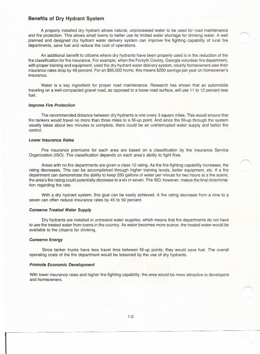
A properly installed dry hydrant allows natural, unprocessed water to be used for road maintenanceand fire protection. This allows small towns to better use its limited water shortage for drinking water. A wellplanned and designed dry hydrant water delivery system can improve fire fighting capability of rural firedepartments, save fuel and reduce the cost of operations.
An additional benefit to citizens where dry hydrants have been properly used is in the reduction of thefire classification for fire insurance. For example, when the Forsyth County, Georgia volunteer fire department,with proper training and equipment, used the dry hydrant water delivery system, county homeowners saw theirinsurance rates drop by 49 percent. For an $85,000 home, this means $200 savings per year on homeowner'sinsurance.
Water is a key ingredient for proper road maintenance. Research has shown that an automobiletraveling on a well-compacted gravel road, as opposed to a loose road surface, will use 11 to 12 percent lessfuel.
Improve Fire Protection
The recommended distance between dry hydrants is one every 3 square miles. This would ensure thatfire tankers would travel no more than three miles to a fill-up point. And since the fill-up through the systemusually takes about two minutes to complete, there could be an uninterrupted water supply and better firecontrol.
Lower Insurance Rates
Fire insurance premiums for each area are based on a classification by the Insurance ServiceOrganization (ISO). The classification depends on each area's ability to fight fires.
Areas with no fire departments are given a class 10 rating. As the fire-fighting capability increases, therating decreases. This can be accomplished through higher training levels, better equipment, etc. If a firedepartment can demonstrate the ability to keep 250 gallons of water per minute for two hours at a fire scene,the area's fire rating could potentially decrease to a six or seven. The ISO, however, makes the final determina-tion regarding the rate.
With a dry hydrant system, this goal can be easily achieved. A fire rating decrease from a nine to aseven can often reduce insurance rates by 45 to 50 percent.
Conserve Treated Water Supply
Dry hydrants are installed in untreated water supplies, which means that fire departments do not haveto use the treated water from towns in the country. As water becomes more scarce, the treated water would beavailable to the citizens for drinking.
Conserve Energy
Since tanker trucks have less travel time between fill-up points, they would save fuel. The overalloperating costs of the fire department would be lessened by the use of dry hydrants.
Promote Economic Development
With lower insurance rates and higher fire-fighting capability, the area would be more attractive to developersand homeowners.
1-2
I
Improve Road Maintenance
A large amount of water is usually needed for the installation of the base on gravel roads. The waterallows for better compacting of the road, which will often improve gas mileage for cars that travel on it.
Preplanning
A number of preplanning activities should take place by local government or community fire depart-ments as a prerequisite to the consideration of dry hydrants.
A master fire plan should be developed stating goals and objectives for rural fire protection. The planshould serve as the guide for organization, equipment, training, and water supply needs to reach the level offire protection desired. Assistance in developing such a plan is available from the State forestry commissionRFD coordinator.
Plans should include, but are not limited to:
a. Equipment (large-chassis, pumpers, tankers, ladder units, other rolling stock.)b. Equipment (support, accessory, and personnel)c. Manpowerd. Training, equipment and facilitiese. Building(s) - new, renovation, additionf. lnspections - commercial building, residential (all types), hospitals, schools, homes for the elderly,
fire hydrants and water supply points.g. I and E - public education, fire preventionh. Water supply improvements for fire protection
Local county or city governments are encouraged to set up an organizational structure to allow com-munity volunteer fire departments to work together to promote dry hydrants for maximum benefit. Ideally,the county/city government should have a full time fire coordinator to work with volunteer fire districts im-plementing the goals and objectives of the master fire plan, including the implementation of the dry hydrantwater delivery system.
"\-3
I
CHAPTER II
SELECTING HYDRANT LOCATIONS
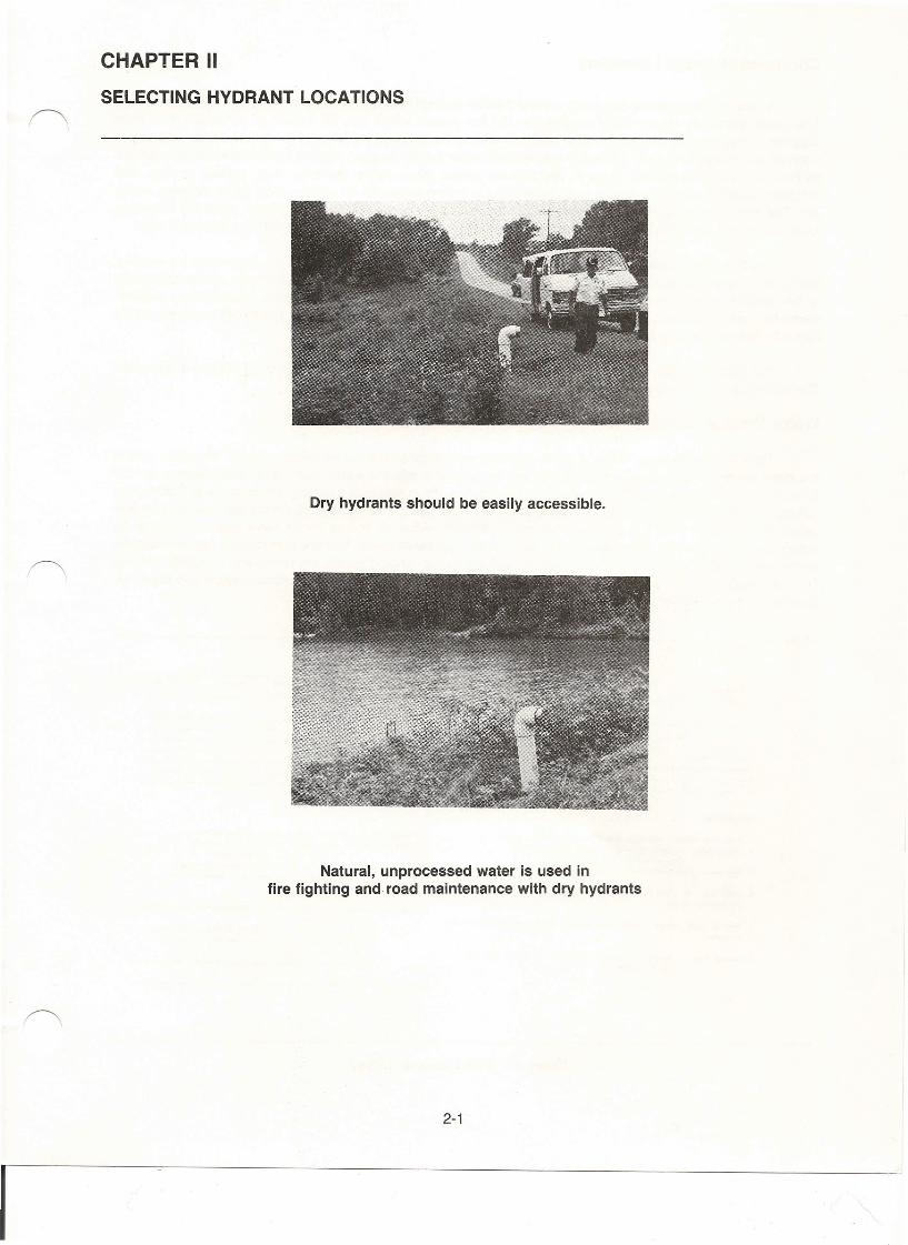
Dry hydrants should be easily accessible.
Natural, unprocessed water is used infire fighting and road maintenance with dry hydrants
2-1
I
Choosing Hydrant Locations
A rural fire department operating without a water system has two means of getting the necessary water.The department may obtain water supplies on the fire scene, which may be natural or constructed, or fromsupplies transported to the scene. Dry hydrants should be strategically located in natural water sources atintervals necessary to supply adequate and reliable water supply all year. Natural bodies of water are definedas bodies of water contained by earth, and include ponds, lakes, rivers, streams, bays, creeks, springs, andirrigation canals. Constructed sources of water include swimming pools, elevated gravity tanks, cisterns, wells,etc. The total water supply for suburban and rural fire fighting from all sources should meet the minimumrequirements as set forth in chapter V of the National Fire Protection Association (NFPA) Standard 1231.
The fact that a water source is in sight of the main road does not assure that the water may be used forfire fighting purposes. Some circumstances necessitate developing alternative approaches and accessabilityof fire vehicles. It is advisable to consult highway officials, particularly if on State roads, to determine require-ments for parking on roadways or bridges for fire operations. In some states, a fire department is not allowed touse a bridge or roadway to park a fire unit while it is being filled.
It is also advisable to become familiar with road conditions and ratings of existing bridges in the area.The county or State road department will have this information.
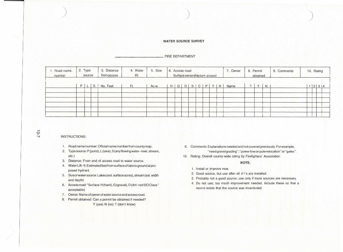
Water Source Survey
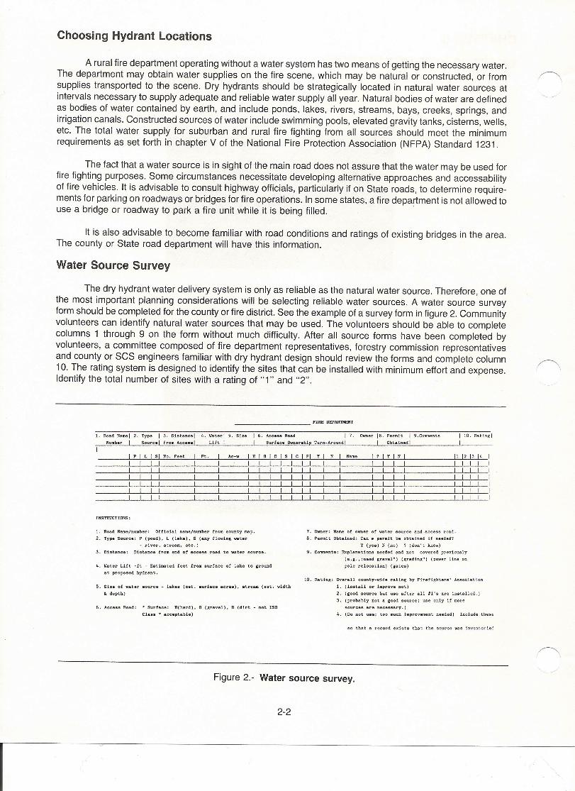
The dry hydrant water delivery system is only as reliable as the natural water source. Therefore, one ofthe most important planning considerations will be selecting reliable water sources. A water source surveyform should be completed for the county or fire district. See the example of a survey form in figure 2. Communityvolunteers can identify natural water sources that may be used. The volunteers should be able to completecolumns 1 through 9 on the form without much difficulty. After all source forms have been completed byvolunteers, a committee composed of fire department representatives, forestry commission representativesand county or SCS engineers familiar with dry hydrant design should review the forms and complete column10. The rating system is designed to identify the sites that can be installed with minimum effort and expense.Identify the total number of sites with a rating of "1" and "2".
______________ P~D~~
1. Road Name I 2. Type I 3. maeence l 4. Water I 5. Size I 6. Acceu Road I 7. Owner 18. Permit I 9.Comments
Number I Source I from Access I Lift I I Surface Ownership Turn-Around I I Obtained!
I 10. Rating)
I
I p I L I s 1 No. Peet I Pt. Ac-w 1 H 1 G 1 D 1 s 1 c I pi y 1 N Name 11 12 13 141 1 I I 1 I II 1 I I I I I1 I I I I I II I I 1 I 1 I1 1 I 1 I I I1 1 I 1 I I I
INSTRUCTIONS:
1. Road Name/number: Official name/number from county map.
2. Type Source: P (pond). L (lake). S (any flowing water
- river. stream. etc.)
3. Distance: Distance from end of access road to water source.
7. Owner: Name of owner of water source end access road.
8. Permit Obtained: Can a permit be obtained if needed?
Y (yes) N (no) ? (don't know)
9. Comments: Explenations needed and not covered previously
(e.g .• :need gravel") (grading") (power line on
pole relocation) (gates)4. Water Lift -ft - Estimated feet from surface of lake to ground
at proposed h.ydrant.
5. Size of water source - lakes (est. surface acres). stream (eee • width
to. depth)
10. Rating: Overall county-wide rating by Firefighters' Association
1. (inetall or improve not)
2. (good source but use after all #l's are installed.)
3. (probably not a good source; use only if more
sources are necessary.)
4. (Do not use: too much improvement needed) Include these
6. Access Road: * Surface: H(hard). G (gravel). D (dirt - not ISO
Class· acceptable)
so that a record exists that the source was inventoried
Figure 2.- Water source survey.
2-2
I
Mapping
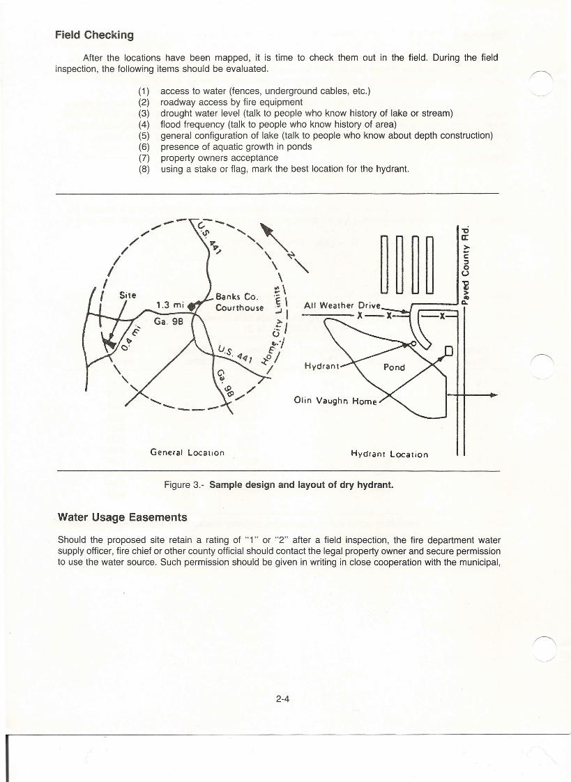
Using a county road map, mark the good sites (Rating of "1" and "2") on the map. See examplein figure 3. A study of the Master Fire Plan for the county and above discussed map showing possible dryhydrant sites will assist county planners in selecting strategic hydrant sites for water supply.
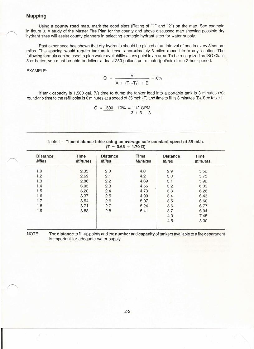
Past experience has shown that dry hydrants should be placed at an interval of one in every 3 squaremiles. This spacing would require tankers to travel approximately 3 miles round trip to any location. Thefollowing formula can be used to plan water availability at any point in an area. To be recognized as ISO Class8 or better, you must be able to deliver at least 250 gallons per minute (gailmin) for a 2-hour period.
EXAMPLE:
Q v------- -10%A + (T1-T2) + B
If tank capacity is 1,500 gal. (V) time to dump the tanker load into a portable tank is 3 minutes (A);round-trip time to the refill point is 6 minutes at a speed of 35 mph (T) and time to fill is 3 minutes (B). See table 1.
Q = 1500-10% = 112 GPM3+6+3
Table 1 - Time distance table using an average safe constant speed of 35 mi/h.(T = 0.65 + 1.70 D)
Distance Time Distance Time Distance TimeMiles Minutes Miles Minutes Miles Minutes
1.0 2.35 2.0 4.0 2.9 5.521.2 2.69 2.1 4.2 3.0 5.751.3 2.86 2.2 4.39 3.1 5.921.4 3.03 2.3 4.56 3.2 6.091.5 3.20 2.4 4.73 3.3 6.261.6 3.37 2.5 4.90 3.4 6.431.7 3.54 2.6 5.07 3.5 6.601.8 3.71 2.7 5.24 3.6 6.771.9 3.88 2.8 5.41 3.7 6.94
4.0 7.454.5 8.30
NOTE: The distance to fill-up points and the number and capacity of tankers available to a fire departmentis important for adequate water supply.
2-3
I
Field Checking
After the locations have been mapped, it is time to check them out in the field. During the fieldinspection, the following items should be evaluated.
(1) access to water (fences, underground cables, etc.)(2) roadway access by fire equipment(3) drought water level (talk to people who know history of lake or stream)(4) flood frequency (talk to people who know history of area)(5) general configuration of lake (talk to people who know about depth construction)(6) presence of aquatic growth in ponds(7) property owners acceptance(8) using a stake or flag, mark the best location for the hydrant.
--/
"//
/I
II
"'0a::>-c~ooi>'II~ __ ~o.
Olin Vaughn Home
General Location Hydrant Location
Figure 3.- Sample design and layout of dry hydrant.
Water Usage Easements
Should the proposed site retain a rating of "1" or "2" after a field inspection, the fire department watersupply officer, fire chief or other county official should contact the legal property owner and secure permissionto use the water source. Such permission should be given in writing in close cooperation with the municipal,
2-4
I
town or country attorney. It is recommended that the easement be reviewed by a representative of the high-way or county road department or others who will be required to build, service and maintain access roadsand areas adjacent to hydrants.
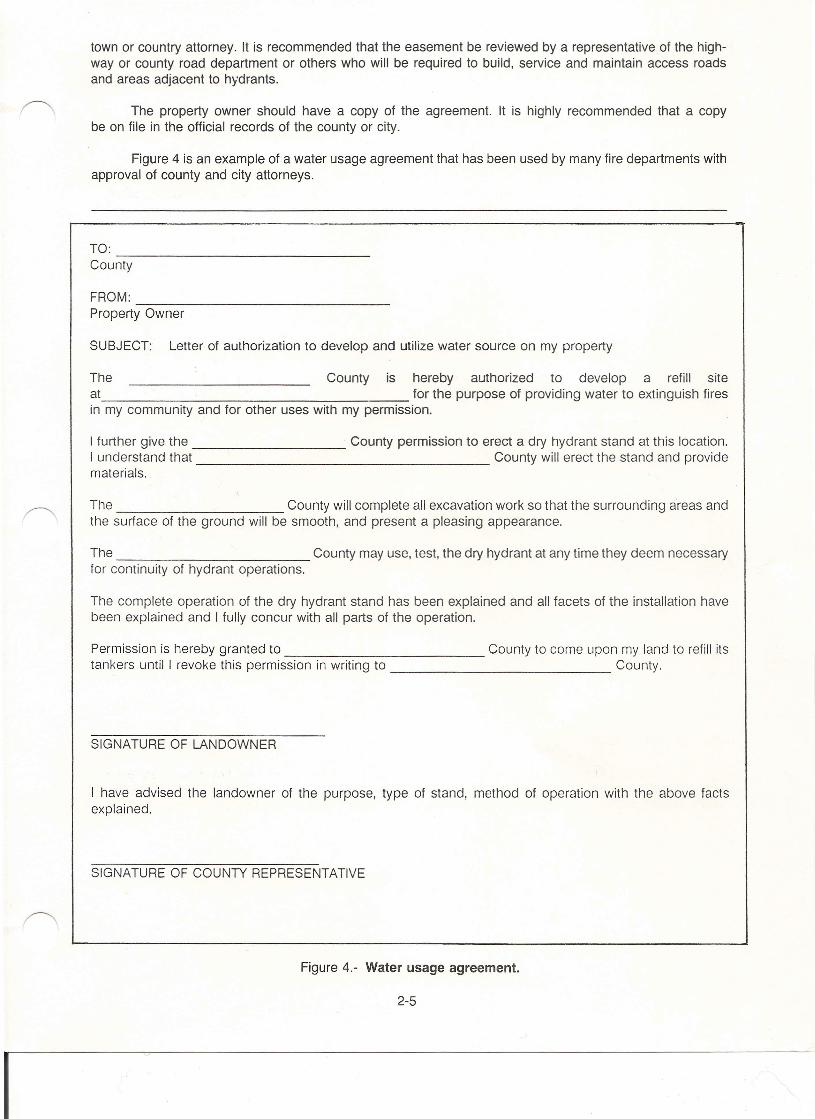
The property owner should have a copy of the agreement. It is highly recommended that a copybe on file in the official records of the county or city.
Figure 4 is an example of a water usage agreement that has been used by many fire departments withapproval of county and city attorneys.
TO: --------------------------------County
FROM: ~~----------------------------Property Owner
SUBJECT: Letter of authorization to develop and utilize water source on my property
The County is hereby authorized to develop a refill siteat for the purpose of providing water to extinguish firesin my community and for other uses with my permission.
I further give the County permission to erect a dry hydrant stand at this location.I understand that County will erect the stand and providematerials.
The County will complete all excavation work so that the surrounding areas andthe surface of the ground will be smooth, and present a pleasing appearance.
The County may use, test, the dry hydrant at any time they deem necessaryfor continuity of hydrant operations.
The complete operation of the dry hydrant stand has been explained and all facets of the installation havebeen explained and I fully concur with all parts of the operation.
Permission is hereby granted to County to come upon my land to refill itstankers until I revoke this permission in writing to County.
SIGNATURE OF LANDOWNER
I have advised the landowner of the purpose, type of stand, method of operation with the above factsexplained.
SIGNATURE OF COUNTY REPRESENTATIVE
I
Figure 4.- Water usage agreement.
2-5
CHAPTER III
SURVEY AND DESIGN
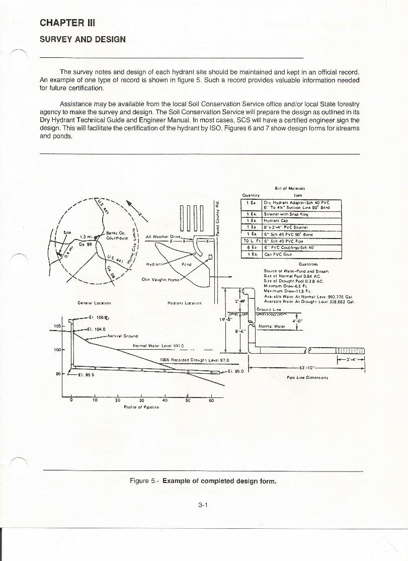
The survey notes and design of each hydrant site should be maintained and kept in an official record.An example of one type of record is shown in figure 5. Such a record provides valuable information neededfor future certification.
Assistance may be available from the local Soil Conservation Service office and/or local State forestryagency to make the survey and design. The Soil Conservation Service will prepare the design as outlined in itsDry Hydrant Technical Guide and Engineer Manual. In most cases, SCS will have a certified engineer sign thedesign. This will facilitate the certification of the hydrant by ISO. Figures 6 and 7 show design forms for streamsand ponds.
Quantity It om--/;'/
I'II
II
,,--.... ,...to •••.•. "... ,
" \ ~\ "-\~\~\-'I6/r/
.:to //
1 Ea. Dry Hydrant Adaptor-Sch .a PVC6" To ~l\" SUCt,on Lme 90' Bt""
1 Ea. Strainer with Sn.p Ring
1 Ea. Hydrant c..plEa 6..• 3·••.. PYC 5t"i"",
, 1 Ea. 6" Sch ~O PYC 90" Be""70 L. FI 6" Sch ~O PYC P,pt
6 e. 6" PVC COUpli"'ij,·Sch ~oI ea. Can PVC Glut
General t.ocancn Hvdranl t ocauon
Ouantitin
Source 01 Water-Pond and StreamS,,. of Norm.1 Pool 0.B4 AC.Size of Drought Pool 0.38 AC.Minimum 0"",-6.5 Fl.Ma.imum Dra",-".5 Ft.Ava,lable Wate, AI Normal Ltvel 993.770 G.I.Ava"able Wa re r At Drought Level 338.862 Gal.
95
1054'-{)"
Normal Water i
100Normal Water Lev.1 1(lIl 0
1986 Rocorded D,ought Level 97.0
_------63·-10 ..
o 10 20 30 ~o 60 60Prof ile of Pipeline
Figure 5.- Example of completed design form.
3-1
I
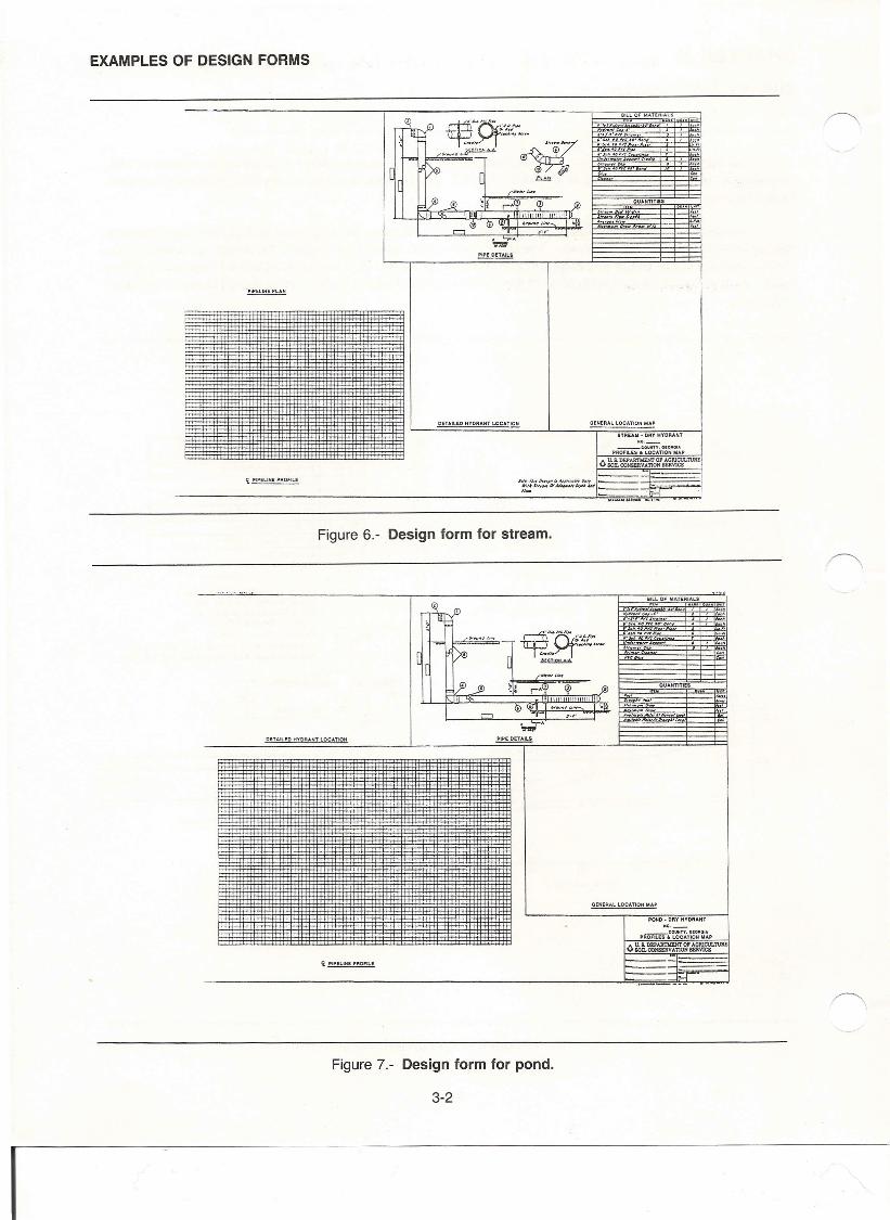
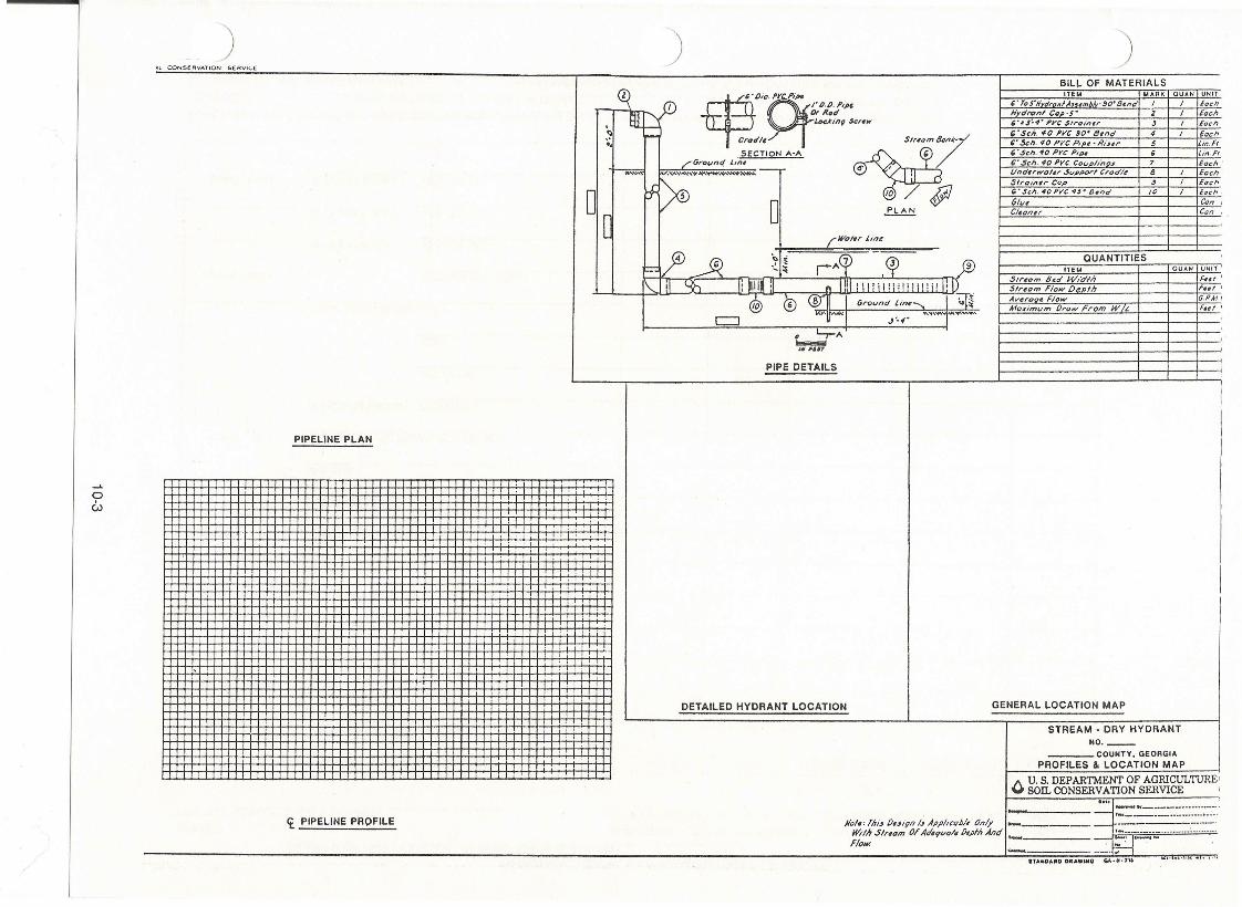
EXAMPLES OF DESIGN FORMS
GENERAL LOCATION MAPoeTAILED HYDRANT LOCATION
-----STREAU • DRY HYDRANT
110. _
__ ~oUlln.Gtoaou.PROFILli • LOCATION MAP
Ii PIPELINE PROFILE lIoI.'F~16~,,,.llh";~""o..t~ _'J!:Jfr- NAN~lIuIitMd _---_ ..
Figure6.- Design form for stream.
10".
I••"
",.II
h'
I •• "
DETAILED HYDRANT LOCATION
OENERALlOCATlON MAP
POND. DRY HYDRANT110. _
__ CO\,lIlTY,OIO_OIAPROFILES' LOCATION WAP
A U.a DEPIJmlEHT 0' AORlCllI.'lVRE"" SOILCQliSEllVA'nON SERVICE
i PIPELINE PROFILE
Figure7.- Design form for pond.
3-2
I
If qualified engineering assistance is not available from local agency or private engineers, carry outthe following steps.
Field Survey
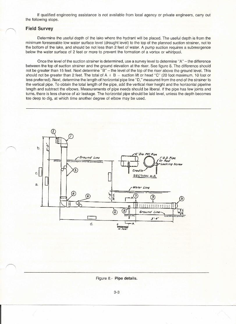
Determine the useful depth of the lake where the hydrant will be placed. The useful depth is from theminimum foreseeable low water surface level (drought level) to the top of the planned suction strainer, not tothe bottom of the lake, and should be not less than 2 feet of water. A pump suction requires a submergencebelow the water surface of 2 feet or more to prevent the formation of a vortex or whirlpool.
Once the level of the suction strainer is determined, use a survey level to determine "A" - the differencebetween the top of suction strainer and the ground elevation at the riser. See figure 8. The difference shouldnot be greater than 15 feet. Next determine "B" - the level of the top of the riser above the ground level. Thisshould not be greater than 2 feet. The total of A + B = suction lift or head "C" (20 foot maximum, 10 foot orless preferred). Next, determine the length of horizontal pipe line "D," measured from the end of the strainer tothe vertical pipe. To obtain the total length of the pipe, add the vertical riser height and the horizontal pipelinelength and subtract the elbows. Measurements of pipe needs should be liberal. If the pipe has few joints andturns, there is less chance of air leakage. The horizontal pipe should be laid level, unless the depth becomestoo deep to dig, at which time another degree of elbow may be used .
.~"'"
b. trP--DiD.Pre PiperO.D.pipe
- Or RotlruLocki"~$craw
crotlle.Yl
SECTION A-Ac·D ooa.
d.
Figure 8.- Pipe details.
3-3
I
•Design Features
Several factors should be considered when designing a dry hydrant: (A) desired flow from the hydrantin gallons per minute (gal/min). This will be affected by the distance to the water, difference in elevation betweenhydrant and water source and size of pipe; (B) suitability of the pipe materials. PVC (polyvinyl chloride) iscommonly used because of its many advantages. Other types of materials such as iron, concrete and fibermay be used if a water-tight connection is made; (C) size and type of pumper that is available.
The following design features are suggested for dry hydrants using PVC pipes.
A - Use a minimum of 6-inch pipes for dry hydrant construction.B - Schedule 40 pipe should be used.C - All exposed pipe should be primed and painted.D - Use a minimum number of elbows, preferably two. Elbows may be 90° or 45° bends.E - All connections should be properly jointed and cemented with few joints.F - Contact a supply firm to purchase the dry hydrant assembly (90° elbow, screen, coupling with
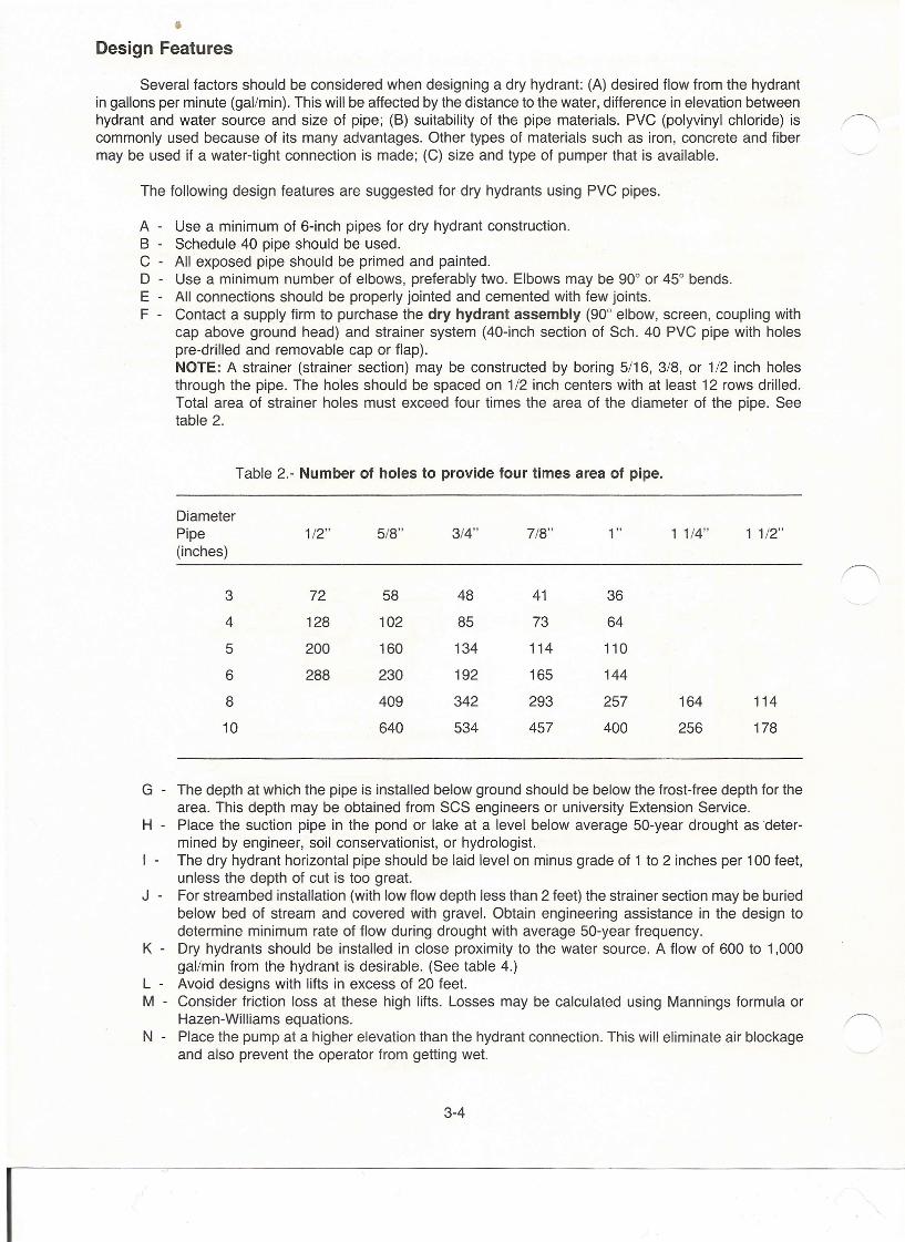
cap above ground head) and strainer system (40-inch section of Sch. 40 PVC pipe with holespre-drilled and removable cap or flap).NOTE: A strainer (strainer section) may be constructed by boring 5/16, 3/8, or 1/2 inch holesthrough the pipe. The holes should be spaced on 1/2 inch centers with at least 12 rows drilled.Total area of strainer holes must exceed four times the area of the diameter of the pipe. Seetable 2.
Table 2.- Number of holes to provide four times area of pipe.
DiameterPipe 1/2" 5/8" 3/4" 7/8" 1" 1 1/4" 1 1/2"(inches)
3 72 58 48 41 36
4 128 102 85 73 64
5 200 160 134 114 110
6 288 230 192 165 144
8 409 342 293 257 164 114
10 640 534 457 400 256 178
G - The depth at which the pipe is installed below ground should be below the frost-free depth for thearea. This depth may be obtained from SCS engineers or university Extension Service.
H - Place the suction pipe in the pond or lake at a level below average 50-year drought asdeter-mined by engineer, soil conservationist, or hydrologist.
I - The dry hydrant horizontal pipe should be laid level on minus grade of 1 to 2 inches per 100 feet,unless the depth of cut is too great.
J - For streambed installation (with low flow depth less than 2 feet) the strainer section may be buriedbelow bed of stream and covered with gravel. Obtain engineering assistance in the design todetermine minimum rate of flow during drought with average 50-year frequency.
K - Dry hydrants should be installed in close proximity to the water source. A flow of 600 to 1,000gal/min from the hydrant is desirable. (See table 4.)
L - Avoid designs with lifts in excess of 20 feet.M - Consider friction loss at these high lifts. Losses may be calculated using Mannings formula or
Hazen-Williams equations.N - Place the pump at a higher elevation than the hydrant connection. This will eliminate air blockage
and also prevent the operator from getting wet.
3-4
I
o - In areas where rock is encountered, each hydrant must be tailored to fit the rock profiles as muchas possible. This will create a detailed design and will normally involve more than the two con-ventional 90 degree bends. Carefully support the hydrant since quite often it has little support fromthe soils surrounding it.
Calculating Water Quantities
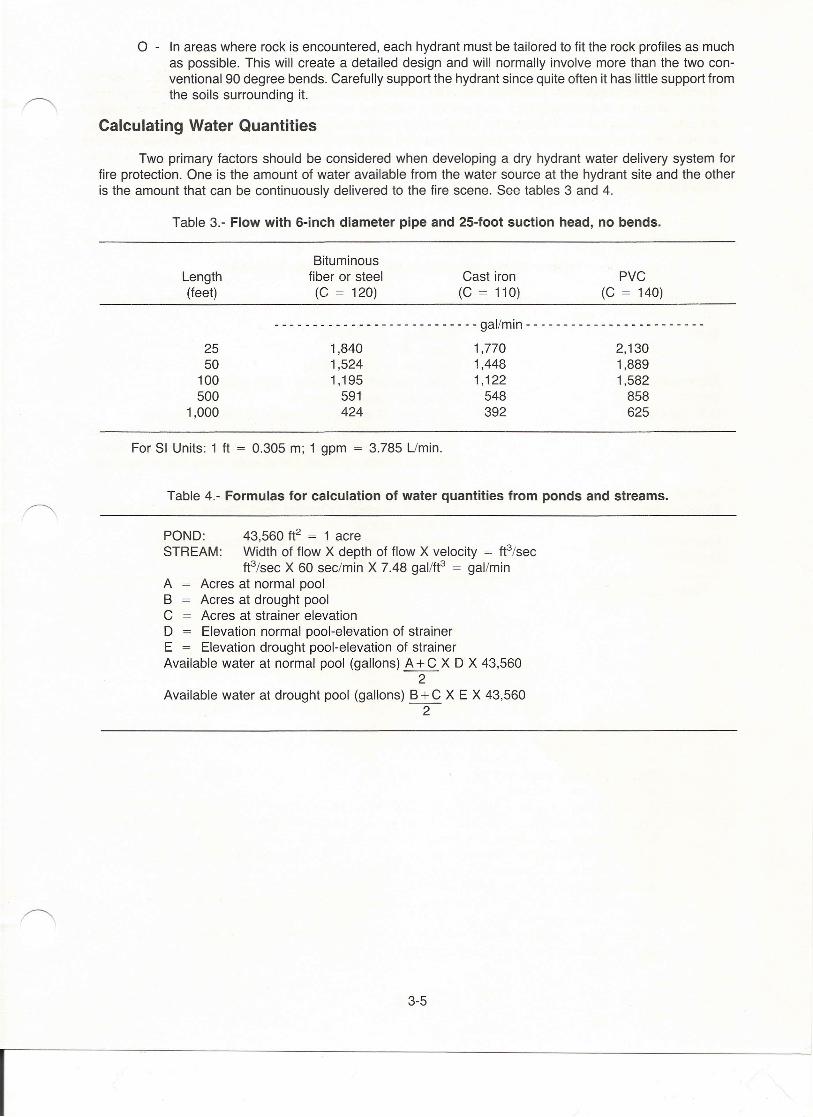
Two primary factors should be considered when developing a dry hydrant water delivery system forfire protection. One is the amount of water available from the water source at the hydrant site and the otheris the amount that can be continuously delivered to the fire scene. See tables 3 and 4.
Table 3.- Flow with 6-inch diameter pipe and 25-foot suction head, no bends.
Length(feet)
Bituminousfiber or steel
(C = 120)Cast iron
(C = 110)PVC
(C = 140)
- - - - - - - - - - - - - - - - - - - - - - - - - - - gal/min - - - - - - - - - - - - - - - - - - - - - - - -
25 1,840 1,770 2,13050 1,524 1,448 1,889
100 1,195 1,122 1,582500 591 548 858
1,000 424 392 625
For SI Units: 1 ft = 0.305 m; 1 gpm = 3.785 Llmin.
Table 4.- Formulas for calculation of water quantities from ponds and streams.
POND: 43,560 ft2 = 1 acreSTREAM: Width of flow X depth of flow X velocity = ft3/sec
ft3/sec X 60 sec/min X 7.48 gal/ft3 = gal/minA Acres at normal poolB Acres at drought poolC Acres at strainer elevationD Elevation normal pool-elevation of strainerE Elevation drought pool-elevation of strainerAvailable water at normal pool (gallons) A + C X D X 43,560
2Available water at drought pool (gallons) B +C X E X 43,560
2
3-5
I
Access to Water Supplies
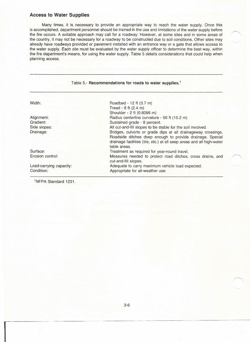
Many times, it is necessary to provide an appropriate way to reach the water supply. Once thisis accomplished, department personnel should be trained in the use and limitations of the water supply beforethe fire occurs. A suitable approach may call for a roadway. However, at some sites and in some areas ofthe country, it may not be necessary for a roadway to be constructed due to soil conditions. Other sites mayalready have roadways provided or pavement installed with an entrance way or a gate that allows access tothe water supply. Each site must be evaluated by the water supply officer to determine the best way, withinthe fire department's means, for using the water supply. Table 5 details considerations that could help whenplanning access.
Table 5.- Recommendations for roads to water supplies.'
Width:
Surface:Erosion control:
Roadbed - 12 ft (3.7 m)Tread - 8 ft (2.4 m)Shoulder - 2 ft (0.6096 m)Radius centerline curvature - 50 ft (15.2 m)Sustained grade - 8 percent.All cut-and-fill slopes to be stable for the soil involved.Bridges, culverts or grade dips at all drainageway crossings.Roadside ditches deep enough to provide drainage. Specialdrainage facilities (tile, etc.) at all seep areas and all high-watertable areas.Treatment as required for year-round travel.Measures needed to protect road ditches, cross drains, andcut-and-fill slopes.Adequate to carry maximum vehicle load expected.Appropriate for all-weather use.
Alignment:Gradient:Side slopes:Drainage:
Load-carrying capacity:Condition:
1NFPA Standard 1231.
3-6
I
CHAPTER IVINSTALLATION
PreplanningInstallation of the dry hydrant is easy if preplanning is completed before going into the field.(1) Study the installation design of the hydrant and check for materials.(2) Employ a backhoe or similar equipment to excavate ditch.(3) At least three people are needed to handle and place pipe in trench.(4) Select proper tools for cutting pipe (saw or pipe cutter); shovel; PVC cement and PVC primer;
brush to apply cement and rags. A short board and hammer may also be needed.(5) Use a knife, plastic pipe deburring tool to remove burrs from the end of pipe after it has been cut.
Digging Trench
Step-by-step procedures for installing a dry hydrant.
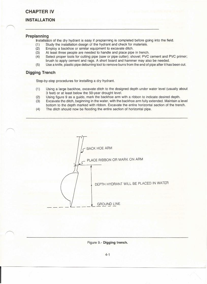
(1) Using a large backhoe, excavate ditch to the designed depth under water level (usually about3 feet) or at least below the 50-year drought level.
(2) Using figure 9 as a guide, mark the backhoe arm with a ribbon to indicate desired depth.(3) Excavate the ditch, beginning in the water, with the backhoe arm fully extended. Maintain a level
bottom to the depth marked with ribbon. Excavate the entire horizontal section of the trench.(4) The ditch should now be flooding the entire section of horizontal pipe.
BACK HOE ARM
PLACE RIBBON OR MARK ON ARM
DEPTH HYDRANT WILL BE PLACED IN WATER
GROUND LINE
Figure 9.- Digging trench.
4-1
I
Pipe Connections and Laying
Experience indicates that it is very important to follow instructions on cutting, connecting and fittingof pipes to prevent field failures. Special attention should be given to set time and cure time of cement(steps 10 and 11). ~
1. Cut pipe square to desired length using hand saw and miter box or mechanical cut off saw. (Be surecut is square and smooth).A tube cutter designed for plastic may also be used for cutting the pipe. (It is essential to removeraised bead left on outside of pipe).
2. Bevel the end of pipe to approximately 10 to 15 degrees.3. Clean and dry pipe and fitting socket of all dirt, moisture and grease. Use a clean, dry cloth.4. Check dry fit of pipe in fitting. Pipe should enter fitting socket about 1/3 to 3/4 inches deep.5. First dissolve inside socket surface by brushing with recommended primer. Be sure to use brush at
least one-half the size of pipe diameter. Use a scrubbing motion to assure penetration. Repeatedapplications may be necessary. More time is necessary for belled pipe sockets.
6. Next, dissolve surface of male end of pipe, to be inserted into socket, to depth of fitting socket bybrushing on liberal coat ~f primer. Be sure entire surface is well dissolved.
7. Again brush inside socket surface with primer, then without delay, apply proper cement liberally tomale end of pipe. The amount should be sufficient to fill any gap.Also apply cement inside of socket. Keep excess cement out of socket to prevent solvent damageto pipe. Time is important at this stage. APPLY A SECOND COAT OF CEMENT TO THE PIPE END.NOTE: The cement should be applied deliberately but without delay. It may be necessary for two peopleto work together when cementing larger size pipe and fittings.
8. While both the inside socket surface and the outside surface of the male end of the pipe are SOFTand WET with cement, push bottom of male end of the pipe in the socket, giving the male end aone-quarter (1/4) turn, if possible. THE PIPE MUST GO TO THE BOTTOM OF THE SOCKET. HOLDTHE JOINT TOGETHER UNTIL BOTH SOFT SURFACES ARE FIRMLY GRIPPED (USUALLY LESSTHAN 30 SECONDS).
9. After assembly, wipe excess cement from the pipe at the end of the fitting socket. A properly made r">.joint will normally show a bead around its entire perimeter. Any gaps at this point may indicate adefective assembly job, due to insufficient cement or the use of light bodied cement on large diameterswhere heavy bodied cement should have been used.
10. DO NOT DISTURB THE JOINT UNTIL INITIAL SET-UP OF THE CEMENT OCCURS!SET TIME: Handle the new assembled joints carefully until cement has gone through the set period.Recommended set time is related to temperature as follows:
30 minutes minimum at 60° F to 100°F1 hour minimum at 40° F to 60°F
2 hours minimum at 20° F to 40°F4 hours minimum at 0° F to 20°F
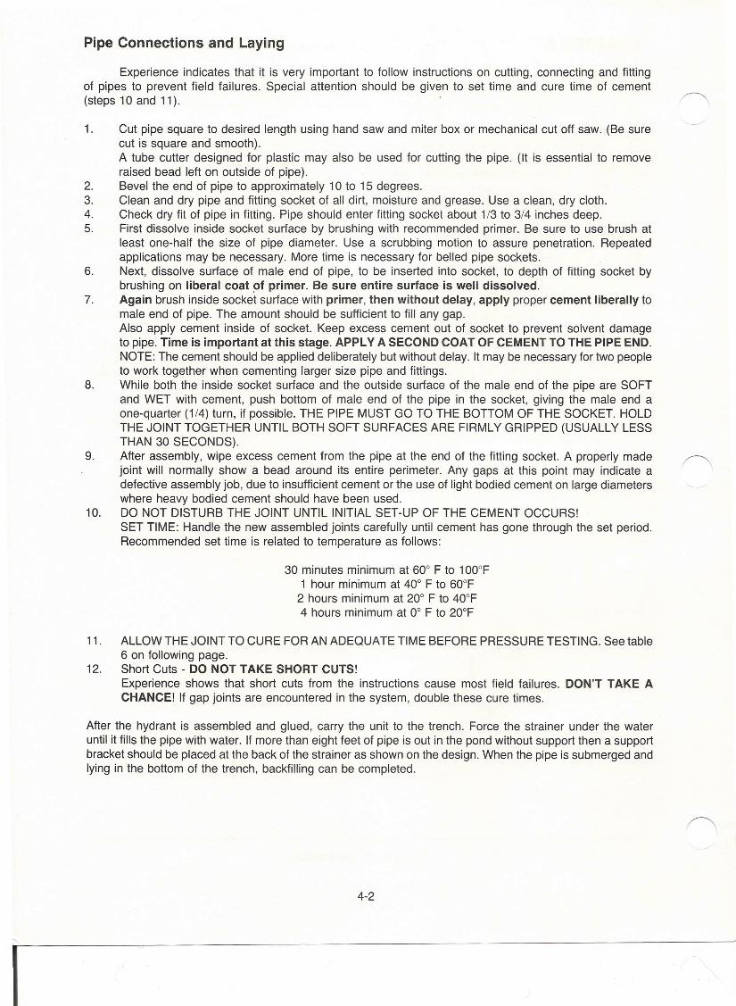
11. ALLOW THE JOINT TO CURE FOR AN ADEQUATE TIME BEFORE PRESSURE TESTING. See table6 on following page.
12. Short Cuts - DO NOT TAKE SHORT CUTS!Experience shows that short cuts from the instructions cause most field failures. DON'T TAKE ACHANCE! If gap joints are encountered in the system, double these cure times.
After the hydrant is assembled and glued, carry the unit to the trench. Force the strainer under the wateruntil it fills the pipe with water. If more than eight feet of pipe is out in the pond without support then a supportbracket should be placed at the back of the strainer as shown on the design. When the pipe is submerged andlying in the bottom of the trench, backfilling can be completed.
4-2
I
Table 6.- Joint cure time.
Test pressures for pipe sizes 3 1/2" to 6"
Temperature range duringcure period
Up to180 Ib/in2
Above 180to 315 Ib/in2
60° - 100°F40° - 60°F10° - 40°F
6 hr12. hr48 hr
24 hr48 hr8 days
Backfilling
After the pipe is firmly in place in the bottom of the ditch, place the backfill around the riser first andtamp so it is rigidly supported with earth fill. The ditch water is automatically forced back to the water sourceas backfilling is completed. Use caution to prevent large clumps or rocks from coming in contact with thepipe. Firmly pack the soil around pipe and continue until the original ground elevation is reached.
Smoothing and Revegetation
Smooth and rake all disturbed areas with a hand rake to prepare a seed bed. Apply grass seeds,fertilizer and mulch according to SCS specifications listed on table 7.
Table 7.- Seeding rates for ground covers.
Species Rate per Planting dates Fertilizer100ft2 M - Mountain rates per
P - Piedmont 1,000 ft2C - Coastal
Fescue and 1 Ib Aug-Oct - M 251bs.Rye Sept-Nov - P-C 6-12-12
Common 1/41b Mar-Jun - M-P 251bs.Bermuda Feb-Jun - C 6-12-12
Bahiagrass 1 Ib Mar-Jun - P 251bs.Oct-Jun - C 6-12-12
Oaylilly 111 tubers Jan-Oec - M-P-C 25 Ibstubers 12-24-21
4-3
I
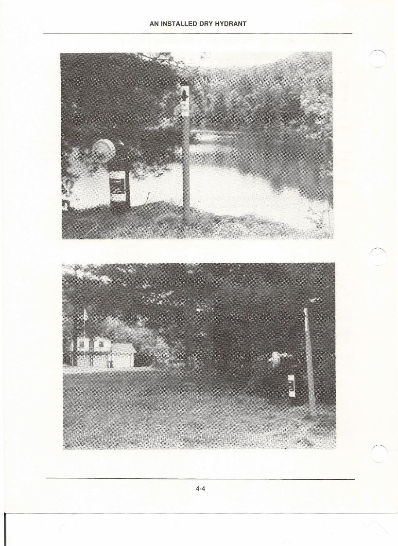
AN INSTALLED DRY HYDRANT
4-4
I
CHAPTER V
TESTING AND MAINTENANCE OF DRY HYDRANTS
qry hydrants require periodic checking, testing, and maintenance. This should be done semi-annually.Checking and testing by actual drafting should be a part of fire department training and drills. Thorough surveysshould reveal any deterioration in the water supply in ponds, streams, or cisterns.
Particular attention should be given to streams and ponds. Frequent cleaning may be needed toremove debris, dredging or excavation of silt, and protection from erosion. The hydrants should be tested atleast once a year with a pumper. Back flushing, followed by a pumper test at a maximum designed flow rate,with records kept of each test, is desired. Tests of this kind will not only verify proper condition but also keepthe line and strainer clear of silt and the water supply available for any fire emergency.
The pond should be free of aquatic growth. It may be necessary to drain the pond to control this growth.Consult with Cooperative Extension Service or USDA office for assistance in weed control.
Inspections should include safety procedures such as posting warning signs and seeing that life pre-servers, ropes, etc., are available. Give particular attention to local authority regulations governing such waterpoints.
It is important to consider appearance of this water point. Keep the grass trimmed and neat. Paint thehydrant periodically. The cap should be painted a reflective color to improve visibility during emergencies. Allidentification signs should be approved by the Department of Transportation prior to installation if they are tobe on the right of way or come under State laws.
Maintenance Record
These facilities require periodic checking, testing and maintenance semi-annually. Checking and testingby actual drafting should be a part of fire department training and drills. Thorough surveys should reveal anydeterioration in the water supply situation in ponds, streams or cisterns.
Give particular attention to streams and ponds. They may need frequent removal of debris, dredgingor excavation of silt and protection from erosion. Test the hydrants at least annually with a pumper. Backflushing, followed by a pumper test at a maximum designed flow rate, with records kept of each test, is highlydesirable. Tests of this kind will not only verify proper condition, but also keep the line and strainer clear ofsilt and water supply available for any fire emergency. Portions of the hydrant maintenance deal with on-siteconditions such as:
1. Locally required signs warning of penalties for tampering, destruction, etc. of the hydrant*2. Fire department hydrant identification sign*3. Inspection of roadway and surface4. Inspection of hydrant: condition, paint, riser, overall security, guard risers5. Grass cut (ensure that PVC has not been damaged by cutting machine).
A record of inspection should be maintained for each hydrant. See following page for suggested format.
'Check local and State DOT specific requirements concerning signs on rights-of-way.
5-1
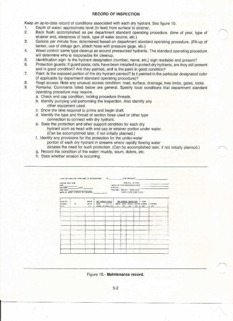
RECORD OF INSPECTION
Keep an up-to-date record of conditions associated with each dry hydrant. See figure 10.1. Depth of water: approximate level (in feet) from surface to strainer.2. Back flush: accomplished as per department standard operating procedure. (time of year, type of
strainer end, steepness of bank, type of water source, etc.)3. Gallons per minute flow: determined based on department standard operating procedure. (Fill-up of
tanker, use of deluge gun, attach hose with pressure gage, etc.)4. Weed control: same type cleanup as around pressurized hydrants. The standard operating procedure
will determine who is responsible for cleanup.5. Identification sign: Is the hydrant designation (number, name, etc,) sign readable and present?6. Protection guards: If guard posts, rails, have been installed to protect dry hydrants, are they still present
and in good condition? Are they painted, and is the paint in good condition?7. Paint: Is the exposed portion of the dry hydrant painted? Is it painted in the particular designated color
(if applicable by department standard operating procedure)?8. Head access: Note any unusual access condition: road, surface, drainage, tree limbs, gates, locks.9. Remarks: Comments listed below are general. Specify local conditions that department standard
operating procedure may require.a. Check end cap condition, locking procedure threads.b. Identify pumping unit performing the inspection. Also identify any
other equipment used.c. Show the time required to prime and begin draft.d. Identify the type and thread of section hose used or other type
connection to connect with dry hydrant.e. State the protection and other support condition for each dry
hydrant such as head with end cap or strainer portion under water.(Can be accomplished later, if not initially planned.)
f. Identify any provisions for the protection for the under-waterportion of each dry hydrant in streams where rapidly flowing waterdictates the need for such protection. (Can be accomplished later, if not initially planned.)
g. Record the condition of the water: muddy, scum, debris, etc.h. State whether erosion is occurring.
LOCATION/DIRECTION (POND/LAKE OR STREAM/RIVER) ___ DATE INSTALLED _
INITIAL TEST DATE
DATE _
OPM FLOW __ fLIPT
UNIT USED .-:-=-:=::-::::-:::-==DEPTH OF WATER (SURFACE TO STRAINER) _
TYPE/DIA. OF PIPE _
LENGTH OF rIPE UNDERGROUND/WATER _
FITTINGS -=--:c-::--==-::-:::-------STRAINER: END E.£. ~
INTAKE ~ ~ 01A/N
I I I I I IIDATE OF I I WATER DRY HYDRANT CHECK I DRY HYDRANT INSPECTION I ROAD I!INSPEC- I BY I DEPTH BACK ! G PM I WEEDS I SIGNI GUARDS I PAINT I ACCESS I REMARKS
ITION I (1) FLUSH (2j!FLOW (3)1 (4) I (5) I (6) 1(7) (B) (9)
I I I I II I I I II I I I II I I I II I I I II I I I II I I I II I I I II I I I II I I I II I I I II I I I II I I I II I I I II I I I II I I I II I I I II I I I II I I I II I I I I
Figure 10.- Maintenance record.
5-2
r
/
CHAPTER VI
USING THE DRY HYDRANT SYSTEM
In a water hauling operation, the time it takes to fill the tanker, the distance the tanker has to travel tothe fire and the time it takes to discharge the water from the tanker become critical elements in rural fireprotection. Time saved on anyone of the above points will increase the amount of water that can be hauledto the fire. Dry hydrants, properly located, can substantially reduce travel time from water source to fire.
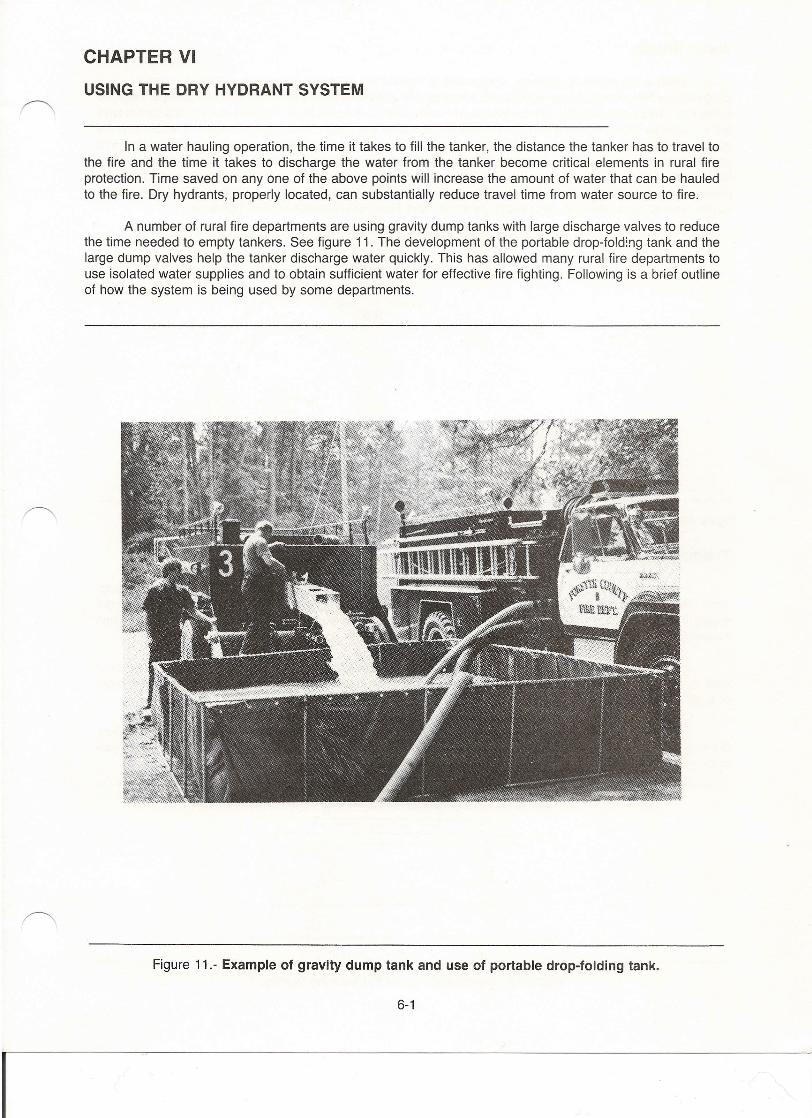
A number of rural fire departments are using gravity dump tanks with large discharge valves to reducethe time needed to empty tankers. See figure 11. The development of the portable drop-Ioldinq tank and thelarge dump valves help the tanker discharge water quickly. This has allowed many rural fire departments touse isolated water supplies and to obtain sufficient water for effective fire fighting. Following is a brief outlineof how the system is being used by some departments.
Figure 11.- Example of gravity dump tank and use of portable drop-folding tank.
6-1
I
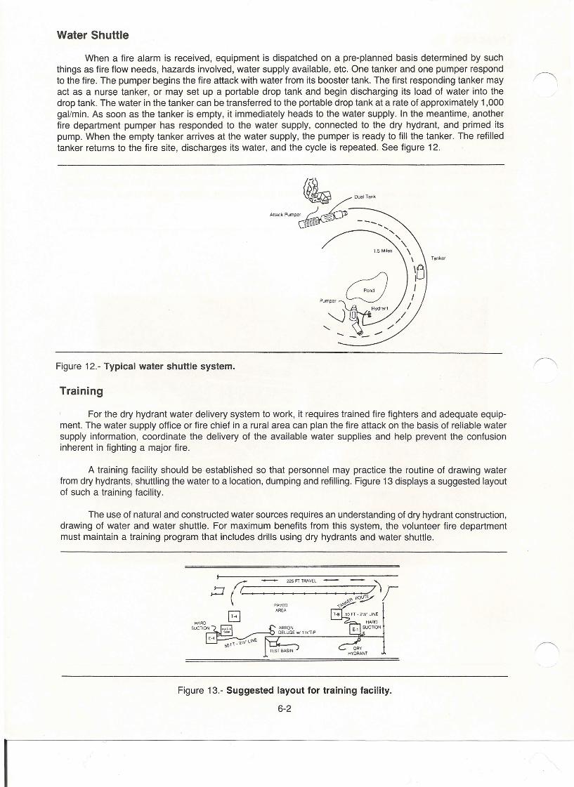
Water Shuttle
When a fire alarm is received, equipment is dispatched on a pre-planned basis determined by suchthings as fire flow needs, hazards involved, water supply available, etc. One tanker and one pumper respondto the fire. The pumper begins the fire attack with water from its booster tank. The first responding tanker mayact as a nurse tanker, or may set up a portable drop tank and begin discharging its load of water into thedrop tank. The water in the tanker can be transferred to the portable drop tank at a rate of approximately 1,000gal/min. As soon as the tanker is empty, it immediately heads to the water supply. In the meantime, anotherfire department pumper has responded to the water supply, connected to the dry hydrant, and primed itspump. When the empty tanker arrives at the water supply, the pumper is ready to fill the tanker. The refilledtanker returns to the fire site, discharges its water, and the cycle is repeated. See figure 12.
Tanker
Figure 12.- Typical water shuttle system.
Training
For the dry hydrant water delivery system to work, it requires trained fire fighters and adequate equip-ment. The water supply office or fire chief in a rural area can plan the fire attack on the basis of reliable watersupply information, coordinate the delivery of the available water supplies and help prevent the confusioninherent in fighting a major fire.
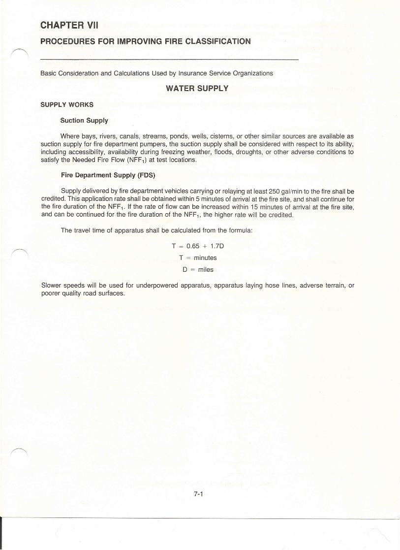
A training facility should be established so that personnel may practice the routine of drawing waterfrom dry hydrants, shuttling the water to a location, dumping and refilling. Figure 13 displays a suggested layoutof such a training facility.
The use of natural and constructed water sources requires an understanding of dry hydrant construction,drawing of water and water shuttle. For maximum benefits from this system, the volunteer fire departmentmust maintain a training program that includes drills using dry hydrants and water shuttle.
~ ('C 2_25_n_TAA_v_EL__ --- ---~~7)r·I'R07PAvED ,~yB AREA
DRYHYDRANT
Figure 13.- Suggested layout for training facility.
6-2
I
CHAPTER VII
PROCEDURES FOR IMPROVING FIRE CLASSIFICATION
Basic Consideration and Calculations Used by Insurance Service Organizations
WATER SUPPLY
SUPPLY WORKS
Suction Supply
Where bays, rivers, canals, streams, ponds, wells, cisterns, or other similar sources are available assuction supply for fire department pumpers, the suction supply shall be considered with respect to its ability,including accessibility, availability during freezing weather, floods, droughts, or other adverse conditions tosatisfy the Needed Fire Flow (NFF1) at test locations.
Fire Department Supply (FDS)
Supply delivered by fire department vehicles carrying or relaying at least 250 galimin to the fire shall becredited. This application rate shall be obtained within 5 minutes of arrival at the fire site, and shall continue forthe fire duration of the NFF1. If the rate of flow can be increased within 15 minutes of arrival at the fire site,and can be continued for the fire duration of the NFF1, the higher rate will be credited.
The travel time of apparatus shall be calculated from the formula:
T = 0.65 + 1.7D
T = minutes
D = miles
Slower speeds will be used for underpowered apparatus, apparatus laying hose lines, adverse terrain, orpoorer quality road surfaces.
7-1
I
The FDS shall be the capacity of the supply for the fire duration, the capacity of the source pumping equipment,the capacity of the delivery equipment, whichever is least, at the test location, expressed in gal/min.
Hydrant Distribution
A cistern or other suction point must be capable of supplying 250 gal/min for at least 2 hours to be recog-nized.
Hydrant Size, Type and Installation
Prorate points according to the number of hydrants of each type compared with the total number ofhydrants.
Cistern or suction point 25
Inspection and Condition of Hydrants
A. Inspection
The frequency of inspection is the average time interval between the three most recent inspections.
Frequency of Inspections Points
1/2 year1 year2 years3 years4 years5 years or more
1008065554540
Note 1: The points for inspection frequency shall be reduced by 10 points if the inspections areincomplete.
If the inspection of cisterns or suction points does not include actual drafting with apumper, deduct 40 points.
Note 2: If there are no records of claimed inspections, deduct an additional 20 points.
7-2
I

B. Condition(HF)
Prorate a factor (HF) from the following list of conditions according to the actual condition of hydrantsexamined compared with the total number examined during the survey:
Condition Factor
Standard (no leaks, opens easily, con-spicuous, well located for use by pumper) 1.0
Usable 0.5
Not Usable 0.0
7-3
I
CHAPTER VIII
MATERIALS
Materials for dry hydrants may be obtained by contacting your local RC&D Council. Be sure to installhigh quality material. The Southeastern Association of RC&D Councils can help you secure quality products.Schedule 40 PVC dry hydrant materials are being used in many areas.
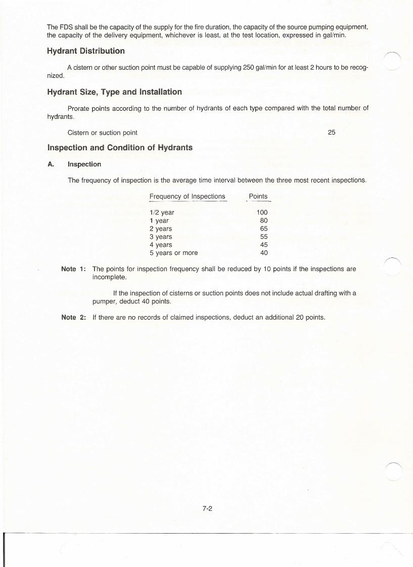
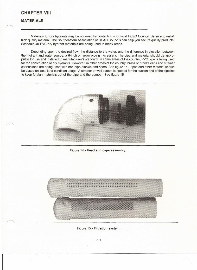
Depending upon the desired flow, the distance to the water, and the difference in elevation betweenthe hydrant and water source, a 6-inch or larger pipe is necessary. The pipe and material should be appro-priate for use and installed to manufacturer's standard. In some areas of the country, PVC pipe is being usedfor the construction of dry hydrants. However, in other areas of the country, brass or bronze caps and strainerconnections are being used with iron pipe elbows and risers. See figure 14. Pipes and other material shouldbe based on local land condition usage. A strainer or weli screen is needed for the suction end of the pipelineto keep foreign materials out of the pipe and the pumper. See figure 15.
Figure 14.- Head and caps assemblv.
Figure 15.- Filtration system.
8-1
I
CHAPTER IXSOURCES OF ASSISTANCE
Financial
Most rural fire departments are volunteer and funded by public monies. Lack of funding is a majorreason for the limited number of dry hydrants. Many RC&D councils across the country have adopted dryhydrants as a project to assist with local communities. An RC&D council is a non-profit, incorporated councilof community leaders working to assist in the conservation, development and improvement of naturalresources.
In some States, funds are available to all counties. These funds are made possible through the RC&Dcouncils, your State's Office of Energy, Soil and Water Conservation Commission, and forestry agency. Forthe nearest RC&D council, contact the USDA's SCS Office, Washington DC 20250, or telephone (202)475-4575. Additional information is available from the Fire and Aviation Staff of the Forest Service's SouthernRegion; telephone (404) 347-4243. The district offices of the Farmers Home Administration offer a brochure,Community Facility Loans, Program Aid No. 1100.
Technical Assistance
Assistance with the survey, design and 50-year drought calculations may be available from your localSCS engineer, professional engineering association, or State forestry agency. For assistance with developinga Master Fire Plan to include dry hydrants, contact your state RFD coordinator or State forestry agency.
Fire Insurance Classification
Most States use ISO Commercial Risk Service, Inc. classification in the calculation of property insurancepremiums. In order to be recognized as Class 8 or better, the fire department must be able to deliver at least250 gallons of water per minute throughout the area within 5 minutes of the arrival of the first apparatus, andmaintain at least that rate of flow without interruption for a 2-hour period. A local fire district/county/city interestedin reclassification will be asked to provide the following information.
A. Criteria concerning water delivery by fire department apparatus:
1. When a tanker relay system is used, the volume of the tanker capacity is reduced by 10 percentfor spillage, underfilling and incomplete unloading.
2. Travel time of apparatus is calculated from the formula:T = 0.65 + 1.7D
T = minutesD = miles.
Slower speeds will be used for low-powered apparatus, adverse terrain, nonpaved roads, orapparatus laying hose lines.
3. The delivery rate of a tanker relay system will be affected by the filling and dumping rate of thetankers and the usable volume of the fire-site holding tanks or other fire-site storage.
4. Credit may be given for apparatus responding from outside the community, depending uponcommunication facilities, handling of alarms, interdepartmental training, fire ground communica-tions and arrival times at fires.
9-1
I
B. A map showing: NFPA1231, Par. B.1.2.7:1. Boundary of the community or area served by the local fire department.2. All roads usable by fire apparatus under all-weather conditions, certified by county engineer, or
other registered professional engineer.3. Bridges that do not have a safe-weight capacity sufficient for fire fighting apparatus. Note: Weight
information is available from your State Department of Transportation.4. The locations of fire stations.5. The locations and names of fire stations housing automatic-aid apparatus.6. The locations and identification of water supply points (hydrants or suction supplies).7. The total paved and unpaved road mileage (State, county, city and town) within the area served
by the fire department.C. A description of each water supply point; and:
1. The maximum rate for a hydrant supplied from a water main, or a dry hydrant, using the pumperand hose arrangement scheduled to be used at this hydrant (supported by test results). Note: Themaximum rate if tankers are supplied directly from a hydrant, using the hose arrangementscheduled to be used at this hydrant (supported by test results).
2. For an impounded supply, cistern, tank or other storage facility show the minimum storageavailable (at not over 15-foot lift) during a drought with an average 50-year frequency (certified bya registered professional engineer). The maximum rate obtainable using the pumper(s) andhose arrangement scheduled to be used at this point (supported by test results).
3. For a supply from a flowing stream, the minimum rate of flow available (not over 15-foot lift)during a drought with an average 50-year frequency (certified by a registered professionalengineer, hydrologist, geologist, soil conservationist, or Federal surface water specialist.) Themaximum rate obtainable using the pumper(s) and hose arrangement scheduled to be used atthis point (supported by test results).
4. For each location, the number of pumpers that can operate simultaneously.5. For each water supply point, the distance to the water supply point from each fire station with
responding apparatus.6. A statement, signed by the owner of any private suction water supply point, authorizing its use
by the fire department.D. A description of a recent fire or demonstration, more than 1,000 feet from a hydrant, where 250 gallons
of water per minute or more were delivered for more than 1 hour, with the following information:1. Location of fire or test2. Date3. Number of tankers (if used) dumping simultaneously4. Rate of flow delivered5. Distance delivered6. Time duration7. Number of personnel participating, with a description of each person's function such as fire
fighter, pump operator, tanker operator, etc.8. The apparatus used with the following information for each:
a. Nameb. Pump capacityc. Tank capacityd. Functions
9. The holding tanks used, if any, with the following information for each:a. Total capacityb. Usable capacity which is the total capacity less volume that cannot be pumped out when
drawing from the tank.c. Set-up timed. Name of apparatus carrying each holding tank.
10. Description of the overall operation.E. If different combinations of apparatus are used in various sections of the city, list the combinations with
the data in numbers 7 and 8 above, and show the areas on the map.F. For each vehicle used to carry water, indicate the actual time to discharge the capacity of the tank and
the actual time necessary to fill the tank using the pumpers that normally will be used for filling. If differentcapacity pumpers will be used for filling, the time shall be obtained for filling with each capacity pumper.(Note: The actual time to be recorded shall be the time necessary for the vehicle to travel 200 feet to thesite, maneuver into position, fill or dump and travel 200 feet from the site.)
9-2
I
G. When the water supply is delivered through a hose line, indicate the time for a pumper to travel 200feet to a water supply point, connect suction and discharge hoses and commence pumping. If thewater supply points are both hydrants and drafting sites, the time shall be obtained for both types ofwater supply points.
H. When the water supply is delivered through a hose line, indicate the lengths and diameter of the hoseline used for the time trial and the time when the pumper begins to fill the hose line until a solid streamof water is delivered at the other end.
I. List the current equipment inventories for all apparatus in service and in reserve in the city. Copies ofthe form, APPARATUS AND EQUIPMENT, are located in the appendix.
J. When the use of a water supply point at times depends on creating an opening in ice, the maximumknown thickness of ice shall be given. Include a statement explaining the equipment used, apparatuscarrying the equipment and the estimated time needed to provide a drawing site to draw water whenthe ice is at the maximum thickness.
Suggested Reading
Davis, Larry. 1989. Rural Fire Fighting Operations; 370 pages. Available from International Society of FireService Instructors, 30 Main St., Ashland, MA 01721; telephone (508) 881-5800.
National Fire Protection Association. 1989. NFPA Standard 1231, Water Supplies for Suburban and RuralFire Fighting; 40 pages. A new edition will be published in September 1993. Available from NFPA,1 Battery March Park, Quincy, MA 02269: telephone 1-800-344-3555.
U.S. Department of Agriculture, Farmers Home Administration. Community Facility Loans. Program Aid No.1100. Available from district offices of the FHA.
Your local library may offer more sources.
Technical Consultation
For more information on the Dry Hydrant Program and information on successful rural communitiesnow using dry hydrants for improved fire protection, you may contact any of the following.
Jerry L. BolingRC&D Coordinator624 Green St., N.E.Gainesville, GA 30501
Don FreyerRFD CoordinatorGA Forestry CommissionP.O. Box 819Macon, GA 31298-4599
Don TomczakCooperative ForestryForest Service1720 Peachtree Road N.W.Atlanta, GA 30367-9102
Freddie WilliamsSoil Conservation ServiceP.O. Box 13Athens, GA 30601
George BrooksFire & Aviation ManagementForest Service1720 Peachtree Road N.W.Atlanta, GA 30367-9102
9-3
I
CHAPTER X
APPENDIX
Reference Information
Design form for pond
Design form for stream
Information sheet for fire department capability
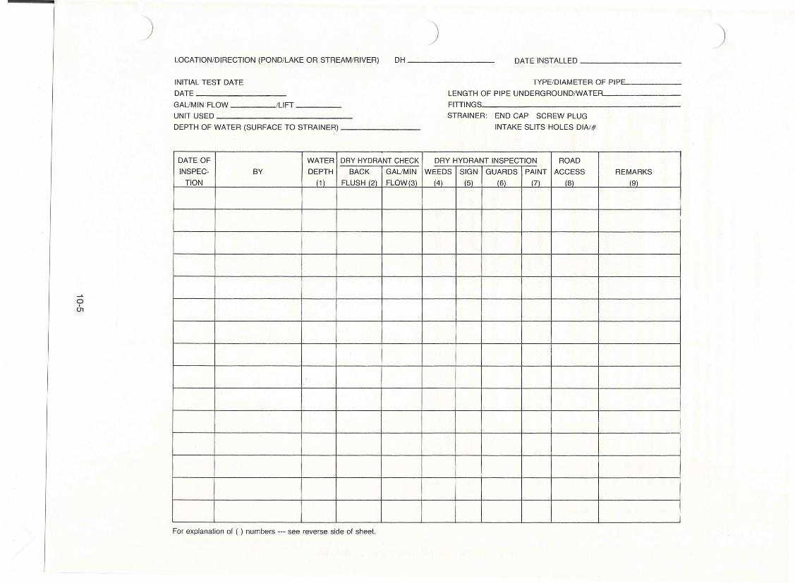
Dry hydrant location and initial test data sheet
Record of Inspection
Water source survey sheet
Design survey data sheet
ISO classification rate and estimated premiums
Dry hydrant maintenance record
Water usage agreement/authorization form
Fire department's water shuttle calculation and record
10-1
I
)_L CONSfRV ••.TION Sf:RVICf
) )
0, [
r\8"~
·f);"PfPY< ,0,1>< r().f),P'pe'" R."•• J.~in~ ~c,.w
Crill/Ie
SECTION A·At;rQunq "n.
Q
•• SIr.a,m7~jl~
o/" W,nyr t,new~ ~I'~., ~ rA<V ,q>
l'f'iIJ !j n PII'II"ll"illlllfl'JJ1DI 'lll~ I II ! 1 I !1~l 1 1 11 1 •I\'I~[ -®- Iv 23"""""'--,f~r---l ,.....,........•....••.."'"'---J J'.(.
• A-111'4"9
hel I
PIPE DETAILS
BILL OF MATERIALSHE..- I "'ARK OU.lN I UNIT
e: TDS"lIydr",,1 A,,#m~/'r ~O'lJe'J(/1 I / Itoch
Hy"ronl co-s: I 2 / lEach.-.J!.j. ~VCStrainer I ~ I IEoC'h
,. se». «a pVC SO' l3.nc' I 4 J LEach,. xh:- 40 PVCp7p-, -Ris,r I 6 m.Fre: .seA «o PVC PiP4 I , li".Fte:5"". 40 PVC Coupl/nos I 7 Eoch'IInd,rwolu .jvpp.orl Crodle I 8 I IEeenStra/",r Cop I 3 I IEDen,- se». 40 PVC -'''$. lJ.nd I /0 I lEach.6/". Con ,
ConC/,oner
QUANTITIESaUAN I UNITTElA
Slr.um II," W,O'fh ;'., I
jlreom Flow Depfh F •• , t
Avcraoe Flow G.P./rl.!
Mo.rimvm Or014/ From WIt.
PIPELINE PLAN
aW
It PIPELINE PROFILE
DETAILED HYDRANT LOCATION GENERAL LOCATION MAP
- . ~•... _ ..---_ •.............
Nol., Tlus li""9n IJ Apl'l,i:,,/)/, Only 1 . '===--===:.:::=:With SI"gtn 0/ AtI,vvgl, [).plhAnd ,-_ -Flow. '-- .•••. ' _to.~ ...- . .,
STREAM· DRY HYDRANTNO. __
___ COUNTY, GeORGIA
PROFILES & LOCATION MAP
1\ U. S. DEPARTMENT OF AGRICULTURE;OW SOIL CONSERVATION SERVICE '
" •••O".OO ••.• lNQ GA-.·nt
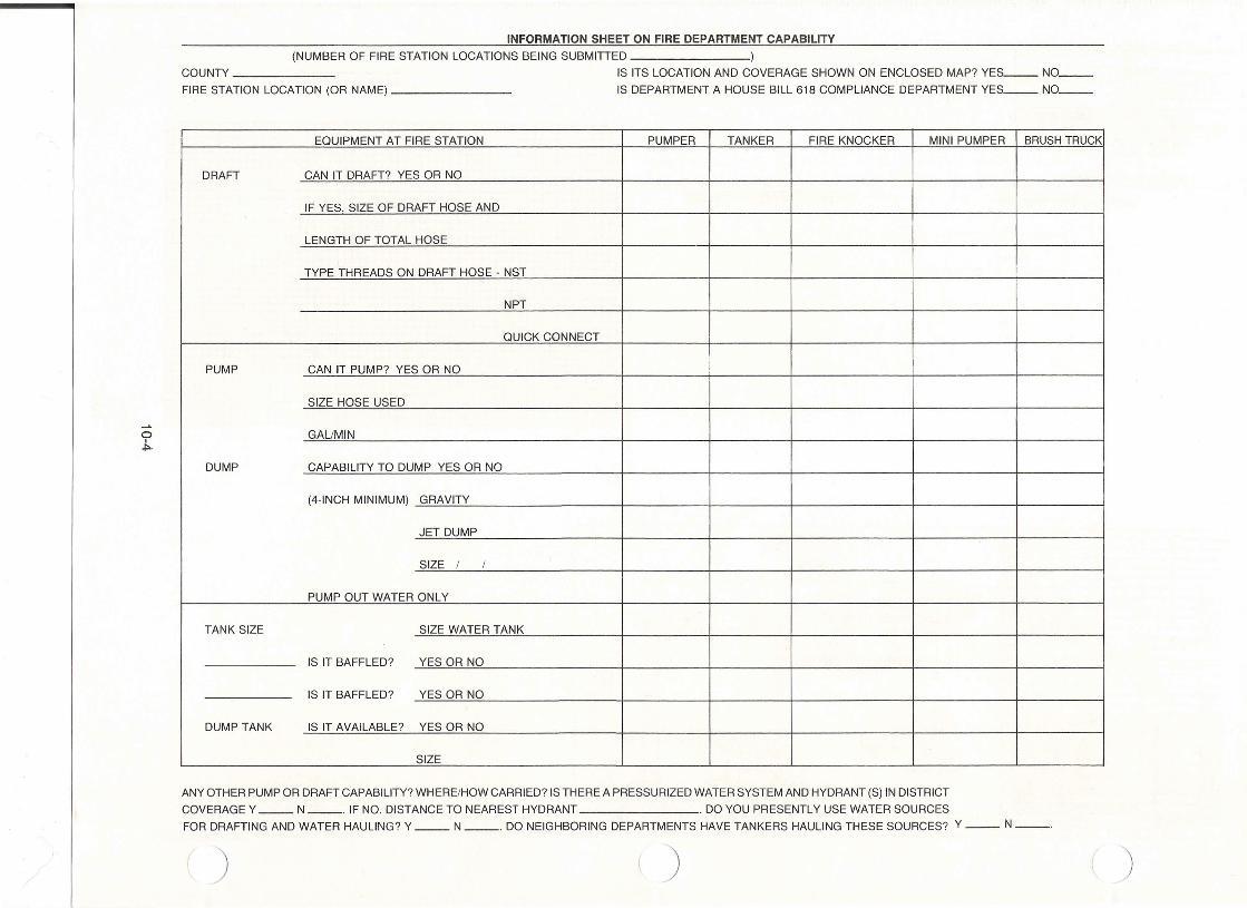
INFORMATION SHEET ON FIRE DEPARTMENT CAPABILITY(NUMBER OF FIRE STATION LOCATIONS BEING SUBMITTED )
IS ITS LOCATION AND COVERAGE SHOWN ON ENCLOSED MAP? YES__ NO__IS DEPARTMENT A HOUSE BILL 618 COMPLIANCE DEPARTMENT YES__ NO__
COUNTY _
FIRE STATION LOCATION (OR NAME) _
o.;,.
EQUIPMENT AT FIRE STATION PUMPER TANKER FIRE KNOCKER MINI PUMPER BRUSH TRUCK
DRAFT CAN IT DRAFT? YES OR NO
IF YES SIZE OF DRAFT HOSE AND
LENGTH OF TOTAL HOSE
TYPE THREADS ON DRAFT HOSE - NST
NPT
QUICK CONNECT
PUMP CAN IT PUMP? YES OR NO i
SIZE HOSE USED
GALIMIN
DUMP CAPABILITY TO DUMP YES OR NO
(4-INCH MINIMUM) GRAVITY
JET DUMP
SIZE / /
PUMP OUT WATER ONLY
TANK SIZE SIZE WATER TANK
IS IT BAFFLED? YES OR NO
IS IT BAFFLED? YES OR NO
DUMP TANK IS IT AVAILABLE? YES OR NO
SIZE
ANY OTHER PUMP OR DRAFT CAPABILITY? WHERE/HOW CARRIED? IS THERE A PRESSURIZED WATER SYSTEM AND HYDRANT (S) IN DISTRICTCOVERAGE Y __ N __ . IF NO. DISTANCE TO NEAREST HYDRANT . DO YOU PRESENTLY USE WATER SOURCESFOR DRAFTING AND WATER HAULING? Y __ N __ . DO NEIGHBORING DEPARTMENTS HAVE TANKERS HAULING THESE SOURCES? Y __ N --.
) )
o0,
) ) )LOCATION/DIRECTION (POND/LAKE OR STREAM/RIVER)
DH _DATE INSTALLED _
INITIAL TEST DATEDATE _
GAUMIN FLOW /LiFT _UNIT USED _
DEPTH OF WATER (SURFACE TO STRAINER) _
TYPE/DIAMETER OF PIPc.E _
LENGTH OF PIPE UNDERGROUNDIWATER~ _FITTINGS, _
STRAINER: END CAP SCREW PLUG
INTAKE SLITS HOLES DIAI#
DATE OF WATER DRY HYDRANT CHECK DRY HYDRANT INSPECTION ROADINSPEC- BY DEPTH BACK GAUMIN WEEDS SIGN GUARDS PAINT ACCESS REMARKS
TION (1) FLUSH (2) FLOW(3) (4) (5) (6) (7) (8) (9)
For explanation of ( ) numbers --- see reverse side of sheet.
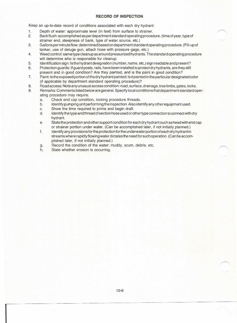
RECORD OF INSPECTION
Keep an up-to-date record of conditions associated with each dry hydrant:
1. Depth of water: approximate level (in feet) from surface to strainer.2. Back flush: accomplished as per department standard operating procedure. (time of year, type of
strainer end, steepness of bank, type of water source, etc.)3. Gallons per minute flow: determined based on department standard operating procedure. (Fill-up of
tanker, use of deluge gun, attach hose with pressure gage, etc.)4. Weed control: same type cleanup as around pressurized hydrants. The standard operating procedure
will determine who is responsible for cleanup.5. Identification sign: Isthe hydrant designation (number, name, etc,) sign readable and present?6. Protection guards: If guard posts, rails, have been installed to protect dry hydrants, are they still
present and in good condition? Are they painted, and is the paint in good condition?7. Paint: Is the exposed portion ofthe dry hydrant painted: Is it painted in the particular designated color
(if applicable by department standard operating procedure)?8. Road access: Note any unusual access condition: road, surface, drainage, tree limbs, gates, locks.9. Remarks: Comments listed below are general. Specify local conditions that department standard oper-
ating procedure may require.a. Check end cap condition, locking procedure threads.b. Identify pumping unit performing the inspection. Also identify any other equipment used.c. Show the time required to prime and begin draft.d. Identify the type and thread of section hose used or othertype connection to connect with dry
hydrant.e. State the protection and other support condition for each dry hydrant such as head with end cap
or strainer portion under water. (Can be accomplished later, if not initially planned.)f. Identify any provisions forthe protection forthe underwater portion of each dry hydrant in
streams where rapidly flowing water dictates the need for such operation. (Can be accom-plished later, if not initially planned.)
g. Record the condition of the water: muddy, scum, debris, etc.h. State whether erosion is occurring.
10-6
I
) ) )
WATER SOURCE SURVEY
___________ FIRE DEPARTMENT
1, Road name, 2, Type 3, Distance 4, Water 5, Size 6, Access road 7, Owner 8, Permit g, Comments
I10, Rating
number source trornaccess lift Surfaceownershipturn-around obtained
P L S No, Feet Ft. Ac-w H G 0 S C P Y N Name ? Y N 1 2 3 4
oI--J INSTRUCTIONS:
1, Road name/number: Official name/number from county map,
2, Typesource: P (pond), L (lake), S (any flowing water- river, stream,
etc.)
3. Distance: From end of access road to water source.
4, Water Lift- ft: Estimated feet from surface of lake to ground at pro-posed hydrant.
5, Size of water sou rce: Lakes (est. su rface acres), stream (est. width
and depth)
6, Access road: 'Surface: H (hard), G (gravel), 0 (dirt - not ISO Class'
acceptable)
7, Owner: Name of owner of water source and access road,
8, Permit obtained: Can a permit be obtained if needed?
Y (yes) N (no) ? (don't know)
g, Comments: Explanations needed and not covered previously, Forexample,
"need gravel grading"; "power line on pole relocation" or "gates" ,
10. Rating: Overall county-wide rating by Firefighters' Association
NOTE:
1, Install or improve now,
2, Good source, but use after all #1's are installed,
3, Probably not a good source; use only if more sources are necessary,
4, Do not use; too much improvement needed. Include these so that a
record exists that the source was inventoried,
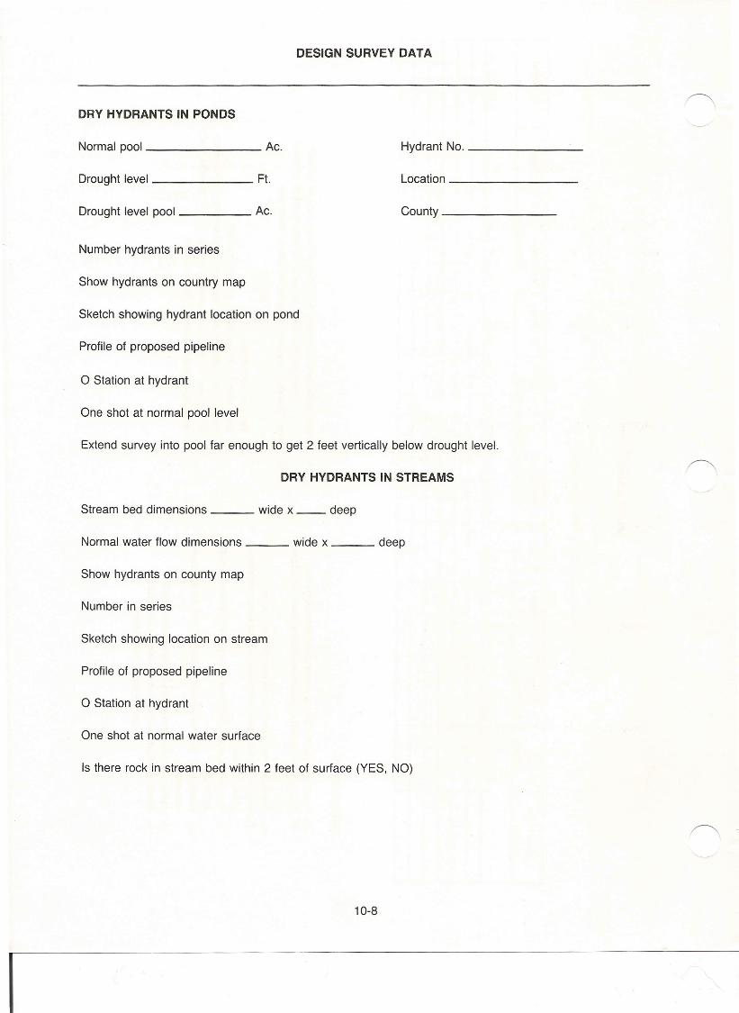
DESIGN SURVEY DATA
DRY HYDRANTS IN PONDS
Normal pool Ac.
Drought level Ft.
Drought level pool Ac.
Hydrant No. _
Location _
County _
Number hydrants in series
Show hydrants on country map
Sketch showing hydrant location on pond
Profile of proposed pipeline
o Station at hydrant
One shot at normal pool level
Extend survey into pool far enough to get 2 feet vertically below drought level.
DRY HYDRANTS IN STREAMS
Stream bed dimensions wide x __ deep
Normal water flow dimensions wide x deep
Show hydrants on county map
Number in series
Sketch showing location on stream
Profile of proposed pipeline
o Station at hydrant
One shot at normal water surface
Is there rock in stream bed within 2 feet of surface (YES, NO)
10-8
I
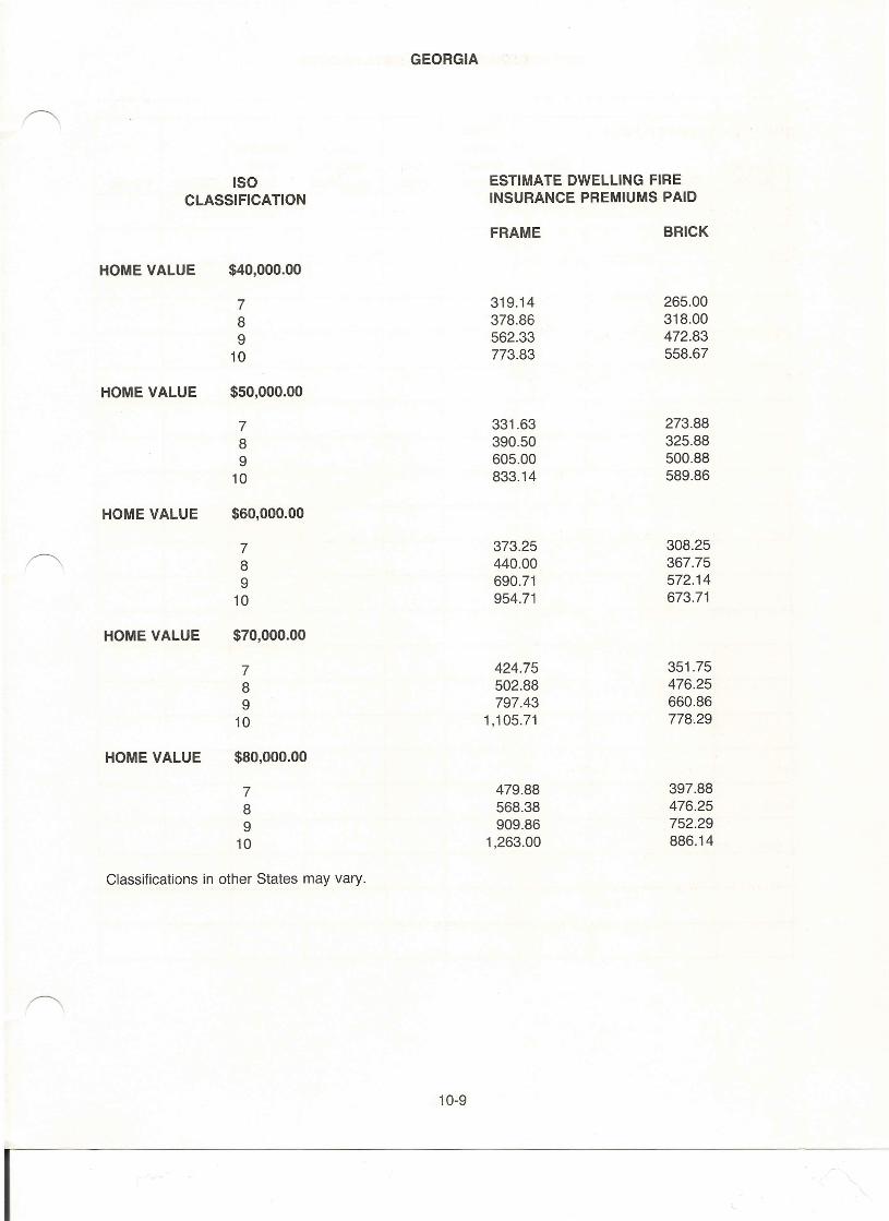
GEORGIA
ISO ESTIMATE DWELLING FIRECLASSIFICATION INSURANCE PREMIUMS PAID
FRAME BRICK
HOME VALUE $40,000.00
7 319.14 265.008 378.86 318.009 562.33 472.83
10 773.83 558.67
HOME VALUE $50,000.00
7 331.63 273.888 390.50 325.889 605.00 500.88
10 833.14 589.86
HOME VALUE $60,000.00
7 373.25 308.258 440.00 367.759 690.71 572.14
10 954.71 673.71
HOME VALUE $70,000.00
7 424.75 351.758 502.88 476.259 797.43 660.86
10 1,105.71 778.29
HOME VALUE $80,000.00
7 479.88 397.888 568.38 476.259 909.86 752.29
10 1,263.00 886.14
Classifications in other States may vary.
10-9
I

DRY HYDRANT MAINTENANCE RECORD
Pumpwater Check Perform
Hydrant Clean through Cut security draftNumber Date Location strainer pipes grass of system test Gal/min Initials
10-10
I

WATER USAGE AGREEMENT
TO: _
County
FROM: _
Property Owner
SUBJECT: Letter of authorization to develop and utilize water source on my property.
The County is hereby authorized to develop a refill site at ___________________________ for the purpose of providing water to extinguish fires in my communityand for other uses with my permission.
I further give the County permission to erect a dry hydrant stand at this location.I understand that County will erect the stand and providematerials.
The County will complete all excavation work so that the surrounding areas andthe surface of the ground will be smooth, and present a pleasing appearance.
The County may use, test, the dry hydrant at any time they deem necessaryfor continuity of hydrant operations.
The complete operation of the dry hydrant stand has been explained and all facets of the installation havebeen explained and I fully concur with all parts of the operation.
Permission is hereby granted to County to come upon my land to refill itstankers until I revoke this permission in writing to County.
SIGNATURE OF LAND OWNER
I have advised the land owner of the purpose, type of stand, method of operation with the above factsexplained.
SIGNATURE OF COUNTY REPRESENTATIVE
10-11
I
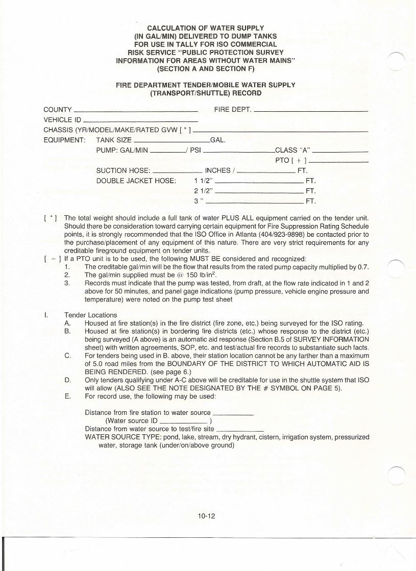
CALCULATION OF WATER SUPPLY(IN GALIMIN) DELIVERED TO DUMP TANKSFOR USE IN TALLY FOR ISO COMMERCIAL
RISK SERVICE "PUBLIC PROTECTION SURVEYINFORMATION FOR AREAS WITHOUT WATER MAINS"
(SECTION A AND SECTION F)
FIRE DEPARTMENT TENDER/MOBILE WATER SUPPLY(TRANSPORT/SHUTTLE) RECORD
COUNTY FIRE DEPT. _VEHICLE ID _
CHASSIS (YR/MODEUMAKE/RATED GVW [ * 1------------------EQUIPMENT: TANK SIZE GAL.
PUMP: GAUMIN / PSI CLASS "A" _
PTO [ + 1------SUCTION HOSE: INCHES / FT.
DOUBLE JACKET HOSE: 1 1/2" FT.2 1/2" FT.3" FT.
[ * 1 The total weight should include a full tank of water PLUS ALL equipment carried on the tender unit.Should there be consideration toward carrying certain equipment for Fire Suppression Rating Schedulepoints, it is strongly recommended that the ISO Office in Atlanta (404/923-9898) be contacted prior tothe purchase/placement of any equipment of this nature. There are very strict requirements for anycreditable fireground equipment on tender units.
+ 1 If a PTO unit is to be used, the following MUST BE considered and recognized:1. The creditable gal/min will be the flow that results from the rated pump capacity multiplied by 0.7.2. The gal/min supplied must be @ 150 lb/in",3. Records must indicate that the pump was tested, from draft, at the flow rate indicated in 1 and 2
above for 50 minutes, and panel gage indications (pump pressure, vehicle engine pressure andtemperature) were noted on the pump test sheet
I. Tender LocationsA. Housed at fire station(s) in the fire district (fire zone, etc.) being surveyed for the ISO rating.B. Housed at fire station(s) in bordering fire districts (etc.) whose response to the district (etc.)
being surveyed (A above) is an automatic aid response (Section B.5 of SURVEY INFORMATIONsheet) with written agreements, SOP, etc. and test/actual fire records to substantiate such facts.
C. For tenders being used in B. above, their station location cannot be any farther than a maximumof 5.0 road miles from the BOUNDARY OF THE DISTRICT TO WHICH AUTOMATIC AID ISBEING RENDERED. (see page 6.)
D. Only tenders qualifying under A-C above will be creditable for use in the shuttle system that ISOwill allow (ALSO SEE THE NOTE DESIGNATED BY THE # SYMBOL ON PAGE 5).
E. For record use, the following may be used:
Distance from fire station to water source _(Water source 10 )
Distance from water source to test/fire site _WATER SOURCE TYPE: pond, lake, stream, dry hydrant, cistern, irrigation system, pressurized
water, storage tank (under/on/above ground)
10-12
I
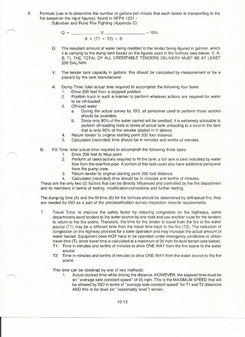
II. Formula (use is to determine the number of gallons per minute that each tanker is transporting to thefire based on the input figures): found in NFPA 1231 -
Suburban and Rural Fire Fighting (Appendix C)
Q = V - 10%
A + (T1 + T2) + B
Q: The resultant amount of water being credited to the tender being figured in gal/min, whichit is carrying to the dump tank based on the figures used in the formula (see below- V, A,B, T). THE TOTAL OF ALL CREDITABLE TENDERS DELIVERY MUST BE AT LEAST250 GAL/MIN.
V: The tender tank capacity in gallons: this should be calculated by measurement or be aplacard by the tank manufacturer
A: Dump Time: total actual time required to accomplish the following four tasks1. Drive 200 feet from a stopped position.2. Position truck in such a manner to perform whatever actions are required for water
to be off-loaded.3. Off-load water
a. During the actual survey by ISO, all personnel used to perform these actionsshould be available.
b. Since only 90% of the water carried will be credited, it is extremely advisable toperform off-loading tests in terms of actual tank unloading to a level in the tankthat is only 90% of the volume (stated in V above).
4. Return tender to original starting point 200 foot distance.5. Calculated (recorded) time should be in minutes and tenths of minutes.
B: Fill Time: total actual time required to accomplish the following three tasks.1. Drive 200 feet to fillup point.2. Perform all tasks/actions required to fill the tank; a full tank is best indicated by water
flow from the overflow pipe. A portion of this task could also have additional personnelfrom the pump crew.
3. Return tender to original starting point 200 foot distance.4. Calculated (recorded) time should be in minutes and tenths of minutes.
These are the only two (2) factors that can be directly influenced and controlled by the fire departmentand its members in terms of testing, modification/corrections and further testing.
The dumping time (A) and the fill time (B) for the formula should be determined by drill/actual fire; theyare needed by ISO as a part of the preclassification survey inspection records requirements.
T: Travel Time: to improve the safety factor by reducing congestion on the highways, somedepartments send tenders to the water source by one road and use another route for the tendersto return to the fire scene. Therefore, the time for the tender to travel from the fire to the watersource (T1) may be a different time than the travel time back to the fire (T2). The reduction ofcongestion on the highway provides for a safer operation and may increase the actual amount ofwater hauled. Equipment does NOT have to be operated under emergency conditions to obtaintravel time (T), since travel time is calculated at a maximum of 35 mph for level terrain (see below).T1: Time in minutes and tenths of minutes to drive ONE WAY from the fire scene to the water
source.T2: Time in minutes and tenths of minutes to drive ONE WAY from the water source to the fire
scene.
This time can be obtained by one of two methods:1. Actual clocked time while driving the distance. HOWEVER, the elapsed time must be
an "average safe constant speed" of 35 mph. This is the MAXIMUM SPEED that willbe allowed by ISO in terms of "average safe constant speed" for T1 and T2 distancesAND this is for level (or "reasonably level") terrain.
10-13
I
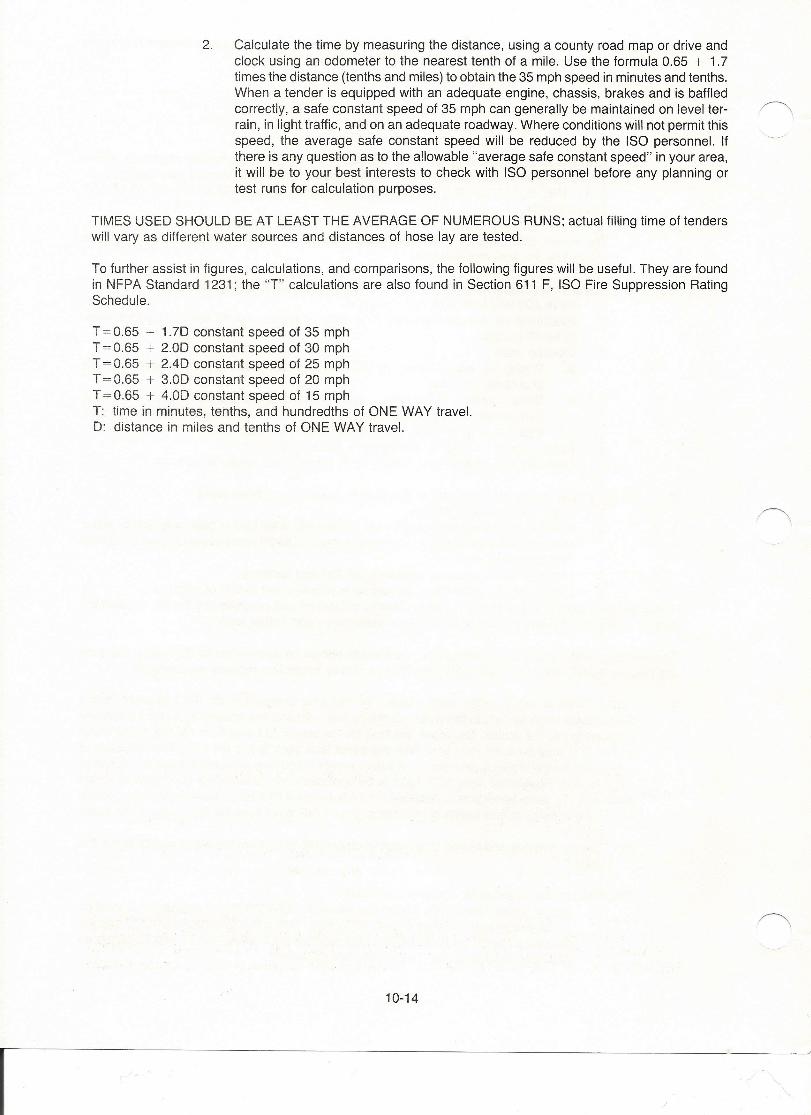
2. Calculate the time by measuring the distance, using a county road map or drive andclock using an odometer to the nearest tenth of a mile. Use the formula 0.65 + 1.7times the distance (tenths and miles) to obtain the 35 mph speed in minutes and tenths.When a tender is equipped with an adequate engine, chassis, brakes and is baffledcorrectly, a safe constant speed of 35 mph can generally be maintained on level ter-rain, in light traffic, and on an adequate roadway. Where conditions will not permit thisspeed, the average safe constant speed will be reduced by the ISO personnel. Ifthere is any question as to the allowable "average safe constant speed" in your area,it will be to your best interests to check with ISO personnel before any planning ortest runs for calculation purposes.
TIMES USED SHOULD BE AT LEAST THE AVERAGE OF NUMEROUS RUNS; actual filling time of tenderswill vary as different water sources and distances of hose lay are tested.
To further assist in figures, calculations, and comparisons, the following figures will be useful. They are foundin NFPA Standard 1231; the "T" calculations are also found in Section 611 F, ISO Fire Suppression RatingSchedule.
T=0.65 + 1.7D constant speed of 35 mphT = 0.65 + 2.0D constant speed of 30 mphT = 0.65 + 2.4D constant speed of 25 mphT = 0.65 + 3.0D constant speed of 20 mphT = 0.65 + 4.0D constant speed of 15 mphT: time in minutes, tenths, and hundredths of ONE WAY travel.D: distance in miles and tenths of ONE WAY travel.
10-14
I
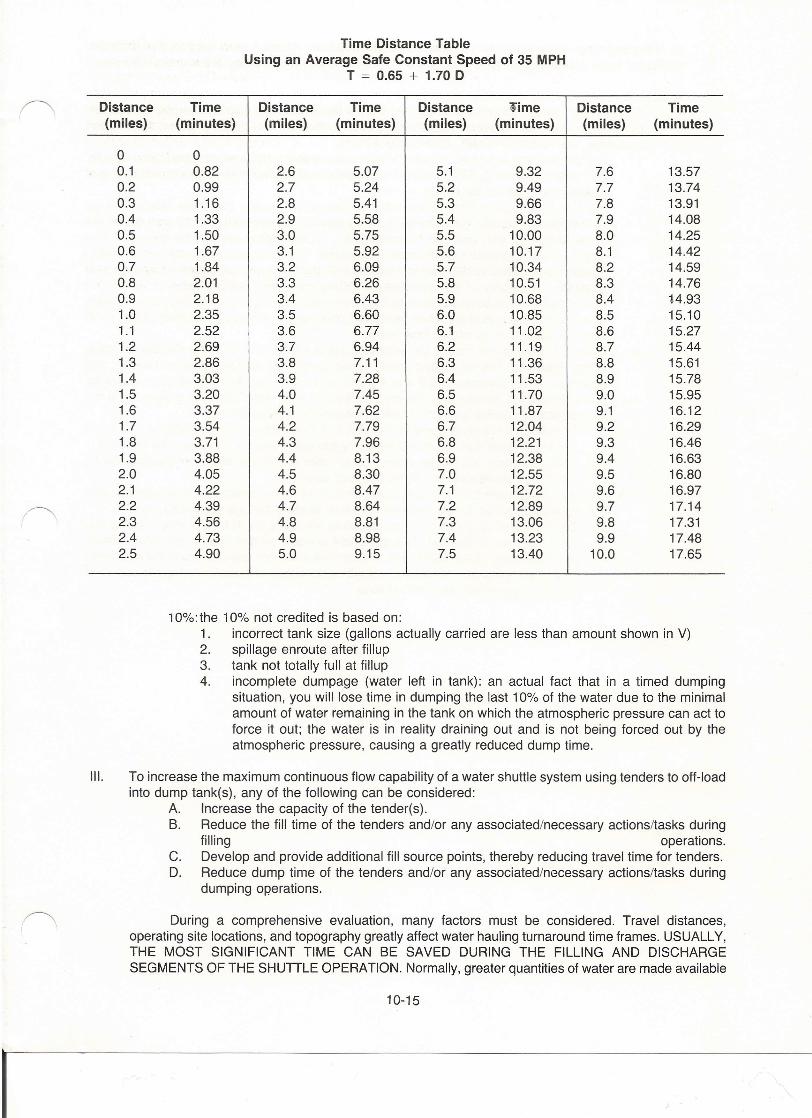
Time Distance TableUsing an Average Safe Constant Speed of 35 MPH
T = 0.65 + 1.70 D
Distance Time Distance Time Distance lime Distance Time(miles) (minutes) (miles) (minutes) (miles) (minutes) (miles) (minutes)
0 00.1 0.82 2.6 5.07 5.1 9.32 7.6 13.570.2 0.99 2.7 5.24 5.2 9.49 7.7 13.740.3 1.16 2.8 5.41 5.3 9.66 7.8 13.910.4 1.33 2.9 5.58 5.4 9.83 7.9 14.080.5 1.50 3.0 5.75 5.5 10.00 8.0 14.250.6 1.67 3.1 5.92 5.6 10.17 8.1 14.420.7 1.84 3.2 6.09 5.7 10.34 8.2 14.590.8 2.01 3.3 6.26 5.8 10.51 8.3 14.760.9 2.18 3.4 6.43 5.9 10.68 8.4 14.931.0 2.35 3.5 6.60 6.0 10.85 8.5 15.101.1 2.52 3.6 6.77 6.1 11.02 8.6 15.271.2 2.69 3.7 6.94 6.2 11.19 8.7 15.441.3 2.86 3.8 7.11 6.3 11.36 8.8 15.611.4 3.03 3.9 7.28 6.4 11.53 8.9 15.781.5 3.20 4.0 7.45 6.5 11.70 9.0 15.951.6 3.37 4.1 7.62 6.6 11.87 9.1 16.121.7 3.54 4.2 7.79 6.7 12.04 9.2 16.291.8 3.71 4.3 7.96 6.8 12.21 9.3 16.461.9 ..3.88 4.4 8.13 6.9 12.38 9.4 16.632.0 4.05 4.5 8.30 7.0 12.55 9.5 16.802.1 4.22 4.6 8.47 7.1 12.72 9.6 16.972.2 4.39 4.7 8.64 7.2 12.89 9.7 17.142.3 4.56 4.8 8.81 7.3 13.06 9.8 17.312.4 4.73 4.9 8.98 7.4 13.23 9.9 17.482.5 4.90 5.0 9.15 7.5 13.40 10.0 17.65
10%:the 10% not credited is based on:1. incorrect tank size (gallons actually carried are less than amount shown in V)2. spillage enroute after fillup3. tank not totally full at fillup4. incomplete dumpage (water left in tank): an actual fact that in a timed dumping
situation, you will lose time in dumping the last 10% of the water due to the minimalamount of water remaining in the tank on which the atmospheric pressure can act toforce it out; the water is in reality draining out and is not being forced out by theatmospheric pressure, causing a greatly reduced dump time.
III. To increase the maximum continuous flow capability of a water shuttle system using tenders to off-loadinto dump tank(s), any of the following can be considered:
A. Increase the capacity of the tender(s).B. Reduce the fill time of the tenders and/or any associated/necessary actions/tasks during
filling operations.C. Develop and provide additional fill source points, thereby reducing travel time for tenders.D. Reduce dump time of the tenders and/or any associated/necessary actions/tasks during
dumping operations.
During a comprehensive evaluation, many factors must be considered. Travel distances,operating site locations, and topography greatly affect water hauling turnaround time frames. USUALLY,THE MOST SIGNIFICANT TIME CAN BE SAVED DURING THE FILLING AND DISCHARGESEGMENTS OF THE SHUTILE OPERATION. Normally, greater quantities of water are made available
10-15
I

as filling/discharge rates increase. As rates increase, adequate logistics must support this increase.Additional water sources, tenders, and pumping units will ensure the adequacy of the overall increases.
IV. Additional calculations for automatic aid tenders:A. At this point, almost all water hauling tabulations have been calculated. However, if you are
planning to lower an insurance classification through the hauling/shuttle of water, there is stillone more, VERY IMPORTANT, CONSIDERATION.1. The formula that was used showed a 10% water amount that was not considered usable.
That 10% figure WILL APPLY ONLY to tenders housed/stationed in the district/zone thatis being surveyed for the rating.
2. The Fire Suppression Rating Schedule, Section 611 F, states that if the rate of flow byfire department supply (i.e., shuttle system) can be "increased within 15 minutes of thearrival at the fire site, and can be continued .... , this higher rate will be credited." Theincrease must be greater than the basic 250 gal/min. The automatic aid tenders will, in reality,provide the units that actually allow the initial 250 gal/min figure to be attained, and will alsocomprise the majority of the units used to initiate any higher delivery rates.
3. A map study should be undertaken to determine what area(s) of the fire district/zone beingsurveyed may have their quantities increased based on the amount of automatic aid supportavailable within the 15-minute time frame.
4. There is a definite point credit for automatic aid in section 512 D of the Fire SuppressionRating Schedule. The calculated credit, based on definite, stated activities, training, andequipment, is a maximum of 0.9 and a minimum of 0.3. The "score" that you receive forthe automatic aid section is extremely important in your water shuttling program and thecalculations toward the amount of water delivered to the fire scene.a. The decimal credit received for Section 512 D will be used by multiplying it to the Q
(gal/min) figure that you found for every run calculated for automatic aid tenders.b. Each automatic aid tender station could have a different credit for Section 512 D;
therefore calculations should be checked carefully.c. As can be seen from the above, the amount of water credited as being carried (and
delivered) will be further reduced for those tenders that are automatic aid.d. The delivered amounts that you calculate will apply for ALL runs made during any
particular fire/training/test. This statement is made so that there is no differentiationmade between initial responding run from the automatic aid stations to the supporteddistrict's fire and any/all shuttle runs within the supported district during the course ofthe fire suppression and related runs.
10-16
I/