
Users Manual...Users Manual 4 1. Screw the appropriate gauge adapter fully on to the instrument to...
20
PN 3952297 November 2010 © 2010 Fluke Corporation. All rights reserved. Printed in USA. Specifications are subject to change without notice. All product names are trademarks of their respective companies. P5510 Pneumatic Comparison Test Pump Users Manual 99 Washington Street Melrose, MA 02176 Phone 781-665-1400 Toll Free 1-800-517-8431 Visit us at www.TestEquipmentDepot.com
Transcript of Users Manual...Users Manual 4 1. Screw the appropriate gauge adapter fully on to the instrument to...
PN 3952297 November 2010 © 2010 Fluke Corporation. All rights reserved. Printed in USA. Specifications are subject to change without notice. All product names are trademarks of their respective companies.
P5510 Pneumatic Comparison Test Pump
Users Manual
99 Washington Street Melrose, MA 02176 Phone 781-665-1400Toll Free 1-800-517-8431
Visit us at www.TestEquipmentDepot.com
LIMITED WARRANTY AND LIMITATION OF LIABILITY
Each Fluke product is warranted to be free from defects in material and workmanship under normal use and service. The warranty period is one year and begins on the date of shipment. Parts, product repairs, and services are warranted for 90 days. This warranty extends only to the original buyer or end-user customer of a Fluke authorized reseller, and does not apply to fuses, disposable batteries, or to any product which, in Fluke's opinion, has been misused, altered, neglected, contaminated, or damaged by accident or abnormal conditions of operation or handling. Fluke warrants that software will operate substantially in accordance with its functional specifications for 90 days and that it has been properly recorded on non-defective media. Fluke does not warrant that software will be error free or operate without interruption.
Fluke authorized resellers shall extend this warranty on new and unused products to end-user customers only but have no authority to extend a greater or different warranty on behalf of Fluke. Warranty support is available only if product is purchased through a Fluke authorized sales outlet or Buyer has paid the applicable international price. Fluke reserves the right to invoice Buyer for importation costs of repair/replacement parts when product purchased in one country is submitted for repair in another country.
Fluke's warranty obligation is limited, at Fluke's option, to refund of the purchase price, free of charge repair, or replacement of a defective product which is returned to a Fluke authorized service center within the warranty period.
To obtain warranty service, contact your nearest Fluke authorized service center to obtain return authorization information, then send the product to that service center, with a description of the difficulty, postage and insurance prepaid (FOB Destination). Fluke assumes no risk for damage in transit. Following warranty repair, the product will be returned to Buyer, transportation prepaid (FOB Destination). If Fluke determines that failure was caused by neglect, misuse, contamination, alteration, accident, or abnormal condition of operation or handling, including overvoltage failures caused by use outside the product’s specified rating, or normal wear and tear of mechanical components, Fluke will provide an estimate of repair costs and obtain authorization before commencing the work. Following repair, the product will be returned to the Buyer transportation prepaid and the Buyer will be billed for the repair and return transportation charges (FOB Shipping Point).
THIS WARRANTY IS BUYER'S SOLE AND EXCLUSIVE REMEDY AND IS IN LIEU OF ALL OTHER WARRANTIES, EXPRESS OR IMPLIED, INCLUDING BUT NOT LIMITED TO ANY IMPLIED WARRANTY OF MERCHANTABILITY OR FITNESS FOR A PARTICULAR PURPOSE. FLUKE SHALL NOT BE LIABLE FOR ANY SPECIAL, INDIRECT, INCIDENTAL, OR CONSEQUENTIAL DAMAGES OR LOSSES, INCLUDING LOSS OF DATA, ARISING FROM ANY CAUSE OR THEORY.
Since some countries or states do not allow limitation of the term of an implied warranty, or exclusion or limitation of incidental or consequential damages, the limitations and exclusions of this warranty may not apply to every buyer. If any provision of this Warranty is held invalid or unenforceable by a court or other decision-maker of competent jurisdiction, such holding will not affect the validity or enforceability of any other provision.
i
Table of Contents
Title Page
Introduction........................................................................................................ 1 Operating Ranges............................................................................................... 1 How to Contact Fluke ........................................................................................ 2 Safety Information ............................................................................................. 2
Safety Summary ............................................................................................ 2 Compressed Gas ............................................................................................ 2 Personal Protective Equipment...................................................................... 2 Symbols Used in this Manual........................................................................ 2
Connections ....................................................................................................... 3 Test Port Insert................................................................................................... 6 Operation ........................................................................................................... 6
Vacuum ......................................................................................................... 6 Pressure ......................................................................................................... 7
Maintenance and Servicing................................................................................ 7 Contamination ............................................................................................... 7 Pump Removal .............................................................................................. 8 Pump Disassembly ........................................................................................ 8 Cleaning & Inspection................................................................................... 8 Pump Reassembly ......................................................................................... 8
Ancillary Equipment.......................................................................................... 10 Dirt/Moisture Trap, P5531 ............................................................................ 10 Angle Adapter, P5543 ................................................................................... 10 Pointer Remover/Punch, P5551..................................................................... 11

P5510 Users Manual
ii
iii
List of Tables
Table Title Page
1. Mode and Maximum Working Pressure ................................................................ 1 2. Symbols.................................................................................................................. 3 3. Test Port Insert - Parts List..................................................................................... 6 4. Handpump Assembly - Parts List........................................................................... 9
Test Equipment Depot - 800.517.8431 - 99 Washington Street Melrose, MA 02176TestEquipmentDepot.com

P5510 Users Manual
iv
v
List of Figures
Figure Title Page
1. Fitting Gauge Adapter............................................................................................ 4 2. Connect Assembly to Test Port .............................................................................. 4 3. Hand Tighten Only................................................................................................. 4 4. Adjust Gauge Position............................................................................................ 5 5. Tighten Gauge Adapter .......................................................................................... 5 6. Hand Tighten Only................................................................................................. 5 8. Handpump Assembly ............................................................................................. 9 9. Dirt/Moisture Trap ................................................................................................. 10 10. Angle Adapter ........................................................................................................ 10 11. Pointer Remover/Punch.......................................................................................... 11

P5510 Users Manual
vi
1
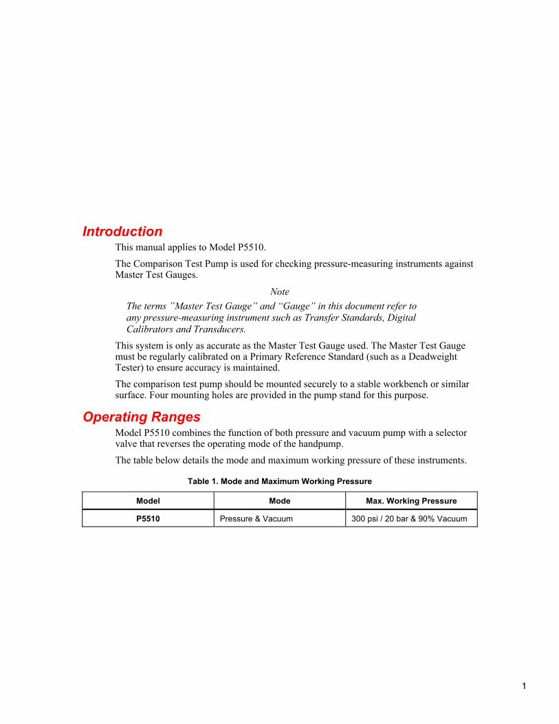
Introduction This manual applies to Model P5510. The Comparison Test Pump is used for checking pressure-measuring instruments against Master Test Gauges.
Note The terms ”Master Test Gauge” and “Gauge” in this document refer to any pressure-measuring instrument such as Transfer Standards, Digital Calibrators and Transducers.
This system is only as accurate as the Master Test Gauge used. The Master Test Gauge must be regularly calibrated on a Primary Reference Standard (such as a Deadweight Tester) to ensure accuracy is maintained. The comparison test pump should be mounted securely to a stable workbench or similar surface. Four mounting holes are provided in the pump stand for this purpose.
Operating Ranges Model P5510 combines the function of both pressure and vacuum pump with a selector valve that reverses the operating mode of the handpump. The table below details the mode and maximum working pressure of these instruments.
Table 1. Mode and Maximum Working Pressure
Model Mode Max. Working Pressure
P5510 Pressure & Vacuum 300 psi / 20 bar & 90% Vacuum

P5510 Users Manual
2
Safety Information W Warning
Read before Pneumatic Comparison Test Pump use. To prevent possible equipment damage or personal injury, follow these guidelines.
Safety Summary The following are general safety precautions that are not related to any specific procedures and do not appear elsewhere in this publication. These are recommended precautions that personnel must understand and apply during equipment operation and maintenance to ensure safety and health and protection of property.
Compressed Gas Use of compressed gasses can create an environment of propelled foreign matter. Pressure system safety precautions apply to all ranges of pressure. Care must be taken during testing to ensure that all pneumatic connections are properly and tightly made prior to applying pressure. Personnel must wear eye protection to prevent injury.
Personal Protective Equipment Wear eye protection approved for the materials and tools being used.
Symbols Used in this Manual In this manual, a Warning identifies conditions and actions that pose a hazard to the user. A Caution identifies conditions and actions that may damage the Pneumatic Comparison Test Pump.
Test Equipment Depot - 800.517.8431 - 99 Washington Street Melrose, MA 02176TestEquipmentDepot.com
Pneumatic Comparison Test Pump Connections
3
Symbols used on the Pneumatic Comparison Test Pump and in this manual are explained in Table 2.
Table 2. Symbols
Symbol Description
B AC (Alternating Current)
J Earth Ground
W Important Information: refer to manual
~ Do not dispose of this product as unsorted municipal waste. Go to Fluke’s website for recycling information.
Connections Fit the device under test (DUT) to the test port using the method described below:
W Caution Ensure that all devices are internally clean and free from contamination before connecting to the tester. Particle contamination can damage the sensitive piston assemblies, valve seats and screw pump. To avoid contamination from moisture, and protect the system from particulates, we recommend the use of a P5531 Dirt/Moisture Trap. (Refer section Ancillary Equipment).
W Warning DO NOT use Teflon/PTFE tape on these connections, as this will prevent correct sealing. The Gauge Adapter sealing system is designed for hand-tight sealing up to 20,000 psi / 1,400 bar-wrenches or similar tools are not required — over tightening can cause damage to threads or sealing faces. Before connection, ensure that there is an O-ring fitted to the test port.
Check that the sealing face of the device to be fitted is clean and undamaged, as scratches or dents can form leak-paths.
Note The thread on the test port, and the lower part of the gauge adapters is LEFT-HANDED. The following procedure details the correct method for mounting devices using these adapters:
P5510 Users Manual
4
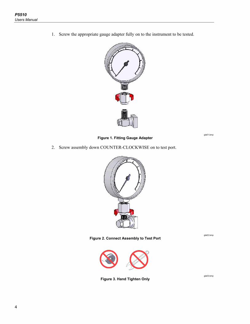
1. Screw the appropriate gauge adapter fully on to the instrument to be tested.
gla01.bmp
Figure 1. Fitting Gauge Adapter
2. Screw assembly down COUNTER-CLOCKWISE on to test port.
gla02.bmp
Figure 2. Connect Assembly to Test Port
gla03.bmp
Figure 3. Hand Tighten Only
Pneumatic Comparison Test Pump Connections
5
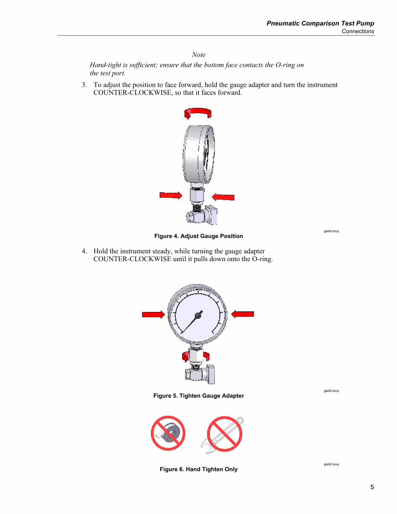
Note Hand-tight is sufficient; ensure that the bottom face contacts the O-ring on the test port.
3. To adjust the position to face forward, hold the gauge adapter and turn the instrument COUNTER-CLOCKWISE, so that it faces forward.
gla04.bmp
Figure 4. Adjust Gauge Position
4. Hold the instrument steady, while turning the gauge adapter COUNTER-CLOCKWISE until it pulls down onto the O-ring.
gla05.bmp
Figure 5. Tighten Gauge Adapter
gla06.bmp
Figure 6. Hand Tighten Only
P5510 Users Manual
6
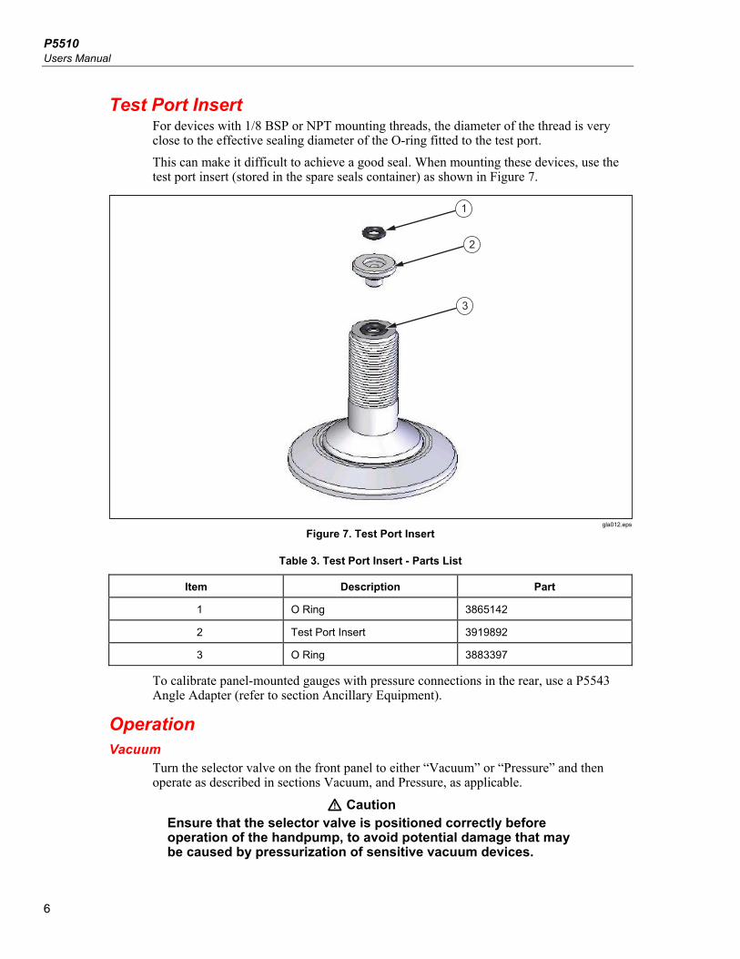
Test Port Insert For devices with 1/8 BSP or NPT mounting threads, the diameter of the thread is very close to the effective sealing diameter of the O-ring fitted to the test port. This can make it difficult to achieve a good seal. When mounting these devices, use the test port insert (stored in the spare seals container) as shown in Figure 7.
3
2
1
gla012.eps
Figure 7. Test Port Insert
Table 3. Test Port Insert - Parts List
Item Description Part
1 O Ring 3865142
2 Test Port Insert 3919892
3 O Ring 3883397
To calibrate panel-mounted gauges with pressure connections in the rear, use a P5543 Angle Adapter (refer to section Ancillary Equipment).
Operation Vacuum
Turn the selector valve on the front panel to either “Vacuum” or “Pressure” and then operate as described in sections Vacuum, and Pressure, as applicable.
W Caution Ensure that the selector valve is positioned correctly before operation of the handpump, to avoid potential damage that may be caused by pressurization of sensitive vacuum devices.
Pneumatic Comparison Test Pump Maintenance and Servicing
7
1. Ensure exhaust valve is closed — Do not over tighten, as damage to the valve seat can occur.
2. To generate a vacuum in the system, use the handpump until the desired reading is reached.
3. Allow a few moments for the system to stabilize before taking any readings, especially after large changes in system pressure.
Note Large, sudden changes in pressure will cause the system temperature to rise or fall, which can cause instrument readings to change as the gas in the system expands or contracts, thus increasing or decreasing the pressure.
4. For the next, higher vacuum point; repeat from 2 above. 5. For lower points, slowly open and close exhaust valve, allowing air into the system. 6. After calibration, always equalize the system pressure by slowly opening the exhaust
valve.
Pressure 1. Ensure exhaust valve is closed — Do not over tighten, as damage to the valve seat
can occur. 2. To increase the system pressure, use the handpump until the desired pressure is
reached. 3. Allow a few moments for the system to stabilize before taking any readings,
especially after large changes in system pressure.
Note Large, sudden changes in pressure will cause the system temperature to rise or fall, which can cause instrument readings to change as the gas in the system expands or contracts, thus increasing or decreasing the pressure.
4. For the next, higher pressure point, repeat from 2 above. 5. To reduce system pressure, slowly open and close exhaust valve until the desired
pressure is reached. 6. Before taking any readings, allow a few moments for the system to stabilize as before. 7. After calibration, always vent system pressure by slowly opening the exhaust valve. During operation, air is drawn into the pump assembly through the upper port in the pump cylinder (13) when the piston is lifted, and expelled through the lower port when the piston is pushed down.
Maintenance and Servicing The part number for the replacement seal kit is P5510SK.
Contamination W Caution
If the system becomes contaminated with dirt or moisture the instrument must be disassembled and cleaned, otherwise the pump may become damaged beyond repair.
Pump Removal 1. Remove unit from bench such that it can be turned over.
Test Equipment Depot - 800.517.8431 - 99 Washington Street Melrose, MA 02176TestEquipmentDepot.com
P5510 Users Manual
8
2. Remove 4 screws from sides of the housing (2 each side), and lift out cover plate from underside.
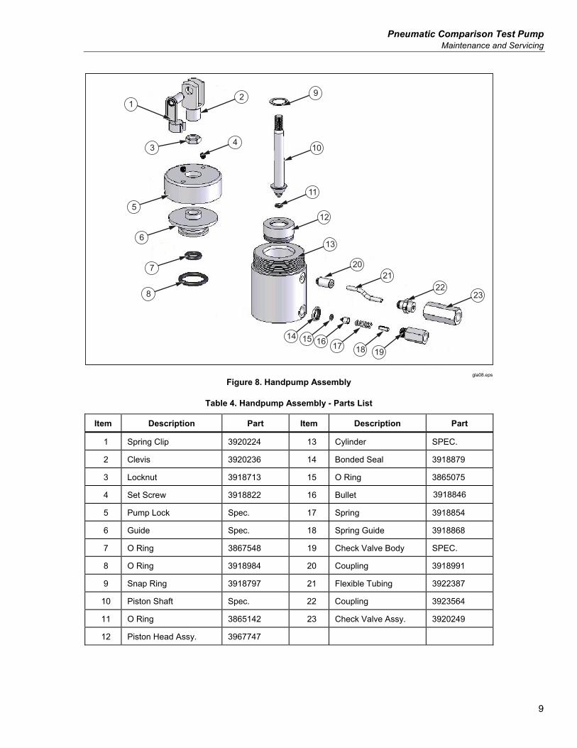
3. Disconnect nylon tubing from check valves (23) and (19). 4. Loosen locknut (3) approximately 1 turn. 5. Remove spring clip (1) from clevis (2), and swing the pump handle out of the way. 6. Unscrew clevis from piston shaft. 7. Loosen set screws (4) approximately 1 turn, and unscrew pump lock (5). 8. Pump assembly can be withdrawn from the instrument housing.
Pump Disassembly 1. Disassemble outlet check valve assembly, by unscrewing valve body (19). Take care
not to loose the small internal items that may spring out. 2. Disassemble inlet check valve assembly. If there is any doubt about the functionality
of the in-line check valve (23) it should be replaced, as it is difficult to clean effectively.
3. Remove guide (6) from cylinder (13) — take care not to damage this, as it is a tight fit within the cylinder.
4. Remove piston assembly from cylinder (13). 5. The piston head assembly (12) can be separated from the piston shaft (10) by
removing the snap ring (9).
Cleaning & Inspection Note
The piston head assembly cannot be further disassembled without damage to the components, so it must be wiped clean with a soft cloth to remove any contamination.
Check all seals for signs of wear and/or damage. Check the cylinder bore for signs of excessive wear, scratches/scoring, etc. Replacement seals are available; however, if there is significant damage to the internal components, the pump is available as a replacement assembly.
Pump Reassembly 1. Reassembly is the reverse of the above disassembly instructions. 2. Care should be taken whenever a seal comes in contact with metal components, to
avoid damage to the seal from sharp edges, etc. Examples:
• When introducing the piston head assembly (12) into the cylinder (13). • When introducing the piston shaft (10) through the central hole in the guide (6). • When introducing the guide (6) into the cylinder (13).
Pneumatic Comparison Test Pump Maintenance and Servicing
9
2
4
9
10
11
12
13
14 15 16 17 18 19
2021
2223
1
3
5
6
7
8
gla08.eps
Figure 8. Handpump Assembly
Table 4. Handpump Assembly - Parts List
Item Description Part Item Description Part
1 Spring Clip 3920224 13 Cylinder SPEC.
2 Clevis 3920236 14 Bonded Seal 3918879
3 Locknut 3918713 15 O Ring 3865075
4 Set Screw 3918822 16 Bullet 3918846
5 Pump Lock Spec. 17 Spring 3918854
6 Guide Spec. 18 Spring Guide 3918868
7 O Ring 3867548 19 Check Valve Body SPEC.
8 O Ring 3918984 20 Coupling 3918991
9 Snap Ring 3918797 21 Flexible Tubing 3922387
10 Piston Shaft Spec. 22 Coupling 3923564
11 O Ring 3865142 23 Check Valve Assy. 3920249
12 Piston Head Assy. 3967747
P5510 Users Manual
10
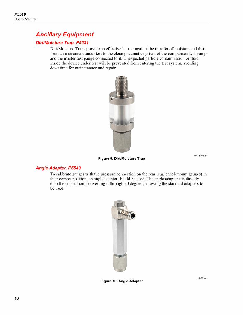
Ancillary Equipment Dirt/Moisture Trap, P5531
Dirt/Moisture Traps provide an effective barrier against the transfer of moisture and dirt from an instrument under test to the clean pneumatic system of the comparison test pump and the master test gauge connected to it. Unexpected particle contamination or fluid inside the device under test will be prevented from entering the test system, avoiding downtime for maintenance and repair.
5531 lp trap.jpg
Figure 9. Dirt/Moisture Trap
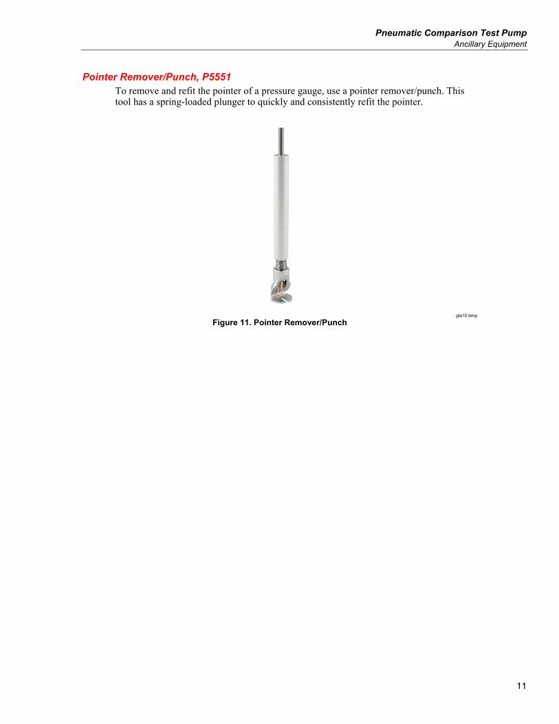
Angle Adapter, P5543 To calibrate gauges with the pressure connection on the rear (e.g. panel-mount gauges) in their correct position, an angle adapter should be used. The angle adapter fits directly onto the test station, converting it through 90 degrees, allowing the standard adapters to be used.
gla09.bmp
Figure 10. Angle Adapter
Pneumatic Comparison Test Pump Ancillary Equipment
11
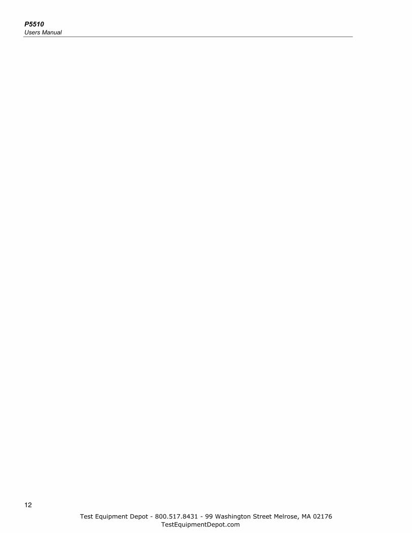
Pointer Remover/Punch, P5551 To remove and refit the pointer of a pressure gauge, use a pointer remover/punch. This tool has a spring-loaded plunger to quickly and consistently refit the pointer.
gla10.bmp
Figure 11. Pointer Remover/Punch
P5510 Users Manual
12
Test Equipment Depot - 800.517.8431 - 99 Washington Street Melrose, MA 02176TestEquipmentDepot.com


