USER’S MANUAL S MANUAL Serial Number Decal Model No. WLEL31216.0 Serial No. Write the serial...
24
USER’S MANUAL www.weslo.com Serial Number Decal Model No. WLEL31216.0 Serial No. Write the serial number in the space above for reference. CAUTION Read all precautions and instructions in this manual before using this equipment. Keep this manual for future reference. To register your product and activate your warranty today, go to www.wesloservice.com/ registration. For service at any time, go to www.wesloservice.com. Or call 1-866-699-3756 Mon.–Fri. 6 a.m.–6 p.m. MT Sat. 8 a.m.–12 p.m. MT Please do not contact the store. ACTIVATE YOUR WARRANTY CUSTOMER CARE
Transcript of USER’S MANUAL S MANUAL Serial Number Decal Model No. WLEL31216.0 Serial No. Write the serial...

USER’S MANUALwww.weslo.com
Serial Number Decal
Model No. WLEL31216.0Serial No.
Write the serial number in the space above for reference.
CAUTIONRead all precautions and instructions in this manual before using this equipment. Keep this manual for future reference.
To register your product and activate your warranty today, go to www.wesloservice.com/registration.
For service at any time, go to www.wesloservice.com.
Or call 1-866-699-3756Mon.–Fri. 6 a.m.–6 p.m. MTSat. 8 a.m.–12 p.m. MT
Please do not contact the store.
ACTIVATE YOUR WARRANTY
CUSTOMER CARE

2
WARNING DECAL PLACEMENT
This drawing shows the location(s) of the warning decal(s). If a decal is missing or illegible, see the front cover of this manual and request a free replace-ment decal. Apply the decal in the location shown. Note: The decal(s) may not be shown at actual size.
WESLO is a registered trademark of ICON Health & Fitness, Inc.
WARNING DECAL PLACEMENT . . . . . . . . . . . . . . . . . . . . . . . . . . . . . . . . . . . . . . . . . . . . . . . . . . . . . . . . . . . . . . .2IMPORTANT PRECAUTIONS . . . . . . . . . . . . . . . . . . . . . . . . . . . . . . . . . . . . . . . . . . . . . . . . . . . . . . . . . . . . . . . . . .3BEFORE YOU BEGIN. . . . . . . . . . . . . . . . . . . . . . . . . . . . . . . . . . . . . . . . . . . . . . . . . . . . . . . . . . . . . . . . . . . . . . . .5PART IDENTIFICATION CHART. . . . . . . . . . . . . . . . . . . . . . . . . . . . . . . . . . . . . . . . . . . . . . . . . . . . . . . . . . . . . . . .6ASSEMBLY . . . . . . . . . . . . . . . . . . . . . . . . . . . . . . . . . . . . . . . . . . . . . . . . . . . . . . . . . . . . . . . . . . . . . . . . . . . . . . . .7HOW TO USE THE STEPPER CLIMBER. . . . . . . . . . . . . . . . . . . . . . . . . . . . . . . . . . . . . . . . . . . . . . . . . . . . . . . .14FCC INFORMATION . . . . . . . . . . . . . . . . . . . . . . . . . . . . . . . . . . . . . . . . . . . . . . . . . . . . . . . . . . . . . . . . . . . . . . . .17MAINTENANCE AND TROUBLESHOOTING . . . . . . . . . . . . . . . . . . . . . . . . . . . . . . . . . . . . . . . . . . . . . . . . . . . . .18EXERCISE GUIDELINES . . . . . . . . . . . . . . . . . . . . . . . . . . . . . . . . . . . . . . . . . . . . . . . . . . . . . . . . . . . . . . . . . . . .19PART LIST. . . . . . . . . . . . . . . . . . . . . . . . . . . . . . . . . . . . . . . . . . . . . . . . . . . . . . . . . . . . . . . . . . . . . . . . . . . . . . . .21EXPLODED DRAWING. . . . . . . . . . . . . . . . . . . . . . . . . . . . . . . . . . . . . . . . . . . . . . . . . . . . . . . . . . . . . . . . . . . . . .22ORDERING REPLACEMENT PARTS . . . . . . . . . . . . . . . . . . . . . . . . . . . . . . . . . . . . . . . . . . . . . . . . . . Back CoverLIMITED WARRANTY. . . . . . . . . . . . . . . . . . . . . . . . . . . . . . . . . . . . . . . . . . . . . . . . . . . . . . . . . . . . . . . Back Cover
TABLE OF CONTENTS

3
IMPORTANT PRECAUTIONS
WARNING: To reduce the risk of serious injury, read all important precautions and instructions in this manual and all warnings on your stepper climber before using your stepper climber. ICON assumes no responsibility for personal injury or property damage sustained by or through the use of this product.
1. It is the responsibility of the owner to ensure that all users of the stepper climber are adequately informed of all precautions.
2. Before beginning any exercise program, consult your physician. This is especially important for persons over age 35 or per-sons with pre-existing health problems.
3. The stepper climber is not intended for use by persons with reduced physical, sensory, or mental capabilities or lack of experience and knowledge, unless they are given super-vision or instruction about use of the stepper climber by someone responsible for their safety.
4. Use the stepper climber only as described in this manual.
5. The stepper climber is intended for home use only. Do not use the stepper climber in a commercial, rental, or institutional setting.
6. Keep the stepper climber indoors, away from moisture and dust. Do not put the stepper climber in a garage or covered patio, or near water.
7. Place the stepper climber on a level surface, with a mat beneath it to protect the floor or carpet. Make sure that there is at least 2 ft. (0.6 m) of clearance around the stepper climber.
8. Inspect and properly tighten all parts each time the stepper climber is used. Replace any worn parts immediately.
9. Keep children under age 13 and pets away from the stepper climber at all times.
10. The resistance cylinders become hot during use. Allow the resistance cylinders to cool before touching them.
11. Wear appropriate clothes while exercising; do not wear loose clothes that could become caught on the stepper climber. Always wear athletic shoes for foot protection.
12. The stepper climber should not be used by persons weighing more than 250 lbs. (113 kg).
13. Be careful when mounting and dismounting the stepper climber.
14. Always keep your back straight while using the stepper climber; do not arch your back.
15. Over exercising may result in serious injury or death. If you feel faint, if you become short of breath, or if you experience pain while exercising, stop immediately and cool down.
4
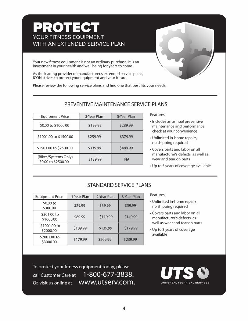
STANDARD SERVICE PLANS

5
BEFORE YOU BEGIN
Handlebar
Adjustment Pin
Resistance Knob
Resistance Cylinder
Adjustment Collar
Pedal
Leveling Foot
Console
Thank you for selecting the new WESLO® STEP FIT CLIMBER stepper climber. Stepping is one of the most effective exercises for increasing cardiovascular fitness, building endurance, and toning the entire body. The STEP FIT CLIMBER stepper climber provides a selection of features designed to make your workouts at home more effective and enjoyable.
For your benefit, read this manual carefully before you use the stepper climber. If you have questions
after reading this manual, please see the front cover of this manual. To help us assist you, note the product model number and serial number before contacting us. The model number and the location of the serial num-ber decal are shown on the front cover of this manual.
Before reading further, please review the drawing below and familiarize yourself with the labeled parts.
Height: 7 ft. 7 in. (231 cm)Length: 3 ft. 2 in. (97 cm)Width: 2 ft. 1 in. (64 cm)

6
M8 Locknut(69)–3
M10 Locknut (74)–1
M6 x 14mm Screw (81)–8
M8 x 16mm Screw (78)–2
M4 x 16mmScrew (82)–6
M10 x 20mm Screw (77)–4 M10 x 73mm Bolt (75)–1
M8 x 40mm Bolt (80)–2M8 x 35mm Bolt (68)–1 M8 x 68mm Screw (73)–4
PART IDENTIFICATION CHARTUse the drawings below to identify the small parts needed for assembly. The number in parentheses below each drawing is the key number of the part, from the PART LIST near the end of this manual. The number following the key number is the quantity needed for assembly. Note: If a part is not in the hardware kit, check to see if it has been preassembled. Extra parts may be included.

7
• To hire an authorized service technician to assemble this product, call 1-800-445-2480.
• Assembly requires two persons.
• Place all parts in a cleared area and remove the packing materials. Do not dispose of the packing materials until you complete all assembly steps.
• Left parts are marked “L” or “Left” and right parts are marked “R” or “Right.”
• To identify small parts, see page 6.
• In addition to the included tool(s), assembly requires the following tools:
one Phillips screwdriver
one adjustable wrench
Assembly may be easier if you have a set of wrenches. To avoid damaging parts, do not use power tools.
ASSEMBLY
1. Go to www.weslo.com/registration on your computer and register your product.
• activates your warranty
• saves you time if you ever need to contact Customer Care
• allows us to notify you of upgrades and offers
Note: If you do not have internet access, call Customer Care (see the front cover of this manual) and register your product.
1

8
2. Pull the Base Leg (10) assembly away from the Base (6) assembly and orient the parts as shown.
Attach the Base Leg (10) to the Base (6) with an M10 x 73mm Bolt (75) and an M10 Locknut (74); do not fully tighten the Locknut yet.
7475
6
6
10
11
10
69
2
3. Pull the Base Brace (11) away from the Base (6) and attach it to the Base Leg (10) with an M8 x 35mm Bolt (68) and an M8 Locknut (69).
Then, tighten the two indicated M10 Locknuts (74).
3
68
74

9
4. Orient the Front Stabilizer (13) so that the welded tubes (B) are in the locations shown.
Attach the Front Stabilizer (13) to the Base Leg (10) with two M8 x 68mm Screws (73).
4
10
B
C
73
73
13
12
55. Orient the Rear Stabilizer (12) so that the welded tubes (C) are in the locations shown.
Attach the Rear Stabilizer (12) to the Base (6) with two M8 x 68mm Screws (73).
6

10
6
7
6. Attach a Pedal (19) to the Left Pedal Leg (8) with four M6 x 14mm Screws (81); start all the Screws, and then tighten them.
Repeat this step on the other side of the stepper climber.
7. Attach the left Resistance Cylinder (9) to the Left Pedal Leg (8) with an M8 x 40mm Bolt (80) and an M8 Locknut (69).
Repeat this step on the other side of the stepper climber.
19
81
8
80
81
9
869

11
88. Tip: Avoid pinching the wires. With the help of a second person, attach the Frame (1) assembly to the Base (6) with four M10 x 20mm Screws (77); start all the Screws, and then tighten them.
Connect the Extension Wire (20) in the Frame (1) to the Reed Switch Wire (83) in the Base (6). Insert the excess wire into the Base or into the Frame.
9. Attach a Grip (14) to the left side of the Base (6) with an M8 x 16mm Screw (78).
Repeat this step on the other side of the stepper climber.
9
16
2083
77
78
146
Avoid pinching the wires

12
10. Orient a Handlebar (4) as shown.
Press and hold down the adjustment pin (D), insert the Handlebar into the Left Climbing Carriage (3), and then release the adjustment pin into one of the adjustment holes (E) in the Climbing Carriage.
Press the Handlebar Bracket (49) downward into the top of the Left Climbing Carriage (3).
Repeat this step on the other side of the stepper climber. Make sure to adjust the Handlebars (4) to the same height.
10
4D
49
3
E
11. Tip: Avoid pinching the wires. Attach the Front Frame Lower Cover (32) to the Rear Frame Cover (33) with two M4 x 16mm Screws (82).
11
32
82
33
Avoid pinching the wires
13
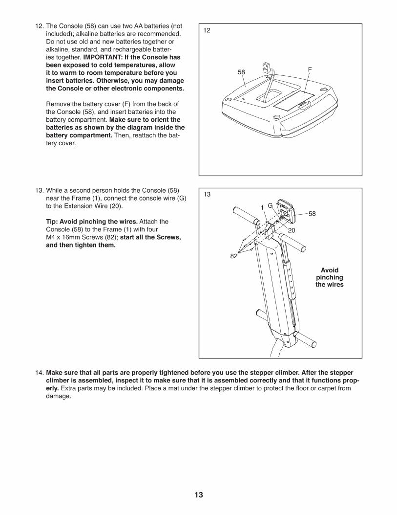
12. The Console (58) can use two AA batteries (not included); alkaline batteries are recommended. Do not use old and new batteries together or alkaline, standard, and rechargeable batter-ies together. IMPORTANT: If the Console has been exposed to cold temperatures, allow it to warm to room temperature before you insert batteries. Otherwise, you may damage the Console or other electronic components.
Remove the battery cover (F) from the back of the Console (58), and insert batteries into the battery compartment. Make sure to orient the batteries as shown by the diagram inside the battery compartment. Then, reattach the bat-tery cover.
12
58 F
14. Make sure that all parts are properly tightened before you use the stepper climber. After the stepper climber is assembled, inspect it to make sure that it is assembled correctly and that it functions prop-erly. Extra parts may be included. Place a mat under the stepper climber to protect the floor or carpet from damage.
13. While a second person holds the Console (58) near the Frame (1), connect the console wire (G) to the Extension Wire (20).
Tip: Avoid pinching the wires. Attach the Console (58) to the Frame (1) with four M4 x 16mm Screws (82); start all the Screws, and then tighten them.
13
Avoid pinching the wires
58G
20
82
1
14
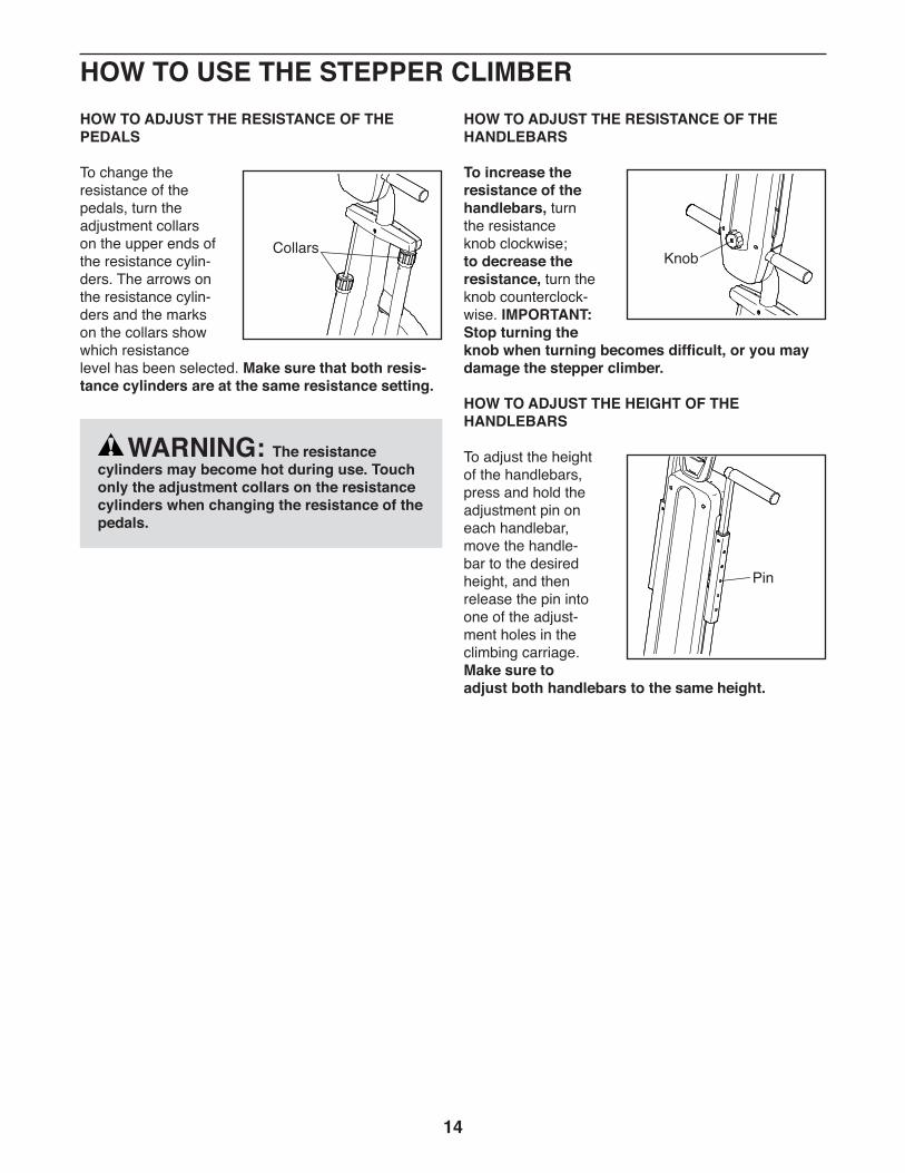
HOW TO ADJUST THE RESISTANCE OF THE PEDALS
To change the resistance of the pedals, turn the adjustment collars on the upper ends of the resistance cylin-ders. The arrows on the resistance cylin-ders and the marks on the collars show which resistance level has been selected. Make sure that both resis-tance cylinders are at the same resistance setting.
HOW TO ADJUST THE RESISTANCE OF THE HANDLEBARS
To increase the resistance of the handlebars, turn the resistance knob clockwise; to decrease the resistance, turn the knob counterclock-wise. IMPORTANT: Stop turning the knob when turning becomes difficult, or you may damage the stepper climber.
HOW TO ADJUST THE HEIGHT OF THE HANDLEBARS
To adjust the height of the handlebars, press and hold the adjustment pin on each handlebar, move the handle-bar to the desired height, and then release the pin into one of the adjust-ment holes in the climbing carriage. Make sure to adjust both handlebars to the same height.
Collars
WARNING: The resistance cylinders may become hot during use. Touch only the adjustment collars on the resistance cylinders when changing the resistance of the pedals.
Knob
Pin
HOW TO USE THE STEPPER CLIMBER
15
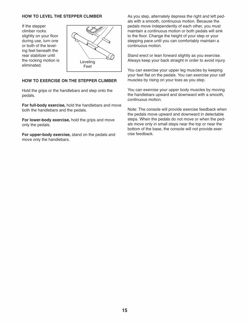
HOW TO LEVEL THE STEPPER CLIMBER
If the stepper climber rocks slightly on your floor during use, turn one or both of the level-ing feet beneath the rear stabilizer until the rocking motion is eliminated.
HOW TO EXERCISE ON THE STEPPER CLIMBER
Hold the grips or the handlebars and step onto the pedals.
For full-body exercise, hold the handlebars and move both the handlebars and the pedals.
For lower-body exercise, hold the grips and move only the pedals.
For upper-body exercise, stand on the pedals and move only the handlebars.
As you step, alternately depress the right and left ped-als with a smooth, continuous motion. Because the pedals move independently of each other, you must maintain a continuous motion or both pedals will sink to the floor. Change the height of your step or your stepping pace until you can comfortably maintain a continuous motion.
Stand erect or lean forward slightly as you exercise. Always keep your back straight in order to avoid injury.
You can exercise your upper leg muscles by keeping your feet flat on the pedals. You can exercise your calf muscles by rising on your toes as you step.
You can exercise your upper body muscles by moving the handlebars upward and downward with a smooth, continuous motion.
Note: The console will provide exercise feedback when the pedals move upward and downward in detectable steps. When the pedals do not move or when the ped-als move only in small steps near the top or near the bottom of the base, the console will not provide exer-cise feedback.
Leveling Feet

16
FEATURES OF THE CONSOLE
The easy-to-use console features five modes that pro-vide instant exercise feedback during your workouts.
Scan (SCAN)—This mode displays the time, calories, steps, and steps per minute modes, for a few seconds each, in a repeating cycle.
Time (TMR)—This mode displays the elapsed time. Note: If you set a time goal (see step 2), this display will show the time remaining in your workout.
Calories (CAL)—This mode displays the approximate number of calories you have burned during your work-out. Note: If you set a calorie-burning goal (see step 2), this mode will show the number of calories still to be burned in your workout.
Steps (ODO)—This mode displays the number of steps you have taken. Note: If you set a steps goal (see step 2), this mode will show the number of steps still to be completed in your workout.
Steps Per Minute (RPM)—This mode displays your stepping rate in steps per minute.
HOW TO USE THE CONSOLE
Make sure that batteries (not included) are installed in the console (see assembly step 12 on page 13). If there is a sheet of plastic on the console, remove the plastic.
IMPORTANT: The console will provide exercise feedback when the pedals move upward and down-ward in detectable steps. When the pedals do not move or when the pedals move only in small steps near the top or near the bottom of the base, the console will not provide exercise feedback.
1. Turn on the console.
To turn on the console, press any button on the console or simply begin stepping.
2. Set a workout goal if desired.
To set a time, calorie-burning, or steps goal for your workout, press the MODE button repeatedly until the letters TMR, CAL, or ODO appear in the display. Make sure that the word SCAN does not appear in the display.
Next, press the SET button repeatedly to set a goal. To set a goal quickly, hold down the SET but-ton. To reset the goal, press the RESET button.
3. Begin stepping and follow your progress with the display.
Scan mode—To select the scan mode, press the MODE button repeatedly until the word SCAN appears in the display.
Time, calories, steps, and steps per minute mode—To select one of these modes for continu-ous display, press the MODE button repeatedly until the name of the desired mode appears in the display. Make sure that the word SCAN does not appear in the display.
WichitaELWL31216
WLEL31216

17
As you exercise, the console will provide instant feedback. If you have set a workout goal, the display will show zeros and the console will beep when you reach your goal; if you continue to exer-cise, the display will begin to count upward.
To pause the console, stop stepping. The word STOP will appear in the display. To continue your workout, simply resume stepping.
To reset the display and all the modes to zero, press and hold the Reset button for several seconds.
4. When you are finished exercising, the console will turn off automatically.
If the pedals do not move for a few seconds, the console will pause.
The console has an auto-off feature. If the pedals do not move and the console buttons are not pressed for a few minutes, the power will turn off automatically to save the batteries.
FCC INFORMATIONThis equipment has been tested and found to comply with the limits for a Class B digital device, pursuant to Part 15 of the FCC Rules. These limits are designed to provide reasonable protection against harmful interference in a residential installation. This equipment generates, uses, and can radiate radio frequency energy and, if not installed and used in accordance with the instructions, may cause harmful interference to radio communications. However, there is no guarantee that interference will not occur in a particular installation. If this equipment does cause harmful interference to radio or television reception, which can be determined by turning the equipment off and on, try to correct the interference by one or more of the following measures:
• Reorient or relocate the receiving antenna.• Increase the separation between the equipment and the receiver.• Connect the equipment into an outlet on a circuit different from that to which the receiver is connected. • Consult the dealer or an experienced radio/TV technician for help.
FCC CAUTION: To assure continued compliance, use only shielded interface cables when connecting to computer or peripheral devices. Changes or modifications not expressly approved by the party respon-sible for compliance could void the user’s authority to operate this equipment.
18
MAINTENANCE
Regular maintenance is important for optimal performance and to reduce wear. Inspect and properly tighten all parts each time the stepper climber is used. Replace any worn parts immediately.
To clean the stepper climber, use a damp cloth and a small amount of mild soap. IMPORTANT: To avoid damage to the console, keep liquids away from the console and keep the console out of direct sunlight.
CONSOLE TROUBLESHOOTING
Most console problems are the result of low batteries; for replacement instructions, see assembly step 12 on page 13.
HOW TO ADJUST THE REED SWITCH
If the console does not display correct feedback when the pedals move in detectable steps, the reed switch should be adjusted.
Note: The console will provide exercise feedback when the pedals move upward and downward in detectable steps. When the pedals do not move or when the ped-als move only in small steps near the top or near the bottom of the base, the console will not provide exer-cise feedback.
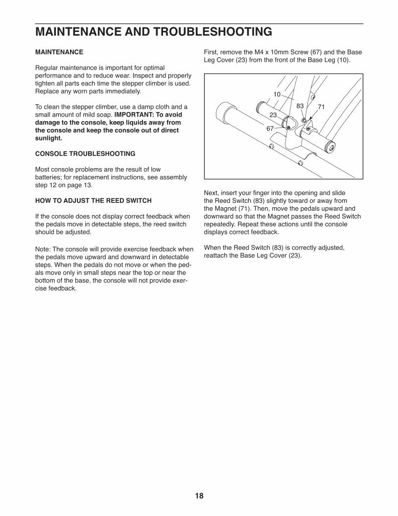
First, remove the M4 x 10mm Screw (67) and the Base Leg Cover (23) from the front of the Base Leg (10).
Next, insert your finger into the opening and slide the Reed Switch (83) slightly toward or away from the Magnet (71). Then, move the pedals upward and downward so that the Magnet passes the Reed Switch repeatedly. Repeat these actions until the console displays correct feedback.
When the Reed Switch (83) is correctly adjusted, reattach the Base Leg Cover (23).
MAINTENANCE AND TROUBLESHOOTING
8323
71
67
10

19
These guidelines will help you to plan your exercise program. For detailed exercise information, obtain a reputable book or consult your physician. Remember, proper nutrition and adequate rest are essential for successful results.
EXERCISE INTENSITY
Whether your goal is to burn fat or to strengthen your cardiovascular system, exercising at the proper inten-sity is the key to achieving results. You can use your heart rate as a guide to find the proper intensity level. The chart below shows recommended heart rates for fat burning and aerobic exercise.
To find the proper intensity level, find your age at the bottom of the chart (ages are rounded off to the near-est ten years). The three numbers listed above your age define your “training zone.” The lowest number is the heart rate for fat burning, the middle number is the heart rate for maximum fat burning, and the highest number is the heart rate for aerobic exercise.
Burning Fat—To burn fat effectively, you must exer-cise at a low intensity level for a sustained period of time. During the first few minutes of exercise, your body uses carbohydrate calories for energy. Only after the first few minutes of exercise does your body begin to use stored fat calories for energy. If your goal is to burn fat, adjust the intensity of your exercise until your heart rate is near the lowest number in your training zone. For maximum fat burning, exercise with your heart rate near the middle number in your training zone.
Aerobic Exercise—If your goal is to strengthen your cardiovascular system, you must perform aerobic exercise, which is activity that requires large amounts of oxygen for prolonged periods of time. For aerobic exercise, adjust the intensity of your exercise until your heart rate is near the highest number in your training zone.
HOW TO MEASURE YOUR HEART RATE
To measure your heart rate, exercise for at least four minutes. Then, stop exercising and place two fingers on your wrist as shown. Take a six-second heartbeat count, and multiply the result by 10 to find your heart rate. For example, if your six-second heartbeat count is 14, your heart rate is 140 beats per minute.
WORKOUT GUIDELINES
Warming Up—Start with 5 to 10 minutes of stretch-ing and light exercise. A warm-up increases your body temperature, heart rate, and circulation in preparation for exercise.
Training Zone Exercise—Exercise for 20 to 30 min-utes with your heart rate in your training zone. (During the first few weeks of your exercise program, do not keep your heart rate in your training zone for longer than 20 minutes.) Breathe regularly and deeply as you exercise; never hold your breath.
Cooling Down—Finish with 5 to 10 minutes of stretch-ing. Stretching increases the flexibility of your muscles and helps to prevent post-exercise problems.
EXERCISE FREQUENCY
To maintain or improve your condition, complete three workouts each week, with at least one day of rest between workouts. After a few months of regular exer-cise, you may complete up to five workouts each week, if desired. Remember, the key to success is to make exercise a regular and enjoyable part of your everyday life.
WARNING: Before beginning this or any exercise program, consult your physi-cian. This is especially important for persons over age 35 or persons with pre-existing health problems.
EXERCISE GUIDELINES
20
SUGGESTED STRETCHES
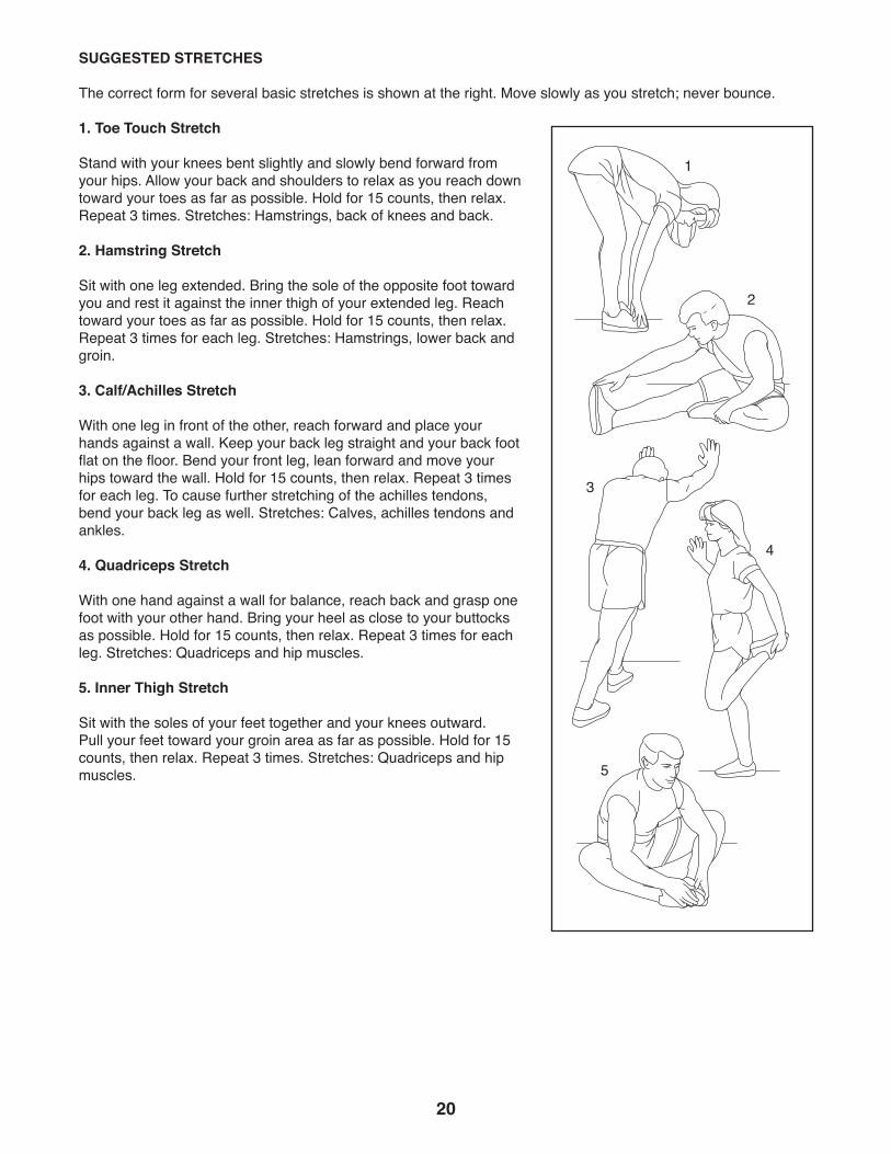
The correct form for several basic stretches is shown at the right. Move slowly as you stretch; never bounce.
1. Toe Touch Stretch
Stand with your knees bent slightly and slowly bend forward from your hips. Allow your back and shoulders to relax as you reach down toward your toes as far as possible. Hold for 15 counts, then relax. Repeat 3 times. Stretches: Hamstrings, back of knees and back.
2. Hamstring Stretch
Sit with one leg extended. Bring the sole of the opposite foot toward you and rest it against the inner thigh of your extended leg. Reach toward your toes as far as possible. Hold for 15 counts, then relax. Repeat 3 times for each leg. Stretches: Hamstrings, lower back and groin.
3. Calf/Achilles Stretch
With one leg in front of the other, reach forward and place your hands against a wall. Keep your back leg straight and your back foot flat on the floor. Bend your front leg, lean forward and move your hips toward the wall. Hold for 15 counts, then relax. Repeat 3 times for each leg. To cause further stretching of the achilles tendons, bend your back leg as well. Stretches: Calves, achilles tendons and ankles.
4. Quadriceps Stretch
With one hand against a wall for balance, reach back and grasp one foot with your other hand. Bring your heel as close to your buttocks as possible. Hold for 15 counts, then relax. Repeat 3 times for each leg. Stretches: Quadriceps and hip muscles.
5. Inner Thigh Stretch
Sit with the soles of your feet together and your knees outward. Pull your feet toward your groin area as far as possible. Hold for 15 counts, then relax. Repeat 3 times. Stretches: Quadriceps and hip muscles.
1
2
3
4
5

21
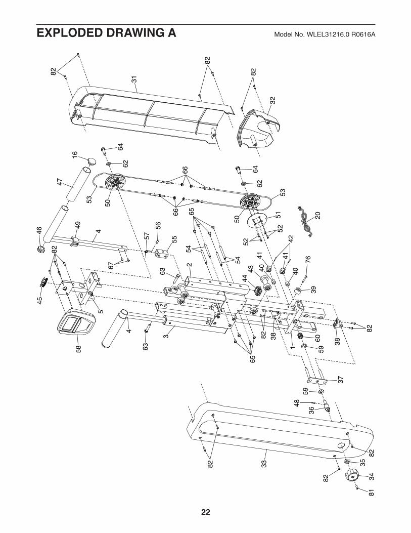
Note: Specifications are subject to change without notice. For information about ordering replacement parts, see the back cover of this manual. *These parts are not illustrated.
1 1 Frame 2 1 Right Climbing Carriage 3 1 Left Climbing Carriage 4 2 Handlebar 5 1 Console Bracket 6 1 Base 7 1 Right Pedal Leg 8 1 Left Pedal Leg 9 2 Resistance Cylinder 10 1 Base Leg 11 1 Base Brace 12 1 Rear Stabilizer 13 1 Front Stabilizer 14 2 Grip 15 2 Grip Foam 16 4 Grip Cap 17 4 Stabilizer Cap 18 2 Leveling Foot 19 2 Pedal/Strap 20 1 Extension Wire 21 1 Rear Base Cover 22 1 Front Base Cover 23 1 Base Leg Cover 24 2 Base Post Cover 25 2 Thrust Washer 26 4 Pedal Leg Bushing 27 4 M8 Washer 28 2 Pedal Leg Cover 29 2 M8 x 14mm Shoulder Screw 30 1 Magnet Bracket 31 1 Front Frame Upper Cover 32 1 Front Frame Lower Cover 33 1 Rear Frame Cover 34 1 Knob 35 1 Knob Bracket 36 1 Resistance Axle 37 1 Fork Bracket 38 2 Resistance Bracket 39 4 Carriage Bumper 40 2 Resistance Spacer 41 2 Brake 42 2 Brake Pin 43 8 Roller
44 2 Carriage Cap 45 1 Console Bracket Cap 46 2 Handlebar Cap 47 2 Handlebar Foam 48 1 Resistance Pin 49 2 Handlebar Bracket 50 2 Pulley 51 1 Brake Disc 52 4 Brake Screw 53 2 Cable 54 8 Axle 55 2 Handlebar Bushing 56 2 Snap Button 57 2 Snap Spring 58 1 Console 59 2 Resistance Washer 60 1 Resistance Spring 61 2 Pedal Leg Cap 62 2 M10 Washer 63 2 M8 x 38mm Screw 64 2 M10 x 30mm Screw 65 16 M5 x 10mm Flange Screw 66 8 M6 Nut 67 7 M4 x 10mm Screw 68 2 M8 x 35mm Bolt 69 4 M8 Locknut 70 1 Grommet 71 1 Magnet 72 2 Pad 73 4 M8 x 68mm Screw 74 2 M10 Locknut 75 2 M10 x 73mm Bolt 76 4 M6 x 30mm Screw 77 4 M10 x 20mm Screw 78 2 M8 x 16mm Screw 79 2 M8 x 18mm Screw 80 2 M8 x 40mm Bolt 81 9 M6 x 14mm Screw 82 24 M4 x 16mm Screw 83 1 Reed Switch/Wire * – User’sManual * – Assembly Tool
Key No. Qty. Description Key No. Qty. Description
PART LIST Model No. WLEL31216.0 R0616A
22
1
45
3
2
4
32
31
34
36
38
38
39
33 35
37
40 404141
43
46
16
50
50
52
52
45
4248
44
47
49
51
54
54
56
58
53
53
5557
60
63
81
63
6666 65
65
59
62
62
59
64
6467
20
82
82
82
82
82
82
76
88
82
82
82
8789
90
EXPLODED DRAWING A Model No. WLEL31216.0 R0616A

23
6
8
10
127
9
9
11
14
14
16
16
19
18
18
19
13
15
15
17
17
17
17
22
21
23
26
2628
30
25
61
24
27
27
27
29
68
6869
69
6970
72
71
7467
67
78
78
79
79
73
73
75
77 77
80
81
81
82
82
82
83
EXPLODED DRAWING B Model No. WLEL31216.0 R0616A

Part No. 381795 R0616A Printed in China © 2016 ICON Health & Fitness, Inc.
To order replacement parts, please see the front cover of this manual. To help us assist you, be prepared to provide the following information when contacting us:
• the model number and serial number of the product (see the front cover of this manual)
• the name of the product (see the front cover of this manual)
• the key number and description of the replacement part(s) (see the PART LIST and the EXPLODED DRAWING near the end of this manual)
ORDERING REPLACEMENT PARTS
ICON Health & Fitness, Inc. (ICON) warrants this product to be free from defects in workmanship and material, under normal use and service conditions. Parts and labor are warranted for ninety (90) days from the date of purchase.
Thiswarrantyextendsonlytotheoriginalpurchaser(customer).ICON’sobligationunderthiswarrantyislimitedtorepairingorreplacing,atICON’soption,theproductthroughoneofitsauthorizedservicecenters.All repairs for which warranty claims are made must be preauthorized by ICON. If the product is shipped toaservicecenter,freightchargestoandfromtheservicecenterwillbethecustomer’sresponsibility.Ifreplacement parts are shipped while the product is under warranty, the customer will be responsible for a minimal handling charge. For in-home service, the customer will be responsible for a minimal trip charge. This warranty does not extend to freight damage to the product. This warranty will automatically be voided if the product is used as a store display model, if the product is purchased or transported outside the USA, if all instructions in this manual are not followed, if the product is abused or improperly or abnormally used, oriftheproductisusedforcommercialorrentalpurposes.Nootherwarrantybeyondthatspecificallysetforth above is authorized by ICON.
ICON is not responsible or liable for indirect, special, or consequential damages arising out of or in con-nection with the use or performance of the product; damages with respect to any economic loss, loss of property,lossofrevenuesorprofits,lossofenjoymentoruse,orcostsofremovalorinstallation;orotherconsequential damages of any kind. Some states do not allow the exclusion or limitation of incidental or consequential damages. Accordingly, the above limitation may not apply to the customer.
The warranty extended hereunder is in lieu of any and all other warranties, and any implied warranties of merchantabilityorfitnessforaparticularpurposearelimitedintheirscopeanddurationtothetermssetforth herein. Some states do not allow limitations on how long an implied warranty lasts. Accordingly, the above limitation may not apply to the customer.
Thiswarrantyprovidesspecificlegalrights;thecustomermayhaveotherrightsthatvaryfromstatetostate.
ICON Health & Fitness, Inc., 1500 S. 1000 W., Logan, UT 84321-9813
LIMITED WARRANTYIMPORTANT: To protect your fitness equipment with an extended service plan, see page 4.