User’s Manual PROFIBUS-DP Adapter Module RPBA … · Introduction 9 Introduction Intended...
70
ABB Drives User’s Manual PROFIBUS-DP Adapter Module RPBA-01
Transcript of User’s Manual PROFIBUS-DP Adapter Module RPBA … · Introduction 9 Introduction Intended...
ABB Drives
User’s ManualPROFIBUS-DP Adapter Module RPBA-01


PROFIBUS-DP Adapter ModuleRPBA-01
User’s Manual
3AFE 64504215 REV E EN
EFFECTIVE: 13.10.2003
2003 ABB Oy. All Rights Reserved.


5
Safety instructions
OverviewThis chapter states the general safety instructions that must be followed when installing and operating the RPBA-01 PROFIBUS-DP Adapter module.
The material in this chapter must be studied before attempting any work on, or with, the unit.
In addition to the safety instructions given below, read the complete safety instructions of the specific drive you are working on.
General safety instructionsWARNING! All electrical installation and maintenance work on the drive should be carried out by qualified electricians.
The drive and adjoining equipment must be properly earthed.
Do not attempt any work on a powered drive. After switching off the mains, always allow the intermediate circuit capacitors 5 minutes to discharge before working on the frequency converter, the motor or the motor cable. It is good practice to check (with a voltage indicating instrument) that the drive is in fact discharged before beginning work.
The motor cable terminals of the drive are at a dangerously high voltage when mains power is applied, regardless of motor operation.
There can be dangerous voltages inside the drive from external control circuits even when the drive mains power is shut off. Exercise appropriate care when working on the unit. Neglecting these instructions can cause physical injury or death.
Safety instructions

6
Safety instructions
7
Table of contents
Safety instructions . . . . . . . . . . . . . . . . . . . . . . . . . . . . . . . . . . . . . . . . . . . . 5
Overview . . . . . . . . . . . . . . . . . . . . . . . . . . . . . . . . . . . . . . . . . . . . . . . . . . . . 5General safety instructions . . . . . . . . . . . . . . . . . . . . . . . . . . . . . . . . . . . . . . . 5
Table of contents . . . . . . . . . . . . . . . . . . . . . . . . . . . . . . . . . . . . . . . . . . . . . 7
Introduction . . . . . . . . . . . . . . . . . . . . . . . . . . . . . . . . . . . . . . . . . . . . . . . . . 9
Intended audience . . . . . . . . . . . . . . . . . . . . . . . . . . . . . . . . . . . . . . . . . . . . . 9Before you start . . . . . . . . . . . . . . . . . . . . . . . . . . . . . . . . . . . . . . . . . . . . . . . 9What this manual contains . . . . . . . . . . . . . . . . . . . . . . . . . . . . . . . . . . . . . . . 9Terms used in this manual . . . . . . . . . . . . . . . . . . . . . . . . . . . . . . . . . . . . . . 11Further information . . . . . . . . . . . . . . . . . . . . . . . . . . . . . . . . . . . . . . . . . . . . 11
Overview . . . . . . . . . . . . . . . . . . . . . . . . . . . . . . . . . . . . . . . . . . . . . . . . . . . 13
Overview . . . . . . . . . . . . . . . . . . . . . . . . . . . . . . . . . . . . . . . . . . . . . . . . . . . 13PROFIBUS standard . . . . . . . . . . . . . . . . . . . . . . . . . . . . . . . . . . . . . . . . . . 13The RPBA-01 PROFIBUS-DP Adapter module . . . . . . . . . . . . . . . . . . . . . . 14
Compatibility . . . . . . . . . . . . . . . . . . . . . . . . . . . . . . . . . . . . . . . . . . . . . . . 15Delivery check . . . . . . . . . . . . . . . . . . . . . . . . . . . . . . . . . . . . . . . . . . . . . 15Warranty and liability information . . . . . . . . . . . . . . . . . . . . . . . . . . . . . . . 16
Mechanical installation . . . . . . . . . . . . . . . . . . . . . . . . . . . . . . . . . . . . . . . 17
Mounting . . . . . . . . . . . . . . . . . . . . . . . . . . . . . . . . . . . . . . . . . . . . . . . . . . . 17
Electrical installation . . . . . . . . . . . . . . . . . . . . . . . . . . . . . . . . . . . . . . . . . 19
Overview . . . . . . . . . . . . . . . . . . . . . . . . . . . . . . . . . . . . . . . . . . . . . . . . . . . 19General cabling instructions . . . . . . . . . . . . . . . . . . . . . . . . . . . . . . . . . . . . . 19Bus termination . . . . . . . . . . . . . . . . . . . . . . . . . . . . . . . . . . . . . . . . . . . . . . 19
Table of contents

8
Node selection . . . . . . . . . . . . . . . . . . . . . . . . . . . . . . . . . . . . . . . . . . . . . . . 20PROFIBUS connection . . . . . . . . . . . . . . . . . . . . . . . . . . . . . . . . . . . . . . . . . 21
Programming . . . . . . . . . . . . . . . . . . . . . . . . . . . . . . . . . . . . . . . . . . . . . . . . 23
Overview . . . . . . . . . . . . . . . . . . . . . . . . . . . . . . . . . . . . . . . . . . . . . . . . . . . . 23Configuring the system . . . . . . . . . . . . . . . . . . . . . . . . . . . . . . . . . . . . . . . . . 23
PROFIBUS connection configuration . . . . . . . . . . . . . . . . . . . . . . . . . . . . 23Control locations . . . . . . . . . . . . . . . . . . . . . . . . . . . . . . . . . . . . . . . . . . . . . . 27
Communication . . . . . . . . . . . . . . . . . . . . . . . . . . . . . . . . . . . . . . . . . . . . . . 29
Overview . . . . . . . . . . . . . . . . . . . . . . . . . . . . . . . . . . . . . . . . . . . . . . . . . . . . 29PROFIBUS-DP . . . . . . . . . . . . . . . . . . . . . . . . . . . . . . . . . . . . . . . . . . . . . . . 29
Service Access Points . . . . . . . . . . . . . . . . . . . . . . . . . . . . . . . . . . . . . . . . 29Communication start-up . . . . . . . . . . . . . . . . . . . . . . . . . . . . . . . . . . . . . . 30
PPO message types . . . . . . . . . . . . . . . . . . . . . . . . . . . . . . . . . . . . . . . . . . . 35The Control Word and the Status Word . . . . . . . . . . . . . . . . . . . . . . . . . . 36References . . . . . . . . . . . . . . . . . . . . . . . . . . . . . . . . . . . . . . . . . . . . . . . . 36Actual Values . . . . . . . . . . . . . . . . . . . . . . . . . . . . . . . . . . . . . . . . . . . . . . 36
Parameter handling in cyclic communication (DP) . . . . . . . . . . . . . . . . . . . . 41
Fault tracing . . . . . . . . . . . . . . . . . . . . . . . . . . . . . . . . . . . . . . . . . . . . . . . . 53
LED indications . . . . . . . . . . . . . . . . . . . . . . . . . . . . . . . . . . . . . . . . . . . . . . . 53
PROFIdrive parameters . . . . . . . . . . . . . . . . . . . . . . . . . . . . . . . . . . . . . . . 55
Definitions and abbreviations . . . . . . . . . . . . . . . . . . . . . . . . . . . . . . . . . . 61
PROFIBUS definitions . . . . . . . . . . . . . . . . . . . . . . . . . . . . . . . . . . . . . . . . . 61PROFIBUS abbreviations . . . . . . . . . . . . . . . . . . . . . . . . . . . . . . . . . . . . . . . 63
Technical data . . . . . . . . . . . . . . . . . . . . . . . . . . . . . . . . . . . . . . . . . . . . . . . 65
RPBA-01 . . . . . . . . . . . . . . . . . . . . . . . . . . . . . . . . . . . . . . . . . . . . . . . . . . . . 65PROFIBUS link . . . . . . . . . . . . . . . . . . . . . . . . . . . . . . . . . . . . . . . . . . . . . . . 67
Table of contents
9
Introduction
Intended audienceThe manual is intended for the people who are responsible for commissioning and using an RPBA-01 PROFIBUS-DP Adapter module. The reader is expected to have a basic knowledge of electrical fundamentals, electrical wiring practices and how to operate the drive.
Before you startIt is assumed that the drive is installed and ready to operate before starting the installation of the extension module.
In addition to conventional installation tools, have the drive manuals available during the installation as they contain important information not included in this manual. The drive manuals are referred to at various points of this document.
What this manual containsThis manual contains information on the wiring, configuration and use of the RPBA-01 PROFIBUS-DP Adapter module.
Safety instructions are featured in the first few pages of this manual.
Overview contains a short description of the PROFIBUS protocol and the RPBA-01 PROFIBUS-DP Adapter module, a delivery checklist, and information on the manufacturer’s warranty.
Mechanical installation contains placing and mounting instructions for the module.
Electrical installation contains wiring, bus termination and earthing instructions.
Programming explains how to program the master station and the drive before the communication through the adapter module can be started.
Introduction

10
Communication contains a description of how data is transmitted through the RPBA-01 module.
Fault tracing explains how to trace faults with the status LEDs on the RPBA-01 module.
PROFIBUS parameters presents the PROFIBUS Profile-specific parameters.
Definitions and abbreviations explains definitions and abbreviations concerning the PROFIBUS protocol family.
Technical data contains information on physical dimensions, configurable settings and connectors of the module and the specification of the PROFIBUS link.
Introduction

11
Terms used in this manualCommunication Module
Communication Module is a name for a device (e.g. a fieldbus adapter) through which the drive is connected to an external communication network (e.g. a fieldbus). The communication with the module is activated with a drive parameter.
Data Sets and Data Words
Each data set consists of three 16-bit words, ie. data words. The Control Word (sometimes called the Command Word) and the Status Word, References and Actual Values (see chapter Communication) are types of data words; the contents of some data words are user-definable.
RPBA-01 PROFIBUS-DP Adapter module
The RPBA-01 PROFIBUS-DP Adapter module is one of the optional fieldbus adapter modules available for ABB drives. The RPBA-01 is a device through which an ABB drive is connected to a PROFIBUS network.
Parameter
A parameter is an operating instruction for the drive. Parameters can be read and programmed with the drive control panel, or through the RPBA-01 module.
Further informationFurther information is available on the World Wide Web from www.profibus.com.
Introduction

12
Introduction

13
Overview
Overview This chapter contains a short description of the PROFIBUS standard and the RPBA-01 Adapter module, a delivery checklist and warranty information.
PROFIBUS standardPROFIBUS is an open serial communication standard that enables data exchange between all kinds of automation components. There are three main variations of PROFIBUS: PROFIBUS-FMS (Fieldbus Message Specification), PROFIBUS-DP (Decentralised Periphery) and PROFIBUS-PA (Process Automation). The RPBA-01 PROFIBUS-DP Adapter module supports the PROFIBUS-DP protocol only.
The physical transmission medium of the bus is a twisted pair cable (according to the RS-485 standard). The maximum length of the bus cable is 100 to 1200 metres, depending on the selected transmission rate (see Technical data chapter). Up to 31 nodes can be connected to the same PROFIBUS network segment without the use of repeaters. With repeaters, it is possible to connect 127 nodes (including repeaters and master station) to the network.
In PROFIBUS communication, the master station – usually a programmable logic controller (PLC) – polls the nodes which respond and take the actions requested by the master. It is also possible to send a command to several nodes at the same broadcast; in this case the nodes do not send a response message to the master. Communication between nodes is not possible on a PROFIBUS network.
The PROFIBUS protocol family is specified in the EN 50170 standard. The communication with a drive is defined in the PROFIDRIVE-PROFILE – The PROFIBUS Profile for Adjustable
Overview

14
Speed Drives. For further information on PROFIBUS, refer to the above-mentioned standards.
The RPBA-01 PROFIBUS-DP Adapter moduleThe RPBA-01 PROFIBUS-DP Adapter module is an optional device for ABB drives which enables the connection of the drive to a PROFIBUS network. The drive is considered as a slave on the PROFIBUS network. Through the RPBA-01 PROFIBUS-DP Adapter module, it is possible to:
• give control commands to the drive (Start, Stop, Run enable, etc.)
• feed a motor speed or torque reference to the drive
• give a process actual value or a process reference to the PID controller of the drive
• read status information and actual values from the drive
• change drive parameter values
• reset a drive fault.
The PROFIBUS commands and services supported by the RPBA-01 PROFIBUS-DP Adapter module are discussed in chapter Communication. Please refer to the user documentation of the drive as to which commands are supported by the drive.
The adapter module is mounted into an option slot on the motor control board of the drive. See the Hardware Manual of the drive for module placement options.
The type definition (GSD) file required for configuration of the master station is available from www.profibus.com or your local ABB representative. The filename is ABB_0812.GSD.
Overview

15
Figure 1. The construction of the PROFIBUS link and the RPBA-01 Adapter module.
CompatibilityThe RPBA-01 is compatible with all master stations that support the PROFIBUS-DP protocol.
Delivery checkThe option package for the RPBA-01 PROFIBUS-DP Adapter module contains:
• PROFIBUS-DP Adapter module, type RPBA-01
• two screws (M3x10)
• this manual.
Bus connector X1 (see chapter Electrical installation)
Diagnostic LEDs(See chapter Fault tracing)
PROFIBUS master
Slave stations
ABB Drive
ABB Drive Rotary node addressselection switches
DIP switch for selecting bus termination
Fixing screw(GND)(frame)
Top view Side view
Overview

16
Warranty and liability informationThe manufacturer warrants the equipment supplied against defects in design, materials and workmanship for a period of twelve (12) months after installation or twenty-four (24) months from date of manufacturing, whichever first occurs. The local ABB office or distributor may grant a warranty period different to the above and refer to local terms of liability as defined in the supply contract.
The manufacturer is not responsible for
• any costs resulting from a failure if the installation, commissioning, repair, alternation, or ambient conditions of the drive do not fulfil the requirements specified in the documentation delivered with the unit and other relevant documentation
• units subjected to misuse, negligence or accident
• units comprised of materials provided or designs stipulated by the purchaser.
In no event shall the manufacturer, its suppliers or subcontractors be liable for special, indirect, incidental or consequential damages, losses or penalties.
If you have any questions concerning your ABB drive, please contact the local distributor or ABB office. The technical data, information and specifications are valid at the time of printing. The manufacturer reserves the right to modifications without prior notice.
Overview
17
Mechanical installation
WARNING! Follow the safety instructions given in this manual and in the Hardware Manual.
MountingThe RPBA-01 is to be inserted into its specific position in the drive. The module is held in place with plastic retaining clips and two screws. The screws also provide the earthing of the I/O cable shield connected to the module, and interconnect the GND signals of the module and the control board of the drive.
On installation of the module, the signal and power connection to the drive is automatically made through a 34-pin connector.
Mounting procedure:
• Insert the module carefully into its position inside the drive until the retaining clips lock the module into position.
• Fasten the two screws (included) to the stand-offs.
• Set the bus termination switch of the module to the required position.
Note: Correct installation of the screws is essential for fulfilling the EMC requirements and for proper operation of the module.
Mechanical installation

18
Mechanical installation

19
Electrical installation
OverviewThis chapter contains:
• general cabling instructions
• instructions for setting module node address number and bus termination
• instructions for connecting the module to the PROFIBUS-DP network.
WARNING! Before installation, switch off the drive power supply. Wait five minutes to ensure that the capacitor bank of the drive is discharged. Switch off all dangerous voltages connected from external control circuits to the inputs and outputs of the drive.
General cabling instructionsArrange the bus cables as far away from the motor cables as possible. Avoid parallel runs. Use bushings at cable entries.
Bus terminationThe DIP switch on the front of the RPBA-01 module is used to switch on bus termination. Bus termination prevents signal reflections from the cable ends. Bus termination must be set to ON if the module is the last or first module on the network. When using PROFIBUS specific D-sub connectors with built-in termination, the RPBA-01 termination must be switched off.
Electrical installation

20
Note: The built-in termination circuitry of the RPBA-01 is of the active type, so the module has to be powered for the termination to work. If the module needs to be switched off during operation of the network, the bus can be terminated by connecting a 220 ohm, 1/4 W resistor between the A and B lines.
Figure 2. Bus termination switch
Node selectionUse the rotary node address selectors on the module to select the node address number. The node address number is a decimal number ranging from 01 to 99. The left selector represents the first digit and the right selector the second digit. The node address can be changed during operation, but the module must be re-initialised for changes to take effect.
Note: When 00 is selected, the node number is defined by a parameter in the fieldbus parameter group of the drive.
Figure 3. Node selectors
ON ON
Bus termination OFF Bus termination ON
0 1 23
45678
9 0 1 23
45678
9
10x 1x
Electrical installation

21
PROFIBUS connectionThe bus cable is connected to connector X1 on the RPBA-01.
The connector pin allocation described below follows the PROFIBUS standard.
X1 Description1 Not used
2 Not used
3 B Data positive (Conductor 1 in twisted pair).
4 RTS Request To Send
5 GNDBUS
Isolated ground
6 +5V Isolated 5V DC voltage supply
7 Not used
8 A Data negative (Conductor 2 in twisted pair).
9 Not used
Housing SHLD PROFIBUS cable shield. Internally connected to GND BUS via an RC filter and directly to CHGND.
+5V and GND BUS are used for bus termination. Some devices, like optical transceivers (RS485 to fibre optics) might require external power supply from these pins.
RTS is used in some equipment to determine the direction of transmission. In normal applications only the line A, line B and shield are used.
X1
1
69
5
Electrical installation
22
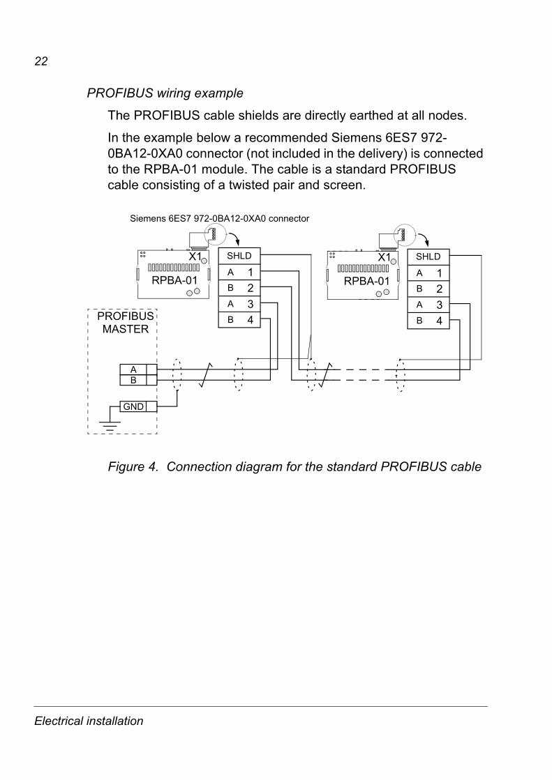
PROFIBUS wiring example
The PROFIBUS cable shields are directly earthed at all nodes.
In the example below a recommended Siemens 6ES7 972-0BA12-0XA0 connector (not included in the delivery) is connected to the RPBA-01 module. The cable is a standard PROFIBUS cable consisting of a twisted pair and screen.
Figure 4. Connection diagram for the standard PROFIBUS cable
X1
4321
A
B
AB
SHLD
PROFIBUS
RPBA-01
X1
4321
MASTER
BA
A
B
AB
GND
SHLD
RPBA-01
Siemens 6ES7 972-0BA12-0XA0 connector
Electrical installation

23
Programming
OverviewThis chapter gives information on configuring the PROFIBUS master station and the drive for communication through the RPBA-01 PROFIBUS-DP Adapter module.
Configuring the systemAfter the RPBA-01 PROFIBUS-DP Adapter module has been mechanically and electrically installed according to the instructions in previous chapters, the master station and the drive must be prepared for communication with the module.
The type definition (GSD) file required for configuration of the master station is available from www.profibus.com or your local ABB representative. The filename is ABB_0812.GSD.
Please refer to the master station documentation for more information.
PROFIBUS connection configurationThe detailed procedure of activating the module for communication with the drive is dependent on the drive type. (Normally, a parameter must be adjusted to activate the communication. See the drive documentation.)
As communication between the drive and the RPBA-01 is established, several configuration parameters are copied to the drive. These parameters – shown below in Table 5 – must be checked first and adjusted if necessary. The alternative selections for these parameters are discussed in more detail below the table.
Note: The new settings take effect only when the module is powered up the next time or when the module receives a ‘Fieldbus Adapter parameter refresh’ command from the drive.
Programming

24
Data transfer rates supported
The RPBA-01 supports the following PROFIBUS communication speeds: 9.6 kbit/s, 19.2 kbit/s, 45.45 kbit/s, 93.75 kbit/s, 187.5 kbit/s, 500 kbit/s, 1.5 Mbit/s, 3 Mbit/s, 6 Mbit/s, 12 Mbit/s.
The RPBA-01 automatically detects the communication speed and PPO-type used.
Table 5. The RPBA-01 configuration parameters.
Par. no.
Parameter name Alternative settings Defaultsetting
1 MODULE TYPE (Read-only) PROFIBUS-DP
2 Node address 0 to 126 3
3 Baud rate (12000) 12 Mbit/s; (6000) 6 Mbit/s; (3000) 3 Mbit/s; (1500) 1.5 Mbit/s; (500) 500 kbit/s; (187) 187.5 kbit/s; (93) 93.75 kbit/s; (45) 45.45 kbit/s; (19) 19.2 kbit/s; (9) 9.6 kbit/s 1)
1500
4 PPO-type (1) PPO 1; (2) PPO 2; (3) PPO 3;(4) PPO 4; (5) PPO 5; (Read-only) 1)
(1) PPO 1
5 PZD3 OUT 0 to 32767 with format xxyy, where xx = Parameter Group and yy = Parameter Index. See description below.
0
6 PZD3 IN See PZD3 OUT above 0
7 PZD4 OUT See PZD3 OUT above 0
8 PZD4 IN See PZD3 OUT above 0
... ... 19 PZD10 OUT See PZD3 OUT above 0
20 PZD10 IN See PZD3 OUT above 01) The value is automatically updated (Read-only).
Programming

25
Note: Set also the extended Parameter Data (see page 31) to ensure proper operation of the RPBA-01 with the drive.
1 MODULE TYPE
This parameter shows the module type as detected by the drive. The value cannot be adjusted by the user.
If this parameter is undefined, the communication between the drive and the module has not been established.
2 Node address
Each device on the PROFIBUS network must have a unique node number. This parameter is used to define a node number for the drive it is connected to, if the node address selection switches are set to the zero position. When the node address selector switches are used to define the node address (node address selectors not in zero position) this parameter indicates the set node address.
3 Baud rate
The speed of communication. The value is given in kbit/s:
4 PPO-type
This parameter indicates the selected PPO message type for the PROFIBUS communication. See Figure 6 in chapter Communication for the supported PPO message types.
12000 = 12 Mbit/s 6000 = 6 Mbit/s 3000 = 3 Mbit/s 1500 = 1.5 Mbit/s 500 = 500 kbit/s 187 = 187.5 kbit/s
93 = 93.75 kbit/s 45 = 45.45 kbit/s 19 = 19.2 kbit/s 9 = 9.6 kbit/s
Programming

26
5 PZD3 OUT
This parameter represents process data word 3 of the PPO type received by the drive over the PROFIBUS network. The content is defined by a decimal number in the range of 0 to 32767 as follows:
The parameter area is allocated as follows:
Parameter number with format xxyy, where xx is the parameter group number (1 to 99) and yy is the parameter number index inside the group (01 to 99).
0 not used
1 - 99 data set area of the drive
101 - 9999 parameter area of the drive
10000 - 32767 not supported by the drive
The data set area is allocated as follows:
1 data set 1 word 1
2 data set 1 word 2
3 data set 1 word 3
4 data set 2 word 1
5 data set 2 word 2
6 data set 2 word 3
7 data set 3 word 1
...99 data set 33 word 3
Programming

27
6 PZD3 IN
Process data word 3 of the PPO type sent from the drive to the PROFIBUS network.
The content is defined by a decimal number in the range of 0 to 32767. See parameter PZD3 OUT for description of decimal number allocation.
7 to 20 PZD4 OUT to PZD10 IN
See parameters PZD3 OUT and PZD3 IN.
Control locationsABB drives can receive control information from multiple sources including digital inputs, analogue inputs, the drive control panel and a communication module (e.g. RPBA-01). ABB drives allow the user to separately determine the source for each type of control information (Start, Stop, Direction, Reference, Fault Reset, etc.). In order to give the fieldbus master station the most complete control over the drive, the communication module must be selected as source for this information. See the user documentation of the drive for information on the selection parameters.
Programming

28
Programming
29
Communication
OverviewThis chapter describes the PROFIBUS messaging used in the communication with the drive.
PROFIBUS-DPThe RPBA-01 module supports the PROFIBUS-DP protocol according to EN 50170 standard. PROFIBUS-DP is a distributed I/O system which enables the master to use a large number of peripheral modules and field devices. The data transfer is mainly cyclic: the master reads the input information from the slaves and sends the output information back to the slaves.
The PROFIBUS-DP protocol uses so-called PPOs (Parameter/Process Data Objects) in cyclic communication. See Figure 6 for the different PPO types and their composition.
Service Access PointsThe services of the PROFIBUS Data Link Layer (Layer 2) are used by PROFIBUS-DP through Service Access Points (SAPs). Precisely defined functions are assigned to individual SAPs.
For further information on Service Access Points, refer to the manual of the PROFIBUS master, PROFIDRIVE – The PROFIBUS Profile for Adjustable Speed Drives, or the EN 50170 standard.
Communication

30
Communication start-upThe following Service Access Points (SAPs) are used to initiate DP communication:
SAP 61 (Set_Prm)
This SAP is used in the parameterisation of the drive.
SAP no. Short Name Name
61 Set_Prm Send Parameter Data
62 Chk_Cfg Check Configuration Data
60 Slave_Diag Read Slave Diagnostic
128 Data_Exch Transfer Input and Output Data
Prm_Data (Parameter Data Standard)Type: Octet String - Length: 8
Byte Value Description0 B8h Station_Status
1 - 2 Watchdog Factors 1 and 2 (set by the PROFIBUS master)WdFactor1 × WdFactor2 × 10 ms = monitoring time of the slave to verify that the master is still active.
3 0Bh Minimum Station Delay Respond TimeTime after which a slave station is allowed to send response frames to the master. Calculated by multiplying the Hex value with tBit (time required for transmitting one bit).
4 - 5 0812h Vendor Identification (for the RPBA-01: 0812h)6 00h Group Identification7 - Reserved
Reserved
Sync_Req
Unlock_Req
Lock_Req
Freeze_Req1 = Slave is requested to process in freeze mode
WD_On1 = Watchdog on
1 0 1 1 1 0 0 0
00 = Min TSDR and slave-related parameters may be overwritten10 = Slave locked for other masters. All parameters can be carried overx1 = Slave released for other masters
1 = Slave is requested to process in SYNC mode
Communication

31
Prm_Data (Parameter Data Extended)Type: Octet String - Length: 23
8 10h (default)
Header byte
9 - 10 0-65536 Cut off time out in milliseconds.
11 - 12 0-65536 Fail-safe, PZD1 (CW)
13 - 14 0-65536 Fail-safe, PZD2 (REF)
15 - 16 0-65536 Fail-safe, PZD3
17 - 18 0-65536 Fail-safe, PZD4
19 - 20 0-65536 Fail-safe, PZD5
21 - 22 0-65536 Fail-safe, PZD6
23 - 24 0-65536 Fail-safe, PZD7
25 - 26 0-65536 Fail-safe, PZD8
0 0 0 1 0 0 0 0
Fail-safe mode. Defines the action taken when the PLC is switched from ‘RUN’ to ‘STOP’ mode.00 = STOP (default)01 = LAST SPEED02 = USE FAIL-SAFE. The values of the PZDs are
defined by bytes 11-30 in the Prm_Data telegram.
Control zero mode. Defines the action taken if a PROFIBUS telegram containing only zeros is received.00 = USE FRAME (default). Note that, with this setting,
the drive might not be stopped (if it is running) since also bit 10 (Remote Command) in the control word is zero. However, the other PZD’s may still be updated, but have the value zero.
01 = IGNORE
Operation mode. Determines which control/status word and reference/actual values are used.00 = PROFIDRIVE (i.e. Generic drive profile)01 = VENDOR SPECIFIC (i.e. ABB Drives profile)
(default). With this setting,• Fail-safe mode ‘STOP’ equals ‘LAST SPEED’• the control word is forwarded unchanged to the
drive• if the drive has a parameter for selection of
operation mode (i.e. communication profile), make sure that the operation modes of the RPBA-01 and the drive match.
Reserved
Communication

32
The extended Parameter Data bytes are configured via the PROFIBUS network configuration tool. The functions are defined in the GSD file.
SAP 62 (Chk_Cfg)
SAP 62 selects the PPO type to be used. The table below gives the Hex frame that must be sent to the drive to select the PPO type.
27 - 28 0-65536 Fail-safe, PZD9
29 - 30 0-65536 Fail-safe, PZD10
Cfg_Data (Configuration Data)Type: Octet String - Length: 1 to 32
PPO Type Hex Frame
1 F3 F12 F3 F53 F14 F55 F3 F9
Communication
33
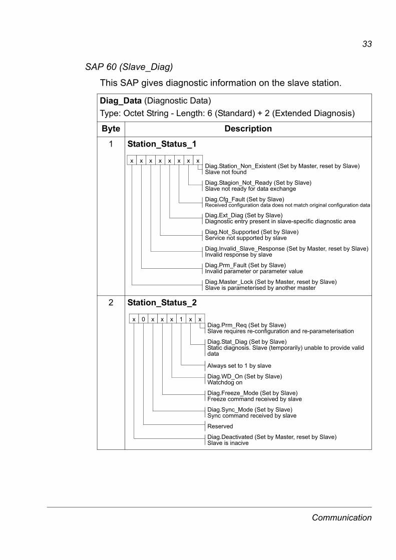
SAP 60 (Slave_Diag)
This SAP gives diagnostic information on the slave station.
Diag_Data (Diagnostic Data)Type: Octet String - Length: 6 (Standard) + 2 (Extended Diagnosis)
Byte Description1 Station_Status_1
2 Station_Status_2
x x x x x x x xDiag.Station_Non_Existent (Set by Master, reset by Slave)Slave not found
Diag.Stagion_Not_Ready (Set by Slave)Slave not ready for data exchange
Diag.Cfg_Fault (Set by Slave)Received configuration data does not match original configuration data
Diag.Ext_Diag (Set by Slave)Diagnostic entry present in slave-specific diagnostic area
Diag.Not_Supported (Set by Slave)Service not supported by slave
Diag.Invalid_Slave_Response (Set by Master, reset by Slave)Invalid response by slave
Diag.Prm_Fault (Set by Slave)Invalid parameter or parameter value
Diag.Master_Lock (Set by Master, reset by Slave)Slave is parameterised by another master
x 0 x x x 1 x xDiag.Prm_Req (Set by Slave)Slave requires re-configuration and re-parameterisation
Diag.Stat_Diag (Set by Slave)Static diagnosis. Slave (temporarily) unable to provide validdata
Always set to 1 by slave
Diag.WD_On (Set by Slave)Watchdog on
Diag.Freeze_Mode (Set by Slave)Freeze command received by slave
Diag.Sync_Mode (Set by Slave)Sync command received by slave
Reserved
Diag.Deactivated (Set by Master, reset by Slave)Slave is inacive
Communication
34
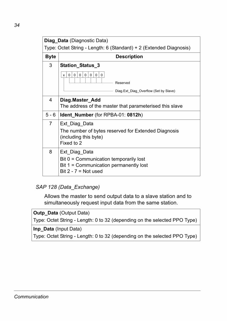
SAP 128 (Data_Exchange)
Allows the master to send output data to a slave station and to simultaneously request input data from the same station.
3 Station_Status_3
4 Diag.Master_AddThe address of the master that parameterised this slave
5 - 6 Ident_Number (for RPBA-01: 0812h)
7 Ext_Diag_DataThe number of bytes reserved for Extended Diagnosis (including this byte)Fixed to 2
8 Ext_Diag_DataBit 0 = Communication temporarily lostBit 1 = Communication permanently lostBit 2 - 7 = Not used
Outp_Data (Output Data)Type: Octet String - Length: 0 to 32 (depending on the selected PPO Type)
Inp_Data (Input Data)Type: Octet String - Length: 0 to 32 (depending on the selected PPO Type)
Diag_Data (Diagnostic Data)Type: Octet String - Length: 6 (Standard) + 2 (Extended Diagnosis)
Byte Description
Diag.Ext_Diag_Overflow (Set by Slave)
Reserved
x 0 0 0 0 0 0 0
Communication

35
PPO message types
Figure 6. PPO message types
Type 1
Type 2
Type 3
Type 4
Type 5
Parameter Process data
CW REF PZD3 PZD4 PZD5 PZD6 PZD7 PZD8 PZD9 PZD10VALUEIND
identification
PZD3SW ACT PZD4 PZD5 PZD6 PZD7 PZD8 PZD9 PZD10
Fixed area Freely mappable areaDW1.1 DW1.2 DW1.3 DW3.1 DW3.2 DW3.3 DW5.1 DW5.2 DW5.3 DW7.1
DW2.1 DW2.2 DW2.3 DW4.1 DW4.2 DW4.3 DW6.1 DW6.2 DW6.3 DW8.1
OUT area – Data sent from Master to Slave (control data)IN area – Data sent from Slave to Master (actual data)
Parameter Identification:ID – Parameter IdentificationIND – Index for ArraysVALUE – Parameter Value (Max. 4 bytes)
Process Data:CW – Control Word (see Table 7.)SW – Status Word (see Table 8.)REF – ReferenceACT – Actual ValuePZD – Process Data (application-specific) DS – Data SetDW – Data Word
OUT areaIN area ID IND VALUE
Communication

36
The Control Word and the Status WordThe Control Word (PROFIBUS Parameter 967) is the principal means for controlling the drive from a fieldbus system. It is sent by the fieldbus master station to the drive, the adapter module acting as a gateway. The drive switches between its states according to the bit-coded instructions on the Control Word, and returns status information to the master in the Status Word (PROFIBUS Parameter 968).
The contents of the Control Word and the Status Word are detailed in Tables 7 and 8 respectively; see the drive documentation for information on the drive-specific bits. The drive states are presented in the PROFIBUS State Machine (Figure 9).
ReferencesReferences are 16-bit words containing a sign bit and a 15-bit integer. A negative reference (indicating reversed direction of rotation) is formed by calculating the two’s complement from the corresponding positive reference.
ABB drives can receive control information from multiple sources including analogue and digital inputs, the drive control panel and a communication module (e.g. RPBA-01). In order to have the drive controlled through PROFIBUS, the communication module must be defined as the source for control information, e.g. Reference.
In the Vendor Specific mode, the scaling of the integer received from the master as Reference is drive-specific. See its programming manual for available control source selections and Reference scaling factors.
In PROFIdrive mode, the speed reference (REF) in hexadecimal (0…4000h) corresponds to 0…‘motor nominal speed’.
Actual ValuesActual Values are 16-bit words containing information on the operation of the drive. The functions to be monitored are selected by a drive parameter. The scaling of the integers sent to the
Communication

37
master as Actual Values depends on the selected function, refer to the drive documentation.
In PROFIdrive mode, the actual speed (ACT) in hexadecimal (0…4000h) corresponds to 0…‘motor nominal speed’.
Table 7. The Control Word (PROFIBUS Parameter 967). The upper case boldface text refers to the states shown in Figure 9.
Bit Name Value Proceed to STATE/Description0 ON 1 Proceed to READY TO OPERATE
OFF1 0 Emergency OFF, stop by the selected deceleration ramp. Proceed to OFF1 ACTIVE; proceed further to READY TO SWITCH ON unless other interlocks (OFF2, OFF3) are active
1 OFF2 1 Continue operation (OFF2 inactive)
0 Emergency OFF, coast to stop.Proceed to OFF2 ACTIVE; proceed further to SWITCH-ON INHIBIT
2 OFF3 1 Continue operation (OFF3 inactive)
0 Emergency stop, stop according to fastest possible deceleration mode. Proceed to OFF3 ACTIVE; proceed further to SWITCH-ON INHIBIT. Warning: Ensure motor and driven machine can be stopped using this stop mode.
3 OPERATION_ENABLE
1 Proceed to ENABLE OPERATION0 Inhibit operation. Proceed to OPERATION INHIBIT
4 RAMP_OUT_ZERO
1 Normal operation.Proceed to RAMP FUNCTION GENERATOR: ENABLE OUTPUT
0 Stop according to selected stop type
5 RAMP_HOLD 1 Normal operation.Proceed to RAMP FUNCTION GENERATOR: ENABLE ACCELERATOR
0 Halt ramping (Ramp Function Generator output held)
Communication

38
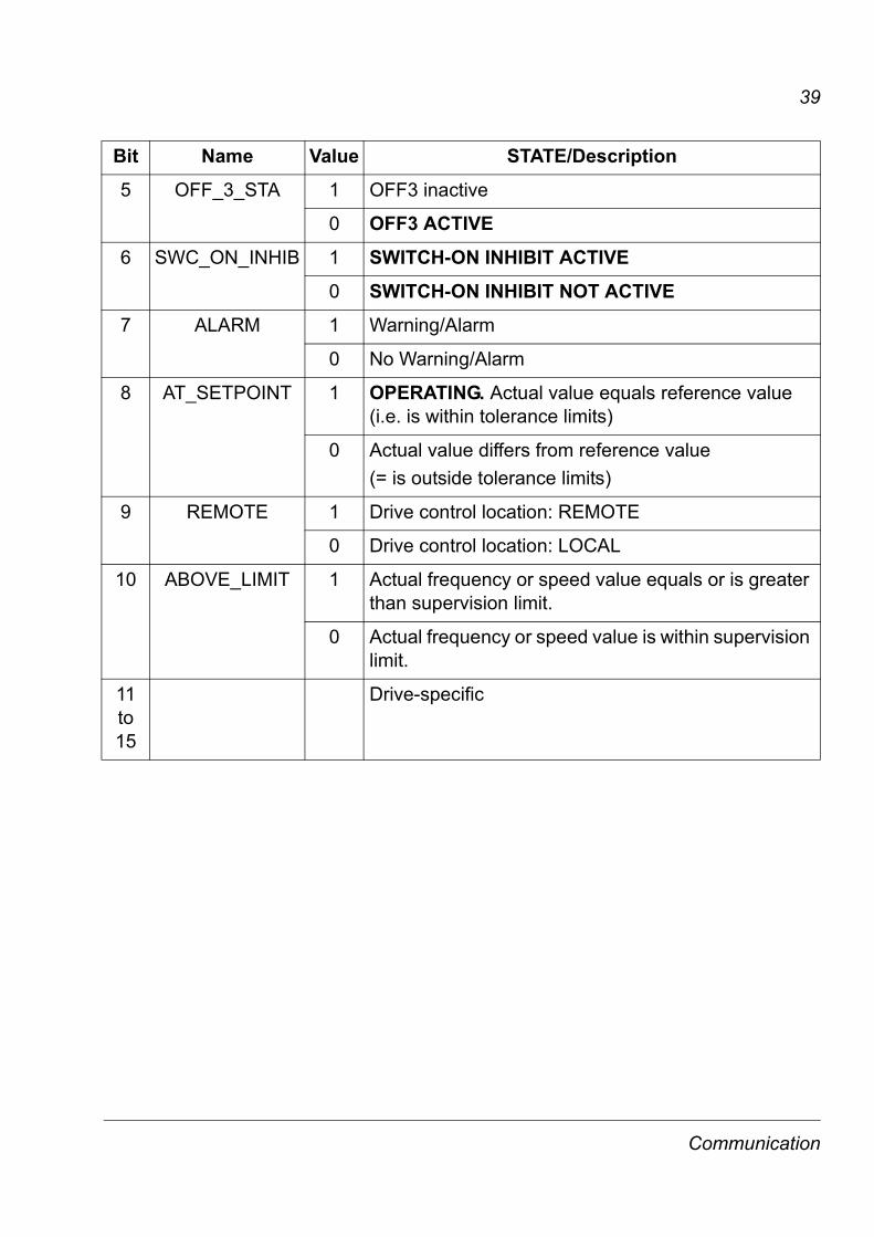
Table 8. The Status Word (PROFIBUS Parameter 968). The upper case boldface text refers to the states shown in Figure 9.
6 RAMP_IN_ZERO
1 Normal operation. Proceed to OPERATING0 Force Ramp Function Generator input to zero
7 RESET 0 1 Fault reset if an active fault exists. Proceed to SWITCH-ON INHIBIT.
0 (Continue normal operation)
8 INCHING_1 Inching 1. (See the drive documentation for information)
9 INCHING_2 Inching 2. (See the drive documentation for information)
10 REMOTE_CMD
1 Fieldbus control enabled
0 Control Word <> 0 or Reference <> 0: Retain last Control Word and ReferenceControl Word = 0 and Reference = 0: Fieldbus control enabled
11 to 15
Drive-specific. (See the drive documentation for information)
Bit Name Value STATE/Description0 RDY_ON 1 READY TO SWITCH ON
0 NOT READY TO SWITCH ON1 RDY_RUN 1 READY TO OPERATE
0 OFF1 ACTIVE2 RDY_REF 1 ENABLE OPERATION
0 DISABLE OPERATION3 TRIPPED 1 FAULT
0 No fault
4 OFF_2_STA 1 OFF2 inactive
0 OFF2 ACTIVE
Bit Name Value Proceed to STATE/Description
Communication
39
5 OFF_3_STA 1 OFF3 inactive
0 OFF3 ACTIVE6 SWC_ON_INHIB 1 SWITCH-ON INHIBIT ACTIVE
0 SWITCH-ON INHIBIT NOT ACTIVE7 ALARM 1 Warning/Alarm
0 No Warning/Alarm
8 AT_SETPOINT 1 OPERATING. Actual value equals reference value (i.e. is within tolerance limits)
0 Actual value differs from reference value (= is outside tolerance limits)
9 REMOTE 1 Drive control location: REMOTE
0 Drive control location: LOCAL
10 ABOVE_LIMIT 1 Actual frequency or speed value equals or is greater than supervision limit.
0 Actual frequency or speed value is within supervision limit.
11 to 15
Drive-specific
Bit Name Value STATE/Description
Communication

40
Figure 9. The PROFIBUS state machine
‘n=0 or f =0’ and ‘I=0’and inching pause expired
Inching 1 or 2 OFF(CW Bit8=0 or Bit9=0)
MAINS OFF
Power ON OFF1 (CW Bit0=0)
SWITCH-ONINHIBIT (SW Bit6=1)
NOT READYTO SWITCH ON (SW Bit0=0)
READY TOSWITCH ON
from any state
(CW=xxxx xxxx xxxx x110)
PROFIBUSState Machine
READY TOOPERATE (SW Bit1=1)
n(f)=0 / I=0
OPERATIONINHIBIT (SW Bit2=0)
A B C D
(CW Bit3=0)
operationinhibited
OFF1 (CW Bit0=0)
OFF1ACTIVE (SW Bit1=0)
(SW Bit0=1)
(CW Bit3=1)
C D
(CW Bit5=0)
OPERATIONENABLE
(SW Bit2=1)
(SW Bit5=0)
from any state from any stateEmergency StopOFF3 (CW Bit2=0)
n(f)=0 / I=0
OFF3ACTIVE
Emergency StopOFF2 (CW Bit1=0)
(SW Bit4=0)OFF2
ACTIVE
RFG: ENABLEOUTPUT
RFG: ENABLEACCELERATION
OPERATING
B
B C D
(CW Bit4=0)
(CW Bit4=1)
(CW Bit5=1)
D
(CW Bit6=0)
A
C(CW Bit6=1)
(SW Bit8=1)D
from any state
Fault
(SW Bit3=1)FAULT
(CW Bit7=1)
ON (CW=xxxx xxxx xxxx x111)
CW = Control WordSW = Status Wordn = SpeedI = Input CurrentRFG = Ramp Function
Generatorf = Frequency
state
condition
rising edgethe bitof
INCHING 1
ACTIVE
Inching 1 or 2 ON(CW Bit4=0 Bit5=0 Bit6=0)
Enable operation
Main contactor ON
Main contactor OFF
(CW Bit8=1 or Bit9=1)
orINCHING 2
Inching pause
Communication

41
Parameter handling in cyclic communication (DP)In cyclic PROFIBUS-DP communication, parameter data is transferred in PPO message types 1, 2 and 5 (see Figure 6.). The Parameter Identification part consists of eight bytes (see below).
The Request Label is used by the master when transmitting data to the slave, while the Response Label is used by the slave as a positive or negative acknowledgement. The tables below show the Request/Response functions.
Request labels (from Master to Slave)Request Function Response labels
Ackn. (+) Ackn. (-)0 No task 0 –1 Request parameter value 1, 2 72 Change parameter value (word) 1 7, 83 Change parameter value (double word) 2 7, 84 Request description element 3 75 Change description element 3 7, 86 Request parameter value (array) 4, 5 7, 87 Change parameter value (array word) 4 7, 88 Change parameter value (array double word) 5 7,89 Request number of array elements 6 7
ID IND VALUE
15 14 13 12 11 10 9 8 7 6 5 4 3 2 1 0
Request LabelResponse Label
*Request Signal
Parameter Number (PNU)
Process DataParameter
Identification
*Not used (=0)
CW REF(PD1, PD2...)SW ACT
Communication
42
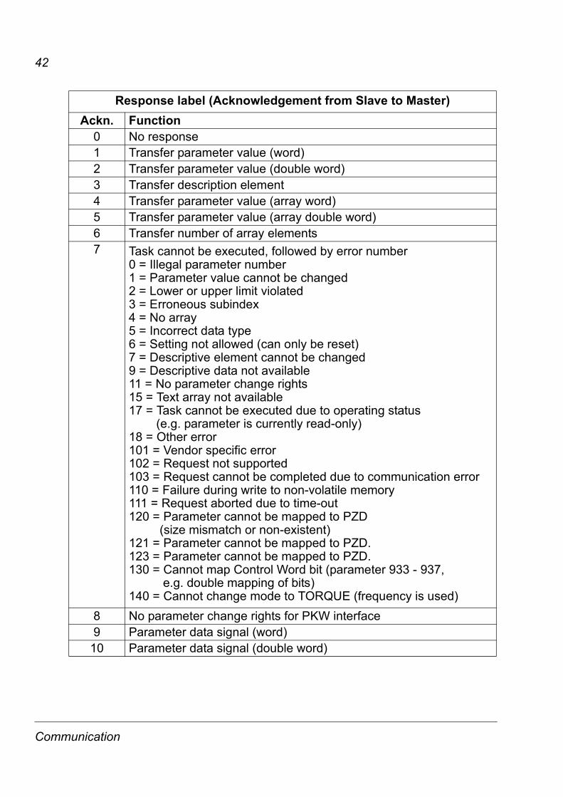
Response label (Acknowledgement from Slave to Master)Ackn. Function
0 No response1 Transfer parameter value (word)2 Transfer parameter value (double word)3 Transfer description element4 Transfer parameter value (array word)5 Transfer parameter value (array double word)6 Transfer number of array elements7 Task cannot be executed, followed by error number
0 = Illegal parameter number1 = Parameter value cannot be changed2 = Lower or upper limit violated3 = Erroneous subindex4 = No array5 = Incorrect data type6 = Setting not allowed (can only be reset)7 = Descriptive element cannot be changed9 = Descriptive data not available11 = No parameter change rights15 = Text array not available17 = Task cannot be executed due to operating status (e.g. parameter is currently read-only)18 = Other error101 = Vendor specific error102 = Request not supported103 = Request cannot be completed due to communication error110 = Failure during write to non-volatile memory111 = Request aborted due to time-out120 = Parameter cannot be mapped to PZD (size mismatch or non-existent)121 = Parameter cannot be mapped to PZD.123 = Parameter cannot be mapped to PZD.130 = Cannot map Control Word bit (parameter 933 - 937, e.g. double mapping of bits)140 = Cannot change mode to TORQUE (frequency is used)
8 No parameter change rights for PKW interface9 Parameter data signal (word)10 Parameter data signal (double word)
Communication
43
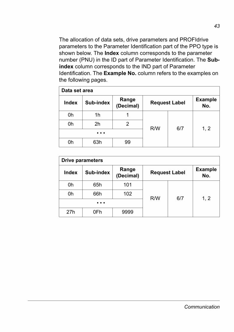
The allocation of data sets, drive parameters and PROFIdrive parameters to the Parameter Identification part of the PPO type is shown below. The Index column corresponds to the parameter number (PNU) in the ID part of Parameter Identification. The Sub-index column corresponds to the IND part of Parameter Identification. The Example No. column refers to the examples on the following pages.
Data set area
Index Sub-index Range (Decimal) Request Label Example
No.0h 1h 1
R/W 6/7 1, 20h 2h 2
• • •
0h 63h 99
Drive parameters
Index Sub-index Range (Decimal) Request Label Example
No.0h 65h 101
R/W 6/7 1, 20h 66h 102
• • •
27h 0Fh 9999
Communication

44
The complete PROFIdrive parameter list for the RPBA-01 can be found as a separate chapter elsewhere in this manual.
Note: Continuous (cyclic) writing of PROFIdrive parameters should be avoided as the values of these parameters are stored in the flash memory of the RPBA-01. The estimated lifetime of the flash memory is 1,000,000 program/erase cycles, and continuous writing will cause the memory to fail prematurely.
PROFIdrive parameters
Index Sub-index Range (Decimal) Request Label Example
No.
393h
2h
915
2
R/W 6/7 63h 3
• • • • • •
9h 9
394h
2h
916
2
R/W 6/7 73h 3
• • • • • •
9h 9
396h 0h 918 R/W 1/2 3, 4
• • •
3B3h
0h
947
1
R 6 5
9h 9
11h 17
19h 25
21h 33
29h 41
• • •
3CCh 0h 972 R/W 1/2 3,4
Communication

45
Example 1: Reading a drive parameter (or data set)
To determine the parameter number and subindex for drive parameter reading, multiply the parameter number by one hundred and then convert it to hexadecimal. The low byte is the subindex (IND), and the high byte is the parameter number (PNU). For example reading parameter 84.11 INPUT 1 from the drive:84.11 × 100 = 8411 = 20DB Hex.Parameter number is 20 and subindex is DB.
Req 60 20 DB 00 00 00 00 00 04 7F 34 15 00 00 00 00 00 00 00 00
Resp 60 20 DB 00 00 00 00 64 03 37 34 15 00 00 00 00 00 00 00 00
CW REF
Parameter Number (20 Hex)Request (Read parameter value [array])
Subindex (DB Hex)*
PZD3 PZD4 PZD5 PZD6
SW ACT PZD3 PZD4 PZD5 PZD6Parameter Value (100 Dec)
Parameter Number (20 Hex)Response (Change parameter value [array])
Subindex (DB Hex)*
*2nd byte reserved
Communication

46
Example 2: Writing a drive parameter (or data set)
To determine the parameter number and subindex for drive parameter writing, multiply the parameter number by one hundred and then convert it to hexadecimal. The low byte is the subindex (IND), and the high byte is the parameter number (PNU). For example write parameter 12.02 CONSTANT SPEED.1: 12.02 × 100 = 1202 = 04B2 Hex. Parameter is 04 and subindex is 2B.
Req 70 04 B2 00 00 00 00 64 04 7F 34 15 00 00 00 00 00 00 00 00
Resp 40 04 B2 00 00 00 00 64 03 37 34 15 00 00 00 00 00 00 00 00
Parameter Value (100 Dec)CW REF
Parameter Number (04 Hex)Request (Change parameter value [array])
Subindex (B2 Hex)*
PZD3 PZD4 PZD5 PZD6
SW ACT PZD3 PZD4 PZD5 PZD6Parameter Value (100 Dec)
Parameter Number (04 Hex)Response (Transfer parameter value [array])
Subindex (B2 Hex)*
*2nd byte reserved
Communication

47
Example 3: Reading a PROFIdrive parameter (word)
In this example, PROFIBUS Parameter No. 918 is used to read the station number of the slave.
The slave returns its station number (2).
Read:Request 13 96 00 00 00 00 00 00 04 7F 34 15
Response 13 96 00 00 00 00 00 02 03 37 34 15
Param. Value CW REFIND
Parameter Number (918 Dec)
Request (Parameter value read)
Response (Parameter value updated)
Parameter Number (918 Dec)
IND Param. Value SW ACT
Communication

48
Example 4: Writing a PROFIdrive parameter (word)
In this example, current parameter settings are saved to the FLASH memory of the drive. This is done by setting the value of PROFIBUS Parameter No. 971 (3CBh) to 1.
Note that the drive always observes the Control Word (CW) and Reference (REF) bytes. The values shown below are examples.
Write:Request 23 CB 00 00 00 00 00 01 04 7F 34 15
Response 13 CB 00 00 00 00 00 00 03 37 34 15
Param. Value CW REFIND
Parameter Number (971 Dec)
Request (Parameter value write)
Response (Parameter value updated)
Parameter Number (971 Dec)
IND Param. Value SW ACT
Communication

49
Example 5: Reading a PROFIdrive parameter (array)
In this example, PROFIBUS Parameter No. 947 is used to read the code of the latest acknowledged fault. As shown in Table 10 on page 57, parameter 945 is of the array type with subindexes 1, 9, 17 and 25.
The slave returns the code of the latest acknowledged fault (2300h). The fault codes are according to the DRIVECOM standard. See also the User’s Manual of the drive for drive specific fault codes.
The implementation of the PROFIdrive profile in the RPBA-01 supports the storage of the active and the five latest occurred different faults in the fault buffer. The fault codes can be accessed by PROFIdrive parameters 945, 947 and 948 (see Table 10 on page 55). The value zero indicates no fault. The subindexes of these parameters are related to each other, i.e. parameter 945 with subindex 1 relates to subindex of parameter 947 and 948. For an explanation on the subindexes, refer to Table 10 on page 55.
Read:Request 63 B1 09 00 00 00 00 00 04 7F 34 15
Response 43 B1 09 00 00 00 23 00 03 37 34 15
Param. Value CW REF
Parameter Number (945 Dec)
Request (Request parameter value [array])
Subindex (Latest acknowledged fault)*
Response (Transfer parameter value [array])
Parameter Number (945 Dec)
Param. Value SW ACT
Subindex (Latest acknowledged fault)*
*2nd byte reserved
Communication

50
Example 6: Configuring the process data written to the drive
PROFIBUS parameter 915 can be used to define which data is written cyclically to a drive parameter as application-specific process data.
In the example below, the value of drive parameter 12.02 CONSTANT SPEED 1 (4B2h) is selected to be taken from PZD3. The parameter will continue to be updated with the contents of PZD3 in each Request frame until a different selection is made.
Subindex (IND) defines which process data word the required data is taken from. Parameter Value selects the drive parameter to which that word is mapped.
Subsequently, the contents of PZD3 in each Request frame are written to drive parameter 12.02 CONSTANT SPEED 1 until a different selection is made.
Req 73 93 03 00 00 00 04 B2 04 7F 34 15 00 00 00 00 00 00 00 00
Resp 43 93 03 00 00 00 04 B2 03 37 34 15 00 00 00 00 00 00 00 00
Parameter Value (104 Dec)CW REF
Parameter Number (915 Dec)Request (Change parameter value [array])
Subindex (03 = PZD3)*
PZD3 PZD4 PZD5 PZD6
SW ACT
*2nd byte reserved
PZD3 PZD4 PZD5 PZD6Parameter Value (104 Dec)
Parameter Number (915 Dec)Response (Transfer parameter value [array])
Subindex (03 = PZD3)*
Communication

51
Example 7: Configuring the process data read from the drive
PROFIBUS Parameter No. 916 can be used to define which data is read cyclically from the drive as application-specific process data.
In the example below, drive parameter 1.04 CURRENT (68h) is selected to be transmitted by the drive as PZD3. The selection is in force until it is superseded by another selection.
Subindex (IND) defines which process data word the required data is transmitted in, and Parameter Value defines which drive parameter is mapped to that word.
Subsequent response frames:
Req 73 94 03 00 00 00 00 68 04 7F 34 15 00 00 00 00 00 00 00 00
Resp 43 94 03 00 00 00 00 68 03 37 34 15 00 00 00 00 00 00 00 00
Resp xx xx xx xx xx xx xx xx xx xx xx xx 00 0B xx xx xx xx xx xx
Parameter Value (104 Dec)CW REF
Parameter Number (916 Dec)Request (Change parameter value [array])
Subindex (03 = PZD3)*
PZD3 PZD4 PZD5 PZD6
SW ACT
*2nd byte reserved
PZD3 PZD4 PZD5 PZD6Parameter Value (104 Dec)
Parameter Number (916 Dec)Response (Transfer parameter value [array])
Subindex (03 = PZD3)*
PZD3 (Value of Drive Parameter 1.04)
Communication

52
Communication

53
Fault tracing
LED indicationsThe RPBA-01 module is equipped with three diagnostic LEDs. The description of the LEDs is below.
Name Colour Function
ERR
OR
Red
Flashing 1 Hz - Error in configuration: Internal configuration mismatch.Flashing 2 Hz - Error in User Parameter data: The length/contents of the User Parameter data set during initialisation of the module is not equal to the length/contents set during configuration of the network.Flashing 4 Hz - Error in initialisation of the PROFIBUS communication ASIC.Off - No diagnostics present
On-
Line
GreenLit - Module is On-Line and data exchange is possible.Off - Module is not On-Line
Off-
Line
RedLit - Module is Off-Line and no data exchange is possible.Off - Module is not Off-Line
Off-line
ERRORHost Indication
On-line
Fault tracing

54
Hos
t Ind
icat
ion
Green Lit - Link functional
RedLit - Link lost permanentlyFlashing - Link lost temporarily
Name Colour Function
Off-line
ERRORHost Indication
On-line
Fault tracing

55
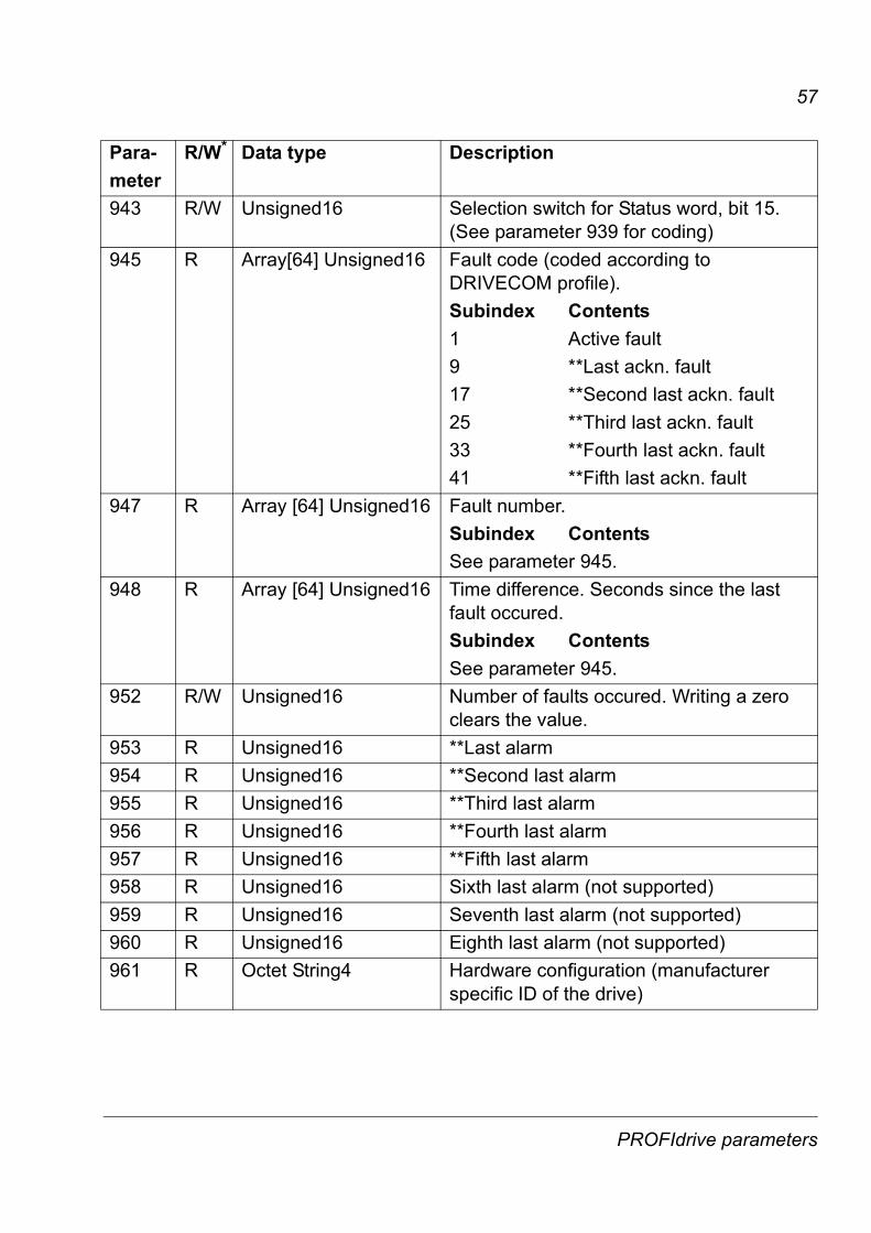
PROFIdrive parameters
Table 10. PROFIdrive profile-specific parameters.
Para-meter
R/W* Data type Description
915 R/W Array [10] Unsigned16 Assignment PZD1 to PZD10 in PPO-write916 R/W Array [10] Unsigned16 Assignment PZD1 to PZD10 in PPO-read918 R/W Unsigned16 Node address. Writing this parameter will
change the node address if the rotary switches have the setting 0. Module re-start required.
919 R Octet String4 Device system number.927 R/W Unsigned16 Operator control rights (parameter
identification, PKW).Value Mode0 Parameters cannot be
written, only read (927 can be written)
1 Parameters can be written and read (default).
928 R/W Unsigned16 Control rights (process data, PZD).Value Mode0 PZD part is disabled, i.e.
Receipt of new PZD data is ignored
1 PZD part is enabled (default).
929 R Unsigned16 Selected PPO-typeValue PPO-type Configuration1 PPO1 F3h, F1h2 PPO2 F3h, F5h3 PPO3 F1h4 PPO4 F5h5 PPO5 F3h, F9h
PROFIdrive parameters
56
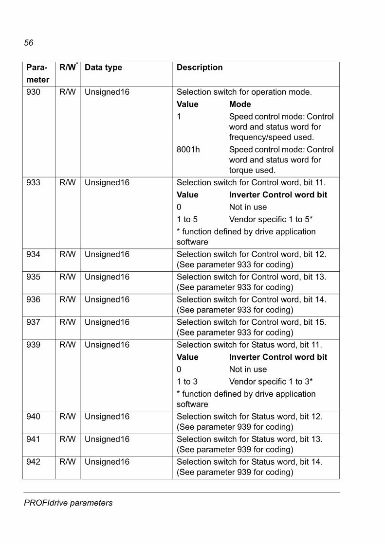
930 R/W Unsigned16 Selection switch for operation mode.Value Mode1 Speed control mode: Control
word and status word for frequency/speed used.
8001h Speed control mode: Control word and status word for torque used.
933 R/W Unsigned16 Selection switch for Control word, bit 11.Value Inverter Control word bit0 Not in use1 to 5 Vendor specific 1 to 5** function defined by drive application software
934 R/W Unsigned16 Selection switch for Control word, bit 12. (See parameter 933 for coding)
935 R/W Unsigned16 Selection switch for Control word, bit 13. (See parameter 933 for coding)
936 R/W Unsigned16 Selection switch for Control word, bit 14. (See parameter 933 for coding)
937 R/W Unsigned16 Selection switch for Control word, bit 15. (See parameter 933 for coding)
939 R/W Unsigned16 Selection switch for Status word, bit 11.Value Inverter Control word bit0 Not in use1 to 3 Vendor specific 1 to 3** function defined by drive application software
940 R/W Unsigned16 Selection switch for Status word, bit 12. (See parameter 939 for coding)
941 R/W Unsigned16 Selection switch for Status word, bit 13. (See parameter 939 for coding)
942 R/W Unsigned16 Selection switch for Status word, bit 14. (See parameter 939 for coding)
Para-meter
R/W* Data type Description
PROFIdrive parameters
57
943 R/W Unsigned16 Selection switch for Status word, bit 15. (See parameter 939 for coding)
945 R Array[64] Unsigned16 Fault code (coded according to DRIVECOM profile).Subindex Contents1 Active fault9 **Last ackn. fault17 **Second last ackn. fault25 **Third last ackn. fault33 **Fourth last ackn. fault41 **Fifth last ackn. fault
947 R Array [64] Unsigned16 Fault number. Subindex ContentsSee parameter 945.
948 R Array [64] Unsigned16 Time difference. Seconds since the last fault occured.Subindex ContentsSee parameter 945.
952 R/W Unsigned16 Number of faults occured. Writing a zero clears the value.
953 R Unsigned16 **Last alarm954 R Unsigned16 **Second last alarm955 R Unsigned16 **Third last alarm956 R Unsigned16 **Fourth last alarm957 R Unsigned16 **Fifth last alarm958 R Unsigned16 Sixth last alarm (not supported)959 R Unsigned16 Seventh last alarm (not supported)960 R Unsigned16 Eighth last alarm (not supported)961 R Octet String4 Hardware configuration (manufacturer
specific ID of the drive)
Para-meter
R/W* Data type Description
PROFIdrive parameters

58
963 R Unsigned16 Detected baud rate:0 = 12 Mbit/s1 = 6 Mbit/s2 = 3 Mbit/s3 = 1.5 Mbit/s4 = 500 kbit/s5 = 187.5 kbit/s6 = 93.75 kbit/s7 = 45.45 kbit/s8 = 19.2 kbit/s9 = 9.6 kbit/s255 = Invalid baud rate
964 R Unsigned16 Identification number of this device (0812h)
965 R Octet String2 Profile number of this device (0302h)Profile 3, Version 2
967 R Unsigned16 Control word (CW)968 R Unsigned16 Status word (SW)970 R/W Unsigned16 Load parameter record
Value Description0 No action1 Restore factory settingsThe parameter must do a zero-to-one transition and the motor must be stopped.
971 R/W Unsigned16 Save parameter recordValue Description0 No action1 Save the drive parameters
to non-volatile memoryThe parameter must do a zero-to-one transition and the motor must be stopped.
Para-meter
R/W* Data type Description
PROFIdrive parameters

59
972 R/W Unsigned16 Software resetValue Description0 No action1 Re-boot PROFIBUS moduleThe parameter must do a zero-to-one transition and the motor must be stopped.
* Read and/or Write** Support depends on drive type
Para-meter
R/W* Data type Description
PROFIdrive parameters

60
PROFIdrive parameters

61
Definitions and abbreviations
PROFIBUS definitionsAcyclic
CommunicationCommunication in which messages are sent only once on request
Array Parameter consisting of data fields of equal data type
Broadcast Non-acknowledged message from master to all bus participants (compare Multicast)
Command Word See Control Word
CommunicationObject
Any object of a real device that can be communicated with (variable, program, data range, etc.). Stored locally in the Object Dictionary.
Control Word 16-bit word from master to slave with bit-coded control signals (sometimes called the Command Word).
CyclicCommunication
Communication in which Parameter-/Process Data-Objects are sent cyclically at pre-defined intervals
Device Class Classification according to the number of profile functions included in the device
Drivecast Broad- and Multicast, a special message frame for drives
Fault Event that leads to tripping of the device
GSD File ASCII-format device description file in a specified form. Each device (active & passive stations) on PROFIBUS has to have its own GSD File.
Index Access reference for Objects in PROFIBUS
Information Report Non-acknowledged message from master to one or all groups of bus participants
Definitions and abbreviations

62
Master Control system with bus initiative. In PROFIBUS terminology, master stations are also called active stations.
Multicast Non-acknowledged message from master to one group of bus participants (compare Broadcast)
Name Symbolic name of a parameter
Nibble Set of 4 bits
Object Dictionary Local storage of all Communication Objects recognised by a device
Object List List of all accessible objects
Parameter Value that can be accessed as Object, e.g. variable, constant, signal
Parameter Number Parameter address
Parameter/ProcessData Object
Special object that contains Parameter and Process Data
Process Data Data that contains Control Word and Reference value or Status Word and Actual value. May also contain other (user-definable) control information.
Profile Adaptation of the protocol for certain application field, e.g. drives
Request Label Coded information specifying the required service for the parameter part sent from master to slave
Response Label Coded information specifying the required service for the parameter part sent from slave to master
Slave Passive bus participant. In PROFIBUS terminology, slave stations (or slaves) are also called passive stations. Also referred to as node.
Status Word 16-bit word from slave to master with bit-coded status messages
Definitions and abbreviations

63
Warning Signal caused by an existing alarm which does not lead to tripping of the device
PROFIBUS abbreviationsThe text in italics is the original German term.
.con Confirmation
.ind Indication
.req Request
.res Response
ACT Actual ValueIstwert
AK Request Label/Response LabelAuftragskennung/Antwortkennung
ALI Application Layer Interface
CR Communication ReferenceKommunikationsreferenz (Kommunikationsbeziehung)
DP Decentralised PeripheryDezentrale Peripherie
DP-ALI Application Layer Interface for DP
DPV1 PROFIBUS-DP Extensions to the EN 50170 standard,including e.g. acyclic data exchange
FDL Fieldbus Data Link
FMS Fieldbus Message Specification
FSU Manufacturer Specific InterfaceFirmenspezifischer Umsetzer
HIW Main Actual ValueHauptistwert
HSW Main ReferenceHauptsollwert
Definitions and abbreviations

64
ISW see ACT
KR (KB) see CR
PA Process AutomationProzessautomatisierung
PD Process DataProzessdaten
PKE Parameter IdentificationParameter-Kennung
PKW Parameter Identification ValueParameter-Kennung-Wert
PNU Parameter NumberParameternummer
PPO Parameter/Process Data ObjectParameter-/Prozessdaten-Objekt
PWE Parameter ValueParameter-Wert
PZD see PD
PZDO Process Data ObjectProzessdatenobjekt
SAP Service Access Point
SOW ReferenceSollwert
SPM Request SignalSpontanmeldung
STW Control WordSteuerwort
ZSW Status WordZustandswort
Definitions and abbreviations

65
Technical data
RPBA-01Enclosure:
Mounting: Into the option slot on the control board of the drive.
Degree of protection: IP 20
Ambient conditions: The applicable ambient conditions specified for the drive in its Hardware Manual are in effect.
Hardware settings: • Rotary switches for node address selection (address range
00 to 99)
• DIP switch for bus termination selection
Software settings:• Input/Output/User Parameter data/Diagnostics format
• Maximum cyclic I/O data size: 244 bytes in, max 244 bytes out, max. 416 bytes total
• Maximum User Parameter data/Diagnostics length: 237 bytes
95 m
m
34 mm
20 mm
62 mm
Technical data

66
Connectors:• 34-pin parallel bus connector
• 9-pin female DSUB connector
Current consumption:• 350 mA max. (5 V), supplied by the control board of the drive
General:• Estimated min. lifetime: 100 000 h
• All materials UL/CSA-approved
• Complies with EMC standards EN 50081-2 and EN 50082-2
Technical data

67
PROFIBUS linkCompatible devices: All devices compatible with the PROFIBUS-DP protocol
Size of the link: 127 stations including repeaters (31 stations and 1 repeater per segment)
Medium: Shielded, twisted pair RS-485 cable
• Termination: built in the module
• Specifications:
• Maximum bus length:
Topology: Multi-drop
Serial communication type: Asynchronous, half Duplex
Transfer rate: 9.6 kbit/s, 19.2 kbit/s, 45.45 kbit/s, 93.75 kbit/s, 187.5 kbit/s, 500 kbit/s, 1.5 Mbit/s, 3 Mbit/s, 6 Mbit/s, or 12 Mbit/s (automatically detected by RPBA-01)
Protocol: PROFIBUS-DP
Parameter Line APROFIBUS-DP
Line BDIN 19245 Part 1
Unit
Impedance 135 to 165(3 to 20 MHz)
100 to 130(f > 100 kHz)
W
Capacitance < 30 < 60 pF/m
Resistance < 110 – Ω/km
Wire gauge > 0.64 > 0.53 mm
Conductor area > 0.34 > 0.22 mm2
Transfer rate (kbit/s) ≤ 93.75 187.5 500 1500 3000 6000 12000
Line A (m) 1200 1000 400 200 100 100 100
Line B (m) 1200 600 200 – – – –
Technical data

68
Technical data


ABB OyAC DrivesP.O. Box 184FIN-00381 HELSINKIFINLANDTelephone +358 10 22 11Fax +358 10 22 22681Internet http://www.abb.com
ABB Inc.Automation TechnologiesDrives & Motors16250 West Glendale DriveNew Berlin, WI 53151USATelephone 262 785-3200
800-HELP-365Fax 262 780-5135
3AFE
645
0421
5 R
EV E
EN
EFFE
CTI
VE: 1
3.10
.200
3