User’s Manual Position Display Units for Milling Machines
56
9/2000 Position Display Units for Milling Machines User’s Manual
Transcript of User’s Manual Position Display Units for Milling Machines
9/2000
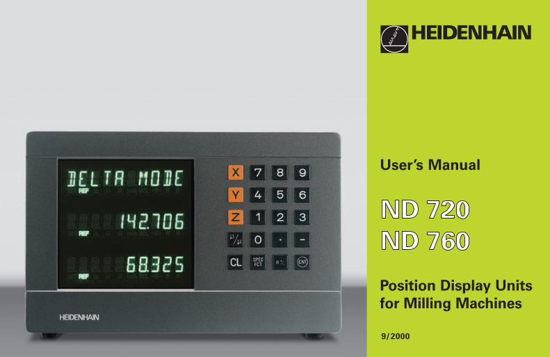
Position Display Units
for Milling Machines
User’s Manual
����������
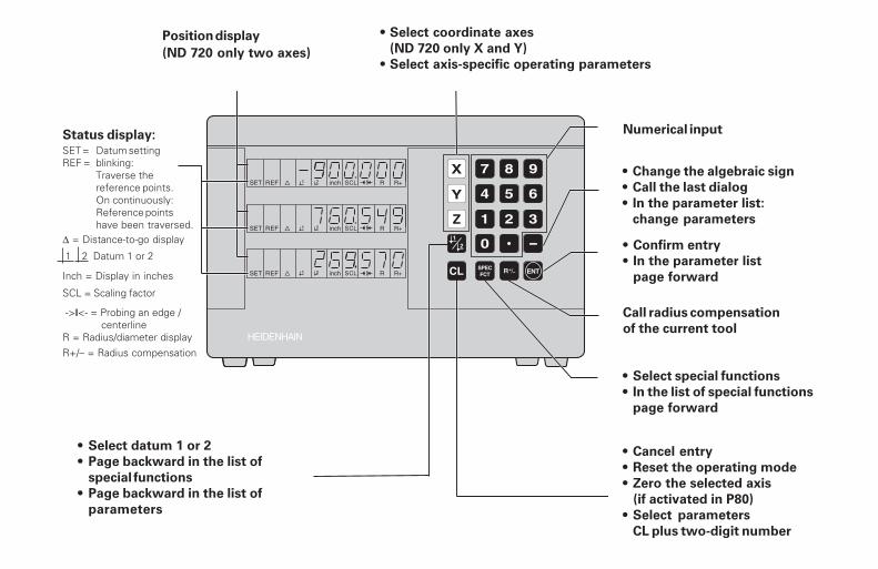
Position display
(ND 720 only two axes)
∆ = Distance-to-go display
R+/– = Radius compensation
Numerical input
• Change the algebraic sign
• Call the last dialog
• In the parameter list:
change parameters
Call radius compensation
of the current tool
• Select special functions
• In the list of special functions
page forward
• Cancel entry
• Reset the operating mode
• Zero the selected axis
(if activated in P80)
• Select parameters
CL plus two-digit number
Status display:
SCL = Scaling factor
->❘❘<- = Probing an edge / centerlineR = Radius/diameter display
• Select datum 1 or 2
• Page backward in the list of
special functions
• Page backward in the list of
parameters
1 2 Datum 1 or 2
SET = Datum settingREF = blinking:
Traverse thereference points.On continuously:Reference pointshave been traversed.
Inch = Display in inches
• Select coordinate axes
(ND 720 only X and Y)
• Select axis-specific operating parameters
• Confirm entry
• In the parameter list
page forward
Part
I O
pera
tin
g In
str
ucti
on
s
3
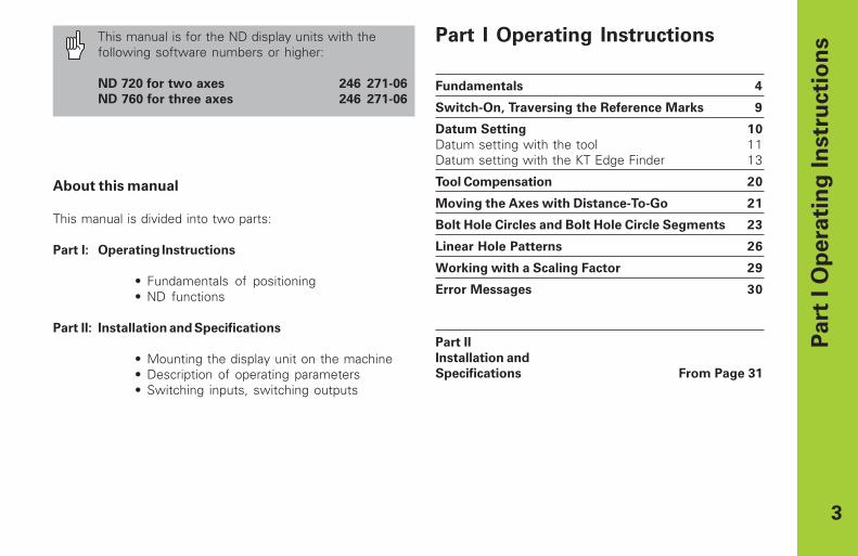
This manual is for the ND display units with thefollowing software numbers or higher:
ND 720 for two axes 246 271-06
ND 760 for three axes 246 271-06
About this manual
This manual is divided into two parts:
Part I: Operating Instructions
• Fundamentals of positioning• ND functions
Part II: Installation and Specifications
• Mounting the display unit on the machine• Description of operating parameters• Switching inputs, switching outputs
Part I Operating Instructions
Fundamentals 4
Switch-On, Traversing the Reference Marks 9
Datum Setting 10
Datum setting with the tool 11Datum setting with the KT Edge Finder 13
Tool Compensation 20
Moving the Axes with Distance-To-Go 21
Bolt Hole Circles and Bolt Hole Circle Segments 23
Linear Hole Patterns 26
Working with a Scaling Factor 29
Error Messages 30
Part II
Installation and
Specifications From Page 31
4
Y
X
Z
+Y
+X
+Z
–Z –Y
–X Datum ororigin
Graduation
Fu
nd
am
en
tals
Fundamentals
You can skip this chapter if you are already familiar withcoordinate systems, incremental and absolute dimensions,nominal positions, actual positions and distance-to-go.
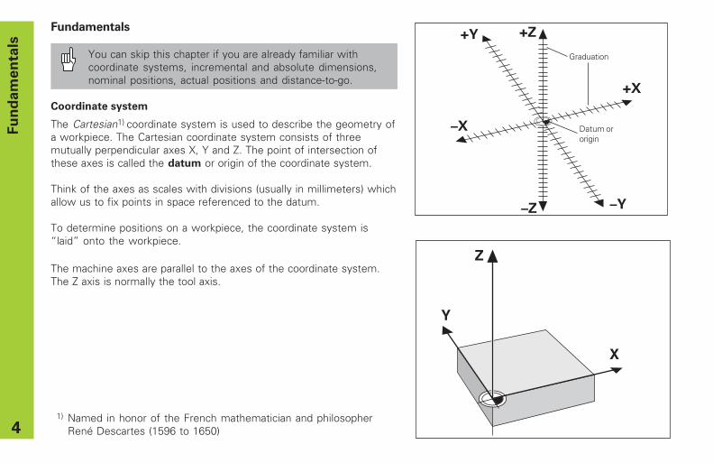
Coordinate system
The Cartesian1) coordinate system is used to describe the geometry ofa workpiece. The Cartesian coordinate system consists of threemutually perpendicular axes X, Y and Z. The point of intersection ofthese axes is called the datum or origin of the coordinate system.
Think of the axes as scales with divisions (usually in millimeters) whichallow us to fix points in space referenced to the datum.
To determine positions on a workpiece, the coordinate system is“laid” onto the workpiece.
The machine axes are parallel to the axes of the coordinate system.The Z axis is normally the tool axis.
1) Named in honor of the French mathematician and philosopherRené Descartes (1596 to 1650)
5
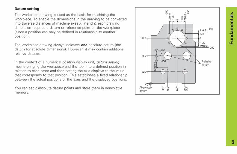
Datum setting
The workpiece drawing is used as the basis for machining theworkpiece. To enable the dimensions in the drawing to be convertedinto traverse distances of machine axes X, Y and Z, each drawingdimension requires a datum or reference point on the workpiece(since a position can only be defined in relationship to anotherposition).
The workpiece drawing always indicates one absolute datum (thedatum for absolute dimensions). However, it may contain additionalrelative datums.
In the context of a numerical position display unit, datum settingmeans bringing the workpiece and the tool into a defined position inrelation to each other and then setting the axis displays to the valuethat corresponds to that position. This establishes a fixed relationshipbetween the actual positions of the axes and the displayed positions.
You can set 2 absolute datum points and store them in nonvolatilememory.
Fu
nd
am
en
tals
0
325
450
700
900
950
0
320
750
1225
300±
0,1
0
150
-150
0
0
216,5 250
-250
-125-216,5
0-125
-216
,5-250 250
125
216,
5
125
Relativedatum
Absolutedatum
6
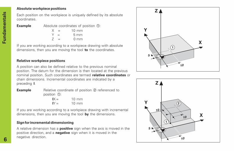
Absolute workpiece positions
Each position on the workpiece is uniquely defined by its absolutecoordinates.
Example Absolute coordinates of position 1:X = 10 mmY = 5 mmZ = 0 mm
If you are working according to a workpiece drawing with absolutedimensions, then you are moving the tool to the coordinates.
�
�
�
��
�
�
Fu
nd
am
en
tals
1
Y
X
Z
10
5
10
10
1
2
Relative workpiece positions
A position can also be defined relative to the previous nominalposition. The datum for the dimension is then located at the previousnominal position. Such coordinates are termed relative coordinates orchain dimensions. Incremental coordinates are indicated by apreceding I.
Example Relative coordinate of position 2 referenced toposition 1:
IX = 10 mmIY = 10 mm
If you are working according to a workpiece drawing with incrementaldimensions, then you are moving the tool by the dimensions.
Sign for incremental dimensioning
A relative dimension has a positive sign when the axis is moved in thepositive direction, and a negative sign when it is moved in thenegative direction.
7
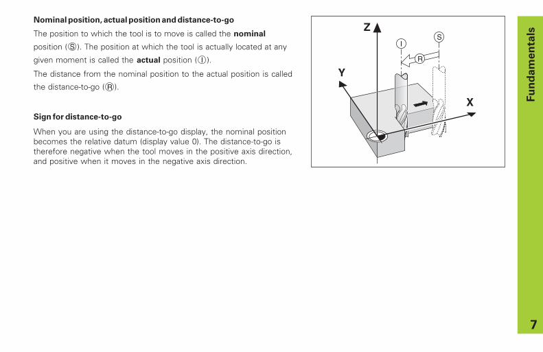
Nominal position, actual position and distance-to-go
The position to which the tool is to move is called the nominal
position ( S ). The position at which the tool is actually located at any
given moment is called the actual position ( I ).
The distance from the nominal position to the actual position is called
the distance-to-go ( R ).
Sign for distance-to-go
When you are using the distance-to-go display, the nominal positionbecomes the relative datum (display value 0). The distance-to-go istherefore negative when the tool moves in the positive axis direction,and positive when it moves in the negative axis direction.
Fu
nd
am
en
tals
Y
X
ZI
S
R
8
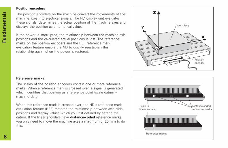
Position encoders
The position encoders on the machine convert the movements of themachine axes into electrical signals. The ND display unit evaluatesthese signals, determines the actual position of the machine axes anddisplays the position as a numerical value.
If the power is interrupted, the relationship between the machine axispositions and the calculated actual positions is lost. The referencemarks on the position encoders and the REF reference markevaluation feature enable the ND to quickly reestablish thisrelationship again when the power is restored.
Reference marks
The scales of the position encoders contain one or more referencemarks. When a reference mark is crossed over, a signal is generatedwhich identifies that position as a reference point (scale datum =machine datum).
When this reference mark is crossed over, the ND's reference markevaluation feature (REF) restores the relationship between axis slidepositions and display values which you last defined by setting thedatum. If the linear encoders have distance-coded reference marks,you only need to move the machine axes a maximum of 20 mm to dothis.
�
�
�
Workpiece
Position- encoder
Scale in Distance-coded linear encoder reference marks
Reference marks
Fu
nd
am
en
tals
9
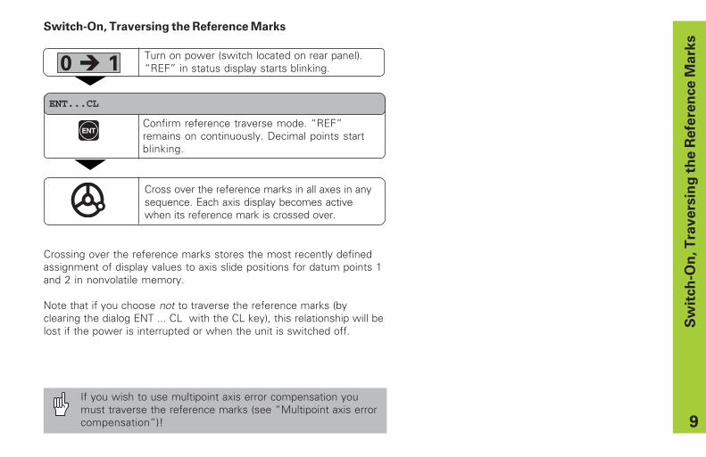
Switch-On, Traversing the Reference Marks
ENT...CL
Turn on power (switch located on rear panel).“REF” in status display starts blinking.
Confirm reference traverse mode. “REF”remains on continuously. Decimal points startblinking.
Cross over the reference marks in all axes in anysequence. Each axis display becomes activewhen its reference mark is crossed over.
0 � 1
ENT
Crossing over the reference marks stores the most recently definedassignment of display values to axis slide positions for datum points 1and 2 in nonvolatile memory.
Note that if you choose not to traverse the reference marks (byclearing the dialog ENT ... CL with the CL key), this relationship will belost if the power is interrupted or when the unit is switched off.
Sw
itch
-On
, T
ravers
ing
th
e R
efe
ren
ce M
ark
s
If you wish to use multipoint axis error compensation youmust traverse the reference marks (see “Multipoint axis errorcompensation”)!
10
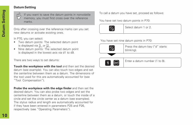
Datum Setting
If you want to save the datum points in nonvolatilememory, you must first cross over the referencemarks.
Press the datum key (“d” startsblinking).
Datu
m S
ett
ing
In P70, you can select:• Two datum points: The selected datum point
is displayed via 1 or 2• Nine datum points: The selected datum point
is displayed in the lowest axis via d1 to d9.
Touch the workpiece with the tool and then set the desireddatum (see example). You can also touch two edges and setthe centerline between them as a datum. The dimensions ofthe tool used for this are automatically accounted for (see“Tool Compensation”).
Probe the workpiece with the edge finder and then set thedesired datum. You can also probe two edges and set thecenterline between them as a datum, or touch the inside of acircle and set the circle center as a datum (see examples).The stylus radius and length are automatically accounted forif they have been entered in parameters P25 and P26,respectively (see “Operating Parameters”).
Enter a datum number (1 to 9).1 ENT
Only after crossing over the reference marks can you setnew datums or activate existing ones.
There are two ways to set datums:
To call a datum you have set, proceed as follows:
Select datum 1 or 2.
You have set two datum points in P70:
You have set nine datum points in P70:
11
Datu
m S
ett
ing
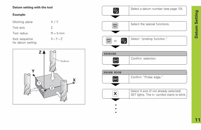
Select a datum number (see page 10).
Select the special functions.SPECFCT
PROBE EDGE
ENTConfirm “Probe edge.”
XSelect X axis (if not already selected).SET lights. The ❘<- symbol starts to blink.
Select “probing function.”
PROBING
ENTConfirm selection.
SPECFCT or
Y
X
21
Z
R=5mm
Datum setting with the tool
Example:
Working plane X / Y
Tool axis Z
Tool radius R = 5 mm
Axis sequence X – Y – Zfor datum setting
•••
12
Datu
m S
ett
ing
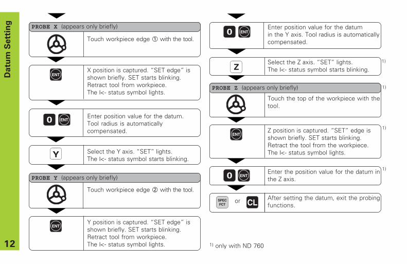
ZSelect the Z axis. “SET” lights.The ❘<- status symbol starts blinking.
Touch the top of the workpiece with thetool.
ENTZ position is captured. “SET” edge isshown briefly. SET starts blinking.Retract the tool from the workpiece.The ❘<- status symbol lights.
Enter the position value for the datum inthe Z axis.0 ENT
After setting the datum, exit the probingfunctions.
PROBE Z (appears only briefly)
SPECFCT
or CL
1)
1)
1)
1)
1) only with ND 760
•••
ENTY position is captured. “SET edge” isshown briefly. SET starts blinking.Retract tool from workpiece.The ❘<- status symbol lights.
Enter position value for the datumin the Y axis. Tool radius is automaticallycompensated.
0 ENT
•••
ENTX position is captured. “SET edge” isshown briefly. SET starts blinking.Retract tool from workpiece.The ❘<- status symbol lights.
Enter position value for the datum.Tool radius is automaticallycompensated.
0
Y Select the Y axis. “SET” lights.The ❘<- status symbol starts blinking.
ENT
Touch workpiece edge 2 with the tool.
PROBE Y (appears only briefly)
Touch workpiece edge 1 with the tool.
PROBE X (appears only briefly)
13
Datu
m S
ett
ing
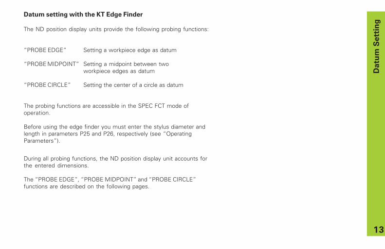
Datum setting with the KT Edge Finder
The ND position display units provide the following probing functions:
“PROBE EDGE” Setting a workpiece edge as datum
“PROBE MIDPOINT” Setting a midpoint between twoworkpiece edges as datum
“PROBE CIRCLE” Setting the center of a circle as datum
The probing functions are accessible in the SPEC FCT mode ofoperation. Before using the edge finder you must enter the stylus diameter andlength in parameters P25 and P26, respectively (see “OperatingParameters”).
During all probing functions, the ND position display unit accounts forthe entered dimensions.
The “PROBE EDGE”, “PROBE MIDPOINT” and “PROBE CIRCLE”functions are described on the following pages.
14
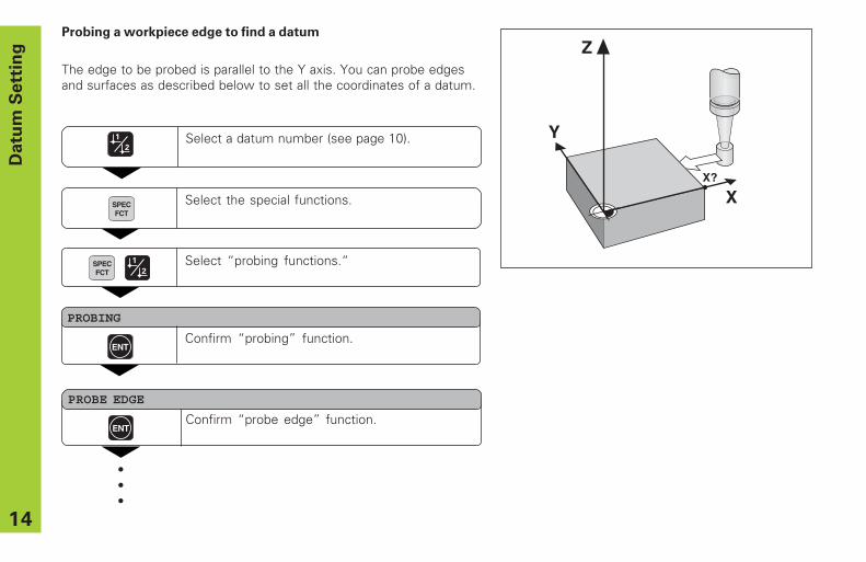
Probing a workpiece edge to find a datum
The edge to be probed is parallel to the Y axis. You can probe edgesand surfaces as described below to set all the coordinates of a datum.
Datu
m S
ett
ing
Y
X
Z
X?
Select a datum number (see page 10).
Select the special functions.SPECFCT
•••
Select “probing functions.“
PROBING
ENTConfirm “probing” function.
SPECFCT
ENTConfirm “probe edge” function.
PROBE EDGE
15
Datu
m S
ett
ing
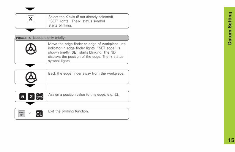
X Select the X axis (if not already selected).“SET” lights. The ❘< status symbolstarts blinking.
Move the edge finder to edge of workpiece untilindicator in edge finder lights. “SET edge” isshown briefly. SET starts blinking. The NDdisplays the position of the edge. The ❘< statussymbol lights.
Back the edge finder away from the workpiece.
5 2 Assign a position value to this edge, e.g. 52.
SPECFCT
Exit the probing function.
ENT
CL or
PROBE X (appears only briefly)
16
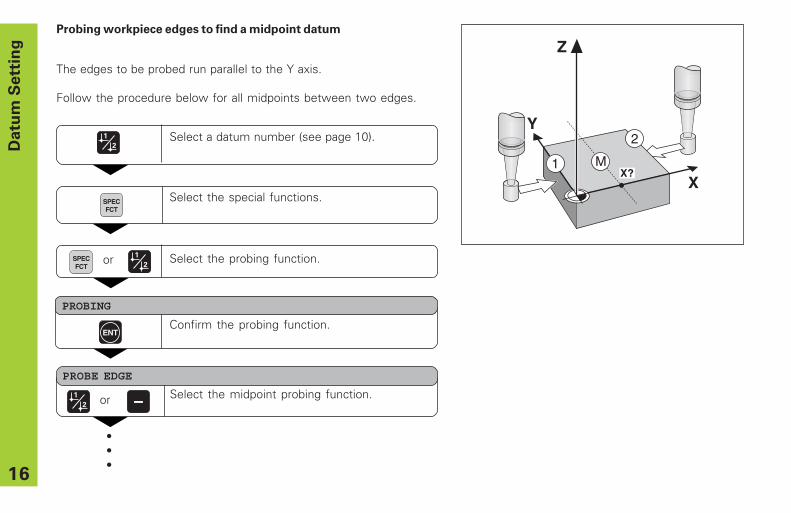
Probing workpiece edges to find a midpoint datum
The edges to be probed run parallel to the Y axis.
Follow the procedure below for all midpoints between two edges.
Y
X
2
1
Z
MX?
Datu
m S
ett
ing
Select the special functions.SPECFCT
•••
Select the probing function.
PROBING
ENTConfirm the probing function.
SPECFCT
or
Select a datum number (see page 10).
ANTASTEN MITTE Select the midpoint probing function.
PROBE EDGE
or
17
Datu
m S
ett
ing
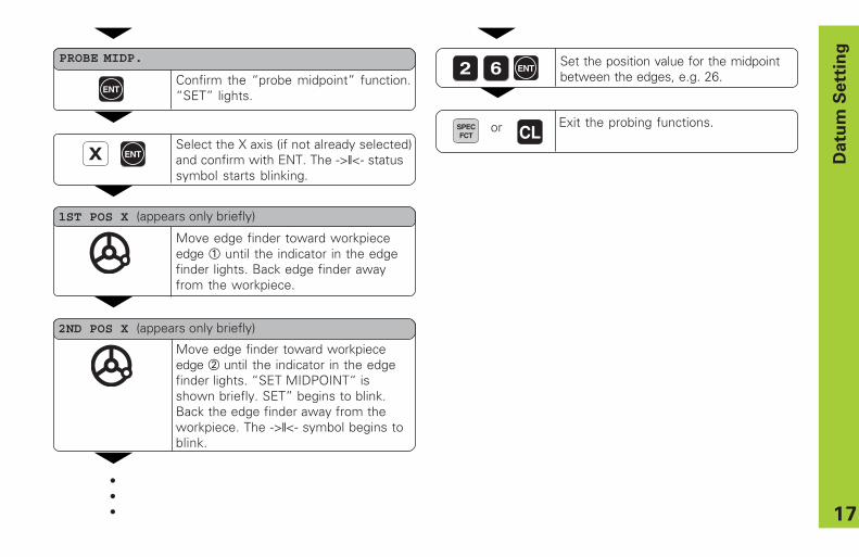
XSelect the X axis (if not already selected)and confirm with ENT. The ->❘❘<- statussymbol starts blinking.
Move edge finder toward workpieceedge 1 until the indicator in the edgefinder lights. Back edge finder awayfrom the workpiece.
Move edge finder toward workpieceedge 2 until the indicator in the edgefinder lights. “SET MIDPOINT“ isshown briefly. SET” begins to blink.Back the edge finder away from theworkpiece. The ->❘❘<- symbol begins toblink.
2 6 Set the position value for the midpointbetween the edges, e.g. 26.
Exit the probing functions.
ENT
ENT
SPECFCT CL or
1ST POS X (appears only briefly)
2ND POS X (appears only briefly)
•••
ENTConfirm the “probe midpoint” function.“SET” lights.
PROBE MIDP.
18
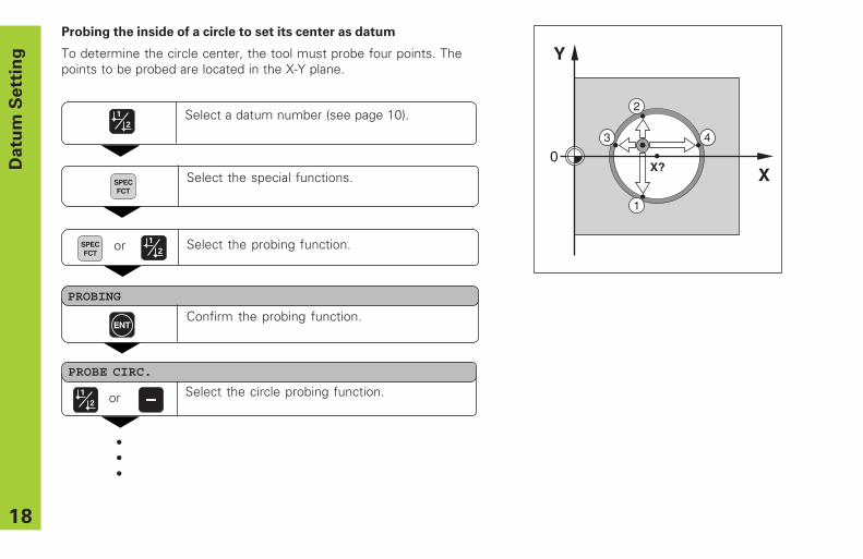
Probing the inside of a circle to set its center as datum
To determine the circle center, the tool must probe four points. Thepoints to be probed are located in the X-Y plane.
Da
tum
Se
ttin
g
Select the special functions.SPECFCT
•••
Select the probing function.
PROBING
ENTConfirm the probing function.
SPECFCT
or
Select a datum number (see page 10).
ANTASTEN MITTE Select the circle probing function.
PROBE CIRC.
or
Y
X0
1
2
3 4
X?
19
Datu
m S
ett
ing
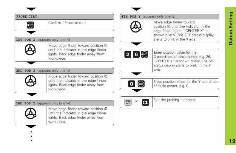
Move edge finder toward position 1until the indicator in the edge finderlights. Back edge finder away fromworkpiece.
Move edge finder toward position 2until the indicator in the edge finderlights. Back edge finder away fromworkpiece.
2 6 Enter position value for theX coordinate of circle center, e.g. 26.“CENTER Y” is shown briefly. The SETstatus display starts to blink in the Yaxis.
Exit the probing functions.
ENT
ENT
PROBE CIRC.
SPECFCT CL or
1ST POS X (appears only briefly)
2ND POS X (appears only briefly)
•••
Confirm “Probe circle.”
Move edge finder toward position 3until the indicator in the edge finderlights. Back edge finder away fromworkpiece.
3RD POS Y (appears only briefly)
Move edge finder towardposition 4 until the indicator in theedge finder lights. “CENTER X” isshown briefly. The SET status displaystarts to blink in the X axis.
4TH POS Y (appears only briefly)
Enter position value for the Y coordinateof circle center, e.g. 0.0 ENT
20
To
ol
Co
mp
en
sa
tio
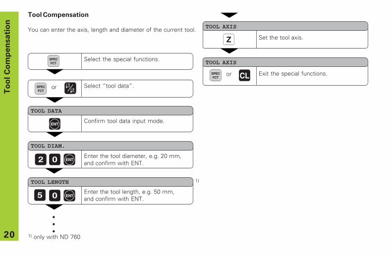
nTool Compensation
You can enter the axis, length and diameter of the current tool.
Select the special functions.
TOOL DIAM.
2 0 Enter the tool diameter, e.g. 20 mm,and confirm with ENT.
TOOL AXIS
Z Set the tool axis.
SPECFCT
ENT
TOOL DATA
ENTConfirm tool data input mode.
Select “tool data”.SPECFCT
TOOL LENGTH
0 ENT5
TOOL AXIS
Exit the special functions.
•••
SPECFCT
or CL or
1)
1) only with ND 760
Enter the tool length, e.g. 50 mm,and confirm with ENT.
21
Mo
vin
g t
he
Ax
es w
ith
Dis
tan
ce
-To
-Go
Dis
pla
y
Select the special functions.
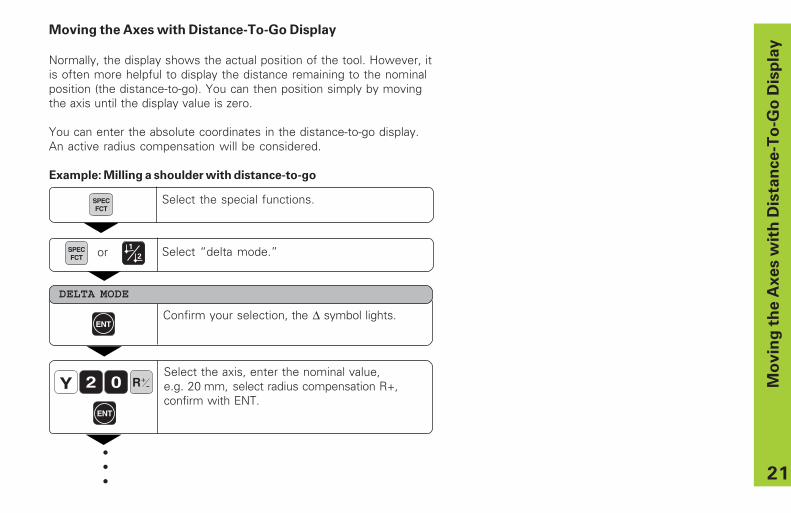
Moving the Axes with Distance-To-Go Display
Normally, the display shows the actual position of the tool. However, itis often more helpful to display the distance remaining to the nominalposition (the distance-to-go). You can then position simply by movingthe axis until the display value is zero.
You can enter the absolute coordinates in the distance-to-go display.An active radius compensation will be considered.
Example: Milling a shoulder with distance-to-go
R+-
Select the axis, enter the nominal value,e.g. 20 mm, select radius compensation R+,confirm with ENT.
ENT
Y 02
Confirm your selection, the ∆ symbol lights.ENT
DELTA MODE
SPECFCT
•••
Select “delta mode.”SPECFCT or
22
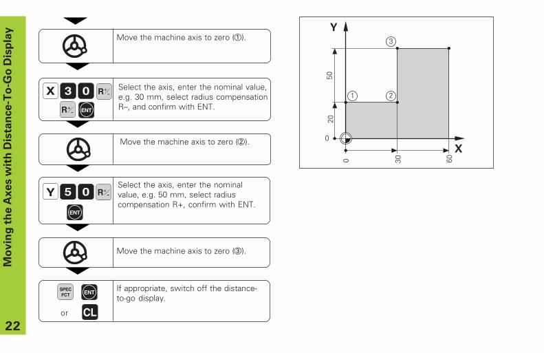
Y 0Select the axis, enter the nominalvalue, e.g. 50 mm, select radiuscompensation R+, confirm with ENT.
ENT
R+-
Mo
vin
g t
he
Ax
es w
ith
Dis
tan
ce
-To
-Go
Dis
pla
y
X 03 Select the axis, enter the nominal value,e.g. 30 mm, select radius compensationR–, and confirm with ENT.ENT
Move the machine axis to zero (2).
R+-
Move the machine axis to zero (1).
5
If appropriate, switch off the distance-to-go display.
SPECFCT ENT
CLor
R+-
Move the machine axis to zero (3).
23
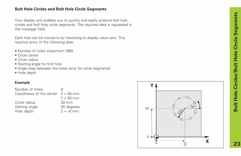
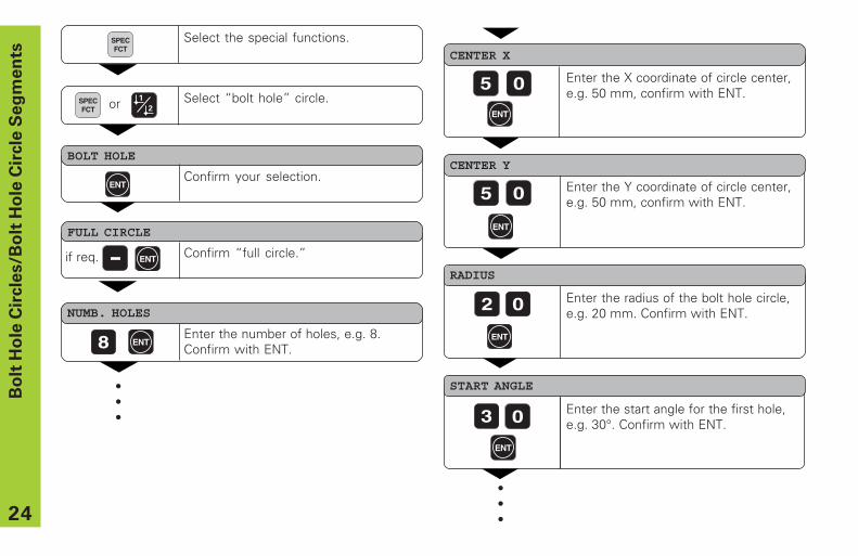
Bolt Hole Circles and Bolt Hole Circle Segments
Your display unit enables you to quickly and easily produce bolt holecircles and bolt hole circle segments. The required data is requested inthe message field.
Each hole can be moved to by traversing to display value zero. Thisrequires entry of the following data:
• Number of holes (maximum: 999)• Circle center• Circle radius• Starting angle for first hole• Angle step between the holes (only for circle segments)• Hole depth
Example
Number of holes 8Coordinates of the center X = 50 mm
Y = 50 mmCircle radius 20 mmStarting angle 30 degreesHole depth Z = –5 mm B
olt
Ho
le C
ircle
s/B
olt
Ho
le C
ircle
Se
gm
en
ts
Y
X
30°
R20
50
50
0
0
24
Bo
lt H
ole
Cir
cle
s/B
olt
Ho
le C
ircle
Se
gm
en
ts
Select the special functions.SPECFCT
NUMB. HOLES
8 Enter the number of holes, e.g. 8.Confirm with ENT.
•••
CENTER Y
5 0
CENTER X
5 0
02
RADIUS
START ANGLE
03
Enter the radius of the bolt hole circle,e.g. 20 mm. Confirm with ENT.
Enter the start angle for the first hole,e.g. 30°. Confirm with ENT.
•••
ENT
ENT
ENT
ENT
ENT
Select “bolt hole” circle.SPECFCT
BOLT HOLE
ENTConfirm your selection.
or
Enter the X coordinate of circle center,e.g. 50 mm, confirm with ENT.
Enter the Y coordinate of circle center,e.g. 50 mm, confirm with ENT.
FULL CIRCLE
ENT Confirm “full circle.”if req.
25
Bo
lt H
ole
Cir
cle
s/B
olt
Ho
le C
ircle
Se
gm
en
ts
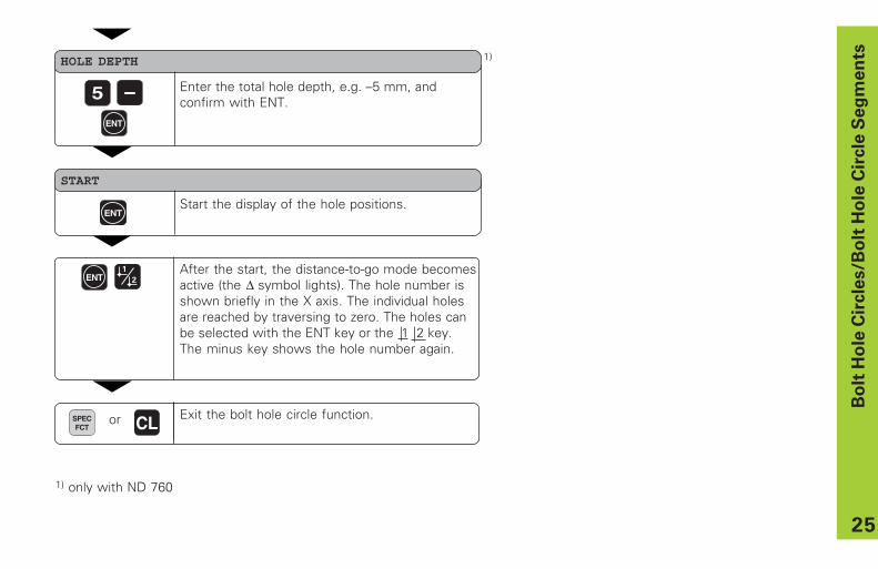
Enter the total hole depth, e.g. –5 mm, andconfirm with ENT.
HOLE DEPTH
5
START
ENTStart the display of the hole positions.
After the start, the distance-to-go mode becomesactive (the ∆ symbol lights). The hole number isshown briefly in the X axis. The individual holesare reached by traversing to zero. The holes canbe selected with the ENT key or the 1 2 key.The minus key shows the hole number again.
ENT
ENT
Exit the bolt hole circle function.SPECFCT
or CL
1)
1) only with ND 760
26
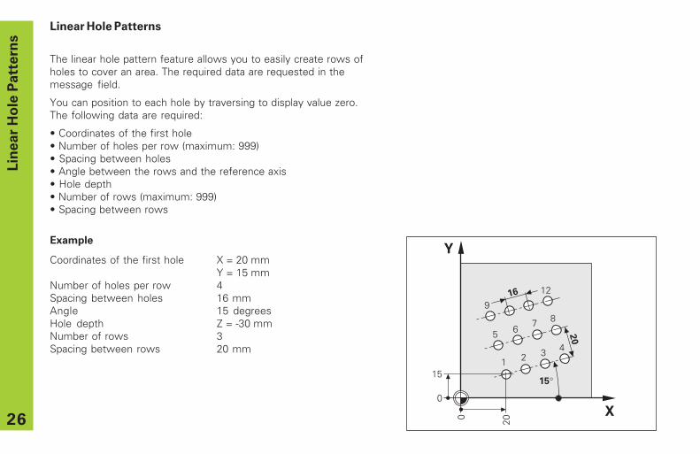
Linear Hole Patterns
The linear hole pattern feature allows you to easily create rows ofholes to cover an area. The required data are requested in themessage field.
You can position to each hole by traversing to display value zero.The following data are required:
• Coordinates of the first hole• Number of holes per row (maximum: 999)• Spacing between holes• Angle between the rows and the reference axis• Hole depth• Number of rows (maximum: 999)• Spacing between rows
Example
Coordinates of the first hole X = 20 mmY = 15 mm
Number of holes per row 4Spacing between holes 16 mmAngle 15 degreesHole depth Z = -30 mmNumber of rows 3Spacing between rows 20 mm
Lin
ear
Ho
le P
att
ern
s
Y
X
20
151
16
2 3 45 6
7 8
15°
20
9
12
0
0
27
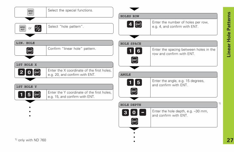
Select the special functions.SPECFCT
LIN. HOLE
ENTConfirm “linear hole” pattern.
1ST HOLE X
Enter the X coordinate of the first holes,e.g. 20, and confirm with ENT.
HOLES ROW
Enter the number of holes per row,e.g. 4, and confirm with ENT.
02
1ST HOLE Y
Enter the Y coordinate of the first holes,e.g. 15, and confirm with ENT.
•••
51
4
HOLE SPACE
Enter the spacing between holes in therow and confirm with ENT.
ANGLE
HOLE DEPTH
Enter the angle, e.g. 15 degrees,and confirm with ENT.
Enter the hole depth, e.g. –30 mm,and confirm with ENT.
•••
61
1 5
3 0
Lin
ear
Ho
le P
att
ern
s
ENT
ENT
ENT
ENT
ENT
ENT
Select “hole pattern”.SPECFCT
1)
1) only with ND 760
or
28
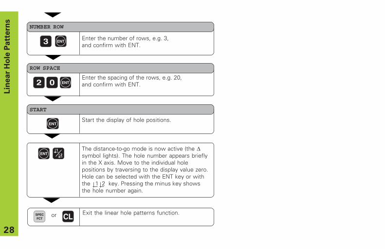
NUMBER ROW
3
ROW SPACE
Enter the spacing of the rows, e.g. 20,and confirm with ENT.
Enter the number of rows, e.g. 3,and confirm with ENT.
Lin
ear
Ho
le P
att
ern
s
02
START
ENTStart the display of hole positions.
The distance-to-go mode is now active (the ∆symbol lights). The hole number appears brieflyin the X axis. Move to the individual holepositions by traversing to the display value zero.Hole can be selected with the ENT key or withthe 1 2 key. Pressing the minus key showsthe hole number again.
ENT
ENT
ENT
Exit the linear hole patterns function.SPECFCT
or CL
29
Y
X
0
0
1
2
∗ 3.
0
∗ 3.5
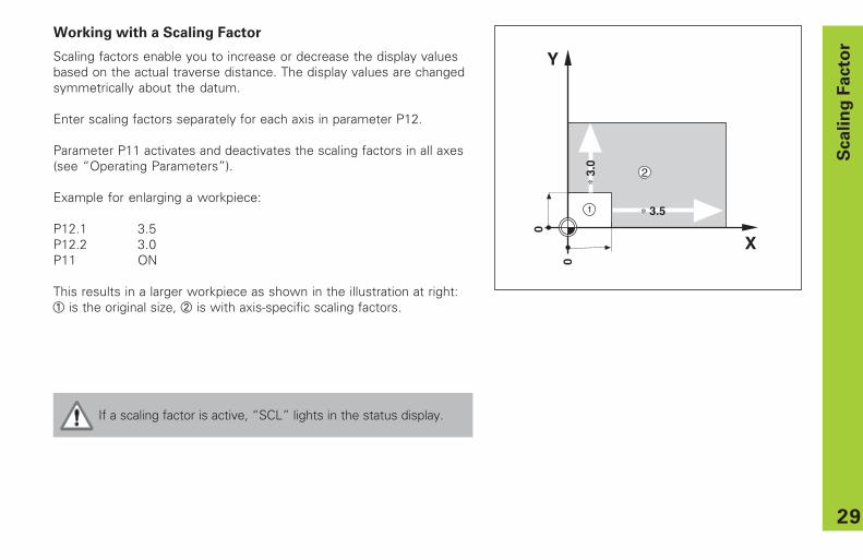
If a scaling factor is active, “SCL” lights in the status display.
Working with a Scaling Factor
Scaling factors enable you to increase or decrease the display valuesbased on the actual traverse distance. The display values are changedsymmetrically about the datum.
Enter scaling factors separately for each axis in parameter P12.
Parameter P11 activates and deactivates the scaling factors in all axes(see “Operating Parameters”).
Example for enlarging a workpiece:
P12.1 3.5P12.2 3.0P11 ON
This results in a larger workpiece as shown in the illustration at right:1 is the original size, 2 is with axis-specific scaling factors.
Scalin
g F
acto
r
30
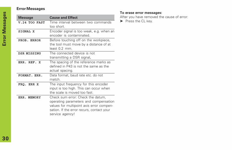
To erase error messages:
After you have removed the cause of error:➤ Press the CL key.
Error Messages
Message Cause and Effect
V.24 TOO FAST Time interval between two commandstoo short.
SIGNAL X Encoder signal is too weak, e.g. when anencoder is contaminated.
PROB. ERROR Before touching off on the workpiece,the tool must move by a distance of atleast 0.2 mm.
DSR MISSING The connected device is nottransmitting a DSR signal.....
ERR. REF. X The spacing of the reference marks asdefined in P43 is not the same as theactual spacing.
FORMAT. ERR. Data format, baud rate etc. do notmatch.
FRQ. ERR X The input frequency for this encoderinput is too high. This can occur whenthe scale is moved too fast.
ERR. MEMORY Check sum error: Check the datum,operating parameters and compensationvalues for multipoint axis error compen-sation. If the error recurs, contact yourservice agency!
Err
or
Messag
es
31
Part II Installation and Specifications
Items Supplied 32
Connections on Rear Panel 33
Mounting 34
Power connection 34
Connecting the Encoders 35
Operating Parameters 36Entering/changing operating parameters 36Operating parameter list 37
Linear Encoders 40Setting the display step 40Display step, signal period and subdivision 40Compatible HEIDENHAIN linear encoders 41
Multipoint Axis Error Compensation 43
Pin Layout of X10 46
Data Interface RS-232-C/V.24 47
Measured Value Output 48
Specifications 54Dimensions of ND 720/ND 760 55
Part
II
Insta
llati
on
an
d S
pecif
icati
on
s
32
Ite
ms S
up
pli
ed
Items Supplied
• ND 720 for 2 axesor
• ND 760 for 3 axes
• Power connector Id. Nr. 257 811-01
• User's Manual
Optional Accessories
• Tilting base for housing bottomId. Nr. 281 619-01
• KT 130 Edge Finder Id. Nr. 283 273-01
33
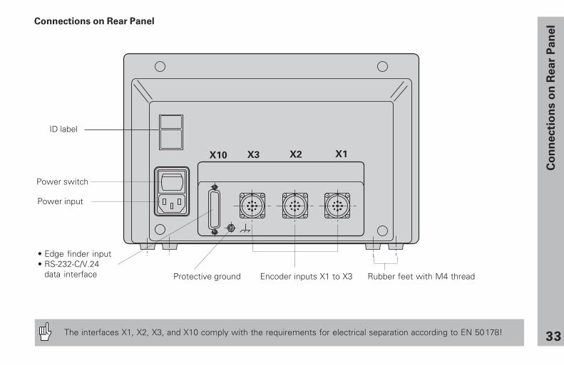
Power switch
ID label
Co
nn
ecti
on
s o
n R
ea
r P
an
el
Protective ground Encoder inputs X1 to X3 Rubber feet with M4 thread
Connections on Rear Panel
Power input
The interfaces X1, X2, X3, and X10 comply with the requirements for electrical separation according to EN 50178!
• Edge finder input• RS-232-C/V.24
data interface
34
Mo
un
tin
g/P
ow
er
Co
nn
ecti
on
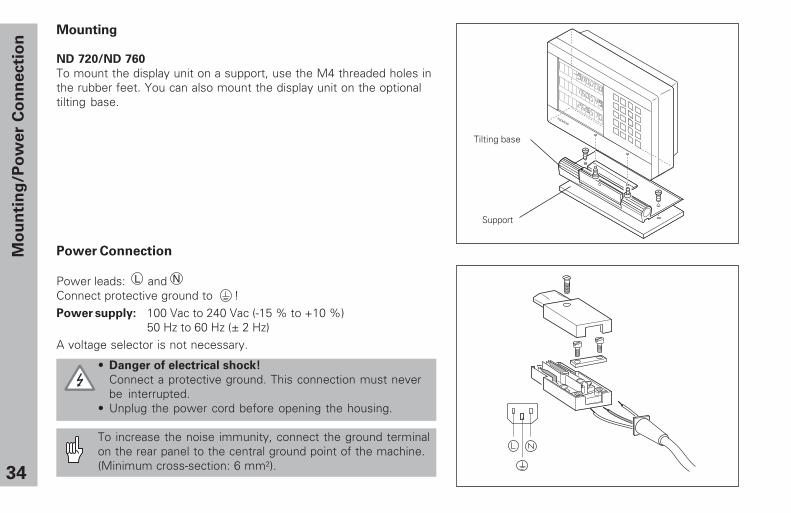
Mounting
ND 720/ND 760
To mount the display unit on a support, use the M4 threaded holes inthe rubber feet. You can also mount the display unit on the optionaltilting base.
Power Connection
Power leads: andConnect protective ground to !Power supply: 100 Vac to 240 Vac (-15 % to +10 %)
50 Hz to 60 Hz (± 2 Hz)A voltage selector is not necessary.
• Danger of electrical shock!
Connect a protective ground. This connection must neverbe interrupted.
• Unplug the power cord before opening the housing.
To increase the noise immunity, connect the ground terminalon the rear panel to the central ground point of the machine.(Minimum cross-section: 6 mm2).
L N
����������
Tilting base
Support
35
Co
nn
ecti
ng
th
e E
nco
de
rs
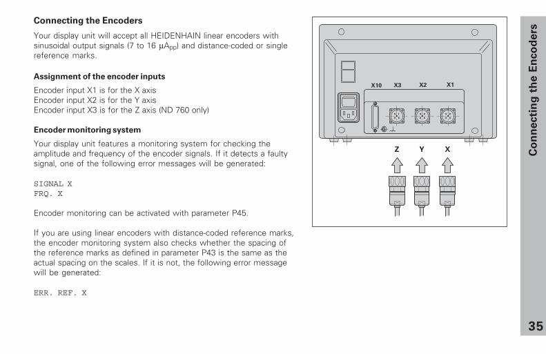
Connecting the Encoders
Your display unit will accept all HEIDENHAIN linear encoders withsinusoidal output signals (7 to 16 µApp) and distance-coded or singlereference marks.
Assignment of the encoder inputs
Encoder input X1 is for the X axisEncoder input X2 is for the Y axisEncoder input X3 is for the Z axis (ND 760 only)
Encoder monitoring system
Your display unit features a monitoring system for checking theamplitude and frequency of the encoder signals. If it detects a faultysignal, one of the following error messages will be generated:
SIGNAL XFRQ. X
Encoder monitoring can be activated with parameter P45.
If you are using linear encoders with distance-coded reference marks,the encoder monitoring system also checks whether the spacing ofthe reference marks as defined in parameter P43 is the same as theactual spacing on the scales. If it is not, the following error messagewill be generated:
ERR. REF. X
� � �
36
Op
era
tin
g P
ara
mete
rsOperating Parameters
Operating parameters allow you to modify the operatingcharacteristics of your display unit and define the evaluationof the encoder signals. Operating parameters that can bechanged by the user are called user parameters, and can beaccessed with the SPEC FCT key and the dialog “PARA-METER” (user parameters are identified as such in theparameter list). The full range of parameters can only beaccessed through the dialog “CODE“ and by entering 95148.
Operating parameters are designated by the letter P and anumber. Example: P11. . . . . The parameter designation is shownin the input field when you select it with the DATUM andENT key in the X display. The parameter setting is shown inthe Y display.
Some operating parameters have separate values for eachaxis. In the ND 760, these parameters are identified by anindex of 1 to 3, and in the ND 720 by an index of one to two.Example: P12.1 scaling factor, X axis
P12.2 scaling factor, Y axisP12.3 scaling factor, Z axis (ND 760 only)
The operating parameters are preset before the unit leavesthe factory. These factory default settings are indicated in theparameter list in boldface type.
Entering and changing operating parameters
To access the operating parameters
➤ Press the SPEC FCT key.➤ Press the SPEC FCT key or 1 2 , until
“PARAMETER” appears in the X display.➤ Confirm your selection by pressing ENT.
To select protected operating parameters
➤ Press the 1 2 key to select theP00 CODE user parameter.
➤ Enter the code number 95148.➤ Confirm with the ENT key.
To page through the operating parameters
➤ Page forwards by pressing the ENT key.➤ Page backwards by pressing the 1 2 key.
To change parameter settings
➤ Press the minus key or enter the value and confirmwith the ENT key.
To correct an entry
➤ Press CL: the old value reappears in the input line andbecomes effective again.
To exit the operating parameters
➤ Press the SPEC FCT or CL key.
37
Op
era
tin
g P
ara
mete
rs
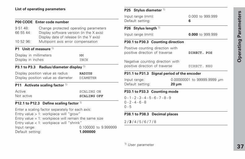
List of operating parameters
P00 CODE Enter code number
9 51 48: Change protected operating parameters66 55 44: Display software version (in the X axis)
Display date of release (in the Y axis)10 52 96: Multipoint axis error compensation
P1 Unit of measure 1)
Display in millimeters MMDisplay in inches INCH
P3.1 to P3.3 Radius/diameter display 1)
Display position value as radius RADIUSDisplay position value as diameter DIAMETER
P11 Activate scaling factor 1)
Active SCALING ONNot active SCALING OFF
P12.1 to P12.3 Define scaling factor 1)
Enter a scaling factor separately for each axis:Entry value > 1: workpiece will “grow”Entry value = 1: workpiece will remain the same sizeEntry value < 1: workpiece will “shrink”Input range: 0.100000 to 9.999999Default setting: 1.000000
P25 Stylus diameter 1)
Input range (mm): 0.000 to 999.999Default setting: 6
P26 Stylus length 1)
Input range (mm): 0.000 to 999.999
P30.1 to P30.3 Counting direction
Positive counting direction withpositive direction of traverse DIRECT. POS
Negative counting direction withpositive direction of traverse DIRECT. NEG
P31.1 to P31.3 Signal period of the encoder
Input range: 0.00000001 to 99999.9999 µmDefault setting: 20 µm
P33.1 to P33.3 Counting mode
0 - 1 - 2 - 3 - 4 - 5 - 6 - 7 - 8 - 90 - 2 - 4 - 6 - 80 - 5
P38.1 to P38.3 Decimal places
2 / 3 / 4 / 5 / 6 / 7 / 8
1) User parameter
38
Op
era
tin
g P
ara
mete
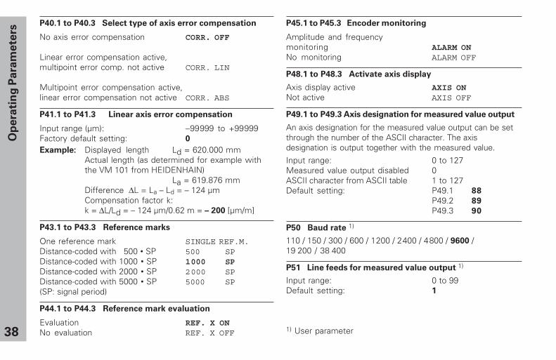
rsP40.1 to P40.3 Select type of axis error compensation
No axis error compensation CORR. OFF
Linear error compensation active,multipoint error comp. not active CORR. LIN
Multipoint error compensation active,linear error compensation not active CORR. ABS
P41.1 to P41.3 Linear axis error compensation
Input range (µm): −99999 to +99999Factory default setting: 0
Example: Displayed length Ld = 620.000 mmActual length (as determined for example withthe VM 101 from HEIDENHAIN)
La = 619.876 mmDifference ∆L = La – Ld = – 124 µmCompensation factor k:k = ∆L/Ld = – 124 µm/0.62 m = – 200 [µm/m]
P43.1 to P43.3 Reference marks
One reference mark SINGLE REF.M.Distance-coded with 500 • SP 500 SPDistance-coded with 1000 • SP 1000 SPDistance-coded with 2000 • SP 2000 SPDistance-coded with 5000 • SP 5000 SP(SP: signal period)
P44.1 to P44.3 Reference mark evaluation
Evaluation REF. X ONNo evaluation REF. X OFF
P45.1 to P45.3 Encoder monitoring
Amplitude and frequencymonitoring ALARM ONNo monitoring ALARM OFF
P48.1 to P48.3 Activate axis display
Axis display active AXIS ONNot active AXIS OFF
P49.1 to P49.3 Axis designation for measured value output
An axis designation for the measured value output can be setthrough the number of the ASCII character. The axisdesignation is output together with the measured value.
Input range: 0 to 127Measured value output disabled 0ASCII character from ASCII table 1 to 127Default setting: P49.1 88
P49.2 89
P49.3 90
P50 Baud rate 1)
110 / 150 / 300 / 600 / 1200 / 2 400 / 4 800 / 9600 /19 200 / 38 400
P51 Line feeds for measured value output 1)
Input range: 0 to 99Default setting: 1
1) User parameter
39
Op
era
tin
g P
ara
mete
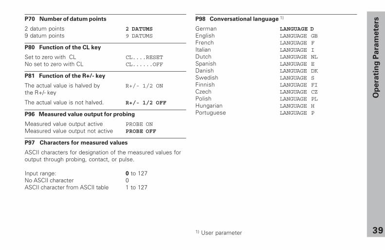
rsP70 Number of datum points
2 datum points 2 DATUMS9 datum points 9 DATUMS
P80 Function of the CL key
Set to zero with CL CL....RESETNo set to zero with CL CL......OFF
P81 Function of the R+/- key
The actual value is halved by R+/- 1/2 ONthe R+/- key
The actual value is not halved. R+/- 1/2 OFF
P96 Measured value output for probing
Measured value output active PROBE ONMeasured value output not active PROBE OFF
P97 Characters for measured values
ASCII characters for designation of the measured values foroutput through probing, contact, or pulse.
Input range: 0 to 127No ASCII character 0ASCII character from ASCII table 1 to 127
1) User parameter
P98 Conversational language 1)
German LANGUAGE DEnglish LANGUAGE GBFrench LANGUAGE FItalian LANGUAGE IDutch LANGUAGE NLSpanish LANGUAGE EDanish LANGUAGE DKSwedish LANGUAGE SFinnish LANGUAGE FICzech LANGUAGE CZPolish LANGUAGE PLHungarian LANGUAGE HPortuguese LANGUAGE P
40
Lin
ear
En
co
ders
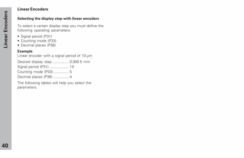
Linear Encoders
Selecting the display step with linear encoders
To select a certain display step you must define thefollowing operating parameters:
• Signal period (P31)• Counting mode (P33)• Decimal places (P38)
Example
Linear encoder with a signal period of 10 µm
Desired display step ................ 0.000 5 mmSignal period (P31) ................... 10Counting mode (P33) ............... 5Decimal places (P38) ............... 4
The following tables will help you select theparameters.
41
Lin
ear
en
co
ders
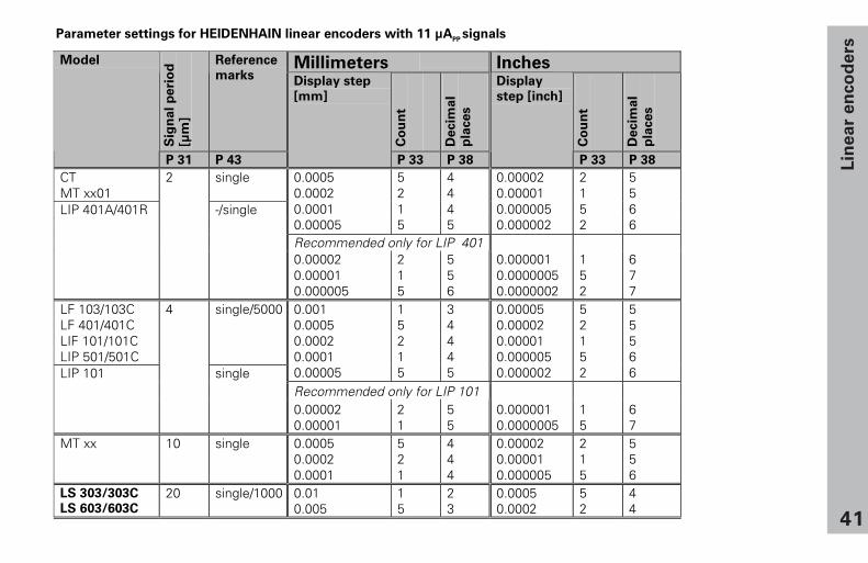
Parameter settings for HEIDENHAIN linear encoders with 11 µAPP
signals
Millimeters Inches
Sig
nal
pe
rio
d[µ
m]
Reference
marks
Co
un
t
De
cim
al
pla
ces
Co
un
t
De
cim
al
pla
ces
Model
P 31 P 43
Display step
[mm]
P 33 P 38
Display
step [inch]
P 33 P 38
CTMT xx01
single 0.00050.00020.00010.00005
5215
4445
0.000020.000010.0000050.000002
2152
5566
Recommended only for LIP 401
LIP 401A/401R
2
-/single
0.000020.000010.000005
215
556
0.0000010.00000050.0000002
152
677
LF 103/103CLF 401/401CLIF 101/101CLIP 501/501C
single/5000 0.0010.00050.00020.00010.00005
15215
34445
0.000050.000020.000010.0000050.000002
52152
55566
Recommended only for LIP 101LIP 101
4
single
0.000020.00001
21
55
0.0000010.0000005
15
67
MT xx 10 single 0.00050.00020.0001
521
444
0.000020.000010.000005
215
556
LS 303/303C
LS 603/603C20 single/1000 0.01
0.00515
23
0.00050.0002
52
44
42
Lin
ear
En
co
ders
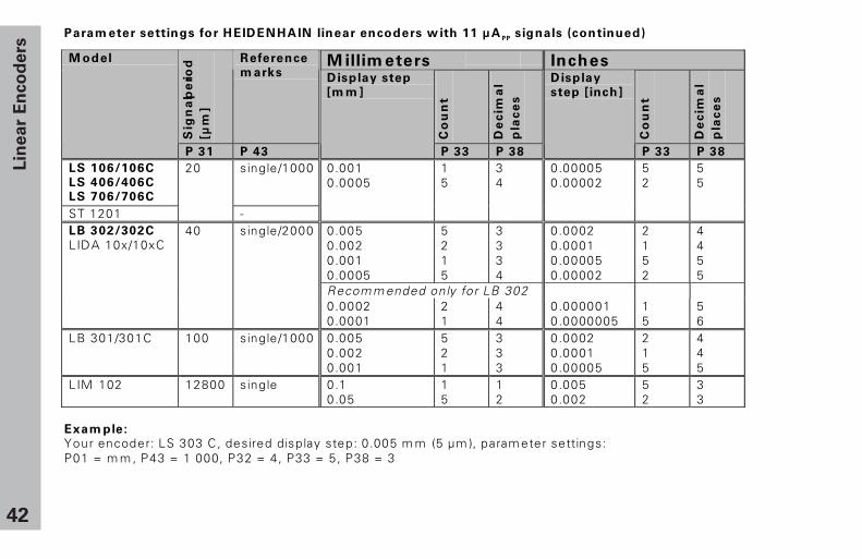
Param eter settings for HEIDENHAIN linear encoders w ith 11 µAPP
signals (continued)
M illim eters Inches
Sig
na
l pe
riod
[µm
]
Reference
m arks
Co
un
t
De
cim
al
pla
ce
s
Co
un
t
De
cim
al
pla
ce
s
M odel
P 31 P 43
Display step
[m m ]
P 33 P 38
Display
step [inch]
P 33 P 38
LS 106/106C
LS 406/406C
LS 706/706C
single/1000
ST 1201
20
-
0.0010.0005
15
34
0.000050.00002
52
55
0.0050.0020.0010.0005
5215
3334
0.00020.00010.000050.00002
2152
4455
Recom m ended only for LB 302
LB 302/302C
LIDA 10x/10xC40 single/2000
0.00020.0001
21
44
0.0000010.0000005
15
56
LB 301/301C 100 single/1000 0.0050.0020.001
521
333
0.00020.00010.00005
215
445
LIM 102 12800 single 0.10.05
15
12
0.0050.002
52
33
Exam ple:
Your encoder: LS 303 C, desired display step: 0.005 m m (5 µm ), param eter settings:P01 = m m , P43 = 1 000, P32 = 4, P33 = 5, P38 = 3
43
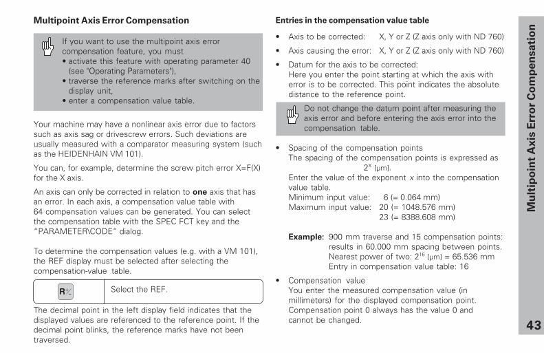
Multipoint Axis Error Compensation
If you want to use the multipoint axis errorcompensation feature, you must• activate this feature with operating parameter 40
(see "Operating Parameters"),• traverse the reference marks after switching on the
display unit,• enter a compensation value table.
Entries in the compensation value table
• Axis to be corrected: X, Y or Z (Z axis only with ND 760)
• Axis causing the error: X, Y or Z (Z axis only with ND 760)
• Datum for the axis to be corrected:Here you enter the point starting at which the axis witherror is to be corrected. This point indicates the absolutedistance to the reference point.
Do not change the datum point after measuring theaxis error and before entering the axis error into thecompensation table.
• Spacing of the compensation pointsThe spacing of the compensation points is expressed as
2x [µm].Enter the value of the exponent x into the compensationvalue table.Minimum input value: 6 (= 0.064 mm)Maximum input value: 20 (= 1048.576 mm)
23 (= 8388.608 mm)
Example: 900 mm traverse and 15 compensation points:results in 60.000 mm spacing between points.Nearest power of two: 216 [µm] = 65.536 mmEntry in compensation value table: 16
• Compensation valueYou enter the measured compensation value (inmillimeters) for the displayed compensation point.Compensation point 0 always has the value 0 andcannot be changed.
Mu
ltip
oin
t A
xis
Err
or
Co
mp
en
sa
tio
n
Your machine may have a nonlinear axis error due to factorssuch as axis sag or drivescrew errors. Such deviations areusually measured with a comparator measuring system (suchas the HEIDENHAIN VM 101).
You can, for example, determine the screw pitch error X=F(X)for the X axis.
An axis can only be corrected in relation to one axis that hasan error. In each axis, a compensation value table with64 compensation values can be generated. You can selectthe compensation table with the SPEC FCT key and the“PARAMETER\CODE” dialog.
To determine the compensation values (e.g. with a VM 101),the REF display must be selected after selecting thecompensation-value table.
Select the REF.R+-
The decimal point in the left display field indicates that thedisplayed values are referenced to the reference point. If thedecimal point blinks, the reference marks have not beentraversed.
44
Mu
ltip
oin
t A
xis
Err
or
Co
mp
en
sa
tio
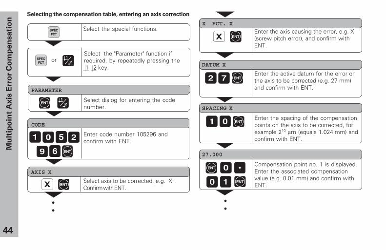
nSelecting the compensation table, entering an axis correction
DATUM X
Enter the active datum for the error onthe axis to be corrected (e.g. 27 mm)and confirm with ENT.
SPACING X
Enter the spacing of the compensationpoints on the axis to be corrected, forexample 210 µm (equals 1.024 mm) andconfirm with ENT.
27.000
Compensation point no. 1 is displayed.Enter the associated compensationvalue (e.g. 0.01 mm) and confirm withENT.
Select the special functions.
PARAMETER
Select dialog for entering the codenumber.
CODE
Enter code number 105296 andconfirm with ENT.
AXIS X
Select axis to be corrected, e.g. X.Confirm with ENT.
X FCT. X
Enter the axis causing the error, e.g. X(screw pitch error), and confirm withENT.
••
SPECFCT
ENT
ENT
ENT
ENT
ENT
ENT
Select the "Parameter" function ifrequired, by repeatedly pressing the 1 2 key.
SPECFCT
or
••
45
Mu
ltip
oin
t A
xis
Err
or
Co
mp
en
sa
tio
n
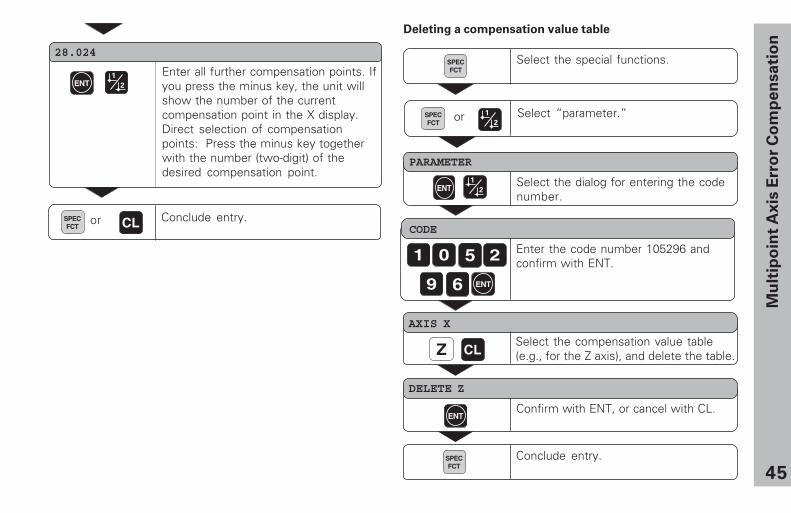
AXIS X
Select the compensation value table(e.g., for the Z axis), and delete the table.
DELETE Z
Confirm with ENT, or cancel with CL.
Conclude entry.
Deleting a compensation value table
Select the special functions.
PARAMETER
Select the dialog for entering the codenumber.
CODE
Enter the code number 105296 andconfirm with ENT.
SPECFCT
Select “parameter.”SPECFCT
or
28.024
Enter all further compensation points. Ifyou press the minus key, the unit willshow the number of the currentcompensation point in the X display.Direct selection of compensationpoints: Press the minus key togetherwith the number (two-digit) of thedesired compensation point.
Conclude entry.or
46
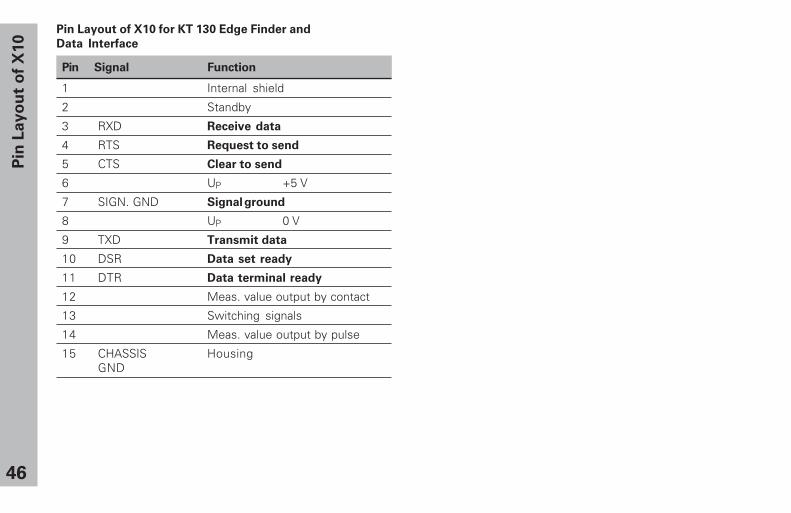
Pin Layout of X10 for KT 130 Edge Finder and
Data Interface
Pin Signal Function
1 Internal shield
2 Standby
3 RXD Receive data
4 RTS Request to send
5 CTS Clear to send
6 UP +5 V
7 SIGN. GND Signal ground
8 UP 0 V
9 TXD Transmit data
10 DSR Data set ready
11 DTR Data terminal ready
12 Meas. value output by contact
13 Switching signals
14 Meas. value output by pulse
15 CHASSIS HousingGND
Pin
La
yo
ut
of
X1
0
47
�����
�
���
�
��
���
�� �����
�� ���������
��
������� ���
���
�� �����
�� ���������
��
�������
Simplified wiring
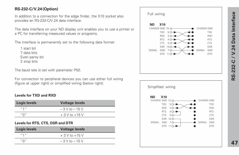
Full wiringRS-232-C/V.24 (Option)
In addition to a connection for the edge finder, the X10 socket alsoprovides an RS-232-C/V.24 data interface.
The data interface on your ND display unit enables you to use a printer ora PC for transferring measured values or programs.
The interface is permanently set to the following data format:
1 start bit7 data bitsEven parity bit2 stop bits
The baud rate is set with parameter P50.
For connection to peripheral devices you can use either full wiring(figure at upper right) or simplified wiring (below right).
RS
-232-C
/ V
.24 D
ata
In
terf
ace
�����
�
���
�
��
���
�� �����
�� ���������
��
������� ���
���
�� �����
�� ���������
��
�������
Levels for TXD and RXD
Logic levels Voltage levels
“1” – 3 V to – 15 V
“0” + 3 V to +15 V
Levels for RTS, CTS, DSR and DTR
Logic levels Voltage levels
“1” + 3 V to +15 V
“0” – 3 V to – 15 V
ND X10
ND X10
48
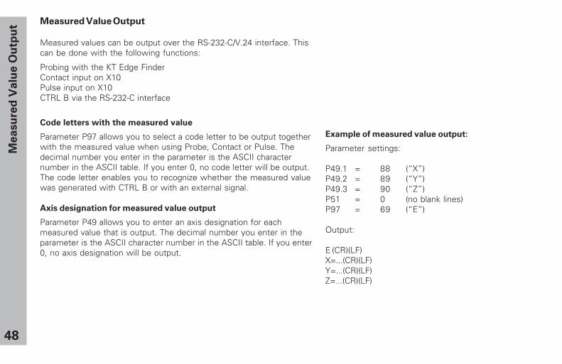
Measured Value Output
Measured values can be output over the RS-232-C/V.24 interface. Thiscan be done with the following functions:
Probing with the KT Edge FinderContact input on X10Pulse input on X10CTRL B via the RS-232-C interface
Code letters with the measured value
Parameter P97 allows you to select a code letter to be output togetherwith the measured value when using Probe, Contact or Pulse. Thedecimal number you enter in the parameter is the ASCII characternumber in the ASCII table. If you enter 0, no code letter will be output.The code letter enables you to recognize whether the measured valuewas generated with CTRL B or with an external signal.
Axis designation for measured value output
Parameter P49 allows you to enter an axis designation for eachmeasured value that is output. The decimal number you enter in theparameter is the ASCII character number in the ASCII table. If you enter0, no axis designation will be output.
Example of measured value output:
Parameter settings:
P49.1 = 88 (“X”)P49.2 = 89 (“Y”)P49.3 = 90 (“Z”)P51 = 0 (no blank lines)P97 = 69 (“E”)
Output:
E (CR)(LF)X=...(CR)(LF)Y=...(CR)(LF)Z=...(CR)(LF)
Me
asu
red
Va
lue
Ou
tpu
t
49
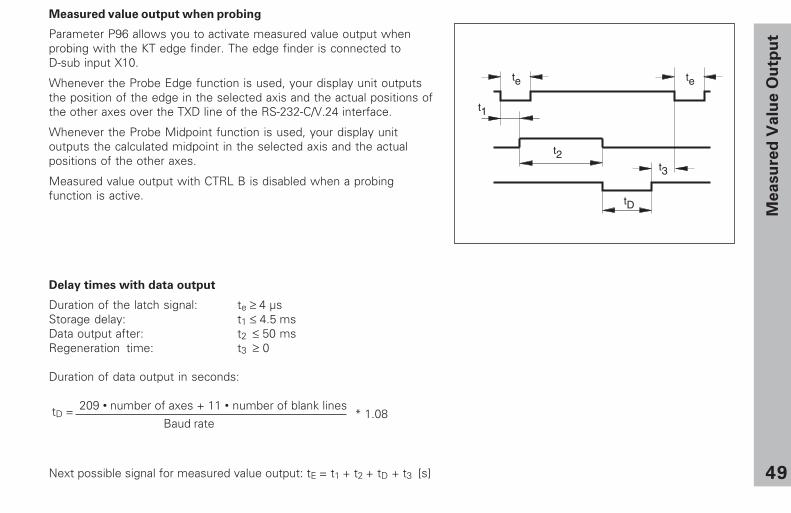
Delay times with data output
Duration of the latch signal: te ≥ 4 µsStorage delay: t1 ≤ 4.5 msData output after: t2 ≤ 50 msRegeneration time: t3 ≥ 0
Duration of data output in seconds:
209 • number of axes + 11 • number of blank lines
tD =
Baud rate
Measured value output when probing
Parameter P96 allows you to activate measured value output whenprobing with the KT edge finder. The edge finder is connected toD-sub input X10.
Whenever the Probe Edge function is used, your display unit outputsthe position of the edge in the selected axis and the actual positions ofthe other axes over the TXD line of the RS-232-C/V.24 interface.
Whenever the Probe Midpoint function is used, your display unitoutputs the calculated midpoint in the selected axis and the actualpositions of the other axes.
Measured value output with CTRL B is disabled when a probingfunction is active.
Next possible signal for measured value output: tE = t1 + t2 + tD + t3 [s]
t2
t1
t3
tD
te te
Me
asu
red
Va
lue
Ou
tpu
t
* 1.08
50
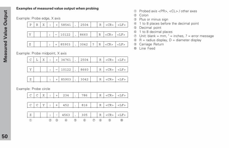
Examples of measured value output when probing
Example: Probe edge, X axis
P R X : + 58541 . 2504 R <CR> <LF>
Y : − 10122 . 8660 R <CR> <LF>
Z : + 85903 . 3042 ? R <CR> <LF>
Example: Probe midpoint, X axis
C L X : + 34761 . 2504 R <CR> <LF>
Y : − 10122 . 8660 R <CR> <LF>
Z : + 85903 . 3042 R <CR> <LF>
Example: Probe circle
C C X : + 234 . 786 R <CR> <LF>
C C Y : + 452 . 816 R <CR> <LF>
Z : - 4563 . 305 R <CR> <LF>
➀ ➁ ➂ ➃ ➄ ➅ ➆ ➇ ➈ ➉
Me
asu
red
Va
lue
Ou
tpu
t ➀ Probed axis <PR>, <CL> / other axes➁ Colon➂ Plus or minus sign➃ 1 to 8 places before the decimal point➄ Decimal point➅ 1 to 8 decimal places➆ Unit: blank = mm, " = inches, ? = error message➇ R = radius display, D = diameter display➈ Carriage Return➉ Line Feed
51
t2
t1
t3
tD
te te
Next possible signal for measured value output: tE = t1 + t2 + tD + t3 [s]
����������
������
������
����������
���
���
Me
asu
red
Va
lue
Ou
tpu
t
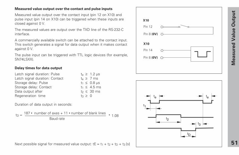
Measured value output over the contact and pulse inputs
Measured value output over the contact input (pin 12 on X10) andpulse input (pin 14 on X10) can be triggered when these inputs areclosed against 0 V.
The measured values are output over the TXD line of the RS-232-Cinterface.
A commercially available switch can be attached to the contact input.This switch generates a signal for data output when it makes contactagainst 0 V.
The pulse input can be triggered with TTL logic devices (for example,SN74LSXX).
Delay times for data output
Latch signal duration: Pulse te ≥ 1.2 µsLatch signal duration: Contact te ≥ 7 msStorage delay: Pulse t1 ≤ 0.8 µsStorage delay: Contact t1 ≤ 4.5 msData output after t2 ≤ 30 msRegeneration time t3 ≥ 0
Duration of data output in seconds:
187 • number of axes + 11 • number of blank lines
tD =
Baud rate* 1.08
52
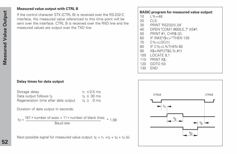
Delay times for data output
Storage delay t1 ≤ 0.5 msData output follows t2 t2 ≤ 30 msRegeneration time after data output t3 ≥ 0 ms
Duration of data output in seconds:
187 • number of axes + 11 • number of blank lines
tD =
Baud ratet2
t3
tD
CTRLB CTRLB
t1
Measured value output with CTRL B
If the control character STX (CTRL B) is received over the RS-232-Cinterface, the measured value referenced to this time point will besent over the interface. CTRL B is received over the RXD line and themeasured values are output over the TXD line.
Next possible signal for measured value output: tE = t1 +t2 + tD + t3 [s]
Me
asu
red
Va
lue
Ou
tpu
t BASIC program for measured value output:
10 L%=48 20 CLS 30 PRINT "RS232/V.24" 40 OPEN "COM1:9600,E,7" AS#1 50 PRINT #1, CHR$ (2); 60 IF INKEY$<>""THEN 130 70 C%=LOC(1) 80 IF C%<L%THEN 60 90 X$=INPUT$(L%,#1) 100 LOCATE 9,1 110 PRINT X$; 120 GOTO 50 130 END
* 1.08
53
Me
asu
red
Va
lue
Ou
tpu
t
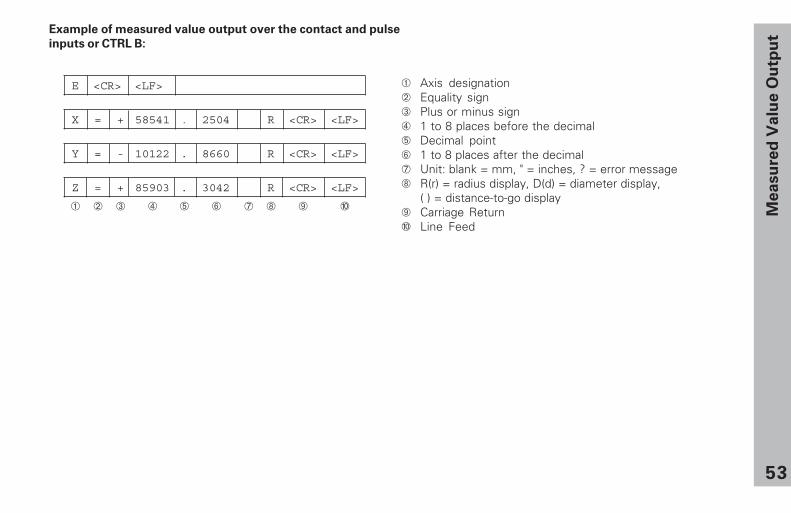
Example of measured value output over the contact and pulse
inputs or CTRL B:
E <CR> <LF>
X = + 58541 . 2504 R <CR> <LF>
Y = - 10122 . 8660 R <CR> <LF>
Z = + 85903 . 3042 R <CR> <LF>
➀ ➁ ➂ ➃ ➄ ➅ ➆ ➇ ➈ ➉
➀ Axis designation➁ Equality sign➂ Plus or minus sign➃ 1 to 8 places before the decimal➄ Decimal point➅ 1 to 8 places after the decimal➆ Unit: blank = mm, " = inches, ? = error message➇ R(r) = radius display, D(d) = diameter display,
( ) = distance-to-go display➈ Carriage Return➉ Line Feed
54
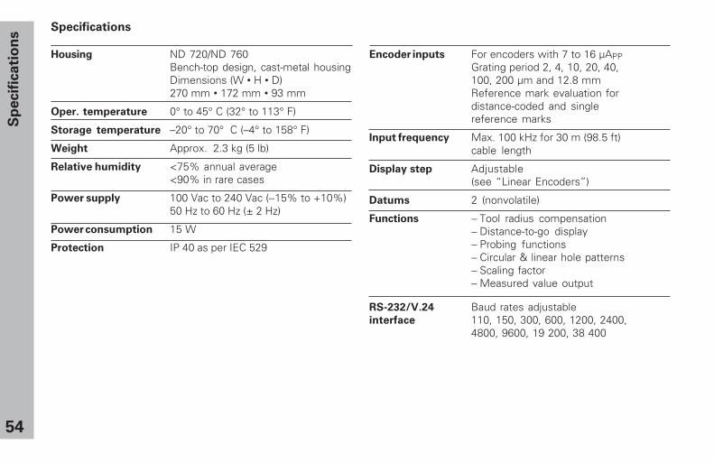
Specifications
Housing ND 720/ND 760Bench-top design, cast-metal housingDimensions (W • H • D)270 mm • 172 mm • 93 mm
Oper. temperature 0° to 45° C (32° to 113° F)
Storage temperature –20° to 70° C (–4° to 158° F)
Weight Approx. 2.3 kg (5 lb)
Relative humidity <75% annual average<90% in rare cases
Power supply 100 Vac to 240 Vac (−15% to +10%)50 Hz to 60 Hz (± 2 Hz)
Power consumption 15 W
Protection IP 40 as per IEC 529
Encoder inputs For encoders with 7 to 16 µAPPGrating period 2, 4, 10, 20, 40,100, 200 µm and 12.8 mmReference mark evaluation fordistance-coded and singlereference marks
Input frequency Max. 100 kHz for 30 m (98.5 ft)cable length
Display step Adjustable(see “Linear Encoders”)
Datums 2 (nonvolatile)
Functions − Tool radius compensation− Distance-to-go display− Probing functions− Circular & linear hole patterns− Scaling factor− Measured value output
RS-232/V.24 Baud rates adjustableinterface 110, 150, 300, 600, 1200, 2400,
4800, 9600, 19 200, 38 400
Sp
ecif
icati
on
s
55
2409.45"
562.
205"
210 ± 0.28.268 ± .008"
15.6"
8.32"
4.5.18"
120
+ 0
.54.
73 +
.02"
38 ± 0.51.5 ± .02"
20°
923.622"
4.5.18"
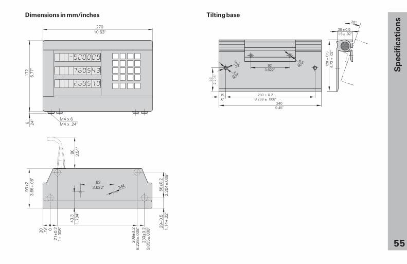
Tilting base
Sp
ecif
icati
on
s
Dimensions in mm/inches
341 696-22 · SW246 271-06 · 15 · 9/2000 · F&W · Printed in Germany · Subject to change without notice
HEIDENHAIN (G.B.) Limited200 London Road, Burgess HillWest Sussex RH15 9RD, Great Britain{ (01444) 247711| (01444) 870024
�������� �� �� ������������������� ��� ��������������������������������� ��� ��� �� ������� ��� ��� �� ��� ����� ��� �!� ��� ��
� ��� !"� ��� ��� �� �����"�#"� $%&���' ( ��� ��� �� ����������� ��� ��� �� ��������� �����' (!� ��� ��
���)���***�� ��� ��