USER’S MANUAL - OFS
94
FTS-B491 HANDHELD SINGLE FIBER FUSION SPLICER USER’S MANUAL Issue 2
Transcript of USER’S MANUAL - OFS

FTS-B491
HANDHELD SINGLE FIBER FUSION SPLICER
USER’S MANUAL
Issue 2

1
Contents
1. Introduction _________________________________________________ 4
2. Safety Information and Instructions _____________________________ 5
2.1 Safety Information _____________________________________________ 5
2.2 Safety Messages ______________________________________________ 5
2.3 WARNINGS and CAUTIONS _____________________________________ 6
2.4 Power Requirements __________________________________________ 11
2.5 Toxic Hazards ________________________________________________ 11 2.5.1 Incineration ______________________________________________________ 11 2.5.2 Acidic or caustic compounds ________________________________________ 12 2.5.3 Physical damage _________________________________________________ 12
3. Getting Started ______________________________________________ 13
3.1 Unpacking and Initial Inspection ________________________________ 13
4. Operating Specifications and Components ______________________ 14
4.1 Specifications ________________________________________________ 14
4.2 Components _________________________________________________ 15 4.2.1 Standard Components _____________________________________________ 15 4.2.2 Optional Components ______________________________________________ 15
4.3 Optional Accessories _________________________________________ 16
4.4 Recommended Consumable ____________________________________ 16
5. External Description _________________________________________ 17
5.1 Main Body ___________________________________________________ 17
5.2 Operating Keys and Status LED _________________________________ 18 5.2.1 Operating Keys ___________________________________________________ 18 5.2.2 LED Indicators ___________________________________________________ 19 5.2.3 Buzzer __________________________________________________________ 19
5.3 Heater ______________________________________________________ 19
5.4 Screens _____________________________________________________ 20 5.4.1 Ready Screen ____________________________________________________ 20 5.4.2 Screen during Splice _______________________________________________ 20 5.4.3 Status Icons _____________________________________________________ 21 5.4.4 Menu Screen ____________________________________________________ 22
6. Basic Operation _____________________________________________ 23
6.1 Preparations for Power Supply _________________________________ 23 6.1.1 Connecting the power cable to AC adapter _____________________________ 23 6.1.2 Charging the Battery _______________________________________________ 23 6.1.3 Turn Splicer ON and OFF ___________________________________________ 24

2
6.2 Load programs _______________________________________________ 25 6.2.1 Fusion Program __________________________________________________ 25 6.2.2 Heater Program __________________________________________________ 26 6.2.3 Selecting the Operating Language ____________________________________ 28
7. Fusion Splicing _____________________________________________ 29
7.1 Basic Splicing _______________________________________________ 29 7.1.1 Arc Check _______________________________________________________ 29 7.1.2 Preparing Fiber ___________________________________________________ 32 7.1.3 Loading the Fiber _________________________________________________ 34 7.1.4 Fusion Splicing ___________________________________________________ 36 7.1.5 Splicing Defects __________________________________________________ 39 7.1.6 Removing the Spliced Fiber _________________________________________ 40 7.1.7 Reinforcing the Fusion Splice ________________________________________ 40
8. Programming Guide _________________________________________ 43
8.1 Programming Function and Menu _______________________________ 43
8.2 Program Edit ________________________________________________ 46 8.2.1 Setting __________________________________________________________ 47 8.2.2 Detail Setting ____________________________________________________ 48 8.2.3 Default _________________________________________________________ 48 8.2.4 Copy ___________________________________________________________ 49 8.2.5 Delete __________________________________________________________ 49 8.2.6 Edit Comment ____________________________________________________ 50 8.2.7 Parameter table __________________________________________________ 51
8.3 History ______________________________________________________ 54 8.3.1 Splice data ______________________________________________________ 55 8.3.2 Arc Check History _________________________________________________ 58 8.3.3 Image Capture ___________________________________________________ 59
8.4 Tool ________________________________________________________ 60 8.4.1 Machine Check ___________________________________________________ 61 8.4.2 Fiber Measuring __________________________________________________ 62 8.4.3 Environment _____________________________________________________ 63 8.4.4 Manual Splicing ___________________________________________________ 64 8.4.5 Image Capture ___________________________________________________ 65 8.4.6 Fiber Edge Inspection ______________________________________________ 66 8.4.7 Sleeve Shrink Adjustment ___________________________________________ 67
8.5 Setting ______________________________________________________ 68 8.5.1 Parameter _______________________________________________________ 70 8.5.2 Counter _________________________________________________________ 77 8.5.3 Clock ___________________________________________________________ 78 8.5.4 About Machine ___________________________________________________ 78
8.6 Shortcut ____________________________________________________ 78
8.7 Maintenance _________________________________________________ 79

3
9. Maintenance and Handling Instructions _________________________ 80
9.1 Error Messages ______________________________________________ 80
9.2 Maintenance _________________________________________________ 83 9.2.1 Arc Check _______________________________________________________ 83 9.2.2 Electrode Maintenance _____________________________________________ 83 9.2.3 Cleaning the V-grooves_____________________________________________ 86 9.2.4 Cleaning V-groove and Fiber Clamps __________________________________ 86 9.2.5 Cleaning the Fiber Holder ___________________________________________ 87
9.3 Backup Battery _______________________________________________ 88
9.4 Storing and Shipping __________________________________________ 88
9.5 Claims and Repackaging ______________________________________ 89
9.6 Return Shipments to Furukawa Electric Co. _______________________ 89 9.6.1 Removing Battery _________________________________________________ 90 9.6.2 Installing Battery __________________________________________________ 90
10. Option ___________________________________________________ 91
10.1 Cooling Tray: CTX-02 __________________________________________ 91
10.2 Cleaning Brush: VGC-01 _______________________________________ 91
10.3 Hard Carrying Case: HCC-03 ___________________________________ 91
10.4 Spare Battery: S946 ___________________________________________ 91
11. Recycling and Disposal ____________________________________ 92

4
1. Introduction
The FITEL NINJA NJ001 is a compact designed fusion splicer.
This Fusion Splicer splices single fibers. After setting the prepared fibers,
NJ001 automatically feeds the fiber ends and inspects their cleave
condition and axis offset. Then the NJ001 discharges the arc to melt the
glass and butts the end together. The NJ001 has the heater applied for
40mm and 60mm protection sleeves for reinforcing the spliced fiber.
The NJ001 can be powered by the AC adaptor and Battery. The Battery is
made of Li-polymer cells and is charged by the NJ001 body.

5
2. Safety Information and Instructions
This manual contains complete operating and maintenance instructions for
the NJ001 Fusion Splicer. Please review this manual carefully before
operating.
2.1 Safety Information
The following safety instructions must be observed during NJ001 fusion
splicer operation, serviced or repaired. Failure to comply with any of these
instructions or with any precaution or warning contained in the User’s
Manual is in direct violation of the standards of design, manufacture and
intended use of the instrument. Furukawa Electric Co., Ltd. assumes no
liability for the customer’s failure to comply with these safety
requirements.
2.2 Safety Messages
The following messages may appear in the User’s Manual. Please observe
all safety instructions that are associated with the message.
Refer to the User’s Manual for instructions on handling and operating the instrument safely.
WARNING
The procedure can result in serious injury or loss of life if not carried out in proper compliance with all safety instructions. Ensure that all conditions necessary for safe handling and operation are met before proceeding.
CAUTION
The procedure can result in serious damage to or destruction of the instrument if not carried out in compliance with all instructions for proper use. Ensure that all conditions necessary for safe handling and operation are met before proceeding.

6
Please contact Furukawa Electric Co., Ltd. or your local representative with
any questions relating to any subject described within this manual.
In no case will Furukawa Electric Co., Ltd. be liable to the buyer, or to any
third parties, for any consequential or indirect damage which is caused by
product failure, malfunction, or any other problem.
2.3 WARNINGS and CAUTIONS
WARNING The power cord supplied with this equipment must be connected to a power socket, which provides a reliable protective ground. Or, ground it with the Ground terminal on the fusion splicer. Use only the cords attached to the fusion splicer. Connecting inappropriate cords or extending the cords may cause them to heat up abnormally and may cause fire. This product contains a Lithium Cell. The device is identified by a warning label. Do not dispose of in fire. Disposal of this device must be carried out by qualified personnel. Never touch the electrodes when the fusion splicer is powered on. Doing so may cause electrical shock. Warning symbol is placed on the windshield for notification. Do not operate the fusion splicer without electrodes. Do not disassemble the instrument except as described in the maintenance section of this manual. The fusion splicer contains no user serviceable parts. Warranty on this product will be void f any of the potted nuts are disturbed. Avoid soaking the fusion splicer with water. Doing so may cause fire, electrical shock or malfunction.

7
WARNING Do not use inappropriate input voltage. Doing so may cause fire, electrical shock or malfunction. Do not insert or drop any metal or any flammable material into the main body through any aperture. Doing so may cause fire, electrical shock or malfunction. Avoid direct skin contact with the heating portion. This may cause burn or injury. Warning symbol is placed on the lid of the protection sleeve heater for notification. Do not remove the panels of the fusion splicer. Some parts generate high voltage. Removing the panels may cause electrical shock. If abnormal sounds or extra high temperatures are observed, turn off the power, disconnect the power cord, remove the battery from the fusion splicer, and contact Furukawa Electric Co., Ltd. or your local representative. Continuing to operate under these conditions may cause fire or electrical shock. Do not use a damaged power cord where the inner cable is exposed or severed. Doing so may cause fire or electrical shock. If water is spilled into the fusion splicer, turn off the power switch, disconnect the power cord, remove the battery, and contact Furukawa Electric Co., Ltd. or your local representative. Continuing to operate under these conditions may cause fire or electrical shock. If smoke or strange smells are observed, turn off the power switch, disconnect the power cord, remove the battery, and contact Furukawa Electric Co., Ltd. or your local representative. Continuing to operate under these conditions may cause fire, electrical shock or malfunction. If the fusion splicer is dropped and damaged, turn off the power switch, disconnect the power cable, remove the battery, and contact Furukawa Electric Co., Ltd. or your local representative. Continuing to operate may cause fire or electrical shock.

8
WARNING Do not look into a fiber with naked eye during operation. Wearing a protection glass is recommended. STOP using the fusion splicer when problems are experienced with the protection sleeve heater. Turn off the power immediately, disconnect the power cord, remove the battery, and contact service center. Do not use a gas spray to the splicer. The hazardous gas may come out by electric discharge. It may cause a fire and machine failure. The NJ001 can be used after following tests: Drop resistance – 76cm drop from 5 different angles. Water
resistance – IPX2 rating drip proof (exposed to 3mm/min drip for 10 min with 15° tilt). Dust resistance – IP5X rating dust proof (exposed to dust particles with a diameter of 0.1 to 25µm for 8 hours) Above tests were performed at Furukawa Electric laboratories and do not guarantee that the machine will not be damaged when subjected to these conditions.
CAUTION Do not place the fusion splicer on an unstable or inclined surface. There is a possibility that the fusion splicer will fall and cause injury. Disconnect all cords when moving the fusion splicer. Failure to do so may damage the cords which may cause fire or electrical shock. Do not place the cords around any heating instrument. Doing so may damage the cords which cause fire or electrical shock. Do not connect or disconnect cords with wet hands. Doing so may cause fire or electrical shock. Do not pull the cord to disconnect. Doing so may damage the cords which may cause fire or electrical shock. Hold the plug portion and disconnect the cord.

9
CAUTION Do not put heavy items on the cords. Doing so may damage the cords which may cause fire or electrical shock. Do not modify the cords and do not over-bend, over-twist, or over-stretch the cords. Doing so may cause fire or electrical shock. Ensure that the cords are disconnected and the batteries are removed from machine’s main body when storing the fusion splicer. Never use aerosol dust cleaners or alcohol-based solvents to clean the electrodes. Non oil-based solvents should be used to clean the optical lenses. Store the fusion splicer in a cool dry place. When the temperature of the splicer body is different from the operating temperature limit extremely even if the environment temperature is in the operating temperature limit, please use after the temperature of the splicer body near the operating temperature. Or, the splicer might not work normally.
The battery is made of Li-polymer battery cells. Refer to following safety
instructions on handling and operating the Battery safety.
CAUTION Do not dispose the Battery in fire, or leave the Battery near a high-temperature object. Doing so may cause fire or explosion. Do not short-circuit the recharging connector or the output terminal for splicer. Doing so may cause fire by generation of heat. Charge the S946 battery by NJ001. If charging by other equipment that is not suitable for charging S946 battery, it may cause fire.

10
CAUTION Avoid soaking the Battery with water. Doing so may cause fire or electrical shock. Do not disassemble the Battery. Avoid damage by dropping or heavy shock. Doing so may cause fire or electrical shock. If inner cells rupture and electrolytic solution leaks outside, it may cause inflammation to your skin or eyes. Disposal of used Battery must be carried out according to disposal established by Law. For instructions, contact Furukawa Electric Co., Ltd. or your local representative. Immediately after the battery has been charged it may have a high temperature. Take care of handling the Battery.
NOTES
This symbol mark is for EU countries only. This symbol mark is according to the directive 2006/66/EC Article 20 Information for end-users and Annex II. This symbol means that batteries and accumulators, at their end-of-life, should be disposed of separately from your household waste. If a chemical symbol is printed beneath the symbol shown above, this chemical symbol means that the battery or accumulator contains a heavy metal at a certain concentration. This will be indicated as follows: Hg: mercury (0.0005%), Cd: cadmium (0.002%), Pb: lead (0.004%) In the European Union there are separate collection systems for used batteries and accumulators. Please, dispose of batteries and accumulators correctly at your local community waste collection/recycling centre. Please, help us to conserve the environment we live in!

11
2.4 Power Requirements
The NJ001 fusion splicer can also operate using AC power with the S978
AC adapter with AC power source that supplies between 100-240 V at a
frequency of 50-60 Hz. The S946 battery is charged by NJ001 through the
S978 AC adapter
WARNING To avoid the risk of injury or death, ALWAYS observe the following precautions before initializing the NJ001 fusion splicer. � If using a voltage-reducing auto-transformer to power the
NJ001 fusion splicer, ensure that the common terminal connects to the grounded pole of the power source.
� Use only the type of power cord supplied with the NJ001 fusion splicer.
� Connect the power cord to a power outlet equipped with a protective ground contact only (never connect to an extension cord that is not equipped with this feature).
� Willfully interrupting the protective ground connection is prohibited.
2.5 Toxic Hazards
The NJ001 fusion splicer presents no toxic hazards (under normal
conditions of use, storage, and handling). However, under the following
conditions, certain precautions are necessary.
2.5.1 Incineration Some of the electronic components included in the assembly are
constructed with resins and other chemicals that produce toxic fumes
during incineration.

12
2.5.2 Acidic or caustic compounds Some of the electronic components included in the assembly, particularly
electrolytic capacitors, contain acidic or caustic compounds. In the event
that a damaged component comes in contact with the skin, wash the
affected area immediately with cold water. In the event of eye
contamination, wash thoroughly with a recognized eye-wash and seek
medical assistance.
2.5.3 Physical damage Some of the components used in the assembly may contain very small
quantities of toxic materials. There is a remote possibility that physically
damaged electronic components may present a toxic hazard. As a general
precaution, avoid unnecessary contact with damaged electronic
components, and arrange for disposal in accordance with local regulations.

13
3. Getting Started 3.1 Unpacking and Initial Inspection
1. Inspect the shipping container for any indication of excessive shock to
the contents.
2. Remove the NJ001 carrying case from the shipping container, and open
the case.
3. Ensure that the carrying case is right side up before opening. (It applies
in the package form with the carrying case.)
4. Inspect the contents to ensure that the shipment is complete.
5. Lift the NJ001 fusion splicer out of the carrying case, and place the
instrument on a flat, smooth surface.
6. Visually inspect the NJ001 fusion splicer and all accompanying
components for structural damage that may have occurred during
shipping.
Immediately inform Furukawa Electric and the carrier, if the contents of the
shipment are incomplete, or if any of the NJ001 fusion splicer components
are damaged, defective, or if the NJ001 fusion splicer does not pass the
initial inspection.
Protection sheet is pasted on the surface of LCD cover, the surface of the
switch panel, and the surface of the label. Please peel off before using
NJ001.
WARNING To avoid electrical shock, do not initialize or operate the NJ001 fusion splicer if it bears any sign of damage to any portion of its exterior surface, such as the outer cover or panels.

14
4. Operating Specifications and Components 4.1 Specifications
The specifications of each splicer are referred the following table.
Item Specification and Features Fiber type*1 SM / MM / DS / NZDS Fiber count Single Fiber Only Coating diameter 0.25, 0.9mm Clad diameter 0.125mm Applicable sleeve length 40mm, 60mm Power DC:11 - 21V
AC:90 - 265V 50/60Hz (AC Adaptor) Weight Main Body: 970g (Including Battery) Power Consumption Max: 39W Normal operation: 5W Environmental Conditions
Operation Temperature: -10 - +50 °C Humidity: Below 90%(No condensation)
Storage Temperature: -40 - +60 °C Humidity: Below 95%
Average Splice Loss*2 SMF: 0.05 dB, MMF: 0.03 dB DSF: 0.08 dB, NZDS: 0.08dB
Typical Splicing Time 13s Typical Heating Time*3
(in the AC Adaptor use) 17s :40mm sleeve*4 (Pre-heating mode) 20s :60mm sleeve*4 (Pre-heating mode) 31s :S922 40mm sleeve / S921 60mm
sleeve (Regular mode) Program Number Available Splice: 150 / Heat: 30 Maximum Number for Data Storage
Splice: 1,500 / Fiber Image: 24
Input/Output Terminals Data Input/Output:USB 2.0 *1: Applied to ITU-T standard *2: Tested in a laboratory environment with similar fibers. Not guaranteed results. *3: In the battery use, the heating time might be longer than typical heating time.
The heating time might be longer depending on the environment too. *4: The heating time might be longer depending on the sleeves.

15
4.2 Components
4.2.1 Standard Components The NJ001 Fusion Splicer comes with the following standard equipment. Be
sure to confirm their presence before starting any operation. The
component is difference by ordering number.
Components Model Number QTY NJ001 Main Body NJ001 1
Battery Pack(Built-in) S946 1 AC Adapter S978A 1 AC Cable Cord - 1 Spare Electrodes ELR-01 1 Electrode Sharpener D5111 1 Cleaning Brush VGC-01 1 Hard Carrying Case HCC-03 1 Manual UMC-01 1 Quick Reference Guide FTS-B492 / FTS-B495 1
4.2.2 Optional Components Components Model Number QTY
Cooling Tray CTX-02 1 Spare Electrodes ELR-01 1 USB Cable USB-01 1 Battery Pack S946 1 Cleaning Brush VGC-01 1 AC Adapter S978A 1 AC Cable Cord - 1 Electrode Sharpener D5111 1 Fiber Holder for 250um S712S-250 1pair Fiber Holder for 500um S712S-500 1pair Fiber Holder for 900um S712S-900 1pair

16
4.3 Optional Accessories
Contact Furukawa Electric Co., Ltd. or your local representative for a more
detailed specification.
� S210 Stripper
� S218R Hot Stripper
� S326 High Precision Cleaver
� S921 60mm Splice Length Protection Sleeves for Single fiber
� S922 40mm Splice Length Protection Sleeves for Single fiber
� S924 40mm Splice Length Protection Sleeves for Ribbon fiber
4.4 Recommended Consumables
Keep a supply of the following items with the NJ001 fusion splicer at all
times.
� Tweezers
� Protective eye glasses
� Denatured alcohol
� Lint-free tissues or swabs
� Container for disposal of scrap fiber

17
5. External Description 5.1 Main Body
LCD monitor
Battery cover
Operating key
Wind shield Protection sleeve heater
DC Power port
USB mini-B port
V-Groove Fiber clamp
Electrode

18
5.2 Operating Keys and Status LED
5.2.1 Operating Keys
Indicator Name Main Functions
Start
Start/Pause/Restart the splicing process.
Function 1
Selecting the function(s) shown on left bottom corner of LCD.
Function 2
Selecting the function(s) shown on right bottom corner of LCD.
Up
Move upward/Increase value/Add additional arc
Down
Move downward/Reduce value
Left
Move left
Right
Move right
Heating
Start heating/Stop heating
Power
Turn on/off the power

19
5.2.2 LED Indicators Indicator Name Color Main Functions
Power LED Green
Lit : Tuned on Blinking : Sleep mode
Heater LED Red
Lit : During heat Blinking : During cool
Charge LED
Charge Lit: During charge Blinking: Error
5.2.3 Buzzer
A buzzer will ring whenever any key is pressed. In addition, the following
buzzer patterns indicate status of operation.
� Operating key: One beep
� Completing machine reset: One beep
� Error occurred: Three beeps
� Splicing finished: A series of beeps
� Saving data: Two beeps
� Heating process finished: One long beep 5.3 Heater
The right clamp of the heater is replaceable to heat the SOC connector. Do
not remove this clamp if unnecessary, because the small pin falls out.
Replaceable
Clamp

20
5.4 Screens
5.4.1 Ready Screen Once the NJ001 fusion splicer is powered up and initialized, the “Ready”
screen is displayed.
5.4.2 Screen during Splice Fiber Images
X from front camera and Y from back
camera. X and Y views can be
switched.
One fiber image is displayed in the
center of screen.
Pop-up Window
Pops up when new functions are
selected. Also, shows warning and
error messages.

21
5.4.3 Status Icons
Type Icon Content
Power
Using external power.
Using internal battery. The level of battery is displayed in percentage. The lamp will start to flash when the level is very low.
No battery. Charging battery.
Backup Battery warning
This icon will be displayed when back-up battery (for storing parameters and data) is very low.
Heater Status
Blue: Ready Mode Red/Yellow: Heating Mode Cooling Mode * Error Occurring
Running Mode
Splicing is triggered by closing the wind shield. Splicing process goes on until the end of splicing. Splicing process pauses once before arc discharge. Splicing process pauses at each sub-step.
Splicing is triggered by pressing the Start key. Splicing process goes on until the end of splicing. Splicing process pauses once before arc discharge. Splicing process pauses at each sub-step.
Semi-Auto mode. The fiber is loaded to the center by closing windshield, and stops temporarily. Splicing is triggered by pressing the Start key.
Data Output Various measurement and calculation information is
shown on the fiber image area. *) The cooling fan will temporarily pause during splicing, but the icon will remain on cooling mode. After splicing has finished, the cooling fan will go on again if the temperature is still high.

22
5.4.4 Menu Screen
Press ◄ ► and ▲ ▼ to access the desired menu and the pointed menu
pop-ups to a large icon. Press Enter to select the menu.
Function keys are provided to initiate current available functions displayed
above the function keys.
Function Menu
Function Keys Press to select the corresponding Function Menu

23
6. Basic Operation 6.1 Preparations for Power Supply
6.1.1 Connecting the power cable to AC the adapter Connect the AC adaptor to the DC
Power port of the Splicer, and plug
the AC adaptor into an AC outlet.
6.1.2 Charging the Battery After connecting the power cable to AC adapter and plugging the power
cable into AC outlet, the charging process starts.
(When splicing, the charging process stops temporarily. The charging time
will be longer. The charging time will vary depending on the remaining
power level of battery.)
S946 battery is lithium polymer type rechargeable battery; it can be recharged at any time, regardless if it is fully empty or still with some residual power. If storing the battery for a long time, the power level becomes very low caused by self-discharging and the battery may be degraded. Be sure to recharge the battery at least every 2 months even when not in use.
AC Adapter DC Power port
Charge Icon
Charge LED

24
It is possible that the battery could not be fully charged, if moving the battery from a cold place (<5°C) to a warm place (around 20°C) and then immediately charging it. In this case, make sure the battery is in the new environment for a short while to equalize the temperature, and then charge the battery. When charging the battery, the room temperature must be in the range of 5 - 40°C.
6.1.3 Turn Splicer ON and OFF Keep pushing power key (for about 2 seconds) to turn on/off.
Turning ON power
The opening message will
appear on the LCD screen for a
short while, before the ready
screen showing up.
Turning OFF power
The LCD screen is turned off.
The power supply cuts after all
motors perform the reset operation.
Power Key

25
6.2 Load programs
Install appropriate programs before operation. The NJ001 fusion splicer
already has pre-defined programs installed for major fiber types and
protection sleeves. Select the program for fusion and heat, or edit and
store a new program.
6.2.1 Fusion Program Install an appropriate fusion program for specific fibers to be spliced.
1. Press Menu to call the menu screen.
2. Select “Fusion PRGM” and press Enter, and the Fusion PRGM screen is
displayed.
3. Select “Recent Programs” to select from the programs recently used, or
“All Programs” to select from all the programs installed.
4. Select the proper program by pressing ▲ ▼ and press Select. A
comment of the pointed program is displayed by pressing ►, and will
disappear by pressing ◄.

26
The NJ001 Fusion Splicer is installed with the factory-set Fusion Programs
as follows.
No. Mode Comment Description 1 SM1 SINGLE MODE Standard single SM fiber 2 MM1 MULTI MODE Standard single MM fiber 3 DS1 DISPERSION SHIFT Standard single DS fiber 4 NZ1 NON ZERO DS Single None-Zero DS fiber 5 G657 G657 Single Bend-Insensitive SM fiber
6.2.2 Heater Program 1. Press Menu to display the menu screen.
2. Select heater program and press Enter, and the “Heater PRGM” screen
is displayed.
3. Select the proper program by pressing ▲ ▼ and press Select .
4. Press Escape repeatedly until the ready screen is displayed.

27
The NJ001 Fusion Splicer is installed with the factory-set Heat Programs as
follows.
No. Mode Comment Description 1 40MM S922 Furukawa S922 sleeve (40mm) 2 40MM S922 POWER Furukawa S922 sleeve (40mm) with
pre-heating.* 3 40MM OTHER Other 40mm length sleeve 4 40MM SMOUV
POWER TE connectivity SMOUV-02 sleeve (40mm) with pre-heating.*
5 ---- --- Vacant 6 ---- --- Vacant 7 60MM S921 Furukawa S921 sleeve (60mm) 8 60MM S921 POWER Furukawa S921 sleeve (60mm) with
pre-heating * 9 60MM OTHER Other 60mm length sleeve 10 60MM SMOUV
POWER TE connectivity SMOUV-01 sleeve (60mm) with pre-heating.*
11 60MM CONTINUOUS Heating continuously for 60mm 12 ---- --- Vacant 13 40MM S924 Furukawa S924 sleeve (40mm) 14 40MM S924 POWER Furukawa S924 sleeve (40mm) with
pre-heating * 15 40MM S927B Furukawa S927B sleeve (40mm) 16 40MM S927B POWER Furukawa S927B sleeve (40mm) with
pre-heating * 17 MINI S928A Furukawa S928A sleeve
(20/25/30mm length) 18 MINI OTHER Other 20/25/30mm length sleeve 19 :
27
28 60MM S921DC Furukawa S921DC sleeve (60mm) 29 --- SOC 20mm length sleeve for SOC 30 --- CURL REMOVE Removing giber curl
*) Pre-heating warms the heater to shorten the heating time in advance, before the heating program starts. Pre-heating starts after arc discharge and heating process.
28
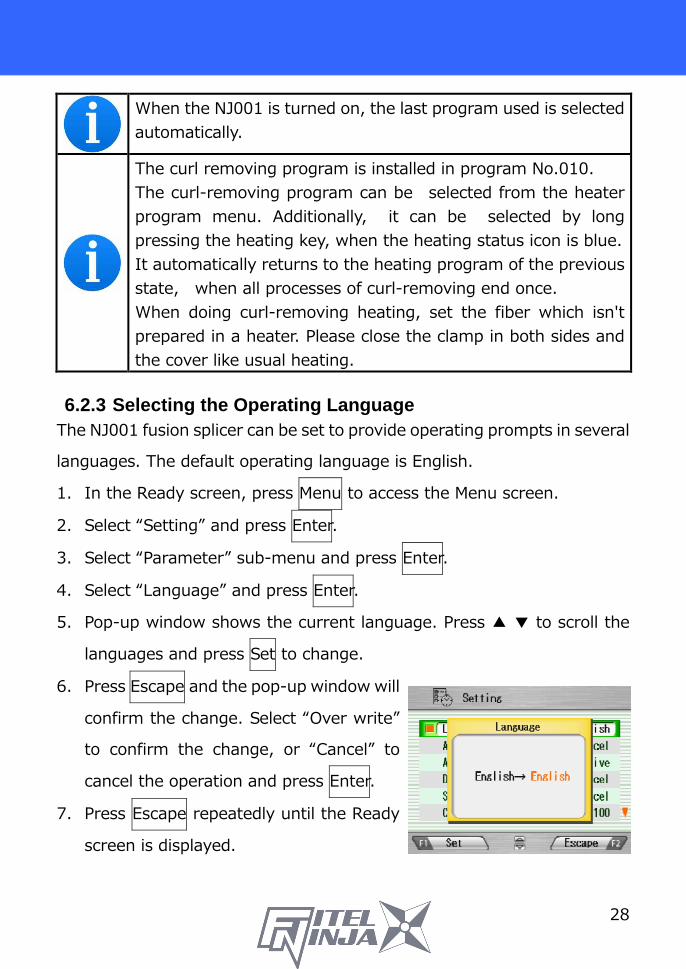
When the NJ001 is turned on, the last program used is selected automatically.
The curl removing program is installed in program No.010. The curl-removing program can be selected from the heater program menu. Additionally, it can be selected by long pressing the heating key, when the heating status icon is blue. It automatically returns to the heating program of the previous state, when all processes of curl-removing end once. When doing curl-removing heating, set the fiber which isn't prepared in a heater. Please close the clamp in both sides and the cover like usual heating.
6.2.3 Selecting the Operating Language
The NJ001 fusion splicer can be set to provide operating prompts in several
languages. The default operating language is English.
1. In the Ready screen, press Menu to access the Menu screen.
2. Select “Setting” and press Enter.
3. Select “Parameter” sub-menu and press Enter.
4. Select “Language” and press Enter.
5. Pop-up window shows the current language. Press ▲ ▼ to scroll the
languages and press Set to change.
6. Press Escape and the pop-up window will
confirm the change. Select “Over write”
to confirm the change, or “Cancel” to
cancel the operation and press Enter.
7. Press Escape repeatedly until the Ready
screen is displayed.

29
7. Fusion Splicing 7.1 Basic Splicing
7.1.1 Arc Check Fusion splicing is used to melt the glass of two optical fiber ends by arc
discharging, and joins them together by butting the ends together. Fibers
melt or fuse at different temperatures. It is necessary to adjust the arc
power in order to ensure optimum splicing results. As well, electrode wear,
environmental conditions, e.g., temperature, humidity, altitude, can affect
the splicing results.
The arc check function inspects the arc power, and adjusts it to a proper
one. At the arc check, the splicer melts the fiber ends not to join together,
but to check the melting condition
The arc check should be performed as follows. In addition, when splice
errors occur continuously, perform the arc check to check whether Arc
Power is correct or not.
� At the beginning of daily operation
� When the environmental condition has changed considerably
� After replacing or cleaning electrodes 1. Open the windshield and load fibers. Ensure that the fibers are
properly stripped, cleaned and cleaved. Refer to “7.1.2 Preparing the
Fiber” for detail.
2. Close the windshield.
3. Select “Arc Check” in the menu screen and
press Enter.
4. The NJ001 fusion splicer automatically
feeds the fibers and discharges an arc.

30
� During the arc discharge, the fiber feeding motors of the NJ001
fusion splicer remain idle, preventing the fiber ends from butting.
As a result, the fiber ends melt back.
� The arc check function inspects how far the fibers melt back and the
centered position of the fiber. If the arc check results are good, the
message “RESULT: OK” is displayed in the pop-up window. Press
OK to return to the Menu screen.
� If the results are negative, “RESULT: NG Try again” is displayed.
Press Retry and the machine will automatically adjust the arc power,
and then return to the Menu screen.
5. If result is NG, repeat the arc check until the new values are acceptable.
It is necessary to remove the fibers and prepare them again with a
new cleave. If unsatisfactory results are obtained after 4 arc check
attempts, inspect the electrodes for wear or damage, and replace
them if necessary.

31
� A visual arc check can be made by viewing the arc on the monitor
by pressing ▲. Electrode discharge should produce a straight and
steady arc. Swaying in the arc indicates that the electrodes require
either cleaning or replacing.
� When the “Data Output” in the “Parameter” of “Setting” menu is set
“Active” or “PC”, detailed arc check data are shown in the result.
Pressing Optimize enables automatic adjustment of the arc power,
while Cancel does not adjust or complete the arc check.
� RETREAT AAA(BBB-CCC) AAA: Melt back value BBB: Lowest allowable value CCC: Highest allowable value
� POWER DDD(+EEE)→FFF(+EEE)
DDD: Current arc power EEE: Compensated value for environment changes FFF: Recommended arc power
� CENTER GGG (±HHH)→III
GGG: Current arc center HHH: Allowable range of arc center III: Recommended arc center

32
7.1.2 Preparing the Fiber
Splice loss is directly affected by the quality of the fiber preparation. For
best results, ensure that the V-grooves are clean and that the fiber ends
are properly cleaned and cleaved.
Prepare the single fiber according to the following procedure.
1. Insert a splice protection sleeve onto either the right or the left fiber.
2. Strip off a portion of fiber coating by using the fiber stripper. For details,
refer to the manual of the stripper.
3. Wipe the bare fiber with a lint-free tissue soaked with denatured
alcohol.
Please use ethanol of more than 99% of purity for cleaning fiber.
Protection sleeve
Insert
Fiber
Single fiber
Stripper
Cleaning cotton
Bare fiber

33
4. Make sure to use the suited fiber holder according to the diameter of
the fiber coating. Place the fiber in such a manner that the fiber
coatings removal edge matches the holder convex end as below.
In the case of splicing with 5mm cleaving length for NJ001, clean the fiber carefully, especially around the ragged edge of the coating to remove the residue. If the residue remains at edge and such fiber is put into the V-groove, it may cause the axis offset subsequently.
5. Cleave the fiber so that 10mm length of bare fiber extends past the
fiber coating. Refer to the manual of the cleaver for details.
� Do not clean the bare fiber after it has been cleaved.
� Do not let the bare fiber tip come in contact with any surfaces.
� Do not look into a fiber with the naked eye during operation. Wearing
protection glasses is recommended.
Fiber holder for single fiber
Single fiber
Holder convex end
Fiber coating edge
Bare fiber
10mm 13mm

34
7.1.3 Loading the Fiber
1. Open the windshield.
2. Set the fiber holder by inserting the hole on the fiber holder to the pin
on the fusion splicer as shown in the picture. Be sure that nothing
touches the bare fiber tip.
3. Make sure the bare fiber is placed right on the V- groove. If not, remove
the fiber holder and set again.
4. Repeat the process for other fiber holders.
5. Close the windshield, and the ready screen is displayed.
Do not slide the tips of the fiber ends through the V-groove tracks.
WARNING When placing fibers on V-grooves, take care not to break them by hitting them against the V-groove or other parts of the splicer. Broken fiber may get into your eyes.

35
NJ001 fusion splicer has very short V-groove length to accommodate with short cleaving length of fiber. Set the fiber with short cleaving length on to the V-groove, as shown below.
In case of splicing 900µm coating fiber, if the fiber has curls or bendings, it may be difficult to put such fiber on to V-groove as the fiber jumps out from the V-groove. In such case, it may be better to put the fiber edge in a downward direction (flip fiber with 180 degree).
If the fiber has curls or bendings, it may make it difficult to sit properly in the V-groove. Please remove the curls or bending before preparing the fiber, and then place it in the V-grooves.

36
7.1.4 Fusion Splicing 1. Ensure that the “READY” screen is displayed on the monitor.
2. Press to initiate the fusion splicing cycle.
3. The NJ001 fusion splicer performs the following functions automatically.
To pause the NJ001 fusion splicer during any of these functions, press
. The message PAUSE will be displayed on the monitor. To restart the
operation, press again.
� The right and left fiber ends appear on the LCD monitor.
� A cleaning arc is discharged to clean the fiber ends.
� The fibers are set with a gap of about 30 µm between the ends.
� The fibers are inspected for axis offset and cleave condition.
� The electrodes discharge.
� The splice is inspected.
� The splice loss is estimated and displayed on the LCD monitor as
shown in the picture.
37
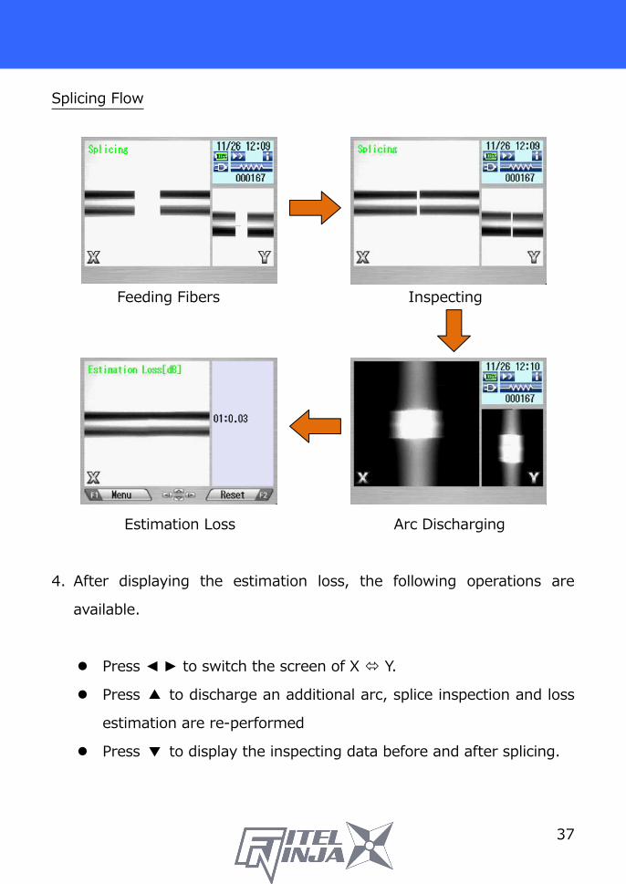
Splicing Flow
Feeding Fibers Inspecting
Estimation Loss Arc Discharging
4. After displaying the estimation loss, the following operations are
available.
� Press ◄ ► to switch the screen of X � Y.
� Press ▲ to discharge an additional arc, splice inspection and loss
estimation are re-performed
� Press ▼ to display the inspecting data before and after splicing.

38
5. While in Pause status, pressing Menu displays options available in the
process. To resume the process, press again.
� Menu: Display the menu screen.
� Zoom: Zoom in the fiber image.
� Capture: Capture the fiber image
and store it with the splice data.
� Field X�Y: Switch the fiber view
between X and Y.
•If the fibers fail the inspections for cleave criteria, the fusion cycle is
paused and an appropriate error message is displayed as below. Press ▼ to
temporarily hide message and check the state of the fiber. Open the
windshield, remove the fibers after READY is displayed and retry the splice
by repeating the entire procedure, starting from the fiber preparation
process. To ignore the error and continue the cycle, press OK and press
Enter.
After splicing, The splicer inspects the splicing state by image processing. However, please also check viewing on the LCD screen.

39
7.1.5 Splicing Defects Defects Possible Cause Action
Bubbling
Wrong fiber type selected
Select the correct Fusion Program, and repeat fusion splicing.
Faulty cleave Repeat fiber preparation and fusion splicing.
Dirty fiber end Repeat fiber preparation and fusion splicing.
Degradation of electrodes
Replace the electrodes.
Bubbling (MMF)
Depending on fiber Increase “Pre_fuse_time” in the Fusion Program (e.g. Increase by 50[msec] )
Not spliced
or
Neck-down
Wrong Fusion Program selected
Select the correct Fusion Program, and repeat fusion splicing.
Faulty cleave Repeat fiber preparation and fusion splicing.
Excessive arc current Perform an arc check, and adjust arc power.
Insufficient fiber feed Adjust the fiber feed amount. Degradation of electrodes
Replace the electrodes.
Thickening
Wrong Fusion Program selected
Select the correct Fusion Program, and repeat fusion splicing.
Excessive fiber feed Adjust the fiber feed amount. Degradation of electrodes
Replace electrodes.
Excessive arc current Perform an arc check, and adjust arc power.
Streak
Wrong Fusion Program selected
Select the correct Fusion Program, and repeat fusion splicing.
Degradation of electrodes
Replace the electrodes.
Weak arc Perform an arc check and adjust arc power, or apply an additional arc.

40
7.1.6 Removing the Spliced Fiber 1. Raise both heater clamps before removing the fiber.
2. Open the windshield. A tension test (1.96N) is performed on the fibers.
3. A buzzer beeps once when the tension test is completed.
4. Open the lid of both fiber holders.
5. Remove the spliced fiber, pulling slightly so that the fiber is taut.
Handle the spliced fiber carefully. Do not twist the fiber.
CAUTION Do not attempt to load fibers while the NJ001 fusion splicer is resetting. Load the fibers only after the reset operation is complete and the READY screen is displayed.
7.1.7 Reinforcing the Fusion Splice 1. Slide the splice protection sleeve over the splice.
2. Place the spliced fiber in the heater – Right-side first – to force the Right
heater clamp to close.
3. Ensure that the splice protection sleeve rests in the middle section of
the heater and that the stainless steel rod in the sleeve faces down.
fiber splice protection sleeve
stainless steel rod heaterstainless steelrod
bare fiber
4. Keeping the fiber taut with the left hand, lower the spliced fiber to force
the left heater clamp to close.

41
If protection sleeve is placed incorrect position during heater cycle, this may cause a shrinking error.
5. Close the heater cover.
6. When the fiber is set and the left clamping is shut, the heat LED turns on
red and the heating starts automatically. (When heater auto start
setting is “0”, press to activate the heater.)
The heating process is displayed in the LCD monitor with status icons as
below. When the heating and cooling operations are completed, a beep
sound is heard.
Type Icon Content
Heater Status
Blue: Ready Mode Red/Yellow: Heating Mode Cooling Mode Error Occurring
� To stop the heating operation (the HEAT LED is lit), press . The
heating stops immediately.
� When the ambient temperature is lower than 10 °C, the heating
time is automatically extended by app. 5 to 20 seconds.
40mm S922 S924 S927B
60mm S921
20mm S928A-20
25mm S928A-225

42
During the heater cycle, do not open the heater clamp or lid. This may cause a shrinking error.
7. Remove the fiber from the heater, and inspect the splice protection
sleeve. normal heating
excessive heating
insufficient heating
WARNING STOP using the fusion splicer when problems are experienced with the protection sleeve heater. Turn off the power immediately, disconnect the power cord, remove the battery, and contact our service center. DO NOT touch the heater element during the heater cycle and right after the heat process is complete. The element is very hot and may burn you.
Decrease the heating temperature.
Extend the heating time.

43
8. Programming Guide 8.1 Programming Function and Menu
To start programming, the user needs to access each function through the
menu screen.
1. Press Menu (function key) to access the Menu screen. The Menu key is
available in the Ready screen and splice screens. When the menu is
displayed in a pop-up screen, select the Menu and press Enter.
2. Menu screen is displayed as shown (in picture to the right). Press
Escape (function key) to return to the previous screen.
The following table is a list of functions available to the operator for
programming and maintenance.

44
Menu Features Contents
Arc Check
Perform arc check
Check previous splicing data, add comment, erase the data or transfer the data to PC.
Tool
Perform a self machine check
Automatically diagnose condition of machine.
Measure fiber
Measure and indicate fiber’s clad diameter, core diameter, core offset between fibers, cleaving angles and/or gap between fibers.
Measure environment condition
Measure and indicate ambient temperature, pressure, as well as heater temperature.
Manually splice fiber
Manually control entire splicing cycle (using the keypad).
Capture image Store, record or erase fiber image
History
Splice Data Check previous splicing data, add comment, erase the data or transfer the data to PC.
Arc Check History
Check arc data, add comment, erase the data or transfer the data to PC.
Image Data Check fiber image, add comment, erase the image or transfer the image to PC.
Program Edit
Edit splicing programs
Change parameter values in the program, adjust inspection criteria for the splicing process or change program name.
Edit heating programs
Change heat temperature, heat duration, and/or program name.

45
Menu Features Contents
Heater PRGM
Select heat program list.
List all available heat programs for fiber reinforcement. User can select any from the list. See “Selecting a Fiber Program” in “Getting Started”.
Fusion PRGM
Select fusion program list
List all available fusion splicing programs. User can select any from the list. See “Changing Fiber Program” in “Getting Started”.
Short Cut
Set up short cut key
Save frequently used screen with short cut key, so user can immediately access desired screen, when necessary.
Setting
Set up parameters
Set up default language, login name, sleep function, splicing start pattern, etc.
Set up counter Get arc discharge times, splice counts. Set up recommended splice counts for the replacement/cleaning of electrodes.
Configure the data indicator
Turn measurement and/or estimation data during the splicing process on/off.
Adjust Date/Time
Adjust the date and time. Change the timer format indicating date and time.
Check machine info
Get machine’s manufacturer S/N, software version.
Maintenance
Replace/Clean electrodes Step-by-step tutorial that illustrates how
to replace/clean the electrodes, clean lens or clean V-grooves & fiber clamps.
Clean lens Clean V-groove & fiber clamp. SOC Reference Guide
Procedure of splicing with ferrule.

46
8.2 Program Edit
1. Select “PRGM Edit” in the Menu screen and press Enter.
2. Select “Fusion” or “Heater” and press Enter.
The following procedures and pictures are for Fusion program editing;
however, the same procedure can be applied to the Heat programs.
3. Stored program list is displayed (as shown in picture to the right).
Comment for highlighted program can be displayed by pressing ►, and
turned off by pressing ◄.
4. Select a program to be modified by pressing Enter and press Menu to
access to pop-up menu. Select a function and press Enter.
� Setting: Modify parameters.
� Detail Setting: Modify detailed parameters.
� Default: Return the parameters to default value.
� Copy: Copy the program and store with a new name.
� Delete: Erase the program from the program list.
� Edit Comment: Edit comment of the program.
47
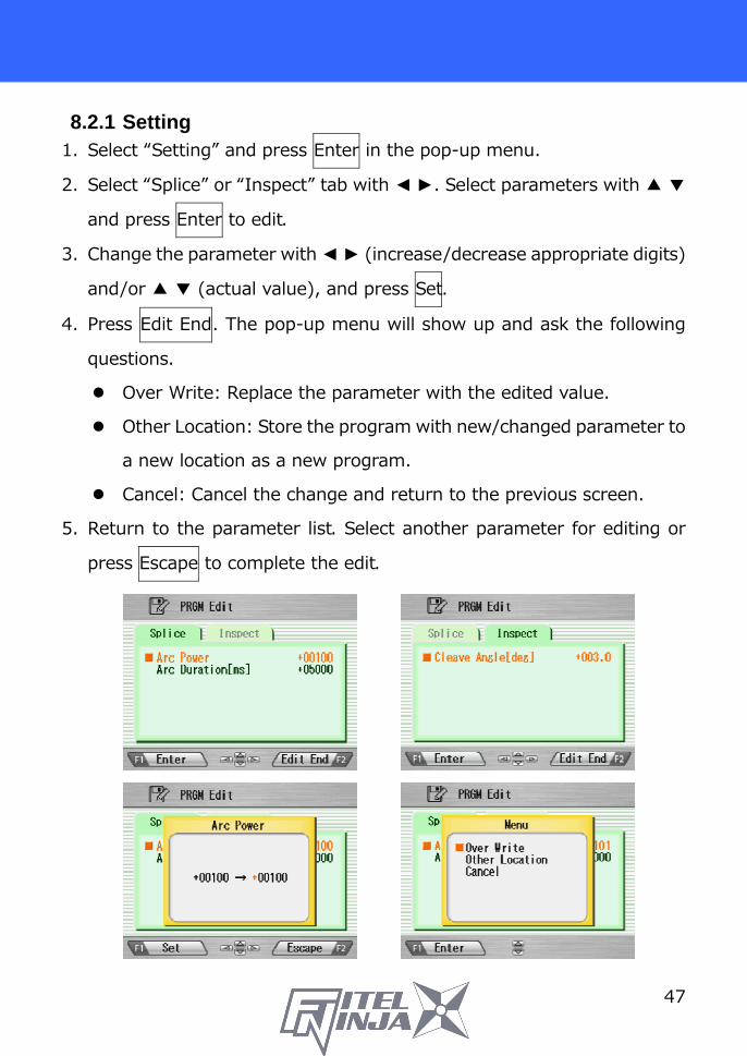
8.2.1 Setting 1. Select “Setting” and press Enter in the pop-up menu.
2. Select “Splice” or “Inspect” tab with ◄ ►. Select parameters with ▲ ▼
and press Enter to edit.
3. Change the parameter with ◄ ► (increase/decrease appropriate digits)
and/or ▲ ▼ (actual value), and press Set.
4. Press Edit End. The pop-up menu will show up and ask the following
questions.
� Over Write: Replace the parameter with the edited value.
� Other Location: Store the program with new/changed parameter to
a new location as a new program.
� Cancel: Cancel the change and return to the previous screen.
5. Return to the parameter list. Select another parameter for editing or
press Escape to complete the edit.

48
8.2.2 Detail Setting 1. Select “Detail Setting” and press Enter in the pop-up menu.
2. A more detailed set of parameters is possible. The setting method is the
same as "Setting".
Press ▲ ▼ : Move one by one item Press : Move to next page
8.2.3 Default Follow the procedures shown below to reset the modified program to the
default parameters.
1. Select “Default” from Menu screen and press Enter in the pop-up menu.
The pop-up message window appears.
2. Press Enter.
3. Select “Yes” and press Enter to reset parameters to default parameters;
or select “No” and press Enter to cancel the operation.

49
8.2.4 Copy Follow the procedures shown below to copy the selected program.
1. Select “Copy” and press Enter in the pop-up menu.
2. Select a new destination for the program. The locations of the factory
pre-installed programs cannot be selected.
3. Press Enter to paste the program.
8.2.5 Delete Follow the procedures shown below to delete the selected program.
1. Select “Delete” and press Enter in the pop-up menu.
2. A pop-up message will be displayed on the screen asking “Delete
Program?”. Press Enter to proceed with the operation.
3. Select “Yes” and press Enter to delete the program; or select “No” and
press Enter to cancel the operation. The factory pre-installed programs
cannot be deleted.

50
8.2.6 Edit Comment Follow the procedure shown below to edit the comment of the selected
program.
1. Select “Edit Comment” and press Enter.
2. The screen shows current comment in the upper window and
characters available for editing in the lower window.
3. Select a character in the lower window with ◄ ► and ▲ ▼. Press Set to
choose the character. The character with red color in the current
comment is replaced with the selected character.
4. Press Escape after new comment is edited.
5. The pop-up menu shows up and asks the following questions
� Over Write: Replace the current comment with the edited one.
� Cancel: Cancel the change and return to the previous screen.
6. Select “Over Write” and press Enter to save edited comment; or select
“Cancel” and press Enter to cancel the operation.
NJ001 splicer can store a maximum of 150 fusion programs.

51
8.2.7 Parameter table Parameter Table for Splice
Parameter Name Min Max Description
1st Arc Start Power 0 200 Starting arc power in 1st arc discharge
1st Arc End Power 0 200 Ending arc power in 1st arc discharge
2nd Arc Start Power 0 200 Starting arc power in 2nd arc discharge
2nd Arc End Power 0 200 Ending arc power in 2nd arc discharge
Cleaning Arc Power Offset -127 128 Additional Arc Power for cleaning
purposes Cleaning Duration 0 32767 Arc duration for cleaning [msec]
Pre-fuse Duration 0 32767 Time between arc starting and fibers first butting [msec]
1st Arc Duration 0 32767 1st arc time duration [msec] 2nd Arc Duration 0 32767 2nd arc time duration [msec] Z Pull Start Time [ms] 0 32767 Time to start to pull back the fiber
[msec] Z Push Distance [µm] 0 32767 Overlapping distance from fibers
first butting position [µm] Z Pull Distance [µm] 0 32767 Pulling back distance from the final
overlapping position [µm]
Re Arc Times [times] 0 255
Allowable numbers for the repeat arc in programmed additional arc mode
Re Arc Duration [ms] 0 32767 Duration of additional arc [msec]
Re Arc Interval [ms] 0 32767 Interval between additional arc and
additional arc [msec] Repeat Arc Power Offset -127 128 Power of additional arc is Arc Power
added by Repeat Arc Power Offset Re Arc Power 0 255 Power of additional arc
Gap [µm] 0 184 Gap for the final position tuning before the splicing [µm]

52
Parameter Table for Splice
Parameter Min Max Description Offset [µm] 0 99.9 Maximum permissible fiber offset [µm] Cleave Angle [deg] 0 90.0 Maximum permissible angle of cleaved
fiber end for splicing to continue [deg]
Loss Limit [dB] 0 15.0 Maximum loss allowed for machine not to give a splicing error [dB]
Gap Difference [µm] 0 99.99 Maximum permissible gap difference
before splicing [µm] Time chart of fusion parameters
Arc power Compensation Table Arc Power Cleaning
Arc Power Fusion Arc
Power Repeat Arc
Power Cleaning Power Offset *1 + 0 0 Repeat Arc Power offset *1 0 0 + Environment Compensation + + + Real Time Arc Control *2 0 + + The items marked with “+” are added at the time of calculating each arc power. *1 This is a parameter of the splicing program, and can be changed. *2 Possible to change to “Active” or “Cancel” in “Setting”. Added when set to “Active”.
Arc Power
1st Arc End Power
0
0
Z Distance Feeding
Gap
Z Push Distance Z Pull Distance
Collision of Fibers
Pre-fuse Time Z Pull Start Time
1st Arc Duration 2nd Arc Duration
Time flow 1st Arc 2nd Arc
2nd Arc Start Power
1st Arc Start Power
2nd Arc End Power

53
Parameter Table for Heater Program
Parameter Min Max Description 1st Heat Temp IN [deg C] 0 280 Temperature of INNER heater for the
first half. 1st Heat Temp OUT [deg C] 0 280 Temperature of OUTER heater for the
first half. 1st Heat Time [sec] 0 300 Operation time of the first half. 2nd Heat Temp IN [deg C] 0 280 Temperature of INNER heater for The
latter half. 2nd Heat Temp OUT [deg C] 0 280 Temperature of OUTER heater for The
latter half. 2nd Heat Time [sec] 0 300 Heating time after 1st heating
Cool Temp [deg C] 0 280 Temperature to arrive at end of cooling process.
Pre Heat temp IN [deg C] 0 280
Temperature of INNER heater for preliminary heating. Preliminary heating temperature before the first half.
Pre Heat temp OUT [deg C] 0 280
Temperature of OUTER heater for preliminary heating. Preliminary heating temperature before the first half.
Pre Heat Time [sec] 0 300
Operation time of preliminary heating after the end of cooling process or before the first half.
Auto Start 0 2
Setting for automatic start function. [0] : Manual start operation. [1] : When fiber set and left clamping is shut, heating start automatically.* [2]: Consecutive heating operation.
Compensation Auto Start 0 30 Expansion time of the automatic
operation. *Do not leave the protection sleeve in a heater after finish of shrinkage. The coating may melt.

54
Time chart of heater parameters
8.3 History
By selecting “History” in the Menu screen, the user can access detailed
splice data, arc check history and image archives; the user can also add
comments to each individual data point. The data also can be transferred/
uploaded to PC or deleted from the memory. 1. In the Menu screen, select the “History” and press Enter.
2. Select “Splice Data” or “Image Data” and press Enter to get the stored
data.

55
8.3.1 Splice data 1. If “Splice Data” is selected, a list of previous splice data is displayed on
the screen.
(As for the history with “*”, the splice image is preserved automatically.)
2. Select a targeted date and press Enter to obtain the details of the data
as shown in the picture.
3. Press ► to display the detail data of each fiber as follows.

56
Data Title Description CMNT Comment of the data, which can be edited.
No. No. 1 is the data for the last splice and the number increases for older splices.
Arc Count Arc Count when splice was performed. Date Date and time for the splice performed.
Env. The environmental temperature and the air pressure, when Splicing was done.
PRGM Name of Fusion Program.
Arc Power Value of the strength of the electric discharge when splicing
Retreat Retreat value in arc check Center Retreat center position in arc check Loss Estimated splice loss AngL Cleave angle of the left fiber AngR Cleave angle of the right fiber Axis Axis offset before splice
Note
Error codes and additional arc memo if any. The data with error is highlighted. L: Estimated loss exceeds the target value S: Streak or bubble at the splice point or not spliced A: Cleave angle exceeds the criteria C: Cleave end face has excessive defects G: Gap difference exceeds the criteria +: Additional arc is applied
4. Press Menu and the pop-up shows available functions. Select desired
function and press Enter to initiate the operation.
� Edit Comment: Edit the Comment of data.
� PC-OUT: Transfer/Uploading the data to PC.
� Delete: Delete the data.
57
Comment Edit
Refer to 8.2.6 for how to edit comment. PC-OUT
When connecting the NJ001 to a PC, install driver software for NJ001 on
your PC. Ask your representative or Furukawa Electric to obtain the driver
software. Follow the procedures shown below to upload the data to PC.
1. Turn on NJ001 and PC.
2. Connect NJ001 to PC with a USB cable.
3. Open the termination emulator such as “HYPER TERMINAL” of windows.
For explanation, this manual uses HYPER TERMINAL of Windows XP.
4. In “Connection Description” screen, name “NJ001” in the box for the
name of new connection and select dial-up icon.
5. Select an appropriate communication port (COM2, for example) from
“Connect To” screen.
6. Cancel the “Port Setting” window.
7. In HYPER TERMINAL menu. Select Transfer then Capture Text.
8. Name TEST for example. Remember the location that TEST will be
stored in. (Default would be C: / Program files/ Accessory/Hypertext.)
Now HYPER TERMINAL is ready for receiving data.
9. Select “PC-OUT” in the pop-up menu of NJ001 and press Enter.
10. Select “Current” for the desired/selected data or “All” for all the
stored data and press Enter. NJ001 will send data through HYPER
TERMINAL to PC and you will see data in the window.

58
Delete
1. Select “Delete” and press Enter.
2. Select “Current” for deleting desired/selected data only or “All Data” for
all the stored data and press Enter. The selected data are then deleted.
� 1,500 splice data entries can be stored on the NJ001. Data older than
1,500 splices are automatically erased.
� When the splice is performed with an additional arc, the data show final
results after the additional arc.
8.3.2 Arc Check History 1. The list of previous arc checks is shown on
the same screen as splice data.
2. Select a targeted time and press Enter to
display the detail of the data as shown in the
picture.
The data displayed are as follows;
Data Title Description CMNT Comment of the data, which can be edited.
No. No. 1 is the data for the last arc check and the number is counted up for older arc checks.
Arc Count Arc count when splice was performed. Date Date and time for the arc check performed. PRGM Name of Fusion Program. Arc Power Value of Arc Power Retreat Value of how far the fibers melt back Center Value for centered position of the melt back

59
3. Press Menu and the pop-up shows available functions. Select desired
function and press Enter to initiate the operation.
� Comment Edit: Edit the Comment of the data.
� PC-OUT: Upload the data to PC.
� Delete: Delete the data.
Follow the same procedure as for Splice Data.
8.3.3 Image Capture 1. The list of captured photos is displayed.
2. Select a photo and press Enter to show the image and data as shown in
the picture.
3. Press Menu and the pop-up shows available functions. Select desired
function and press Enter to initiate the operation.
� Edit Comment: Edit the Comment of the data.
� FULL Screen: Display the image in the full screen size.
� Delete: Delete the data.
Follow the same procedure for splice data.
The data displayed are as follows;
Sample Description 001 SM4 Name of the Fusion Program 00319 Arc Count when splice was performed. Ready Splicing process when the image is captured. X Field/Y Field X or Y image
32 °C 1023hPa Temperature and ambient pressure when splice was performed.
DEFAULT USER Comment

60
8.4 Tool
This menu provides various kinds of utility functions.
1. Select “Tool” in the Menu screen and press Enter.
2. Select a Sub-Menu in the table below and press Enter.
3. Press Escape repeatedly to return to the Ready screen.
Sub-Menu Function Machine Check Perform a self-check of the machine condition.
Fiber Measuring Perform auto or manual inspection of the fiber with regards to clad and core offset, relative eccentricity, gap, tilt and relative cleave angle.
Environment View ambient temperature, pressure, as well as heater temperature.
Manual Splicing Allows operator to manually control entire splicing cycle (using the keypad)
Image Capture Store and delete the fiber image. Fiber edge inspection Measure cleave angle. (Not guaranteed) Sleeve Shrink Adjustment Adjust the shrinking condition of the sleeve.

61
8.4.1 Machine Check 1. A pop-up message prompts the user to
remove the fiber from the machine. Follow
the message and press OK.
2. NJ001 automatically checks for dust in the
camera and verifies the motor movements
(see sample screen to the right).
Pop-up screen then prompts the user to set the fiber in place.
3. Set the fibers on both sides and press to initiate the remaining
check.
4. NJ001 automatically performs the remaining check and a pop-up
message prompts the user to perform an arc check.
5. Press Enter and select “Execute” or “Cancel” to perform the arc check.
In the pop-up screen, press Enter again.
6. After the machine check is complete, the pop-up screen shows “Status
OK”. Press Escape key to finish the check.
7. If the machine fails the machine check, a pop-up screen shows “Status
NG. Call the Service Center”. Please call your representatives or
Furukawa Electric for further assistance.
8. If the arc check fails, pop-up screen shows “Status NG. Remove fibers,
and retry Arc Check”. Perform an arc check to optimize the arc power.
When execute "Machine Check” function, please use fibers on which stripping, cleaning and cleaving were performed right.
When the result is “Status NG “, please refer to “Maintenance” about disposal.

62
8.4.2 Fiber Measuring The NJ001 performs an auto or manual inspection of the fiber (specifically,
the clad offset, gap, fiber tilt and relative cleave angle).
1. Select “Fiber Measuring” in the “Tool” screen and the sub-menu is
displayed.
� Fiber feed & Measuring: Fiber is fed automatically at the measuring
position, machine measures the fiber and displays the result.
� Fiber Measuring: Performs the measurement only. Fibers must be
placed at an acceptable position manually. The results will be
displayed after the measurement.
� Motor Manual Move: Allows the measuring process to be done
manually.
2. Load fiber on the machine.
3. Select “Fiber Feed & Measuring” and press Enter. The machine
automatically feeds and measures the fibers, and then displays the
result.
4. Repeatedly press Escape until the Ready screen is obtained.
5. The same content of results are displayed when the measuring is
performed, using “Fiber Measuring” sub-menu. Be sure to place the
fiber at an acceptable position before selecting the sub-menu.
6. Refer to “8.4.4. Manual Splicing” for operating the “Motor Manual
Move”.

63
Measuring Results
The results are shown as in the pictures.
The following parameters are measured. Press ▲▼ keys to change the
parameters.
Sample Description CLAD OFF Amount of CLAD OFFSET between the two fibers [µm] ANGLE L Cleave angle of the left fiber [degree] ANGLE R Cleave angle of the right fiber [degree] REL.ANGLE RELATIVE cleave angle between the two fibers [degree] GAP GAP between the two fibers [µm] CLAD W L Clad width of the left fiber [µm] CLAD W R Clad width of the right fiber [µm] TILT L Tilt angle of the left fiber clad center [degree] TILT R Tilt angle of the right fiber clad center [degree]
8.4.3 Environment The NJ001 allows the user to view environmental conditions.
1. Select “Environment” in the Tool menu screen and press Enter.
2. “Temperature” and Ambient “Pressure”
are displayed. Press °C<=>F key to
convert the temperature unit.
3. Press Escape to return to the previous
screen.

64
8.4.4 Manual Splicing Manual splicing allows the entire cycle of splicing to be operated manually
using the keypad.
1. Select “Manual Splicing” in the Tool menu screen and press Enter.
2. Select the preferred operating mode and press Enter. Load fibers
before selecting “Semi Auto”.
� Semi Auto: Fibers are automatically fed and stopped at pre-splice
position. Splice is done by manual operation as described below.
� Manual: All operations are done manually following the procedures.
3. The fibers are fed to the pre-splice position by pressing Enter in the
“Semi Auto” mode.
4. Select “Manual” and press Enter to initiate manual operation (see
picture to the right). The left window shows the fiber image, and the
right window displays the motion control commands.
5. The active motion control command is highlighted in red. Move to other
motions by pressing ▲▼. Press ◄ ► to change the value or to activate
the function. In “Arc” and “Reset”, press Execute to activate the action.
6. Press Escape to return to the previous screen.

65
Variables which can be manipulated
Command Setting Item
Description
Motor Z_L Activate left fiber feeding Z_R Activate right fiber feeding
Move ◄ Drive the motor leftward ► Drive the motor rightward
Speed HIGH Select high speed for motor movement LOW Select low speed for motor movement
Dist. FREE Drive the motor step by step by pressing ◄ ►key. (Value) [µm]
Motor moves based on pre-set value. Selections from: 5/50/500
Arc Clean Cleaning arc Arc Fusion splice arc Add Additional arc
Reset Current Reset the activated motor All Reset all the motors
Field X Display X-axis image Y Display Y-axis image
Pulse (value) Current pulse position of the activated motor
8.4.5 Image Capture The NJ001 allows the user to store and delete fiber images.
1. Select “Image Capture” and press Enter.
2. Select “Capture” to capture and store image or “Delete data” to delete
the image and press Enter.

66
<Capture>
1. Select “X Field” or “Y Field” to store the image.
Press Enter (the image is then stored).
2. Press Escape to return to the previous screen.
<Delete Data>
1. Select data with ▲▼ and ◄ ► and press
Delete to erase it.
2. Press Escape to return to the previous screen.
8.4.6 Fiber Edge Inspection Measuring the cleave angle.
1. Select “Fiber edge inspection” and press
Enter.
2. Set the fiber you want to measure. And, close
the windshield and press .
The fibers are fed. Cleave angles are subsequently displayed on the
right side of the screen after cleaning the arc discharge.
A result of measurement is judged based on a chosen splice program.
If the measurement angle is bigger than the check limit value, the
angle is indicated by the red character. Even when the fiber edge is bad,
it is displayed as an error.

67
3. When measuring other fibers, please press Next. When ending, please
press Escape.
The inspection is possible only at one side. Please set fiber in either and measure.
8.4.7 Sleeve Shrink Adjustment Optimize shrinking condition for the sleeve.
1. Select “Sleeve Shrink Adjustment“.
2. Select a pattern (A~E) that is similar to the current shrinking condition
of the sleeve. And press Enter.
Code Condition of Sleeve A Not shrinking enough at sleeve end B Bubble in the center of sleeve C Fiber coating melts D Sleeve melts too much E Default to the factory setting
3. The heating condition is adjusted so that the shrinking condition for the
sleeve becomes better.
4. If the adjustment is insufficient, repeat the above operation.

68
8.5 Setting
The following functions are available in Settings. The initial setting is noted
in bold character.
1. Select “Setting” in the Menu screen and press Enter.
2. Select Sub-Menu and press Enter.
3. Select Setting item and press Enter.
4. Follow the procedure below for setting each item.
5. Press Escape to return to the previous screen.
Setting Items of Parameter
Setting Item Contents Language Select language.
English, Japanese, Chinese, Portuguese, French, German, Dutch, Spanish, Czech, Danish, Finnish, Italian, Swedish, Polish, Russian, Korean, Norwegian, etc.
Auto Start for Fusion Select auto start mode Auto / SemiAuto / Cancel
Auto Start for Heater Activating auto start mode Active: Depends on the Auto-start mode of the
selected heating program. Auto: Not depending on the heating program.
Heating starts automatically. Cancel: Not depending on the heating program.
Auto-start is invalid. *In 60/40mm CONTINUOUS heating program, it does not start automatically. Push .
Data Output Activating data output mode Cancel / Active / PC
Stepping Action Selecting splice operation mode Cancel / Type 1(Stops at before splice) / Type 2
(Stops at every process) Press to resume the process

69
Setting Item Contents Common Arc Power Set common arc power
Any value from 0 to 255. Select a digit with ◄ ► and press ▲ ▼ to increase/decrease the value. When “+ “is selected, press ▲ key to jump to 255 or press ▼ key to jump to 0.
Buzzer Sound Select buzzer volume. +2 / +1 / 0
Buzzer Tone Select buzzer tone. +2 / +1 / 0
Sleep Time Set time for auto power off 1/ 2 / 3 / 4 / 5 / 6 / 7 / 8 / 9 / 10 (min.)
Calendar Format Select calendar format YYMMDD / MMDDYY / DDMMYY
Login Message Activate login password Active / Cancel
Sensor Activate environmental compensation Active / Cancel
Real Time Arc Control Activate RTAC mode Active / Cancel
Zoom Image Select Fiber image at splicing Active / Cancel
Display Image Activate fiber image during arc discharging Type 1 / Type 2
Tension Test Activate tension test Active / Cancel
Direction of Monitor Select direction of LCD screen Front / Rear
Illumination Lamp Power of LED light. (Weak � Strong) OFF/1/2/3/4/5/6/7/8/9/10/11/12/13/14/15
Arc Counter Display and edit arc counter Display the current count and can be adjusted to any count (up to 32767). Select a digit with ◄ ► and press ▲ ▼ to increase/decrease the value. When “+ “is selected, press ▲ key to advance to 32767 or press ▼ key to advance to 0.
Total Arc Counter Total arc count. Only displays the current count and cannot edit.

70
Setting Items of Counter
Setting Item Sub Menu Description
Arc Counter Reset Reset arc counter to zero. Alarm On/Off Activate alarm of arc counter. Alarm Count Set alarm counter.
Cleaving Counter Reset Reset cleaving counter to zero. Alarm On/Off Activate alarm of cleaving counter. Alarm Count Set alarm counter.
Stripping Counter Reset Reset stripping counter to zero. Alarm On/Off Activate alarm of stripping counter. Alarm Count Set alarm counter.
Splicing Counter Reset Reset splicing counter to zero. Alarm On/Off Activate alarm of splicing counter. Alarm Count Set alarm counter.
Total Arc Alarm On/Off Activate alarm of total arc counter. Alarm Count Set alarm counter.
Other Setting Items
Setting Item Contents Clock Setting date and time LCD Adjustment Adjustment LCD brightness and contrast About Machine Information on machine
8.5.1 Parameter
1. Select a Setting item in the “Parameter” list and press Enter.
2. A pop-up window shows the current setting. Press ▲ ▼ to scroll the
available settings and press Set to change.
3. Press Escape and a pop-up window will ask the operator to confirm the
change. Select “Overwrite” to confirm the change, or “Cancel” to
cancel the operation and press Enter.
4. Repeatedly press Escape until the Ready screen is displayed.

71
� Language
Select the display language.
� Auto Start for Fusion
『Cancel ⇔ Active ⇔ SemiAuto』 Cancel Auto start function does not work. Active After setting fibers, even if you do not press the start key,
splicing process is started by closing the windshield. SemiAuto The fibers move to the center of the screen when the
windshield is closed after the fibers are set and they stops temporarily. Then, it advances to the next process by pushing the start key and the splicing is done.
If auto start function does not work because the cleave length of fiber is short, please press Start to start. If the cleaving edge is not good, NJ001 cannot recognize a fiber. Please prepare it correctly and set it again.
� Auto Start for Heater
『Auto⇔ Cancel』 Auto When a fiber is set to the heater, heating start automatically. Cancel Auto Start function does not work. Press heating key.
� Data Output
Select display mode (display or hide) inspection data
『Cancel ⇔ Active ⇔ PC』 Cancel No display. Active Display data on the LCD screen. PC Outputs the data to the PC connected by USB cable.

72
� Stepping Action
『Cancel ⇔ Type1 ⇔ Type2』 Cancel No pause. If there is any error, pauses and error message
are displayed. Type1 Pauses before splicing. (Press to resume the process) Type2 Pauses at every process. (Press to resume the process)

73
Splicing flow by Parameter setting
Splicing process and display image by setting of “Stepping Action”, “Data
Output” and “Auto Start” are as follows.
Process
Parameter Setting Stepping Action Data output Auto Start
Cancel Type1 Type2 Cancel Active Cancel Active
Fiber Setting
Press
Press
Press
Press
Press
Press
Close Canopy
1stSetting Line
↓ ↓ Pause ↓ ↓ ↓ ↓
Cleaning Arc
↓ ↓ ↓ ↓ ↓ ↓ ↓
2ndSetting Line
↓ Pause Pause ↓ ↓ ↓ ↓
Inspection
↓ Pause Pause ↓
Pause &
Display Data
↓ ↓
Splicing
↓ ↓ ↓ ↓ ↓ ↓ ↓
Complete
Finish Finish Finish Finish Finish Finish Finish

74
� Common Arc Power
Any value from 0 to 255. Select a digit with ◄ ► and press ▲ ▼ to
increase/decrease the value. When “+ “is selected, press ▲ to jump to
255 or press ▼ to jump to 0.
� Buzzer Sound
Set Buzzer volume.
『 2 ⇔ 1 ⇔ 0 』
Loud ⇔ Small ⇔ Mute
� Buzzer Tone
Set buzzer tone.
『 2 ⇔ 1 ⇔ 0 』
� Sleep Time
Time until shifting to the power saving mode is set from 1 to 10 minutes.
『10 ⇔ 9 ⇔ 8 ⇔ 7 ⇔ 6 ⇔ 5 ⇔ 4 ⇔ 3 ⇔ 2 ⇔ 1』
� Calendar Format
Setting the display style of the date on the screen
『YYMMDD ⇔ MMDDYY ⇔ DDMMYY』 YYMMDD Year Month Day (E.g. 2014/11/24) MMDDYY Month Day Year (E.g. 11/24/2014) DDMMYY Day Month Year (E.g. 24/11/2014)

75
� Login Message
When a login message is set, comments can be put on the data of the
splice history automatically. When the state of “Login message” is active,
Setting screen is displayed like figure just after turning on the power.
When changing the comment, set characters
by ◄ ►, ▲ ▼ keys and Set key. The set
comment is preserved in splice history data
as “CMNT”.
� Sensor
『 Active ⇔ Cancel 』 Active Depending on the change in barometric pressure of the
environment, the arc discharge power is corrected automatically.
Cancel Cancel auto correction.
� Real Time Arc Control
Activate Real Time Arc Control.
『Cancel ⇔ Active』
� Zoom Image
The fiber image is centered at the brief stop before arc discharge.
『Cancel ⇔ Active』 � Display Image
Activating fiber image during arc discharging
『Type 1 ⇔ Type 2』

76
� Tension Test
『 Active ⇔ Cancel 』 Active Tension test starts by opening the windshield. Tension is
1.96N. Reset has been completed, unless the optical fiber is broken, the tension test is passed. Then remove the spliced fiber carefully.
Cancel Cancel tension test. � Direction of Monitor
Selecting direction of LCD screen
『Front ⇔ Rear』 Front The lower side of the LCD screen is the operating key. Rear The lower side of the LCD screen is the Heater.
It is a direction that looks normal in the top and bottom of the screen when seeing from a rear side of the splicer.
� Illumination Lamp
Adjust the brightness of the lamp. (The lamp illuminates the V-groove)
『15 ⇔ 14 ⇔ 13 ⇔ ・・・・ ⇔ 1 ⇔ OFF』
Bright ---------------------- Dark ⇔ OFF (Turn Off) � Arc Counter
Display and edit arc count. Displaying the current count and can be
adjusted to any count (up to 32767). Select a digit with ◄ ► and press
▲ ▼ to increase/decrease the value. � Total arc Counter
Display total arc count. Only displays the current count and cannot be
edited.

77
8.5.2 Counter 1. Select a Setting item in the “Counter” list and press Enter.
2. A pop-up window shows available functions. Press ▲ ▼ to select
desired function and press Enter.
3. A pop-up window shows available settings. Press ▲ ▼ to select desired
setting and press Enter.
4. Press Escape and a pop-up window prompts the operator to confirm
the change. Select “Over write” to confirm the change, or “Cancel” to
cancel the operation and press Enter.
5. Repeatedly press Escape until the Ready screen is displayed.
Edit Alarm Count
Displaying the current count can be adjusted to any count. Select a digit
with ◄ ► and press ▲▼ to increase/decrease the value. When “+” is
selected, press ▲ to advance to 32767 or press ▼ to advance to 0.

78
8.5.3 Clock 1. The setting screen is displayed as shown in the picture to the right.
2. Press ▲▼ to select setting item (Day/Month/Year/Hour/Minute) and
press Adjust.
3. Select a digit with ◄ ► and press ▲▼to
increase/decrease the value, and press
Set.
4. Repeatedly press Escape until the ready
screen is displayed.
8.5.4 About Machine Various information of the machine is
displayed as shown in the right picture.
8.6 Shortcut
The NJ001 allows the user to register a frequently used screen onto a
“Shortcut”, and advance to that particular screen quickly. <Registering>
1. Select “Shortcut” in the Menu screen and keep pressing Enter until the
second beep sounds.
2. Select a shortcut menu in the screen. Press ▲▼ to scroll the menu item
(highlighted in red color) and ◄ ► to change the page.
3. Press Set to set the shortcut menu. Two short beeps will sound and the
display returns to Menu screen.

79
<Executing>
Select “Shortcut” in the Menu screen
and press Enter. The screen changes
to the registered one.
8.7 Maintenance
The NJ001 allows the user to obtain procedures and pictures for
maintenance.
1. Select “Maintenance” in the menu screen and press Enter.
2. Select item from following list and press Enter.
� Exchange electrodes
� Cleaning for lens
� Cleaning V groove and fiber clamp
� Cleaning for main body
� Agent Information
3. The maintenance procedures are displayed with text instructions and
photographic examples. Press ◄ ► to switch the pages. Follow
instruction to perform the maintenance.
4. Press Escape to return to the previous screen.

80
9. Maintenance and Handling Instructions 9.1 Error Messages
The following is a list of major error messages that can be observed. Refer
to the following table for trouble-shooting.
Error Message Cause of Error Action NUMBER ERROR (Fiber counts are wrong)
Dust. Clean lens cover.
Fiber is broken. Prepare the fiber again and retry.
CUT ERROR (Cleaving error is found)
Exceeding the inspection criteria for cleave quality
Prepare the fiber again and retry.
Incorrect parameters setting for cleave quality.
Check and correct the parameters.
AXIS ERROR (Axis offset is high.)
Fiber clamps do not hold the fibers.
Push the button to move fiber clamps for correcting axis offset, or put the fiber on the V-groove again after opening the windshield, and retry inspection.
Fiber clamps are dirty Clean the V-groove and the Fiber clamps.
V-groove or Fiber clamps are dirty.
Cleave again with care not to soil the fibers.
Fiber bent. Set the fiber again with reforming its bending.
Other. Confirm the setting of Inspection Criteria.
SPLICE DEFECTS See “Splicing Defects, Fusion Splicing”.

81
Error Message Cause of Error Action FEEDING ERROR (The motor does not stop after the time limit from the start.)
Defect in the motor driving system.
Contact service center.
OVER-RUN (The motor detected the overrun limit when running forward.)
Fiber is not loaded or not in the proper position.
Load the fiber at the proper position.
Inappropriate fiber program is selected.
Check and correct the program.
Bad cleaving quality. Defect in the image processing system.
Contact service center.
Defect in the motor driving system.
Contact service center.
V-groove is dirty. Clean the V-groove. HEAT TIME OUT (The temperature does not reach the set value within the time limit from heating start up.)
Incorrect parameter is set for heating.
Check and correct the parameters.
Defect in the heating system.
Contact service center.
Heater Error No.13 Incorrect parameter is set for heating.
Check and correct the heating parameters.
Heater Error No.17 Incorrect parameter is set for heating.
Check and correct the heating parameters.
Voltage decrease Recharge the battery. Use the AC adaptor
Heater Error No.18 Incorrect parameter is set for heating.
Check and correct the heating parameters.
Heater Error No.23 Incorrect parameter is set for heating.
Check and correct the heating parameters.

82
Error Message Cause of Error Action
Heater Error No.27
Incorrect parameter is set for heating.
Check and correct the heating parameters.
Voltage decrease Recharge the battery. Use the AC adaptor
Heater Error No.28 Incorrect parameter is set for heating.
Check and correct the heating parameters.
COOL TIME OUT (The temperature does not decrease to the set value within the time limit.)
Incorrect parameter is set for cooling.
Check and correct the parameters.
Defect in the heating system.
Contact service center.
OVER TEMP Defect in the heating system.
Contact service center.
OUT OF SPEC (The fiber is out of applicable range.)
Inappropriate fiber program is selected.
Check and correct the program.
Cladding diameter is out of applicable range.
Cannot splice with NJ001
LOW BATTERY Battery has no power remaining.
See “Recharging Battery”.
Inappropriate arc Please perform arc check and retry splicing.
Since the environment changed a lot, the arc power had to be adjusted more than the adjustable range.
Please perform arc check and retry splicing by the optical fiber which pretreated normally.
Electric discharge became unstable under the influence of dirt, degradation of the electrode, or wind etc.
Please set up “Real Time Arc Control” function “Cancel”.

83
9.2 Maintenance
9.2.1 Arc Check Perform an arc check whenever high splice losses are observed
9.2.2 Electrode Maintenance Inspect the electrodes for dirt, wear and damage before using the NJ001.
Dust and other particles can be cleaned off by removing the electrodes
from the splicing mechanism and polishing the surface of each electrode
with the electrode sharpener. Over the course of normal operation, the
electrodes can be cleaned & maintained for up to 5,000 splices. Replace
the electrodes if any of the following conditions exist:
� Electrode is bent
� Electrode end has become extremely rounded
� Abnormal noise occurs during fusion splicing
When the Arc Counter number exceeds 1,000, the NJ001 automatically
displays a message to prompt replacing the electrodes at power on (when
The Counter Alarm is “Active”.). Turn off the switch and replace or clean the
electrodes by using the electrode sharpener. The NJ001 asks if the
electrodes are replaced after prompting the action. Select “Yes” if replaced
and “No” if not. When “Yes” is selected, the arc counter is reset to 0 and the
message will not appear at power on. When “No” is selected, the
prompting message will be displayed again when power is turned on.

84
� Always replace or clean both electrodes, even if only one electrode is
damaged.
� Be sure to turn off the power switch before starting maintenance.
Never touch the electrode while the Power is on.
� Longer arc duration used in dissimilar fiber splicing requires the
electrodes to be cleaned and replaced more often. Frequent electrode
maintenance is recommended for dissimilar fiber splicing programs.
1. Loosen the screws of the holding plates, and raise the plates. The
electrode is raised together with the holding plate. Be careful not to
drop the electrodes into the machine.
2. Carefully pull and remove the electrodes from the holding plates by
grasping the electrode knob. Make sure nothing touches the electrodes
tips.
3. Clean or replace the electrodes, as necessary.
Screw
V-groove Electrode
Electrode knob
Holding plate

85
� How to clean the Electrodes by using the electrode sharpener
a) Firmly stick the tip of an electrode (approx. 0.5~1.0mm) into the
electrode sharpener and turn/twist the electrode 3~4 times.
Attention: Don’t grasp the electrode knob (if possible, grasp a section of
the electrode rod).
b) In an effort to clean the electrode tip, wipe it softly with BEMCOT
dipping ethyl alcohol.
< Attention >
� You can use all faces of the electrode sharpener.
� Extreme treatment distorts the electrode tip and can possibly move the
knob position.
4. When loading the electrodes into the splicer, push the electrode knob
flush with the holding plate to ensure correct position.
5. Tighten the screws of the Holding Plates uniformly. Do not over tighten
the screws.
6. Lower the wind shield, and press ARC at least five (5) times to burn off
any residue remaining on the electrodes.
Electrode sharpener

86
9.2.3 Cleaning the V-grooves Dirt on the V-grooves or fiber clamps will offset the alignment of the fibers
or cause stress points on the glass, making the fiber weak.
1. At first, please clean up the V groove by cleaning brush (VGC-01) in the
standard components.
2. Prepare a piece of fiber and cleave it approximately 10mm from the
end.
3. Hold the fiber at a 45° angle.
4. Run the cleaved end back and forth along each groove to scrape off any
debris.
Optical fiberV-grooves
Fiber holder
Fiber
V-groove
If the V-grooves are extremely contaminated, it may also be necessary to
wipe the grooves with a cotton swab soaked with denatured alcohol.
9.2.4 Cleaning V-groove and Fiber Clamps 1. Two Fiber Clamps are located in the windshield to help press the fiber
into the V-grooves. Open the windshield.
2. Clean the top of the fiber clamps with a cotton swab soaked with
denatured alcohol.
(Use ethanol of more than 99% purity.)

87
CAUTION The V-groove is made of a brittle ceramic material. Clean the V-groove carefully. DO NOT use any abrasive tools such as metal to clean.
CAUTION As Freon gas might contaminate camera lens, DO NOT use spray including Freon gas or alternatives for cleaning.
CAUTION Do not use a gas spray to the splicer. The hazardous gas may come out by electric discharge. It may cause a fire and machine failure.
9.2.5 Cleaning the Fiber Holder Keep the rubber and groove of the fiber holder clean. When they are dirty,
the fiber may be slippery at the tension test. Wipe the rubber and groove
with a lint-free tissue and a cotton bud soaked with denatured alcohol.
Clean the coating of fiber put on the holder, too.
Fiber Holder
Rubber Groove

88
9.3 Backup Battery
NJ001 has a backup battery other than the battery that operates the splicer.
The backup battery is for the calendar and the memory preservation. The
backup battery is rechargeable. When the NJ001 is turned on, the backup
battery is charged. The backup battery can be used about half a year by
the full charge of 14 hours.
When the backup battery residual quantity decreases, the mark is
displayed.
Please turn on the NJ001 to charge the backup battery, when not splicing.
If the backup battery empties completely, the data memorized in the
memory are deleted.
9.4 Storing and Shipping
To maintain optimum operating reliability, do not store the NJ001 fusion
splicer in locations where the temperature falls below -40°C or rises above
+60°C. Also, avoid any environmental conditions that can result in internal
condensation. Ensure that the power cord is disconnected and the battery
is removed from machine’s main body when storing the fusion splicer.
Ensure that these temperatures and humidity requirements are also met
whenever the NJ001 fusion splicer is shipped.

89
9.5 Claims and Repackaging
Immediately inform Furukawa Electric Co., Ltd. or your local sales
representative and, if necessary, the carrier, if the contents of the shipment
are incomplete, or if the NJ001 fusion splicer or any of its components are
damaged or defective, or if the fusion splicer fails during operation. In the
event of carrier responsibility, Furukawa Electric Co., Ltd. will allow for the
repair or replacement of the NJ001 fusion splicer or component while a
claim against the carrier is being processed.
9.6 Return Shipments to Furukawa Electric Co.
Furukawa Electric Co., Ltd. will only accept returns for which an approved
Return Material Authorization (RMA) has been issued by Furukawa Electric
Co., Ltd. customer service personnel. This number must be obtained prior
to shipping any material back to Furukawa Electric Co., Ltd. The owner’s
name and address, the model number and full serial number of the NJ001
fusion splicer, the RMA number, and an itemized statement of claimed
defects must be included with the return material. Never ship the NJ001
fusion splicer without or outside its carrying case.
� If possible, return material in its original shipping container and
packing material.
1. Seal the shipping container securely and clearly mark FRAGILE on
its surface.
2. Always provide the model and serial number of the NJ001 fusion
splicer and, if necessary, the RMA number on any accompanying
documentation.

90
9.6.1 Removing Battery
9.6.2 Installing Battery How to attach the battery is a procedure opposite to the removing.
CAUTION Be sure to turn off the Power switch before installing the battery. When installing and/or removing the battery, be careful not to drop the battery.
1. Remove the 2 screws of protector, and remove it.
2. Remove the 2 screws of battery cover, and remove it.
3. Remove the connector of battery.
4. Pull the battery straight in the battery slot of fusion splicer.
Protector Battery Cover

91
10. Optional Components 10.1 Cooling Tray: CTX-02
Tray to cool sleeve after heating.
Set it in the back of the main body.
10.2 Cleaning Brush: VGC-01
This brush is used to remove the
garbage that adheres to V-groove and
the fiber clamp.
10.3 Hard Carrying Case: HCC-03
This plastic case can store the NJ001
and S978 AC adapter.
10.4 Spare Battery: S946
Spare battery for NJ001. If the splicing
number is significantly reduced,
replace the battery.
Cooling Tray

92
11. Recycling and Disposal
When you dispose NJ001 fusion splicer or standard components, follow
your local disposal regulations, or contact Furukawa Electric Co., LTD or
your local representative. To recycle, disassemble it first and sort each part
by material and follow your local recycling regulations.
Especially for European Union, in accordance with the European Parliament Directive 2002/96/EC, electrical parts and materials that can be re-used and/or recycled have been identified in order that the use of new resources and the amount of waste can be minimized.
NJ001 has a backup battery for backup memory and calendar.
How to take off a battery is indicated in the following.
Removing the built-in battery
1. Remove the 4 screws, and remove the bottom case.
2. Remove all wiring connected to the electric board. And remove 2 screws which fix the board.
3. There is a built-in battery in the back of the board. Please cut the fitting off and tear the battery away.

93
For sales and service information,
Contact FURUKAWA ELECTRIC CO.,LTD.
Or your local representative.
Sales Department:
Furukawa Electric Co., Ltd.
2-3, Marunouchi 2Chome, Chiyoda-ku, Tokyo 100-8322 JAPAN
TEL:+81-3-3286-3340 FAX:+81-3-3286-3978