USER'S MANUAL NX - PUVjun/Da/Vacon_optionb.pdf · USER'S MANUAL NX FREQUENCY CONVERTERS ... 24-hour...
50
USER'S MANUAL NX FREQUENCY CONVERTERS FOR SMOOTH CONTROL BASIC I/O BOARDS EXPANDER I/O BOARDS ADAPTER BOARDS
Transcript of USER'S MANUAL NX - PUVjun/Da/Vacon_optionb.pdf · USER'S MANUAL NX FREQUENCY CONVERTERS ... 24-hour...
U S E R ' S M A N U A L
N XF R E Q U E N C Y C O N V E R T E R S
F O R S M O O T H C O N T R O L
B A S I C I / O B O A R D SE X P A N D E R I / O B O A R D SA D A P T E R B O A R D S
2(50) I/O Boards vacon
Vacon Oyj Tel. +358-201-2121 Fax: +358-201-2121 20524-hour service: +358-40-8371 150 Email: [email protected]
INDEX
1. General information..................................................................................3
1.1 Board slots on the control board............................................................................31.2 Option board types .............................................................................................41.3 Technical data ....................................................................................................5
1.3.1 Isolation........................................................................................................51.3.2 Analogue inputs (mA/V) .................................................................................51.3.3 Analogue outputs (mA/V) ...............................................................................61.3.4 Control voltage (+24V/EXT +24V) ...................................................................61.3.5 Digital input signal conversion .........................................................................7
1.4 Hardware protections ..........................................................................................91.4.1 Terminal block coding ....................................................................................91.4.2 Board slot guides and allowed slots..................................................................9
1.5 Type identification number....................................................................................91.6 Defining functions to inputs and outputs ................................................................101.7 Defining a terminal for a certain function with NCDrive programming tool ................111.8 Option board related parameters in NXOPTA_ .....................................................12
2. Installation of Vacon Option Boards........................................................13
2.1 Control cables...................................................................................................142.2 Board information sticker....................................................................................14
3. Descriptions of Vacon option boards .......................................................15
3.1 Basic boards NXOPTA_ .....................................................................................153.1.1 NXOPTA1...................................................................................................163.1.2 NXOPTA2...................................................................................................203.1.3 NXOPTA3...................................................................................................213.1.4 NXOPTA4...................................................................................................223.1.5 NXOPTA5...................................................................................................263.1.6 NXOPTA8...................................................................................................303.1.7 NXOPTA9...................................................................................................34
3.2 I/O Expander Boards NXOPTB_ .........................................................................353.2.1 NXOPTB1 ...................................................................................................363.2.2 NXOPTB2 ...................................................................................................383.2.3 NXOPTB4 ...................................................................................................393.2.4 NXOPTB5 ...................................................................................................403.2.5 NXOPTB9 ...................................................................................................41
3.3 Adapter Boards NXOPTD_ .................................................................................423.3.1 NXOPTD1...................................................................................................433.3.2 NXOPTD2...................................................................................................45
4. Vacon Option Boards – operational details .............................................48
vacon I/O Boards 3(50)
1. General information
Vacon NX range embodies a wide selection of expander and adapter boards with which theavailable I/O of Vacon NX frequency converter can be increased and its versatility improved.
The input and output configuration (I/O) of Vacon NX is designed with modularity in mind. Thetotal I/O is comprised of option boards, each having its own input and output configuration.The control unit is designed to accept a total of five boards. The boards contain not onlynormal analogue and digital inputs and outputs, but also fieldbuses and additional application-specific hardware.
The basic, expander and adapter boards are placed in the board slots on the control board ofthe frequency converter (see Vacon NX User's Manual, Chapter 6.2). The I/O boards areusually interchangeable between different Vacon types, i.e. NXS and NXP. However, thecontrol boards of these types differ from each other to some extent which means that the use ofsome I/O boards in different Vacon frequency converter types may be restricted.
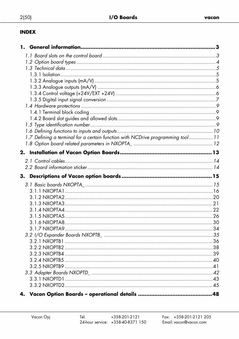
1.1 Board slots on the control board
Fig
The care foptioon thi
Vacon Oyj Tel. +358-201-2121 Fax: +358-201-2121 20524-hour service: +358-40-8371 150 Email: [email protected]
ure 1. Board slots on control board
ontrol board is situated inside the control unit of the Vacon NX frequency converter. Thereive board slots (labelled A to E) on the control board: The connectability of differentn boards to different slots depends greatly on the type of the board. For more informations, see Chapter 1.2. See also the descriptions of the options boards on pages 16 to 45.
A B C D E

4(50) I/O Boards vacon
Vacon Oyj Tel. +358-201-2121 Fax: +358-201-2121 20524-hour service: +358-40-8371 150 Email: [email protected]
Usually, when the frequency converter is delivered from the factory, the control unit includes atleast the standard compilation of two basic boards (I/O board and relay board) which arenormally installed in slots A and B. The I/O boards mounted at the factory are indicated in thetype code of the frequency converter. The three expander slots C, D and E are available fordifferent option boards i.e. I/O expander boards, fieldbus boards and adapter boards.
1.2 Option board types
The Vacon option boards are divided in four groups according to their characteristics: types A,B, C and D. Short descriptions of the types below:
NXOPTA_• Basic boards used for basic I/O; normally pre-installed at the factory• This board type uses slots A, B or C.
See pages 15 to 34 for a detailed presentation of the boards of this type. See also theprinciple diagram on the options boards and their equipment on page 48.
NXOPTB_• Option boards used for I/O expansion• Normally pluggable into slots B, C, D and E
See pages 35 to 41 for a detailed presentation of the boards of this type. See also theprinciple diagram on the options boards and their equipment on page 48.
NXOPTC_• Fieldbus boards (e.g. Profibus or Modbus)• These boards are connected to slots D and E.
See a separate manual on each individual Fieldbus Board. Ask factory or your nearestdistributor for more information.
NXOPTD_• Adapter boards• Boards with fiber optic adapters, e.g. System Bus Fiber Optic Adapter Board.• Connect the adapter boards to slots D and E.
See pages 42 to 45 for a detailed presentation of the boards of this type. See also theprinciple diagram on the options boards and their equipment on page 48.

vacon I/O Boards 5(50)
Vacon Oyj Tel. +358-201-2121 Fax: +358-201-2121 20524-hour service: +358-40-8371 150 Email: [email protected]
1.3 Technical data
The data in the table below applies to the inputs and outputs on all basic and expanderboards.
Safety (all boards) Comply with EN50178, C-UL and EN60204-1Inputs/outputs galvanically isolated; Isolation voltage rate 500V
Input/output type SpecificationAnalogue inputs (AI), voltage 0…±10V, Ri ≥ 200 kΩ, single-ended;
Resolution 10 bits/0.1%, accuracy ±1% of the full display(–10…+10V joystick control)
Analogue inputs (AI), current 0(4)…20mA, Ri = 250Ω, differentialResolution 10 bits/0.1%, accuracy ±1% of the full display
Digital inputs (DI), DC voltage controlled 24V: "0"≤10V, "1"≥18V, Ri > 5kΩDigital inputs (DI), AC voltage controlled Control voltage 42…240 VAC
"0"<33V, "1">35VAuxiliary voltage (output) (+24V) 24V (±15%), max 250mA (total summarized load from ext. +24V
outputs, max. 150 mA from one board.Auxiliary voltage (input) (ext. +24V) 24VDC (±10%, max. ripple voltage 100mV RMS), max. 1A.
In special applications where PLC type functions are included in thecontrol unit the input can be used as external auxiliary powersupply for control boards as well as I/O boards.
Reference voltage (output) (+10Vref) 10V – 0% – +2%, max. 10mAAnalogue output (AO), current (mA) 0(4)…20mA, RL<500Ω, resolution 10 bits/0.1%, accuracy ≤ ±2%Analogue output (AO), voltage (V) 0(2)…10V, RL ≥ 1kΩ, resolution 10 bits, accuracy ≤ ±2%Relay outputs (RO) Switching capacity 24VDC/8A
250VAC/8A125VDC/0.4A
Max. continuous load 2A rmsThermistor input (TI) Rtrip = 4.7kΩ (PTC type)Encoder control voltage (+5V/+15V/+24V) See NXOPTA4 and NXOPTA5 technical data on pp. 22Encoder connections (inputs, outputs) See NXOPTA4 and NXOPTA5 technical data on pp. 22
1.3.1 Isolation
The control connections are isolated from the mains potential and the I/O ground is connecteddirectly to the frame of the frequency converter. Digital inputs and relay outputs are isolatedfrom the I/O ground. For digital input arrangements, see Chapter Digital input signalconversions on page 7.
1.3.2 Analogue inputs (mA/V)
Analogue inputs of I/O boards can be used as either current inputs or voltage inputs (seedetailed description of each board). The signal type is selected with a jumper block on theboard. In case the voltage type input is used you still have to define the voltage range withanother jumper block. The factory default value for the analogue signal type is given in thedescription of the board. For detailed information, see the description of the board in question.
6(50) I/O Boards vacon
Vacon Oyj
1.3.3 Analogue outputs (mA/V)
In the same way as in the analogue inputs, the output signal type (current/voltage) can beselected with jumper except for some expander boards with analogue outputs used only withcurrent signals.
1.3.4 Control voltage (+24V/EXT +24V)
The control voltage output +24V/EXT+24V can be used in two ways. Typically, the +24Vcontrol voltage is wired to digital inputs through an external switch. The control voltage canalso be used to power-up external equipment, such as encoders and auxiliary relays.
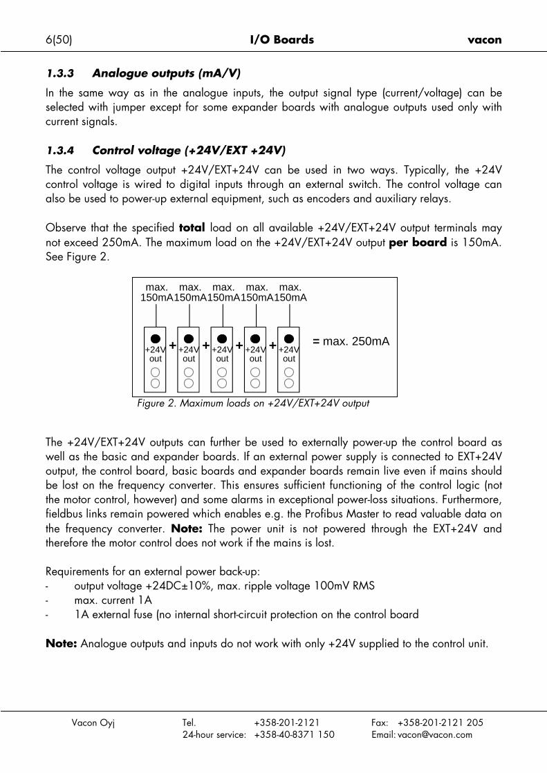
Observe that the specified total load on all available +24V/EXT+24V output terminals maynot exceed 250mA. The maximum load on the +24V/EXT+24V output per board is 150mA.See Figure 2.
The +24V/EXT+24well as the basic aoutput, the control be lost on the freqthe motor control, fieldbus links remathe frequency contherefore the motor
Requirements for a- output voltag- max. current- 1A external
Note: Analogue o
max.150mA
max.150mA
max.150mA
max.150mA
max.150mA
Tel. +358-201-2121 Fax: +358-201-2121 20524-hour service: +358-40-8371 150 Email: [email protected]
Figure 2. Maximum loads on +24V/EXT+24V output
V outputs can further be used to externally power-up the control board asnd expander boards. If an external power supply is connected to EXT+24Vboard, basic boards and expander boards remain live even if mains shoulduency converter. This ensures sufficient functioning of the control logic (nothowever) and some alarms in exceptional power-loss situations. Furthermore,in powered which enables e.g. the Profibus Master to read valuable data onverter. Note: The power unit is not powered through the EXT+24V and control does not work if the mains is lost.
n external power back-up:e +24DC±10%, max. ripple voltage 100mV RMS 1Afuse (no internal short-circuit protection on the control board
utputs and inputs do not work with only +24V supplied to the control unit.
+24Vout
+24Vout
+24Vout
+24Vout
+24Vout
+ + + + = max. 250mA

vacon I/O Boards 7(50)
Vacon Oyj Tel. +358-201-2121 Fax: +358-201-2121 20524-hour service: +358-40-8371 150 Email: [email protected]
If there is a +24V/EXT+24V output on the board it is short-circuit protected locally. Should oneof the +24V/EXT+24V outputs short-circuit, the others would remain powered because of thelocal protection.
1.3.5 Digital input signal conversion
The active signal level depends on which potential the common input CMA (and CMB ifavailable) is connected to. The alternatives are +24V or Ground (0V). See Figure 3, Figure 4and Figure 5.
The 24-volt control voltage and the ground for the digital inputs and the common input (CMA)can be either internal or external.
Some typical input signal conversion examples are shown below. If you use the internal +24Vfrom the frequency converter, the following arrangements are possible:
Figure 3. If CMA is connected to GND with inboardjumper the internal +24V is used and the CMAterminal need not be wired
If you use an external +24V the following arrangements are possible:
+24V/EXT+24V
DI1
DI2
DI3
GND
Jumper setting: = CMA connected to GND
8(50) I/O Boards vacon
Vacon Oyj
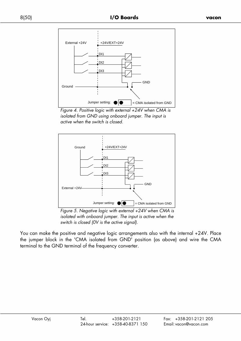
You can make the the jumper block terminal to the GN
Figure 4. Positive logic with external +24V when CMA isisolated from GND using onboard jumper. The input isactive when the switch is closed.
+24V/EXT+24V
DI1
DI2
DI3
GND
Jumper setting: = CMA isolated from GND
Ground
External +24V
Tel. +358-201-2121 Fax: +358-201-2121 20524-hour service: +358-40-8371 150 Email: [email protected]
Figure 5. Negative logic with external +24V when CMA isisolated with onboard jumper. The input is active when theswitch is closed (0V is the active signal).
positive and negative logic arrangements also with the internal +24V. Placein the 'CMA isolated from GND' position (as above) and wire the CMAD terminal of the frequency converter.
+24V/EXT+24V
DI1
DI2
DI3
GND
Jumper setting: = CMA isolated from GND
External +24V
Ground
vacon I/O Boards 9(50)
1.4 Hardware protections
1.4.1 Terminal block coding
In order to avoid incorrect connections of terminal blocks to boards, some terminal blocks aswell as related terminal connectors on the board are uniquely coded. For more information,see the description of the individual board.
1.4.2 Board slot guides and allowed slots
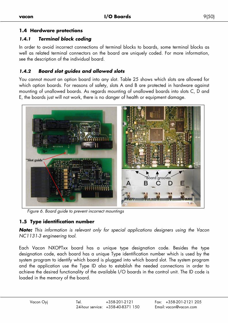
You cannot mount an option board into any slot. Table 25 shows which slots are allowed forwhich option boards. For reasons of safety, slots A and B are protected in hardware againstmounting of unallowed boards. As regards mounting of unallowed boards into slots C, D andE, the boards just will not work, there is no danger of health or equipment damage.
1.
NoNC
Eadesysanacloa
Vacon Oyj Tel. +358-201-2121 Fax: +358-201-2121 20524-hour service: +358-40-8371 150 Email: [email protected]
Figure 6. Board guide to prevent incorrect mountings
5 Type identification number
te: This information is relevant only for special applications designers using the Vacon1131-3 engineering tool.
ch Vacon NXOPTxx board has a unique type designation code. Besides the typesignation code, each board has a unique Type identification number which is used by thetem program to identify which board is plugged into which board slot. The system programd the application use the Type ID also to establish the needed connections in order tohieve the desired functionality of the available I/O boards in the control unit. The ID code isded in the memory of the board.
"Slot guide"
Board grooves
10(50) I/O Boards vacon
Vacon Oyj Tel. +358-201-2121 Fax: +358-201-2121 20524-hour service: +358-40-8371 150 Email: [email protected]
READY
I/Oterm
DigOUT:B.1AI Ref Faul/Warn
1.6 Defining functions to inputs and outputs
How to connect functions and the available I/O depends on the application you use. TheVacon All in One Application Package includes seven applications: Basic Application,Standard Application, PID Control Application, Multi-Step Speed Control Application,Local/Remote Control Application, Pump and Fan Control Application with Autochange andMultipurpose Control Application (see Application Manuals). All but two applications of theseuse the conventional Vacon method to connect functions and the I/O. In the Function toTerminal Programming Method (FTT), you have a fixed input or output that you define a certainfunction for. The mentioned two applications, Pump and Fan Control and MultipurposeControl Application, however, use the Terminal to Function Programming Method (TTF) inwhich the programming process is carried out the other way round: Functions appear asparameters which the operator defines a certain input/output for.
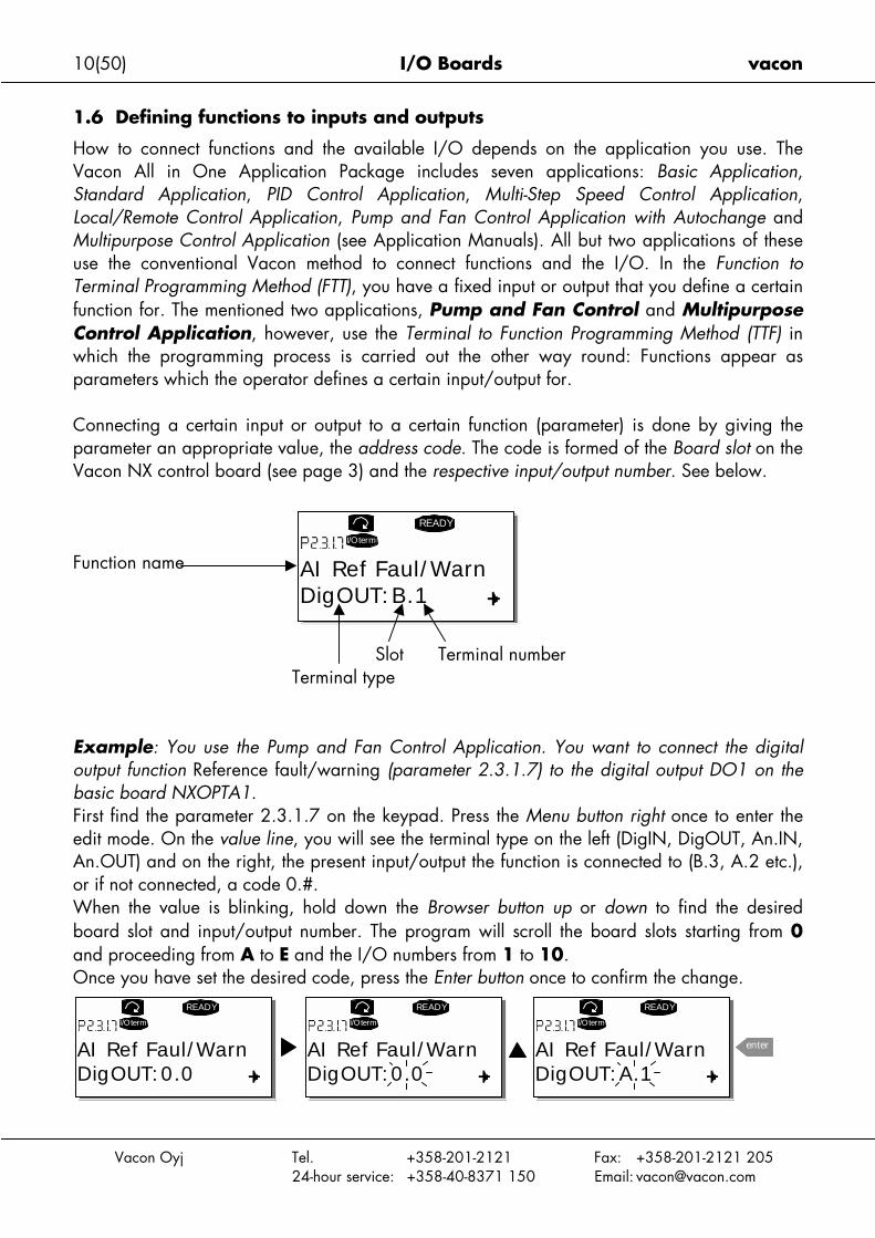
Connecting a certain input or output to a certain function (parameter) is done by giving theparameter an appropriate value, the address code. The code is formed of the Board slot on theVacon NX control board (see page 3) and the respective input/output number. See below.
Function name
Slot Terminal numberTerminal type
Example: You use the Pump and Fan Control Application. You want to connect the digitaloutput function Reference fault/warning (parameter 2.3.1.7) to the digital output DO1 on thebasic board NXOPTA1.First find the parameter 2.3.1.7 on the keypad. Press the Menu button right once to enter theedit mode. On the value line, you will see the terminal type on the left (DigIN, DigOUT, An.IN,An.OUT) and on the right, the present input/output the function is connected to (B.3, A.2 etc.),or if not connected, a code 0.#.When the value is blinking, hold down the Browser button up or down to find the desiredboard slot and input/output number. The program will scroll the board slots starting from 0and proceeding from A to E and the I/O numbers from 1 to 10.Once you have set the desired code, press the Enter button once to confirm the change.
READY
I/Oterm
DigOUT:0.0
READY
I/Oterm
DigOUT:0.0
READY
I/Oterm
DigOUT:A.1
enterAI Ref Faul/Warn AI Ref Faul/Warn AI Ref Faul/Warn

vacon I/O Boards 11(50)
Vacon Oyj Tel. +358-201-2121 Fax: +358-201-2121 20524-hour service: +358-40-8371 150 Email: [email protected]
1.7 Defining a terminal for a certain function with NCDrive programming tool
If you use the NCDrive Programming Tool for parametrizing you will have to establish theconnection between the function and input/output in the same way as with the control panel.Just pick the address code from the drop-down menu in the Value column (see Figure 7 below).
Figure 7. Screenshot of NCDrive programming tool; Entering the address code
!WARNING
Be ABSOLUTELY sure not to connect two functions toone and same output in order to avoid functionoverruns and to ensure flawless operation.
Note: The inputs, unlike the outputs, cannot be changed in RUN state.
12(50) I/O Boards vacon
Vacon Oyj Tel. +358-201-2121 Fax: +358-201-2121 20524-hour service: +358-40-8371 150 Email: [email protected]
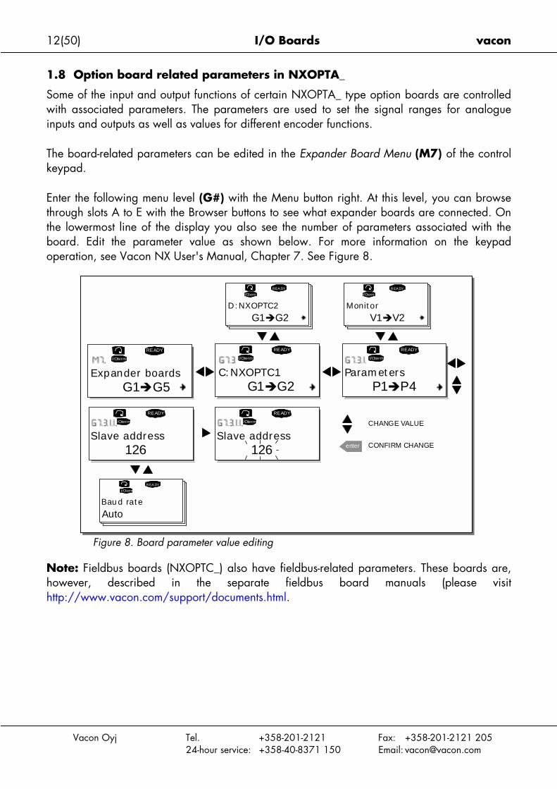
1.8 Option board related parameters in NXOPTA_
Some of the input and output functions of certain NXOPTA_ type option boards are controlledwith associated parameters. The parameters are used to set the signal ranges for analogueinputs and outputs as well as values for different encoder functions.
The board-related parameters can be edited in the Expander Board Menu (M7) of the controlkeypad.
Enter the following menu level (G#) with the Menu button right. At this level, you can browsethrough slots A to E with the Browser buttons to see what expander boards are connected. Onthe lowermost line of the display you also see the number of parameters associated with theboard. Edit the parameter value as shown below. For more information on the keypadoperation, see Vacon NX User's Manual, Chapter 7. See Figure 8.
Figure 8. Board parameter value editing
Note: Fieldbus boards (NXOPTC_) also have fieldbus-related parameters. These boards are,however, described in the separate fieldbus board manuals (please visithttp://www.vacon.com/support/documents.html.
G1!G5
READY
I/Oterm
C:NXOPTC1
READY
I/Oterm
G1!G2
READY
I/Oterm
READY
I/Oterm
enter
P1!P4
D:NXOPTC2
REA DY
I/Oterm
G1!G2
REA DY
I/Oterm
V1!V2
READY
I/Oterm
REA DY
I/Oterm
Expander boards Parameters
Slave address126
CHANGE VALUE
CONFIRM CHANGESlave address
126
Baud rate
Auto
Monitor
vacon I/O Boards 13(50)
Vacon Oyj Tel. +358-201-2121 Fax: +358-201-2121 20524-hour service: +358-40-8371 150 Email: [email protected]
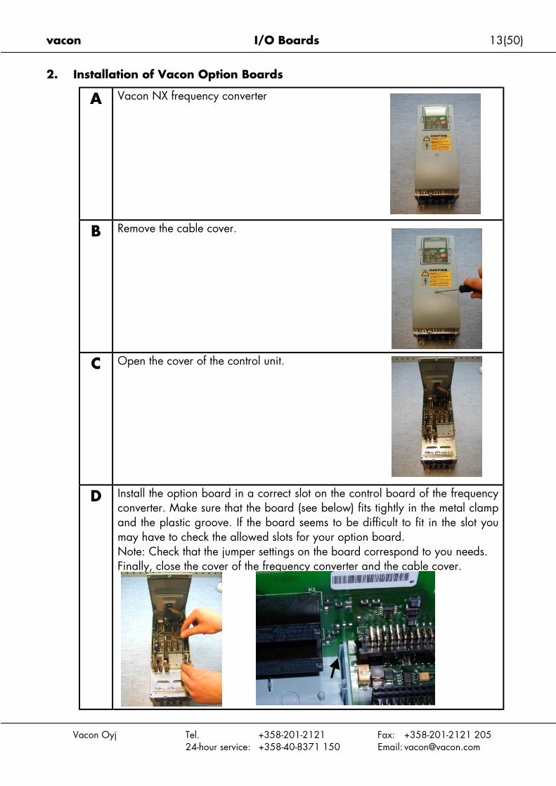
2. Installation of Vacon Option Boards
A Vacon NX frequency converter
B Remove the cable cover.
C Open the cover of the control unit.
D Install the option board in a correct slot on the control board of the frequencyconverter. Make sure that the board (see below) fits tightly in the metal clampand the plastic groove. If the board seems to be difficult to fit in the slot youmay have to check the allowed slots for your option board.Note: Check that the jumper settings on the board correspond to you needs.Finally, close the cover of the frequency converter and the cable cover.
14(50) I/O Boards vacon
Vacon Oyj Tel. +358-201-2121 Fax: +358-201-2121 20524-hour service: +358-40-8371 150 Email: [email protected]
2.1 Control cables
The control cables used shall be at least 0.5mm2 screened multicore cables. The maximumterminal wire size is 2.5mm2 for the relay terminals and 1.5 mm2 for other terminals.
Find the tightening torques of the option board terminals in Table below.
Tightening torqueTerminalscrew Nm lb-in.
Relay andthermistor terminals
(screw M3)0.5 4.5
Other terminals(screw M2.6)
0.4 3.5
Table 1. Tightening torques of terminals
Cable type Level H Level C*Control cable 4 4Table 2. Cable types required to meet standards.
Level H = EN 61800-3, 1st environmentEN 50081-2
Level C = EN 50081-1*Also requires an external filter between the frequency converter andthe mains
4 = Screened cable equipped with compact low-impedance shield (NNCABLES /Jamak, SAB/ÖZCuY-O orsimilar).
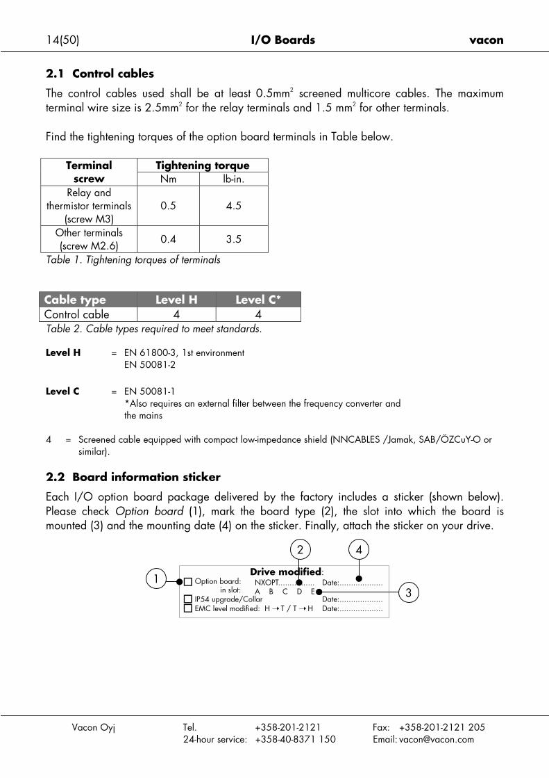
2.2 Board information sticker
Each I/O option board package delivered by the factory includes a sticker (shown below).Please check Option board (1), mark the board type (2), the slot into which the board ismounted (3) and the mounting date (4) on the sticker. Finally, attach the sticker on your drive.
Drive modified:Option board: NXOPT................
IP54 upgrade/Collarin slot:
Date:...................
A B C D E
EMC level modified: H T / T HDate:...................
Date:...................3
1
2 4
vacon I/O Boards 15(50)
Vacon Oyj Tel. +358-201-2121 Fax: +358-201-2121 20524-hour service: +358-40-8371 150 Email: [email protected]
3. Descriptions of Vacon option boards
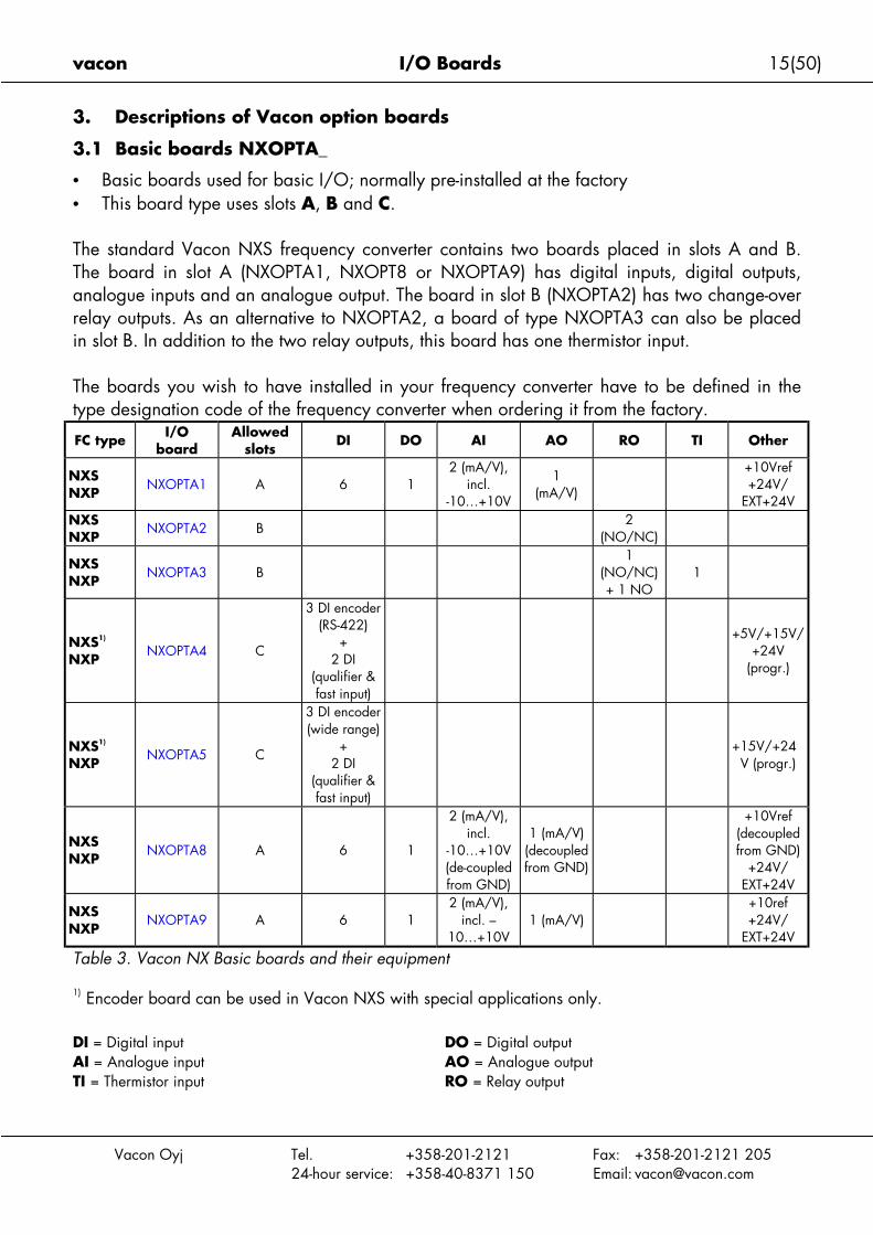
3.1 Basic boards NXOPTA_
• Basic boards used for basic I/O; normally pre-installed at the factory• This board type uses slots A, B and C.
The standard Vacon NXS frequency converter contains two boards placed in slots A and B.The board in slot A (NXOPTA1, NXOPT8 or NXOPTA9) has digital inputs, digital outputs,analogue inputs and an analogue output. The board in slot B (NXOPTA2) has two change-overrelay outputs. As an alternative to NXOPTA2, a board of type NXOPTA3 can also be placedin slot B. In addition to the two relay outputs, this board has one thermistor input.
The boards you wish to have installed in your frequency converter have to be defined in thetype designation code of the frequency converter when ordering it from the factory.
FC type I/Oboard
Allowedslots
DI DO AI AO RO TI Other
NXSNXP
NXOPTA1 A 6 12 (mA/V),
incl.-10…+10V
1(mA/V)
+10Vref+24V/
EXT+24VNXSNXP
NXOPTA2 B2
(NO/NC)
NXSNXP
NXOPTA3 B1
(NO/NC)+ 1 NO
1
NXS1)
NXPNXOPTA4 C
3 DI encoder(RS-422)
+2 DI
(qualifier &fast input)
+5V/+15V/+24V
(progr.)
NXS1)
NXPNXOPTA5 C
3 DI encoder(wide range)
+2 DI
(qualifier &fast input)
+15V/+24V (progr.)
NXSNXP
NXOPTA8 A 6 1
2 (mA/V),incl.
-10…+10V(de-coupledfrom GND)
1 (mA/V)(decoupledfrom GND)
+10Vref(decoupledfrom GND)
+24V/EXT+24V
NXSNXP
NXOPTA9 A 6 12 (mA/V),
incl. –10…+10V
1 (mA/V)+10ref+24V/
EXT+24V
Table 3. Vacon NX Basic boards and their equipment
1) Encoder board can be used in Vacon NXS with special applications only.
DI = Digital input DO = Digital outputAI = Analogue input AO = Analogue outputTI = Thermistor input RO = Relay output
16(50) I/O Boards vacon
NX
OPTA
1
3.1.1 NXOPTA1
D
A
T
T
J
B
Vacon Oyj Tel. +358-201-2121 Fax: +358-201-2121 20524-hour service: +358-40-8371 150 Email: [email protected]
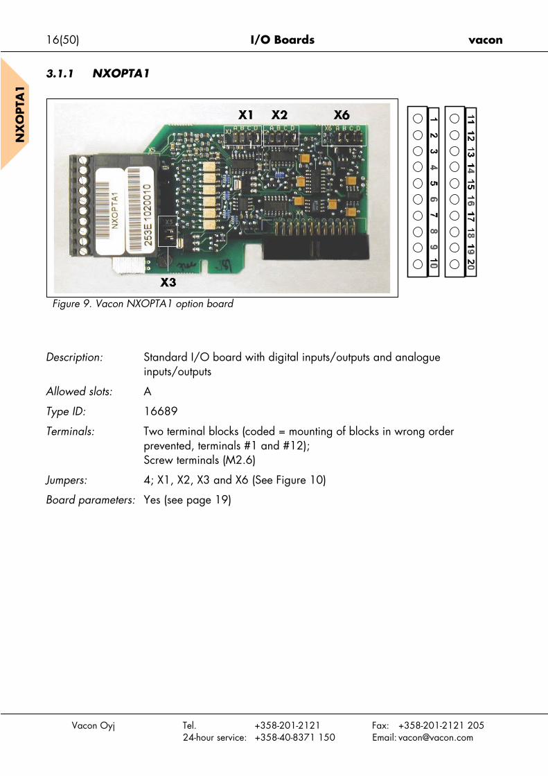
Figure 9. Vacon NXOPTA1 option board
escription: Standard I/O board with digital inputs/outputs and analogueinputs/outputs
llowed slots: A
ype ID: 16689
erminals: Two terminal blocks (coded = mounting of blocks in wrong orderprevented, terminals #1 and #12);Screw terminals (M2.6)
umpers: 4; X1, X2, X3 and X6 (See Figure 10)
oard parameters: Yes (see page 19)

vacon I/O Boards 17(50)
Vacon Oyj Tel. +358-201-2121 Fax: +358-201-2121 20524-hour service: +358-40-8371 150 Email: [email protected]
NX
OPTA
1
I/O terminals on NXOPTA1 (coded terminals painted black)
Terminal Parameter referenceon keypad and NCDrive
Technical information
1 +10 Vref Reference output +10V; Maximum current 10 mA2 AI1+ An.IN:A.1 Selection V or mA with jumper block X1 (see page 18):
Default: 0– +10V (Ri = 200 kΩ)(-10V…..+10V Joy-stick control, selected with a jumper)0– 20mA (Ri = 250 Ω)
Resolution 0.1%; Accuracy ±1%3 AI1– Differential input if not connected to ground;
Allows ±20V differential mode voltage to GND4 AI2+ An.IN:A.2 Selection V or mA with jumper block X2 (see page 18):
Default: 0– 20mA (Ri = 250 Ω)0– +10V (Ri = 200 kΩ)(-10V…..+10V Joy-stick control, selected with a jumper)
Resolution: 0.1%; Accuracy ±1%5 AI2– Differential input if not connected to ground;
Allows ±20V differential mode voltage to GND6 24 Vout
(bidirectional)24V auxiliary voltage output. Short-circuit protected.±15%, maximum current 150 mA, see 1.3.4+24Vdc external supply may be connected.Galvanically connected to terminal #12.
7 GND Ground for reference and controlsGalvanically connected to terminals #13,19.
8 DIN1 DigIN:A.1 Digital input 1 (Common CMA); Ri = min. 5kΩ9 DIN2 DigIN:A.2 Digital input 2 (Common CMA); Ri = min. 5kΩ
10 DIN3 DigIN:A.3 Digital input 3 (Common CMA); Ri = min. 5kΩ11 CMA Digital input common B for DIN1, DIN2 and DIN3.
Connection by default to GND.Selection with jumper block X3 (see page 18):
12 24 Vout(bidirectional)
Same as terminal #6Galvanically connected to terminal #6.
13 GND Same as terminal #7Galvanically connected to terminals #7 and 19
14 DIN4 DigIN:A.4 Digital input 4 (Common CMB); Ri = min. 5kΩ15 DIN5 DigIN:A.5 Digital input 5 (Common CMB); Ri = min. 5kΩ16 DIN6 DigIN:A.6 Digital input 6 (Common CMB); Ri = min. 5kΩ17 CMB Digital input common A for DIN4, DIN5 and DIN6.
Connection by default to GND.Selection with jumper block X3 (see page 18):
18 AO1+ AnOUT:A.119 AO1–
Analogue outputOutput signal range:Current 0(4)–20mA, RL max 400Ω orVoltage 0—10V, RL >1kΩSelection with jumper block X6 (see page 18):Resolution: 0.1% (10 bits); Accuracy ±2%
20 DO1 DigOUT:A.1 Open collector outputMaximum Uin = 48VDCMaximum current = 50 mA
Table 4. NXOPTA1 I/O terminals

18(50) I/O Boards vacon
Vacon O
NX
OPTA
1 Jumper selections
There are four jumper blocks on the NXOPTA1 board. The factory defaults and other availablejumper selections are presented below.
Jumper block X1:AI1 mode
Jumper block X2:AI2 mode
yj Tel. +358-201-2121 Fax: +358-201-2121 20524-hour service: +358-40-8371 150 Email: [email protected]
Figure 10. Jumper block selection on NXOPTA1
A B C D
A B C D
A B C D
A B C D
A B C D
A B C D
A B C D
A B C D
A B C D
A B C D
AI1 mode: Voltage input; 0...10V
AI1 mode: Voltage input; 0...10V (differential)
AI1 mode: Voltage input; -10...10V
AI2 mode: 0...20mA; Current input
AI2 mode: Voltage input; 0...10V
AI2 mode: Voltage input; 0...10V (differential)
AI2 mode: Voltage input; -10...10V
Jumper block X3:CMA and CMB grounding
CMB connected to GNDCMA connected to GND
CMB isolated from GNDCMA isolated from GND
CMB and CMAinternally connected together,isolated from GND
= Factory default
Jumper block X6:AO1 mode
AO1 mode: 0...20mA; Current output
AO1 mode: Voltage output; 0...10V
AI1 mode: 0...20mA; Current input

vacon I/O Boards 19(50)
Vacon Oyj Tel. +358-201-2121 Fax: +358-201-2121 20524-hour service: +358-40-8371 150 Email: [email protected]
NX
OPTA
1
NXOPTA1 parameters
Number Parameter Min Max Default Note
1 AI1 mode 1 5 3
1 = 0...20mA2 = 4...20mA3 = 0...10V4 = 2...10V5 = -10...+10V
2 AI2 mode 1 5 1
1 = 0...20mA2 = 4...20mA3 = 0...10V4 = 2...10V5 = -10...+10V
3 AO1 mode 1 4 1
1 = 0...20mA2 = 4...20mA3 = 0...10V4 = 2...10V
Table 5. NXOPTA1 board-related parameters

20(50) I/O Boards vacon
Vacon Oyj Tel. +358-201-2121 Fax: +358-201-2121 20524-hour service: +358-40-8371 150 Email: [email protected]
NX
OPTA
2
3.1.2 NXOPTA2
Description: Standard Vacon NX frequency converter relay board with two relayoutputs
Allowed slots: B
Type ID: 16690
Terminals: Two terminal blocks; Screw terminals (M3); No coding
Jumpers: None
Board parameters: None
I/O terminals on NXOPTA2
Terminal Parameter referenceon keypad and
NCDrive
Technical information
212223
RO1/normal closedRO1/commonRO1/normal open DigOUT:B.1
Relay output 1 (NO/NC)Switching capacity 24VDC/8A
250VAC/8A125VDC/0.4A
242526
RO2/normal closedRO2/commonRO2/normal open DigOUT:B.2
Relay output 2 (NO/NC)Switching capacity 24VDC/8A
250VAC/8A125VDC/0.4A
Table 6. NXOPTA2 I/O terminals
vacon I/O Boards 21(50)
Vacon Oyj Tel. +358-201-2121 Fax: +358-201-2121 20524-hour service: +358-40-8371 150 Email: [email protected]
NX
OPTA
3
3.1.3 NXOPTA3
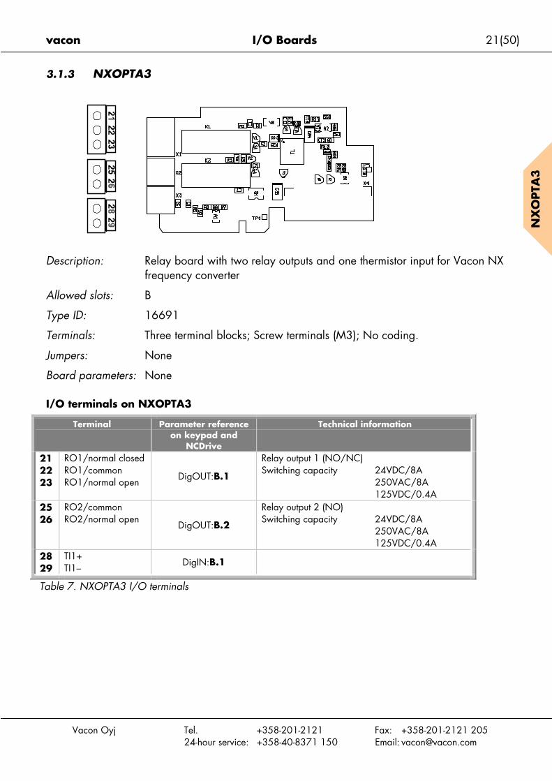
Description: Relay board with two relay outputs and one thermistor input for Vacon NXfrequency converter
Allowed slots: B
Type ID: 16691
Terminals: Three terminal blocks; Screw terminals (M3); No coding.
Jumpers: None
Board parameters: None
I/O terminals on NXOPTA3
Terminal Parameter referenceon keypad and
NCDrive
Technical information
212223
RO1/normal closedRO1/commonRO1/normal open DigOUT:B.1
Relay output 1 (NO/NC)Switching capacity 24VDC/8A
250VAC/8A125VDC/0.4A
2526
RO2/commonRO2/normal open
DigOUT:B.2
Relay output 2 (NO)Switching capacity 24VDC/8A
250VAC/8A125VDC/0.4A
2829
TI1+TI1– DigIN:B.1
Table 7. NXOPTA3 I/O terminals

22(50) I/O Boards vacon
Vacon Oyj Tel. +358-201-2121 Fax: +358-201-2121 20524-hour service: +358-40-8371 150 Email: [email protected]
NX
OPTA
4
3.1.4 NXOPTA4
Description: Encoder board for Vacon NXP. Encoder input board withprogrammable control voltage for an encoder
The encoder board NXOPTA4 is for TTL type encoders (TTL, TTL(R))providing input signal levels that meet the RS_422 interface standard.Encoder inputs A, B and Z are not galvanically isolated. The NXOPTA4board includes, too, the qualifier input ENC1Q (meant to trace the Z-pulsein certain situations) and a special/fast digital input DIC4 (used to tracevery short pulses). These two inputs are used in special applications.
The TTL type encoders do not have an internal regulator and use thereforea supply voltage of +5V±5% whereas the TTL(R) type encoders have aninternal regulator and the supply voltage can be e.g. +15V±10%(depending on the encoder manufacturer).
Allowed slots: C
Type ID: 16692
Terminals: One terminal block; Screw terminals (M2.6); Coding in terminal #3.
Jumpers: 1; X4 (see page 23)
Board parameters: Yes (see page 25)
Jumper X4
vacon I/O Boards 23(50)
Vacon Oyj Tel. +358-201-2121 Fax: +358-201-2121 20524-hour service: +358-40-8371 150 Email: [email protected]
NX
OPTA
4
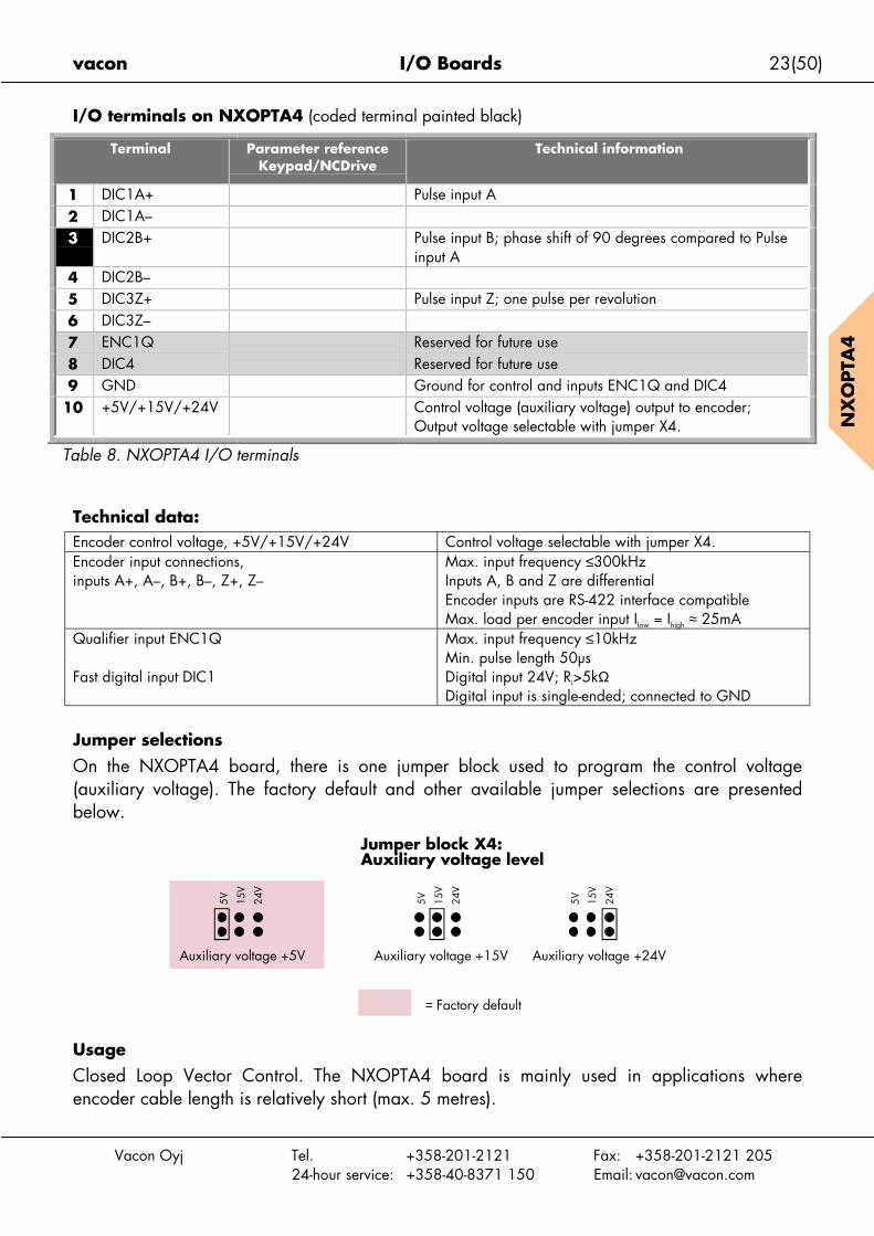
I/O terminals on NXOPTA4 (coded terminal painted black)
Terminal Parameter referenceKeypad/NCDrive
Technical information
1 DIC1A+ Pulse input A2 DIC1A–3 DIC2B+ Pulse input B; phase shift of 90 degrees compared to Pulse
input A4 DIC2B–5 DIC3Z+ Pulse input Z; one pulse per revolution6 DIC3Z–7 ENC1Q Reserved for future use8 DIC4 Reserved for future use9 GND Ground for control and inputs ENC1Q and DIC4
10 +5V/+15V/+24V Control voltage (auxiliary voltage) output to encoder;Output voltage selectable with jumper X4.
Table 8. NXOPTA4 I/O terminals
Technical data:Encoder control voltage, +5V/+15V/+24V Control voltage selectable with jumper X4.Encoder input connections,inputs A+, A–, B+, B–, Z+, Z–
Max. input frequency ≤300kHzInputs A, B and Z are differentialEncoder inputs are RS-422 interface compatibleMax. load per encoder input Ilow = Ihigh ≈ 25mA
Qualifier input ENC1Q
Fast digital input DIC1
Max. input frequency ≤10kHzMin. pulse length 50µsDigital input 24V; Ri>5kΩDigital input is single-ended; connected to GND
Jumper selections
On the NXOPTA4 board, there is one jumper block used to program the control voltage(auxiliary voltage). The factory default and other available jumper selections are presentedbelow.
UsageClosed Loop Vector Control. The NXOPTA4 board is mainly used in applications whereencoder cable length is relatively short (max. 5 metres).
5V 15V
24V
= Factory default
5V 15V
24V
5V 15V
24V
Jumper block X4:Auxiliary voltage level
Auxiliary voltage +15V Auxiliary voltage +24VAuxiliary voltage +5V

24(50) I/O Boards vacon
NX
OPTA
4
Encoder connection – Differential
Figure 11. RS-422 type encoder connection using differential inputs
Note:The encoder pulses are handled by Vacon software as presented below:
GND
Encoder
5V/15V/24V from the NXOPTA4-board or from external supply*
NXOPTA4-board
.
.10 +5/+15V/+24V9 GND
1 DIC1A+2 DIC1A-
3 DIC2B+4 DIC2B-5 DIC3Z+6 DIC3Z-7 ENC1Q8 DIC1..
+5V**
*If external supply is used rememberto connect the ground of externalsupply to terminal #9 of the NXOPTA4and to the encoder ground**+5V/+15V/+24V
OUTPUT SIGNALS
Vacon Oyj Tel. +358-201-2121 Fax: +358-201-2121 20524-hour service: +358-40-8371 150 Email: [email protected]
A
Clockwise, seen from shaft
B
360º el.1 period 90º el. (channel separation)
vacon I/O Boards 25(50)
Vacon Oyj Tel. +358-201-2121 Fax: +358-201-2121 20524-hour service: +358-40-8371 150 Email: [email protected]
NX
OPTA
4
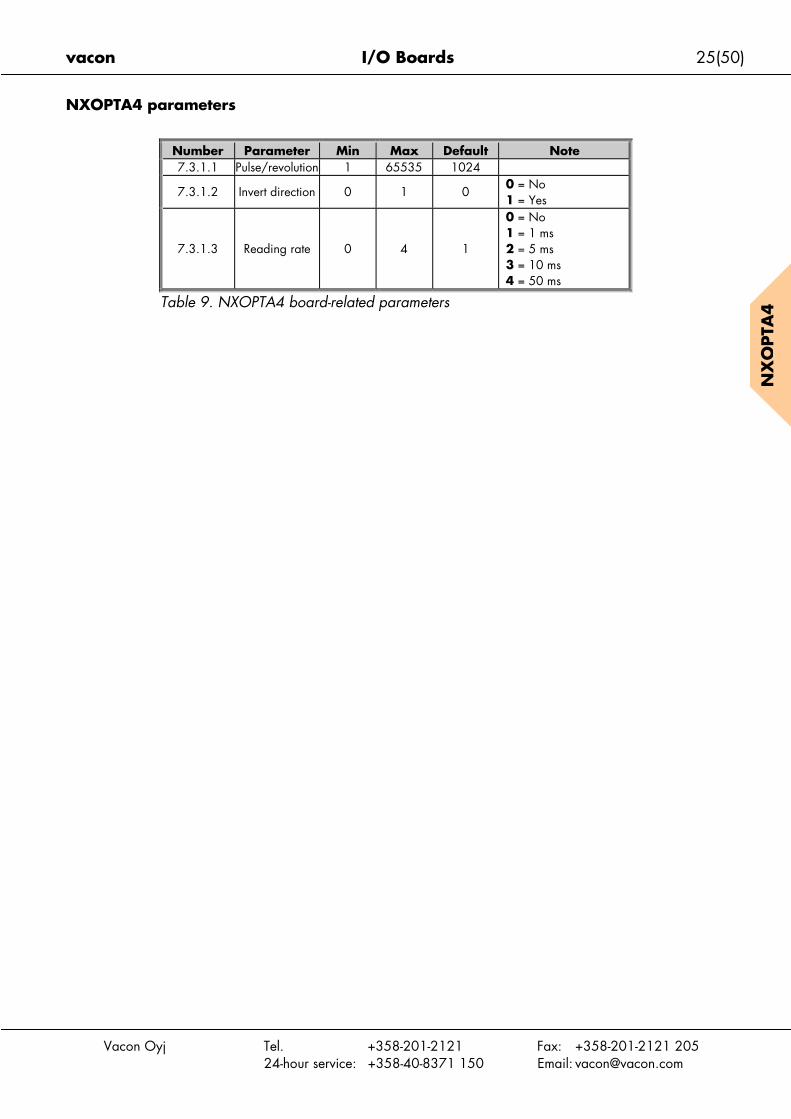
NXOPTA4 parameters
Number Parameter Min Max Default Note7.3.1.1 Pulse/revolution 1 65535 1024
7.3.1.2 Invert direction 0 1 00 = No1 = Yes
7.3.1.3 Reading rate 0 4 1
0 = No1 = 1 ms2 = 5 ms3 = 10 ms4 = 50 ms
Table 9. NXOPTA4 board-related parameters

26(50) I/O Boards vacon
Vacon Oyj Tel. +358-201-2121 Fax: +358-201-2121 20524-hour service: +358-40-8371 150 Email: [email protected]
NX
OPTA
5
3.1.5 NXOPTA5
Description: Encoder board for Vacon NXP. Encoder input board withprogrammable control voltage for an encoder.
The NXOPTA5 board is designed for HTL (High voltage Transistor Logic)type encoders (voltage output type push-pull HTL, open collector outputtype HTL) which provide input signal levels dependent on the supplyvoltage of the encoder. The encoder inputs A, B and Z are galvanicallyisolated. The NXOPTA5 board includes, too, the qualifier input ENC1Q(meant to trace the Z-pulse in certain situations) and a fast digital inputDIC4 (used to trace very short pulses). These two inputs are used in specialapplications.
The NXOPTA5 is similar to the NXOPTA4 in connections but the encoderinputs A, B and Z have different signal levels (voltage level). The inputlevels for A, B and Z of the NXOPTA4 are compatible with RS-422 whilethose of the NXOPTA5 are more general wide range inputs. InputsENC1Q and DIC4 are identical in both boards.
Allowed slots: C
Type ID: 16693
Terminals: One terminal block; Screw terminals (M2.6); Coding in terminal #3.
Jumpers: 1; X4 (see page 27)
Board parameters: Yes (see page 25)
Jumper X4
vacon I/O Boards 27(50)
Vacon Oyj Tel. +358-201-2121 Fax: +358-201-2121 20524-hour service: +358-40-8371 150 Email: [email protected]
NX
OPTA
5
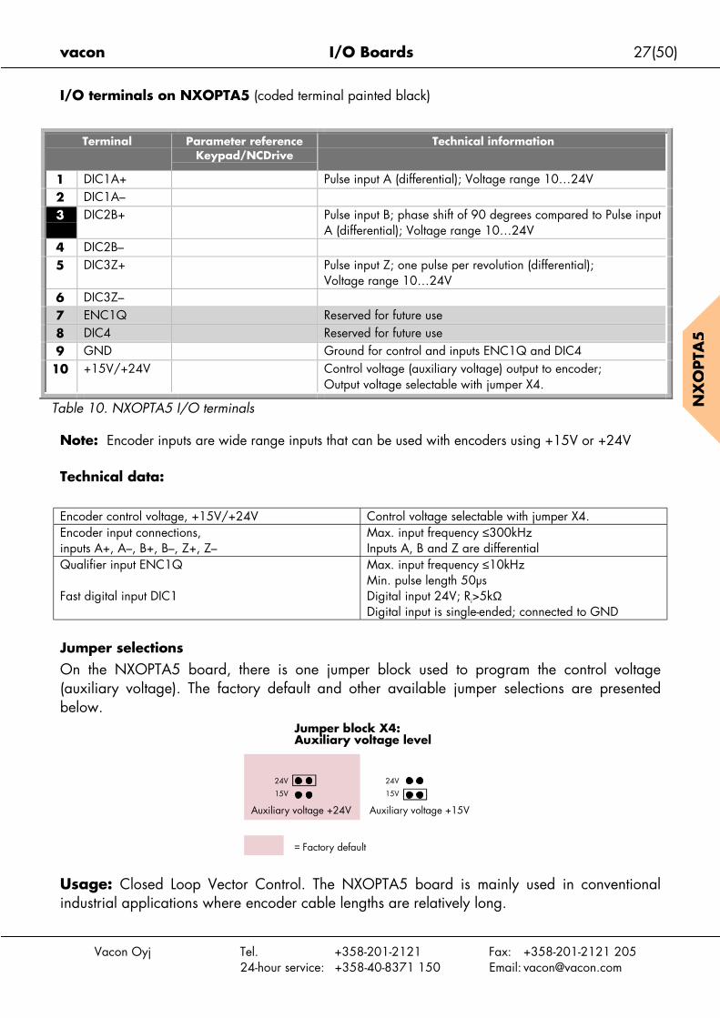
I/O terminals on NXOPTA5 (coded terminal painted black)
Terminal Parameter referenceKeypad/NCDrive
Technical information
1 DIC1A+ Pulse input A (differential); Voltage range 10…24V2 DIC1A–3 DIC2B+ Pulse input B; phase shift of 90 degrees compared to Pulse input
A (differential); Voltage range 10…24V4 DIC2B–5 DIC3Z+ Pulse input Z; one pulse per revolution (differential);
Voltage range 10…24V6 DIC3Z–7 ENC1Q Reserved for future use8 DIC4 Reserved for future use9 GND Ground for control and inputs ENC1Q and DIC4
10 +15V/+24V Control voltage (auxiliary voltage) output to encoder;Output voltage selectable with jumper X4.
Table 10. NXOPTA5 I/O terminals
Note: Encoder inputs are wide range inputs that can be used with encoders using +15V or +24V
Technical data:
Encoder control voltage, +15V/+24V Control voltage selectable with jumper X4.Encoder input connections,inputs A+, A–, B+, B–, Z+, Z–
Max. input frequency ≤300kHzInputs A, B and Z are differential
Qualifier input ENC1Q
Fast digital input DIC1
Max. input frequency ≤10kHzMin. pulse length 50µsDigital input 24V; Ri>5kΩDigital input is single-ended; connected to GND
Jumper selections
On the NXOPTA5 board, there is one jumper block used to program the control voltage(auxiliary voltage). The factory default and other available jumper selections are presentedbelow.
Usage: Closed Loop Vector Control. The NXOPTA5 board is mainly used in conventionalindustrial applications where encoder cable lengths are relatively long.
= Factory default
24V
15V
24V
15V
Jumper block X4:Auxiliary voltage level
Auxiliary voltage +24V Auxiliary voltage +15V
28(50) I/O Boards vacon
NX
OPTA
5
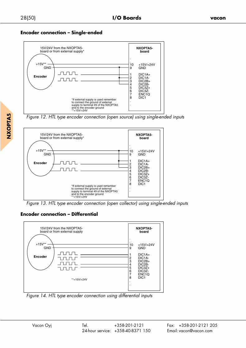
Encoder connection – Single-ended
En
Figure 12. HTL type encoder connection (open source) using single-ended inputs
GND
Encoder
15V/24V from the NXOPTA5-board or from external supply*
NXOPTA5-board
.
.10 +15V/+24V9 GND
1 DIC1A+2 DIC1A-3 DIC2B+4 DIC2B-5 DIC3Z+6 DIC3Z-7 ENC1Q8 DIC1..
+15V**
*If external supply is used rememberto connect the ground of externalsupply to terminal #9 of the NXOPTA5and to the encoder ground**+15V/+24V
Vacon Oyj Tel. +358-201-2121 Fax: +358-201-2121 20524-hour service: +358-40-8371 150 Email: [email protected]
Figure 13. HTL type encoder connection (open collector) using single-ended inputs
coder connection – Differential
Figure 14. HTL type encoder connection using differential inputs
GND
Encoder
+15V**
15V/24V from the NXOPTA5-board or from external supply*
NXOPTA5-board
.
.10 +15V/+24V9 GND
1 DIC1A+2 DIC1A-3 DIC2B+4 DIC2B-5 DIC3Z+6 DIC3Z-7 ENC1Q8 DIC1..
*If external supply is used rememberto connect the ground of externalsupply to terminal #9 of the NXOPTA5and to the encoder ground**+15V/+24V
GND+15V**
15V/24V from the NXOPTA5-board or from external supply
NXOPTA5-board
.
.10 +15V/+24V9 GND
1 DIC1A+2 DIC1A-3 DIC2B+4 DIC2B-5 DIC3Z+6 DIC3Z-7 ENC1Q8 DIC1..
**+15V/+24V
Encoder

vacon I/O Boards 29(50)
Vacon Oyj Tel. +358-201-2121 Fax: +358-201-2121 20524-hour service: +358-40-8371 150 Email: [email protected]
NX
OPTA
5
NXOPTA5 parametersSee page 25.

30(50) I/O Boards vacon
Vacon Oyj Tel. +358-201-2121 Fax: +358-201-2121 20524-hour service: +358-40-8371 150 Email: [email protected]
NX
OPTA
8
3.1.6 NXOPTA8
Description: Vacon NX basic I/O board similar to NXOPTA1 except that the analogueinputs and output are galvanically decoupled.
Allowed slots: A
Type ID: 16696
Terminals: Two terminal blocks; Screw terminals (M2.6); Coding in terminals #1 and#12.
Jumpers: 4; X1, X2, X3 and X6 (see page 32)
Board parameters: Yes (see page 33)
Jumper X1Jumper X2
Jumper X6
Jumper X3
vacon I/O Boards 31(50)
Vacon Oyj Tel. +358-201-2121 Fax: +358-201-2121 20524-hour service: +358-40-8371 150 Email: [email protected]
NX
OPTA
8
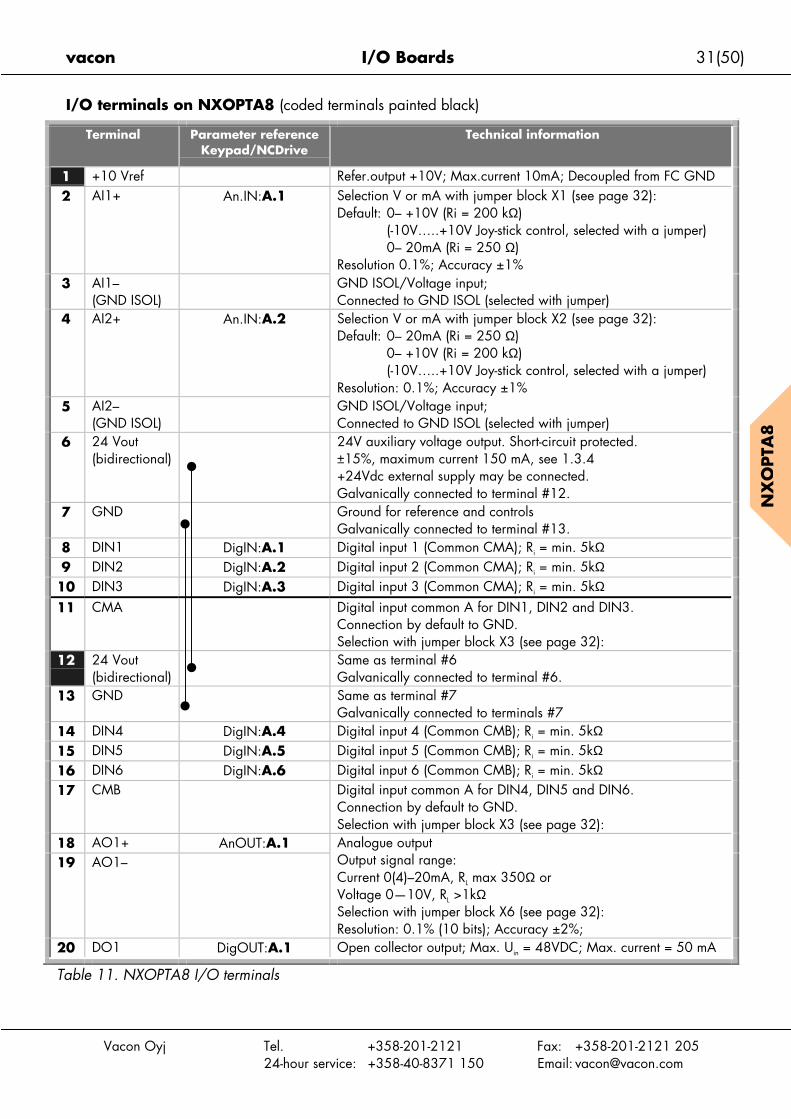
I/O terminals on NXOPTA8 (coded terminals painted black)
Terminal Parameter referenceKeypad/NCDrive
Technical information
1 +10 Vref Refer.output +10V; Max.current 10mA; Decoupled from FC GND2 AI1+ An.IN:A.1 Selection V or mA with jumper block X1 (see page 32):
Default: 0– +10V (Ri = 200 kΩ)(-10V…..+10V Joy-stick control, selected with a jumper)0– 20mA (Ri = 250 Ω)
Resolution 0.1%; Accuracy ±1%3 AI1–
(GND ISOL)GND ISOL/Voltage input;Connected to GND ISOL (selected with jumper)
4 AI2+ An.IN:A.2 Selection V or mA with jumper block X2 (see page 32):Default: 0– 20mA (Ri = 250 Ω)
0– +10V (Ri = 200 kΩ)(-10V…..+10V Joy-stick control, selected with a jumper)
Resolution: 0.1%; Accuracy ±1%5 AI2–
(GND ISOL)GND ISOL/Voltage input;Connected to GND ISOL (selected with jumper)
6 24 Vout(bidirectional)
24V auxiliary voltage output. Short-circuit protected.±15%, maximum current 150 mA, see 1.3.4+24Vdc external supply may be connected.Galvanically connected to terminal #12.
7 GND Ground for reference and controlsGalvanically connected to terminal #13.
8 DIN1 DigIN:A.1 Digital input 1 (Common CMA); Ri = min. 5kΩ9 DIN2 DigIN:A.2 Digital input 2 (Common CMA); Ri = min. 5kΩ
10 DIN3 DigIN:A.3 Digital input 3 (Common CMA); Ri = min. 5kΩ11 CMA Digital input common A for DIN1, DIN2 and DIN3.
Connection by default to GND.Selection with jumper block X3 (see page 32):
12 24 Vout(bidirectional)
Same as terminal #6Galvanically connected to terminal #6.
13 GND Same as terminal #7Galvanically connected to terminals #7
14 DIN4 DigIN:A.4 Digital input 4 (Common CMB); Ri = min. 5kΩ15 DIN5 DigIN:A.5 Digital input 5 (Common CMB); Ri = min. 5kΩ16 DIN6 DigIN:A.6 Digital input 6 (Common CMB); Ri = min. 5kΩ17 CMB Digital input common A for DIN4, DIN5 and DIN6.
Connection by default to GND.Selection with jumper block X3 (see page 32):
18 AO1+ AnOUT:A.119 AO1–
Analogue outputOutput signal range:Current 0(4)–20mA, RL max 350Ω orVoltage 0—10V, RL >1kΩSelection with jumper block X6 (see page 32):Resolution: 0.1% (10 bits); Accuracy ±2%;
20 DO1 DigOUT:A.1 Open collector output; Max. Uin = 48VDC; Max. current = 50 mA
Table 11. NXOPTA8 I/O terminals

32(50) I/O Boards vacon
Vacon O
NX
OPTA
8
Jumper selectionsThere are four jumper blocks on the NXOPTA1 board. The factory defaults and other availablejumper selections are presented below.
Jumper block X1:AI1 mode
Jumper block X2:AI2 mode
yj Tel. +358-201-2121 Fax: +358-201-2121 20524-hour service: +358-40-8371 150 Email: [email protected]
Table 12. Jumper positions for NXOPTA8
A B C D
A B C D
A B C D
A B C D
A B C D
A B C D
A B C D
A B C D
A B C D
A B C D
AI1 mode: Voltage input; 0...10V
AI1 mode: Voltage input; 0...10V (differential)
AI1 mode: Voltage input; -10...10V
AI2 mode: 0...20mA; Current input
AI2 mode: Voltage input; 0...10V
AI2 mode: Voltage input; 0...10V (differential)
AI2 mode: Voltage input; -10...10V
Jumper block X3:CMA and CMB grounding
CMB connected to GNDCMA connected to GND
CMB isolated from GNDCMA isolated from GND
CMB and CMAinternally connected together,isolated from GND
= Factory default
Jumper block X6:AO1 mode
AO1 mode: 0...20mA; Current output
AO1 mode: Voltage output; 0...10V
AI1 mode: 0...20mA; Current input
vacon I/O Boards 33(50)
Vacon Oyj Tel. +358-201-2121 Fax: +358-201-2121 20524-hour service: +358-40-8371 150 Email: [email protected]
NX
OPTA
8
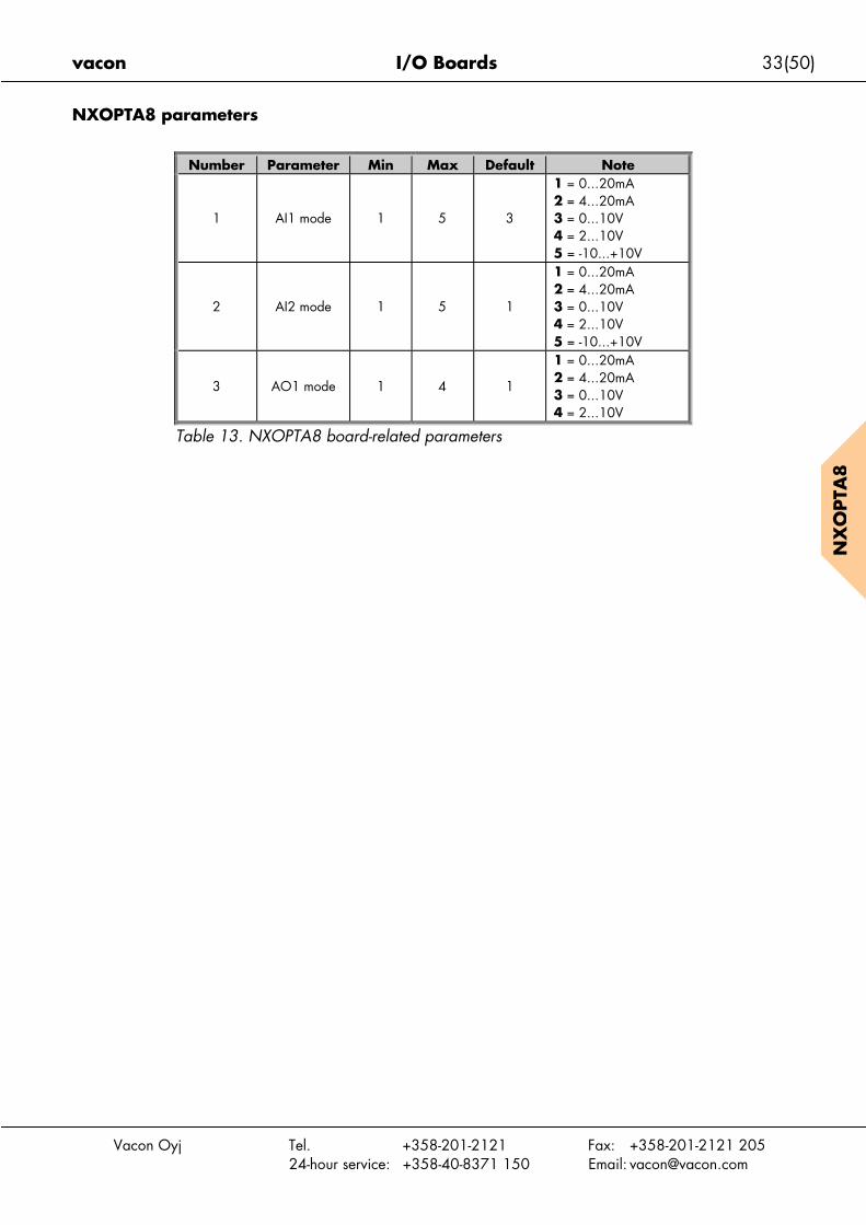
NXOPTA8 parameters
Number Parameter Min Max Default Note
1 AI1 mode 1 5 3
1 = 0...20mA2 = 4...20mA3 = 0...10V4 = 2...10V5 = -10...+10V
2 AI2 mode 1 5 1
1 = 0...20mA2 = 4...20mA3 = 0...10V4 = 2...10V5 = -10...+10V
3 AO1 mode 1 4 1
1 = 0...20mA2 = 4...20mA3 = 0...10V4 = 2...10V
Table 13. NXOPTA8 board-related parameters
34(50) I/O Boards vacon
Vacon Oyj Tel. +358-201-2121 Fax: +358-201-2121 20524-hour service: +358-40-8371 150 Email: [email protected]
NX
OPTA
9
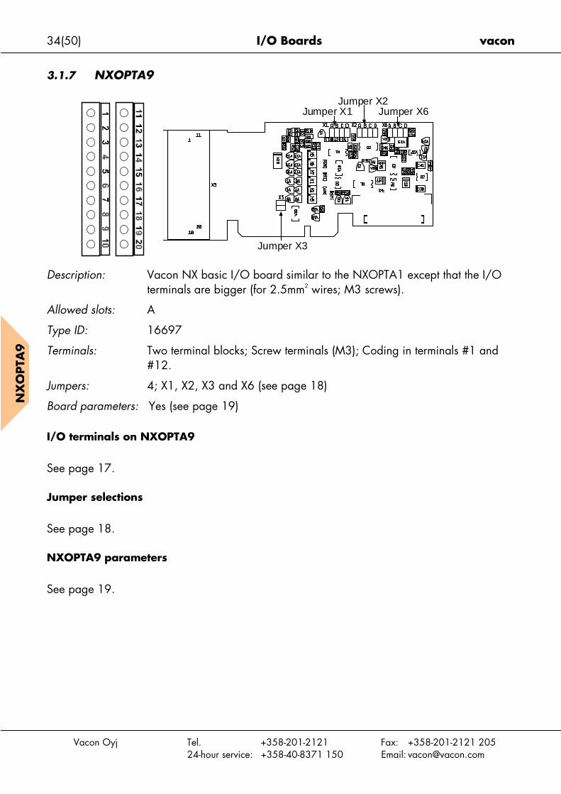
3.1.7 NXOPTA9
Description: Vacon NX basic I/O board similar to the NXOPTA1 except that the I/Oterminals are bigger (for 2.5mm2 wires; M3 screws).
Allowed slots: A
Type ID: 16697
Terminals: Two terminal blocks; Screw terminals (M3); Coding in terminals #1 and#12.
Jumpers: 4; X1, X2, X3 and X6 (see page 18)
Board parameters: Yes (see page 19)
I/O terminals on NXOPTA9
See page 17.
Jumper selections
See page 18.
NXOPTA9 parameters
See page 19.
Jumper X1Jumper X2
Jumper X6
Jumper X3

vacon I/O Boards 35(50)
Vacon Oyj Tel. +358-201-2121 Fax: +358-201-2121 20524-hour service: +358-40-8371 150 Email: [email protected]
3.2 I/O Expander Boards NXOPTB_
• Option boards used for I/O expansion• This board type can be plugged into slots B, C, D or E.
The number of control inputs and outputs on your Vacon frequency converter can be increasedwith the I/O Expander boards. This kind of boards can be placed in any board slot inside thefrequency converter control unit except for slot A.
There are no board-related parameters for NXOPTB_ I/O expander boards.
The boards you wish to have installed in your frequency converter have to be defined in thetype designation code of the frequency converter when ordering it from the factory.
Click on the board name to go to its detailed description.
FCtype
I/Oboard
Allowedslots DI AI TI AO DO RO Pt-100
42-240VACinput
Other
NXSNXP
NXOPTB1 B,C,D,E (6) (6)
NXSNXP
NXOPTB2 B,C,D,E 1 2
NXSNXP NXOPTB4 B,C,D,E
1(isolated);
(mA)
2(isolated mA)
+24V/EXT+24V
NXSNXP
NXOPTB5 B,C,D,E 3
NXSNXP
NXOPTB9 B,C,D,E 1 5
Table 14. Vacon NX I/O Expander boards and their equipment
DI = Digital input Pt-100 = Sensor input for Pt-100AI = Analogue input AO = Analogue outputTI = Thermistor input RO = Relay output

36(50) I/O Boards vacon
Vacon Oyj Tel. +358-201-2121 Fax: +358-201-2121 20524-hour service: +358-40-8371 150 Email: [email protected]
NX
OPTB
1
3.2.1 NXOPTB1
Description: Vacon NX I/O expander board with six bidirectional terminals.
Allowed slots: B, C, D, E
Type ID: 16945
Terminals: One terminal block; Screw terminals (M2.6); No coding
Jumpers: 2; X2 and X4 (see page 37)
Board parameters: None
I/O terminals on NXOPTB1
Terminal Parameter referenceKeypad/NCDrive
Technical information
1 DIO1DigIN: X.1
DigOUT: X.1Digital input: 24V; Ri>5kΩDigital output: Open collector, 50mA/48V
2 DIO2DigIN: X.2
DigOUT: X.2See above.
3 DIO3DigIN: X.3
DigOUT: X.3See above.
4 CMACommon for DIO1…DIO3.Note: CMA is internally connected to GND withjumper by default.
5 DIO4 DigIN: X.4DigOUT: X.4
Digital input: 24V; Ri>5kΩDigital output: Open collector, 50mA/48V
6 DIO5 DigIN: X.5DigOUT: X.5
See above.
7 DIO6 DigIN: X.6DigOUT: X.6
See above.
8 CMB Common for DIO4…DIO69 GND I/O ground; Ground for reference and controls.10 +24V Control voltage output; Voltage for switches etc.;
max. current 150mA; Short-circuit protected.
Table 15. NXOPTB1 I/O terminals
Jumpers X2Jumper X4

vacon I/O Boards 37(50)
Vacon Oyj
Jumper selections
On the NXOPTB1 board, there are two jumper blocks. The jumper block X2 is used to definethe bidirectional terminal as either input or output. The other jumper block, X4, is used toconnect the common terminals to GND. The factory default and other available jumperselections are presented below.
F
Jumper block X2:DIO mode
Jumper block X4:CMA/CMB connection
to GND
Tel. +358-201-2121 Fax: +358-201-2121 20524-hour service: +358-40-8371 150 Email: [email protected]
NX
OPTB
1igure 15. Jumper positions for NXOPTB1
DIO1
DIO2
DIO3
DIO4
DIO5
DIO6
DIO1 to DIO6mode OUT
DIO1
DIO2
DIO3
DIO4
DIO5
DIO6
DIO1 to DIO6mode IN
= Factory default
CMA and CMBconnected to GND
CMACMB
CMACMB
CMA and CMBfloating

38(50) I/O Boards vacon
Vacon Oyj Tel. +358-201-2121 Fax: +358-201-2121 20524-hour service: +358-40-8371 150 Email: [email protected]
NX
OPTB
2
3.2.2 NXOPTB2
Description: Vacon NX I/O expander board with a thermistor input and two relayoutputs.
Allowed slots: B, C, D, E
Type ID: 16946
Terminals: Three terminal blocks; Screw terminals (M3); No coding
Jumpers: None
Board parameters: None
I/O terminals on NXOPTB2
Terminal Parameter referenceKeypad/NCDrive
Technical information
212223
RO1/normal closedRO1/commonRO1/normal open
DigOUT:X.1Switching capacity 24VDC/8A
250VAC/8A125VDC/0.4A
2526
RO2/commonRO2/normal open DigOUT:X.2
Switching capacity 24VDC/8A250VAC/8A125VDC/0.4A
2829
TI1+TI1– DigIN:X.1
Thermistor input (galvanically isolated)Rtrip = 4.7kΩ
Table 16. NXOPTB2 I/O terminals
Note: This expander board can be placed into four different slots on the control board.Therefore, the 'X' given in the Parameter reference shall be replaced by the slot letter (B, C, D,or E) depending on the slot which the expander board is plugged into. See Chapter 1.6.
vacon I/O Boards 39(50)
Vacon Oyj Tel. +358-201-2121 Fax: +358-201-2121 20524-hour service: +358-40-8371 150 Email: [email protected]
NX
OPTB
4
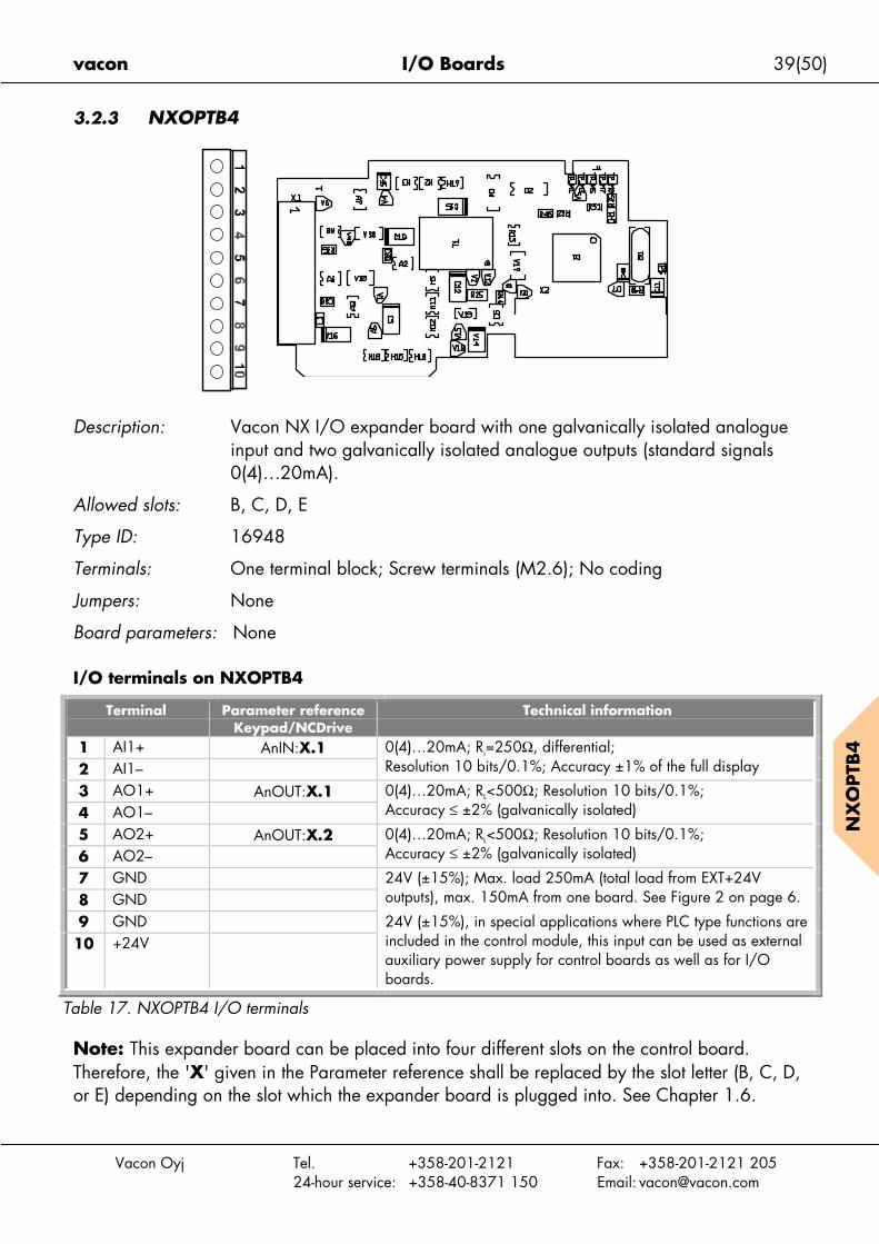
3.2.3 NXOPTB4
Description: Vacon NX I/O expander board with one galvanically isolated analogueinput and two galvanically isolated analogue outputs (standard signals0(4)…20mA).
Allowed slots: B, C, D, E
Type ID: 16948
Terminals: One terminal block; Screw terminals (M2.6); No coding
Jumpers: None
Board parameters: None
I/O terminals on NXOPTB4
Terminal Parameter referenceKeypad/NCDrive
Technical information
1 AI1+ AnIN:X.12 AI1–
0(4)…20mA; Ri=250Ω, differential;Resolution 10 bits/0.1%; Accuracy ±1% of the full display
3 AO1+ AnOUT:X.14 AO1–
0(4)…20mA; RL<500Ω; Resolution 10 bits/0.1%;Accuracy ≤ ±2% (galvanically isolated)
5 AO2+ AnOUT:X.26 AO2–
0(4)…20mA; RL<500Ω; Resolution 10 bits/0.1%;Accuracy ≤ ±2% (galvanically isolated)
7 GND8 GND
24V (±15%); Max. load 250mA (total load from EXT+24Voutputs), max. 150mA from one board. See Figure 2 on page 6.
9 GND10 +24V
24V (±15%), in special applications where PLC type functions areincluded in the control module, this input can be used as externalauxiliary power supply for control boards as well as for I/Oboards.
Table 17. NXOPTB4 I/O terminals
Note: This expander board can be placed into four different slots on the control board.Therefore, the 'X' given in the Parameter reference shall be replaced by the slot letter (B, C, D,or E) depending on the slot which the expander board is plugged into. See Chapter 1.6.

40(50) I/O Boards vacon
Vacon Oyj Tel. +358-201-2121 Fax: +358-201-2121 20524-hour service: +358-40-8371 150 Email: [email protected]
NX
OPTB
5
3.2.4 NXOPTB5
Description: I/O expander board with three relay outputs.
Allowed slots: B, C, D, E
Type ID: 16949
Terminals: Three terminal blocks; Screw terminals (M3); No coding
Jumpers: None
Board parameters: None
I/O terminals on NXOPTB5
Terminal Parameter referenceKeypad/NCDrive
Technical information
2223
RO1/commonRO1/normal open DigOUT:X.1
Switching capacity 24VDC/8A250VAC/8A125VDC/0.4A
2526
RO2/commonRO2/normal open DigOUT:X.2
Switching capacity 24VDC/8A250VAC/8A125VDC/0.4A
2829
RO3/commonRO3/normal open DigOUT:X.3
Switching capacity 24VDC/8A250VAC/8A125VDC/0.4A
Table 18. NXOPTB5 I/O terminals
Note: This expander board can be placed into four different slots on the control board.Therefore, the 'X' given in the Parameter reference shall be replaced by the slot letter (B, C, D,or E) depending on the slot which the expander board is plugged into. See chapter 1.6.
vacon I/O Boards 41(50)
Vacon Oyj Tel. +358-201-2121 Fax: +358-201-2121 20524-hour service: +358-40-8371 150 Email: [email protected]
NX
OPTB
9
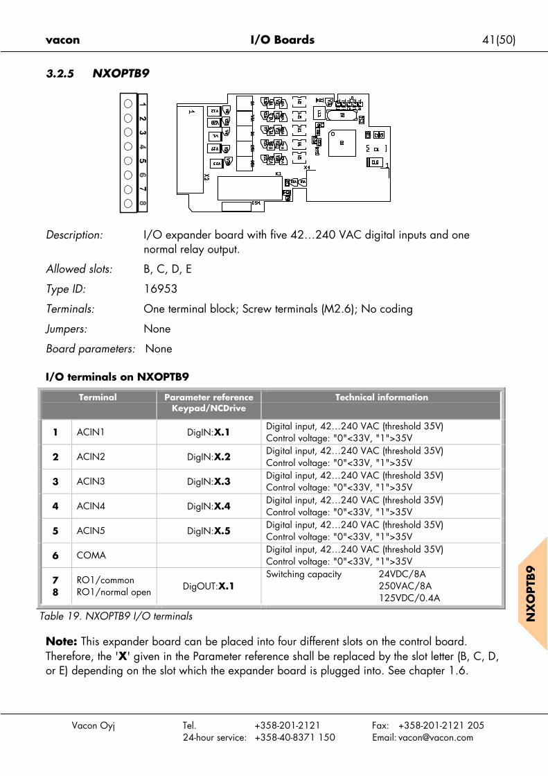
3.2.5 NXOPTB9
Description: I/O expander board with five 42…240 VAC digital inputs and onenormal relay output.
Allowed slots: B, C, D, E
Type ID: 16953
Terminals: One terminal block; Screw terminals (M2.6); No coding
Jumpers: None
Board parameters: None
I/O terminals on NXOPTB9
Terminal Parameter referenceKeypad/NCDrive
Technical information
1 ACIN1 DigIN:X.1Digital input, 42…240 VAC (threshold 35V)Control voltage: "0"<33V, "1">35V
2 ACIN2 DigIN:X.2Digital input, 42…240 VAC (threshold 35V)Control voltage: "0"<33V, "1">35V
3 ACIN3 DigIN:X.3Digital input, 42…240 VAC (threshold 35V)Control voltage: "0"<33V, "1">35V
4 ACIN4 DigIN:X.4Digital input, 42…240 VAC (threshold 35V)Control voltage: "0"<33V, "1">35V
5 ACIN5 DigIN:X.5Digital input, 42…240 VAC (threshold 35V)Control voltage: "0"<33V, "1">35V
6 COMADigital input, 42…240 VAC (threshold 35V)Control voltage: "0"<33V, "1">35V
78
RO1/commonRO1/normal open DigOUT:X.1
Switching capacity 24VDC/8A250VAC/8A125VDC/0.4A
Table 19. NXOPTB9 I/O terminals
Note: This expander board can be placed into four different slots on the control board.Therefore, the 'X' given in the Parameter reference shall be replaced by the slot letter (B, C, D,or E) depending on the slot which the expander board is plugged into. See chapter 1.6.
42(50) I/O Boards vacon
Vacon Oyj Tel. +358-201-2121 Fax: +358-201-2121 20524-hour service: +358-40-8371 150 Email: [email protected]
3.3 Adapter Boards NXOPTD_
The adapter boards do not provide any additional I/O but are used to connect the frequencyconverter to a Vacon communication bus (System Bus, SPI, CAN). Note that if you use any ofthe major fieldbuses (Profibus, Modbus etc.) for communication you will need a correspondingfieldbus board. For more information, see the specific fieldbus board manual.
Note: Do not plug two adapter boards into the same control board in order to avoidincompatibility problems.
FC type I/Oboard
Allowedslots
Description
NXP NXOPTD1 D,E System Bus adapter boardNXP NXOPTD2 D,E
System Bus adapter board withinterface to NCSysDriveBus
Table 20. Vacon NX adapter boards

vacon I/O Boards 43(50)
Vacon Oyj Tel. +358-201-2121 Fax: +358-201-2121 20524-hour service: +358-40-8371 150 Email: [email protected]
NX
OPTD
1N
XO
PTD
1
3.3.1 NXOPTD1
Description: System Bus adapter board for Vacon NXP
Allowed slots: D, E
Type ID: 17457
Terminals: Double optical input and output terminals
Jumpers: None
Board parameters: None
I/O terminals on NXOPTD1
Terminal Technical information
1 H1 System Bus optical input 1 (RX1)2 H2 System Bus optical input 2 (RX2)3 H3 System Bus optical output 1 (TX1)4 H4 System Bus optical output 2 (TX2)
Table 21. NXOPTD1 I/O terminals
Note: The terminals of the board are protected with a rubber pin. Be sure to leave the pin inthe unused terminals in order to avoid disturbances.
H1
H2
H3
H4

44(50) I/O Boards vacon
Vacon Oyj
NX
OPTD
1
Connections between frequency converters with NXOPTD1
Basic connection:Connect the output 1 of Device 1 to the input 2 of Device 2 and the input of Device 1 to theoutput 2 of Device 2. Note that in the end devices one terminal pair remains unused.
Max.number of devices
in line
Max.speed achieved
[Mbit/s]3 126 612 324 1.5
Table 22.
Tel. +358-201-2121 Fax: +358-201-2121 20524-hour service: +358-40-8371 150 Email: [email protected]
Figure 16. Basic connection of frequency converters with NXOPTD1
TX
2
RX
1
TX
1
RX
2
TX
2
RX
1
TX
1
RX
2
TX
2
RX
1
TX
1
RX
2
TX
2
RX
1
TX
1
RX
2
. . .
vacon I/O Boards 45(50)
Vacon Oyj Tel. +358-201-2121 Fax: +358-201-2121 20524-hour service: +358-40-8371 150 Email: [email protected]
NX
OPTD
2
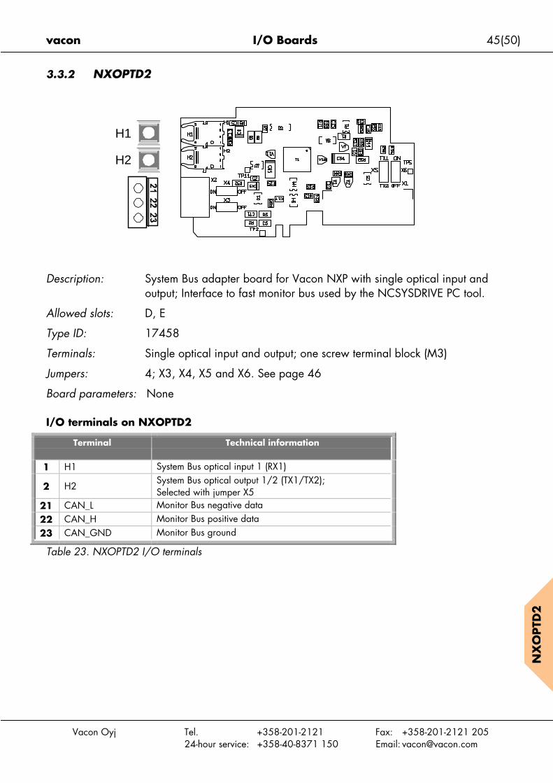
3.3.2 NXOPTD2
Description: System Bus adapter board for Vacon NXP with single optical input andoutput; Interface to fast monitor bus used by the NCSYSDRIVE PC tool.
Allowed slots: D, E
Type ID: 17458
Terminals: Single optical input and output; one screw terminal block (M3)
Jumpers: 4; X3, X4, X5 and X6. See page 46
Board parameters: None
I/O terminals on NXOPTD2
Terminal Technical information
1 H1 System Bus optical input 1 (RX1)
2 H2System Bus optical output 1/2 (TX1/TX2);Selected with jumper X5
21 CAN_L Monitor Bus negative data22 CAN_H Monitor Bus positive data23 CAN_GND Monitor Bus ground
Table 23. NXOPTD2 I/O terminals
H1
H2

46(50) I/O Boards vacon
Vacon Oyj
NX
OPTD
2
Jumper selections
There are four jumper blocks on the NXOPTD2 board. The factory defaults and other availablejumper selections are presented below.
Connections b
Special connec
In this connectMaster can seother. Changin
The NXOPTD2jumper position
Manumber o
in li361224
Table 24.
Jumper block X3:CAN grounding
Jumper block X4:CAN termination
Tel. +358-201-2121 Fax: +358-201-2121 20524-hour service: +358-40-8371 150 Email: [email protected]
Figure 17. Jumper selections for NXOPTD2
etween frequency converters with NXOPTD2
tion: (See next page)
ion example, the leftmost device is the Master and the others are slaves. Thend and receive data from the slaves. The slaves cannot communicate with eachg of masters is not possible, the first device is always the Master.
board in the Master has the default jumper selections, i.e. X6:1-2, X5:1-2. Thes have to be changed for the slaves: X6: 1-2, X5:2-3.
x.f devicesne
Max.speed achieved
[Mbit/s]1263
1.5
Connected to shield Not connected to shield Terminated Not terminated
Jumper block X5:System bus output
Output TX1 Output TX2
Jumper block X6:SystemBus input ON/OFF
ON OFF

vacon I/O Boards 47(50)
Vacon Oyj
F
MASTER SLAVE 1 SLAVE 2 SLAVE ##
Tel. +358-201-2121 Fax: +358-201-2121 20524-hour service: +358-40-8371 150 Email: [email protected]
NX
OPTD
2
igure 18. Connection example of frequency converters with NXOPTD2
R X 1
T X 1
R X 1
T X 2
R X 1
T X 2
. . .
R X 1
T X 2

4. Vacon Option Boards – operational details
Board type Slotsallowed
ID DI DO AI(mA/V)
AI(mA),isol.
AO(mA/V)
AO(mA),isol.
RO(no/nc)
RO(no)
+10Vref
TI+24V/
EXT+24V
42-240VAC
DI(Enc.
10-24V)
DI (Enc.RS-422)
Out+5/
+15V/+24V
Out+15/+24V
Basic boardsNXOPTA_
NXOPTA1 A 16689 6 1 2 1 1 2NXOPTA2 B 16690 2NXOPTA3 B 16691 1 1 1NXOPTA44) C 16692 3 1NXOPTA54) C 16693 3 1NXOPTA8 A 16696 6 1 21) 11) 11) 2NXOPTA93) A 16697 6 1 2 1 1 2I/O expander boardsNXOPTB_
NXOPTB1 BCDE 16945 65) 65)
NXOPTB2 BCDE 16946 1 1 1NXOPTB4 BCDE 16948 12) 22) 1NXOPTB5 BCDE 16949 3NXOPTB9 BCDE 16953 1 1 2 1
Adapter boardsNXOPTD_
NXOPTD1 DE 17457 System Bus adapter board: 2 x fiber optic pairsNXOPTD2 DE 17458 System Bus adapter board: 1 x fiber optic pair & CAN bus adapter (galvanically decoupled)Table 25. Vacon option boards
Explanations:1) Analogue inputs AI1 and AI2, analogue output AO1 and voltage reference +10Vref galvanically decoupled (all these in same potential)2) Analogue input AI1 and analogue outputs AO1 and AO2 galvanically decoupled from each other and other electronics3) Similar to NXOPTA1 only with bigger terminals for 2.5mm2 wires4) Special application required for use in NXS5) Bidirectional terminals
Board typeBasic boardsNXOPTA_
BasicNXFIFF01
StandardNXFIFF02
Local-RemoteNXFIFF03
Multi-stepspeed
NXFIFF04
PIDNXFIFF05
Multi-purposeNXFIFF06
PFCNXFIFF07
NXOPTA1 ! ! ! ! ! !6)
!6)
NXOPTA2 ! ! ! ! ! !6)
!6)
NXOPTA3 ! ! ! ! !6)
!6)
NXOPTA4(NXP only)
" " " " " " "
NXOPTA5(NXP only)
" " " " " " "
NXOPTA8 ! ! ! ! ! !6)
!6)
NXOPTA93) ! ! ! ! ! !6)
!6)
I/O expander boardsNXOPTB_NXOPTB1 !
6)!
6)
NXOPTB2 !6)
!6)
NXOPTB4 !6)
!6)
NXOPTB5 !6)
!6)
NXOPTB9 !6)
!6)
Adapter boardsNXOPTD_NXOPTD1(NXP only)NXOPTD27)
(NXP only)" " " " " " "
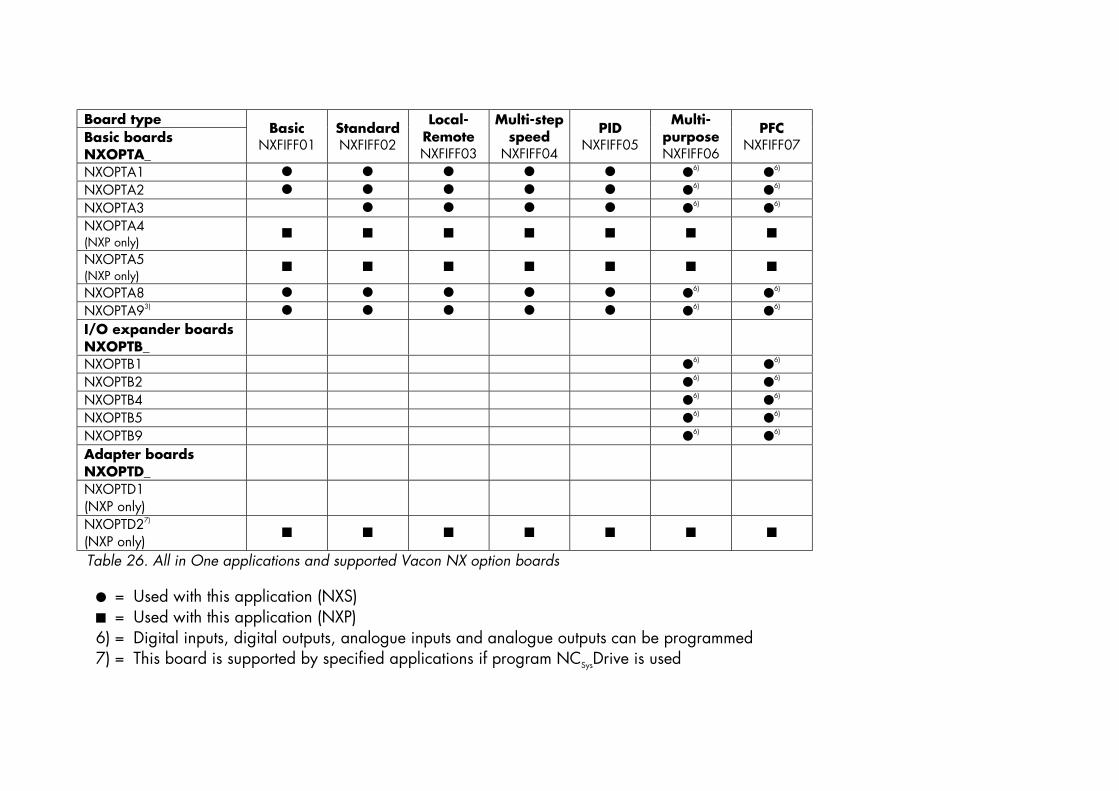
Table 26. All in One applications and supported Vacon NX option boards
! = Used with this application (NXS)" = Used with this application (NXP)6) = Digital inputs, digital outputs, analogue inputs and analogue outputs can be programmed7) = This board is supported by specified applications if program NCSysDrive is used

F O R S M O O T H C O N T R O L
Vacon PlcP.O.Box 25
Runsorintie 765381 VAASA
FINLANDTel: +358-(0)201-2121
Fax: +358-(0)201-212 20524-hour service: +358-(0)40-8371 150
E-mail: [email protected]
ud74
1.do
c15
.01.
02 1
1:14


![Quick User's Guide to NX 3 Plotting_14-0904 - final[1]](https://static.fdocuments.in/doc/165x107/55162597497959ee1d8b5175/quick-users-guide-to-nx-3-plotting14-0904-final1.jpg)